EP4505935A1 - Cleaning assembly with self-cleaning function and electrical apparatus - Google Patents
Cleaning assembly with self-cleaning function and electrical apparatus Download PDFInfo
- Publication number
- EP4505935A1 EP4505935A1 EP23198633.2A EP23198633A EP4505935A1 EP 4505935 A1 EP4505935 A1 EP 4505935A1 EP 23198633 A EP23198633 A EP 23198633A EP 4505935 A1 EP4505935 A1 EP 4505935A1
- Authority
- EP
- European Patent Office
- Prior art keywords
- cleaning
- self
- cylindrical rotating
- channel
- abutting portion
- Prior art date
- Legal status (The legal status is an assumption and is not a legal conclusion. Google has not performed a legal analysis and makes no representation as to the accuracy of the status listed.)
- Withdrawn
Links
Images


Classifications
-
- A—HUMAN NECESSITIES
- A47—FURNITURE; DOMESTIC ARTICLES OR APPLIANCES; COFFEE MILLS; SPICE MILLS; SUCTION CLEANERS IN GENERAL
- A47L—DOMESTIC WASHING OR CLEANING; SUCTION CLEANERS IN GENERAL
- A47L11/00—Machines for cleaning floors, carpets, furniture, walls, or wall coverings
- A47L11/24—Floor-sweeping machines, motor-driven
-
- A—HUMAN NECESSITIES
- A47—FURNITURE; DOMESTIC ARTICLES OR APPLIANCES; COFFEE MILLS; SPICE MILLS; SUCTION CLEANERS IN GENERAL
- A47L—DOMESTIC WASHING OR CLEANING; SUCTION CLEANERS IN GENERAL
- A47L11/00—Machines for cleaning floors, carpets, furniture, walls, or wall coverings
- A47L11/29—Floor-scrubbing machines characterised by means for taking-up dirty liquid
- A47L11/30—Floor-scrubbing machines characterised by means for taking-up dirty liquid by suction
- A47L11/302—Floor-scrubbing machines characterised by means for taking-up dirty liquid by suction having rotary tools
-
- A—HUMAN NECESSITIES
- A47—FURNITURE; DOMESTIC ARTICLES OR APPLIANCES; COFFEE MILLS; SPICE MILLS; SUCTION CLEANERS IN GENERAL
- A47L—DOMESTIC WASHING OR CLEANING; SUCTION CLEANERS IN GENERAL
- A47L11/00—Machines for cleaning floors, carpets, furniture, walls, or wall coverings
- A47L11/40—Parts or details of machines not provided for in groups A47L11/02 - A47L11/38, or not restricted to one of these groups, e.g. handles, arrangements of switches, skirts, buffers, levers
- A47L11/4036—Parts or details of the surface treating tools
- A47L11/4041—Roll shaped surface treating tools
-
- A—HUMAN NECESSITIES
- A47—FURNITURE; DOMESTIC ARTICLES OR APPLIANCES; COFFEE MILLS; SPICE MILLS; SUCTION CLEANERS IN GENERAL
- A47L—DOMESTIC WASHING OR CLEANING; SUCTION CLEANERS IN GENERAL
- A47L11/00—Machines for cleaning floors, carpets, furniture, walls, or wall coverings
- A47L11/40—Parts or details of machines not provided for in groups A47L11/02 - A47L11/38, or not restricted to one of these groups, e.g. handles, arrangements of switches, skirts, buffers, levers
- A47L11/4036—Parts or details of the surface treating tools
- A47L11/4044—Vacuuming or pick-up tools; Squeegees
-
- A—HUMAN NECESSITIES
- A47—FURNITURE; DOMESTIC ARTICLES OR APPLIANCES; COFFEE MILLS; SPICE MILLS; SUCTION CLEANERS IN GENERAL
- A47L—DOMESTIC WASHING OR CLEANING; SUCTION CLEANERS IN GENERAL
- A47L2201/00—Robotic cleaning machines, i.e. with automatic control of the travelling movement or the cleaning operation
Definitions
- the present disclosure relates to cleaning electrical apparatuses, in particular to a cleaning assembly with a self-cleaning function and an electrical apparatus.
- Support surface cleaning apparatuses such as a mopping and washing robot, a robot vacuum and mop combo, a floor cleaning machine, or a hand-held electric mop for cleaning a floor, a table, or other support surfaces have a real-time self-cleaning function.
- an existing cleaning apparatus whether rotating a roller at a high speed to throw waste water out by centrifugal force, or rotating the roller at a low speed to squeeze waste water out by an abutting portion, the general process is that clear water is fed to the roller while the roller cleans a support surface, and then the abutting portion abuts against the roller to separate waste water out.
- the separation process of waste water in some conventional designs is short and rushed.
- the duration of the separation process is related to the speed of the roller, which is less than 0.1 seconds when the roller rotates, for example, at a rate of 400 rpm.
- real-time self-cleaning of the roller may be achieved by means of the process described above, since the separation duration is very short, which prevents a surface of the roller from being sufficiently wetted with clear water, a self-cleaning effect is unsatisfactory.
- the abutting portion of the existing cleaning apparatus also gradually sucks dirt during the process of separating waste water, and lacks effective self-cleaning capacity of the abutting portion.
- the objective of the present disclosure is to provide a cleaning assembly with a self-cleaning function and an electrical apparatus to solve the above problems in the prior art.
- a roller surface of an existing cleaning apparatus is soaked by clear water for a very short time, so it is difficult to be fully wetted; and the existing cleaning apparatus is insufficient in self-cleaning capacity and lacks an effective self-cleaning function.
- a cleaning assembly with a self-cleaning function includes: a cylindrical rotating portion, a curved baffle, and an abutting portion.
- the cylindrical rotating portion may be used for cleaning a support surface, and has a column surface.
- the curved baffle faces the column surface of the cylindrical rotating portion, and may be positioned above the cylindrical rotating portion and spaced from the column surface by a distance.
- the abutting portion may have a first end and a second end, the first end of the abutting portion may be coupled to the curved baffle, and the second end of the abutting portion abuts against the column surface of the cylindrical rotating portion.
- a portion of the column surface of the cylindrical rotating portion, the curved baffle, and the abutting portion together form a channel.
- the channel may be configured such that the interior of the channel is cleaned with a flowing liquid in an operating state.
- a liquid gathering in the channel may flow at a high speed with the cylindrical rotating portion.
- the liquid flowing in the channel of the cleaning assembly with the self-cleaning function is advantageously utilized to autonomously rinse the roller in the channel, the curved baffle and the abutting portion, thereby reducing the need for manual maintenance and improving the user experience.
- the channel has an opening, and the abutting portion and the opening are positioned on two sides of a highest point of the cylindrical rotating portion respectively and are below the highest point.
- the liquid which flows through the highest point of the cylindrical rotating portion may accelerate to flow towards the abutting portion by utilizing the force of gravity, so that the intensify of rinsing the abutting portion is enhanced, thereby achieving a better self-cleaning effect.
- the cylindrical rotating portion rotates in a direction from the opening of the channel to the abutting portion.
- the liquid may be fed from the opening of the channel to the abutting portion through the cylindrical rotating portion.
- the liquid in response to the rotation of the cylindrical rotating portion, the liquid flows in the rotation direction and rinses a portion of the column surface of the cylindrical rotating portion, an inner surface of the curved baffle, and an inner surface of the abutting portion inside the channel.
- the liquid gathering in the channel may flow to the abutting portion with the rotation of the cylindrical rotating portion and thereby rinse the interior of the channel and the interior of the abutting portion, thereby achieving a better self-cleaning effect.
- a shape of the curved baffle is adapted to a shape of the column surface of the cylindrical rotating portion. In this way, turbulence formed by the liquid flowing in the channel between the curved baffle and the cylindrical rotating portion may be reduced, and accordingly the kinetic energy carried by the liquid is maintained as much as possible, thereby achieving a better self-cleaning effect.
- the first end of the abutting portion is detachably coupled to the curved baffle.
- the abutting portion may be removed from the curved baffle for maintenance or be replaced with a new abutting portion, as needed.
- the abutting portion and the curved baffle are formed as a whole.
- strong bonding between the abutting portion and the curved baffle is obtained, and this one-piece structure is capable of withstanding greater rinsing force than the removable abutting portion, thereby improving a self-cleaning effect.
- the curved baffle further includes a diversion port.
- the diversion port is coupled to a surface of the curved baffle facing the cylindrical rotating portion, and configured to provide the liquid to the channel.
- a clean liquid for example, water
- a clean liquid may be fed directly from the diversion port into the channel for rinsing the interior of the channel and the interior of the abutting portion.
- the abutting portion further includes a discharge port, and the discharge port is provided between the first end and the second end of a scraping strip to allow the liquid to flow out of the channel in the operating state.
- a dirty liquid e.g., waste water
- the discharge port is provided between the first end and the second end of a scraping strip to allow the liquid to flow out of the channel in the operating state.
- the cleaning assembly with the self-cleaning function further includes: a first vacuum source coupled to the discharge port, where the first vacuum source is in fluid communication with the channel through the discharge port.
- the first vacuum source in fluid communication with the discharge port is used to apply a negative pressure at the discharge port, thereby accelerating the discharge of the liquid flowing to the discharge port of the abutting portion to achieve a better self-cleaning effect.
- the cleaning assembly with the self-cleaning function further includes: a second vacuum source having a vacuum opening, the vacuum opening being positioned on the curved baffle and adjacent to the abutting portion, where the second vacuum source is in fluid communication with the channel through the vacuum opening.
- the distance has a length of 2 mm-8 mm. This distance enables a faster flow rate of the liquid in the channel than a larger separation distance, resulting in a stronger rinsing force on the inner surface of the channel and the abutting portion, thus achieving a better self-cleaning effect.
- the second end of the abutting portion is provided with a scraping strip for squeezing and scraping the column surface of the cylindrical rotating portion. In this way, waste water and dirt adsorbed on and by the column surface of the cylindrical rotating portion may be effectively cleaned up.
- an electrical apparatus in another aspect of the present disclosure, includes: a main body; the cleaning assembly with the self-cleaning function according to one or more embodiments described above, coupled to the main body; and a waste water tank, coupled to the main body and configured to receive waste water from the cleaning assembly with the self-cleaning function.
- the electrical apparatus includes any one of the following: a robot vacuum cleaner, a mopping robot, a floor cleaning machine, a robot vacuum and mop combo, or a hand-held electric mop.
- references to "an embodiment” or “an implementation” in the framework of this specification are intended to indicate that a particular configuration, structure, or feature described with respect to that embodiment is included in at least one embodiment. Accordingly, phrases of "in embodiments,” “in an embodiment,” and the like that may appear in various aspects of this specification do not necessarily refer to the same embodiment exactly. Furthermore, particular configurations, structures, or features may be combined in one or more embodiments in any suitable manner.
- a cleaning electrical apparatus utilizes a drum to scrub a floor to remove dirt from the floor. After the dirt on the floor is scrubbed by the drum and adheres to a surface of the drum, the dirt adhering to the surface of the drum is typically removed by squeezing and scraping an abutting portion of the drum as the drum is further rotated.
- the known cleaning electrical apparatus still requires frequent manual maintenance to remove the dirt adhering to the surface of the abutting portion even after it has been used.
- the present disclosure provides a cleaning assembly with a self-cleaning function.
- the cleaning assembly cleans a cylindrical rotating portion and a curved baffle and an abutting portion matching therewith in real time during the normal operation of a cleaning electrical apparatus, thereby improving the self-cleaning capacity of the cleaning electrical apparatus and reducing the frequency and time of manual maintenance.
- the embodiments of the present disclosure by using the surface of the cylindrical rotating portion, the curved baffle, and the abutting portion to form a channel that may temporarily gather and direct a flowing liquid (such as clear water or a cleaning liquid) to prolong the contact time of the liquid with the surface of the cylindrical rotating portion, the wettability of the cylindrical rotating portion is improved.
- the liquid flowing in the channel is able to continuously rinse the surfaces of the cylindrical rotating portion, the curved baffle, and the abutting portion in the channel in an operating state, thereby effectively achieving a self-cleaning function of the cleaning electrical apparatus.
- the embodiments of the present disclosure do not require any change in the original structure and positional layout of the cylindrical rotating portion and a cylindrical rotating portion holder.
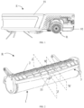
- FIG. 1 illustrates a schematic diagram of an electrical apparatus E according to an embodiment of the present disclosure.
- the electrical apparatus E includes a main body 91, a cleaning assembly R with a self-cleaning function, and a waste water tank 92.
- the cleaning assembly R with the self-cleaning function and the waste water tank 92 are coupled to the main body 91, and the waste water tank 92 is configured to receive waste water from the cleaning assembly with the self-cleaning function in a cleaning operating state.
- the cleaning assembly R with the self-cleaning function may perform a self-cleaning function in real time while cleaning a support surface as the main body 91 moves on the support surface.
- waste water in the waste water tank 92 may be discharged by the electrical apparatus E autonomously, or by means of manual operation.
- FIG. 1 illustrates an example of the electrical apparatus E as a robot vacuum cleaner, however, the scope of the present disclosure is not limited thereto.
- the electrical apparatus E according to the present disclosure includes any of the following: a robot vacuum cleaner, a mopping robot, a floor cleaning machine, a robot vacuum and mop combo, a hand-held electric mop, or any apparatus with a cylindrical rotating portion for cleaning a support surface.
- Advantages of the electrical apparatus E according to the present disclosure will be specifically described in conjunction with the cleaning assembly R with the self-cleaning function with specific reference to FIG. 2 to FIG. 5B .
- FIG. 2 to FIG. 5B illustrate a cleaning assembly R with a self-cleaning function according to various embodiments of the present disclosure.
- the cleaning assembly R with the self-cleaning function illustrated in FIG. 2 includes a cylindrical rotating portion 1, a curved baffle 2, and an abutting portion 3.
- the cylindrical rotating portion 1 may rotate and scrub a support surface in contact therewith.
- the curved baffle 2 may be configured to prevent dirt (or waste water) adhering to a surface of the cylindrical rotating portion 1 during scrubbing of the support surface from being thrown out when the cylindrical rotating portion 1 rotates at a high speed (e.g., 400 rpm).
- the abutting portion 3 may abut against the surface of the cylindrical rotating portion 1, and may scrape the surface of the cylindrical rotating portion 1 as the cylindrical rotating portion 1 rotates, so as to remove the dirt adhering to the surface of the cylindrical rotating portion 1.
- the abutting portion 3 may have a discharge port 33.
- the discharge port 33 may be provided at a middle position of the abutting portion 3 in a direction extending along the rotation axis of the cylindrical rotating portion 1. After being removed from the surface of the cylindrical rotating portion 1, the dirt may be discharged out of the cleaning assembly R with the self-cleaning function via the discharge port 33.
- a waste water tank that cooperates with the discharge port 33 may be provided to collect the dirt from the discharge port 33.
- FIG. 3 exemplarily illustrates a cross-section of the cleaning assembly R with the self-cleaning function intercepted along a plane W-W in FIG. 2 in an operating state.
- FIG. 3 illustrates dirt 9 (or waste water) located on the support surface 8.
- the cylindrical rotating portion 1 of the cleaning assembly R with the self-cleaning function may be used for removing the dirt 9 from the support surface 8 by means of rotation.
- the cylindrical rotating portion 1 may have a column surface 11, and the column surface 11 may have a rough but soft surface.
- the column surface 11 may be provided with a cleaning cloth to scrub the support surface 8 as the cylindrical rotating portion 1 rotates.
- the dirt 9 may also be clear water, or other cleaning liquids, or the like.
- the curved baffle 2 may face the column surface 11 of the cylindrical rotating portion 1 and may be positioned above the cylindrical rotating portion 1 and spaced from the column surface 11 by a first distance d1.
- the value of the first distance d1 may significantly affect the flow rate of a liquid in a channel 4.
- a small first distance d1 compared to a larger first distance d1 results in a faster flow rate of the liquid in the channel 4, thereby obtaining stronger rinsing force for an inner surface of the channel 4 and the abutting portion 3.
- the first distance d1 may be less than 8 millimeters, for example, 6-7 millimeters.
- the first distance d1 may be less than 2 millimeters.
- the curved baffle 2 may have an interference contact with the column surface 11 having the cleaning cloth in a dry state.
- the first distance d1 between the column surface 11 and the curved baffle 2 is still kept no more than 8 millimeters, for example, 6-7 millimeters.
- the curved baffle 2 is provided with a low side end 25 and a high side end 26.
- the low side end 25 of the curved baffle 2 may extend downward to a height below a rotation axis 121 of the cylindrical rotating portion 1.
- dirt 9 or waste water
- the high side end 26 of the curved baffle 2 is coupled to the first end 31 of the abutting portion 3.
- the second end 32 of the abutting portion 3 which is not coupled to the curved baffle 2 abuts against the column surface 11 of the cylindrical rotating portion 1.
- the dirt 9 sucked by the column surface 11 of the cylindrical rotating portion 1 causes clear water previously wetting the column surface 11 to turn into waste water.
- the second end 32 of the abutting portion 3 interferes with and squeezes the column surface 11 in a position against the column surface 11.
- waste water in the cleaning cloth is discharged by squeezing of the second end 32 of the abutting portion 3 for re-wetting and absorbing clear water.
- the second end 32 of the abutting portion 3 is also configured to scrape the column surface 11 duration rotation of the cylindrical rotating portion 1, so as to remove the dirt 9 sucked by the column surface 11 from the column surface 11.
- the column surface 11, the curved baffle 2, and the abutting portion 3 form the channel 4.
- the channel 4 may have an opening 41, and the channel 4 may be configured to gather and direct a flowing fluid 93 in the operating state.
- the cylindrical rotating portion 1 may rotate from the opening 41 toward the abutting portion 3 along a rotation direction 81.
- the liquid 93 may come from the cleaning liquid 93 provided on the support surface 8.
- the liquid 93 wets the column surface 11 and is adsorbed by the column surface 11 as making contact with the column surface 11 of the cylindrical rotating portion 1, and then enters the channel 4 as the cylindrical rotating portion 1 rotates.
- the liquid 93 may also be a cleaning liquid 93, e.g., clear water, that is fed directly into the channel 4.
- the flowing liquid 93 in the channel 4 is configured to flow with the rotation of the cylindrical rotating portion 1, so as to rinse the column surface 11 of the cylindrical rotating portion as well as surfaces of the curved baffle 2 and the abutting portion 3 in the channel 4.
- the cleaning assembly R with the self-cleaning function according to an embodiment of the present disclosure achieves the self-cleaning function, and the service life is prolonged.
- the low side end 25 of the curved baffle 2 and the column surface 11 of the cylindrical rotating portion 1 form the opening 41 of the channel 4.
- the opening 41 is also positioned at a height below the rotation axis 121.
- a height difference between the opening 41 or the low side end 25 and the rotation axis 121 is d2. In this way, it is possible to receive as early and as much as possible the dirt (or waste water) splashed by the rotation of the cylindrical rotating portion 1 with the opening 41.
- the high side end 26 of the curved baffle 2 may be positioned on the other side opposite to the side of the opening 41 and is below the highest point 111 of the cylindrical rotating portion 1. That is, the abutting portion 3 is coupled to a position that is below the highest point 111 of the cylindrical rotating portion 1 and above the rotation axis 121, and the abutting portion and the opening 41 are located on two sides of the highest point 111 respectively.
- the abutting portion 3 is coupled such that a height difference between the second end 32 thereof and the highest point 111 of the cylindrical rotating portion 1 is a distance d3.
- the cylindrical rotating portion rotates in the direction 81 from the opening 41 to the abutting portion 3, and when the liquid 93 flows in the channel 4 and flows from the opening 41 on one side of the highest point 111 of the cylindrical rotating portion 1 to the abutting portion 3 on the other side, due to the height difference between the abutting portion 3 and the highest point 111 of the cylindrical rotating portion 1, the liquid 93 which flows through the highest point 111 of the cylindrical rotating portion 1 may accelerate to flow towards the abutting portion 3 by utilizing the force of gravity, so that the intensify of rinsing the abutting portion 3 is enhanced, thereby achieving a better self-cleaning effect.
- the high side end 26 is higher than the rotation axis 121, the scope of the present disclosure is not limited thereto.
- the high side end 26 may alternatively be lower than the rotation axis 121.
- the high side end 26 and the first end 31 may be coupled together in a removable manner.
- the abutting portion 3 may be easily removed from the cleaning assembly R with the self-cleaning function and maintained, or replaced with a spare abutting portion 3.
- the second end 32 of the abutting portion 3 may have a scraping strip made of different materials.
- a user of the cleaning assembly R with the self-cleaning function may have the flexibility to select the abutting portion 3 with a metal scraping strip, a hard rubber scraping strip, a plastic scraping strip, or a scraping strip made of any other suitable material to be mounted to the cleaning assembly R with the self-cleaning function.
- the embodiments of the present disclosure have the flexibility to select the material of the abutting portion as needed.
- the curved baffle 2 and the abutting portion 3 may be formed into a whole.
- strong bonding between the abutting portion 3 and the curved baffle 2 is obtained, and this one-piece structure is capable of withstanding greater rinsing force than the removable abutting portion 3, thereby improving a self-cleaning effect.
- the shape of the curved baffle 2 may be configured to adapt to the shape of the column surface 11 of the cylindrical rotating portion 1. For example, by configuring the shape of the surface of the curved baffle 2 in the channel 4, the flowing performance of the liquid 93 in the channel 4 may be improved. By adapting the shape of the curved baffle 2 to the shape of the column surface 11, the velocity difference in the profile of the liquid 93 flowing in the channel 4 may be reduced, and accordingly the pressure difference is reduced, thereby reducing local turbulence of the liquid 93 flowing in the channel 4. In this way, the kinetic energy carried by the liquid is maintained as much as possible, thus achieving a better self-cleaning effect.
- FIG. 4 illustrates a cross-sectional view of a cleaning assembly R with a self-cleaning function according to another embodiment of the present disclosure.
- the same components as those described above with respect to the embodiment illustrated in FIG. 3 will be identified with the same reference numerals and will not be repeated herein.
- the curved baffle 2 illustrated in FIG. 4 may further include a diversion port 23.
- the diversion port 23 is coupled to the surface of the curved baffle 2 in the channel 4 and is configured to provide the liquid 93 to the channel 4.
- the liquid 93 may be clear water, or a cleaning liquid having a cleaning agent.
- the amount of the liquid 93 provided by the diversion port 23 may be adjusted in real time.
- the diversion port 23 may be configured to increase the amount of the liquid 93 provided by the diversion port 23 when it is detected by the cleaning assembly R with the self-cleaning function that dirt fails to be removed from the surfaces of the curved baffle 2 and the abutting portion 3 in the channel 4 with a relatively small amount of liquid 93.
- the diversion port 23 may be configured to increase the amount of the liquid 93 provided by the diversion port 23 when it is detected by the cleaning assembly R with the self-cleaning function that the column surface 11 is dry and needs to be wetted. It is to be understood that the diversion port 23 may also decrease the amount of the liquid 93 provided by the diversion port based on the conditions detected by the cleaning assembly R with the self-cleaning function.
- the diversion port 23 may be configured to selectively provide various liquids 93 based on set conditions.
- the diversion port 23 may be configured to provide clear water, a cleaning liquid, a support surface care liquid, or a mixture of the above to assist the cleaning assembly R with the self-cleaning function in a variety of different cleaning tasks.
- FIG. 4 illustrates the diversion port 23 being positioned over the cylindrical rotating portion 1, the scope of the present disclosure is not limited thereto.
- the diversion port 23 may also be provided at the low side end 25 of the curved baffle 2 in the channel 4, so as to provide the liquid 93 with more time to be in contact with and wet the column surface 11 of the cylindrical rotating portion 1 before reaching the abutting portion 3.
- the diversion port 23 may also be provided on a surface of a side opposite to the side of the curved baffle 2 facing the interior of the channel 4 (i.e., provided on an outer side of the curved baffle 2), so as to provide the liquid 93 directly to the support surface 8.
- FIG. 4 illustrates only a cross-section of an exemplary embodiment of the present disclosure.
- the cleaning assembly R with the self-cleaning function may have a plurality of diversion ports 23, and that the plurality of diversion ports 23 may be arranged on the surface of the curved baffle 2 along the entire extension length of the curved baffle 2 in the direction of the rotation axis 121 of the cylindrical rotating portion 1.
- FIG. 5A and FIG. 5B illustrate cross-sections of the cleaning assembly R with the self-cleaning function intercepted at a plane Z-Z shown in FIG. 2 according to various embodiments.
- the same components as those described above with respect to the embodiment illustrated in FIG. 3 will be identified with the same reference numerals and will not be repeated herein.
- the liquid may be discharged via the discharge port 33.
- the discharge port 33 may be located at a middle position of the abutting portion 3 in the extension direction of the rotation axis 121 of the cylindrical rotating portion 1.
- the liquid 93 arriving at both sides of the abutting portion 3, and a liquid 93 seeping out by squeezing the column surface 11 through the abutting portion may also flow from the portions on both sides of the abutting portion 3 toward the discharge port 33 located at the middle position respectively in the extension direction of the rotation axis 121 of the cylindrical rotating portion 1, and are then discharged via the discharge port 33.
- the first vacuum source 22 may be coupled to the discharge port 33, whereby fluid communication between the first vacuum source 22 and the channel 4 may be obtained.
- the flowing of the fluid 93 towards the abutting portion 3, as well as the flow rate of the fluid 93 from the portions on both sides of the abutting portion 3 towards the discharge port 33 in the extension direction of the rotation axis 121 of the cylindrical rotating portion 1 may be further accelerated.
- the abutting portion 3 does not have a discharge port 33.
- the cleaning assembly R with the self-cleaning function according to FIG. 5B may have a second vacuum source 24, and a vacuum opening 221 that is positioned on the curved baffle 2 in the channel 4 and adjacent to the abutting portion 3.
- the vacuum opening 221 may be configured to achieve fluid communication between the second vacuum source 24 and the channel 4. In this case, the discharge of the fluid 93 in the channel 4 relies primarily on the negative pressure generated by the second vacuum source 24.
- the second vacuum source 24 may also be configured to flexibly control the volume flow rate of the liquid 93 discharged from the channel 4.
Landscapes
- Cleaning In General (AREA)
- Cleaning By Liquid Or Steam (AREA)
Abstract
The present disclosure relates to a cleaning assembly (R) with a self-cleaning function, and an electrical apparatus (E). The cleaning assembly (R) with the self-cleaning function includes: a cylindrical rotating portion (1), a curved baffle (2), and an abutting portion (3). The cylindrical rotating portion (1) is used for cleaning a support surface (8), and has a column surface (11). The curved baffle (2) faces the column surface (11) of the cylindrical rotating portion (1), and is positioned above the cylindrical rotating portion (1) and spaced from the column surface (11) by a distance. The abutting portion (3) has a first end (31) and a second end (32), the first end (31) of the abutting portion (3) is coupled to the curved baffle (2), and the second end (32) of the abutting portion (3) abuts against the column surface (11) of the cylindrical rotating portion (1). A portion of the column surface (11) of the cylindrical rotating portion (1), the curved baffle (2), and the abutting portion (3) together form a channel (4). The channel (4) is configured such that the interior of the channel (4) is cleaned with a flowing liquid in an operating state. According to the embodiments of the present disclosure, the cleaning assembly with the self-cleaning function advantageously utilizes the flowing liquid in the channel to autonomously rinse a roller in the channel, the curved baffle and the abutting portion, thereby reducing the need for manual maintenance and improving user experience.
Description
- The present disclosure relates to cleaning electrical apparatuses, in particular to a cleaning assembly with a self-cleaning function and an electrical apparatus.
- Support surface cleaning apparatuses such as a mopping and washing robot, a robot vacuum and mop combo, a floor cleaning machine, or a hand-held electric mop for cleaning a floor, a table, or other support surfaces have a real-time self-cleaning function. However, an existing cleaning apparatus, whether rotating a roller at a high speed to throw waste water out by centrifugal force, or rotating the roller at a low speed to squeeze waste water out by an abutting portion, the general process is that clear water is fed to the roller while the roller cleans a support surface, and then the abutting portion abuts against the roller to separate waste water out.
- The separation process of waste water in some conventional designs is short and rushed. For example, the duration of the separation process is related to the speed of the roller, which is less than 0.1 seconds when the roller rotates, for example, at a rate of 400 rpm. Although real-time self-cleaning of the roller may be achieved by means of the process described above, since the separation duration is very short, which prevents a surface of the roller from being sufficiently wetted with clear water, a self-cleaning effect is unsatisfactory. In addition, the abutting portion of the existing cleaning apparatus also gradually sucks dirt during the process of separating waste water, and lacks effective self-cleaning capacity of the abutting portion.
- The objective of the present disclosure is to provide a cleaning assembly with a self-cleaning function and an electrical apparatus to solve the above problems in the prior art. For example, a roller surface of an existing cleaning apparatus is soaked by clear water for a very short time, so it is difficult to be fully wetted; and the existing cleaning apparatus is insufficient in self-cleaning capacity and lacks an effective self-cleaning function.
- In one aspect of the present disclosure, a cleaning assembly with a self-cleaning function is provided. The cleaning assembly includes: a cylindrical rotating portion, a curved baffle, and an abutting portion. The cylindrical rotating portion may be used for cleaning a support surface, and has a column surface. The curved baffle faces the column surface of the cylindrical rotating portion, and may be positioned above the cylindrical rotating portion and spaced from the column surface by a distance. The abutting portion may have a first end and a second end, the first end of the abutting portion may be coupled to the curved baffle, and the second end of the abutting portion abuts against the column surface of the cylindrical rotating portion. A portion of the column surface of the cylindrical rotating portion, the curved baffle, and the abutting portion together form a channel. The channel may be configured such that the interior of the channel is cleaned with a flowing liquid in an operating state.
- By means of the embodiments of the present disclosure, through high-speed rotation of the cylindrical rotating portion in a normal operating state of the cleaning assembly with the self-cleaning function, a liquid gathering in the channel may flow at a high speed with the cylindrical rotating portion. Thus, the liquid flowing in the channel of the cleaning assembly with the self-cleaning function is advantageously utilized to autonomously rinse the roller in the channel, the curved baffle and the abutting portion, thereby reducing the need for manual maintenance and improving the user experience.
- According to one or more embodiments, the channel has an opening, and the abutting portion and the opening are positioned on two sides of a highest point of the cylindrical rotating portion respectively and are below the highest point. In this way, when the liquid flows from the opening on one side of the highest point of the cylindrical rotating portion to the abutting portion on the other side, due to the height difference between the abutting portion and the highest point of the cylindrical rotating portion, the liquid which flows through the highest point of the cylindrical rotating portion may accelerate to flow towards the abutting portion by utilizing the force of gravity, so that the intensify of rinsing the abutting portion is enhanced, thereby achieving a better self-cleaning effect.
- According to one or more embodiments, in the operating state, the cylindrical rotating portion rotates in a direction from the opening of the channel to the abutting portion. Thus, the liquid may be fed from the opening of the channel to the abutting portion through the cylindrical rotating portion.
- According to one or more embodiments, in response to the rotation of the cylindrical rotating portion, the liquid flows in the rotation direction and rinses a portion of the column surface of the cylindrical rotating portion, an inner surface of the curved baffle, and an inner surface of the abutting portion inside the channel. In this way, the liquid gathering in the channel may flow to the abutting portion with the rotation of the cylindrical rotating portion and thereby rinse the interior of the channel and the interior of the abutting portion, thereby achieving a better self-cleaning effect.
- According to one or more embodiments, a shape of the curved baffle is adapted to a shape of the column surface of the cylindrical rotating portion. In this way, turbulence formed by the liquid flowing in the channel between the curved baffle and the cylindrical rotating portion may be reduced, and accordingly the kinetic energy carried by the liquid is maintained as much as possible, thereby achieving a better self-cleaning effect.
- According to one or more embodiments, the first end of the abutting portion is detachably coupled to the curved baffle. In this way, the abutting portion may be removed from the curved baffle for maintenance or be replaced with a new abutting portion, as needed.
- According to one or more embodiments, the abutting portion and the curved baffle are formed as a whole. Thus, strong bonding between the abutting portion and the curved baffle is obtained, and this one-piece structure is capable of withstanding greater rinsing force than the removable abutting portion, thereby improving a self-cleaning effect.
- According to one or more embodiments, the curved baffle further includes a diversion port. The diversion port is coupled to a surface of the curved baffle facing the cylindrical rotating portion, and configured to provide the liquid to the channel. In this way, by means of the embodiment of the present disclosure, a clean liquid (for example, water) may be fed directly from the diversion port into the channel for rinsing the interior of the channel and the interior of the abutting portion.
- According to one or more embodiments, the abutting portion further includes a discharge port, and the discharge port is provided between the first end and the second end of a scraping strip to allow the liquid to flow out of the channel in the operating state. In this way, by means of the embodiment of the present disclosure, a dirty liquid (e.g., waste water) may be discharged directly out of the channel via the discharge port to achieve a better self-cleaning effect.
- According to one or more embodiments, the cleaning assembly with the self-cleaning function further includes: a first vacuum source coupled to the discharge port, where the first vacuum source is in fluid communication with the channel through the discharge port. In this way, the first vacuum source in fluid communication with the discharge port is used to apply a negative pressure at the discharge port, thereby accelerating the discharge of the liquid flowing to the discharge port of the abutting portion to achieve a better self-cleaning effect.
- According to one or more embodiments, the cleaning assembly with the self-cleaning function further includes: a second vacuum source having a vacuum opening, the vacuum opening being positioned on the curved baffle and adjacent to the abutting portion, where the second vacuum source is in fluid communication with the channel through the vacuum opening. By positioning the vacuum opening on a position of the curved baffle adjacent to the abutting portion, the speed of the liquid in the channel may be effectively controlled by controlling the strength of the vacuum source, thereby flexibly controlling the volume flow rate of the liquid discharged from the channel.
- According to one or more embodiments, the distance has a length of 2 mm-8 mm. This distance enables a faster flow rate of the liquid in the channel than a larger separation distance, resulting in a stronger rinsing force on the inner surface of the channel and the abutting portion, thus achieving a better self-cleaning effect.
- According to one or more embodiments, the second end of the abutting portion is provided with a scraping strip for squeezing and scraping the column surface of the cylindrical rotating portion. In this way, waste water and dirt adsorbed on and by the column surface of the cylindrical rotating portion may be effectively cleaned up.
- In another aspect of the present disclosure, an electrical apparatus is provided. The electrical apparatus includes: a main body; the cleaning assembly with the self-cleaning function according to one or more embodiments described above, coupled to the main body; and a waste water tank, coupled to the main body and configured to receive waste water from the cleaning assembly with the self-cleaning function.
- According to one or more embodiments, the electrical apparatus includes any one of the following: a robot vacuum cleaner, a mopping robot, a floor cleaning machine, a robot vacuum and mop combo, or a hand-held electric mop.
- The aspects and advantages previously described with respect to the cleaning assembly with the self-cleaning function are accordingly applicable to the electrical apparatus according to the present disclosure, which will thus not be repeated herein.
- Other advantages and designs of the present disclosure are described in detail below with reference to the accompanying drawings, wherein
-
FIG. 1 illustrates an electrical apparatus according to an embodiment of the present disclosure; -
FIG. 2 illustrates a cleaning assembly with a self-cleaning function according to an embodiment of the present disclosure; -
FIG. 3 illustrates a cross-sectional view of a cleaning assembly with a self-cleaning function according to an embodiment of the present disclosure; -
FIG. 4 illustrates a cross-sectional view of a cleaning assembly with a self-cleaning function according to an embodiment of the present disclosure; and -
FIG. 5A and FIG. 5B illustrate cross-sectional views of a cleaning assembly with a self-cleaning function with a vacuum source and a vacuum opening according to an embodiment of the present disclosure. - Corresponding numbers and symbols in different accompanying drawings generally refer to corresponding regions unless otherwise indicated. The accompanying drawings are drawn for the purpose of clearly illustrating relevant aspects of the embodiments and need not be drawn to scale. The edges of features drawn in the accompanying drawings do not necessarily indicate the end of the range of features.
- In the ensuing description, various specific details are shown to provide insight into various examples of embodiments according to the description. Embodiments may be obtained in the absence of one or more specific details, or by utilizing other methods, components, materials, and the like. In other cases, known structures, materials, or operations are not shown or described in detail so as not to obscure aspects of the embodiments.
- References to "an embodiment" or "an implementation" in the framework of this specification are intended to indicate that a particular configuration, structure, or feature described with respect to that embodiment is included in at least one embodiment. Accordingly, phrases of "in embodiments," "in an embodiment," and the like that may appear in various aspects of this specification do not necessarily refer to the same embodiment exactly. Furthermore, particular configurations, structures, or features may be combined in one or more embodiments in any suitable manner.
- Unless otherwise indicated, when reference is made to two elements joined together, this denotes a direct connection without any intermediate element, and when reference is made to two elements coupled together, this denotes that the two elements may be joined or that they may be coupled via one or more other elements.
- The title/reference numerals used herein are provided solely for ease of reading and therefore do not limit the scope of protection or the scope of the embodiments. Identical or similar elements are identified using the same reference numerals.
- In order to perform a floor cleaning operation, a cleaning electrical apparatus utilizes a drum to scrub a floor to remove dirt from the floor. After the dirt on the floor is scrubbed by the drum and adheres to a surface of the drum, the dirt adhering to the surface of the drum is typically removed by squeezing and scraping an abutting portion of the drum as the drum is further rotated. However, as the drum continues to scrub the floor, more and more dirt adheres to the surface of the drum, and as the abutting portion continues to squeeze and scrape the surface of the drum, a portion of the dirt turns to adhere to the surface of the abutting portion and is difficult to remove. Therefore, the known cleaning electrical apparatus still requires frequent manual maintenance to remove the dirt adhering to the surface of the abutting portion even after it has been used.
- As previously mentioned, the self-cleaning capacity of the known cleaning electrical apparatus is unsatisfactory, and therefore the known cleaning electrical apparatus needs to be improved. The present disclosure provides a cleaning assembly with a self-cleaning function. The cleaning assembly cleans a cylindrical rotating portion and a curved baffle and an abutting portion matching therewith in real time during the normal operation of a cleaning electrical apparatus, thereby improving the self-cleaning capacity of the cleaning electrical apparatus and reducing the frequency and time of manual maintenance.
- According to the embodiments of the present disclosure, by using the surface of the cylindrical rotating portion, the curved baffle, and the abutting portion to form a channel that may temporarily gather and direct a flowing liquid (such as clear water or a cleaning liquid) to prolong the contact time of the liquid with the surface of the cylindrical rotating portion, the wettability of the cylindrical rotating portion is improved. In addition, the liquid flowing in the channel is able to continuously rinse the surfaces of the cylindrical rotating portion, the curved baffle, and the abutting portion in the channel in an operating state, thereby effectively achieving a self-cleaning function of the cleaning electrical apparatus. In addition, the embodiments of the present disclosure do not require any change in the original structure and positional layout of the cylindrical rotating portion and a cylindrical rotating portion holder.
-
FIG. 1 illustrates a schematic diagram of an electrical apparatus E according to an embodiment of the present disclosure. The electrical apparatus E includes amain body 91, a cleaning assembly R with a self-cleaning function, and awaste water tank 92. The cleaning assembly R with the self-cleaning function and thewaste water tank 92 are coupled to themain body 91, and thewaste water tank 92 is configured to receive waste water from the cleaning assembly with the self-cleaning function in a cleaning operating state. In the cleaning operating state, the cleaning assembly R with the self-cleaning function may perform a self-cleaning function in real time while cleaning a support surface as themain body 91 moves on the support surface. After the cleaning operation, waste water in thewaste water tank 92 may be discharged by the electrical apparatus E autonomously, or by means of manual operation. -
FIG. 1 illustrates an example of the electrical apparatus E as a robot vacuum cleaner, however, the scope of the present disclosure is not limited thereto. For example, the electrical apparatus E according to the present disclosure includes any of the following: a robot vacuum cleaner, a mopping robot, a floor cleaning machine, a robot vacuum and mop combo, a hand-held electric mop, or any apparatus with a cylindrical rotating portion for cleaning a support surface. Advantages of the electrical apparatus E according to the present disclosure will be specifically described in conjunction with the cleaning assembly R with the self-cleaning function with specific reference toFIG. 2 to FIG. 5B . -
FIG. 2 to FIG. 5B illustrate a cleaning assembly R with a self-cleaning function according to various embodiments of the present disclosure. For example, the cleaning assembly R with the self-cleaning function illustrated inFIG. 2 includes a cylindricalrotating portion 1, acurved baffle 2, and anabutting portion 3. In the cleaning operating state, the cylindricalrotating portion 1 may rotate and scrub a support surface in contact therewith. Thecurved baffle 2 may be configured to prevent dirt (or waste water) adhering to a surface of the cylindricalrotating portion 1 during scrubbing of the support surface from being thrown out when the cylindricalrotating portion 1 rotates at a high speed (e.g., 400 rpm). The abuttingportion 3 may abut against the surface of the cylindricalrotating portion 1, and may scrape the surface of the cylindricalrotating portion 1 as the cylindricalrotating portion 1 rotates, so as to remove the dirt adhering to the surface of the cylindricalrotating portion 1. - In some embodiments, the abutting
portion 3 may have adischarge port 33. Thedischarge port 33 may be provided at a middle position of the abuttingportion 3 in a direction extending along the rotation axis of the cylindricalrotating portion 1. After being removed from the surface of the cylindricalrotating portion 1, the dirt may be discharged out of the cleaning assembly R with the self-cleaning function via thedischarge port 33. In some embodiments, a waste water tank that cooperates with thedischarge port 33 may be provided to collect the dirt from thedischarge port 33. -
FIG. 3 exemplarily illustrates a cross-section of the cleaning assembly R with the self-cleaning function intercepted along a plane W-W inFIG. 2 in an operating state. For example,FIG. 3 illustrates dirt 9 (or waste water) located on thesupport surface 8. The cylindricalrotating portion 1 of the cleaning assembly R with the self-cleaning function may be used for removing thedirt 9 from thesupport surface 8 by means of rotation. In some embodiments, the cylindricalrotating portion 1 may have acolumn surface 11, and thecolumn surface 11 may have a rough but soft surface. For example, thecolumn surface 11 may be provided with a cleaning cloth to scrub thesupport surface 8 as the cylindricalrotating portion 1 rotates. In addition, although the present disclosure illustrates thedirt 9, the scope of the present disclosure is not limited thereto. For example, thedirt 9 may also be clear water, or other cleaning liquids, or the like. - As illustrated in
FIG. 3 , thecurved baffle 2 may face thecolumn surface 11 of the cylindricalrotating portion 1 and may be positioned above the cylindricalrotating portion 1 and spaced from thecolumn surface 11 by a first distance d1. According to an embodiment of the present disclosure, the value of the first distance d1 may significantly affect the flow rate of a liquid in achannel 4. For example, a small first distance d1, compared to a larger first distance d1 results in a faster flow rate of the liquid in thechannel 4, thereby obtaining stronger rinsing force for an inner surface of thechannel 4 and the abuttingportion 3. According to some embodiments of the present disclosure, the first distance d1 may be less than 8 millimeters, for example, 6-7 millimeters. In other embodiments, the first distance d1 may be less than 2 millimeters. For example, when thecolumn surface 11 is provided with a cleaning cloth, thecurved baffle 2 may have an interference contact with thecolumn surface 11 having the cleaning cloth in a dry state. Thus, even when the cleaning cloth of thecolumn surface 11 is wetted and the size is reduced, the first distance d1 between thecolumn surface 11 and thecurved baffle 2 is still kept no more than 8 millimeters, for example, 6-7 millimeters. - In addition, the
curved baffle 2 is provided with alow side end 25 and ahigh side end 26. For example, in some embodiments, thelow side end 25 of thecurved baffle 2 may extend downward to a height below arotation axis 121 of the cylindricalrotating portion 1. Thus, as the cylindricalrotating portion 1 rotates at, for example, a speed of about 400 rpm, dirt 9 (or waste water) that is not successfully sucked to the cylindricalrotating portion 1 but splashed as the cylindrical rotating portion rotates may be effectively blocked by thelow side end 25 of thecurved baffle 2, so as to prevent the spreading of thedirt 9. Thehigh side end 26 of thecurved baffle 2 is coupled to thefirst end 31 of the abuttingportion 3. Thesecond end 32 of the abuttingportion 3 which is not coupled to thecurved baffle 2 abuts against thecolumn surface 11 of the cylindricalrotating portion 1. As the cleaning operation proceeds, thedirt 9 sucked by thecolumn surface 11 of the cylindricalrotating portion 1 causes clear water previously wetting thecolumn surface 11 to turn into waste water. In some embodiments, thesecond end 32 of the abuttingportion 3 interferes with and squeezes thecolumn surface 11 in a position against thecolumn surface 11. For example, when thecolumn surface 11 is provided with the cleaning cloth, waste water in the cleaning cloth is discharged by squeezing of thesecond end 32 of the abuttingportion 3 for re-wetting and absorbing clear water. In addition, thesecond end 32 of the abuttingportion 3 is also configured to scrape thecolumn surface 11 duration rotation of the cylindricalrotating portion 1, so as to remove thedirt 9 sucked by thecolumn surface 11 from thecolumn surface 11. - As illustrated in the embodiment in
FIG. 3 , thecolumn surface 11, thecurved baffle 2, and the abuttingportion 3 form thechannel 4. As shown inFIG. 4 , in some embodiments, thechannel 4 may have anopening 41, and thechannel 4 may be configured to gather and direct a flowingfluid 93 in the operating state. For example, when the cleaning assembly R with the self-cleaning function is moved on thesupport surface 8 along adirection 82, the cylindricalrotating portion 1 may rotate from theopening 41 toward the abuttingportion 3 along arotation direction 81. In some embodiments, the liquid 93 may come from the cleaningliquid 93 provided on thesupport surface 8. The liquid 93 wets thecolumn surface 11 and is adsorbed by thecolumn surface 11 as making contact with thecolumn surface 11 of the cylindricalrotating portion 1, and then enters thechannel 4 as the cylindricalrotating portion 1 rotates. In other embodiments, as will be specifically described below with reference toFIG. 4 , the liquid 93 may also be a cleaningliquid 93, e.g., clear water, that is fed directly into thechannel 4. - The flowing
liquid 93 in thechannel 4 is configured to flow with the rotation of the cylindricalrotating portion 1, so as to rinse thecolumn surface 11 of the cylindrical rotating portion as well as surfaces of thecurved baffle 2 and the abuttingportion 3 in thechannel 4. In this way, the cleaning assembly R with the self-cleaning function according to an embodiment of the present disclosure achieves the self-cleaning function, and the service life is prolonged. - With continued reference to
FIG. 3 , thelow side end 25 of thecurved baffle 2 and thecolumn surface 11 of the cylindricalrotating portion 1 form theopening 41 of thechannel 4. In some embodiments, since thelow side end 25 of thecurved baffle 2 is positioned at the height below therotation axis 121 of the cylindricalrotating portion 1, theopening 41 is also positioned at a height below therotation axis 121. For example, in the embodiment illustrated inFIG. 3 , a height difference between the opening 41 or thelow side end 25 and therotation axis 121 is d2. In this way, it is possible to receive as early and as much as possible the dirt (or waste water) splashed by the rotation of the cylindricalrotating portion 1 with theopening 41. In addition, thehigh side end 26 of thecurved baffle 2 may be positioned on the other side opposite to the side of theopening 41 and is below thehighest point 111 of the cylindricalrotating portion 1. That is, the abuttingportion 3 is coupled to a position that is below thehighest point 111 of the cylindricalrotating portion 1 and above therotation axis 121, and the abutting portion and theopening 41 are located on two sides of thehighest point 111 respectively. For example, in the embodiment illustrated inFIG. 3 , the abuttingportion 3 is coupled such that a height difference between thesecond end 32 thereof and thehighest point 111 of the cylindricalrotating portion 1 is a distance d3. Thus, when the cylindrical rotating portion rotates in thedirection 81 from theopening 41 to the abuttingportion 3, and when the liquid 93 flows in thechannel 4 and flows from theopening 41 on one side of thehighest point 111 of the cylindricalrotating portion 1 to the abuttingportion 3 on the other side, due to the height difference between the abuttingportion 3 and thehighest point 111 of the cylindricalrotating portion 1, the liquid 93 which flows through thehighest point 111 of the cylindricalrotating portion 1 may accelerate to flow towards the abuttingportion 3 by utilizing the force of gravity, so that the intensify of rinsing the abuttingportion 3 is enhanced, thereby achieving a better self-cleaning effect. Although the present disclosure illustrates that thehigh side end 26 is higher than therotation axis 121, the scope of the present disclosure is not limited thereto. For example, thehigh side end 26 may alternatively be lower than therotation axis 121. - In some embodiments, the
high side end 26 and thefirst end 31 may be coupled together in a removable manner. In this way, the abuttingportion 3 may be easily removed from the cleaning assembly R with the self-cleaning function and maintained, or replaced with aspare abutting portion 3. For example, thesecond end 32 of the abuttingportion 3 may have a scraping strip made of different materials. For example, depending on different cleaning needs, a user of the cleaning assembly R with the self-cleaning function may have the flexibility to select the abuttingportion 3 with a metal scraping strip, a hard rubber scraping strip, a plastic scraping strip, or a scraping strip made of any other suitable material to be mounted to the cleaning assembly R with the self-cleaning function. Thus, the embodiments of the present disclosure have the flexibility to select the material of the abutting portion as needed. - In yet other embodiments, the
curved baffle 2 and the abuttingportion 3 may be formed into a whole. Thus, strong bonding between the abuttingportion 3 and thecurved baffle 2 is obtained, and this one-piece structure is capable of withstanding greater rinsing force than the removable abuttingportion 3, thereby improving a self-cleaning effect. - In some embodiments, the shape of the
curved baffle 2 may be configured to adapt to the shape of thecolumn surface 11 of the cylindricalrotating portion 1. For example, by configuring the shape of the surface of thecurved baffle 2 in thechannel 4, the flowing performance of the liquid 93 in thechannel 4 may be improved. By adapting the shape of thecurved baffle 2 to the shape of thecolumn surface 11, the velocity difference in the profile of the liquid 93 flowing in thechannel 4 may be reduced, and accordingly the pressure difference is reduced, thereby reducing local turbulence of the liquid 93 flowing in thechannel 4. In this way, the kinetic energy carried by the liquid is maintained as much as possible, thus achieving a better self-cleaning effect. -
FIG. 4 illustrates a cross-sectional view of a cleaning assembly R with a self-cleaning function according to another embodiment of the present disclosure. The same components as those described above with respect to the embodiment illustrated inFIG. 3 will be identified with the same reference numerals and will not be repeated herein. - The
curved baffle 2 illustrated inFIG. 4 may further include adiversion port 23. Thediversion port 23 is coupled to the surface of thecurved baffle 2 in thechannel 4 and is configured to provide the liquid 93 to thechannel 4. For example, the liquid 93 may be clear water, or a cleaning liquid having a cleaning agent. When the liquid 93 is provided into thechannel 4, the liquid flows from thecolumn surface 11 towards thesecond end 32 of the abuttingportion 3 as the cylindricalrotating portion 1 rotates. According to some embodiments of the present disclosure, the amount of the liquid 93 provided by thediversion port 23 may be adjusted in real time. For example, thediversion port 23 may be configured to increase the amount of the liquid 93 provided by thediversion port 23 when it is detected by the cleaning assembly R with the self-cleaning function that dirt fails to be removed from the surfaces of thecurved baffle 2 and the abuttingportion 3 in thechannel 4 with a relatively small amount ofliquid 93. In other embodiments, thediversion port 23 may be configured to increase the amount of the liquid 93 provided by thediversion port 23 when it is detected by the cleaning assembly R with the self-cleaning function that thecolumn surface 11 is dry and needs to be wetted. It is to be understood that thediversion port 23 may also decrease the amount of the liquid 93 provided by the diversion port based on the conditions detected by the cleaning assembly R with the self-cleaning function. According to yet other embodiments, thediversion port 23 may be configured to selectively providevarious liquids 93 based on set conditions. For example, thediversion port 23 may be configured to provide clear water, a cleaning liquid, a support surface care liquid, or a mixture of the above to assist the cleaning assembly R with the self-cleaning function in a variety of different cleaning tasks. In addition, it is to be understood that whileFIG. 4 illustrates thediversion port 23 being positioned over the cylindricalrotating portion 1, the scope of the present disclosure is not limited thereto. For example, thediversion port 23 may also be provided at thelow side end 25 of thecurved baffle 2 in thechannel 4, so as to provide the liquid 93 with more time to be in contact with and wet thecolumn surface 11 of the cylindricalrotating portion 1 before reaching the abuttingportion 3. In other embodiments not shown, thediversion port 23 may also be provided on a surface of a side opposite to the side of thecurved baffle 2 facing the interior of the channel 4 (i.e., provided on an outer side of the curved baffle 2), so as to provide the liquid 93 directly to thesupport surface 8.FIG. 4 illustrates only a cross-section of an exemplary embodiment of the present disclosure. It is to be understood that the cleaning assembly R with the self-cleaning function according to the present disclosure may have a plurality ofdiversion ports 23, and that the plurality ofdiversion ports 23 may be arranged on the surface of thecurved baffle 2 along the entire extension length of thecurved baffle 2 in the direction of therotation axis 121 of the cylindricalrotating portion 1. -
FIG. 5A and FIG. 5B illustrate cross-sections of the cleaning assembly R with the self-cleaning function intercepted at a plane Z-Z shown inFIG. 2 according to various embodiments. The same components as those described above with respect to the embodiment illustrated inFIG. 3 will be identified with the same reference numerals and will not be repeated herein. - In the embodiment illustrated in
FIG. 5A , after the liquid 93 rinses the interior of thechannel 4 and the abuttingportion 3, the liquid may be discharged via thedischarge port 33. As described in conjunction withFIG. 2 above, thedischarge port 33 may be located at a middle position of the abuttingportion 3 in the extension direction of therotation axis 121 of the cylindricalrotating portion 1. By providing thedischarge port 33 at the middle position of the abuttingportion 3, the liquid 93 arriving at both sides of the abuttingportion 3, and a liquid 93 seeping out by squeezing thecolumn surface 11 through the abutting portion may also flow from the portions on both sides of the abuttingportion 3 toward thedischarge port 33 located at the middle position respectively in the extension direction of therotation axis 121 of the cylindricalrotating portion 1, and are then discharged via thedischarge port 33. In some embodiments, thefirst vacuum source 22 may be coupled to thedischarge port 33, whereby fluid communication between thefirst vacuum source 22 and thechannel 4 may be obtained. Through the negative pressure generated by afirst vacuum source 22, the flowing of the fluid 93 towards the abuttingportion 3, as well as the flow rate of the fluid 93 from the portions on both sides of the abuttingportion 3 towards thedischarge port 33 in the extension direction of therotation axis 121 of the cylindricalrotating portion 1 may be further accelerated. - In the embodiment illustrated in
FIG. 5B , the abuttingportion 3 does not have adischarge port 33. Accordingly, the cleaning assembly R with the self-cleaning function according toFIG. 5B may have asecond vacuum source 24, and avacuum opening 221 that is positioned on thecurved baffle 2 in thechannel 4 and adjacent to the abuttingportion 3. For example, thevacuum opening 221 may be configured to achieve fluid communication between thesecond vacuum source 24 and thechannel 4. In this case, the discharge of the fluid 93 in thechannel 4 relies primarily on the negative pressure generated by thesecond vacuum source 24. Therefore, it is advantageous to be able to effectively control the speed of the liquid 93 flowing in thechannel 4 by controlling the strength of thesecond vacuum source 24, thereby effectively controlling the strength of rinsing the surfaces of thecurved baffle 2 and the abuttingportion 3 as well as thecolumn surface 11 of the cylindricalrotating portion 1 in thechannel 4. In addition, in this way, thesecond vacuum source 24 may also be configured to flexibly control the volume flow rate of the liquid 93 discharged from thechannel 4. - Many of the modified forms and other implementations of the present disclosure given herein will be realized by those skilled in the art to which the present disclosure pertains through the teachings given in the foregoing description and the related accompanying drawings. Thus, it is to be understood that the implementations of the present disclosure are not limited to the specific implementations disclosed, and that the modified forms and other implementations are intended to fall in the scope of the present disclosure. Moreover, while the above description and the associated accompanying drawings describe exemplary implementations in the context of certain exemplary combination forms of components and/or functionality, it should be appreciated that different combination forms of components and/or functionality may be provided by alternative implementations without departing from the scope of the present disclosure. In this regard, for example, other combination forms of components and/or features that differ from those explicitly described above are also anticipated to fall in the scope of the present disclosure. Although specific terms are used herein, they are used in a general and descriptive sense only and are not intended to be limiting.
Claims (15)
- A cleaning assembly (R) with a self-cleaning function, comprising:a cylindrical rotating portion (1) for cleaning a support surface (8), having a column surface (11);a curved baffle (2), facing the column surface (11) of the cylindrical rotating portion (1) and being positioned above the cylindrical rotating portion (1) and spaced from the column surface (11) by a distance (d1); andan abutting portion (3) having a first end (31) and a second end (32), the first end (31) of the abutting portion (3) being coupled to the curved baffle (2), and the second end (32) of the abutting portion (3) abutting against the column surface (11) of the cylindrical rotating portion (1) wherein a portion of the column surface (11) of the cylindrical rotating portion (1), the curved baffle (2), and the abutting portion (3) together form a channel (4), and the channel (4) is configured such that the interior of the channel (4) is cleaned with a flowing liquid (93) in an operating state.
- The cleaning assembly (R) with the self-cleaning function according to claim 1, wherein the channel (4) has an opening (41), and the abutting portion (3) and the opening (41) are positioned on two sides of a highest point (111) of the cylindrical rotating portion (1) respectively and are below the highest point (111).
- The cleaning assembly (R) with the self-cleaning function according to claim 2, wherein in the operating state, the cylindrical rotating portion (1) rotates in a direction (81) from the opening (41) of the channel (4) to the abutting portion (3).
- The cleaning assembly (R) with the self-cleaning function according to claim 3, wherein in response to the rotation of the cylindrical rotating portion (1), the liquid (93) flows in the rotation direction (81) and rinses a portion of the column surface of the cylindrical rotating portion, an inner surface of the curved baffle (2), and an inner surface of the abutting portion (3) inside the channel (4).
- The cleaning assembly (R) with the self-cleaning function according to any one of claims 1 to 4, wherein a shape of the curved baffle (2) is adapted to a shape of the column surface (11) of the cylindrical rotating portion (1).
- The cleaning assembly (R) with the self-cleaning function according to any one of claims 1 to 4, wherein the first end (31) of the abutting portion (3) is detachably coupled to the curved baffle (2).
- The cleaning assembly (R) with the self-cleaning function according to any one of claims 1 to 4, wherein the abutting portion (3) and the curved baffle (2) are formed as a whole.
- The cleaning assembly (R) with the self-cleaning function according to any one of claims 1 to 4, wherein the curved baffle (2) further comprises a diversion port (23), and the diversion port (23) is coupled to a surface of the curved baffle (2) facing the cylindrical rotating portion (1), and configured to provide the liquid (93) to the channel (4).
- The cleaning assembly (R) with the self-cleaning function according to any one of claims 1 to 4, wherein the abutting portion (3) further comprises a discharge port (33), and the discharge port (33) is provided between the first end (31) and the second end (32) to allow the liquid (93) to flow out of the channel (4) in the operating state.
- The cleaning assembly (R) with the self-cleaning function according to claim 9, further comprising:
a first vacuum source (22) coupled to the discharge port (33), wherein the first vacuum source (22) is in fluid communication with the channel (4) through the discharge port (33). - The cleaning assembly (R) with the self-cleaning function according to any one of claims 1 to 4, further comprising:
a second vacuum source (24) having a vacuum opening (221), the vacuum opening (221) being positioned on the curved baffle (2) and adjacent to the abutting portion (3), wherein the second vacuum source (24) is in fluid communication with the channel (4) through the vacuum opening (221). - The cleaning assembly (R) with the self-cleaning function according to any one of claims 1 to 4, wherein the distance (d1) has a length of 2 mm-8 mm.
- The cleaning assembly (R) with the self-cleaning function according to any one of claims 1 to 4, wherein the second end (32) of the abutting portion (3) is provided with a scraping strip for squeezing and scraping the column surface (11) of the cylindrical rotating portion (1).
- An electrical apparatus (E), comprising:a main body (91);the cleaning assembly (R) with the self-cleaning function according to any one of claims 1 to 13, coupled to the main body (91); anda waste water tank (92), coupled to the main body (91) and configured to receive waste water from the cleaning assembly with the self-cleaning function.
- The electrical apparatus (E) according to claim 14, wherein the electrical apparatus (E) comprises any one of the following: a robot vacuum cleaner, a mopping robot, a floor cleaning machine, a robot vacuum and mop combo, or a hand-held electric mop.
Priority Applications (3)
| Application Number | Priority Date | Filing Date | Title |
|---|---|---|---|
| AU2024323689A AU2024323689A1 (en) | 2023-08-11 | 2024-08-05 | Cleaning assembly with self-cleaning function and electrical apparatus |
| PCT/EP2024/072148 WO2025036758A1 (en) | 2023-08-11 | 2024-08-05 | Cleaning assembly with self-cleaning function and electrical apparatus |
| KR1020267007416A KR20260048627A (en) | 2023-08-11 | 2024-08-05 | Cleaning assembly and electrical device with self-cleaning function |
Applications Claiming Priority (1)
| Application Number | Priority Date | Filing Date | Title |
|---|---|---|---|
| CN202311011108.6A CN119453839A (en) | 2023-08-11 | 2023-08-11 | Cleaning components and electrical equipment with self-cleaning function |
Publications (1)
| Publication Number | Publication Date |
|---|---|
| EP4505935A1 true EP4505935A1 (en) | 2025-02-12 |
Family
ID=88197068
Family Applications (1)
| Application Number | Title | Priority Date | Filing Date |
|---|---|---|---|
| EP23198633.2A Withdrawn EP4505935A1 (en) | 2023-08-11 | 2023-09-20 | Cleaning assembly with self-cleaning function and electrical apparatus |
Country Status (2)
| Country | Link |
|---|---|
| EP (1) | EP4505935A1 (en) |
| CN (1) | CN119453839A (en) |
Citations (5)
| Publication number | Priority date | Publication date | Assignee | Title |
|---|---|---|---|---|
| US6026529A (en) * | 1995-06-07 | 2000-02-22 | Caruso; Steven Jerome | Automated rotary mopping, waxing, and light sweeping systems |
| CN111150338A (en) * | 2020-01-22 | 2020-05-15 | 帝舍智能科技(武汉)有限公司 | a floor cleaning tool |
| EP3925503A1 (en) * | 2020-06-17 | 2021-12-22 | Shenzhen Tecbot Intelligent Robot Co., Ltd. | Cleaning apparatus for cleaner robot |
| CN215272514U (en) * | 2021-06-22 | 2021-12-24 | 杭州匠龙机器人科技有限公司 | Cleaning machine |
| EP4162854A1 (en) * | 2020-06-12 | 2023-04-12 | Suzhou Eup Electric Co. Ltd. | Surface cleaning machine |
-
2023
- 2023-08-11 CN CN202311011108.6A patent/CN119453839A/en active Pending
- 2023-09-20 EP EP23198633.2A patent/EP4505935A1/en not_active Withdrawn
Patent Citations (5)
| Publication number | Priority date | Publication date | Assignee | Title |
|---|---|---|---|---|
| US6026529A (en) * | 1995-06-07 | 2000-02-22 | Caruso; Steven Jerome | Automated rotary mopping, waxing, and light sweeping systems |
| CN111150338A (en) * | 2020-01-22 | 2020-05-15 | 帝舍智能科技(武汉)有限公司 | a floor cleaning tool |
| EP4162854A1 (en) * | 2020-06-12 | 2023-04-12 | Suzhou Eup Electric Co. Ltd. | Surface cleaning machine |
| EP3925503A1 (en) * | 2020-06-17 | 2021-12-22 | Shenzhen Tecbot Intelligent Robot Co., Ltd. | Cleaning apparatus for cleaner robot |
| CN215272514U (en) * | 2021-06-22 | 2021-12-24 | 杭州匠龙机器人科技有限公司 | Cleaning machine |
Also Published As
| Publication number | Publication date |
|---|---|
| CN119453839A (en) | 2025-02-18 |
Similar Documents
| Publication | Publication Date | Title |
|---|---|---|
| US12256885B2 (en) | Cleaning apparatus | |
| CN115067836B (en) | Cleaning device and cleaning robot system | |
| US6748622B2 (en) | Water circulation cleaner | |
| CN112043210B (en) | Cleaning cylinder scraper and surface cleaning device with same | |
| KR200476875Y1 (en) | electric sweeping washing device | |
| CN115089068B (en) | Floor brushes and cleaning equipment | |
| EP4324375B1 (en) | Ground cleaning apparatus having front dust collection function | |
| CN215227298U (en) | Cleaning base station and cleaning device | |
| WO2025036758A1 (en) | Cleaning assembly with self-cleaning function and electrical apparatus | |
| CN117883011A (en) | Surface cleaning device with good dirt suction effect | |
| CN220988670U (en) | Cleaning assembly with self-cleaning function and electrical equipment | |
| CN113509089A (en) | Surface cleaning floor brush and vacuum cleaner | |
| CN113425203B (en) | Cleaning devices and cleaning equipment | |
| CN215227269U (en) | Last support of cleaning device and cleaning device | |
| CN112842162B (en) | Last support of cleaning device and cleaning device | |
| CN119453839A (en) | Cleaning components and electrical equipment with self-cleaning function | |
| CN117883009B (en) | Surface cleaning device with good decontamination effect | |
| CN119326327A (en) | A water dust circulation cleaning head and cleaning equipment | |
| CN218943225U (en) | Surface cleaning device with good cleaning effect | |
| CN217488566U (en) | Sewage clearance subassembly reaches floor scrubber including this sewage clearance subassembly | |
| CN216907819U (en) | Mop self-cleaning system and cleaning equipment | |
| CN216823267U (en) | Dirty water extrusion mechanism of cleaning head and cleaner with same | |
| CN216454805U (en) | A roller brush assembly and cleaning equipment | |
| CN221786141U (en) | Surface cleaning system with base | |
| CN223900732U (en) | Cleaning device and cleaning system |
Legal Events
| Date | Code | Title | Description |
|---|---|---|---|
| PUAI | Public reference made under article 153(3) epc to a published international application that has entered the european phase |
Free format text: ORIGINAL CODE: 0009012 |
|
| STAA | Information on the status of an ep patent application or granted ep patent |
Free format text: STATUS: THE APPLICATION HAS BEEN PUBLISHED |
|
| AK | Designated contracting states |
Kind code of ref document: A1 Designated state(s): AL AT BE BG CH CY CZ DE DK EE ES FI FR GB GR HR HU IE IS IT LI LT LU LV MC ME MK MT NL NO PL PT RO RS SE SI SK SM TR |
|
| STAA | Information on the status of an ep patent application or granted ep patent |
Free format text: STATUS: THE APPLICATION IS DEEMED TO BE WITHDRAWN |
|
| 18D | Application deemed to be withdrawn |
Effective date: 20250813 |