EP4504331B1 - Réseau d'électrodes et électrode pour la stimulation des nerfs périphériques - Google Patents
Réseau d'électrodes et électrode pour la stimulation des nerfs périphériques Download PDFInfo
- Publication number
- EP4504331B1 EP4504331B1 EP23718357.9A EP23718357A EP4504331B1 EP 4504331 B1 EP4504331 B1 EP 4504331B1 EP 23718357 A EP23718357 A EP 23718357A EP 4504331 B1 EP4504331 B1 EP 4504331B1
- Authority
- EP
- European Patent Office
- Prior art keywords
- electrodes
- electrode array
- stimulation
- electrode
- carrier
- Prior art date
- Legal status (The legal status is an assumption and is not a legal conclusion. Google has not performed a legal analysis and makes no representation as to the accuracy of the status listed.)
- Active
Links
Images


Classifications
-
- A—HUMAN NECESSITIES
- A61—MEDICAL OR VETERINARY SCIENCE; HYGIENE
- A61N—ELECTROTHERAPY; MAGNETOTHERAPY; RADIATION THERAPY; ULTRASOUND THERAPY
- A61N1/00—Electrotherapy; Circuits therefor
- A61N1/02—Details
- A61N1/04—Electrodes
- A61N1/05—Electrodes for implantation or insertion into the body, e.g. heart electrode
- A61N1/0551—Spinal or peripheral nerve electrodes
- A61N1/0558—Anchoring or fixation means therefor
-
- A—HUMAN NECESSITIES
- A61—MEDICAL OR VETERINARY SCIENCE; HYGIENE
- A61N—ELECTROTHERAPY; MAGNETOTHERAPY; RADIATION THERAPY; ULTRASOUND THERAPY
- A61N1/00—Electrotherapy; Circuits therefor
- A61N1/02—Details
- A61N1/04—Electrodes
- A61N1/05—Electrodes for implantation or insertion into the body, e.g. heart electrode
- A61N1/0502—Skin piercing electrodes
-
- A—HUMAN NECESSITIES
- A61—MEDICAL OR VETERINARY SCIENCE; HYGIENE
- A61N—ELECTROTHERAPY; MAGNETOTHERAPY; RADIATION THERAPY; ULTRASOUND THERAPY
- A61N1/00—Electrotherapy; Circuits therefor
- A61N1/02—Details
- A61N1/04—Electrodes
- A61N1/0404—Electrodes for external use
- A61N1/0472—Structure-related aspects
- A61N1/0476—Array electrodes (including any electrode arrangement with more than one electrode for at least one of the polarities)
-
- A—HUMAN NECESSITIES
- A61—MEDICAL OR VETERINARY SCIENCE; HYGIENE
- A61N—ELECTROTHERAPY; MAGNETOTHERAPY; RADIATION THERAPY; ULTRASOUND THERAPY
- A61N1/00—Electrotherapy; Circuits therefor
- A61N1/18—Applying electric currents by contact electrodes
- A61N1/32—Applying electric currents by contact electrodes alternating or intermittent currents
- A61N1/36—Applying electric currents by contact electrodes alternating or intermittent currents for stimulation
- A61N1/36014—External stimulators, e.g. with patch electrodes
- A61N1/36017—External stimulators, e.g. with patch electrodes with leads or electrodes penetrating the skin
-
- A—HUMAN NECESSITIES
- A61—MEDICAL OR VETERINARY SCIENCE; HYGIENE
- A61N—ELECTROTHERAPY; MAGNETOTHERAPY; RADIATION THERAPY; ULTRASOUND THERAPY
- A61N1/00—Electrotherapy; Circuits therefor
- A61N1/18—Applying electric currents by contact electrodes
- A61N1/32—Applying electric currents by contact electrodes alternating or intermittent currents
- A61N1/36—Applying electric currents by contact electrodes alternating or intermittent currents for stimulation
- A61N1/36014—External stimulators, e.g. with patch electrodes
- A61N1/3603—Control systems
- A61N1/36034—Control systems specified by the stimulation parameters
-
- A—HUMAN NECESSITIES
- A61—MEDICAL OR VETERINARY SCIENCE; HYGIENE
- A61N—ELECTROTHERAPY; MAGNETOTHERAPY; RADIATION THERAPY; ULTRASOUND THERAPY
- A61N1/00—Electrotherapy; Circuits therefor
- A61N1/02—Details
- A61N1/04—Electrodes
- A61N1/05—Electrodes for implantation or insertion into the body, e.g. heart electrode
- A61N1/0551—Spinal or peripheral nerve electrodes
-
- A—HUMAN NECESSITIES
- A61—MEDICAL OR VETERINARY SCIENCE; HYGIENE
- A61N—ELECTROTHERAPY; MAGNETOTHERAPY; RADIATION THERAPY; ULTRASOUND THERAPY
- A61N1/00—Electrotherapy; Circuits therefor
- A61N1/18—Applying electric currents by contact electrodes
- A61N1/32—Applying electric currents by contact electrodes alternating or intermittent currents
- A61N1/36—Applying electric currents by contact electrodes alternating or intermittent currents for stimulation
- A61N1/36036—Applying electric currents by contact electrodes alternating or intermittent currents for stimulation of the outer, middle or inner ear
Definitions
- the invention relates to an electrode array for peripheral nerve stimulation, in particular for auricular punctual stimulation, e.g. of the vagus nerve.
- the invention further relates to an electrode for peripheral nerve stimulation, in particular for auricular punctual stimulation, e.g. of the vagus nerve.
- the invention further relates to a device for peripheral nerve stimulation, in particular for auricular punctual stimulation, e.g. of the vagus nerve of a patient, comprising a current generator for generating stimulation current pulses and at least one electrode array or at least one electrode which is connected to the current generator by means of an electrical line.
- a device for peripheral nerve stimulation in particular for auricular punctual stimulation, e.g. of the vagus nerve of a patient, comprising a current generator for generating stimulation current pulses and at least one electrode array or at least one electrode which is connected to the current generator by means of an electrical line.
- Auricular punctual stimulation devices such as those used in WO 2011/030210 A1
- electrical stimulation pulses are introduced via needle electrodes that are inserted into the skin at predetermined points on the auricle and remain there for the treatment period of, for example, several days.
- stimulation enables beneficial effects on pain processing and perception.
- Stimulation also positively influences the sympathovagal balance in the autonomic nervous system.
- the patient's current physiological state changes dynamically, measured as a change in heart rate. respiratory rate, blood pressure, local blood flow and other parameters.
- the electrode has a support base member from which a plurality of tips protrude in an array on a surface of the base member.
- the tips are long enough to penetrate through the stratum corneum into the stratum germinativum of the person's skin and have a thickened central portion.
- the aim is to reduce the stimulation energy as much as possible in order to achieve a miniaturized design and high energy efficiency of the stimulation devices used.
- the present invention therefore aims to overcome the above disadvantages and to provide an electrode arrangement for peripheral nerve stimulation that allows for locally specific stimulation, enables long-term treatment, increases wearing comfort, and minimizes the required stimulation energy. Furthermore, the invention aims to improve an electrode array or a single electrode by improving its retention in the tissue and increasing its resistance to withdrawal or falling out.
- the invention is therefore based on the approach of using an electrode array, instead of a single long needle or a surface electrode, comprising a plurality of short electrodes that penetrate the tissue, but to a limited extent.
- the electrodes have a maximum length of 0.6 mm, preferably 0.4-0.6 mm, with the length of the electrodes being understood as the distance between the needle tip and the surface of the plate-shaped carrier that defines the skin contact area.
- the electrode length can therefore be equated with the maximum penetration depth of the electrodes into a patient's skin.
- the electrode array according to the invention can be made of a wide variety of materials.
- the electrode array consists essentially entirely of an electrically conductive material, in particular a metal such as titanium or platinum-iridium, or a conductive plastic such as poly-3,4-ethylenedioxythiophene.
- At least the electrodes consist of an electrically conductive material, such as titanium or platinum-iridium or of a conductive plastic, such as poly-3,4-ethylenedioxythiophene, and the carrier consists of an electrically non-conductive material, in particular a polymer.
- the electrode array may be made of an electrically non-conductive material, and the electrodes may be provided with an electrically conductive coating, e.g., made of gold or titanium.
- the coating may be applied by any coating method. such as sputtering or electroplating.
- the electrode array can be manufactured by milling from a solid body, by a casting process such as injection molding, by punching from a plate, or by an additive manufacturing process (3D printing). Additive manufacturing can be performed, for example, using a stereolithographic printing process, which allows for high spatial resolution and the production of the electrodes with corresponding precision, exact dimensions, and a smooth surface.
- the electrode array can be printed, for example, from a conductive plastic or from a metallic and therefore electrically conductive material. Alternatively, the electrode array can be printed from a non-conductive material and then coated with a conductive material.
- the plate-like carrier of the electrode array according to the invention can be designed as a rigid carrier or as a flexible structure, such as a film or sheet metal.
- the carrier can be designed as a conductive gel pad (e.g. conductive hydrogel) that is pierced with the electrode needles, thus forming a flexible electrode.
- the design as a flexible structure allows easy adaptation of the carrier to the respective surface contour of the body site to which the electrode array is to be applied.
- the carrier can provide a skin contact surface from which the electrodes protrude, which is flat.
- the skin contact surface of the carrier can be shaped to fit the desired body site.
- the skin contact surface of the carrier may be provided with an adhesive coating.
- the electrode arrays according to the invention can be used, each connected to its own stimulation channel of an associated stimulation device.
- the electrode array according to the invention can also be formed and used as a larger-area matrix that supports multiple stimulation channels. In this way, bipolar and monophasic, biphasic, or multiphasic stimulation can be achieved.
- the electrodes have at least a first and a second group of electrodes, each group of electrodes being electrically connected to its own electrical connection.
- a device for peripheral nerve stimulation in particular for auricular punctual stimulation, e.g. of the vagus nerve of a patient, comprising a current generator for generating stimulation current pulses and at least one electrode array according to the first aspect of the invention or at least two electrodes according to the second aspect of the invention, which is or are connected to the current generator by at least one electrical line each.
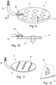
- Fig. 1 a schematic representation of a device according to the invention
- Fig. 2 the arrangement of needle electrodes on a human ear with a representation of voltage and current for vagus nerve stimulation
- Fig. 3 a schematic representation of an electrode array according to the invention
- Fig. 4 a view of an exemplary shape of an electrode
- Fig. 5 a schematic representation of an electrode array with an electrical connection for a stimulation current line
- Fig. 6 an alternative design of an electrode array
- Fig. 7 a detailed view of an electrode attachment
- Fig. 8 an alternative design of the electrode attachment
- Fig. 9 another alternative design of an electrode array
- Fig. 10 a section along the line AA of the Fig. 9, Fig. 11 another alternative design of an electrode array
- Fig. 12 a detailed view of an electrode of the electrode array of Fig. 11 .
- the current generator 1, the measuring circuit 8, the signal processing circuit 9 and the control circuit 10 are arranged in a housing 11 which is located near the ear, e.g., behind the ear.
- the current generator 1, the measuring circuit 8, the signal processing circuit 9, and the control circuit 10 can be designed as separate units or implemented in a common electronic circuit.
- Fig. 2 shows the human ear 12 with blood vessels and the afferent vagus nerve branches 13.
- the electrode arrays 5, 6 and 7 are inserted into the tissue, whereby a sequence of stimulation pulses with the current i 1 is introduced via lead 2 and a sequence of stimulation pulses with the current i 2 is introduced via lead 3 and the current return i 1 +i 2 occurs via lead 4.
- a constant voltage can be impressed and the current measured.
- Fig. 3 shows an electrode array 5, wherein the electrode arrays 6 and 7 can be constructed similarly.
- the electrode array 5 comprises a plate-shaped carrier 14, on which a plurality of needle electrodes 15 are arranged in a grid.
- the needle electrodes 15 have a length x, measured from the skin-facing surface 16 of the carrier 14, of 0.2-0.6 mm, for example, and penetrate the skin surface of a patient.
- the needle electrodes 15 are conical.
- Fig. 4 shows an alternative form of a needle electrode 15, which forms an independent subject of the present invention.
- the needle electrode can be used either as part of an electrode array 5 or as a single needle.
- the needle electrode 15 comprises a substantially cylindrical base portion 17, a thickened central portion 18, and a conically tapered needle portion 19 with a needle tip 20.
- Fig. 5 shows an electrode array 5 of the Fig. 3 shown type with a carrier 14 and only schematically indicated needle electrodes 15.
- a line connection is provided which serves to electrically connect a stripped end 23 of a current conductor 22 to the electrode array 5.
- the line connection has a substantially cylindrical connecting part 25 which is arranged on the carrier 14.
- an annular clamping part 24 is attached to the end 23, e.g. by soldering or by injection molding the clamping part made of conductive plastic. The clamping part is pushed over the cylindrical connecting part 25 and fastened, e.g.
- the cable connection can then be provided with a cover, sheath or encapsulation 21, which can be produced from a plastic, for example, by overmolding.
- the current conductor 22 is connected to the electrode array 5 by fastening it to one of the needle electrodes 15.
- the fastening can be done, for example, by clamping, riveting or welding, depending on how the individual needle electrodes 15 are fastened to the carrier 14.
- the needle electrodes 15 are riveted to the support 14.
- the current conductor 22 can be clamped between the thickened head of the needle electrode 15 and the support 14.
- the needle electrodes 15 are welded to the carrier 14.
- the current conductor 22 can be connected to the needle electrode 15 or the carrier 14 by means of a welding point.
- the current conductor 22 is electrically connected to the carrier 14 at a separate fastening point 26.
- the fastening can be effected, for example, by means of a clamping pin.
- Figs. 11 and 12 show an alternative embodiment of the electrode array 5, in which the needle electrodes 15 are formed integrally with the carrier 14 and were bent out of the plate-shaped carrier 14 by punching.
- the current conductor 22 can be directly embossed during the punching process.
Landscapes
- Health & Medical Sciences (AREA)
- Life Sciences & Earth Sciences (AREA)
- Animal Behavior & Ethology (AREA)
- General Health & Medical Sciences (AREA)
- Engineering & Computer Science (AREA)
- Biomedical Technology (AREA)
- Nuclear Medicine, Radiotherapy & Molecular Imaging (AREA)
- Radiology & Medical Imaging (AREA)
- Veterinary Medicine (AREA)
- Public Health (AREA)
- Heart & Thoracic Surgery (AREA)
- Biophysics (AREA)
- Cardiology (AREA)
- Neurology (AREA)
- Neurosurgery (AREA)
- Orthopedic Medicine & Surgery (AREA)
- Electrotherapy Devices (AREA)
Claims (12)
- Réseau d'électrodes pour la stimulation nerveuse périphérique, en particulier pour la stimulation ponctuelle auriculaire, par exemple du nerf vague, comprenant un support en forme de plaque (14) et une pluralité d'électrodes en forme d'aiguille (15) en saillie du support (14), et au moins une connexion électrique reliée de manière conductrice aux électrodes (15) ou à un sous-groupe d'électrodes (15) pour la connexion électrique avec un dispositif de stimulation, les électrodes (15) ayant une longueur maximale de 0,6 mm, de préférence 0,4 à 0,6 mm, les électrodes (15) présentant dans une région centrale un épaississement (18) notamment cylindrique, suivi d'une pointe conique (19, 20), caractérisé en ce que l'épaississement (18) se transforme de manière continue dans la direction du support (14) en une section de base (17) notamment cylindrique, dont le diamètre est inférieur au diamètre de l'épaississement (18).
- Réseau d'électrodes selon la revendication 1, caractérisé en ce que les électrodes (15) sont disposées dans une grille régulière sur le support (14).
- Réseau d'électrodes selon la revendication 1 ou 2, caractérisé en ce que les électrodes (15) sont disposées à une distance de 0,5 à 1 mm les unes des autres.
- Réseau d'électrodes selon l'une des revendications 1 à 3, caractérisé en ce que la pointe d'aiguille (20) des électrodes présente un diamètre de 0,02 à 0,04 mm.
- Réseau d'électrodes selon l'une des revendications 1 à 4, caractérisé en ce que les électrodes (15) comprennent au moins un premier et un deuxième groupe d'électrodes (15), chaque groupe d'électrodes étant relié de manière électriquement conductrice à sa propre connexion électrique.
- Réseau d'électrodes selon l'une des revendications 1 à 5, caractérisé en ce que le réseau d'électrodes (5) est constitué d'un matériau électriquement conducteur, tel que le titane ou le platine-iridium, ou d'un plastique conducteur, tel que le poly-3,4-éthylènedioxythiophène.
- Réseau d'électrodes selon l'une des revendications 1 à 5, caractérisé en ce que les électrodes (15) sont constituées d'un matériau électriquement conducteur, tel que le titane ou le platine-iridium, ou d'un plastique conducteur, tel que le poly-3,4-éthylènedioxythiophène, et le support (14) est constitué d'un matériau électriquement non conducteur, en particulier un polymère.
- Réseau d'électrodes selon l'une des revendications 1 à 5, caractérisé en ce que le réseau d'électrodes (5) est constitué d'un matériau électriquement non conducteur et les électrodes (15) sont pourvues d'un revêtement électriquement conducteur.
- Réseau d'électrodes selon l'une des revendications 1 à 8, caractérisé en ce que le support (14) est conçu comme un film flexible ou une tôle.
- Électrode pour la stimulation nerveuse périphérique, en particulier pour la stimulation ponctuelle auriculaire, par exemple du nerf vague, l'électrode (15) présentant dans une région centrale un épaississement (18) notamment cylindrique, suivi d'une pointe conique (19, 20), caractérisée en ce que l'électrode comprend une section de base (17) notamment cylindrique, dont le diamètre est inférieur à celui de la région centrale épaissie (18) et l'épaississement (18) se transforme de manière continue en la section de base (17) notamment cylindrique.
- Dispositif pour la stimulation nerveuse périphérique, en particulier pour la stimulation ponctuelle auriculaire, par exemple du nerf vague d'un patient, comprenant un générateur de courant (1) pour générer des impulsions de courant de stimulation et au moins un réseau d'électrodes (5, 6, 7) selon l'une des revendications 1 à 9 ou au moins deux électrodes (15) selon la revendication 10, ledit ou lesdits réseaux étant connecté(s) au générateur de courant (1) par au moins une ligne électrique respective (2, 3, 4).
- Dispositif selon la revendication 11, caractérisé en ce que le générateur de courant (1) est conçu pour générer les impulsions de courant de stimulation avec une fréquence d'impulsion inférieure à 1 kHz et avec une amplitude de courant supérieure à 5 mA.
Applications Claiming Priority (2)
| Application Number | Priority Date | Filing Date | Title |
|---|---|---|---|
| EP22020150.3A EP4257175A1 (fr) | 2022-04-04 | 2022-04-04 | Réseau d'électrodes et électrode pour la stimulation des nerfs périphériques |
| PCT/IB2023/053189 WO2023194853A1 (fr) | 2022-04-04 | 2023-03-30 | Réseau d'électrodes et électrode pour stimulation de nerf périphérique |
Publications (3)
| Publication Number | Publication Date |
|---|---|
| EP4504331A1 EP4504331A1 (fr) | 2025-02-12 |
| EP4504331C0 EP4504331C0 (fr) | 2025-07-02 |
| EP4504331B1 true EP4504331B1 (fr) | 2025-07-02 |
Family
ID=81327367
Family Applications (2)
| Application Number | Title | Priority Date | Filing Date |
|---|---|---|---|
| EP22020150.3A Withdrawn EP4257175A1 (fr) | 2022-04-04 | 2022-04-04 | Réseau d'électrodes et électrode pour la stimulation des nerfs périphériques |
| EP23718357.9A Active EP4504331B1 (fr) | 2022-04-04 | 2023-03-30 | Réseau d'électrodes et électrode pour la stimulation des nerfs périphériques |
Family Applications Before (1)
| Application Number | Title | Priority Date | Filing Date |
|---|---|---|---|
| EP22020150.3A Withdrawn EP4257175A1 (fr) | 2022-04-04 | 2022-04-04 | Réseau d'électrodes et électrode pour la stimulation des nerfs périphériques |
Country Status (4)
| Country | Link |
|---|---|
| US (1) | US20260041909A1 (fr) |
| EP (2) | EP4257175A1 (fr) |
| ES (1) | ES3037512T3 (fr) |
| WO (1) | WO2023194853A1 (fr) |
Families Citing this family (2)
| Publication number | Priority date | Publication date | Assignee | Title |
|---|---|---|---|---|
| DE102023129520A1 (de) * | 2023-10-26 | 2025-04-30 | Biolitec Unternehmensbeteiligungs Iii Ag | Nadeleinrichtung zur Platzierung an einer Ohrmuschel, Nervenstimulationsvorrichtung zum elektrischen Stimulieren zumindest eines Nervs und Verfahren zur Verwendung einer Nadeleinrichtung |
| DE102023129519A1 (de) * | 2023-10-26 | 2025-04-30 | biolitec Unternehmensbeteiligungs llI AG | Nervenstimulationsvorrichtung zum elektrischen Stimulieren zumindest eines Nervs, zumindest einer Ohrmuschel und/oder zumindest eines Ohrläppchens |
Family Cites Families (7)
| Publication number | Priority date | Publication date | Assignee | Title |
|---|---|---|---|---|
| US5324287A (en) * | 1988-11-21 | 1994-06-28 | Szeles Josef C | Needle and therapeutic device for stimulating specific points of the body |
| SE9201453L (sv) * | 1992-05-08 | 1993-07-12 | Jens Schouenborg | Medicinsk anordning foer lindring av smaerttillstaand innefattande en elektrodplatta |
| EP1164928B1 (fr) * | 2000-01-21 | 2005-06-01 | Instrumentarium Corporation | Methode de fabrication d'une electrode medicale |
| EP1809370B1 (fr) * | 2004-10-19 | 2017-08-02 | Meagan Medical, Inc. | Elements de stimulation electrique de recepteurs sensoriels cutanes |
| AT11955U1 (de) | 2009-09-14 | 2011-08-15 | Muw Forschungsservice Und Beteiligungs Gmbh | Gerät zur punktual-stimulation |
| EP3331603A4 (fr) * | 2015-08-06 | 2019-01-23 | The Regents of The University of California | Procédés de fabrication de réseau d'électrodes pour la stimulation électrique transcutanée de moelle épinière |
| CA2998518A1 (fr) * | 2015-09-11 | 2017-03-16 | Arturo C. Taca, Jr. | Traitement de l'addiction et de la dependance |
-
2022
- 2022-04-04 EP EP22020150.3A patent/EP4257175A1/fr not_active Withdrawn
-
2023
- 2023-03-30 EP EP23718357.9A patent/EP4504331B1/fr active Active
- 2023-03-30 ES ES23718357T patent/ES3037512T3/es active Active
- 2023-03-30 US US18/853,688 patent/US20260041909A1/en active Pending
- 2023-03-30 WO PCT/IB2023/053189 patent/WO2023194853A1/fr not_active Ceased
Also Published As
| Publication number | Publication date |
|---|---|
| EP4257175A1 (fr) | 2023-10-11 |
| EP4504331C0 (fr) | 2025-07-02 |
| ES3037512T3 (en) | 2025-10-02 |
| WO2023194853A1 (fr) | 2023-10-12 |
| US20260041909A1 (en) | 2026-02-12 |
| EP4504331A1 (fr) | 2025-02-12 |
Similar Documents
| Publication | Publication Date | Title |
|---|---|---|
| DE3502913C1 (de) | Messaufnehmer zur nichtinvasiven Erfassung elektrophysiologischer Groessen | |
| EP0444097B1 (fr) | Aiguille et dispositif therapeutique pour stimuler des points specifiques du corps | |
| DE60124021T2 (de) | Implantierbare Stimulationsleitung | |
| DE69425728T2 (de) | Medizinische elektroden-anordnung | |
| EP1878462B1 (fr) | Dispositif d'introduction | |
| DE102015017269B3 (de) | Elektronisches Stimulationssystem und Vorrichtung davon für Spinalganglion | |
| EP4504331B1 (fr) | Réseau d'électrodes et électrode pour la stimulation des nerfs périphériques | |
| EP2575731B1 (fr) | Ensemble d'électrodes | |
| DE69304035T2 (de) | Medizinische vorrichtung | |
| DE4402058C1 (de) | Implantierbares, passageres Elektrodenkabel | |
| AT11956U1 (de) | Elektrisches stimulationsgerät | |
| EP2744561B1 (fr) | Dispositif d'application d'une thérapie par radiofréquence pulsée dans le système vasculaire ou d'autres cavités corporelles du corps humain ou animal | |
| EP3145581B1 (fr) | Dispositif multicanaux de fourniture de courant continu utilisable à des fins thérapeutiques | |
| DE3213331A1 (de) | Poroese elektrodenspitze fuer herzschrittmacher und verfahren zum herstellen derselben | |
| EP2026872A1 (fr) | Dispositif d'application transcutanée d'un stimulus ou de détection transcutanée d'un paramètre | |
| EP0346513A1 (fr) | Ensemble pour électrothérapie | |
| EP1260186B1 (fr) | Ensemble aiguille pour le blocage des nerfs périphériques | |
| EP3784327B1 (fr) | Corps d'électrode d'un ensemble d'électrodes et ensemble d'électrodes de stimulation électrique et procédé de fabrication d'un ensemble d'électrodes | |
| EP2944281A1 (fr) | Elément d'électrode destiné à la thérapie électromédicale dans un corps humain ou d'animal | |
| EP2865411A1 (fr) | Dispositif de stimulation | |
| DE102021102864B3 (de) | Federkontaktring | |
| DE2643130C2 (de) | Akupunktur-Elektrode | |
| DE102007012474B4 (de) | Elektrotherapiegerät | |
| DE8502291U1 (de) | Meßaufnehmer für biomedizinische Signale | |
| WO2020210849A1 (fr) | Électrode |
Legal Events
| Date | Code | Title | Description |
|---|---|---|---|
| STAA | Information on the status of an ep patent application or granted ep patent |
Free format text: STATUS: UNKNOWN |
|
| STAA | Information on the status of an ep patent application or granted ep patent |
Free format text: STATUS: THE INTERNATIONAL PUBLICATION HAS BEEN MADE |
|
| PUAI | Public reference made under article 153(3) epc to a published international application that has entered the european phase |
Free format text: ORIGINAL CODE: 0009012 |
|
| STAA | Information on the status of an ep patent application or granted ep patent |
Free format text: STATUS: REQUEST FOR EXAMINATION WAS MADE |
|
| 17P | Request for examination filed |
Effective date: 20241022 |
|
| AK | Designated contracting states |
Kind code of ref document: A1 Designated state(s): AL AT BE BG CH CY CZ DE DK EE ES FI FR GB GR HR HU IE IS IT LI LT LU LV MC ME MK MT NL NO PL PT RO RS SE SI SK SM TR |
|
| GRAP | Despatch of communication of intention to grant a patent |
Free format text: ORIGINAL CODE: EPIDOSNIGR1 |
|
| STAA | Information on the status of an ep patent application or granted ep patent |
Free format text: STATUS: GRANT OF PATENT IS INTENDED |
|
| DAV | Request for validation of the european patent (deleted) | ||
| DAX | Request for extension of the european patent (deleted) | ||
| INTG | Intention to grant announced |
Effective date: 20250214 |
|
| GRAS | Grant fee paid |
Free format text: ORIGINAL CODE: EPIDOSNIGR3 |
|
| GRAA | (expected) grant |
Free format text: ORIGINAL CODE: 0009210 |
|
| STAA | Information on the status of an ep patent application or granted ep patent |
Free format text: STATUS: THE PATENT HAS BEEN GRANTED |
|
| AK | Designated contracting states |
Kind code of ref document: B1 Designated state(s): AL AT BE BG CH CY CZ DE DK EE ES FI FR GB GR HR HU IE IS IT LI LT LU LV MC ME MK MT NL NO PL PT RO RS SE SI SK SM TR |
|
| REG | Reference to a national code |
Ref country code: GB Ref legal event code: FG4D Free format text: NOT ENGLISH |
|
| RIN1 | Information on inventor provided before grant (corrected) |
Inventor name: KAMPUSCH, STEFAN |
|
| REG | Reference to a national code |
Ref country code: CH Ref legal event code: EP |
|
| REG | Reference to a national code |
Ref country code: HK Ref legal event code: DE Ref document number: 40119531 Country of ref document: HK |
|
| REG | Reference to a national code |
Ref country code: DE Ref legal event code: R096 Ref document number: 502023001281 Country of ref document: DE |
|
| REG | Reference to a national code |
Ref country code: IE Ref legal event code: FG4D Free format text: LANGUAGE OF EP DOCUMENT: GERMAN |
|
| U01 | Request for unitary effect filed |
Effective date: 20250702 |
|
| U07 | Unitary effect registered |
Designated state(s): AT BE BG DE DK EE FI FR IT LT LU LV MT NL PT RO SE SI Effective date: 20250709 |
|
| REG | Reference to a national code |
Ref country code: ES Ref legal event code: FG2A Ref document number: 3037512 Country of ref document: ES Kind code of ref document: T3 Effective date: 20251002 |
|
| PG25 | Lapsed in a contracting state [announced via postgrant information from national office to epo] |
Ref country code: IS Free format text: LAPSE BECAUSE OF FAILURE TO SUBMIT A TRANSLATION OF THE DESCRIPTION OR TO PAY THE FEE WITHIN THE PRESCRIBED TIME-LIMIT Effective date: 20251102 |
|
| PG25 | Lapsed in a contracting state [announced via postgrant information from national office to epo] |
Ref country code: NO Free format text: LAPSE BECAUSE OF FAILURE TO SUBMIT A TRANSLATION OF THE DESCRIPTION OR TO PAY THE FEE WITHIN THE PRESCRIBED TIME-LIMIT Effective date: 20251002 |
|
| PG25 | Lapsed in a contracting state [announced via postgrant information from national office to epo] |
Ref country code: HR Free format text: LAPSE BECAUSE OF FAILURE TO SUBMIT A TRANSLATION OF THE DESCRIPTION OR TO PAY THE FEE WITHIN THE PRESCRIBED TIME-LIMIT Effective date: 20250702 |
|
| PG25 | Lapsed in a contracting state [announced via postgrant information from national office to epo] |
Ref country code: GR Free format text: LAPSE BECAUSE OF FAILURE TO SUBMIT A TRANSLATION OF THE DESCRIPTION OR TO PAY THE FEE WITHIN THE PRESCRIBED TIME-LIMIT Effective date: 20251003 |
|
| PG25 | Lapsed in a contracting state [announced via postgrant information from national office to epo] |
Ref country code: CZ Free format text: LAPSE BECAUSE OF FAILURE TO SUBMIT A TRANSLATION OF THE DESCRIPTION OR TO PAY THE FEE WITHIN THE PRESCRIBED TIME-LIMIT Effective date: 20250702 |
|
| PG25 | Lapsed in a contracting state [announced via postgrant information from national office to epo] |
Ref country code: PL Free format text: LAPSE BECAUSE OF FAILURE TO SUBMIT A TRANSLATION OF THE DESCRIPTION OR TO PAY THE FEE WITHIN THE PRESCRIBED TIME-LIMIT Effective date: 20250702 |
|
| PG25 | Lapsed in a contracting state [announced via postgrant information from national office to epo] |
Ref country code: RS Free format text: LAPSE BECAUSE OF FAILURE TO SUBMIT A TRANSLATION OF THE DESCRIPTION OR TO PAY THE FEE WITHIN THE PRESCRIBED TIME-LIMIT Effective date: 20251002 |