EP4504331B1 - Electrode array and electrode for peripheral nerve stimulation - Google Patents
Electrode array and electrode for peripheral nerve stimulation Download PDFInfo
- Publication number
- EP4504331B1 EP4504331B1 EP23718357.9A EP23718357A EP4504331B1 EP 4504331 B1 EP4504331 B1 EP 4504331B1 EP 23718357 A EP23718357 A EP 23718357A EP 4504331 B1 EP4504331 B1 EP 4504331B1
- Authority
- EP
- European Patent Office
- Prior art keywords
- electrodes
- electrode array
- stimulation
- electrode
- carrier
- Prior art date
- Legal status (The legal status is an assumption and is not a legal conclusion. Google has not performed a legal analysis and makes no representation as to the accuracy of the status listed.)
- Active
Links
Images


Classifications
-
- A—HUMAN NECESSITIES
- A61—MEDICAL OR VETERINARY SCIENCE; HYGIENE
- A61N—ELECTROTHERAPY; MAGNETOTHERAPY; RADIATION THERAPY; ULTRASOUND THERAPY
- A61N1/00—Electrotherapy; Circuits therefor
- A61N1/02—Details
- A61N1/04—Electrodes
- A61N1/05—Electrodes for implantation or insertion into the body, e.g. heart electrode
- A61N1/0551—Spinal or peripheral nerve electrodes
- A61N1/0558—Anchoring or fixation means therefor
-
- A—HUMAN NECESSITIES
- A61—MEDICAL OR VETERINARY SCIENCE; HYGIENE
- A61N—ELECTROTHERAPY; MAGNETOTHERAPY; RADIATION THERAPY; ULTRASOUND THERAPY
- A61N1/00—Electrotherapy; Circuits therefor
- A61N1/02—Details
- A61N1/04—Electrodes
- A61N1/05—Electrodes for implantation or insertion into the body, e.g. heart electrode
- A61N1/0502—Skin piercing electrodes
-
- A—HUMAN NECESSITIES
- A61—MEDICAL OR VETERINARY SCIENCE; HYGIENE
- A61N—ELECTROTHERAPY; MAGNETOTHERAPY; RADIATION THERAPY; ULTRASOUND THERAPY
- A61N1/00—Electrotherapy; Circuits therefor
- A61N1/02—Details
- A61N1/04—Electrodes
- A61N1/0404—Electrodes for external use
- A61N1/0472—Structure-related aspects
- A61N1/0476—Array electrodes (including any electrode arrangement with more than one electrode for at least one of the polarities)
-
- A—HUMAN NECESSITIES
- A61—MEDICAL OR VETERINARY SCIENCE; HYGIENE
- A61N—ELECTROTHERAPY; MAGNETOTHERAPY; RADIATION THERAPY; ULTRASOUND THERAPY
- A61N1/00—Electrotherapy; Circuits therefor
- A61N1/18—Applying electric currents by contact electrodes
- A61N1/32—Applying electric currents by contact electrodes alternating or intermittent currents
- A61N1/36—Applying electric currents by contact electrodes alternating or intermittent currents for stimulation
- A61N1/36014—External stimulators, e.g. with patch electrodes
- A61N1/36017—External stimulators, e.g. with patch electrodes with leads or electrodes penetrating the skin
-
- A—HUMAN NECESSITIES
- A61—MEDICAL OR VETERINARY SCIENCE; HYGIENE
- A61N—ELECTROTHERAPY; MAGNETOTHERAPY; RADIATION THERAPY; ULTRASOUND THERAPY
- A61N1/00—Electrotherapy; Circuits therefor
- A61N1/18—Applying electric currents by contact electrodes
- A61N1/32—Applying electric currents by contact electrodes alternating or intermittent currents
- A61N1/36—Applying electric currents by contact electrodes alternating or intermittent currents for stimulation
- A61N1/36014—External stimulators, e.g. with patch electrodes
- A61N1/3603—Control systems
- A61N1/36034—Control systems specified by the stimulation parameters
-
- A—HUMAN NECESSITIES
- A61—MEDICAL OR VETERINARY SCIENCE; HYGIENE
- A61N—ELECTROTHERAPY; MAGNETOTHERAPY; RADIATION THERAPY; ULTRASOUND THERAPY
- A61N1/00—Electrotherapy; Circuits therefor
- A61N1/02—Details
- A61N1/04—Electrodes
- A61N1/05—Electrodes for implantation or insertion into the body, e.g. heart electrode
- A61N1/0551—Spinal or peripheral nerve electrodes
-
- A—HUMAN NECESSITIES
- A61—MEDICAL OR VETERINARY SCIENCE; HYGIENE
- A61N—ELECTROTHERAPY; MAGNETOTHERAPY; RADIATION THERAPY; ULTRASOUND THERAPY
- A61N1/00—Electrotherapy; Circuits therefor
- A61N1/18—Applying electric currents by contact electrodes
- A61N1/32—Applying electric currents by contact electrodes alternating or intermittent currents
- A61N1/36—Applying electric currents by contact electrodes alternating or intermittent currents for stimulation
- A61N1/36036—Applying electric currents by contact electrodes alternating or intermittent currents for stimulation of the outer, middle or inner ear
Definitions
- the invention relates to an electrode array for peripheral nerve stimulation, in particular for auricular punctual stimulation, e.g. of the vagus nerve.
- the invention further relates to an electrode for peripheral nerve stimulation, in particular for auricular punctual stimulation, e.g. of the vagus nerve.
- the invention further relates to a device for peripheral nerve stimulation, in particular for auricular punctual stimulation, e.g. of the vagus nerve of a patient, comprising a current generator for generating stimulation current pulses and at least one electrode array or at least one electrode which is connected to the current generator by means of an electrical line.
- a device for peripheral nerve stimulation in particular for auricular punctual stimulation, e.g. of the vagus nerve of a patient, comprising a current generator for generating stimulation current pulses and at least one electrode array or at least one electrode which is connected to the current generator by means of an electrical line.
- Auricular punctual stimulation devices such as those used in WO 2011/030210 A1
- electrical stimulation pulses are introduced via needle electrodes that are inserted into the skin at predetermined points on the auricle and remain there for the treatment period of, for example, several days.
- stimulation enables beneficial effects on pain processing and perception.
- Stimulation also positively influences the sympathovagal balance in the autonomic nervous system.
- the patient's current physiological state changes dynamically, measured as a change in heart rate. respiratory rate, blood pressure, local blood flow and other parameters.
- the electrode has a support base member from which a plurality of tips protrude in an array on a surface of the base member.
- the tips are long enough to penetrate through the stratum corneum into the stratum germinativum of the person's skin and have a thickened central portion.
- the aim is to reduce the stimulation energy as much as possible in order to achieve a miniaturized design and high energy efficiency of the stimulation devices used.
- the present invention therefore aims to overcome the above disadvantages and to provide an electrode arrangement for peripheral nerve stimulation that allows for locally specific stimulation, enables long-term treatment, increases wearing comfort, and minimizes the required stimulation energy. Furthermore, the invention aims to improve an electrode array or a single electrode by improving its retention in the tissue and increasing its resistance to withdrawal or falling out.
- the invention is therefore based on the approach of using an electrode array, instead of a single long needle or a surface electrode, comprising a plurality of short electrodes that penetrate the tissue, but to a limited extent.
- the electrodes have a maximum length of 0.6 mm, preferably 0.4-0.6 mm, with the length of the electrodes being understood as the distance between the needle tip and the surface of the plate-shaped carrier that defines the skin contact area.
- the electrode length can therefore be equated with the maximum penetration depth of the electrodes into a patient's skin.
- the electrode array according to the invention can be made of a wide variety of materials.
- the electrode array consists essentially entirely of an electrically conductive material, in particular a metal such as titanium or platinum-iridium, or a conductive plastic such as poly-3,4-ethylenedioxythiophene.
- At least the electrodes consist of an electrically conductive material, such as titanium or platinum-iridium or of a conductive plastic, such as poly-3,4-ethylenedioxythiophene, and the carrier consists of an electrically non-conductive material, in particular a polymer.
- the electrode array may be made of an electrically non-conductive material, and the electrodes may be provided with an electrically conductive coating, e.g., made of gold or titanium.
- the coating may be applied by any coating method. such as sputtering or electroplating.
- the electrode array can be manufactured by milling from a solid body, by a casting process such as injection molding, by punching from a plate, or by an additive manufacturing process (3D printing). Additive manufacturing can be performed, for example, using a stereolithographic printing process, which allows for high spatial resolution and the production of the electrodes with corresponding precision, exact dimensions, and a smooth surface.
- the electrode array can be printed, for example, from a conductive plastic or from a metallic and therefore electrically conductive material. Alternatively, the electrode array can be printed from a non-conductive material and then coated with a conductive material.
- the plate-like carrier of the electrode array according to the invention can be designed as a rigid carrier or as a flexible structure, such as a film or sheet metal.
- the carrier can be designed as a conductive gel pad (e.g. conductive hydrogel) that is pierced with the electrode needles, thus forming a flexible electrode.
- the design as a flexible structure allows easy adaptation of the carrier to the respective surface contour of the body site to which the electrode array is to be applied.
- the carrier can provide a skin contact surface from which the electrodes protrude, which is flat.
- the skin contact surface of the carrier can be shaped to fit the desired body site.
- the skin contact surface of the carrier may be provided with an adhesive coating.
- the electrode arrays according to the invention can be used, each connected to its own stimulation channel of an associated stimulation device.
- the electrode array according to the invention can also be formed and used as a larger-area matrix that supports multiple stimulation channels. In this way, bipolar and monophasic, biphasic, or multiphasic stimulation can be achieved.
- the electrodes have at least a first and a second group of electrodes, each group of electrodes being electrically connected to its own electrical connection.
- a device for peripheral nerve stimulation in particular for auricular punctual stimulation, e.g. of the vagus nerve of a patient, comprising a current generator for generating stimulation current pulses and at least one electrode array according to the first aspect of the invention or at least two electrodes according to the second aspect of the invention, which is or are connected to the current generator by at least one electrical line each.
- Fig. 1 a schematic representation of a device according to the invention
- Fig. 2 the arrangement of needle electrodes on a human ear with a representation of voltage and current for vagus nerve stimulation
- Fig. 3 a schematic representation of an electrode array according to the invention
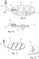
- Fig. 4 a view of an exemplary shape of an electrode
- Fig. 5 a schematic representation of an electrode array with an electrical connection for a stimulation current line
- Fig. 6 an alternative design of an electrode array
- Fig. 7 a detailed view of an electrode attachment
- Fig. 8 an alternative design of the electrode attachment
- Fig. 9 another alternative design of an electrode array
- Fig. 10 a section along the line AA of the Fig. 9, Fig. 11 another alternative design of an electrode array
- Fig. 12 a detailed view of an electrode of the electrode array of Fig. 11 .
- the current generator 1, the measuring circuit 8, the signal processing circuit 9 and the control circuit 10 are arranged in a housing 11 which is located near the ear, e.g., behind the ear.
- the current generator 1, the measuring circuit 8, the signal processing circuit 9, and the control circuit 10 can be designed as separate units or implemented in a common electronic circuit.
- Fig. 2 shows the human ear 12 with blood vessels and the afferent vagus nerve branches 13.
- the electrode arrays 5, 6 and 7 are inserted into the tissue, whereby a sequence of stimulation pulses with the current i 1 is introduced via lead 2 and a sequence of stimulation pulses with the current i 2 is introduced via lead 3 and the current return i 1 +i 2 occurs via lead 4.
- a constant voltage can be impressed and the current measured.
- Fig. 3 shows an electrode array 5, wherein the electrode arrays 6 and 7 can be constructed similarly.
- the electrode array 5 comprises a plate-shaped carrier 14, on which a plurality of needle electrodes 15 are arranged in a grid.
- the needle electrodes 15 have a length x, measured from the skin-facing surface 16 of the carrier 14, of 0.2-0.6 mm, for example, and penetrate the skin surface of a patient.
- the needle electrodes 15 are conical.
- Fig. 4 shows an alternative form of a needle electrode 15, which forms an independent subject of the present invention.
- the needle electrode can be used either as part of an electrode array 5 or as a single needle.
- the needle electrode 15 comprises a substantially cylindrical base portion 17, a thickened central portion 18, and a conically tapered needle portion 19 with a needle tip 20.
- Fig. 5 shows an electrode array 5 of the Fig. 3 shown type with a carrier 14 and only schematically indicated needle electrodes 15.
- a line connection is provided which serves to electrically connect a stripped end 23 of a current conductor 22 to the electrode array 5.
- the line connection has a substantially cylindrical connecting part 25 which is arranged on the carrier 14.
- an annular clamping part 24 is attached to the end 23, e.g. by soldering or by injection molding the clamping part made of conductive plastic. The clamping part is pushed over the cylindrical connecting part 25 and fastened, e.g.
- the cable connection can then be provided with a cover, sheath or encapsulation 21, which can be produced from a plastic, for example, by overmolding.
- the current conductor 22 is connected to the electrode array 5 by fastening it to one of the needle electrodes 15.
- the fastening can be done, for example, by clamping, riveting or welding, depending on how the individual needle electrodes 15 are fastened to the carrier 14.
- the needle electrodes 15 are riveted to the support 14.
- the current conductor 22 can be clamped between the thickened head of the needle electrode 15 and the support 14.
- the needle electrodes 15 are welded to the carrier 14.
- the current conductor 22 can be connected to the needle electrode 15 or the carrier 14 by means of a welding point.
- the current conductor 22 is electrically connected to the carrier 14 at a separate fastening point 26.
- the fastening can be effected, for example, by means of a clamping pin.
- Figs. 11 and 12 show an alternative embodiment of the electrode array 5, in which the needle electrodes 15 are formed integrally with the carrier 14 and were bent out of the plate-shaped carrier 14 by punching.
- the current conductor 22 can be directly embossed during the punching process.
Landscapes
- Health & Medical Sciences (AREA)
- Life Sciences & Earth Sciences (AREA)
- Animal Behavior & Ethology (AREA)
- General Health & Medical Sciences (AREA)
- Engineering & Computer Science (AREA)
- Biomedical Technology (AREA)
- Nuclear Medicine, Radiotherapy & Molecular Imaging (AREA)
- Radiology & Medical Imaging (AREA)
- Veterinary Medicine (AREA)
- Public Health (AREA)
- Heart & Thoracic Surgery (AREA)
- Biophysics (AREA)
- Cardiology (AREA)
- Neurology (AREA)
- Neurosurgery (AREA)
- Orthopedic Medicine & Surgery (AREA)
- Electrotherapy Devices (AREA)
Description
Die Erfindung betrifft ein Elektrodenarray für die periphere Nervenstimulation, insbesondere für die aurikuläre Punktualstimulation z.B. des Vagusnervs.The invention relates to an electrode array for peripheral nerve stimulation, in particular for auricular punctual stimulation, e.g. of the vagus nerve.
Die Erfindung betrifft weiters eine Elektrode für die periphere Nervenstimulation, insbesondere für die aurikuläre Punktualstimulation z.B. des Vagusnervs.The invention further relates to an electrode for peripheral nerve stimulation, in particular for auricular punctual stimulation, e.g. of the vagus nerve.
Die Erfindung betrifft weiters eine Vorrichtung zur peripheren Nervenstimulation, insbesondere zur aurikulären Punktualstimulation z.B. des Vagusnervs eines Patienten, umfassend einen Stromgenerator zur Erzeugung von Stimulationsstromimpulsen und wenigstens ein Elektrodenarray oder wenigstens eine Elektrode, das bzw. die mittels einer elektrischen Leitung mit dem Stromgenerator verbunden ist.The invention further relates to a device for peripheral nerve stimulation, in particular for auricular punctual stimulation, e.g. of the vagus nerve of a patient, comprising a current generator for generating stimulation current pulses and at least one electrode array or at least one electrode which is connected to the current generator by means of an electrical line.
Verfügbare Stimulationsgeräte für die elektrische Stimulation des aurikulären Vagusnervs werden in der Therapie verschiedenster Erkrankungen, wie z.B. chronischer und akuter Schmerzen, Epilepsie und Depression, eingesetzt. Bei aurikulären Punktualstimulationsgeräten, wie sie z.B. aus der
Die Stimulation ermöglicht zum Beispiel die vorteilhafte Beeinflussung von Schmerzverarbeitung und Schmerzwahrnehmung. Auch wird durch die Stimulation die sympathovagale Balance im autonomen Nervensystem positiv beeinflusst. In der Folge verändert sich der aktuelle physiologische Zustand des Patienten dynamisch, gemessen als Veränderung der Herzrate, der Atemrate, des Blutdrucks, der lokalen Durchblutung und anderer Parameter.For example, stimulation enables beneficial effects on pain processing and perception. Stimulation also positively influences the sympathovagal balance in the autonomic nervous system. As a result, the patient's current physiological state changes dynamically, measured as a change in heart rate. respiratory rate, blood pressure, local blood flow and other parameters.
Stimulationsgeräte für periphere Nervenstimulation verwenden zumeist Oberflächenelektroden. Dabei handelt es sich z.B. um Ballelektroden, die auf der Haut anliegen oder durch mechanische Passung, z.B. mit der Form der Ohrmuschel, an die Haut angepresst werden. Im Anwendungsbereich der transkutanen Nervenstimulation gibt es auch Klebeelektroden, die meist großflächig auf den zu stimulierenden Hautbereich aufgeklebt werden. Die Stimulation erfolgt so über einen größeren Hautbereich, da die Elektroden eine gewisse Größe aufweisen müssen, um keine Verbrennungen zu verursachen, da hohe Stimulationsenergien verwendet werden müssen, um den Hautwiderstand zu überwinden. Eine Fixierung der Elektroden, abgesehen von Klebeelektroden, ist hier oft schwierig und beschränkt die Anwendung meist auf eine intermittierende, nicht chronische Anwendung. Ein weiterer Nachteil großflächiger Oberflächenelektroden liegt in der örtlich unspezifischen Stimulation.Stimulation devices for peripheral nerve stimulation usually use surface electrodes. These are, for example, ball electrodes that rest on the skin or are pressed against it by mechanical means, e.g., conforming to the shape of the auricle. In the field of transcutaneous nerve stimulation, adhesive electrodes are also used, which are usually applied over a large area of the skin to be stimulated. Stimulation is thus delivered over a larger area of skin, as the electrodes must be a certain size to avoid burns, as high stimulation energies must be used to overcome skin resistance. Fixing the electrodes, with the exception of adhesive electrodes, is often difficult and usually limits their use to intermittent, non-chronic application. Another disadvantage of large-area surface electrodes is the non-specific local stimulation.
Andererseits gibt es Anwendungen der perkutanen Stimulation, wo mittels kleiner Nadelelektroden bis zu 2 mm tief in die Haut eingestochen wird, um dort Nervenfasern zu reizen. Mit solchen Nadelelektroden kann man sehr spezifisch stimulieren und überwindet den Hautwiderstand mit resultierender niedrigerer Stimulationsenergie im Vergleich zu Oberflächenelektroden, da der Hautwiderstand nicht mehr relevant ist. Auch hier ist die Fixierung nicht einfach, aber leichter möglich als bei Oberflächenelektroden, was eine chronische Anwendung über mehrere Tage prinzipiell erlaubt. Allerdings schmerzen längere Nadelelektroden beim Einstechen und können teilweise nur schwer für längere Dauer fixiert werden. Das meist elastische Gewebe drückt die Nadelelektroden mit der Zeit wieder aus dem Gewebe heraus. Die
Grundsätzlich ist man bestrebt, die Stimulationsenergie möglichst zu reduzieren, um eine miniaturisierte Bauweise und eine hohe Energieeffizienz von eingesetzten Stimulationsgeräten zu erzielen.In principle, the aim is to reduce the stimulation energy as much as possible in order to achieve a miniaturized design and high energy efficiency of the stimulation devices used.
Die vorliegende Erfindung zielt daher darauf ab, die obigen Nachteile zu überwinden und eine Elektrodenanordnung für die periphere Nervenstimulation zu schaffen, die eine örtlich spezifische Stimulation erlaubt, eine langfristige Behandlung ermöglicht, den Tragekomfort erhöht und die erforderliche Stimulationsenergie minimiert. Weiters zielt die Erfindung darauf ab, ein Elektrodenarray oder eine einzelne Elektrode dahingehend zu verbessern, dass dessen bzw. deren Halt im Gewebe verbessert und dessen bzw. deren Widerstand gegen ein Herausziehen oder Herausfallen erhöht wird.The present invention therefore aims to overcome the above disadvantages and to provide an electrode arrangement for peripheral nerve stimulation that allows for locally specific stimulation, enables long-term treatment, increases wearing comfort, and minimizes the required stimulation energy. Furthermore, the invention aims to improve an electrode array or a single electrode by improving its retention in the tissue and increasing its resistance to withdrawal or falling out.
Zur Lösung dieser Aufgabe besteht die Erfindung in der Bereitstellung eines Elektrodenarrays gemäß Anspruch 1.To achieve this object, the invention consists in providing an electrode array according to
Die Erfindung beruht somit auf dem Ansatz, anstelle einer einzelnen langen Nadel oder einer Oberflächenelektrode ein Elektrodenarray zu verwenden, das eine Mehrzahl von kurzen Elektroden aufweist, die zwar in das Gewebe eindringen, dies jedoch in einem begrenzten Ausmaß. Die Elektroden weisen hierbei eine maximale Länge von 0,6mm, bevorzugt 0,4-0,6mm, auf, wobei unter der Länge der Elektroden der Abstand zwischen der Nadelspitze und der die Hautauflagefläche definierenden Oberfläche des plattenförmigen Trägers zu verstehen ist. Die Elektrodenlänge kann daher mit der maximalen Eindringtiefe der Elektroden in die Haut eines Patienten gleichgesetzt werden.The invention is therefore based on the approach of using an electrode array, instead of a single long needle or a surface electrode, comprising a plurality of short electrodes that penetrate the tissue, but to a limited extent. The electrodes have a maximum length of 0.6 mm, preferably 0.4-0.6 mm, with the length of the electrodes being understood as the distance between the needle tip and the surface of the plate-shaped carrier that defines the skin contact area. The electrode length can therefore be equated with the maximum penetration depth of the electrodes into a patient's skin.
So können die Stimulationsimpulse einerseits ortsspezifisch eingebracht werden und es kann andererseits die Stimulationsenergie niedrig gehalten werden. Weiters wird die Invasivität im Vergleich zu langen Nadelelektroden reduziert. Die Aufbauhöhe kann dadurch stark reduziert und damit die mechanische Stabilität erhöht werden. Des Weiteren führen mehrere kleine Nadelelektroden zu einem besseren Sitz im Gewebe. Schmerzen beim Einstechen werden nahezu vollständig verhindert. Der Tragekomfort wird wesentlich erhöht. Für die chronische Anwendung über mehrere Tage ist die Fixierung der Elektroden wesentlich einfacher möglich.This allows the stimulation pulses to be delivered to a specific location, while keeping the stimulation energy low. Furthermore, invasiveness is reduced compared to long needle electrodes. The installation height can be significantly reduced, thus increasing mechanical stability. Furthermore, multiple small needle electrodes result in a better fit in the tissue. Pain during insertion is almost completely eliminated. Wearer comfort is significantly increased. For chronic use over several days, fixation of the electrodes is much easier.
Auf Grund der niedrigeren Stimulationsenergie und der erhöhten Oberfläche durch multiple Nadeln ist weiters die Gefahr reduziert, im Betrieb diejenige Stromdichte ("Charge Injection Limit") an der Elektrode zu überschreiten, unterhalb der die Stimulationspulse keine Reaktionsprodukte erzeugen und sohin keine Korrosionsprozesse an der Elektrode stattfinden lassen.Due to the lower stimulation energy and the increased surface area due to multiple needles, the risk of exceeding the current density ("charge injection limit") at the electrode during operation is also reduced. Below this level, the stimulation pulses do not generate reaction products and thus do not allow corrosion processes to occur at the electrode.
Hinsichtlich der Anordnung der Elektroden auf dem plattenförmigen Träger sind grundsätzliche keine Einschränkungen vorgesehen. Eine möglichst gleichmäßige Verteilung der Stimulationsenergie über den vom Elektrodenarray abgedeckten Bereich des Gewebes gelingt gemäß einer bevorzugten Ausbildung der Erfindung jedoch dadurch, dass die Elektroden in einem regelmäßigen Raster auf dem Träger angeordnet sind.There are basically no restrictions regarding the arrangement of the electrodes on the plate-shaped carrier. However, according to a preferred embodiment of the invention, the most even distribution of the stimulation energy across the area of tissue covered by the electrode array is achieved by arranging the electrodes in a regular grid on the carrier.
Bevorzugt sind die Elektroden in einem Abstand von 0,5-1mm voneinander angeordnet, wobei hier jeweils der kürzeste Abstand zwischen zwei benachbarten Elektroden herangezogen wird.Preferably, the electrodes are arranged at a distance of 0.5-1 mm from each other, whereby the shortest distance between two adjacent electrodes is used.
Das Elektrodenarray kann mindestens drei Elektroden umfassen. Bevorzugt umfasst das Elektrodenarray mindestens 9, bevorzugt mindestens 16, bevorzugt mindestens 25 Elektroden.The electrode array may comprise at least three electrodes. Preferably, the electrode array comprises at least 9, preferably at least 16, preferably at least 25 electrodes.
Hinsichtlich der Formgebung der Elektroden ist bevorzugt vorgesehen, dass es sich um spitz zulaufende Nadelelektroden handelt, wodurch eine einfache und möglichst schmerzfreie Penetration der Hautoberfläche gewährleistet ist. Insbesondere können die Elektroden kegelförmig ausgebildet sein, wobei die Kegelform lediglich an der Elektrodenspitze vorgesehen sein kann oder die Elektrode über ihre gesamte Länge der Kegelform entspricht.With regard to the shape of the electrodes, it is preferred that they be tapered needle electrodes, which ensure easy and painless penetration of the skin surface. In particular, the electrodes can be conical, with the conical shape only being present at the electrode tip. may be provided or the electrode may correspond to the conical shape over its entire length.
Eine optimierte Elektrodenform wird erfindungsgemäß dadurch ereicht, dass die Elektroden in einem mittleren Bereich eine insbesondere zylindrische Verdickung aufweisen, an welche sich eine kegelförmige Spitze anschließt. Die im mittleren Bereich vorgesehene Verdickung erhöht die Ausziehkraft, sodass das Elektrodenarray insgesamt fester und stabiler im Gewebe festhält.According to the invention, an optimized electrode shape is achieved by providing the electrodes with a particularly cylindrical thickening in a central region, followed by a conical tip. The thickening in the central region increases the extraction force, so that the electrode array as a whole adheres more firmly and stably to the tissue.
Eine weitere Verbesserung wird erfindungsgemäß dadurch erreicht, dass die Verdickung in der Richtung zum Träger stufenlos in einen insbesondere zylindrischen Basisabschnitt übergeht, dessen Durchmesser geringer ist als der Durchmesser der Verdickung. Dieser Aspekt der Erfindung ist nicht auf ein Elektrodenarray beschränkt, sondern betrifft auch den Sitz einer einzelnen Elektrode. Dass die Verdickung stufenlos in den insbesondere zylindrischen Basisabschnitt übergeht, bedeutet, dass der Übergang von der Verdickung zum zylindrischen Basisabschnitt ohne eine sprunghafte Veränderung des Durchmessers der Elektrode ausgebildet ist. Der Übergang von der Verdickung zum zylindrischen Basisabschnitt weist insbesondere einen sich kontinuierlich verringernden Durchmesser auf. Durch den stufenlosen Übergang ist sichergestellt, dass das Einstechen der erfindungsgemäßen Elektrode ins Gewebe sowie das Entfernen der Elektrode mehr oder weniger schmerzlos erfolgen kann.A further improvement is achieved according to the invention in that the thickening in the direction towards the carrier transitions seamlessly into a particularly cylindrical base section whose diameter is smaller than the diameter of the thickening. This aspect of the invention is not limited to an electrode array, but also relates to the location of an individual electrode. The fact that the thickening transitions seamlessly into the particularly cylindrical base section means that the transition from the thickening to the cylindrical base section is formed without a sudden change in the diameter of the electrode. The transition from the thickening to the cylindrical base section has, in particular, a continuously decreasing diameter. The seamless transition ensures that the insertion of the electrode according to the invention into the tissue and the removal of the electrode can be carried out more or less painlessly.
Die genannte optimierte Elektrodenform bildet einen unabhängigen, zweiten Aspekt der Erfindung, wonach eine Elektrode für die periphere Nervenstimulation, insbesondere für die aurikuläre Punktualstimulation z.B. des Vagusnervs, in einem mittleren Bereich eine Verdickung aufweist, an welche sich eine kegelförmige Spitze anschließt. Dabei weist die Elektrode einen insbesondere zylindrischen Basisabschnitt auf, dessen Durchmesser geringer ist als der des verdickten mittleren Bereichs. Dieser zweite Aspekt der Erfindung ist nicht auf ein Elektrodenarray beschränkt, sondern betrifft insbesondere eine einzelne Elektrode.The said optimized electrode shape forms an independent, second aspect of the invention, according to which an electrode for peripheral nerve stimulation, in particular for auricular punctual stimulation, e.g. of the vagus nerve, has a thickened portion in a central region, to which a conical tip adjoins. The electrode has a particularly cylindrical base section whose diameter is smaller than that of the thickened central region. This second aspect of the invention is not limited to an electrode array, but rather relates in particular to a single electrode.
Weiters kann bevorzugt vorgesehen sein, dass die Nadelspitze der Elektroden einen Durchmesser von 0,02-0,04mm aufweist. Dies führt zu entsprechend scharfen Spitzen, die ohne Mühe in die Haut eindringen können.Furthermore, it is preferable for the needle tip of the electrodes to have a diameter of 0.02-0.04 mm. This results in correspondingly sharp tips that can penetrate the skin without effort.
Das erfindungsgemäße Elektrodenarray kann aus verschiedensten Materialien hergestellt sein. Gemäß einer ersten Alternative besteht das Elektrodenarray im Wesentlichen vollständig aus einem elektrisch leitenden Material, insbesondere aus einem Metall, wie z.B. Titan oder Platin-Iridium oder aus einem leitfähigen Kunststoff, wie z.B. Poly-3,4-ethylendioxythiophen.The electrode array according to the invention can be made of a wide variety of materials. According to a first alternative, the electrode array consists essentially entirely of an electrically conductive material, in particular a metal such as titanium or platinum-iridium, or a conductive plastic such as poly-3,4-ethylenedioxythiophene.
Gemäß einer zweiten Alternative bestehen zumindest die Elektroden aus einem elektrisch leitenden Material, wie z.B. Titan oder Platin-Iridium oder aus einem leitfähigen Kunststoff, wie z.B. Poly-3,4-ethylendioxythiophen, und der Träger besteht aus einem elektrisch nicht-leitenden Material, insbesondere einem Polymer.According to a second alternative, at least the electrodes consist of an electrically conductive material, such as titanium or platinum-iridium or of a conductive plastic, such as poly-3,4-ethylenedioxythiophene, and the carrier consists of an electrically non-conductive material, in particular a polymer.
Gemäß einer weitere Alternative kann das Elektrodenarray aus einem elektrisch nicht-leitenden Material bestehen und die Elektroden sind mit einer elektrisch leitenden Beschichtung z.B. aus Gold oder Titan versehen. Die Beschichtung kann hierbei durch beliebige Beschichtungsverfahren aufgebracht werden, wie z.B. durch Sputtern oder galvanische Beschichtung.According to a further alternative, the electrode array may be made of an electrically non-conductive material, and the electrodes may be provided with an electrically conductive coating, e.g., made of gold or titanium. The coating may be applied by any coating method. such as sputtering or electroplating.
Die Herstellung des Elektrodenarrays kann durch Fräsen aus einem Vollkörper, durch ein Gussverfahren, wie z.B. Spritzguss, durch Stanzen aus einer Platte oder durch ein additives Fertigungsverfahren (3D-Druck) erfolgen. Die additive Fertigung kann beispielsweise mittels eines stereolithografischen Druckverfahrens vorgenommen werden, wodurch eine hohe räumliche Auflösung erzielt werden kann und die Elektroden entsprechend präzise, formgenau und mit glatter Oberfläche hergestellt werden können. Das Elektrodenarray kann beispielsweise aus einem leitfähigen Kunststoff oder aus einem metallischen und daher elektrisch leitfähigen Material gedruckt werden. Alternativ kann das Elektrodenarray aus einem nicht leitfähigen Material gedruckt und dann mit einen leitfähigen Material beschichtet werden.The electrode array can be manufactured by milling from a solid body, by a casting process such as injection molding, by punching from a plate, or by an additive manufacturing process (3D printing). Additive manufacturing can be performed, for example, using a stereolithographic printing process, which allows for high spatial resolution and the production of the electrodes with corresponding precision, exact dimensions, and a smooth surface. The electrode array can be printed, for example, from a conductive plastic or from a metallic and therefore electrically conductive material. Alternatively, the electrode array can be printed from a non-conductive material and then coated with a conductive material.
Der plattenartige Träger des erfindungsgemäßen Elektrodenarrays kann als starrer Träger oder als flexible Struktur, wie z.B. als Folie oder als Blech ausgebildet sein. Alternativ kann der Träger als leitfähiges Gelpad (z.B. leitfähiges Hydrogel) ausgebildet sein, das mit den Elektrodennadeln durchstochen wird und so eine flexible Elektrode bildet. Die Ausbildung als flexible Struktur erlaubt eine einfache Anpassung des Trägers an die jeweilige Oberflächenkontur derjenigen Körperstelle, auf welche das Elektrodenarray aufgebracht werden soll. Im Falle einer Ausbildung als starrer Träger, kann der Träger eine Hautkontaktoberfläche bereitstellen, von welcher die Elektroden vorragen, die eben ausgebildet ist. Alternativ kann die Hautkontaktoberfläche des Trägers an die gewünschte Körperstelle formangepasst sein.The plate-like carrier of the electrode array according to the invention can be designed as a rigid carrier or as a flexible structure, such as a film or sheet metal. Alternatively, the carrier can be designed as a conductive gel pad (e.g. conductive hydrogel) that is pierced with the electrode needles, thus forming a flexible electrode. The design as a flexible structure allows easy adaptation of the carrier to the respective surface contour of the body site to which the electrode array is to be applied. In the case of a design as a rigid carrier, the carrier can provide a skin contact surface from which the electrodes protrude, which is flat. Alternatively, the skin contact surface of the carrier can be shaped to fit the desired body site.
Zur Verbesserung der Befestigung des Elektrodenarrays an der Haut eines Patienten kann die Hautkontaktoberfläche des Trägers mit einer Klebebeschichtung versehen sein.To improve the attachment of the electrode array to a patient's skin, the skin contact surface of the carrier may be provided with an adhesive coating.
Zur Stimulation der peripheren Nervenfasern an einer bestimmten Körperstelle eines Patienten können mehrere der erfindungsgemäßen Elektrodenarrays zum Einsatz gelangen, von denen jedes an einen eigenen Stimulationskanal einer zugeordneten Stimulationsvorrichtung angeschlossen ist. Alternativ kann das erfindungsgemäße Elektrodenarray auch als großflächigere Matrize ausgeformt und verwendet werden, die mehrere Stimulationskanäle unterstützt. Auf diese Weise kann bipolar und mono-, bi- oder multi-phasisch stimuliert werden.To stimulate the peripheral nerve fibers at a specific location on a patient's body, several of the electrode arrays according to the invention can be used, each connected to its own stimulation channel of an associated stimulation device. Alternatively, the electrode array according to the invention can also be formed and used as a larger-area matrix that supports multiple stimulation channels. In this way, bipolar and monophasic, biphasic, or multiphasic stimulation can be achieved.
Im Falle eines großflächigeren Elektrodenarrays, das zwei oder mehrere Stimulationskanäle unterstützt, sieht eine bevorzugte Weiterbildung der Erfindung vor, dass die Elektroden wenigstens eine erste und eine zweite Gruppe von Elektroden aufweisen, wobei jede Gruppe von Elektroden mit einem eigenen elektrischen Anschluss elektrisch leitend verbunden ist.In the case of a larger-area electrode array that supports two or more stimulation channels, a preferred development of the invention provides that the electrodes have at least a first and a second group of electrodes, each group of electrodes being electrically connected to its own electrical connection.
Gemäß einem weiteren Aspekt der Erfindung wird eine Vorrichtung zur peripheren Nervenstimulation, insbesondere zur aurikulären Punktualstimulation z.B. des Vagusnervs eines Patienten bereitgestellt, umfassend einen Stromgenerator zur Erzeugung von Stimulationsstromimpulsen und wenigstens ein Elektrodenarray gemäß dem ersten Aspekt der Erfindung oder wenigstens zwei Elektroden nach dem zweiten Aspekt der Erfindung, das bzw. die mit jeweils wenigstens einer elektrischen Leitung mit dem Stromgenerator verbunden ist bzw. sind.According to a further aspect of the invention, a device for peripheral nerve stimulation, in particular for auricular punctual stimulation, e.g. of the vagus nerve of a patient, is provided, comprising a current generator for generating stimulation current pulses and at least one electrode array according to the first aspect of the invention or at least two electrodes according to the second aspect of the invention, which is or are connected to the current generator by at least one electrical line each.
Für die periphere Nervenstimulation ist es besonders vorteilhaft, wenn der Stromgenerator zur Erzeugung der Stimulationsstromimpulse mit einer Pulsfrequenz von < 1kHz ausgebildet ist.For peripheral nerve stimulation, it is particularly advantageous if the current generator is designed to generate the stimulation current pulses with a pulse frequency of < 1kHz.
Hinsichtlich der Stromstärke sieht eine bevorzugte Weiterbildung vor, dass der Stromgenerator zur Erzeugung der Stimulationsstromimpulse mit einer Stromamplitude von > 5mA ausgebildet ist. Die Stimulationsstromimpulse können hierbei bevorzugt eine alterierende Polarität aufweisen.With regard to the current intensity, a preferred embodiment provides that the current generator is designed to generate the stimulation current pulses with a current amplitude of > 5 mA. The stimulation current pulses can preferably have alternating polarity.
Die Erfindung wird nachfolgend anhand von in der Zeichnung schematisch dargestellten Ausführungsbeispielen näher erläutert. In dieser zeigen
Mit der Messschaltung 8 ist eine Signalverarbeitungsschaltung 9 verbunden, der die Messwerte der Messschaltung 8 zugeführt sind und die ausgebildet ist, um aus dem zeitlichen Verlauf der Gewebeimpedanz wenigstens einen physiologischen Messwert, wie z.B. die Herzrate, die Herzratenvariabilität, die Durchblutung, die Gefäßsteifigkeit und/oder die Atemfrequenz, zu ermitteln. Weiters ist eine Steuerschaltung 10 vorgesehen, die mit dem Stromgenerator 1 zur Änderung wenigstens eines Stimulationsstromparameters, wie z.B. der Pulsfrequenz und/oder der Stromamplitude der Stimulationsstromimpulse, zusammenwirkt. Die Veränderung des wenigstens einen Stimulationsstromparameters kann hierbei in Abhängigkeit des von der Signalverarbeitungsschaltung 9 ermittelten physiologischen Messwerts bzw. von dessen zeitlichen Verlauf erfolgen, zu welchem Zweck der Messwert der Steuerschaltung 10 von der Signalverarbeitungsschaltung 9 zugeführt wird.A
Der Stromgenerator 1, die Messschaltung 8, die Signalverarbeitungsschaltung 9 und die Steuerschaltung 10 sind in einem Gehäuse 11 angeordnet, das in der Nähe des Ohrs, z.B. hinter dem Ohr, angebracht werden kann. Der Stromgenerator 1, die Messschaltung 8, die Signalverarbeitungsschaltung 9 und die Steuerschaltung 10 können als gesonderte Baueinheiten ausgebildet oder in einer gemeinsamen elektronischen Schaltung implementiert sein.The
Bei der alternativen Ausbildung gemäß
Bei der in
Claims (12)
- An electrode array for peripheral nerve stimulation, in particular for auricular punctual stimulation, e.g. of the vagus nerve, comprising a planar carrier (14) and a plurality of needle-shaped electrodes (15) protruding from the carrier (14) and at least one electrical terminal, which is electrically conductively connected to the electrodes (15) or to a subgroup of electrodes (15), for electrical connection to a stimulation device, the electrodes (15) having a maximum length of 0.6 mm, preferably 0.4-0.6 mm, wherein the electrodes (15) comprise in a central region an in particular cylindrical thicker section (18), which is adjoined by a conical tip (19, 20), characterized in that the thicker section (18) merges continuously in the direction of the carrier (14) into an in particular cylindrical base section (17), the diameter of which is smaller than the diameter of the thicker section (18).
- The electrode array according to claim 1, characterized in that the electrodes (15) are arranged in a regular grid on the carrier (14).
- The electrode array according to claim 1 or 2, characterized in that the electrodes (15) are arranged at a distance of 0.5-1 mm from one another.
- The electrode array according to any one of claims 1 to 3, characterized in that the needle tip (20) of the electrodes has a diameter of 0.02-0.04 mm.
- The electrode array according to any one of claims 1 to 4, characterized in that the electrodes (15) have at least a first and a second group of electrodes (15), each group of electrodes being electrically conductively connected to its own electrical terminal.
- The electrode array according to any one of claims 1 to 5, characterized in that the electrode array (5) consists of an electrically conductive material, such as titanium or platinum-iridium, or of a conductive plastic, such as poly-3,4-ethylenedioxythiophene.
- The electrode array according to any one of claims 1 to 5, characterized in that the electrodes (15) consist of an electrically conductive material, such as titanium or platinum-iridium, or of a conductive plastic, such as poly-3,4-ethylenedioxythiophene, and the carrier (14) consists of an electrically non-conductive material, in particular a polymer.
- The electrode array according to any one of claims 1 to 5, characterized in that the electrode array (5) consists of an electrically non-conductive material and the electrodes (15) are provided with an electrically conductive coating.
- The electrode array according to any one of claims 1 to 8, characterized in that the carrier (14) is built as a flexible film or sheet metal.
- An electrode for peripheral nerve stimulation, in particular for auricular punctual stimulation, e.g. of the vagus nerve, the electrode (15) comprising in a central region an in particular cylindrical thicker section (18), which is adjoined by a conical tip (19, 20), characterized in that the electrode has an in particular cylindrical base section (17), the diameter of which is smaller than that of the thickened central region (18), and the thicker section (18) merges continuously into the in particular cylindrical base section (17).
- A device for peripheral nerve stimulation, in particular for auricular punctual stimulation, e.g. of the vagus nerve of a patient, comprising a current generator (1) for generating stimulation current pulses and at least one electrode array (5, 6, 7) according to any one of claims 1 to 9 or at least two electrodes (15) according to claim 10, which is or are each connected to the current generator (1) by at least one electrical line (2, 3, 4).
- The device according to claim 11, characterized in that the current generator (1) is designed to generate the stimulation current pulses with a pulse frequency of less than 1 kHz and with a current amplitude of more than 5 mA.
Applications Claiming Priority (2)
| Application Number | Priority Date | Filing Date | Title |
|---|---|---|---|
| EP22020150.3A EP4257175A1 (en) | 2022-04-04 | 2022-04-04 | Electrode array and electrode for peripheral nerve stimulation |
| PCT/IB2023/053189 WO2023194853A1 (en) | 2022-04-04 | 2023-03-30 | Electrode array and electrode for peripheral nerve stimulation |
Publications (3)
| Publication Number | Publication Date |
|---|---|
| EP4504331A1 EP4504331A1 (en) | 2025-02-12 |
| EP4504331C0 EP4504331C0 (en) | 2025-07-02 |
| EP4504331B1 true EP4504331B1 (en) | 2025-07-02 |
Family
ID=81327367
Family Applications (2)
| Application Number | Title | Priority Date | Filing Date |
|---|---|---|---|
| EP22020150.3A Withdrawn EP4257175A1 (en) | 2022-04-04 | 2022-04-04 | Electrode array and electrode for peripheral nerve stimulation |
| EP23718357.9A Active EP4504331B1 (en) | 2022-04-04 | 2023-03-30 | Electrode array and electrode for peripheral nerve stimulation |
Family Applications Before (1)
| Application Number | Title | Priority Date | Filing Date |
|---|---|---|---|
| EP22020150.3A Withdrawn EP4257175A1 (en) | 2022-04-04 | 2022-04-04 | Electrode array and electrode for peripheral nerve stimulation |
Country Status (4)
| Country | Link |
|---|---|
| US (1) | US20260041909A1 (en) |
| EP (2) | EP4257175A1 (en) |
| ES (1) | ES3037512T3 (en) |
| WO (1) | WO2023194853A1 (en) |
Families Citing this family (2)
| Publication number | Priority date | Publication date | Assignee | Title |
|---|---|---|---|---|
| DE102023129519A1 (en) * | 2023-10-26 | 2025-04-30 | biolitec Unternehmensbeteiligungs llI AG | Nerve stimulation device for electrically stimulating at least one nerve, at least one auricle and/or at least one earlobe |
| DE102023129520A1 (en) * | 2023-10-26 | 2025-04-30 | Biolitec Unternehmensbeteiligungs Iii Ag | Needle device for placement on an auricle, nerve stimulation device for electrically stimulating at least one nerve and method for using a needle device |
Family Cites Families (7)
| Publication number | Priority date | Publication date | Assignee | Title |
|---|---|---|---|---|
| ATE113852T1 (en) * | 1988-11-21 | 1994-11-15 | Josef Constantin Szeles | PUNKTUAL STIMULATION NEEDLE AND PUNKTUAL STIMULATION THERAPY DEVICE. |
| SE9201453L (en) * | 1992-05-08 | 1993-07-12 | Jens Schouenborg | MEDICAL DEVICE FOR RELIEFING THE PAIN CONDITION INCLUDING AN ELECTRIC PLATE |
| ATE296575T1 (en) * | 2000-01-21 | 2005-06-15 | Instrumentarium Corp | PRODUCTION METHOD FOR A MEDICAL ELECTRODE |
| CN101124010B (en) * | 2004-10-19 | 2012-09-26 | 国际复原科技公司(贸易用名Rs医药公司) | Method and means for electrical stimulation of cutaneous sensory receptors |
| AT11955U1 (en) | 2009-09-14 | 2011-08-15 | Muw Forschungsservice Und Beteiligungs Gmbh | DEVICE FOR PUNCTUAL STIMULATION |
| EP3331603A4 (en) * | 2015-08-06 | 2019-01-23 | The Regents of The University of California | METHODS OF MAKING ELECTRODE NETWORK FOR TRANSCUTANEOUS ELECTRICAL STIMULATION OF SPINAL CORD |
| CA2998518A1 (en) * | 2015-09-11 | 2017-03-16 | Arturo C. Taca, Jr. | Treatment of addiction and dependency |
-
2022
- 2022-04-04 EP EP22020150.3A patent/EP4257175A1/en not_active Withdrawn
-
2023
- 2023-03-30 WO PCT/IB2023/053189 patent/WO2023194853A1/en not_active Ceased
- 2023-03-30 ES ES23718357T patent/ES3037512T3/en active Active
- 2023-03-30 US US18/853,688 patent/US20260041909A1/en active Pending
- 2023-03-30 EP EP23718357.9A patent/EP4504331B1/en active Active
Also Published As
| Publication number | Publication date |
|---|---|
| EP4504331C0 (en) | 2025-07-02 |
| WO2023194853A1 (en) | 2023-10-12 |
| US20260041909A1 (en) | 2026-02-12 |
| ES3037512T3 (en) | 2025-10-02 |
| EP4257175A1 (en) | 2023-10-11 |
| EP4504331A1 (en) | 2025-02-12 |
Similar Documents
| Publication | Publication Date | Title |
|---|---|---|
| DE3502913C1 (en) | Sensor for non-invasive detection of electrophysiological values | |
| EP0444097B1 (en) | Needle and therapeutic device for stimulating specific points of the body | |
| DE60124021T2 (en) | Implantable stimulation lead | |
| DE69425728T2 (en) | MEDICAL ELECTRODE ARRANGEMENT | |
| EP1878462B1 (en) | Insertion device | |
| DE102015017269B3 (en) | Electronic stimulation system and device thereof for spinal ganglion | |
| EP4504331B1 (en) | Electrode array and electrode for peripheral nerve stimulation | |
| DE69304035T2 (en) | MEDICAL DEVICE | |
| DE4402058C1 (en) | Implantable temporary electrode cable | |
| AT11956U1 (en) | ELECTRICAL STIMULATION DEVICE | |
| EP3145581B1 (en) | Therapeutically applicable multichannel direct current delivery device | |
| EP2744561B1 (en) | Device for administering a pulsed radiofrequency therapy in the vascular system or in other body cavities of the human or animal body | |
| DE3213331A1 (en) | POROUSE ELECTRODE TIP FOR HEART PACEMAKER AND METHOD FOR MAKING THE SAME | |
| EP2026872A1 (en) | Device for transcutaneous application of a stimulus or for transcutaneous recording of a parameter | |
| EP0346513A1 (en) | Assembly for electrotherapy | |
| EP1260186B1 (en) | Needle assembly for blocking peripheral nerves | |
| EP3784327B1 (en) | Electrode body of an electrode assembly and electrode assembly for electrical stimulation, and method for producing an electrode assembly | |
| EP2944281A1 (en) | Electrode element for electromedical therapy in a human or animal body | |
| EP2865411A1 (en) | Stimulation device | |
| DE102021102864B3 (en) | spring contact ring | |
| DE2643130C2 (en) | Acupuncture electrode | |
| DE102007012474B4 (en) | Electrotherapy device | |
| EP4252829A1 (en) | Device for auricular puncture stimulation | |
| DE8502291U1 (en) | Biomedical signal transducers | |
| WO2020210849A1 (en) | Electrode |
Legal Events
| Date | Code | Title | Description |
|---|---|---|---|
| STAA | Information on the status of an ep patent application or granted ep patent |
Free format text: STATUS: UNKNOWN |
|
| STAA | Information on the status of an ep patent application or granted ep patent |
Free format text: STATUS: THE INTERNATIONAL PUBLICATION HAS BEEN MADE |
|
| PUAI | Public reference made under article 153(3) epc to a published international application that has entered the european phase |
Free format text: ORIGINAL CODE: 0009012 |
|
| STAA | Information on the status of an ep patent application or granted ep patent |
Free format text: STATUS: REQUEST FOR EXAMINATION WAS MADE |
|
| 17P | Request for examination filed |
Effective date: 20241022 |
|
| AK | Designated contracting states |
Kind code of ref document: A1 Designated state(s): AL AT BE BG CH CY CZ DE DK EE ES FI FR GB GR HR HU IE IS IT LI LT LU LV MC ME MK MT NL NO PL PT RO RS SE SI SK SM TR |
|
| GRAP | Despatch of communication of intention to grant a patent |
Free format text: ORIGINAL CODE: EPIDOSNIGR1 |
|
| STAA | Information on the status of an ep patent application or granted ep patent |
Free format text: STATUS: GRANT OF PATENT IS INTENDED |
|
| DAV | Request for validation of the european patent (deleted) | ||
| DAX | Request for extension of the european patent (deleted) | ||
| INTG | Intention to grant announced |
Effective date: 20250214 |
|
| GRAS | Grant fee paid |
Free format text: ORIGINAL CODE: EPIDOSNIGR3 |
|
| GRAA | (expected) grant |
Free format text: ORIGINAL CODE: 0009210 |
|
| STAA | Information on the status of an ep patent application or granted ep patent |
Free format text: STATUS: THE PATENT HAS BEEN GRANTED |
|
| AK | Designated contracting states |
Kind code of ref document: B1 Designated state(s): AL AT BE BG CH CY CZ DE DK EE ES FI FR GB GR HR HU IE IS IT LI LT LU LV MC ME MK MT NL NO PL PT RO RS SE SI SK SM TR |
|
| REG | Reference to a national code |
Ref country code: GB Ref legal event code: FG4D Free format text: NOT ENGLISH |
|
| RIN1 | Information on inventor provided before grant (corrected) |
Inventor name: KAMPUSCH, STEFAN |
|
| REG | Reference to a national code |
Ref country code: CH Ref legal event code: EP |
|
| REG | Reference to a national code |
Ref country code: HK Ref legal event code: DE Ref document number: 40119531 Country of ref document: HK |
|
| REG | Reference to a national code |
Ref country code: DE Ref legal event code: R096 Ref document number: 502023001281 Country of ref document: DE |
|
| REG | Reference to a national code |
Ref country code: IE Ref legal event code: FG4D Free format text: LANGUAGE OF EP DOCUMENT: GERMAN |
|
| U01 | Request for unitary effect filed |
Effective date: 20250702 |
|
| U07 | Unitary effect registered |
Designated state(s): AT BE BG DE DK EE FI FR IT LT LU LV MT NL PT RO SE SI Effective date: 20250709 |
|
| REG | Reference to a national code |
Ref country code: ES Ref legal event code: FG2A Ref document number: 3037512 Country of ref document: ES Kind code of ref document: T3 Effective date: 20251002 |
|
| PG25 | Lapsed in a contracting state [announced via postgrant information from national office to epo] |
Ref country code: IS Free format text: LAPSE BECAUSE OF FAILURE TO SUBMIT A TRANSLATION OF THE DESCRIPTION OR TO PAY THE FEE WITHIN THE PRESCRIBED TIME-LIMIT Effective date: 20251102 |
|
| PG25 | Lapsed in a contracting state [announced via postgrant information from national office to epo] |
Ref country code: NO Free format text: LAPSE BECAUSE OF FAILURE TO SUBMIT A TRANSLATION OF THE DESCRIPTION OR TO PAY THE FEE WITHIN THE PRESCRIBED TIME-LIMIT Effective date: 20251002 |
|
| PG25 | Lapsed in a contracting state [announced via postgrant information from national office to epo] |
Ref country code: HR Free format text: LAPSE BECAUSE OF FAILURE TO SUBMIT A TRANSLATION OF THE DESCRIPTION OR TO PAY THE FEE WITHIN THE PRESCRIBED TIME-LIMIT Effective date: 20250702 |
|
| PG25 | Lapsed in a contracting state [announced via postgrant information from national office to epo] |
Ref country code: GR Free format text: LAPSE BECAUSE OF FAILURE TO SUBMIT A TRANSLATION OF THE DESCRIPTION OR TO PAY THE FEE WITHIN THE PRESCRIBED TIME-LIMIT Effective date: 20251003 |
|
| PG25 | Lapsed in a contracting state [announced via postgrant information from national office to epo] |
Ref country code: CZ Free format text: LAPSE BECAUSE OF FAILURE TO SUBMIT A TRANSLATION OF THE DESCRIPTION OR TO PAY THE FEE WITHIN THE PRESCRIBED TIME-LIMIT Effective date: 20250702 |
|
| PG25 | Lapsed in a contracting state [announced via postgrant information from national office to epo] |
Ref country code: PL Free format text: LAPSE BECAUSE OF FAILURE TO SUBMIT A TRANSLATION OF THE DESCRIPTION OR TO PAY THE FEE WITHIN THE PRESCRIBED TIME-LIMIT Effective date: 20250702 |
|
| PG25 | Lapsed in a contracting state [announced via postgrant information from national office to epo] |
Ref country code: RS Free format text: LAPSE BECAUSE OF FAILURE TO SUBMIT A TRANSLATION OF THE DESCRIPTION OR TO PAY THE FEE WITHIN THE PRESCRIBED TIME-LIMIT Effective date: 20251002 |