EP4503531A1 - Verfahren und vorrichtung zur kanalzuweisung auf der basis eines mehrfachzugangspunktbetriebs in einem wlan-system - Google Patents
Verfahren und vorrichtung zur kanalzuweisung auf der basis eines mehrfachzugangspunktbetriebs in einem wlan-system Download PDFInfo
- Publication number
- EP4503531A1 EP4503531A1 EP23781352.2A EP23781352A EP4503531A1 EP 4503531 A1 EP4503531 A1 EP 4503531A1 EP 23781352 A EP23781352 A EP 23781352A EP 4503531 A1 EP4503531 A1 EP 4503531A1
- Authority
- EP
- European Patent Office
- Prior art keywords
- information
- channel
- sta
- ppdu
- sig
- Prior art date
- Legal status (The legal status is an assumption and is not a legal conclusion. Google has not performed a legal analysis and makes no representation as to the accuracy of the status listed.)
- Pending
Links
Images


Classifications
-
- H—ELECTRICITY
- H04—ELECTRIC COMMUNICATION TECHNIQUE
- H04L—TRANSMISSION OF DIGITAL INFORMATION, e.g. TELEGRAPHIC COMMUNICATION
- H04L5/00—Arrangements affording multiple use of the transmission path
- H04L5/003—Arrangements for allocating sub-channels of the transmission path
- H04L5/0032—Distributed allocation, i.e. involving a plurality of allocating devices, each making partial allocation
- H04L5/0035—Resource allocation in a cooperative multipoint environment
-
- H—ELECTRICITY
- H04—ELECTRIC COMMUNICATION TECHNIQUE
- H04B—TRANSMISSION
- H04B7/00—Radio transmission systems, i.e. using radiation field
- H04B7/02—Diversity systems; Multi-antenna system, i.e. transmission or reception using multiple antennas
- H04B7/022—Site diversity; Macro-diversity
- H04B7/024—Co-operative use of antennas of several sites, e.g. in co-ordinated multipoint or co-operative multiple-input multiple-output [MIMO] systems
-
- H—ELECTRICITY
- H04—ELECTRIC COMMUNICATION TECHNIQUE
- H04B—TRANSMISSION
- H04B7/00—Radio transmission systems, i.e. using radiation field
- H04B7/02—Diversity systems; Multi-antenna system, i.e. transmission or reception using multiple antennas
- H04B7/04—Diversity systems; Multi-antenna system, i.e. transmission or reception using multiple antennas using two or more spaced independent antennas
- H04B7/06—Diversity systems; Multi-antenna system, i.e. transmission or reception using multiple antennas using two or more spaced independent antennas at the transmitting station
- H04B7/0613—Diversity systems; Multi-antenna system, i.e. transmission or reception using multiple antennas using two or more spaced independent antennas at the transmitting station using simultaneous transmission
- H04B7/0615—Diversity systems; Multi-antenna system, i.e. transmission or reception using multiple antennas using two or more spaced independent antennas at the transmitting station using simultaneous transmission of weighted versions of same signal
- H04B7/0619—Diversity systems; Multi-antenna system, i.e. transmission or reception using multiple antennas using two or more spaced independent antennas at the transmitting station using simultaneous transmission of weighted versions of same signal using feedback from receiving side
- H04B7/0621—Feedback content
- H04B7/0626—Channel coefficients, e.g. channel state information [CSI]
-
- H—ELECTRICITY
- H04—ELECTRIC COMMUNICATION TECHNIQUE
- H04L—TRANSMISSION OF DIGITAL INFORMATION, e.g. TELEGRAPHIC COMMUNICATION
- H04L5/00—Arrangements affording multiple use of the transmission path
-
- H—ELECTRICITY
- H04—ELECTRIC COMMUNICATION TECHNIQUE
- H04L—TRANSMISSION OF DIGITAL INFORMATION, e.g. TELEGRAPHIC COMMUNICATION
- H04L5/00—Arrangements affording multiple use of the transmission path
- H04L5/0001—Arrangements for dividing the transmission path
- H04L5/0003—Two-dimensional division
- H04L5/0005—Time-frequency
- H04L5/0007—Time-frequency the frequencies being orthogonal, e.g. OFDM(A) or DMT
-
- H—ELECTRICITY
- H04—ELECTRIC COMMUNICATION TECHNIQUE
- H04L—TRANSMISSION OF DIGITAL INFORMATION, e.g. TELEGRAPHIC COMMUNICATION
- H04L5/00—Arrangements affording multiple use of the transmission path
- H04L5/0091—Signalling for the administration of the divided path, e.g. signalling of configuration information
- H04L5/0094—Indication of how sub-channels of the path are allocated
-
- H—ELECTRICITY
- H04—ELECTRIC COMMUNICATION TECHNIQUE
- H04W—WIRELESS COMMUNICATION NETWORKS
- H04W72/00—Local resource management
- H04W72/04—Wireless resource allocation
- H04W72/044—Wireless resource allocation based on the type of the allocated resource
- H04W72/0453—Resources in frequency domain, e.g. a carrier in FDMA
-
- H—ELECTRICITY
- H04—ELECTRIC COMMUNICATION TECHNIQUE
- H04W—WIRELESS COMMUNICATION NETWORKS
- H04W74/00—Wireless channel access
- H04W74/002—Transmission of channel access control information
-
- H—ELECTRICITY
- H04—ELECTRIC COMMUNICATION TECHNIQUE
- H04W—WIRELESS COMMUNICATION NETWORKS
- H04W74/00—Wireless channel access
- H04W74/04—Scheduled access
- H04W74/06—Scheduled access using polling
-
- H—ELECTRICITY
- H04—ELECTRIC COMMUNICATION TECHNIQUE
- H04W—WIRELESS COMMUNICATION NETWORKS
- H04W88/00—Devices specially adapted for wireless communication networks, e.g. terminals, base stations or access point devices
- H04W88/08—Access point devices
-
- H—ELECTRICITY
- H04—ELECTRIC COMMUNICATION TECHNIQUE
- H04B—TRANSMISSION
- H04B17/00—Monitoring; Testing
- H04B17/30—Monitoring; Testing of propagation channels
- H04B17/309—Measuring or estimating channel quality parameters
-
- H—ELECTRICITY
- H04—ELECTRIC COMMUNICATION TECHNIQUE
- H04L—TRANSMISSION OF DIGITAL INFORMATION, e.g. TELEGRAPHIC COMMUNICATION
- H04L27/00—Modulated-carrier systems
- H04L27/26—Systems using multi-frequency codes
- H04L27/2601—Multicarrier modulation systems
- H04L27/2602—Signal structure
-
- H—ELECTRICITY
- H04—ELECTRIC COMMUNICATION TECHNIQUE
- H04W—WIRELESS COMMUNICATION NETWORKS
- H04W84/00—Network topologies
- H04W84/02—Hierarchically pre-organised networks, e.g. paging networks, cellular networks, WLAN [Wireless Local Area Network] or WLL [Wireless Local Loop]
- H04W84/10—Small scale networks; Flat hierarchical networks
- H04W84/12—WLAN [Wireless Local Area Networks]
-
- H—ELECTRICITY
- H04—ELECTRIC COMMUNICATION TECHNIQUE
- H04W—WIRELESS COMMUNICATION NETWORKS
- H04W92/00—Interfaces specially adapted for wireless communication networks
- H04W92/16—Interfaces between hierarchically similar devices
- H04W92/20—Interfaces between hierarchically similar devices between access points
Definitions
- the present disclosure relates to a multiple access point operation in a wireless local area network (WLAN) system, and more particularly, relates to a channel allocation method and device in a multiple access point operation.
- WLAN wireless local area network
- Wi-Fi Wireless LAN
- technologies recently introduced to WLAN include enhancements for Very High-Throughput (VHT) of the 802.11ac standard, and enhancements for High Efficiency (HE) of the IEEE 802.1 1ax standard.
- VHT Very High-Throughput
- HE High Efficiency
- EHT Extremely High Throughput
- technologies for multiple access point (AP) coordination and multiple input multiple output (MIMO) supporting an increased bandwidth are being studied, and, in particular, various technologies for supporting low latency or real-time traffic are being studied.
- AP access point
- MIMO multiple input multiple output
- UHR ultra high reliability
- a technical problem of the present disclosure is to provide a method and a device for supporting a multi-access point (MAP) operation in a WLAN system.
- MAP multi-access point
- An additional technical problem of the present disclosure is to provide a method and a device for acquiring and reporting channel-related information for channel allocation in a MAP operation in a WLAN system.
- An additional technical problem of the present disclosure is to provide a channel allocation method and a device based on channel-related information in a MAP operation in a WLAN system.
- a method performed by a first access point (AP) in a WLAN system may include transmitting channel-related information of the first AP to a second AP; receiving resource allocation information related to a multi-access point operation from the second AP; and exchanging frames with at least one STA associated with the first AP on a specific resource based on the resource allocation information.
- a method performed by a second access point (AP) in a WLAN system may include receiving channel-related information of an AP group from each AP belonging to the AP group; and transmitting resource allocation information for each of at least one AP of the AP group to each of the at least one AP; wherein a specific resource where frame exchange is performed between at least one STA associated with a first AP of the at least one AP and the first AP may be based on resource allocation information transmitted to the first AP.
- a method and a device for supporting a multi-access point (MAP) operation in a WLAN system may be provided.
- MAP multi-access point
- a method and a device for acquiring and reporting channel-related information for channel allocation in a MAP operation in a WLAN system may be provided.
- a channel allocation method and a device based on channel-related information in a MAP operation in a WLAN system may be provided.
- known structures and devices may be omitted or may be shown in a form of a block diagram based on a core function of each structure and device in order to prevent a concept of the present disclosure from being ambiguous.
- an element when referred to as being “connected”, “combined” or “linked” to another element, it may include an indirect connection relation that yet another element presents therebetween as well as a direct connection relation.
- a term, “include” or “have”, specifies the presence of a mentioned feature, step, operation, component and/or element, but it does not exclude the presence or addition of one or more other features, stages, operations, components, elements and/or their groups.
- a term such as “first”, “second”, etc. is used only to distinguish one element from other element and is not used to limit elements, and unless otherwise specified, it does not limit an order or importance, etc. between elements. Accordingly, within a scope of the present disclosure, a first element in an embodiment may be referred to as a second element in another embodiment and likewise, a second element in an embodiment may be referred to as a first element in another embodiment.
- a term used in the present disclosure is to describe a specific embodiment, and is not to limit a claim. As used in a described and attached claim of an embodiment, a singular form is intended to include a plural form, unless the context clearly indicates otherwise.
- a term used in the present disclosure, "and/or”, may refer to one of related enumerated items or it means that it refers to and includes any and all possible combinations of two or more of them.
- "/" between words in the present disclosure has the same meaning as “and/or”, unless otherwise described.
- Examples of the present disclosure may be applied to various wireless communication systems.
- examples of the present disclosure may be applied to a wireless LAN system.
- examples of the present disclosure may be applied to an IEEE 802.11a/g/n/ac/ax standards-based wireless LAN.
- examples of the present disclosure may be applied to a wireless LAN based on the newly proposed IEEE 802.1 The (or EHT) standard.
- Examples of the present disclosure may be applied to an IEEE 802.11be Release-2 standard-based wireless LAN corresponding to an additional enhancement technology of the IEEE 802.11be Release-1 standard.
- examples of the present disclosure may be applied to a next-generation standards-based wireless LAN after IEEE 802.11be.
- examples of this disclosure may be applied to a cellular wireless communication system. For example, it may be applied to a cellular wireless communication system based on Long Term Evolution (LTE)-based technology and 5G New Radio (NR)-based technology of the 3rd Generation Partnership Project (3GPP) standard.
- LTE Long Term Evolution
- FIG. 1 illustrates a block diagram of a wireless communication device according to an embodiment of the present disclosure.
- the first device 100 and the second device 200 illustrated in FIG. 1 may be replaced with various terms such as a terminal, a wireless device, a Wireless Transmit Receive Unit (WTRU), an User Equipment (UE), a Mobile Station (MS), an user terminal (UT), a Mobile Subscriber Station (MSS), a Mobile Subscriber Unit (MSU), a subscriber station (SS), an advanced mobile station (AMS), a wireless terminal (WT), or simply user, etc.
- WTRU Wireless Transmit Receive Unit
- UE User Equipment
- MS Mobile Station
- UT User terminal
- MSS Mobile Subscriber Station
- MSU Mobile Subscriber Unit
- SS subscriber station
- AMS advanced mobile station
- WT wireless terminal
- the first device 100 and the second device 200 include an access point (AP), a base station (BS), a fixed station, a Node B, a base transceiver system (BTS), a network, It may be replaced with various terms such as an Artificial Intelligence (AI) system, a road side unit (RSU), a repeater, a router, a relay, and a gateway.
- AP access point
- BS base station
- BTS base transceiver system
- AI Artificial Intelligence
- RSU road side unit
- RSU repeater
- router a relay
- gateway a gateway
- the devices 100 and 200 illustrated in FIG. 1 may be referred to as stations (STAs).
- the devices 100 and 200 illustrated in FIG. 1 may be referred to by various terms such as a transmitting device, a receiving device, a transmitting STA, and a receiving STA.
- the STAs 110 and 200 may perform an access point (AP) role or a non-AP role. That is, in the present disclosure, the STAs 110 and 200 may perform functions of an AP and/or a non-AP.
- AP access point
- the STAs 110 and 200 may perform functions of an AP and/or a non-AP.
- an AP may also be indicated as an AP STA.
- the first device 100 and the second device 200 may transmit and receive radio signals through various wireless LAN technologies (e.g., IEEE 802.11 series).
- the first device 100 and the second device 200 may include an interface for a medium access control (MAC) layer and a physical layer (PHY) conforming to the IEEE 802.11 standard.
- MAC medium access control
- PHY physical layer
- the first device 100 and the second device 200 may additionally support various communication standards (e.g., 3GPP LTE series, 5GNR series standards, etc.) technologies other than wireless LAN technology.
- the device of the present disclosure may be implemented in various devices such as a mobile phone, a vehicle, a personal computer, augmented reality (AR) equipment, and virtual reality (VR) equipment, etc.
- the STA of the present specification may support various communication services such as a voice call, a video call, data communication, autonomous-driving, machine-type communication (MTC), machine-to-machine (M2M), device-to-device (D2D), IoT (Internet-of-Things), etc.
- MTC machine-type communication
- M2M machine-to-machine
- D2D device-to-device
- IoT Internet-of-Things
- a first device 100 may include one or more processors 102 and one or more memories 104 and may additionally include one or more transceivers 106 and/or one or more antennas 108.
- a processor 102 may control a memory 104 and/or a transceiver 106 and may be configured to implement description, functions, procedures, proposals, methods and/or operation flow charts disclosed in the present disclosure.
- a processor 102 may transmit a wireless signal including first information/signal through a transceiver 106 after generating first information/signal by processing information in a memory 104.
- a processor 102 may receive a wireless signal including second information/signal through a transceiver 106 and then store information obtained by signal processing of second information/signal in a memory 104.
- a memory 104 may be connected to a processor 102 and may store a variety of information related to an operation of a processor 102.
- a memory 104 may store a software code including instructions for performing all or part of processes controlled by a processor 102 or for performing description, functions, procedures, proposals, methods and/or operation flow charts disclosed in the present disclosure.
- a processor 102 and a memory 104 may be part of a communication modem/circuit/chip designed to implement a wireless LAN technology (e.g., IEEE 802.11 series).
- a transceiver 106 may be connected to a processor 102 and may transmit and/or receive a wireless signal through one or more antennas 108.
- a transceiver 106 may include a transmitter and/or a receiver.
- a transceiver 106 may be used together with a RF (Radio Frequency) unit.
- a device may mean a communication modem/circuit/chip.
- a second device 200 may include one or more processors 202 and one or more memories 204 and may additionally include one or more transceivers 206 and/or one or more antennas 208.
- a processor 202 may control a memory 204 and/or a transceiver 206 and may be configured to implement description, functions, procedures, proposals, methods and/or operation flows charts disclosed in the present disclosure.
- a processor 202 may generate third information/signal by processing information in a memory 204, and then transmit a wireless signal including third information/signal through a transceiver 206.
- a processor 202 may receive a wireless signal including fourth information/signal through a transceiver 206, and then store information obtained by signal processing of fourth information/signal in a memory 204.
- a memory 204 may be connected to a processor 202 and may store a variety of information related to an operation of a processor 202.
- a memory 204 may store a software code including instructions for performing all or part of processes controlled by a processor 202 or for performing description, functions, procedures, proposals, methods and/or operation flow charts disclosed in the present disclosure.
- a processor 202 and a memory 204 may be part of a communication modem/circuit/chip designed to implement a wireless LAN technology (e.g., IEEE 802.11 series).
- a transceiver 206 may be connected to a processor 202 and may transmit and/or receive a wireless signal through one or more antennas 208.
- a transceiver 206 may include a transmitter and/or a receiver.
- a transceiver 206 may be used together with a RF unit.
- a device may mean a communication modem/circuit/chip.
- one or more protocol layers may be implemented by one or more processors 102, 202.
- one or more processors 102, 202 may implement one or more layers (e.g., a functional layer such as PHY, MAC).
- One or more processors 102, 202 may generate one or more PDUs (Protocol Data Unit) and/or one or more SDUs (Service Data Unit) according to description, functions, procedures, proposals, methods and/or operation flow charts disclosed in the present disclosure.
- PDUs Protocol Data Unit
- SDUs Service Data Unit
- One or more processors 102, 202 may generate a message, control information, data or information according to description, functions, procedures, proposals, methods and/or operation flow charts disclosed in the present disclosure.
- One or more processors 102, 202 may generate a signal (e.g., a baseband signal) including a PDU, a SDU, a message, control information, data or information according to functions, procedures, proposals and/or methods disclosed in the present disclosure to provide it to one or more transceivers 106, 206.
- a signal e.g., a baseband signal
- One or more processors 102, 202 may receive a signal (e.g., a baseband signal) from one or more transceivers 106, 206 and obtain a PDU, a SDU, a message, control information, data or information according to description, functions, procedures, proposals, methods and/or operation flow charts disclosed in the present disclosure.
- a signal e.g., a baseband signal
- One or more processors 102, 202 may be referred to as a controller, a micro controller, a micro processor or a micro computer.
- One or more processors 102, 202 may be implemented by a hardware, a firmware, a software, or their combination.
- one or more ASICs Application Specific Integrated Circuit
- one or more DSPs Digital Signal Processor
- one or more DSPDs Digital Signal Processing Device
- one or more PLDs PROgrammable Logic Device
- FPGAs Field Programmable Gate Arrays
- Description, functions, procedures, proposals, methods and/or operation flow charts disclosed in the present disclosure may be implemented by using a firmware or a software and a firmware or a software may be implemented to include a module, a procedure, a function, etc.
- a firmware or a software configured to perform description, functions, procedures, proposals, methods and/or operation flow charts disclosed in the present disclosure may be included in one or more processors 102, 202 or may be stored in one or more memories 104, 204 and driven by one or more processors 102, 202.
- Description, functions, procedures, proposals, methods and/or operation flow charts disclosed in the present disclosure may be implemented by using a firmware or a software in a form of a code, an instruction and/or a set of instructions.
- One or more memories 104, 204 may be connected to one or more processors 102, 202 and may store data, a signal, a message, information, a program, a code, an indication and/or an instruction in various forms.
- One or more memories 104, 204 may be configured with ROM, RAM, EPROM, a flash memory, a hard drive, a register, a cash memory, a computer readable storage medium and/or their combination.
- One or more memories 104, 204 may be positioned inside and/or outside one or more processors 102, 202.
- one or more memories 104, 204 may be connected to one or more processors 102, 202 through a variety of technologies such as a wire or wireless connection.
- One or more transceivers 106, 206 may transmit user data, control information, a wireless signal/channel, etc. mentioned in methods and/or operation flow charts, etc. of the present disclosure to one or more other devices.
- One or more transceivers 106, 206 may receiver user data, control information, a wireless signal/channel, etc. mentioned in description, functions, procedures, proposals, methods and/or operation flow charts, etc. disclosed in the present disclosure from one or more other devices.
- one or more transceivers 106, 206 may be connected to one or more processors 102, 202 and may transmit and receive a wireless signal.
- one or more processors 102, 202 may control one or more transceivers 106, 206 to transmit user data, control information or a wireless signal to one or more other devices.
- one or more processors 102, 202 may control one or more transceivers 106, 206 to receive user data, control information or a wireless signal from one or more other devices.
- one or more transceivers 106, 206 may be connected to one or more antennas 108, 208 and one or more transceivers 106, 206 may be configured to transmit and receive user data, control information, a wireless signal/channel, etc. mentioned in description, functions, procedures, proposals, methods and/or operation flow charts, etc.
- one or more antennas may be a plurality of physical antennas or a plurality of logical antennas (e.g., an antenna port).
- One or more transceivers 106, 206 may convert a received wireless signal/channel, etc. into a baseband signal from a RF band signal to process received user data, control information, wireless signal/channel, etc. by using one or more processors 102, 202.
- One or more transceivers 106, 206 may convert user data, control information, a wireless signal/channel, etc. which are processed by using one or more processors 102, 202 from a baseband signal to a RF band signal.
- one or more transceivers 106, 206 may include an (analogue) oscillator and/or a filter.
- one of the STAs 100 and 200 may perform an intended operation of an AP, and the other of the STAs 100 and 200 may perform an intended operation of a non-AP STA.
- the transceivers 106 and 206 of FIG. 1 may perform a transmission and reception operation of a signal (e.g., a packet or a physical layer protocol data unit (PPDU) conforming to IEEE 802.11a/b/g/n/ac/ax/be).
- a signal e.g., a packet or a physical layer protocol data unit (PPDU) conforming to IEEE 802.11a/b/g/n/ac/ax/be.
- PPDU physical layer protocol data unit
- an operation in which various STAs generate transmission/reception signals or perform data processing or calculation in advance for transmission/reception signals may be performed by the processors 102 and 202 of FIG. 1 .
- an example of an operation of generating a transmission/reception signal or performing data processing or calculation in advance for the transmission/reception signal may include 1) Determining / acquiring / configuring / calculating / decoding / encoding bit information of fields (signal (SIG), short training field (STF), long training field (LTF), Data, etc.) included in the PPDU, 2) Determining / configuring / acquiring time resources or frequency resources (e.g., subcarrier resources) used for fields (SIG, STF, LTF, Data, etc.) included in the PPDU; 3) Determining / configuring / acquiring a specific sequence (e.g., pilot sequence, STF/LTF sequence, extra sequence applied to SIG) used for fields (SIG, STF, LTF, Data, etc.) included in the PPDU action, 4) power control operation and/or power saving operation applied to the STA, 5) Operations related to ACK signal determination/acquisition/configuration/calculation/decoding/en
- various information e.g., information related to fields / subfields / control fields / parameters / power, etc.
- various STAs may be stored in the memories 104 and 204 of FIG. 1 .
- downlink may mean a link for communication from an AP STA to a non-AP STA, and a DL PPDU / packet / signal may be transmitted and received through the DL.
- a transmitter may be part of an AP STA, and a receiver may be part of a non-AP STA.
- Uplink may mean a link for communication from non-AP STAs to AP STAs, and a UL PPDU / packet / signal may be transmitted and received through the UL.
- a transmitter may be part of a non-AP STA, and a receiver may be part of an AP STA.
- FIG. 2 is a diagram illustrating an exemplary structure of a wireless LAN system to which the present disclosure may be applied.
- the structure of the wireless LAN system may consist of be composed of a plurality of components.
- a wireless LAN supporting STA mobility transparent to an upper layer may be provided by interaction of a plurality of components.
- a Basic Service Set (BSS) corresponds to a basic construction block of a wireless LAN.
- FIG. 2 exemplarily shows that two BSSs (BSS1 and BSS2) exist and two STAs are included as members of each BSS (STA1 and STA2 are included in BSS1, and STA3 and STA4 are included in BSS2).
- An ellipse representing a BSS in FIG. 2 may also be understood as representing a coverage area in which STAs included in the corresponding BSS maintain communication. This area may be referred to as a Basic Service Area (BSA).
- BSA Basic Service Area
- IBSS independent BSS
- IBSS may have a minimal form contaning only two STAs.
- BSS1 contaning only STA1 and STA2 or BSS2 contaning only STA3 and STA4 may respectively correspond to representative examples of IBSS.
- This configuration is possible when STAs may communicate directly without an AP.
- this type of wireless LAN it is not configured in advance, but may be configured when a LAN is required, and this may be referred to as an ad-hoc network. Since the IBSS does not include an AP, there is no centralized management entity. That is, in IBSS, STAs are managed in a distributed manner. In IBSS, all STAs may be made up of mobile STAs, and access to the distributed system (DS) is not allowed, forming a self-contained network.
- DS distributed system
- STA Membership of an STA in the BSS may be dynamically changed by turning on or off the STA, entering or exiting the BSS area, and the like.
- the STA may join the BSS using a synchronization process.
- the STA shall be associated with the BSS. This association may be dynamically established and may include the use of a Distribution System Service (DSS).
- DSS Distribution System Service
- a direct STA-to-STA distance in a wireless LAN may be limited by PHY performance. In some cases, this distance limit may be sufficient, but in some cases, communication between STAs at a longer distance may be required.
- a distributed system (DS) may be configured to support extended coverage.
- DS means a structure in which BSSs are interconnected.
- a BSS may exist as an extended form of a network composed of a plurality of BSSs.
- DS is a logical concept and may be specified by the characteristics of Distributed System Media (DSM).
- DSM Distributed System Media
- a wireless medium (WM) and a DSM may be logically separated.
- Each logical medium is used for a different purpose and is used by different components. These medium are not limited to being the same, nor are they limited to being different.
- the flexibility of the wireless LAN structure may be explained in that a plurality of media are logically different. That is, the wireless LAN structure may be implemented in various ways, and the corresponding wireless LAN structure may be independently specified by the physical characteristics of each embodiment.
- a DS may support a mobile device by providing seamless integration of a plurality of BSSs and providing logical services necessary to address an address to a destination.
- the DS may further include a component called a portal that serves as a bridge for connection between the wireless LAN and other networks (e.g., IEEE 802.X).
- the AP enables access to the DS through the WM for the associated non-AP STAs, and means an entity that also has the functionality of an STA.
- Data movement between the BSS and the DS may be performed through the AP.
- STA2 and STA3 shown in FIG. 2 have the functionality of STAs, and provide a function allowing the associated non-AP STAs (STA1 and STA4) to access the DS.
- all APs basically correspond to STAs, all APs are addressable entities.
- the address used by the AP for communication on the WM and the address used by the AP for communication on the DSM are not necessarily the same.
- a BSS composed of an AP and one or more STAs may be referred to as an infrastructure BSS.
- Data transmitted from one of the STA(s) associated with an AP to a STA address of the corresponding AP may be always received on an uncontrolled port and may be processed by an IEEE 802.1X port access entity.
- transmission data (or frames) may be delivered to the DS.
- an extended service set may be configured to provide wide coverage.
- An ESS means a network in which a network having an arbitrary size and complexity is composed of DSs and BSSs.
- the ESS may correspond to a set of BSSs connected to one DS. However, the ESS does not include the DS.
- An ESS network is characterized by being seen as an IBSS in the Logical Link Control (LLC) layer. STAs included in the ESS may communicate with each other, and mobile STAs may move from one BSS to another BSS (within the same ESS) transparently to the LLC.
- APs included in one ESS may have the same service set identification (SSID).
- the SSID is distinguished from the BSSID, which is an identifier of the BSS.
- the wireless LAN system does not assume anything about the relative physical locations of BSSs, and all of the following forms are possible.
- BSSs may partially overlap, which is a form commonly used to provide continuous coverage.
- BSSs may not be physically connected, and logically there is no limit on the distance between BSSs.
- the BSSs may be physically located in the same location, which may be used to provide redundancy.
- one (or more than one) IBSS or ESS networks may physically exist in the same space as one (or more than one) ESS network.
- an ad-hoc network When an ad-hoc network operates in a location where an ESS network exists, when physically overlapping wireless networks are configured by different organizations, or when two or more different access and security policies are required in the same location, this may correspond to the form of an ESS network in the like.
- FIG. 3 is a diagram for explaining a link setup process to which the present disclosure may be applied.
- an STA In order for an STA to set up a link with respect to a network and transmit/receive data, it first discovers a network, performs authentication, establishes an association, and need to perform the authentication process for security.
- the link setup process may also be referred to as a session initiation process or a session setup process.
- the processes of discovery, authentication, association, and security setting of the link setup process may be collectively referred to as an association process.
- the STA may perform a network discovery operation.
- the network discovery operation may include a scanning operation of the STA. That is, in order for the STA to access the network, it needs to find a network in which it can participate.
- the STA shall identify a compatible network before participating in a wireless network, and the process of identifying a network existing in a specific area is called scanning.
- FIG. 3 exemplarily illustrates a network discovery operation including an active scanning process.
- active scanning an STA performing scanning transmits a probe request frame to discover which APs exist around it while moving channels and waits for a response thereto.
- a responder transmits a probe response frame as a response to the probe request frame to the STA that has transmitted the probe request frame.
- the responder may be an STA that last transmitted a beacon frame in the BSS of the channel being scanned.
- the AP since the AP transmits the beacon frame, the AP becomes a responder, and in the IBSS, the STAs in the IBSS rotate to transmit the beacon frame, so the responder is not constant.
- a STA that transmits a probe request frame on channel 1 and receives a probe response frame on channel 1 may store BSS-related information included in the received probe response frame and may move to the next channel (e.g., channel 2) and perform scanning (i.e., transmission/reception of a probe request/response on channel 2) in the same manner.
- the next channel e.g., channel 2
- scanning i.e., transmission/reception of a probe request/response on channel 2
- the scanning operation may be performed in a passive scanning manner.
- a STA performing scanning waits for a beacon frame while moving channels.
- the beacon frame is one of the management frames defined in IEEE 802.11, and is periodically transmitted to notify the existence of a wireless network and to allow the STA performing scanning to find a wireless network and participate in the wireless network.
- the AP serves to transmit beacon frames periodically, and in the IBSS, STAs within the IBSS rotate to transmit beacon frames.
- the STA performing scanning receives a beacon frame, the STA stores information for the BSS included in the beacon frame and records beacon frame information in each channel while moving to another channel.
- the STA receiving the beacon frame may store BSS-related information included in the received beacon frame, move to the next channel, and perform scanning in the next channel in the same way. Comparing active scanning and passive scanning, active scanning has an advantage of having less delay and less power consumption than passive scanning.
- step S320 After the STA discovers the network, an authentication process may be performed in step S320.
- This authentication process may be referred to as a first authentication process in order to be clearly distinguished from the security setup operation of step S340 to be described later.
- the authentication process includes a process in which the STA transmits an authentication request frame to the AP, and in response to this, the AP transmits an authentication response frame to the STA.
- An authentication frame used for authentication request/response corresponds to a management frame.
- the authentication frame includes an authentication algorithm number, an authentication transaction sequence number, a status code, a challenge text, a robust security network (RSN), and a Finite Cyclic Group, etc. This corresponds to some examples of information that may be included in the authentication request/response frame, and may be replaced with other information or additional information may be further included.
- RSN robust security network
- the STA may transmit an authentication request frame to the AP.
- the AP may determine whether to allow authentication of the corresponding STA based on information included in the received authentication request frame.
- the AP may provide the result of the authentication process to the STA through an authentication response frame.
- an association process may be performed in step S330.
- the association process includes a process in which the STA transmits an association request frame to the AP, and in response, the AP transmits an association response frame to the STA.
- the association request frame may include information related to various capabilities, a beacon listen interval, a service set identifier (SSID), supported rates, supported channels, RSN, mobility domain, supported operating classes, Traffic Indication Map Broadcast request (TIM broadcast request), interworking service capability, etc.
- the association response frame may include information related to various capabilities, status code, association ID (AID), supported rates, enhanced distributed channel access (EDCA) parameter set, received channel power indicator (RCPI), received signal to noise indicator (RSNI), mobility domain, timeout interval (e.g., association comeback time), overlapping BSS scan parameters, TIM broadcast response, Quality of Service (QoS) map, etc. This corresponds to some examples of information that may be included in the association request/response frame, and may be replaced with other information or additional information may be further included.
- AID association ID
- EDCA enhanced distributed channel access
- RCPI received channel power indicator
- RSNI received signal to noise indicator
- timeout interval e.g., association comeback time
- overlapping BSS scan parameters
- a security setup process may be performed in step S340.
- the security setup process of step S340 may be referred to as an authentication process through Robust Security Network Association (RSNA) request/response, and the authentication process of step S320 is referred to as a first authentication process, and the security setup process of step S340 may also simply be referred to as an authentication process.
- RSNA Robust Security Network Association
- the security setup process of step S340 may include, for example, a process of setting up a private key through 4-way handshaking through an Extensible Authentication Protocol over LAN (EAPOL) frame.
- the security setup process may be performed according to a security scheme not defined in the IEEE 802.11 standard.
- FIG. 4 is a diagram for explaining a backoff process to which the present disclosure may be applied.
- a basic access mechanism of medium access control is a carrier sense multiple access with collision avoidance (CSMA/CA) mechanism.
- the CSMA/CA mechanism is also called Distributed Coordination Function (DCF) of IEEE 802.11 MAC, and basically adopts a "listen before talk" access mechanism.
- DCF Distributed Coordination Function
- the AP and/or STA may perform Clear Channel Assessment (CCA) sensing a radio channel or medium during a predetermined time interval (e.g., DCF Inter-Frame Space (DIFS)), prior to starting transmission.
- CCA Clear Channel Assessment
- DIFS DCF Inter-Frame Space
- the corresponding AP and/or STA does not start its own transmission and may set a delay period for medium access (e.g., a random backoff period) and attempt frame transmission after waiting.
- a delay period for medium access e.g., a random backoff period
- collision may be minimized.
- HCF Hybrid Coordination Function
- HCF is based on the DCF and Point Coordination Function (PCF).
- PCF is a polling-based synchronous access method and refers to a method in which all receiving APs and/or STAs periodically poll to receive data frames.
- HCF has Enhanced Distributed Channel Access (EDCA) and HCF Controlled Channel Access (HCCA).
- EDCA is a contention-based access method for a provider to provide data frames to multiple users, and HCCA uses a non-contention-based channel access method using a polling mechanism.
- the HCF includes a medium access mechanism for improving QoS (Quality of Service) of the wireless LAN, and may transmit QoS data in both a Contention Period (CP) and a Contention Free Period (CFP).
- QoS Quality of Service
- each of STAs may attempt to transmit data (or frames).
- each of STAs may respectively select a random backoff count and attempt transmission after waiting for a corresponding slot time.
- the random backoff count has a pseudo-random integer value and may be determined as one of values ranging from 0 to CW.
- CW is a contention window parameter value.
- the CW parameter is given CWmin as an initial value, but may take a value twice as large in case of transmission failure (e.g., when an ACK for the transmitted frame is not received).
- CW parameter value When the CW parameter value reaches CWmax, data transmission may be attempted while maintaining the CWmax value until data transmission is successful, and when data transmission is successful, the CWmin value is reset.
- the STA continuously monitors the medium while counting down the backoff slots according to the determined backoff count value.
- the medium is monitored for occupancy, it stops counting down and waits, and resumes the rest of the countdown when the medium becomes idle.
- STA3 may transmit the frame immediately after confirming that the medium is idle as much as DIFS. The remaining STAs monitor and wait for the medium to be occupied/busy. In the meantime, data to be transmitted may also occur in each of STA1, STA2, and STAS, and each STA waits as long as DIFS when the medium is monitored as idle, and then may perform a countdown of the backoff slot according to the random backoff count value selected by each STA. Assume that STA2 selects the smallest backoff count value and STA1 selects the largest backoff count value.
- STA1 and STA5 temporarily stop counting down and wait while STA2 occupies the medium.
- STA1 and STA5 wait for DIFS and resume the stopped backoff count. That is, frame transmission may be started after counting down the remaining backoff slots for the remaining backoff time. Since the remaining backoff time of STA5 is shorter than that of STA1, STA5 starts frame transmission. While STA2 occupies the medium, data to be transmitted may also occur in STA4.
- STA4 may wait for DIFS, and then may perform a countdown according to the random backoff count value selected by the STA4 and start transmitting frames.
- the example of FIG. 4 shows a case where the remaining backoff time of STA5 coincides with the random backoff count value of STA4 by chance.
- a collision may occur between STA4 and STAS.
- both STA4 and STA5 do not receive an ACK, so data transmission fails.
- STA4 and STA5 may double the CW value, select a random backoff count value, and perform a countdown.
- STA1 waits while the medium is occupied due to transmission of STA4 and STAS, waits for DIFS when the medium becomes idle, and then starts frame transmission after the remaining backoff time has elapsed.
- the data frame is a frame used for transmission of data forwarded to a higher layer, and may be transmitted after a backoff performed after DIFS elapses from when the medium becomes idle.
- the management frame is a frame used for exchange of management information that is not forwarded to a higher layer, and is transmitted after a backoff performed after an IFS such as DIFS or Point Coordination Function IPS (PIFS).
- IFS such as DIFS or Point Coordination Function IPS (PIFS).
- PIFS Point Coordination Function IPS
- a subtype frames of management frame there are a Beacon, an association request/response, a re-association request/response, a probe request/response, an authentication request/response, etc.
- a control frame is a frame used to control access to a medium.
- control frame As a subtype frames of control frame, there are Request-To-Send (RTS), Clear-To-Send (CTS), Acknowledgement (ACK), Power Save-Poll (PS-Poll), block ACK (BlockAck), block ACK request ( BlockACKReq), null data packet announcement (NDP announcement), and trigger, etc.
- RTS Request-To-Send
- CTS Clear-To-Send
- ACK Acknowledgement
- PS-Poll Power Save-Poll
- BlockAck block ACK
- BlockACKReq block ACK request
- NDP announcement null data packet announcement
- a Quality of Service (QoS) STA may perform the backoff that is performed after an arbitration IFS (AIFS) for an access category (AC) to which the frame belongs, that is, AIFS[i] (where i is a value determined by AC), and then may transmit the frame.
- AIFS arbitration IFS
- AC access category
- the frame in which AIFS[i] can be used may be a data frame, a management frame, or a control frame other than a response frame.
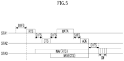
- FIG. 5 is a diagram for explaining a frame transmission operation based on CSMA/CA to which the present disclosure may be applied.
- the CSMA/CA mechanism includes virtual carrier sensing in addition to physical carrier sensing in which a STA directly senses a medium.
- Virtual carrier sensing is intended to compensate for problems that may occur in medium access, such as a hidden node problem.
- the MAC of the STA may use a Network Allocation Vector (NAV).
- NAV Network Allocation Vector
- the NAV is a value indicating, to other STAs, the remaining time until the medium is available for use by an STA currently using or having the right to use the medium. Therefore, the value set as NAV corresponds to a period in which the medium is scheduled to be used by the STA transmitting the frame, and the STA receiving the NAV value is prohibited from accessing the medium during the corresponding period.
- the NAV may be configured based on the value of the "duration" field of the MAC header of the frame.
- a STA1 intends to transmit data to a STA2, and a STA3 is in a position capable of overhearing some or all of frames transmitted and received between the STA1 and the STA2.
- a mechanism using RTS/CTS frames may be applied.
- the medium is in an idle state. That is, the STA1 may correspond to a hidden node to the STA3.
- it may be determined that the carrier sensing result medium of the STA3 is in an idle state while transmission of the STA2 is being performed. That is, the STA2 may correspond to a hidden node to the STA3.
- a STA outside the transmission range of one of the STA1 or the STA2, or a STA outside the carrier sensing range for transmission from the STA1 or the STA3 may not attempt to occupy the channel during data transmission and reception between the STA1 and the STA2.
- the STA1 may determine whether a channel is being used through carrier sensing. In terms of physical carrier sensing, the STA1 may determine a channel occupation idle state based on an energy level or signal correlation detected in a channel. In addition, in terms of virtual carrier sensing, the STA1 may determine a channel occupancy state using a network allocation vector (NAV) timer.
- NAV network allocation vector
- the STA1 may transmit an RTS frame to the STA2 after performing a backoff when the channel is in an idle state during DIFS.
- the STA2 may transmit a CTS frame as a response to the RTS frame to the STA1 after SIFS.
- the STA3 may set a NAV timer for a frame transmission period (e.g., SIFS + CTS frame + SIFS + data frame + SIFS + ACK frame) that is continuously transmitted thereafter, using the duration information included in the RTS frame.
- a NAV timer for a frame transmission period (e.g., SIFS + data frame + SIFS + ACK frame) that is continuously transmitted thereafter, using the duration information included in the CTS frame.
- the STA3 may set the NAV accordingly.
- the STA3 may update the NAV timer using duration information included in the new frame. The STA3 does not attempt channel access until the NAV timer expires.
- the STA1 may transmit the data frame to the STA2 after SIFS from the time point when the reception of the CTS frame is completed.
- the STA2 may transmit an ACK frame as a response to the data frame to the STA1 after SIFS.
- the STA3 may determine whether the channel is being used through carrier sensing when the NAV timer expires. When the STA3 determines that the channel is not used by other terminals during DIFS after expiration of the NAV timer, the STA3 may attempt channel access after a contention window (CW) according to a random backoff has passed.
- CW contention window
- FIG. 6 is a diagram for explaining an example of a frame structure used in a WLAN system to which the present disclosure may be applied.
- the PHY layer may prepare a MAC PDU (MPDU) to be transmitted. For example, when a command requesting transmission start of the PHY layer is received from the MAC layer, the PHY layer switches to the transmission mode and configures information (e.g., data) provided from the MAC layer in the form of a frame and transmits it. In addition, when the PHY layer detects a valid preamble of the received frame, the PHY layer monitors the header of the preamble and sends a command notifying the start of reception of the PHY layer to the MAC layer.
- MPDU MAC PDU
- a PHY layer protocol data unit (PPDU) frame format is defined.
- a basic PPDU frame may include a Short Training Field (STF), a Long Training Field (LTF), a SIGNAL (SIG) field, and a Data field.
- STF Short Training Field
- LTF Long Training Field
- SIG SIGNAL
- Data field e.g., Data field
- the most basic (e.g., non-High Throughput (HT)) PPDU frame format may consist of only L-STF (Legacy-STF), L-LTF (Legacy-LTF), SIG field, and data field.
- PPDU frame format e.g., HT-mixed format PPDU, HT-greenfield format PPDU, VHT (Very High Throughput) PPDU, etc.
- STF, LTF, and SIG fields may be included between the SIG field and the data field (this will be described later with reference to FIG. 7 ).
- the STF is a signal for signal detection, automatic gain control (AGC), diversity selection, precise time synchronization, and the like
- the LTF is a signal for channel estimation and frequency error estimation.
- the STF and LTF may be referred to as signals for synchronization and channel estimation of the OFDM physical layer.
- the SIG field may include a RATE field and a LENGTH field.
- the RATE field may include information on modulation and coding rates of data.
- the LENGTH field may include information on the length of data. Additionally, the SIG field may include a parity bit, a SIG TAIL bit, and the like.
- the data field may include a SERVICE field, a physical layer service data unit (PSDU), and a PPDU TAIL bit, and may also include padding bits if necessary.
- Some bits of the SERVICE field may be used for synchronization of the descrambler at the receiving end.
- the PSDU corresponds to the MAC PDU defined in the MAC layer, and may include data generated/used in the upper layer.
- the PPDU TAIL bit may be used to return the encoder to a 0 state.
- Padding bits may be used to adjust the length of a data field in a predetermined unit.
- a MAC PDU is defined according to various MAC frame formats, and a basic MAC frame consists of a MAC header, a frame body, and a Frame Check Sequence (FCS).
- the MAC frame may consist of MAC PDUs and be transmitted/received through the PSDU of the data part of the PPDU frame format.
- the MAC header includes a Frame Control field, a Duration/ID field, an Address field, and the like.
- the frame control field may include control information required for frame transmission/reception.
- the duration/ID field may be set to a time for transmitting a corresponding frame or the like.
- a null-data packet (NDP) frame format means a frame format that does not include a data packet. That is, the NDP frame refers to a frame format that includes a physical layer convergence procedure (PLCP) header part (i.e., STF, LTF, and SIG fields) in a general PPDU frame format and does not include the remaining parts (i.e., data field).
- PLCP physical layer convergence procedure
- a NDP frame may also be referred to as a short frame format.
- FIG. 7 is a diagram illustrating examples of PPDUs defined in the IEEE 802.11 standard to which the present disclosure may be applied.
- the basic PPDU format (IEEE 802.11a/g) includes L-LTF, L-STF, L-SIG and Data fields.
- the basic PPDU format may also be referred to as a non-HT PPDU format.
- the HT PPDU format (IEEE 802.11n) additionally includes HT-SIG, HT-STF, and HT-LFT(s) fields to the basic PPDU format.
- the HT PPDU format shown in FIG. 7 may be referred to as an HT-mixed format.
- an HT-greenfield format PPDU may be defined, and this corresponds to a format consisting of HT-GF-STF, HT-LTF1, HT-SIG, one or more HT-LTF, and Data field, not including L-STF, L-LTF, and L-SIG (not shown).
- VHT PPDU format (IEEE 802.11ac) additionally includes VHT SIG-A, VHT-STF, VHT-LTF, and VHT-SIG-B fields to the basic PPDU format.
- HE PPDU format (IEEE 802.11ax) additionally includes Repeated L-SIG (RL-SIG), HE-SIG-A, HE-SIG-B, HE-STF, HE-LTF(s), Packet Extension (PE) field to the basic PPDU format.
- R-SIG Repeated L-SIG
- HE-SIG-A HE-SIG-B
- HE-STF HE-LTF(s)
- PE Packet Extension
- Some fields may be excluded or their length may vary according to detailed examples of the HE PPDU format.
- the HE-SIG-B field is included in the HE PPDU format for multi-user (MU), and the HE-SIG-B is not included in the HE PPDU format for single user (SU).
- SU single user
- the HE trigger-based (TB) PPDU format does not include the HE-SIG-B, and the length of the HE-STF field may vary to 8 us.
- the Extended Range (HE ER) SU PPDU format does not include the HE-SIG-B field, and the length of the HE-SIG-A field may vary to 16us.
- FIGs. 8 to 10 are diagrams for explaining examples of resource units of a WLAN system to which the present disclosure may be applied.
- the RU may include a plurality of subcarriers (or tones).
- the RU may be used when transmitting signals to multiple STAs based on the OFDMA scheme.
- the RU may be defined even when a signal is transmitted to one STA.
- the RU may be used for STF, LTF, data field of the PPDU, etc.
- RUs corresponding to different numbers of tones are used to construct some fields of 20 MHz, 40 MHz, or 80 MHz X-PPDUs (X is HE, EHT, etc.).
- X is HE, EHT, etc.
- resources may be allocated in RU units shown for the X-STF, X-LTF, and Data field.
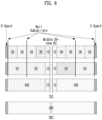
- FIG. 8 is a diagram illustrating an exemplary allocation of resource units (RUs) used on a 20 MHz band.
- 26-units i.e., units corresponding to 26 tones
- 6 tones may be used as a guard band in the leftmost band of the 20 MHz band
- 5 tones may be used as a guard band in the rightmost band of the 20 MHz band.
- 7 DC tones are inserted in the center band, that is, the DC band
- 26-units corresponding to each of the 13 tones may exist on the left and right sides of the DC band.
- 26-unit, 52-unit, and 106-unit may be allocated to other bands. Each unit may be allocated for STAs or users.
- the RU allocation of FIG. 8 is utilized not only in a situation for multiple users (MU) but also in a situation for a single user (SU), and in this case, it is possible to use one 242-unit as shown at the bottom of FIG. 8 . In this case, three DC tones may be inserted.
- RUs of various sizes that is, 26-RU, 52-RU, 106-RU, 242-RU, etc. are exemplified, but the specific size of these RUs may be reduced or expanded. Therefore, in the present disclosure, the specific size of each RU (i.e., the number of corresponding tones) is exemplary and not restrictive. In addition, within a predetermined bandwidth (e.g., 20, 40, 80, 160, 320 MHz, ...) in the present disclosure, the number of RUs may vary according to the size of the RU. In the examples of FIG. 9 and/or FIG. 10 to be described below, the fact that the size and/or number of RUs may be varied is the same as the example of FIG. 8 .
- FIG. 9 is a diagram illustrating an exemplary allocation of resource units (RUs) used on a 40 MHz band.
- 26-RU, 52-RU, 106-RU, 242-RU, 484-RU, and the like may be used in the example of FIG. 9 as well.
- 5 DC tones may be inserted at the center frequency
- 12 tones may be used as a guard band in the leftmost band of the 40MHz band
- 11 tones may be used as a guard band in the rightmost band of the 40MHz band.
- a 484-RU when used for a single user, a 484-RU may be used.
- FIG. 10 is a diagram illustrating an exemplary allocation of resource units (RUs) used on an 80 MHz band.
- 26-RU, 52-RU, 106-RU, 242-RU, 484-RU, 996-RU and the like may be used in the example of FIG. 10 as well.
- RU allocation of HE PPDUs and EHT PPDUs may be different, and the example of FIG. 10 shows an example of RU allocation for 80 MHz EHT PPDUs.
- HE PPDU 10 is the same in HE PPDU and EHT PPDU.
- EHT PPDU 23 DC tones are inserted into the DC band, and one 26-RU exists on the left and right sides of the DC band.
- one null subcarrier exists between 242-RUs rather than the center band, there are five null subcarriers in the EHT PPDU.
- one 484-RU does not include null subcarriers, but in the EHT PPDU, one 484-RU includes 5 null subcarriers.
- 996-RU when used for a single user, 996-RU may be used, and in this case, 5 DC tones are inserted in common with HE PPDU and EHT PPDU.
- EHT PPDUs over 160 MHz may be configured with a plurality of 80 MHz subblocks in FIG. 10 .
- the RU allocation for each 80 MHz subblock may be the same as that of the 80 MHz EHT PPDU of FIG. 10 . If the 80 MHz subblock of the 160 MHz or 320 MHz EHT PPDU is not punctured and the entire 80 MHz subblock is used as part of RU or multiple RU (MRU), the 80 MHz subblock may use 996-RU of FIG. 10 .
- the MRU corresponds to a group of subcarriers (or tones) composed of a plurality of RUs, and the plurality of RUs constituting the MRU may be RUs having the same size or RUs having different sizes.
- a single MRU may be defined as 52+26-tone, 106+26-tone, 484+242-tone, 996+484-tone, 996+484+242-tone, 2X996+484-tone, 3X996-tone, or 3X996+484-tone.
- the plurality of RUs constituting one MRU may correspond to small size (e.g., 26, 52, or 106) RUs or large size (e.g., 242, 484, or 996) RUs. That is, one MRU including a small size RU and a large size RU may not be configured/defined. In addition, a plurality of RUs constituting one MRU may or may not be consecutive in the frequency domain.
- the 80 MHz subblock may use RU allocation other than the 996-tone RU.
- the RU of the present disclosure may be used for uplink (UL) and/or downlink (DL) communication.
- the STA transmitting the trigger e.g., AP
- trigger information e.g., trigger frame or triggered response scheduling (TRS)
- the first STA may transmit a first trigger-based (TB) PPDU based on the first RU
- the second STA may transmit a second TB PPDU based on the second RU.
- the first/second TB PPDUs may be transmitted to the AP in the same time period.
- the STA transmitting the DL MU PPDU may allocate a first RU (e.g., 26/52/106/242-RU, etc.) to a first STA and allocate a second RU (e.g., 26/52/106/242-RU, etc.) to a second STA. That is, the transmitting STA (e.g., AP) may transmit HE-STF, HE-LTF, and Data field for the first STA through the first RU and transmit HE-STF, HE-LTF, and Data field for the second STA through the second RU, in one MU PPDU,
- a first RU e.g., 26/52/106/242-RU, etc.
- a second RU e.g., 26/52/106/242-RU, etc.
- Information on the allocation of RUs may be signaled through HE-SIG-B in the HE PPDU format.
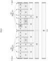
- FIG. 11 illustrates an example structure of a HE-SIG-B field.
- the HE-SIG-B field may include a common field and a user-specific field. If HE-SIG-B compression is applied (e.g., full-bandwidth MU-MIMO transmission), the common field may not be included in HE-SIG-B, and the HE-SIG-B content channel may include only a user-specific field. If HE-SIG-B compression is not applied, the common field may be included in HE-SIG-B.
- the common field may include information on RU allocation (e.g., RU assignment, RUs allocated for MU-MIMO, the number of MU-MIMO users (STAs), etc.)
- RU allocation e.g., RU assignment, RUs allocated for MU-MIMO, the number of MU-MIMO users (STAs), etc.
- the common field may include N*8 RU allocation subfields.
- One 8-bit RU allocation subfield may indicate the size (26, 52, 106, etc.) and frequency location (or RU index) of RUs included in the 20 MHz band.
- a value of the 8-bit RU allocation subfield is 00000000, it may indicate that nine 26-RUs are sequentially allocated in order from the leftmost to the rightmost in the example of FIG. 8 , if the value is 00000001, it may indicate that seven 26-RUs and one 52-RU are sequentially allocated in order from leftmost to rightest, and if the value is 00000010, it may indicate that five 26-RUs, one 52-RU, and two 26-RUs are sequentially allocated from the leftmost side to the rightmost side.
- the value of the 8-bit RU allocation subfield is 01000y2y1y0, it may indicate that one 106-RU and five 26-RUs are sequentially allocated from the leftmost to the rightmost in the example of FIG. 8 .
- multiple users/STAs may be allocated to the 106-RU in the MU-MIMO scheme.
- up to 8 users/STAs may be allocated to the 106-RU, and the number of users/STAs allocated to the 106-RU is determined based on 3-bit information (i.e., y2y1y0). For example, when the 3-bit information (y2y1y0) corresponds to a decimal value N, the number of users/STAs allocated to the 106-RU may be N+1.
- one user/STA may be allocated to each of a plurality of RUs, and different users/STAs may be allocated to different RUs.
- a predetermined size e.g., 106, 242, 484, 996-tones, (7)
- a plurality of users/STAs may be allocated to one RU, and MU-MIMO scheme may be applied for the plurality of users/STAs.
- the set of user-specific fields includes information on how all users (STAs) of the corresponding PPDU decode their payloads.
- User-specific fields may contain zero or more user block fields.
- the non-final user block field includes two user fields (i.e., information to be used for decoding in two STAs).
- the final user block field contains one or two user fields.
- the number of user fields may be indicated by the RU allocation subfield of HE-SIG-B, the number of symbols of HE-SIG-B, or the MU-MIMO user field of HE-SIG-A.
- a User-specific field may be encoded separately from or independently of a common field.
- FIG. 12 is a diagram for explaining a MU-MIMO method in which a plurality of users/STAs are allocated to one RU.
- the user-specific field of HE-SIG-B may include 8 user fields (i.e., 4 user block fields). Eight user fields may be assigned to RUs as shown in FIG. 12 .
- the user field may be constructed based on two formats.
- the user field for a MU-MIMO allocation may be constructed with a first format
- the user field for non-MU-MIMO allocation may be constructed with a second format.
- user fields 1 to 3 may be based on the first format
- user fields 4 to 8 may be based on the second format.
- the first format and the second format may contain bit information of the same length (e.g., 21 bits).
- the user field of the first format (i.e., format for MU-MIMO allocation) may be constructed as follows. For example, out of all 21 bits of one user field, B0-B10 includes the user's identification information (e.g., STA-ID, AID, partial AID, etc.), B 1 1-14 includes spatial configuration information such as the number of spatial streams for the corresponding user, B15-B18 includes Modulation and Coding Scheme (MCS) information applied to the Data field of the corresponding PPDU, B19 is defined as a reserved field, and B20 may include information on a coding type (e.g., binary convolutional coding (BCC) or low-density parity check (LDPC)) applied to the Data field of the corresponding PPDU.
- BCC binary convolutional coding
- LDPC low-density parity check
- the user field of the second format (i.e., the format for non-MU-MIMO allocation) may be constructed as follows. For example, out of all 21 bits of one user field, B0-B10 includes the user's identification information (e.g., STA-ID, AID, partial AID, etc.), B11-13 includes information on the number of spatial streams (NSTS) applied to the corresponding RU, B14 includes information indicating whether beamforming is performed (or whether a beamforming steering matrix is applied), B15-B18 includes Modulation and Coding Scheme (MCS) information applied to the Data field of the corresponding PPDU, B19 includes information indicating whether DCM (dual carrier modulation) is applied, and B20 may include information on a coding type (e.g., BCC or LDPC) applied to the Data field of the corresponding PPDU.
- B1-13 includes information on the number of spatial streams (NSTS) applied to the corresponding RU
- B14 includes information indicating whether beamforming is performed (or whether a beamforming steering matrix
- MCS MCS information
- MCS index MCS field, and the like used in the present disclosure may be indicated by a specific index value.
- MCS information may be indicated as index 0 to index 11.
- MCS information includes information on constellation modulation type (e.g., BPSK, QPSK, 16-QAM, 64-QAM, 256-QAM, 1024-QAM, etc.), and coding rate (e.g., 1/2, 2/ 3, 3/4, 5/6, etc.).
- coding rate e.g., 1/2, 2/ 3, 3/4, 5/6, etc.
- Information on a channel coding type e.g., BCC or LDPC
- BCC channel coding type
- FIG. 13 illustrates an example of a PPDU format to which the present disclosure may be applied.
- the PPDU of FIG. 13 may be referred as various names such as an EHT PPDU, a transmitted PPDU, a received PPDU, a first type or an Nth type PPDU.
- the PPDU or EHT PPDU of the present disclosure may be referred as various names such as a transmission PPDU, a reception PPDU, a first type or an Nth type PPDU.
- the EHT PPU may be used in an EHT system and/or a new wireless LAN system in which the EHT system is improved.
- the EHT MU PPDU of FIG. 13 corresponds to a PPDU carrying one or more data (or PSDUs) for one or more users. That is, the EHT MU PPDU may be used for both SU transmission and MU transmission.
- the EHT MU PPDU may correspond to a PPDU for one receiving STA or a plurality of receiving STAs.
- the EHT-SIG is omitted compared to the EHT MU PPDU.
- the STA may perform UL transmission based on the EHT TB PPDU format.
- L-STF to EHT-LTF correspond to a preamble or a physical preamble, and may be generated/transmitted/received/acquired/decoded in the physical layer .
- a Subcarrier frequency spacing of L-STF, L-LTF, L-SIG, RL-SIG, Universal SIGNAL (U-SIG), EHT-SIG field (these are referred to as pre-EHT modulated fields) may be set to 312.5 kHz.
- a subcarrier frequency spacing of the EHT-STF, EHT-LTF, Data, and PE field (these are referred to as EHT modulated fields) may be set to 78.125 kHz.
- the tone/subcarrier index of L-STF, L-LTF, L-SIG, RL-SIG, U-SIG, and EHT-SIG field may be indicated in units of 312.5 kHz
- the tone/subcarrier index of EHT-STF, EHT-LTF, Data, and PE field may be indicated in units of 78.125 kHz.
- the L-LTF and L-STF of FIG. 13 may be constructed identically to the corresponding fields of the PPDU described in FIGS. 6 to 7 .
- the L-SIG field of FIG. 13 may be constructed with 24 bits and may be used to communicate rate and length information.
- the L-SIG field includes a 4-bit Rate field, a 1-bit Reserved bit, a 12-bit Length field, a 1-bit Parity field, and a 6-bit Tail field may be included.
- the 12-bit Length field may include information on a time duration or a length of the PPDU.
- a value of the 12-bit Length field may be determined based on the type of PPDU. For example, for a non-HT, HT, VHT, or EHT PPDU, the value of the Length field may be determined as a multiple of 3. For example, for the HE PPDU, the value of the Length field may be determined as a multiple of 3 + 1 or a multiple of 3 + 2.
- the transmitting STA may apply BCC encoding based on a coding rate of 1/2 to 24-bit information of the L-SIG field. Thereafter, the transmitting STA may obtain 48-bit BCC coded bits. BPSK modulation may be applied to 48-bit coded bits to generate 48 BPSK symbols. The transmitting STA may map 48 BPSK symbols to any location except for a pilot subcarrier (e,g,, ⁇ subcarrier index -21, -7, +7, +21 ⁇ ) and a DC subcarrier (e.g., f subcarrier index 0 ⁇ ).
- a pilot subcarrier e,g, ⁇ subcarrier index -21, -7, +7, +21 ⁇
- DC subcarrier e.g., f subcarrier index 0 ⁇
- 48 BPSK symbols may be mapped to subcarrier indices-26 to -22, -20 to -8, -6 to -1, +1 to +6, +8 to +20, and +22 to +26.
- the transmitting STA may additionally map the signals of ⁇ -1, -1, -1, 1 ⁇ to the subcarrier index ⁇ -28, -27, +27, +28 ⁇ .
- the above signal may be used for channel estimation in the frequency domain corresponding to ⁇ -28, -27, +27, +28 ⁇ .
- the transmitting STA may construct RL-SIG which is constructed identically to L-SIG.
- RL-SIG BPSK modulation is applied.
- the receiving STA may recognize that the received PPDU is a HE PPDU or an EHT PPDU based on the existence of the RL-SIG.
- U-SIG Universal SIG
- the U-SIG may be referred as various names such as a first SIG field, a first SIG, a first type SIG, a control signal, a control signal field, and a first (type) control signal, etc.
- the U-SIG may include N-bit information and may include information for identifying the type of EHT PPDU.
- U-SIG may be configured based on two symbols (e.g., two consecutive OFDM symbols).
- Each symbol (e.g., OFDM symbol) for the U-SIG may have a duration of 4us, and the U-SIG may have a total 8us duration.
- Each symbol of the U-SIG may be used to transmit 26 bit information.
- each symbol of the U-SIG may be transmitted and received based on 52 data tones and 4 pilot tones.
- a bit information (e.g., 52 un-coded bits) may be transmitted
- the first symbol of the U-SIG (e.g., U-SIG-1) may transmit the first X bit information (e.g., 26 un-coded bits) of the total A bit information
- the second symbol of the U-SIG (e.g., U-SIG-2) may transmit the remaining Y-bit information (e.g., 26 un-coded bits) of the total A-bit information.
- the transmitting STA may obtain 26 un-coded bits included in each U-SIG symbol.
- the transmitting STA may generate 52 BPSK symbols allocated to each U-SIG symbol by performing BPSK modulation on the interleaved 52-coded bits.
- One U-SIG symbol may be transmitted based on 56 tones (subcarriers) from subcarrier index -28 to subcarrier index +28, except for DC index 0.
- the 52 BPSK symbols generated by the transmitting STA may be transmitted based on the remaining tones (subcarriers) excluding pilot tones -21, -7, +7, and +21 tones.
- the A bit information (e.g., 52 un-coded bits) transmitted by the U-SIG includes a CRC field (e.g., a 4-bit field) and a tail field (e.g., 6 bit-length field).
- the CRC field and the tail field may be transmitted through the second symbol of the U-SIG.
- the CRC field may be constructed based on 26 bits allocated to the first symbol of U-SIG and 16 bits remaining except for the CRC/tail field in the second symbol, and may be constructed based on a conventional CRC calculation algorithm.
- the tail field may be used to terminate the trellis of the convolution decoder, and for example, the tail field may be set to 0.
- a bit information (e.g., 52 un-coded bits) transmitted by the U-SIG (or U-SIG field) may be devided into version-independent bits and version-independent bits.
- a size of the version-independent bits may be fixed or variable.
- the version-independent bits may be allocated only to the first symbol of U-SIG, or the version-independent bits may be allocated to both the first symbol and the second symbol of U-SIG.
- the version-independent bits and the version-dependent bits may be referred as various names such as a first control bit and a second control bit, etc.
- the version-independent bits of the U-SIG may include a 3-bit physical layer version identifier (PHY version identifier).
- the 3-bit PHY version identifier may include information related to the PHY version of the transmitted/received PPDU.
- the first value of the 3-bit PHY version identifier may indicate that the transmission/reception PPDU is an EHT PPDU.
- the transmitting STA may set the 3-bit PHY version identifier to a first value.
- the receiving STA may determine that the received PPDU is an EHT PPDU based on the PHY version identifier having the first value.
- the version-independent bits of U-SIG may include a 1-bit UL/DL flag field.
- a first value of the 1-bit UL/DL flag field is related to UL communication, and a second value of the UL/DL flag field is related to DL communication.
- the version-independent bits of the U-SIG may include information on the length of a transmission opportunity (TXOP) and information on a BSS color ID.
- TXOP transmission opportunity
- EHT PPDU related to SU mode e.g., EHT PPDU related to MU mode
- EHT PPDU related to TB mode e.g., EHT PPDU related to Extended Range transmission, etc.
- information on the type of EHT PPDU may be included in the version-dependent bits of the U-SIG.
- the U-SIG may include information on 1) a bandwidth field containing information on a bandwidth, 2) a field containing information on a MCS scheme applied to EHT-SIG, 3) an indication field containing information related to whether the DCM technique is applied to the EHT-SIG, 4) a field containing information on the number of symbols used for EHT-SIG, 5) a field containing information on whether EHT-SIG is constructed over all bands, 6) a field containing information on the type of EHT-LTF/STF, and 7) a field indicating the length of EHT-LTF and CP length.
- Preamble puncturing may be applied to the PPDU of FIG. 13 .
- Preamble puncturing may mean transmission of a PPDU for which no signal is present in one or more 20 MHz subchannels among the bandwidth of the PPDU.
- Preamble puncturing may be applied to a PPDU transmitted to one or more users.
- the resolution of preamble puncturing may be 20 MHz for EHT MU PPDUs in OFDMA transmissions with bandwidths greater than 40 MHz and non-OFDMA transmissions with 80 MHz and 160 MHz bandwidths. That is, in the above case, puncturing on a subchannel smaller than 242-tone RU may not be allowed.
- the resolution of preamble puncturing may be 40 MHz. That is, puncturing for a subchannel smaller than 484-tone RU in a 320 MHz bandwidth may not be allowed. In addition, preamble puncturing may not be applied to the primary 20 MHz channel in the EHT MU PPDU.
- information on preamble puncturing may be included in the U-SIG and/or the EHT-SIG.
- the first field of the U-SIG may include information on the contiguous bandwidth of the PPDU
- the second field of the U-SIG may include information on preamble puncturing applied to the PPDU.
- the U-SIG and the EHT-SIG may include information on preamble puncturing based on the following method. If the bandwidth of the PPDU exceeds 80 MHz, the U-SIG may be individually constructed in units of 80 MHz. For example, if the bandwidth of the PPDU is 160 MHz, the PPDU may include a first U-SIG for a first 80 MHz band and a second U-SIG for a second 80 MHz band. In this case, the first field of the first U-SIG includes information on the 160 MHz bandwidth, and the second field of the first U-SIG includes information on preamble puncturing applied to the first 80 MHz band (i.e., information on a preamble puncturing pattern).
- the first field of the second U-SIG includes information on a 160 MHz bandwidth
- the second field of the second U-SIG includes information on preamble puncturing applied to a second 80 MHz band (i.e., information on a preamble puncturing pattern).
- the EHT-SIG following the first U-SIG may include information on preamble puncturing applied to the second 80 MHz band (i.e., information on a preamble puncturing pattern)
- the EHT-SIG following the second U-SIG may include information on preamble puncturing applied to the first 80 MHz band (i.e., information on a preamble puncturing pattern).
- the U-SIG and the EHT-SIG may include information on preamble puncturing based on the following method.
- the U-SIG may include information on preamble puncturing for all bands (i.e., information on a preamble puncturing pattern). That is, EHT-SIG does not include information on preamble puncturing, and only U-SIG may include information on preamble puncturing (ie, information on a preamble puncturing pattern).
- U-SIG may be constructed in units of 20 MHz. For example, if an 80 MHz PPDU is constructed, the U-SIG may be duplicated. That is, the same 4 U-SIGs may be included in the 80 MHz PPDU. PPDUs exceeding 80 MHz bandwidth may include different U-SIGs.
- the EHT-SIG of FIG. 13 may include control information for the receiving STA.
- EHT-SIG may be transmitted through at least one symbol, and one symbol may have a length of 4us.
- Information on the number of symbols used for EHT-SIG may be included in U-SIG.
- the EHT-SIG may include technical features of HE-SIG-B described through FIGS. 11 and 12 .
- EHT-SIG like the example of FIG. 8 , may include a common field and a user-specific field.
- the Common field of the EHT-SIG may be omitted, and the number of user-specific fields may be determined based on the number of users.
- the common field of the EHT-SIG and the user-specific field of the EHT-SIG may be coded separately.
- One user block field included in the user-specific field may contain information for two user fields, but the last user block field included in the user-specific field may contain one or two user fields. That is, one user block field of the EHT-SIG may contain up to two user fields.
- each user field may be related to MU-MIMO allocation or non-MU-MIMO allocation.
- the common field of the EHT-SIG may include a CRC bit and a Tail bit
- the length of the CRC bit may be determined as 4 bits
- the length of the tail bit is determined by 6 bits and may be set to 000000.
- the common field of the EHT-SIG may include RU allocation information.
- RU allocation information may mean information on the location of an RU to which a plurality of users (i.e., a plurality of receiving STAs) are allocated.
- RU allocation information may be configured in units of 9 bits (or N bits).
- a mode in which a common field of EHT-SIG is omitted may be supported.
- the mode in which the common field of the EHT-SIG is omitted may be referred as a compressed mode.
- a plurality of users (i.e., a plurality of receiving STAs) of the EHT PPDU may decode the PPDU (e.g., the data field of the PPDU) based on non-OFDMA. That is, a plurality of users of the EHT PPDU may decode a PPDU (e.g., a data field of the PPDU) received through the same frequency band.
- multiple users of the EHT PPDU may decode the PPDU (e.g., the data field of the PPDU) based on OFDMA. That is, a plurality of users of the EHT PPDU may receive the PPDU (e.g., the data field of the PPDU) through different frequency bands.
- EHT-SIG may be constructed based on various MCS scheme. As described above, information related to the MCS scheme applied to the EHT-SIG may be included in the U-SIG.
- the EHT-SIG may be constructed based on the DCM scheme.
- the DCM scheme may reuse the same signal on two subcarriers to provide an effect similar to frequency diversity, reduce interference, and improve coverage. For example, modulation symbols to which the same modulation scheme is applied may be repeatedly mapped on available tones/subcarriers.
- modulation symbols e.g., BPSK modulation symbols
- first contiguous half tones e.g., 1st to 26th tones
- modulation symbols e.g., BPSK modulation symbols
- the remaining contiguous half tones e.g., 27th to 52nd tones. That is, a modulation symbol mapped to the 1st tone and a modulation symbol mapped to the 27th tone are the same.
- the EHT-STF of FIG. 13 may be used to enhance automatic gain control (AGC) estimation in a MIMO environment or an OFDMA environment.
- the EHT-LTF of FIG. 13 may be used to estimate a channel in a MIMO environment or an OFDMA environment.
- Information on the type of STF and/or LTF may be included in the U-SIG field and/or the EHT-SIG field of FIG. 13 .
- GI guard interval
- the PPDU (i.e., EHT PPDU) of FIG. 13 may be constructed based on an example of RU allocation of FIGS. 8 to 10 .
- a EHT PPDU transmitted on a 20 MHz band may be constructed based on the RU of FIG. 8 . That is, a RU location of EHT-STF, EHT-LTF, and data field included in the EHT PPDU may be determined as shown in FIG. 8 .
- a EHT PPDU transmitted on a 40 MHz band that is, a 40 MHz EHT PPDU may be constructed based on the RU of FIG. 9 . That is, a RU location of EHT-STF, EHT-LTF, and data field included in the EHT PPDU may be determined as shown in FIG. 9 .
- the EHT PPDU transmitted on the 80 MHz band may be constructed based on the RU of FIG. 10 . That is, a RU location of EHT-STF, EHT-LTF, and data field included in the EHT PPDU may be determined as shown in FIG. 10 .
- the tone-plan for 80 MHz in FIG. 10 may correspond to two repetitions of the tone-plan for 40 MHz in FIG. 9 .
- the tone-plan for 160/240/320 MHz may be configured in the form of repeating the pattern of FIG. 9 or 10 several times.
- the PPDU of FIG. 13 may be identified as an EHT PPDU based on the following method.
- the receiving STA may determine the type of the received PPDU as the EHT PPDU based on the following. For example, when 1) the first symbol after the L-LTF signal of the received PPDU is BPSK, 2) RL-SIG in which the L-SIG of the received PPDU is repeated is detected, and 3) the result of applying the modulo 3 calculation to the value of the Length field of the L-SIG of the received PPDU (i.e., the remainder after dividing by 3) is detected as 0, the received PPDU may be determined as a EHT PPDU.
- the receiving STA may determine the type of the EHT PPDU based on bit information included in symbols subsequent to the RL-SIG of FIG. 13 . In other words, the receiving STA may determine the received PPDU as a EHT PPDU, based on 1) the first symbol after the L-LTF signal, which is BSPK, 2) RL-SIG contiguous to the L-SIG field and identical to the L-SIG, and 3) L-SIG including a Length field in which the result of applying modulo 3 is set to 0.
- the receiving STA may determine the type of the received PPDU as the HE PPDU based on the following. For example, when 1) the first symbol after the L-LTF signal is BPSK, 2) RL-SIG in which L-SIG is repeated is detected, and 3) the result of applying modulo 3 to the length value of L-SIG is detected as 1 or 2, the received PPDU may be determined as a HE PPDU.
- the receiving STA may determine the type of the received PPDU as non-HT, HT, and VHT PPDU based on the following. For example, when 1) the first symbol after the L-LTF signal is BPSK and 2) RL-SIG in which L-SIG is repeated is not detected, the received PPDU may be determined as non-HT, HT, and VHT PPDU.
- the receiving STA when the receiving STA detects an RL-SIG in which the L-SIG is repeated in the received PPDU, it may be determined that the received PPDU is a HE PPDU or an EHT PPDU. In this case, if the rate (6Mbps) check fails, the received PPDU may be determined as a non-HT, HT, or VHT PPDU. If the rate (6Mbps) check and parity check pass, when the result of applying modulo 3 to the Length value of L-SIG is detected as 0, the received PPDU may be determined as an EHT PPDU, and when the result of Length mod 3 is not 0, it may be determined as a HE PPDU.
- the PPDU of FIG. 13 may be used to transmit and receive various types of frames.
- the PPDU of FIG. 13 may be used for (simultaneous) transmission and reception of one or more of a control frame, a management frame, or a data frame.
- the U-SIG content is the same in both 20 MHz subchannels.
- the U-SIG content is the same in all non-punctured 20 MHz subchannels.
- the U-SIG content is the same on all non-punctured 20 MHz subchannels within each 80 MHz subblock and may be different from the U-SIG content in other 80 MHz subblocks.
- the U-SIG-1 part of the U-SIG of the EHT MU PPDU may include PHY version identifier (B0-B2), BW (B3-B5), UL/DL (B6), BSS color (B7-B12), and TXOP (B13-B19), and U-SIG-2 part may include PPDU type and compression mode (B0-B1), validate (B2), punctured channel information (B3-B7), validate (B8), EHT-SIG MCS (B9-B10), number of EHT-SIG symbols (B11-B15), CRC (B16-B19), and tail (B20-B25).
- 1 denotes a non-punctured subchannel
- x denotes a punctured subchannel.
- the puncturing granularity for the 80 MHz and 160 MHz PPDU bandwidths may be 20 MHz
- the puncturing granularity for the 320 MHz PPDU bandwidth may be 40 MHz.
- the U-SIG-1 part of the U-SIG of the EHT TB PPDU may include a version identifier (B0-B2), BW (B3-B5), UL/DL (B6), BSS color (B7-B12), TXOP (B13-B19), and disregard (B20-B25), and U-SIG-2 part may include PPDU type and compression mode (B0-B1), validate (B2), spatial reuse 1 (B3-B6), spatial reuse 2 (B7-B10), disregard (B11-B15), CRC (B16-B19), and tail (B20-B25).
- the U-SIG field of the EHT MU PPDU includes 5-bit punctured channel information, but the EHT TB PPDU does not include punctured channel information. This is because it is assumed that the EHT TB PPDU is constructed according to resource allocation indicated by the trigger frame or TRS control information, so the STA does not need to inform the AP of the resource information of the EHT TB PPDU.
- the STA may not respond with the HE TB PPDU. For example, if, in the non-AP STA, a common information field included in the trigger frame or one or more subfields of an user field addressed to the non-AP STA or selected by the non-AP STA are not recognized, supported, or have an unsatisfied value, the corresponding non-AP STA may choose not to respond to the trigger frame.
- the corresponding non-AP STA may choose not to respond to the TRS control subfield.
- FIG. 14 is a diagram representing an illustrative format of a trigger frame to which the present disclosure may be applied.
- a trigger frame may allocate a resource for at least one TB PPDU transmission and request TB PPDU transmission.
- a trigger frame may also include other information required by a STA which transmits a TB PPDU in response thereto.
- a trigger frame may include common information and a user information list field in a frame body.
- a common information field may include information commonly applied to at least one TB PPDU transmission requested by a trigger frame, e.g., a trigger type, a UL length, whether a subsequent trigger frame exists (e.g., More TF), whether channel sensing (CS) is required, a UL bandwidth (BW), etc.
- FIG. 14 illustratively shows a EHT variant common information field format.
- a trigger type subfield in a 4-bit size may have a value from 0 to 15.
- a value of a trigger type subfield, 0, 1, 2, 3, 4, 5, 6 and 7, is defined as corresponding to basic, Beamforming Report Poll (BFRP), multi user-block acknowledgment request (MU-BAR), multi user-request to send (MU-RTS), Buffer Status Report Poll (BSRP), groupcast with retries (GCR) MU-BAR, Bandwidth Query Report Poll (BQRP) and NDP Feedback Report Poll (NFRP) and a value of 8-15 is defined as being reserved.
- BFRP Beamforming Report Poll
- MU-BAR multi user-block acknowledgment request
- MU-RTS multi user-request to send
- BSRP Buffer Status Report Poll
- GCR groupcast with retries
- BQRP Bandwidth Query Report Poll
- NFRP NDP Feedback Report Poll
- a trigger dependent common information subfield may include information that is selectively included based on a trigger type.
- a special user information field may be included in a trigger frame.
- a special user information field does not include user-specific information, but includes extended common information which is not provided in a common information field.
- a user information list includes at least 0 user information field.
- FIG. 14 illustratively represents an EHT variant user information field format.
- a AID12 subfield is basically a user information field for a STA having a corresponding AID.
- a field when a field has a predetermined specific value, it may be utilized for other purpose including allocating a random access (RA)-RU or being configured in a form of a special user information field.
- a special user information field is a user information field which does not include user-specific information but includes extended common information not provided in a common information field.
- a special user information field may be identified by an AID12 value of 2007 and a special user information field flag subfield in a common information field may represent whether a special user information field is included.
- a RU allocation subfield may represent a size and a position of a RU/a MRU.
- a RU allocation subfield may be interpreted with a PS 160 (primary/secondary 160MHz) subfield of a user information field, a UL BW subfield of a common information field, etc.
- PS 160 primary/secondary 160MHz
- mapping of B7-B1 of a RU allocation subfield may be defined along with a setting of a B0 and PS160 subfield of a RU allocation subfield.
- Table 2 shows an example of encoding of a PS 160 subfield and a RU allocation subfield of a EHT variant user information field.
- B0 of a RU allocation subfield When B0 of a RU allocation subfield is set as 0, it may represent that RU/MRU allocation is applied to a primary 80MHz channel and when that value is set as 1, it may represent that RU allocation is applied to a secondary 80MHz channel of primary 160MHz. It may represent that when B0 of a RU allocation subfield is set as 0, RU/MRU allocation is applied to lower 80MHz of secondary 160MHz and when that value is set as 1, RU allocation is applied to upper 80MHz of secondary 160MHz.
- a value of PS160, B0, X0 and X1 may be set as 0.
- a value of PS160, B0, X0 and X1 may be set as in Table 3.
- This configuration represents absolute frequency order for primary and secondary 80MHz and 160MHz channels. Order from the left to the right represents order from a low frequency to a high frequency.
- a primary 80MHz channel is indicated as P80
- a secondary 80MHz channel is indicated as S80
- a secondary 160MHz channel is indicated as S160.
- MAP multi-access point
- a MAP operation may be defined as an operation between a master AP (or a sharing AP) and a slave AP (or a shared AP).
- a master AP plays a role of initiating and controlling a MAP operation for transmission or reception between multiple APs.
- a master AP groups a slave AP and manages a link with slave APs to share information between slave APs.
- a master AP manages information of a BSS configured with slave APs and information of STAs associated with a corresponding BSS.
- a slave AP may be associated with a master AP and share control information, management information and data traffic with each other.
- a slave AP performs a basic function of an AP which may establish a BSS in a wireless LAN in the same way.
- a STA in a MAP operation may be associated with a slave AP or a master AP to configure a BSS.
- a master AP and a slave AP may perform direct transmission or reception with each other.
- a master AP and a STA may not be able to perform direct transmission or reception with each other.
- a slave AP e.g., a slave AP associated with a STA
- a slave AP may perform direct transmission or reception with a STA.
- One of slave APs may become a master AP.
- a MAP operation is a technique in which at least one AP transmits and receives information to at least one STA.
- a C-TDMA coordinated-time division multiple access
- a C-OFDMA coordinated-orthogonal frequency division multiple access
- a C-SR coordinated-spatial reuse
- a coordinated beamforming (C-BF) or joint beamforming technique which performs simultaneous transmission or reception in cooperation may be also applied for a MAP operation.
- FIG. 15 is a diagram for describing various transmission or reception techniques in a MAP environment to which the present disclosure may be applied.
- STX single transmission
- AP1 and AP2 perform transmission to STA1 and STA2 at the same time in the same frequency bandwidth, a collision may occur on a wireless medium.
- performance may be improved through a method for reducing inter-symbol interference (ISI) through cooperation between neighboring APs or performing transmission together.
- ISI inter-symbol interference
- AP1 may perform transmission to STA1 in a first bandwidth and AP2 may perform transmission to STA2 in a second bandwidth at the same time, avoiding interference.
- FIG. 15(c) shows cooperative beamforming or nulling technique in which AP1 nulls interference to AP2 and/or STA2 while performing transmission to STA1 and AP2 nulls interference to AP1 and/or STA1 while performing transmission to STA2.
- FIG. 15(c) shows cooperative beamforming or nulling technique in which AP1 nulls interference to AP2 and/or STA2 while performing transmission to STA1 and AP2 nulls interference to AP1 and/or STA1 while performing transmission to STA2.
- FIG. 15(d) shows an AP selection method in which an AP with a good channel condition among the adjacent APs performs transmission.
- joint transmission (JTX) or joint reception (JRX) in which multiple APs cooperate to perform transmission or reception simultaneously may be applied, and further, joint MU-MIMO may be supported.
- Step 1 Distribute a resource region to each AP through a trigger frame from a master AP (i.e., an AP-to-AP trigger frame, or a master trigger frame)
- a master AP i.e., an AP-to-AP trigger frame, or a master trigger frame
- Step 2 Each AP performs DL (i.e., from an AP to a STA) data transmission in a resource region distributed to it, or transmits a trigger frame (i.e., an AP-to-STA trigger frame) for UL (i.e., from a STA to an AP) data transmission in a resource region distributed to it.
- DL i.e., from an AP to a STA
- UL i.e., from a STA to an AP
- Step 3 A STA transmits a response to DL data, or transmits through UL data (e.g., a TB PPDU).
- UL data e.g., a TB PPDU
- a resource distributed between APs When a resource distributed between APs is a frequency resource, it may correspond to a C-OFDMA method, when it is a time resource, it may correspond to a C-TDMA technique and when it is a spatial resource (or beam), it may correspond to a CBF method.
- a C-OFDMA technique i.e., a multi-AP operation through a resource distinguished in a frequency domain
- a scope of the present disclosure is not limited thereto, and may additionally or alternatively include a multi-AP operation through a resource distinguished in another domain (e.g., a time domain and/or a space domain).
- the minimum occupied channel width per AP In order to perform AP-to-AP cooperative transmission, particularly C-OFDMA-based transmission in a WLAN system, it is necessary to define the minimum occupied channel width per AP and a signaling method indicating it.
- the minimum occupied channel width per AP described below may be replaced with the minimum occupied time length per AP, the minimum number of occupied beams per AP, etc.
- a frequency resource allocated to one AP may have a size greater than or equal to the minimum occupied channel width.
- the minimum occupied channel width may be a preamble puncturing unit (e.g., 20MHz or 242-tone RU) or an U-SIG configuration unit (e.g., 80MHz or 996-tone RU).
- a preamble puncturing unit e.g., 20MHz or 242-tone RU
- an U-SIG configuration unit e.g., 80MHz or 996-tone RU
- a preamble puncturing unit may be 20MHz or 242-tone RU. If a preamble puncturing unit of a WLAN system is defined differently than 20MHz or 242-tone RU, the present disclosure includes defining a preamble puncturing unit other than 20MHz or 242-tone RU as the minimum occupied channel width.
- a preamble puncturing unit may refer to an inactive or unavailable resource unit.
- the disabled subchannel bitmap information of each AP may be exchanged between APs or may be provided from a slave AP to a master AP.
- a resource for C-OFDMA may be allocated by avoiding a disabled subchannel of these AP(s). For example, it may be assumed that in a 80MHz bandwidth (BW), a second 20MHz subchannel is disabled in AP1 and a third 20MHz subchannel is disabled in AP2.
- AP1 may be allocated a frequency resource including a third 20MHz subchannel and AP2 may be allocated a frequency resource including a second 20MHz subchannel. Accordingly, APs may be dividedly allocated a frequency resource and perform transmission or reception in a C-OFDMA manner.
- the minimum occupied channel width when defined as a 242-tone RU, it may be easier to avoid inter-frequency interference because there is a guard subcarrier or a null subcarrier that may use an adjacent subcarrier as a guard.
- a RU in a unit smaller than a 242-tone RU may be applied as the minimum occupied channel width.
- the minimum occupied channel width may be defined based on a size of a frequency unit less than or equal to a preamble puncturing unit.
- the minimum occupied channel width may be defined in a unit of a 106-tone RU, and a 26-tone RU between neighboring 106-tone RUs may be used as a guard band.
- an U-SIG configuration unit may be 80MHz or 996-tone RU.
- an U-SIG may be configured differently in a 80MHz unit.
- four U-SIGs transmitted within one 80MHz i.e., an U-SIG repeated every 20MHz
- the minimum occupied channel width per AP for C-OFDMA may be defined as 80MHz.
- multiple APs may perform transmission within one 80MHz band, and an U-SIG transmitted by each of multiple APs may be the same.
- one AP may transmit not only information about its own allocation channel, but also information about an allocation channel of at least another AP by including them in an U-SIG.
- an U-SIG is not transmitted in a subchannel corresponding to a preamble punctured within a 80MHz band, an U-SIG may be configured to include all channel allocation information of a plurality of APs allocated to a corresponding 80MHz band.
- each AP may be allocated to one 80MHz band in the present disclosure.
- the minimum occupied channel width per AP is defined as 80MHz
- one AP may transmit an U-SIG including its own channel allocation information in one 80MHz channel and another AP may transmit an U-SIG including its own channel allocation information in another 80MHz channel.
- each AP may configure and transmit an U-SIG by considering only itself within allocated 80MHz.
- channel/subchannel-related information may need to be reported/shared between APs.
- a master AP may collect/acquire channel/subchannel-related information from slave AP(s).
- a subchannel unit may be the same as the minimum occupied channel width described above, but the scope of the present disclosure is not limited thereto, and a partial frequency domain among the entire bandwidth may be referred to as a sub-channel.
- Channel/subchannel-related information may include channel/subchannel information, channel/subchannel state information, etc.
- channel/subchannel information may include available channel/subchannel information of an AP and/or a STA, unavailable (e.g., disabled, punctured, inactive) channel/subchannel information, a channel/subchannel type (e.g., a primary channel, a secondary channel), a channel/subchannel width, a frequency position, information about a subchannel within a channel, etc.
- Channel/subchannel state information may include occupancy state, channel load, a measurement result, etc. for channel(s)/subchannel(s) that may be identified by channel/subchannel information.
- channel/subchannel-related information for a MAP operation may include information about a channel/a subchannel between APs (e.g., between a master AP and a slave AP), and/or information about a channel/a subchannel between an AP and a STA (e.g., between a master AP and a STA associated with a master AP, between a slave AP and a STA associated with a slave AP).
- APs e.g., between a master AP and a slave AP
- STA e.g., between a master AP and a STA associated with a master AP, between a slave AP and a STA associated with a slave AP.
- channel/subchannel-related information for a MAP operation and a signaling method between APs and/or between an AP and a STA for requesting/responding/sharing it are described.
- channel allocation method for APs for APs based on such channel/subchannel-related information are described.
- FIG. 16 is a diagram for describing an example of a method performed in a first AP in a MAP operation according to the present disclosure.
- a first AP may transmit channel-related information to a second AP.
- Channel-related information may be transmitted in response to a request from a second AP (i.e., in a solicited manner), or without a request (i.e., in an unsolicited manner).
- Channel-related information may include related information about a channel and/or a subchannel. As described above, channel/subchannel-related information may include at least one of channel/subchannel information or channel/subchannel state information.
- channel/subchannel information may include information about an available channel/subchannel of a first AP or information about an unavailable channel/subchannel.
- information about an unavailable channel/subchannel may include a disabled channel/subchannel bitmap, punctured channel/subchannel information, inactive channel/subchannel information, etc.
- channel/subchannel state information may include state information about a channel/a subchannel for at least one of a BSS or an OBSS received/acquired from at least one STA associated with a first AP.
- state information may include at least one of a CCA state, a channel load, a receive power indicator (RPI), an average noise power indicator (ANPI), an idle power indicator (IPI), a receive channel power indicator (RCPI), or a receive signal to noise indicator (RSNI).
- state information may include occupancy state information, channel load information, frame measurement result information, etc. other than examples described above.
- a first AP may receive resource allocation information related to a MAP operation from a second AP.
- Resource allocation information may be determined by a second AP based on channel/subchannel-related information from at least one AP of an AP group including a first AP.
- Resource allocation information may be provided to each AP of an AP group in a dynamic/semi-static/static manner. For example, according to a dynamic manner, resource allocation information may be provided to a first AP by being included in a trigger frame (e.g., a master trigger frame provided from a second AP to a first AP) for a MAP operation of a first AP (e.g., performing frame exchange between at least one STA associated with a first AP).
- a trigger frame e.g., a master trigger frame provided from a second AP to a first AP
- a MAP operation of a first AP e.g., performing frame exchange between at least one STA associated with a first AP.
- resource allocation information instead of providing resource allocation information for each frame exchange, information on a candidate resource that a MAP operation of a first AP may be performed may be provided in advance as resource allocation information, and in a semi-static manner, resource allocation information may be updated and provided based on a predetermined period or event.
- a first AP may perform frame exchange with at least one STA associated with a first AP on a specific resource based on resource allocation information.
- a specific resource may be defined on a frequency domain.
- FIG. 17 is a diagram for describing an example of a method performed in a second AP in a MAP operation according to the present disclosure.
- a second AP may receive channel-related information of an AP group.
- an AP group may include a first AP, and may receive each channel-related information from each of all or part of APs of an AP group.
- a second AP may transmit resource allocation information for each of at least one AP of an AP group. For example, a second AP may determine resource allocation information of a corresponding AP for each of all or part of APs of an AP group and provide it to a corresponding AP.
- a method for transmitting or receiving channel-related information specific characteristics of channel/subchannel information and channel/subchannel state information that may be included in channel-related information, information on which resource allocation information is based, a method for transmitting or receiving resource allocation information, etc. are the same as those described in FIG. 16 , so an overlapping description is omitted.
- FIG. 18 is a diagram for describing an example of a method performed in a STA in a MAP operation according to the present disclosure.
- a STA may report channel state information to a first AP.
- Channel state information may correspond to, for example, channel/subchannel state information that may be acquired by a first AP from at least one STA associated with it in an example of FIG. 16 .
- a STA may report channel/subchannel state information by a request from a first AP or in an unsolicited manner. This channel/subchannel state information may be included in channel/subchannel-related information transmitted from a first AP to a second AP.
- channel/subchannel-related information transmitted from a first AP to a second AP may be determined based on channel/subchannel state information from a STA (along with channel/subchannel state information reported to a first AP from at least one another STA, if any).
- a STA may perform frame exchange with a first AP. For example, a specific resource where a STA and a first AP perform frame exchange may be based on resource allocation information determined by a second AP. Resource allocation information may be provided from a second AP to a first AP, and a STA may receive resource allocation information (or a (master) trigger frame including resource allocation information) from a second AP and acquire/decode resource allocation information.
- resource allocation information may be provided from a second AP to a first AP, and a STA may receive resource allocation information (or a (master) trigger frame including resource allocation information) from a second AP and acquire/decode resource allocation information.
- Frame exchange between a first AP and a STA may include downlink transmission from a first AP and/or uplink transmission based on a trigger frame from a first AP.
- a method for transmitting or receiving channel-related information specific characteristics of channel/subchannel information and channel/subchannel state information that may be included in channel-related information, information on which resource allocation information is based, a method for transmitting or receiving resource allocation information, etc. are the same as those described in FIG. 16 , so an overlapping description is omitted.
- channel-related information between a STA and an AP and/or between an AP and an AP may be exchanged/shared/reported.
- STA(s) may report channel state information of a BSS and OBSS AP to their BSS AP (e.g., slave AP).
- BSS AP e.g., slave AP
- Slave AP(s) may report their channel information and channel state information acquired from STA(s) to a master AP. Based on this channel-related information, a master AP may perform resource allocation/scheduling for a MAP operation.
- a master AP may operate like a master AP, so it may be seen that channel-related information is exchanged/shared between APs.
- a STA associated with an AP having a MAP capability may report channel state information about a BSS and/or an OBSS to a BSS AP associated with it.
- a MAP capability e.g., a C-OFDMA capability
- Channel state information from a STA may include channel state information for the entire channel width and/or channel state information in a unit of a subchannel.
- channel state information may include at least one information that may be included in a measurement-related element of an action frame.
- channel state information may include at least one of a CCA state (e.g., CCA busy/idle), a channel load, a receive power indicator (RPI), an average noise power indicator (ANPI), an idle power indicator (IPI), a receive channel power indicator (RCPI), or a receive signal to noise indicator (RSNI).
- CCA state e.g., CCA busy/idle
- RPI receive power indicator
- ANPI average noise power indicator
- IPI idle power indicator
- RCPI receive channel power indicator
- RSNI receive signal to noise indicator
- channel state information in a unit of a subchannel is not defined.
- a new report method for reporting channel state information in a unit of a subchannel is defined to support a MAP operation such as C-OFDMA.
- channel state information in a unit of a channel/a subchannel may be reported through at least one of a response to a control frame (e.g., a trigger frame), a response to a management frame (e.g., a measurement request, a neighbor report request, a reduced neighbor report request) (e.g., a measurement response, a neighbor report response, (a reduced neighbor report response)), or a response to a data frame (e.g., information included in an A-control field).
- a control frame e.g., a trigger frame
- a management frame e.g., a measurement request, a neighbor report request, a reduced neighbor report request
- a measurement response e.g., a measurement response, a neighbor report response, (a reduced neighbor report response)
- a data frame e.g., information included in an A-control field
- channel state information in a unit of a channel/a subchannel may be reported by a request from an AP (i.e., a solicited manner), or may be reported without a request from an AP (i.e., an unsolicited manner).
- a measurement option by subchannel may be additionally defined when a measurement type is CCA, a channel load or a frame request/response.
- a new measurement type may be defined to additionally define an element indicating CCA, channel load, frame measurement, etc. for each subchannel.
- a target beacon transmission time (TBTT) information length may be set as a value other than 16 and used for a MAP purpose.
- a new action frame for a MAP purpose may be defined to request or inform which channel/subchannel unit will be used for report and/or what type of channel state information is and receive feedback for a requested type of channel state information in a corresponding subchannel unit in response thereto.
- a new A-control field for a MAP purpose may be defined.
- an A(aggregated)-control field included in a HT control field of a MAC header may include at least one control subfield list, and each control subfield may include a control ID and control information.
- Control information corresponding to a new/existing control ID may include channel state information in a unit of a channel/a subchannel.
- a method for separately requesting/informing a subchannel with a good channel state e.g., a subchannel corresponding to a bit position of 1 in a bitmap
- a subchannel with a bad channel state e.g., a subchannel corresponding to a bit position of 0 in a bitmap
- a subchannel indicated in a bitmap e.g., indicated as 1 or indicated as 0
- the number of subchannels reported may correspond to the number of bit positions indicated as 1 (or indicated as 0) in a bitmap.
- a master AP may request slave AP(s) participating in a MAP operation to report their respective channel-related information, and each slave AP may report its respective channel-related information. Alternatively, each slave AP may report its respective channel-related information in an unsolicited manner.
- Channel-related information may include channel/subchannel information of each slave AP, or channel/subchannel state information reported from STA(s) associated with each slave AP.
- Channel/subchannel information among the channel-related information may include information included in an existing beacon or neighbor report such as a capability of each AP, a disabled subchannel bitmap field included in an EHT operation element, inactive subchannel (inactive_subchannels) information corresponding to a TXVECTOR parameter, etc.
- Channel/subchannel state information among the channel-related information may include channel state information for BSS and OBSS APs measured by STA(s) of an AP, etc.
- channel-related information may include information about STA(s) associated with each AP (or belonging to an AP).
- Information about a STA may include STA identification information, a MAC address, a capability, etc.
- Channel-related information may be reported in a form of a control frame (e.g., a response to a trigger frame from a master AP), or may be reported in a form of a management frame (e.g., a measurement request/response).
- a control frame e.g., a response to a trigger frame from a master AP
- a management frame e.g., a measurement request/response
- a trigger frame that a master AP requests channel-related information to slave AP(s) may be defined.
- This trigger frame may be referred to as a MAP trigger frame, and may be defined in a format separate from a master trigger frame including resource allocation information for a MAP operation or in a format that may be applied to both a MAP trigger frame and a master trigger frame.
- a receiver address (RA) of a MAP trigger frame may include an address of each slave AP, or may be set as a broadcast address.
- a master AP may transmit a probe request including a newly defined MAP element to a slave AP.
- a slave AP may report a probe response including a newly defined MAP element to a master AP.
- a MAP measurement request/response or a MAP neighbor AP report request/response frame may be defined as a new action frame.
- This action frame may be distinguished from an existing action frame in a way that an AP requests an AP and an AP responds to an AP.
- a subchannel unit may be the same as the minimum occupied channel width, but is not limited thereto, and a partial frequency domain of the entire bandwidth may be referred to as a subchannel.
- a master AP may provide scheduling information including resource allocation (e.g., frequency domain allocation) for a MAP operation (e.g., a C-OFDMA operation) to slave AP(s).
- resource allocation e.g., frequency domain allocation
- a MAP operation e.g., a C-OFDMA operation
- a master AP may allocate a frequency domain to a corresponding slave AP by avoiding each slave AP's disabled/punctured/inactive channel/subchannel among the entire bandwidth.
- a dynamic method for allocating a resource per C-OFDMA transmission by reflecting a channel/interference situation a semi-static method for allocating an available frequency domain per AP in advance based on a slave AP configuration, a C-OFDMA capability, an operation element notification, neighbor AP information, etc. in advance; or a static method for allocating a fixed frequency domain based on a rule/an indication at a time point of setting APs participating in a C-OFDMA operation may be applied.
- a dynamic allocation method corresponds to a method in which a master AP allocates a resource per C-OFDMA transmission.
- a (master) trigger frame for C-OFDMA data transmission by a master AP may include frequency domain allocation information for each slave AP participating in C-OFDMA transmission based on an interference situation with a neighboring AP (e.g., inter-cell interference (ICI)), etc.
- ICI inter-cell interference
- a frequency domain allocated to each slave AP may not include an unavailable (e.g., disabled/punctured/inactive) channel/subchannel of a corresponding slave AP.
- a semi-static allocation method corresponds to a method in which a master AP configures information for allocating a frequency domain per slave AP for a long term.
- a frequency domain that may be used by each slave AP for C-OFDMA data transmission may be notified in advance, and each slave AP may transmit C-OFDMA data within a corresponding frequency domain.
- a master AP may inform a configuration of slave APs, a capability for C-OFDMA and an operating element, or when informing APs participating in C-OFDMA of information of a neighbor AP, may inform information about an available (or unavailable) channel/subchannel for C-OFMA. This information may be notified to each slave AP or may be notified to all slave APs. When available subchannel(s) are indicated, a slave AP may perform a C-OFDMA operation in some or all of the indicated subchannel(s).
- a slave AP may perform a C-OFDMA operation in some or all of the remaining subchannel(s) excluding the indicated subchannel(s) from the entire bandwidth.
- a frequency domain allocated to each slave AP may not include an unavailable (e.g., disabled/punctured/inactive) channel/subchannel of a corresponding slave AP.
- a static allocation method may determine a resource allocated when setting APs participating in a MAP operation. Additionally or alternatively, after resource allocation information is determined in setting an AP participating in a MAP, resource allocation information may be changed as in Embodiment 2-1 or Embodiment 2-2.
- a frequency domain to be used for each AP may be fixedly determined by a specific rule or indication.
- a master AP may allocate and inform each slave AP of an available (or unavailable) channel/subchannel for C-OFDMA.
- a frequency reuse (or fractional frequency reuse) method may be applied.
- FIG. 19 is a diagram for describing examples of a frequency reuse method according to the present disclosure.
- a frequency reuse method may include dividing and using a different frequency band between adjacent cells to reduce ICI.
- a cell may correspond to a coverage of a BSS or an AP.
- a BSS may be replaced with an AP or a cell.
- a specific frequency band may be used equally in all BSSs in a center region of a BSS with less mutual interference, and a different frequency band may be divided and used in an edge region of a BSS or a cell with increasing mutual interference.
- some overlapping frequency bands may be used in a center region of a BSS with less mutual interference, and a non-overlapping frequency band may be divided and used in an edge region of a BSS or a cell with increasing mutual interference.
- a method for using a different frequency domain from an adjacent BSS not fixedly using only one frequency domain in a BSS edge region, i.e., a method for using a different frequency region per adjacent BSS according to a position may also be applied.
- a method for using a first frequency domain in a position adjacent to BSS 2 among the BSS 1 edge region and using a second frequency domain in a position adjacent to BSS 3 among the BSS 1 edge region may also be applied.
- a frequency reuse factor is 3 is illustratively shown, but a different value may also be applied.
- a frequency reuse factor may be determined and applied based on the number of APs participating in a MAP operation or the number of adjacent APs in the entire region.
- Examples described above were described by assuming a frequency domain used for a MAP operation, but an unavailable frequency domain may be allocated in the same manner for a frequency domain not used for a MAP operation.
- BSS 1 uses a first frequency domain in an edge region
- BSS 2 uses a second frequency domain in an edge region
- BSS 3 uses a third frequency domain in an edge region.
- BSS 1 may use a frequency domain except for a third frequency domain in an edge region adjacent to BSS 3
- BSS 1 may use a frequency domain except for a second frequency domain in an edge region adjacent to BSS 2.
- a BSS is adjacent to three BSSs (BSS 1, BSS 2, BSS 3) in a 80MHz band and a corresponding BSS necessarily uses a first 20MHz band (e.g., a primary 20MHz band).
- a corresponding BSS may not use a second 20MHz band in an adjacent position with BSS 1, may not use a third 20MHz band in an adjacent position with BSS 2 and may not use a fourth 20MHz band in an adjacent position with BSS 3.
- a frequency domain allocated to each BSS/AP may not include an unavailable (e.g., disabled/punctured/inactive) channel/subchannel of a corresponding BSS/AP.
- channel/subchannel state information is not limited to examples below, and may be defined in a format that includes some of the following fields/subfields and/or further includes an additional field/subfield that is not described.
- FIG. 20 is a diagram showing examples of a frame format for wireless measurement request/report and link measurement request/report to which the present disclosure may be applied.
- a radio measurement action field included in an action frame may be positioned immediately after a category field and a different format may be distinguished according to a value thereof.
- a value of a radio measurement action field may indicate a radio measurement request, a radio measurement report, a link measurement request, a link measurement report, a neighbor report request and a neighbor report response frame, respectively.
- a category field may be set as a value (e.g., code 5) commonly indicating radio measurement.
- a dialog token field may be set as a non-zero value selected by a STA transmitting a request and may identify a request/report or a request/response.
- FIG. 20(a) is an example of a radio measurement request frame format.
- the number of repetitions field includes the number of requested repetitions for all measurement request elements within a corresponding frame. When that value is 0, it means that it is executed once without repetition.
- a measurement request elements field may include at least 0 measurement request element, and may include the following information according to a measurement type.
- information about a channel number, a start time and a duration may be included in a measurement request element.
- a channel load type information about an operating class, a channel number, a randomization interval, a measurement duration, a channel load report/broad bandwidth channel switch, etc. may be included in a measurement request element.
- noise histogram request type information about an operating class, a channel number, a randomization interval, a measurement duration, a noise histogram report/broad bandwidth channel switch, etc. may be included in a measurement request element.
- a beacon request type information about an operating class, a channel number, a randomization interval, a measurement duration, BSSID, SSID / beacon reporting / report details / a request / AP channel report / broad bandwidth channel switching / a last beacon report indication request, etc. may be included in a measurement request element.
- a BSSID field may include wildcard BSSID, and otherwise, a BSSID field may include specific BSSID of a single BSS.
- a measurement request element For a frame request type, information about an operating class, a channel number, a randomization interval, a measurement duration, a MAC address, etc. may be included in a measurement request element.
- a measurement request element For a STA statistics request type, information about a peer MAC address, a measurement duration, a group ID, triggered reporting, etc. may be included in a measurement request element.
- a measurement type such as location configuration information (LCI), transmission stream/category measurement, fine timing measurement range, etc. may be defined, and detailed information accordingly may be included in a measurement request element.
- LCI location configuration information
- transmission stream/category measurement fine timing measurement range, etc.
- FIG. 20(b) is an example of a radio measurement report frame format.
- a measurement report elements field may include at least 0 measurement request element, and may include the following information according to a measurement type.
- a map field may be coded as a bitmap, and may include a BSS subfield, an OFDMA preamble subfield, an unidentified signal subfield, a radar subfield, an unmeasured subfield, etc.
- a BSS subfield may be set as a value of 1 when a valid MPDU is received in a corresponding channel.
- An OFDM preamble subfield may be set as a value of 1 when at least one sequence of a short training symbol is detected.
- An unidentified signal subfield may be set as a value of 1 when significant power that may not be identified as a radar, an OFDM preamble or a valid MPDU is detected.
- a radar subfield may be set as a value of 1 when a radar is detected.
- An unmeasured subfield may be set as a value of 1 when a corresponding channel is not measured.
- a CCA report type information about a channel number, a start time, a duration, a CCA busy fraction (i.e., a ratio of time in a busy state during a duration), etc. may be included in a measurement report element.
- a RPI histogram report type information about a channel number, a start time, a duration, RPI 0 to 7 density (i.e., a ratio per received power interval during a duration), etc. may be included in a measurement report element.
- a channel load type information about an operating class, a channel number, a measurement duration, a channel load for a channel to be switched if a broad bandwidth channel switch sub-element exists (or a ratio of a busy state of a corresponding channel), a channel load for a current channel if a broad bandwidth channel switch sub-element does not exist, etc. may be included in a measurement report element.
- a noise histogram request type information about an operating class, a channel number, a measurement duration, an antenna ID (i.e., the number of antennas used for measurement and/or identification information), ANPI (i.e., noise and interference measurement during an idle state), IPI 0 to 10 density, whether of a broad bandwidth channel switch, etc. may be included in a measurement report element.
- an antenna ID i.e., the number of antennas used for measurement and/or identification information
- ANPI i.e., noise and interference measurement during an idle state
- IPI 0 to 10 density whether of a broad bandwidth channel switch, etc.
- beacon report type information about an operating class, a channel number, a start time, reported frame information (e.g., a beacon, a measurement pilot, or a probe response frame, etc.), a RCPI, a RSNI, BSSID, an antenna ID, a parent timing synchronization function (TSF), whether a reported frame body is included, whether a broad bandwidth channel switch is supported, etc. may be included in a measurement report element.
- reported frame information e.g., a beacon, a measurement pilot, or a probe response frame, etc.
- a RCPI e.g., a RSNI, BSSID, an antenna ID, a parent timing synchronization function (TSF), whether a reported frame body is included, whether a broad bandwidth channel switch is supported, etc.
- TSF parent timing synchronization function
- a frame report type information about an operating class, a channel number, an actual measurement start time, a measurement duration, frame count report (e.g., a transmission address, BSSID, a PHY type, a RCPI, a RSNI, an antenna ID, a frame count, etc.), whether a broad bandwidth channel switch is supported, etc. may be included in a measurement report element.
- frame count report e.g., a transmission address, BSSID, a PHY type, a RCPI, a RSNI, an antenna ID, a frame count, etc.
- a STA statistics report type information about a measurement duration, a group ID, statistics group data, etc. may be included in a measurement report element.
- a measurement type such as LCI, transmission stream/category measurement, fine timing measurement range, etc. may be defined, and detailed information accordingly may be included in a measurement report element.
- FIG. 20(c) is an example of a link measurement request frame format.
- a transmit power used field may be set as a value showing transmit power used to transmit a frame including a link measurement request.
- the maximum transmit power field may represent an upper limit of transmit power measured at an antenna connector which will be used on its operating channel by a transmitting STA.
- An extended link measurement field may be optionally included.
- FIG. 20(d) is an example of a link measurement report frame format.
- a TPC report element field may include information such as transmit power, a link margin, etc.
- a receiving antenna identifier, a transmitting antenna identifier, a RCPI, a RSNI field, etc. may refer to a description described above.
- a DMG link margin, a DMG link adaptation acknowledgement and an extended link measurement field may be optionally included.
- FIG. 21 is a diagram showing examples of a neighbor report request/response frame format to which the present disclosure may be applied.
- FIG. 21(a) is an example of a neighbor report request frame format.
- a SSID field, a LCI measurement request and a location Civic measurement request field may be optionally included.
- FIG. 21(b) is an example of a neighbor report response frame format.
- a neighbor report elements field may include a neighbor report element for a validated AP.
- FIG. 21(c) is an example of a neighbor report element format.
- a BSSID field may indicate BSSID of a reported BSS.
- An operating class, a channel number, a PHY type field, etc. may refer to a description described above.
- a BSSID information field is described by referring to FIG. 21(d) .
- An AP reachability field of a BSSID information field may indicate whether an AP identified by BSSID is reachable by a STA requesting neighbor report.
- a security subfield may indicate whether an AP identified by BSSID is the same as security provisioning used by a currently associated STA.
- a key scope subfield may indicate whether an AP indicated by BSSID has the same authenticator as an AP transmitting a report.
- a capability subfield may include selected capability information for an AP indicated by BSSID.
- a capability subfield may include information indicating whether to support spectrum management, QoS, Automatic Power Save Delivery (APSD), radio measurement, etc.
- a mobility domain field may indicate whether an AP represented by BSSID includes a mobility domain element (MDE) in its beacon frame, and whether an included MDE is the same as a MDE advertised by an AP transmitting a report.
- MDE mobility domain element
- a high throughput (HT) subfield may indicate whether an AP represented by BSSID is a HT AP and whether the content of a HT capability element of a HT operation element matches the content of a HT capability element of a HT operation element included in a beacon of a neighbor AP.
- a very high throughput (VHT) subfield may indicate whether an AP represented by BSSID is a VHT AP and whether the content of a VHT capability element of a VHT operation element matches the content of a VHT capability element of a VHT operation element included in a beacon of a neighbor AP.
- a fine timing measurement (FTM) field may indicate whether an AP represented by BSSID set a value of a FTM responder field as 1.
- a high efficiency (HE) subfield may indicate whether an AP represented by the BSSID is a HE AP and whether the content of a HE capability element of a HE operation element matches the content of a HE capability element of a HE operation element included in a beacon of a neighbor AP.
- An ER BSS subfield may indicate whether a HE AP represented by BSSID is an extended range (ER) BSS that transmits a beacon frame by using a HE ER SU PPDU.
- ER extended range
- a co-located AP subfield may indicate whether an AP reported in a neighbor report element belongs to the same co-located AP set as an AP transmitting an AP report element.
- An unsolicited probe response active subfield may indicate whether all APs in an ESS operate in the same channel as a reported AP.
- a Member of ESS with 2.4/5GHz co-located AP subfield may indicate whether a reported AP is part of an ESS operating in the same band as a reported AP.
- An on-channel tunneling (OCT) supported with reporting AP subfield may indicate whether OCT is supported to exchange MMPDUs with an AP reported from a neighbor report element.
- a co-located with 6GHz AP subfield may indicate whether an AP reported by a neighbor report element belongs to the same co-located AP that is configured as a 6GHz AP.
- FIG. 22 is a diagram showing an example of a reduced neighbor report element to which the present disclosure may be applied.
- a reduced neighbor report element may be included in a management frame such as a beacon, a probe response, a (re)association response, etc., and may include neighbor AP information fields as shown in FIG. 22(a) .
- FIG. 22(b) shows a format of a neighbor AP information field.
- a neighbor AP information field may specify TBTT and other information related to a group of neighbor APs on one channel.
- a neighbor AP information field may include a TBTT information header, an operating class, a channel number and a TBTT information set subfield.
- a TBTT information header subfield may include information like FIG. 22(c) .
- a TBTT information field type subfield, together with a TBTT information length subfield, may identify a format of a TBTT information field.
- a filtered neighbor AP subfield may be reserved except when a reduced neighbor report element is included in a probe response frame transmitted by a TVHT AP (an AP operating in a TV whitespace band).
- a TBTT information count subfield may indicate the number of TBTT information fields included in a TBTT information set field of a neighbor AP information field.
- a TBTT information length subfield may indicate a length of each TBTT information field included in a TBTT information set field of a neighbor AP information field.
- a value of a TBTT information field type subfield is 0, a value of a TBTT information length subfield may have a value of 1, 2, 5, 6, 7, 8, 9, 11, 12 or 13, and may correspond to a combination of at least one of a neighbor AP TBTT offset, a BSS parameter, short SSID, BSSID or 20MHz power spectral density (PSD) (e.g., each combination includes at least a neighbor AP TBTT offset), respectively.
- PSD power spectral density
- the contents included in a TBTT information set may further include a multi-link device (MLD) parameter.
- MLD multi-link device
- Embodiments described above are that elements and features of the present disclosure are combined in a predetermined form. Each element or feature should be considered to be optional unless otherwise explicitly mentioned. Each element or feature may be implemented in a form that it is not combined with other element or feature.
- an embodiment of the present disclosure may include combining a part of elements and/or features. An order of operations described in embodiments of the present disclosure may be changed. Some elements or features of one embodiment may be included in other embodiment or may be substituted with a corresponding element or a feature of other embodiment. It is clear that an embodiment may include combining claims without an explicit dependency relationship in claims or may be included as a new claim by amendment after application.
- a scope of the present disclosure includes software or machine-executable commands (e.g., an operating system, an application, a firmware, a program, etc.) which execute an operation according to a method of various embodiments in a device or a computer and a non-transitory computer-readable medium that such a software or a command, etc. are stored and are executable in a device or a computer.
- a command which may be used to program a processing system performing a feature described in the present disclosure may be stored in a storage medium or a computer-readable storage medium and a feature described in the present disclosure may be implemented by using a computer program product including such a storage medium.
- a storage medium may include a high-speed random-access memory such as DRAM, SRAM, DDR RAM or other random-access solid state memory device, but it is not limited thereto, and it may include a nonvolatile memory such as one or more magnetic disk storage devices, optical disk storage devices, flash memory devices or other nonvolatile solid state storage devices.
- a memory optionally includes one or more storage devices positioned remotely from processor(s).
- a memory or alternatively, nonvolatile memory device(s) in a memory include a non-transitory computer-readable storage medium.
- a feature described in the present disclosure may be stored in any one of machine-readable mediums to control a hardware of a processing system and may be integrated into a software and/or a firmware which allows a processing system to interact with other mechanism utilizing a result from an embodiment of the present disclosure.
- a software or a firmware may include an application code, a device driver, an operating system and an execution environment/container, but it is not limited thereto.
- a method proposed by the present disclosure is mainly described based on an example applied to an IEEE 802.11-based system, 5G system, but may be applied to various WLAN or wireless communication systems other than the IEEE 802.11-based system.
Landscapes
- Engineering & Computer Science (AREA)
- Signal Processing (AREA)
- Computer Networks & Wireless Communication (AREA)
- Mobile Radio Communication Systems (AREA)
Applications Claiming Priority (3)
| Application Number | Priority Date | Filing Date | Title |
|---|---|---|---|
| KR20220039042 | 2022-03-29 | ||
| KR20220039886 | 2022-03-30 | ||
| PCT/KR2023/004188 WO2023191499A1 (ko) | 2022-03-29 | 2023-03-29 | 무선랜 시스템에서 다중 액세스 포인트 동작 기반 채널 할당 방법 및 장치 |
Publications (2)
| Publication Number | Publication Date |
|---|---|
| EP4503531A1 true EP4503531A1 (de) | 2025-02-05 |
| EP4503531A4 EP4503531A4 (de) | 2026-04-15 |
Family
ID=88202728
Family Applications (1)
| Application Number | Title | Priority Date | Filing Date |
|---|---|---|---|
| EP23781352.2A Pending EP4503531A4 (de) | 2022-03-29 | 2023-03-29 | Verfahren und vorrichtung zur kanalzuweisung auf der basis eines mehrfachzugangspunktbetriebs in einem wlan-system |
Country Status (4)
| Country | Link |
|---|---|
| US (1) | US20250167944A1 (de) |
| EP (1) | EP4503531A4 (de) |
| KR (1) | KR20240141780A (de) |
| WO (1) | WO2023191499A1 (de) |
Cited By (1)
| Publication number | Priority date | Publication date | Assignee | Title |
|---|---|---|---|---|
| WO2025131942A1 (en) * | 2023-12-21 | 2025-06-26 | Sony Group Corporation | Access points and station |
Families Citing this family (4)
| Publication number | Priority date | Publication date | Assignee | Title |
|---|---|---|---|---|
| US20240388883A1 (en) * | 2023-05-18 | 2024-11-21 | Cisco Technology, Inc. | Paced multl-band operation scanning scheme for fast throughput roaming |
| US20250212189A1 (en) * | 2023-12-20 | 2025-06-26 | Cisco Technology, Inc. | Multi-ap coordination of channel bandwidth on a per-station basis |
| US20250212241A1 (en) * | 2023-12-21 | 2025-06-26 | Cisco Technology, Inc. | Multi-access point coordination optimization using resource unit-specific reporting |
| WO2025147091A1 (ko) * | 2024-01-03 | 2025-07-10 | 엘지전자 주식회사 | 무선랜 시스템에서 다중 ap 협력에서 대역폭 확장 |
Family Cites Families (3)
| Publication number | Priority date | Publication date | Assignee | Title |
|---|---|---|---|---|
| US11523423B2 (en) * | 2019-01-29 | 2022-12-06 | Mediatek Singapore Pte. Ltd. | Method and apparatus for coordinated multi-access point channel access in a wireless network |
| WO2020231062A1 (ko) * | 2019-05-10 | 2020-11-19 | 엘지전자 주식회사 | 멀티 ap 시스템에서 링크 유지 |
| BR112022021937A2 (pt) * | 2020-04-29 | 2023-01-17 | Interdigital Patent Holdings Inc | Método executado por um primeiro ponto de acesso sem fio para coordenar uma transmissão de múltiplos pontos de acesso em uma rede sem fio de múltiplos pontos de acesso, ponto de acesso sem fio dispositivo de armazenamento legível por computador, e, método de dispositivo de armazenamento legível por computador |
-
2023
- 2023-03-29 KR KR1020247027899A patent/KR20240141780A/ko active Pending
- 2023-03-29 US US18/841,533 patent/US20250167944A1/en active Pending
- 2023-03-29 WO PCT/KR2023/004188 patent/WO2023191499A1/ko not_active Ceased
- 2023-03-29 EP EP23781352.2A patent/EP4503531A4/de active Pending
Cited By (1)
| Publication number | Priority date | Publication date | Assignee | Title |
|---|---|---|---|---|
| WO2025131942A1 (en) * | 2023-12-21 | 2025-06-26 | Sony Group Corporation | Access points and station |
Also Published As
| Publication number | Publication date |
|---|---|
| WO2023191499A1 (ko) | 2023-10-05 |
| US20250167944A1 (en) | 2025-05-22 |
| EP4503531A4 (de) | 2026-04-15 |
| KR20240141780A (ko) | 2024-09-27 |
Similar Documents
| Publication | Publication Date | Title |
|---|---|---|
| EP4358617A1 (de) | Verfahren und vorrichtung für zugangspunkt-zu-zugangspunkt-trigger und reaktion in einem wlan-system | |
| EP4503531A1 (de) | Verfahren und vorrichtung zur kanalzuweisung auf der basis eines mehrfachzugangspunktbetriebs in einem wlan-system | |
| US20240146456A1 (en) | Transmission method and device based on preamble puncturing in wireless lan system | |
| EP4486046A1 (de) | Verfahren und vorrichtung zum senden oder empfangen auf der basis eines netzwerkzuweisungsvektors in einem wlan-system | |
| EP4429319A1 (de) | Verfahren und vorrichtung zur durchführung eines erfassungsverfahrens in einem wlan-system | |
| US20250203678A1 (en) | Method and device for transmitting or receiving access point-related information in wireless lan system | |
| US20240276525A1 (en) | Method and device for access point-to-access point trigger and response in wireless lan system | |
| EP4336763A1 (de) | Verfahren und vorrichtung zur durchführung eines sounding-verfahrens in einem wlan-system | |
| US20240179558A1 (en) | Method and apparatus for transmitting and receiving protocol data unit-related information in wireless lan system | |
| EP4507257A1 (de) | Verfahren und vorrichtung zum senden oder empfangen von ppdu mit einer betriebsbezogenen präambel mit mehreren zugangspunkten in einem wlan-system | |
| EP4498743A1 (de) | Signalisierungsverfahren und -vorrichtung für ressourcenmultiplex-mehrfachzugriff auf basis des betriebs mehrerer zugangspunkte in einem wlan-system | |
| EP4513838A1 (de) | Verfahren und vorrichtung für aggregierte übertragung und empfang einer protokolldateneinheit der physikalischen schicht in einem wlan-system | |
| EP4418797A1 (de) | Verfahren und vorrichtung zur dienstperiodenbasierten erfassung in einem wlan-system | |
| US20240172191A1 (en) | Method and apparatus for trigger-based resource adaptive transmission in wireless lan system | |
| EP4668647A1 (de) | Sende- oder empfangsverfahren und vorrichtung auf basis einer verteilten ressourceneinheit in einem wlan-system | |
| EP4665064A1 (de) | Verfahren und vorrichtung zum senden und empfangen von ppdu in einem wlan-system | |
| EP4535856A1 (de) | Verfahren und vorrichtung zur auf mehrfachzugangspunktbetrieb basierenden signalisierung in einem wlan-system | |
| EP4535895A1 (de) | Triggerrahmenbasiertes ppdu-übertragungs- oder empfangsverfahren und -vorrichtung in einem wlan-system | |
| EP4513795A1 (de) | Verfahren und vorrichtung zur durchführung einer auf präambelpunktierung basierenden kommunikation in einem wlan-system | |
| EP4503765A1 (de) | Verfahren und vorrichtung für den kanalzugang in einem wlan-system | |
| EP4482199A1 (de) | Verfahren und vorrichtung zur durchführung einer messung auf basis eines auslöserrahmens in einem wlan-system | |
| EP4482095A1 (de) | Verfahren und vorrichtung zur selektiven übertragung von subkanälen auf basis der zielaufweckzeit in einem wlan-system | |
| EP4535899A1 (de) | Verfahren und vorrichtung zum senden und empfangen von triggerrahmenbasierten ppdu in einem drahtlosen lan-system | |
| EP4535918A1 (de) | Verfahren und vorrichtung zur signalisierung auf der basis von mehrfachzugangspunktbetrieb in einem wlan-system | |
| EP4668646A1 (de) | Verfahren und vorrichtung zum senden oder empfangen auf basis einer verteilten ressourceneinheit in einem wlan-system |
Legal Events
| Date | Code | Title | Description |
|---|---|---|---|
| STAA | Information on the status of an ep patent application or granted ep patent |
Free format text: STATUS: THE INTERNATIONAL PUBLICATION HAS BEEN MADE |
|
| PUAI | Public reference made under article 153(3) epc to a published international application that has entered the european phase |
Free format text: ORIGINAL CODE: 0009012 |
|
| STAA | Information on the status of an ep patent application or granted ep patent |
Free format text: STATUS: REQUEST FOR EXAMINATION WAS MADE |
|
| 17P | Request for examination filed |
Effective date: 20241023 |
|
| AK | Designated contracting states |
Kind code of ref document: A1 Designated state(s): AL AT BE BG CH CY CZ DE DK EE ES FI FR GB GR HR HU IE IS IT LI LT LU LV MC ME MK MT NL NO PL PT RO RS SE SI SK SM TR |
|
| DAV | Request for validation of the european patent (deleted) | ||
| DAX | Request for extension of the european patent (deleted) | ||
| REG | Reference to a national code |
Ref country code: DE Ref legal event code: R079 Free format text: PREVIOUS MAIN CLASS: H04L0027260000 Ipc: H04B0007024000 |
|
| A4 | Supplementary search report drawn up and despatched |
Effective date: 20260313 |
|
| RIC1 | Information provided on ipc code assigned before grant |
Ipc: H04B 7/024 20170101AFI20260309BHEP Ipc: H04L 5/00 20060101ALI20260309BHEP Ipc: H04L 27/26 20060101ALI20260309BHEP Ipc: H04W 74/00 20090101ALI20260309BHEP Ipc: H04W 74/06 20090101ALI20260309BHEP Ipc: H04W 88/08 20090101ALI20260309BHEP Ipc: H04W 72/04 20230101ALI20260309BHEP Ipc: H04W 24/10 20090101ALI20260309BHEP Ipc: H04B 17/309 20150101ALN20260309BHEP Ipc: H04W 84/12 20090101ALN20260309BHEP Ipc: H04W 92/20 20090101ALN20260309BHEP |