EP4535918A1 - Verfahren und vorrichtung zur signalisierung auf der basis von mehrfachzugangspunktbetrieb in einem wlan-system - Google Patents
Verfahren und vorrichtung zur signalisierung auf der basis von mehrfachzugangspunktbetrieb in einem wlan-system Download PDFInfo
- Publication number
- EP4535918A1 EP4535918A1 EP23816307.5A EP23816307A EP4535918A1 EP 4535918 A1 EP4535918 A1 EP 4535918A1 EP 23816307 A EP23816307 A EP 23816307A EP 4535918 A1 EP4535918 A1 EP 4535918A1
- Authority
- EP
- European Patent Office
- Prior art keywords
- frame
- sta
- ppdu
- bss
- sig
- Prior art date
- Legal status (The legal status is an assumption and is not a legal conclusion. Google has not performed a legal analysis and makes no representation as to the accuracy of the status listed.)
- Pending
Links
Images


Classifications
-
- H—ELECTRICITY
- H04—ELECTRIC COMMUNICATION TECHNIQUE
- H04B—TRANSMISSION
- H04B7/00—Radio transmission systems, i.e. using radiation field
- H04B7/02—Diversity systems; Multi-antenna system, i.e. transmission or reception using multiple antennas
- H04B7/022—Site diversity; Macro-diversity
- H04B7/024—Co-operative use of antennas of several sites, e.g. in co-ordinated multipoint or co-operative multiple-input multiple-output [MIMO] systems
-
- H—ELECTRICITY
- H04—ELECTRIC COMMUNICATION TECHNIQUE
- H04W—WIRELESS COMMUNICATION NETWORKS
- H04W52/00—Power management, e.g. Transmission Power Control [TPC] or power classes
- H04W52/04—Transmission power control [TPC]
- H04W52/06—TPC algorithms
- H04W52/16—Deriving transmission power values from another channel
-
- H—ELECTRICITY
- H04—ELECTRIC COMMUNICATION TECHNIQUE
- H04W—WIRELESS COMMUNICATION NETWORKS
- H04W52/00—Power management, e.g. Transmission Power Control [TPC] or power classes
- H04W52/04—Transmission power control [TPC]
- H04W52/18—TPC being performed according to specific parameters
- H04W52/24—TPC being performed according to specific parameters using SIR [Signal to Interference Ratio] or other wireless path parameters
- H04W52/243—TPC being performed according to specific parameters using SIR [Signal to Interference Ratio] or other wireless path parameters taking into account interferences
-
- H—ELECTRICITY
- H04—ELECTRIC COMMUNICATION TECHNIQUE
- H04W—WIRELESS COMMUNICATION NETWORKS
- H04W72/00—Local resource management
- H04W72/04—Wireless resource allocation
- H04W72/044—Wireless resource allocation based on the type of the allocated resource
- H04W72/0453—Resources in frequency domain, e.g. a carrier in FDMA
-
- H—ELECTRICITY
- H04—ELECTRIC COMMUNICATION TECHNIQUE
- H04W—WIRELESS COMMUNICATION NETWORKS
- H04W74/00—Wireless channel access
- H04W74/002—Transmission of channel access control information
-
- H—ELECTRICITY
- H04—ELECTRIC COMMUNICATION TECHNIQUE
- H04W—WIRELESS COMMUNICATION NETWORKS
- H04W74/00—Wireless channel access
- H04W74/08—Non-scheduled access, e.g. ALOHA
-
- H—ELECTRICITY
- H04—ELECTRIC COMMUNICATION TECHNIQUE
- H04L—TRANSMISSION OF DIGITAL INFORMATION, e.g. TELEGRAPHIC COMMUNICATION
- H04L1/00—Arrangements for detecting or preventing errors in the information received
- H04L1/08—Arrangements for detecting or preventing errors in the information received by repeating transmission, e.g. Verdan system
-
- H—ELECTRICITY
- H04—ELECTRIC COMMUNICATION TECHNIQUE
- H04L—TRANSMISSION OF DIGITAL INFORMATION, e.g. TELEGRAPHIC COMMUNICATION
- H04L1/00—Arrangements for detecting or preventing errors in the information received
- H04L1/12—Arrangements for detecting or preventing errors in the information received by using return channel
- H04L1/16—Arrangements for detecting or preventing errors in the information received by using return channel in which the return channel carries supervisory signals, e.g. repetition request signals
- H04L1/18—Automatic repetition systems, e.g. Van Duuren systems
- H04L1/1829—Arrangements specially adapted for the receiver end
- H04L1/1854—Scheduling and prioritising arrangements
-
- H—ELECTRICITY
- H04—ELECTRIC COMMUNICATION TECHNIQUE
- H04L—TRANSMISSION OF DIGITAL INFORMATION, e.g. TELEGRAPHIC COMMUNICATION
- H04L1/00—Arrangements for detecting or preventing errors in the information received
- H04L1/12—Arrangements for detecting or preventing errors in the information received by using return channel
- H04L1/16—Arrangements for detecting or preventing errors in the information received by using return channel in which the return channel carries supervisory signals, e.g. repetition request signals
- H04L1/18—Automatic repetition systems, e.g. Van Duuren systems
- H04L1/1867—Arrangements specially adapted for the transmitter end
- H04L1/189—Transmission or retransmission of more than one copy of a message
-
- H—ELECTRICITY
- H04—ELECTRIC COMMUNICATION TECHNIQUE
- H04W—WIRELESS COMMUNICATION NETWORKS
- H04W76/00—Connection management
- H04W76/10—Connection setup
- H04W76/15—Setup of multiple wireless link connections
-
- H—ELECTRICITY
- H04—ELECTRIC COMMUNICATION TECHNIQUE
- H04W—WIRELESS COMMUNICATION NETWORKS
- H04W84/00—Network topologies
- H04W84/02—Hierarchically pre-organised networks, e.g. paging networks, cellular networks, WLAN [Wireless Local Area Network] or WLL [Wireless Local Loop]
- H04W84/10—Small scale networks; Flat hierarchical networks
- H04W84/12—WLAN [Wireless Local Area Networks]
Definitions
- the technical problem of the present disclosure is to provide a method and device for transmitting UL ACK according to DL PPDU transmission of an OBSS AP when performing multiple access point operation in a wireless LAN system.
- a term used in the present disclosure is to describe a specific embodiment, and is not to limit a claim. As used in a described and attached claim of an embodiment, a singular form is intended to include a plural form, unless the context clearly indicates otherwise.
- a term used in the present disclosure, "and/or”, may refer to one of related enumerated items or it means that it refers to and includes any and all possible combinations of two or more of them.
- "/" between words in the present disclosure has the same meaning as “and/or”, unless otherwise described.
- the devices 100 and 200 illustrated in FIG. 1 may be referred to as stations (STAs).
- the devices 100 and 200 illustrated in FIG. 1 may be referred to by various terms such as a transmitting device, a receiving device, a transmitting STA, and a receiving STA.
- the STAs 110 and 200 may perform an access point (AP) role or a non-AP role. That is, in the present disclosure, the STAs 110 and 200 may perform functions of an AP and/or a non-AP.
- AP access point
- the STAs 110 and 200 may perform functions of an AP and/or a non-AP.
- an AP may also be indicated as an AP STA.
- a memory 104 may be connected to a processor 102 and may store a variety of information related to an operation of a processor 102.
- a memory 104 may store a software code including instructions for performing all or part of processes controlled by a processor 102 or for performing description, functions, procedures, proposals, methods and/or operation flow charts disclosed in the present disclosure.
- a processor 102 and a memory 104 may be part of a communication modem/circuit/chip designed to implement a wireless LAN technology (e.g., IEEE 802.11 series).
- a transceiver 106 may be connected to a processor 102 and may transmit and/or receive a wireless signal through one or more antennas 108.
- a transceiver 106 may include a transmitter and/or a receiver.
- a transceiver 106 may be used together with a RF (Radio Frequency) unit.
- a device may mean a communication modem/circuit/chip.
- Description, functions, procedures, proposals, methods and/or operation flow charts disclosed in the present disclosure may be implemented by using a firmware or a software and a firmware or a software may be implemented to include a module, a procedure, a function, etc.
- a firmware or a software configured to perform description, functions, procedures, proposals, methods and/or operation flow charts disclosed in the present disclosure may be included in one or more processors 102, 202 or may be stored in one or more memories 104, 204 and driven by one or more processors 102, 202.
- Description, functions, procedures, proposals, methods and/or operation flow charts disclosed in the present disclosure may be implemented by using a firmware or a software in a form of a code, an instruction and/or a set of instructions.
- one or more processors 102, 202 may control one or more transceivers 106, 206 to transmit user data, control information or a wireless signal to one or more other devices.
- one or more processors 102, 202 may control one or more transceivers 106, 206 to receive user data, control information or a wireless signal from one or more other devices.
- one or more transceivers 106, 206 may be connected to one or more antennas 108, 208 and one or more transceivers 106, 206 may be configured to transmit and receive user data, control information, a wireless signal/channel, etc. mentioned in description, functions, procedures, proposals, methods and/or operation flow charts, etc.
- downlink may mean a link for communication from an AP STA to a non-AP STA, and a DL PPDU / packet / signal may be transmitted and received through the DL.
- a transmitter may be part of an AP STA, and a receiver may be part of a non-AP STA.
- Uplink may mean a link for communication from non-AP STAs to AP STAs, and a UL PPDU / packet / signal may be transmitted and received through the UL.
- a transmitter may be part of a non-AP STA, and a receiver may be part of an AP STA.
- STA Membership of an STA in the BSS may be dynamically changed by turning on or off the STA, entering or exiting the BSS area, and the like.
- the STA may join the BSS using a synchronization process.
- the STA shall be associated with the BSS. This association may be dynamically established and may include the use of a Distribution System Service (DSS).
- DSS Distribution System Service
- a direct STA-to-STA distance in a wireless LAN may be limited by PHY performance. In some cases, this distance limit may be sufficient, but in some cases, communication between STAs at a longer distance may be required.
- a distributed system (DS) may be configured to support extended coverage.
- Data transmitted from one of the STA(s) associated with an AP to a STA address of the corresponding AP may be always received on an uncontrolled port and may be processed by an IEEE 802.1X port access entity.
- transmission data (or frames) may be delivered to the DS.
- an ad-hoc network When an ad-hoc network operates in a location where an ESS network exists, when physically overlapping wireless networks are configured by different organizations, or when two or more different access and security policies are required in the same location, this may correspond to the form of an ESS network in the like.
- FIG. 3 is a diagram for explaining a link setup process to which the present disclosure may be applied.
- an STA In order for an STA to set up a link with respect to a network and transmit/receive data, it first discovers a network, performs authentication, establishes an association, and need to perform the authentication process for security.
- the link setup process may also be referred to as a session initiation process or a session setup process.
- the processes of discovery, authentication, association, and security setting of the link setup process may be collectively referred to as an association process.
- step S320 After the STA discovers the network, an authentication process may be performed in step S320.
- This authentication process may be referred to as a first authentication process in order to be clearly distinguished from the security setup operation of step S340 to be described later.
- the security setup process of step S340 may include, for example, a process of setting up a private key through 4-way handshaking through an Extensible Authentication Protocol over LAN (EAPOL) frame.
- the security setup process may be performed according to a security scheme not defined in the IEEE 802.11 standard.
- a basic access mechanism of medium access control is a carrier sense multiple access with collision avoidance (CSMA/CA) mechanism.
- the CSMA/CA mechanism is also called Distributed Coordination Function (DCF) of IEEE 802.11 MAC, and basically adopts a "listen before talk" access mechanism.
- DCF Distributed Coordination Function
- the AP and/or STA may perform Clear Channel Assessment (CCA) sensing a radio channel or medium during a predetermined time interval (e.g., DCF Inter-Frame Space (DIFS)), prior to starting transmission.
- CCA Clear Channel Assessment
- DIFS DCF Inter-Frame Space
- HCF Hybrid Coordination Function
- HCF is based on the DCF and Point Coordination Function (PCF).
- PCF is a polling-based synchronous access method and refers to a method in which all receiving APs and/or STAs periodically poll to receive data frames.
- HCF has Enhanced Distributed Channel Access (EDCA) and HCF Controlled Channel Access (HCCA).
- EDCA is a contention-based access method for a provider to provide data frames to multiple users, and HCCA uses a non-contention-based channel access method using a polling mechanism.
- the HCF includes a medium access mechanism for improving QoS (Quality of Service) of the wireless LAN, and may transmit QoS data in both a Contention Period (CP) and a Contention Free Period (CFP).
- QoS Quality of Service
- STA1 and STA5 temporarily stop counting down and wait while STA2 occupies the medium.
- STA1 and STA5 wait for DIFS and resume the stopped backoff count. That is, frame transmission may be started after counting down the remaining backoff slots for the remaining backoff time. Since the remaining backoff time of STA5 is shorter than that of STA1, STA5 starts frame transmission. While STA2 occupies the medium, data to be transmitted may also occur in STA4.
- a Quality of Service (QoS) STA may perform the backoff that is performed after an arbitration IFS (AIFS) for an access category (AC) to which the frame belongs, that is, AIFS[i] (where i is a value determined by AC), and then may transmit the frame.
- AIFS arbitration IFS
- AC access category
- the frame in which AIFS[i] can be used may be a data frame, a management frame, or a control frame other than a response frame.
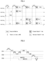
- FIG. 5 is a diagram for explaining a frame transmission operation based on CSMA/CA to which the present disclosure may be applied.
- a STA1 intends to transmit data to a STA2, and a STA3 is in a position capable of overhearing some or all of frames transmitted and received between the STA1 and the STA2.
- the STA3 may set a NAV timer for a frame transmission period (e.g., SIFS + CTS frame + SIFS + data frame + SIFS + ACK frame) that is continuously transmitted thereafter, using the duration information included in the RTS frame.
- a NAV timer for a frame transmission period (e.g., SIFS + data frame + SIFS + ACK frame) that is continuously transmitted thereafter, using the duration information included in the CTS frame.
- the STA3 may set the NAV accordingly.
- the STA3 may update the NAV timer using duration information included in the new frame. The STA3 does not attempt channel access until the NAV timer expires.
- the STA1 may transmit the data frame to the STA2 after SIFS from the time point when the reception of the CTS frame is completed.
- the STA2 may transmit an ACK frame as a response to the data frame to the STA1 after SIFS.
- the STA3 may determine whether the channel is being used through carrier sensing when the NAV timer expires. When the STA3 determines that the channel is not used by other terminals during DIFS after expiration of the NAV timer, the STA3 may attempt channel access after a contention window (CW) according to a random backoff has passed.
- CW contention window
- a PHY layer protocol data unit (PPDU) frame format is defined.
- a basic PPDU frame may include a Short Training Field (STF), a Long Training Field (LTF), a SIGNAL (SIG) field, and a Data field.
- STF Short Training Field
- LTF Long Training Field
- SIG SIGNAL
- Data field e.g., Data field
- the most basic (e.g., non-High Throughput (HT)) PPDU frame format may consist of only L-STF (Legacy-STF), L-LTF (Legacy-LTF), SIG field, and data field.
- PPDU frame format e.g., HT-mixed format PPDU, HT-greenfield format PPDU, VHT (Very High Throughput) PPDU, etc.
- STF, LTF, and SIG fields may be included between the SIG field and the data field (this will be described later with reference to FIG. 7 ).
- the STF is a signal for signal detection, automatic gain control (AGC), diversity selection, precise time synchronization, and the like
- the LTF is a signal for channel estimation and frequency error estimation.
- the STF and LTF may be referred to as signals for synchronization and channel estimation of the OFDM physical layer.
- the data field may include a SERVICE field, a physical layer service data unit (PSDU), and a PPDU TAIL bit, and may also include padding bits if necessary.
- Some bits of the SERVICE field may be used for synchronization of the descrambler at the receiving end.
- the PSDU corresponds to the MAC PDU defined in the MAC layer, and may include data generated/used in the upper layer.
- the PPDU TAIL bit may be used to return the encoder to a 0 state.
- Padding bits may be used to adjust the length of a data field in a predetermined unit.
- a null-data packet (NDP) frame format means a frame format that does not include a data packet. That is, the NDP frame refers to a frame format that includes a physical layer convergence procedure (PLCP) header part (i.e., STF, LTF, and SIG fields) in a general PPDU frame format and does not include the remaining parts (i.e., data field).
- PLCP physical layer convergence procedure
- a NDP frame may also be referred to as a short frame format.
- the basic PPDU format (IEEE 802.11a/g) includes L-LTF, L-STF, L-SIG and Data fields.
- the basic PPDU format may also be referred to as a non-HT PPDU format.
- VHT PPDU format (IEEE 802.11ac) additionally includes VHT SIG-A, VHT-STF, VHT-LTF, and VHT-SIG-B fields to the basic PPDU format.
- HE PPDU format (IEEE 802.11ax) additionally includes Repeated L-SIG (RL-SIG), HE-SIG-A, HE-SIG-B, HE-STF, HE-LTF(s), Packet Extension (PE) field to the basic PPDU format.
- R-SIG Repeated L-SIG
- HE-SIG-A HE-SIG-B
- HE-STF HE-LTF(s)
- PE Packet Extension
- Some fields may be excluded or their length may vary according to detailed examples of the HE PPDU format.
- the HE-SIG-B field is included in the HE PPDU format for multi-user (MU), and the HE-SIG-B is not included in the HE PPDU format for single user (SU).
- SU single user
- the HE trigger-based (TB) PPDU format does not include the HE-SIG-B, and the length of the HE-STF field may vary to 8 us.
- the Extended Range (HE ER) SU PPDU format does not include the HE-SIG-B field, and the length of the HE-SIG-A field may vary to 16us.
- FIGs. 8 to 10 are diagrams for explaining examples of resource units of a WLAN system to which the present disclosure may be applied.
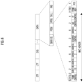
- FIG. 8 is a diagram illustrating an exemplary allocation of resource units (RUs) used on a 20 MHz band.
- RUs of various sizes that is, 26-RU, 52-RU, 106-RU, 242-RU, etc. are exemplified, but the specific size of these RUs may be reduced or expanded. Therefore, in the present disclosure, the specific size of each RU (i.e., the number of corresponding tones) is exemplary and not restrictive. In addition, within a predetermined bandwidth (e.g., 20, 40, 80, 160, 320 MHz, ...) in the present disclosure, the number of RUs may vary according to the size of the RU. In the examples of FIG. 9 and/or FIG. 10 to be described below, the fact that the size and/or number of RUs may be varied is the same as the example of FIG. 8 .
- 26-RU, 52-RU, 106-RU, 242-RU, 484-RU, and the like may be used in the example of FIG. 9 as well.
- 5 DC tones may be inserted at the center frequency
- 12 tones may be used as a guard band in the leftmost band of the 40MHz band
- 11 tones may be used as a guard band in the rightmost band of the 40MHz band.
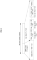
- FIG. 10 is a diagram illustrating an exemplary allocation of resource units (RUs) used on an 80 MHz band.
- 26-RU, 52-RU, 106-RU, 242-RU, 484-RU, 996-RU and the like may be used in the example of FIG. 10 as well.
- RU allocation of HE PPDUs and EHT PPDUs may be different, and the example of FIG. 10 shows an example of RU allocation for 80 MHz EHT PPDUs.
- HE PPDU 10 is the same in HE PPDU and EHT PPDU.
- EHT PPDU 23 DC tones are inserted into the DC band, and one 26-RU exists on the left and right sides of the DC band.
- one null subcarrier exists between 242-RUs rather than the center band, there are five null subcarriers in the EHT PPDU.
- one 484-RU does not include null subcarriers, but in the EHT PPDU, one 484-RU includes 5 null subcarriers.
- the MRU corresponds to a group of subcarriers (or tones) composed of a plurality of RUs, and the plurality of RUs constituting the MRU may be RUs having the same size or RUs having different sizes.
- a single MRU may be defined as 52+26-tone, 106+26-tone, 484+242-tone, 996+484-tone, 996+484+242-tone, 2X996+484-tone, 3X996-tone, or 3X996+484-tone.
- the 80 MHz subblock may use RU allocation other than the 996-tone RU.
- the first STA may transmit a first trigger-based (TB) PPDU based on the first RU
- the second STA may transmit a second TB PPDU based on the second RU.
- the first/second TB PPDUs may be transmitted to the AP in the same time duration.
- Information on the allocation of RUs may be signaled through HE-SIG-B in the HE PPDU format.
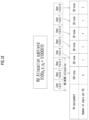
- FIG. 11 illustrates an example structure of a HE-SIG-B field.
- the common field may include information on RU allocation (e.g., RU assignment, RUs allocated for MU-MIMO, the number of MU-MIMO users (STAs), etc.)
- RU allocation e.g., RU assignment, RUs allocated for MU-MIMO, the number of MU-MIMO users (STAs), etc.
- the common field may include N*8 RU allocation subfields.
- One 8-bit RU allocation subfield may indicate the size (26, 52, 106, etc.) and frequency location (or RU index) of RUs included in the 20 MHz band.
- the value of the 8-bit RU allocation subfield is 01000y2yly0, it may indicate that one 106-RU and five 26-RUs are sequentially allocated from the leftmost to the rightmost in the example of FIG. 8 .
- multiple users/STAs may be allocated to the 106-RU in the MU-MIMO scheme.
- up to 8 users/STAs may be allocated to the 106-RU, and the number of users/STAs allocated to the 106-RU is determined based on 3-bit information (i.e., y2y1y0). For example, when the 3-bit information (y2y1y0) corresponds to a decimal value N, the number of users/STAs allocated to the 106-RU may be N+1.
- the set of user-specific fields includes information on how all users (STAs) of the corresponding PPDU decode their payloads.
- User-specific fields may contain zero or more user block fields.
- the non-final user block field includes two user fields (i.e., information to be used for decoding in two STAs).
- the final user block field contains one or two user fields.
- the number of user fields may be indicated by the RU allocation subfield of HE-SIG-B, the number of symbols of HE-SIG-B, or the MU-MIMO user field of HE-SIG-A.
- a User-specific field may be encoded separately from or independently of a common field.
- the user field of the first format (i.e., format for MU-MIMO allocation) may be constructed as follows. For example, out of all 21 bits of one user field, B0-B10 includes the user's identification information (e.g., STA-ID, AID, partial AID, etc.), B11-14 includes spatial configuration information such as the number of spatial streams for the corresponding user, B15-B18 includes Modulation and Coding Scheme (MCS) information applied to the Data field of the corresponding PPDU, B19 is defined as a reserved field, and B20 may include information on a coding type (e.g., binary convolutional coding (BCC) or low-density parity check (LDPC)) applied to the Data field of the corresponding PPDU.
- BCC binary convolutional coding
- LDPC low-density parity check
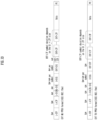
- FIG. 13 illustrates an example of a PPDU format to which the present disclosure may be applied.
- the PPDU of FIG. 13 may be referred as various names such as an EHT PPDU, a transmitted PPDU, a received PPDU, a first type or an Nth type PPDU.
- the PPDU or EHT PPDU of the present disclosure may be referred as various names such as a transmission PPDU, a reception PPDU, a first type or an Nth type PPDU.
- the EHT PPU may be used in an EHT system and/or a new wireless LAN system in which the EHT system is improved.
- the EHT-SIG is omitted compared to the EHT MU PPDU.
- the STA may perform UL transmission based on the EHT TB PPDU format.
- L-STF to EHT-LTF correspond to a preamble or a physical preamble, and may be generated/transmitted/received/acquired/decoded in the physical layer.
- a Subcarrier frequency spacing of L-STF, L-LTF, L-SIG, RL-SIG, Universal SIGNAL (U-SIG), EHT-SIG field (these are referred to as pre-EHT modulated fields) may be set to 312.5 kHz.
- a subcarrier frequency spacing of the EHT-STF, EHT-LTF, Data, and PE field (these are referred to as EHT modulated fields) may be set to 78.125 kHz.
- the transmitting STA may apply BCC encoding based on a coding rate of 1/2 to 24-bit information of the L-SIG field. Thereafter, the transmitting STA may obtain 48-bit BCC coded bits. BPSK modulation may be applied to 48-bit coded bits to generate 48 BPSK symbols. The transmitting STA may map 48 BPSK symbols to any location except for a pilot subcarrier (e.g., ⁇ subcarrier index -21, -7, +7, +21 ⁇ ) and a DC subcarrier (e.g., ⁇ subcarrier index 0 ⁇ ).
- a pilot subcarrier e.g., ⁇ subcarrier index -21, -7, +7, +21 ⁇
- DC subcarrier e.g., ⁇ subcarrier index 0 ⁇
- the version-independent bits of U-SIG may include a 1-bit UL/DL flag field.
- a first value of the 1-bit UL/DL flag field is related to UL communication, and a second value of the UL/DL flag field is related to DL communication.
- Preamble puncturing may be applied to the PPDU of Fig. 13 .
- Preamble puncturing may mean transmission of a PPDU in which no signal is present in one or more 20 MHz subchannels among the bandwidth of the PPDU.
- Preamble puncturing may be applied to a PPDU transmitted to one or more users.
- the resolution of the preamble puncturing may be 20 MHz for an EHT MU PPDU in an OFDMA transmission with a bandwidth greater than 40 MHz and in a non-OFDMA transmission with a bandwidth of 80 MHz and 160 MHz. That is, in the above case, puncturing for a subchannel smaller than 242-tone RU may not be allowed.
- the resolution of the preamble puncturing may be 40 MHz. That is, puncturing for subchannels smaller than 484-tone RU in 320 MHz bandwidth may not be allowed. Also, preamble puncturing may not be applied for the primary 20 MHz channel in EHT MU PPDU.
- the first field of the second U-SIG includes information on a 160 MHz bandwidth
- the second field of the second U-SIG includes information on preamble puncturing applied to a second 80 MHz band (i.e., information on a preamble puncturing pattern).
- the EHT-SIG following the first U-SIG may include information on preamble puncturing applied to the second 80 MHz band (i.e., information on a preamble puncturing pattern)
- the EHT-SIG following the second U-SIG may include information on preamble puncturing applied to the first 80 MHz band (i.e., information on a preamble puncturing pattern).
- U-SIG may be constructed in units of 20 MHz. For example, if an 80 MHz PPDU is constructed, the U-SIG may be duplicated. That is, the same 4 U-SIGs may be included in the 80 MHz PPDU. PPDUs exceeding 80 MHz bandwidth may include different U-SIGs.
- the EHT-SIG may include technical features of HE-SIG-B described through FIGS. 11 and 12 .
- EHT-SIG like the example of FIG. 8 , may include a common field and a user-specific field.
- the Common field of the EHT-SIG may be omitted, and the number of user-specific fields may be determined based on the number of users.
- multiple users of the EHT PPDU may decode the PPDU (e.g., the data field of the PPDU) based on OFDMA. That is, a plurality of users of the EHT PPDU may receive the PPDU (e.g., the data field of the PPDU) through different frequency bands.
- the EHT-STF of FIG. 13 may be used to enhance automatic gain control (AGC) estimation in a MIMO environment or an OFDMA environment.
- the EHT-LTF of FIG. 13 may be used to estimate a channel in a MIMO environment or an OFDMA environment.
- the PPDU (i.e., EHT PPDU) of FIG. 13 may be constructed based on an example of RU allocation of FIGS. 8 to 10 .
- the EHT PPDU transmitted on the 80 MHz band may be constructed based on the RU of FIG. 10 . That is, a RU location of EHT-STF, EHT-LTF, and data field included in the EHT PPDU may be determined as shown in FIG. 10 .
- the tone-plan for 80 MHz in FIG. 10 may correspond to two repetitions of the tone-plan for 40 MHz in FIG. 9 .
- the tone-plan for 160/240/320 MHz may be configured in the form of repeating the pattern of FIG. 9 or 10 several times.
- the receiving STA may determine the type of the received PPDU as non-HT, HT, and VHT PPDU based on the following. For example, when 1) the first symbol after the L-LTF signal is BPSK and 2) RL-SIG in which L-SIG is repeated is not detected, the received PPDU may be determined as non-HT, HT, and VHT PPDU.
- the PPDU of FIG. 13 may be used to transmit and receive various types of frames.
- the PPDU of FIG. 13 may be used for (simultaneous) transmission and reception of one or more of a control frame, a management frame, or a data frame.
- the U-SIG content is the same in both 20 MHz subchannels.
- the U-SIG content is the same in all non-punctured 20 MHz subchannels.
- the U-SIG content is the same on all non-punctured 20 MHz subchannels within each 80 MHz subblock and may be different from the U-SIG content in other 80 MHz subblocks.
- the U-SIG-1 part of the U-SIG of the EHT MU PPDU may include a PHY version identifier (B0-B2), BW (B3-B5), UL/DL (B6), BSS color (B7-B12), TXOP (B13-B19), Disregard (B20-B24), and Validate (B25).
- the U-SIG-2 part of the EHT MU PPDU may include PPDU type and compression mode (B0-B1), validate (B2), punctured channel information (B3-B7), validation (B8), EHT-SIG MCS (B9-B10), number of EHT-SIG symbols (B11-B15), CRC (B16-B19), and tail (B20-B25).
- the UL/DL field value is set to 0.
- the PPDU Type and Compression Mode (B0-B1) field value of the U-SIG-2 part is 0, this indicates DL OFDMA transmission.
- the PPDU Type and Compression Mode (B0-B1) field value of the U-SIG-2 part is 1, this indicates EHT SU transmission or EHT sounding NDP.
- the PPDU Type and Compression Mode (B0-B1) field value of the U-SIG-2 part is 2, this indicates non-OFDMA DL MU-MIMO transmission.
- the UL/DL field value is set to 1.
- the PPDU Type and Compression Mode (B0-B1) field value of the U-SIG-2 part is 0, this may indicate a TB PPDU (e.g., UL OFDMA or UL-non-OFDMA).
- the PPDU Type and Compression Mode (B0-B1) field value of the U-SIG-2 part is 1, this may indicate an EHT SU transmission or an EHT sounding NDP.
- 1 denotes a non-punctured subchannel
- x denotes a punctured subchannel.
- the puncturing granularity for the 80 MHz and 160 MHz PPDU bandwidths may be 20 MHz
- the puncturing granularity for the 320 MHz PPDU bandwidth may be 40 MHz.
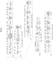
- FIG. 14 illustrates an example format of a trigger frame to which the present disclosure may be applied.
- a special user info field may be included in the trigger frame.
- the special user info field does not include user specific information, but includes extended common information that is not provided in the common info field.
- the user info list includes zero or more user info fields.
- FIG. 14 illustrates an example of an EHT variant user info field format.
- the RU allocation subfield may indicate the size and location of the RU/MRU. To this end, the RU allocation subfield may be interpreted together with the PS160 (primary/secondary 160MHz) subfield of the user info field and the UL BW subfield of the common info field.
- PS160 primary/secondary 160MHz
- the master AP initiates and controls MAP operations for transmission and reception between multiple APs.
- the master AP groups slave APs and manages links with slave APs so that information can be shared between the slave APs.
- the master AP manages information on the BSSs configured by the slave APs and information on STAs associated with the BSS.
- a master AP and a slave AP may perform direct transmission and reception with each other.
- a master AP and a STA may not perform direct transmission and reception with each other.
- a slave AP e.g., a slave AP associated with an STA
- a slave AP may perform direct transmission and reception with the STA.
- One of the slave APs may become a master AP.
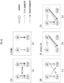
- FIG. 15(d) shows an AP selection method in which an AP with a good channel condition among adjacent APs performs transmission.
- Equation 1 PSR is the SR value of the trigger frame and the SIG field of the TB PPDU, and RPL may mean the received signal power.
- the interference situation of BSS AP/STA and/or OBSS AP/STA must be confirmed.
- the pre-procedure refers to a procedure for reporting and collecting information to be exchanged in advance for C-SR operation.
- APs/STAs may obtain channel information of BSS/OBSS APs/STAs based on the direction of the frame that is the target of the C-SR operation (e.g., DL direction or UL direction).
- a BSS STA may obtain channel information from an on-going packet or NDP sounding frame of an OBSS AP and transmit the obtained channel information to the BSS AP.
- a BSS STA may acquire channel information in RU units from an NDP sounding frame of an OBSS AP and report the acquired channel information in RU units to the BSS AP.
- the Sharing AP can select the Shared AP(s) candidate by collecting information about neighboring APs.
- the Sharing AP may select the Shared AP(s) from among the AP(s) whose channel status is busy.
- the C-SR setup procedure may include a procedure for selecting shared AP(s) to exchange C-SR data (before starting C-SR data transmission) and confirming whether C-SR data may be transmitted or received with the selected shared AP(s).
- the C-SR setup procedure may be performed before SIFS of the C-SR data transmission procedure.
- the data transmission procedure may include a procedure for transmitting a C-SR trigger frame (or a separate DL frame) for C-SR data transmission and a procedure for OBSS/BSS APs to transmit and receive C-SR data based on the C-SR trigger frame.
- the C-SR trigger frame may be configured based on the trigger frame illustrated in FIG. 14 .
- An AP/STA should acquire channel information of BSS/OBSS AP/STA(s) based on the direction of the frame to which the C-SR technique is to be applied (i.e., DL direction or UL direction).
- channel value may include at least one of RSSI (Received signal strength indication), RPI (Rx Power Indicator), ANPI (Avg Noise Power Indicator), IPI (Idle Power Indicator), RCPI (Rx Channel power Indicator) or RSNI (Rx Signal to Noise Indicator).
- the channel value measured by the BSS/OBSS AP/STA in the present disclosure may include the overall channel value for the indicated band (by the BSS/OBSS AP), or the channel value for the indicated/allocated RU(s).
- Method 2 relates to a method for obtaining channel information when performing UL reception of a BSS AP and DL transmission (hereinafter, "UL/DL") of an OBSS AP.
- UL/DL DL transmission
- the BSS AP may measure a channel value for a DL frame from the OBSS AP.
- a BSS AP may measure the channel value of an on-going packet (e.g., a beacon frame, etc.) of an OBSS AP.
- an on-going packet e.g., a beacon frame, etc.
- the BSS AP directly measures/obtains the channel value, a separate reporting procedure for the channel value may not be necessary.
- the BSS AP may obtain the channel value through the OBSS NDP sounding procedure. Since the measurement value feedback procedure for the OBSS NDP for C-SR in the UL/DL situation is not required, the NDP sounding procedure may be completed by the OBSS NDP transmission or the BSS AP's ACK transmission for the OBSS NDP transmission.
- the OBSS sounding procedure may include a procedure in which the BSS STA transmits feedback after the OBSS AP transmits NDP.
- Method 3 relates to a method of obtaining channel information when performing DL transmission of a BSS AP and UL reception of an OBSS AP (hereinafter, "DL/UL").
- DL/UL DL/UL
- interference information of an OBSS STA toward a BSS STA may be required for the BSS AP to transmit a DL frame using the C-SR technique.
- BSS STA(s) may measure and report channel values for all OBSS STAs supporting the C-SR procedure. At this time, BSS STA(s) may use on-going packets or OBSS NDP sounding procedure.
- Method 4 relates to a method for obtaining channel information when performing UL reception of a BSS AP and UL reception of an OBSS AP (hereinafter, "UL/UL").
- UL/UL UL/UL situation
- interference information of an OBSS AP directed toward a BSS AP may be required for a BSS STA to transmit a UL frame using the C-SR technique.
- the BSS STA may report the interference channel measurement value from the OBSS AP to the BSS AP. Accordingly, the OBSS AP may receive the channel measurement value from the BSS AP from the OBSS STA based on the OBSS STA. The OBSS AP may transmit the interference channel measurement value received from the OBSS STA to the BSS AP. For example, the OBSS AP may transmit the interference channel measurement value to the BSS AP through a control message over the air or backbone.
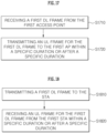
- the first STA may transmit an uplink (UL) frame for the first DL frame to the first AP within a specific duration or after a specific duration (S1720).
- UL uplink
- S1720 specific duration
- the specific duration may include a section in which a second DL frame is transmitted from the second AP to the second STA.
- the first STA may transmit a first UL frame (e.g., a UL ACK/BA frame, etc.) in the duration in which the second DL frame is transmitted from the second AP to the second STA.
- the first STA may be configured/indicated/defined not to transmit the first UL frame in the section in which the second DL frame is transmitted from the second AP to the second STA, and may transmit the first UL frame after the duration.
- the first AP may check whether the first STA has the SR capability. If it is confirmed that the first STA is an STA capable of performing the SR operation, the first AP may allow the transmission of the first UL frame within a specific duration. For example, the first AP may transmit information indicating that immediate transmission of the first UL frame is permitted (e.g., information indicating that transmission of the first UL frame is permitted after SIFS after the first DL frame is transmitted) to the first STA.
- information indicating that immediate transmission of the first UL frame is permitted e.g., information indicating that transmission of the first UL frame is permitted after SIFS after the first DL frame is transmitted
- the first STA may obtain the transmission power of the first UL frame based on the interference level of the second DL frame transmitted from the second AP to the second STA.
- the first STA may transmit the first UL frame to the first AP (within a specific duration) using the obtained transmission power.
- a dedicated channel may be allocated (by the first AP or/and the second AP) for transmitting the first UL frame.
- the first STA may transmit the first UL frame to the first AP through the dedicated channel.
- the second AP may transmit the second DL frame to the second STA on a channel other than the dedicated channel.
- the first STA may transmit the first UL frame independently/regardlessly in a specific duration. That is, the first STA may freely transmit the first UL frame through the allocated dedicated channel.
- the first STA may choose to transmit the first UL frame within a specific duration or after a specific time interval. For example, the first STA may transmit the first UL frame over the dedicated channel within the specific duration, but is not limited thereto. The first STA may transmit the first UL frame over the dedicated channel after the specific duration.
- the first AP or the second AP may transmit information to the first STA via a C-SR trigger frame, which sets a method for transmitting the first UL frame within a specific duration or after a specific duration (e.g., a method for setting a dedicated channel, a method for checking the SR capability of the STA to determine whether to allow transmission of the first UL frame within a specific duration, etc.).
- a C-SR trigger frame which sets a method for transmitting the first UL frame within a specific duration or after a specific duration (e.g., a method for setting a dedicated channel, a method for checking the SR capability of the STA to determine whether to allow transmission of the first UL frame within a specific duration, etc.).
- the method performed by the first STA described in the example of FIG. 17 may be performed by the first device (100) of FIG. 1 .
- one or more processors (102) of the first device (100) of FIG. 1 may be configured to receive a first DL frame from a first AP via one or more transceivers (106).
- the one or more processors (102) may be configured to transmit a first UL frame for the first DL frame to a second AP via one or more transceivers (106) within a specific duration or after a specific duration.
- one or more memories (104) of the first device (100) may store instructions for performing the method described in the example of FIG. 17 when executed by one or more processors (102).
- the second AP may transmit the second DL frame to the second STA.
- the second AP may transmit the second DL frame before the first AP transmits the first DL frame, and the second AP may transmit the second DL frame after the first AP completes transmitting the first DL frame.
- the first AP may receive the first UL frame for the first DL frame from the first STA within a specific duration or after a specific duration (S1820).
- the first AP may receive information from the second AP that sets how the first UL frame is transmitted within a specific duration or after a specific duration.
- the first AP may transmit information to the first STA that sets how the first UL frame is transmitted within a specific duration or after a specific duration.
- the method of transmitting the first UL frame within a specific duration or after a specific duration may be predefined.
- one or more memories (204) of the second device (200) may store instructions for performing the method described in the example of FIG. 18 when executed by one or more processors (202).
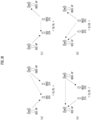
- a BSS/OBSS AP/STA performs a C-SR-based operation according to "DL/UL" (i.e., an operation according to the method 3 described above) as illustrated in (a) of FIG. 19 .
- the OBSS STA may transmit a UL frame including a UL ACK/BA frame, etc., in response to the DL frame transmitted by the OBSS AP (or, Shared AP).
- the BSS STA may not be able to smoothly receive the BSS DL frame due to the OBSS UL frame transmission (i.e., due to the interference effect according to the OBSS UL frame transmission).
- the following describes a method for transmitting a UL frame of an OBSS STA within a duration in which a BSS AP transmits a DL frame to a BSS STA.
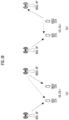
- Transmission of OBSS UL frames may be prohibited within a duration in which DL frames are transmitted from BSS AP to BSS STA.
- an OBSS AP when it transmits a DL frame that requires an ACK response, it may set the ACK policy for ACK/BA frame transmission to 'delayed ACK'.
- the OBSS AP may indicate/configure the OBSS STA to transmit a UL ACK/BA frame after a duration in which a DL frame is transmitted from the BSS AP to the BSS STA.
- the end time of each of the OBSS DL frame/packet and the BSS DL frame/packet may be aligned. That is, the end time of the OBSS DL frame/packet transmitted by the OBSS AP may be set/defined to coincide with the end time of the BSS DL frame/packet transmitted by the BSS AP.
- padding bits and/or dummy signals may be added to the DL frame with the shorter packet length.
- Embodiment 1 may be applied to C-SR based operation as well as C-SR based operation.
- Only STA(s) capable of performing SR-based operations may be configured/ defined/ indicated to transmit OBSS UL frames.
- An OBSS AP may allow transmission of OBSS UL frames only to OBSS STA(s) with SR capability.
- an OBSS AP may transmit a field (e.g., an 'immediate ACK' field, etc.) indicating that it allows immediate transmission of an OBSS UL frame for reception of an OBSS DL frame to OBSS STA(s) with SR capability.
- the OBSS STA(s) with SR capability may transmit an OBSS UL frame for the OBSS DL frame (received from the OBSS AP).
- a dedicated channel may be allocated separately for UL (control) frames (e.g., UL ACK frames, etc.).
- a BSS AP may transmit a DL frame to a BSS STA through a channel other than the dedicated channel.
- the OBSS AP may transmit the DL frame to the OBSS STA based on C-SR.
- the OBSS STA may transmit a UL frame for the DL frame to the OBSS AP through the dedicated channel.
- the BSS/OBSS AP may select at least one of the embodiments 1, 2, and 3, and notify the BSS/OBSS STA(s) to perform an operation according to the selected embodiment.
- the BSS/OBSS AP can apply/instruct/set operations/parameters based on at least one of Embodiments 1, 2, and 3 to the BSS/OBSS STA(s).
- Embodiments described above are that elements and features of the present disclosure are combined in a predetermined form. Each element or feature should be considered to be optional unless otherwise explicitly mentioned. Each element or feature may be implemented in a form that it is not combined with other element or feature.
- an embodiment of the present disclosure may include combining a part of elements and/or features. An order of operations described in embodiments of the present disclosure may be changed. Some elements or features of one embodiment may be included in other embodiment or may be substituted with a corresponding element or a feature of other embodiment. It is clear that an embodiment may include combining claims without an explicit dependency relationship in claims or may be included as a new claim by amendment after application.
- a storage medium may include a high-speed random-access memory such as DRAM, SRAM, DDR RAM or other random-access solid state memory device, but it is not limited thereto, and it may include a nonvolatile memory such as one or more magnetic disk storage devices, optical disk storage devices, flash memory devices or other nonvolatile solid state storage devices.
- a memory optionally includes one or more storage devices positioned remotely from processor(s).
- a memory or alternatively, nonvolatile memory device(s) in a memory include a non-transitory computer-readable storage medium.
Landscapes
- Engineering & Computer Science (AREA)
- Computer Networks & Wireless Communication (AREA)
- Signal Processing (AREA)
- Mobile Radio Communication Systems (AREA)
Applications Claiming Priority (2)
| Application Number | Priority Date | Filing Date | Title |
|---|---|---|---|
| KR20220068367 | 2022-06-03 | ||
| PCT/KR2023/007237 WO2023234646A1 (ko) | 2022-06-03 | 2023-05-26 | 무선랜 시스템에서 다중 액세스 포인트 동작 기반 시그널링 방법 및 장치 |
Publications (1)
| Publication Number | Publication Date |
|---|---|
| EP4535918A1 true EP4535918A1 (de) | 2025-04-09 |
Family
ID=89025363
Family Applications (1)
| Application Number | Title | Priority Date | Filing Date |
|---|---|---|---|
| EP23816307.5A Pending EP4535918A1 (de) | 2022-06-03 | 2023-05-26 | Verfahren und vorrichtung zur signalisierung auf der basis von mehrfachzugangspunktbetrieb in einem wlan-system |
Country Status (4)
| Country | Link |
|---|---|
| EP (1) | EP4535918A1 (de) |
| KR (1) | KR20250020507A (de) |
| CN (1) | CN119563373A (de) |
| WO (1) | WO2023234646A1 (de) |
Family Cites Families (5)
| Publication number | Priority date | Publication date | Assignee | Title |
|---|---|---|---|---|
| EP3020243A1 (de) * | 2013-07-11 | 2016-05-18 | Interdigital Patent Holdings, Inc. | Verfahren und vorgehensweisen zur planung von abschnittskanten- und nicht-abschnittskanten-stationsgruppen |
| JP2016526856A (ja) * | 2013-07-11 | 2016-09-05 | インターデイジタル パテント ホールディングス インコーポレイテッド | セクタ化調整をサポートするための方法および装置 |
| US10051588B2 (en) * | 2014-11-27 | 2018-08-14 | Mediatek Inc. | Collaborative OBSS interference mitigation for wireless communication systems |
| US10560962B2 (en) * | 2015-07-29 | 2020-02-11 | Lg Electronics Inc. | Method and apparatus for transmitting data in wireless communication system |
| TWI734725B (zh) * | 2016-01-07 | 2021-08-01 | 美商內數位專利控股公司 | 多使用者(mu)傳輸保護方法及裝置 |
-
2023
- 2023-05-26 KR KR1020247043133A patent/KR20250020507A/ko active Pending
- 2023-05-26 EP EP23816307.5A patent/EP4535918A1/de active Pending
- 2023-05-26 CN CN202380051347.6A patent/CN119563373A/zh active Pending
- 2023-05-26 WO PCT/KR2023/007237 patent/WO2023234646A1/ko not_active Ceased
Also Published As
| Publication number | Publication date |
|---|---|
| WO2023234646A1 (ko) | 2023-12-07 |
| CN119563373A (zh) | 2025-03-04 |
| KR20250020507A (ko) | 2025-02-11 |
Similar Documents
| Publication | Publication Date | Title |
|---|---|---|
| EP4358617A1 (de) | Verfahren und vorrichtung für zugangspunkt-zu-zugangspunkt-trigger und reaktion in einem wlan-system | |
| EP4486046A1 (de) | Verfahren und vorrichtung zum senden oder empfangen auf der basis eines netzwerkzuweisungsvektors in einem wlan-system | |
| EP4465689A1 (de) | Verfahren und vorrichtung zur kollaborativen erfassung in einem wlan-system | |
| EP4429319A1 (de) | Verfahren und vorrichtung zur durchführung eines erfassungsverfahrens in einem wlan-system | |
| US20240292262A1 (en) | Method and apparatus for collaborative sensing in wireless lan system | |
| US20250133437A1 (en) | Method and apparatus for transmitting and receiving protocol data unit-related information in wireless lan system | |
| EP4362542A1 (de) | Verfahren und vorrichtung zur durchführung von tid-zu-link-zuordnung in einem wlan-system | |
| US20240276525A1 (en) | Method and device for access point-to-access point trigger and response in wireless lan system | |
| EP4507257A1 (de) | Verfahren und vorrichtung zum senden oder empfangen von ppdu mit einer betriebsbezogenen präambel mit mehreren zugangspunkten in einem wlan-system | |
| EP4513838A1 (de) | Verfahren und vorrichtung für aggregierte übertragung und empfang einer protokolldateneinheit der physikalischen schicht in einem wlan-system | |
| EP4498743A1 (de) | Signalisierungsverfahren und -vorrichtung für ressourcenmultiplex-mehrfachzugriff auf basis des betriebs mehrerer zugangspunkte in einem wlan-system | |
| EP4404684A1 (de) | Verfahren und vorrichtung zum senden oder empfangen von zugangspunktbezogenen informationen in einem wlan-system | |
| EP4418797A1 (de) | Verfahren und vorrichtung zur dienstperiodenbasierten erfassung in einem wlan-system | |
| EP4387370A1 (de) | Verfahren und vorrichtung für messbezogenen aufbau in einem wlan-system | |
| EP4535856A1 (de) | Verfahren und vorrichtung zur auf mehrfachzugangspunktbetrieb basierenden signalisierung in einem wlan-system | |
| EP4525544A1 (de) | Verfahren und vorrichtung zur durchführung eines erfassungsverfahrens in einem wlan-system | |
| EP4529258A1 (de) | Verfahren und vorrichtung zur durchführung eines erfassungsverfahrens in einem wlan-system | |
| AU2023221188B2 (en) | Method and apparatus for performing sensing measurement based on trigger frame in wireless lan system | |
| EP4489504A1 (de) | Verfahren und vorrichtung zur durchführung eines erfassungsverfahrens in einem wlan-system | |
| EP4513795A1 (de) | Verfahren und vorrichtung zur durchführung einer auf präambelpunktierung basierenden kommunikation in einem wlan-system | |
| EP4415469A1 (de) | Verfahren und vorrichtung zur durchführung eines erfassungsverfahrens in einem wlan-system | |
| EP4404676A1 (de) | Verfahren und vorrichtung für sensing-bezogene abfragen in einem wlan-system | |
| EP4426051A1 (de) | Verfahren und vorrichtung zur durchführung von messungsmessungen in einem wlan-system | |
| EP4387334A1 (de) | Verfahren und vorrichtung zur durchführung eines erfassungsverfahrens in einem wlan-system | |
| US20250106733A1 (en) | Method and device for performing communication on basis of ht control field in wireless lan system |
Legal Events
| Date | Code | Title | Description |
|---|---|---|---|
| STAA | Information on the status of an ep patent application or granted ep patent |
Free format text: STATUS: THE INTERNATIONAL PUBLICATION HAS BEEN MADE |
|
| PUAI | Public reference made under article 153(3) epc to a published international application that has entered the european phase |
Free format text: ORIGINAL CODE: 0009012 |
|
| STAA | Information on the status of an ep patent application or granted ep patent |
Free format text: STATUS: REQUEST FOR EXAMINATION WAS MADE |
|
| 17P | Request for examination filed |
Effective date: 20241121 |
|
| AK | Designated contracting states |
Kind code of ref document: A1 Designated state(s): AL AT BE BG CH CY CZ DE DK EE ES FI FR GB GR HR HU IE IS IT LI LT LU LV MC ME MK MT NL NO PL PT RO RS SE SI SK SM TR |
|
| DAV | Request for validation of the european patent (deleted) | ||
| DAX | Request for extension of the european patent (deleted) |