EP4503408A1 - Stator manufacturing method - Google Patents
Stator manufacturing method Download PDFInfo
- Publication number
- EP4503408A1 EP4503408A1 EP23774522.9A EP23774522A EP4503408A1 EP 4503408 A1 EP4503408 A1 EP 4503408A1 EP 23774522 A EP23774522 A EP 23774522A EP 4503408 A1 EP4503408 A1 EP 4503408A1
- Authority
- EP
- European Patent Office
- Prior art keywords
- resin member
- mold
- stator
- case
- resin
- Prior art date
- Legal status (The legal status is an assumption and is not a legal conclusion. Google has not performed a legal analysis and makes no representation as to the accuracy of the status listed.)
- Pending
Links
Images









Classifications
-
- H—ELECTRICITY
- H02—GENERATION; CONVERSION OR DISTRIBUTION OF ELECTRIC POWER
- H02K—DYNAMO-ELECTRIC MACHINES
- H02K15/00—Processes or apparatus specially adapted for manufacturing, assembling, maintaining or repairing of dynamo-electric machines
- H02K15/12—Impregnating, moulding insulation, heating or drying of windings, stators, rotors or machines
- H02K15/121—Impregnating, moulding insulation, heating or drying of windings, stators, rotors or machines of cores
-
- B—PERFORMING OPERATIONS; TRANSPORTING
- B29—WORKING OF PLASTICS; WORKING OF SUBSTANCES IN A PLASTIC STATE IN GENERAL
- B29C—SHAPING OR JOINING OF PLASTICS; SHAPING OF MATERIAL IN A PLASTIC STATE, NOT OTHERWISE PROVIDED FOR; AFTER-TREATMENT OF THE SHAPED PRODUCTS, e.g. REPAIRING
- B29C45/00—Injection moulding, i.e. forcing the required volume of moulding material through a nozzle into a closed mould; Apparatus therefor
- B29C45/14—Injection moulding, i.e. forcing the required volume of moulding material through a nozzle into a closed mould; Apparatus therefor incorporating preformed parts or layers, e.g. injection moulding around inserts or for coating articles
- B29C45/1418—Injection moulding, i.e. forcing the required volume of moulding material through a nozzle into a closed mould; Apparatus therefor incorporating preformed parts or layers, e.g. injection moulding around inserts or for coating articles the inserts being deformed or preformed, e.g. by the injection pressure
- B29C45/14262—Clamping or tensioning means for the insert
-
- B—PERFORMING OPERATIONS; TRANSPORTING
- B29—WORKING OF PLASTICS; WORKING OF SUBSTANCES IN A PLASTIC STATE IN GENERAL
- B29C—SHAPING OR JOINING OF PLASTICS; SHAPING OF MATERIAL IN A PLASTIC STATE, NOT OTHERWISE PROVIDED FOR; AFTER-TREATMENT OF THE SHAPED PRODUCTS, e.g. REPAIRING
- B29C45/00—Injection moulding, i.e. forcing the required volume of moulding material through a nozzle into a closed mould; Apparatus therefor
- B29C45/14—Injection moulding, i.e. forcing the required volume of moulding material through a nozzle into a closed mould; Apparatus therefor incorporating preformed parts or layers, e.g. injection moulding around inserts or for coating articles
- B29C45/14065—Positioning or centering articles in the mould
-
- B—PERFORMING OPERATIONS; TRANSPORTING
- B29—WORKING OF PLASTICS; WORKING OF SUBSTANCES IN A PLASTIC STATE IN GENERAL
- B29C—SHAPING OR JOINING OF PLASTICS; SHAPING OF MATERIAL IN A PLASTIC STATE, NOT OTHERWISE PROVIDED FOR; AFTER-TREATMENT OF THE SHAPED PRODUCTS, e.g. REPAIRING
- B29C45/00—Injection moulding, i.e. forcing the required volume of moulding material through a nozzle into a closed mould; Apparatus therefor
- B29C45/14—Injection moulding, i.e. forcing the required volume of moulding material through a nozzle into a closed mould; Apparatus therefor incorporating preformed parts or layers, e.g. injection moulding around inserts or for coating articles
- B29C45/1418—Injection moulding, i.e. forcing the required volume of moulding material through a nozzle into a closed mould; Apparatus therefor incorporating preformed parts or layers, e.g. injection moulding around inserts or for coating articles the inserts being deformed or preformed, e.g. by the injection pressure
-
- B—PERFORMING OPERATIONS; TRANSPORTING
- B29—WORKING OF PLASTICS; WORKING OF SUBSTANCES IN A PLASTIC STATE IN GENERAL
- B29C—SHAPING OR JOINING OF PLASTICS; SHAPING OF MATERIAL IN A PLASTIC STATE, NOT OTHERWISE PROVIDED FOR; AFTER-TREATMENT OF THE SHAPED PRODUCTS, e.g. REPAIRING
- B29C45/00—Injection moulding, i.e. forcing the required volume of moulding material through a nozzle into a closed mould; Apparatus therefor
- B29C45/14—Injection moulding, i.e. forcing the required volume of moulding material through a nozzle into a closed mould; Apparatus therefor incorporating preformed parts or layers, e.g. injection moulding around inserts or for coating articles
- B29C45/14336—Coating a portion of the article, e.g. the edge of the article
- B29C45/14377—Coating a portion of the article, e.g. the edge of the article using an additional insert, e.g. a fastening element
-
- B—PERFORMING OPERATIONS; TRANSPORTING
- B29—WORKING OF PLASTICS; WORKING OF SUBSTANCES IN A PLASTIC STATE IN GENERAL
- B29C—SHAPING OR JOINING OF PLASTICS; SHAPING OF MATERIAL IN A PLASTIC STATE, NOT OTHERWISE PROVIDED FOR; AFTER-TREATMENT OF THE SHAPED PRODUCTS, e.g. REPAIRING
- B29C45/00—Injection moulding, i.e. forcing the required volume of moulding material through a nozzle into a closed mould; Apparatus therefor
- B29C45/14—Injection moulding, i.e. forcing the required volume of moulding material through a nozzle into a closed mould; Apparatus therefor incorporating preformed parts or layers, e.g. injection moulding around inserts or for coating articles
- B29C45/1459—Coating annular articles
-
- B—PERFORMING OPERATIONS; TRANSPORTING
- B29—WORKING OF PLASTICS; WORKING OF SUBSTANCES IN A PLASTIC STATE IN GENERAL
- B29C—SHAPING OR JOINING OF PLASTICS; SHAPING OF MATERIAL IN A PLASTIC STATE, NOT OTHERWISE PROVIDED FOR; AFTER-TREATMENT OF THE SHAPED PRODUCTS, e.g. REPAIRING
- B29C45/00—Injection moulding, i.e. forcing the required volume of moulding material through a nozzle into a closed mould; Apparatus therefor
- B29C45/14—Injection moulding, i.e. forcing the required volume of moulding material through a nozzle into a closed mould; Apparatus therefor incorporating preformed parts or layers, e.g. injection moulding around inserts or for coating articles
- B29C45/14639—Injection moulding, i.e. forcing the required volume of moulding material through a nozzle into a closed mould; Apparatus therefor incorporating preformed parts or layers, e.g. injection moulding around inserts or for coating articles for obtaining an insulating effect, e.g. for electrical components
-
- H—ELECTRICITY
- H02—GENERATION; CONVERSION OR DISTRIBUTION OF ELECTRIC POWER
- H02K—DYNAMO-ELECTRIC MACHINES
- H02K15/00—Processes or apparatus specially adapted for manufacturing, assembling, maintaining or repairing of dynamo-electric machines
- H02K15/02—Processes or apparatus specially adapted for manufacturing, assembling, maintaining or repairing of dynamo-electric machines of stator or rotor bodies
- H02K15/021—Magnetic cores
- H02K15/022—Magnetic cores with salient poles
-
- H—ELECTRICITY
- H02—GENERATION; CONVERSION OR DISTRIBUTION OF ELECTRIC POWER
- H02K—DYNAMO-ELECTRIC MACHINES
- H02K3/00—Details of windings
- H02K3/46—Fastening of windings on the stator or rotor structure
- H02K3/52—Fastening salient pole windings or connections thereto
- H02K3/521—Fastening salient pole windings or connections thereto applicable to stators only
- H02K3/522—Fastening salient pole windings or connections thereto applicable to stators only for generally annular cores with salient poles
-
- B—PERFORMING OPERATIONS; TRANSPORTING
- B29—WORKING OF PLASTICS; WORKING OF SUBSTANCES IN A PLASTIC STATE IN GENERAL
- B29C—SHAPING OR JOINING OF PLASTICS; SHAPING OF MATERIAL IN A PLASTIC STATE, NOT OTHERWISE PROVIDED FOR; AFTER-TREATMENT OF THE SHAPED PRODUCTS, e.g. REPAIRING
- B29C45/00—Injection moulding, i.e. forcing the required volume of moulding material through a nozzle into a closed mould; Apparatus therefor
- B29C45/14—Injection moulding, i.e. forcing the required volume of moulding material through a nozzle into a closed mould; Apparatus therefor incorporating preformed parts or layers, e.g. injection moulding around inserts or for coating articles
- B29C2045/1486—Details, accessories and auxiliary operations
- B29C2045/14934—Preventing penetration of injected material between insert and adjacent mould wall
-
- B—PERFORMING OPERATIONS; TRANSPORTING
- B29—WORKING OF PLASTICS; WORKING OF SUBSTANCES IN A PLASTIC STATE IN GENERAL
- B29L—INDEXING SCHEME ASSOCIATED WITH SUBCLASS B29C, RELATING TO PARTICULAR ARTICLES
- B29L2031/00—Other particular articles
- B29L2031/748—Machines or parts thereof not otherwise provided for
- B29L2031/7498—Rotors
Definitions
- the present disclosure relates to a stator manufacturing method.
- Resin molding for heat dissipation and insulation is performed to an inner face of a stator configuring a rotary electrical machine, for example an induction motor (see, for example, Japanese Patent Application Laid-Open ( JP-A) No. S60-002044 ).
- a stator assembly that contains a stator core wound with coils and a case covering the outer periphery of the stator core inside a mold, and injecting an insulating resin composition (hereafter referred to as a "molding resin”) inside the mold in a state pressed against both axial direction end portions of the stator assembly.
- an object of the present disclosure is to provide a stator manufacturing method capable of suppressing variation in product height and resin leakage without demanding a high dimensional accuracy during component manufacture.
- a stator manufacturing method includes a step of providing a stator assembly including a stator core having coils wound on plural teeth projecting from a yoke, and a case surrounding an outer periphery of the stator core, a step of arranging a ring-shaped resin member at least at one end portion in an axial direction of the case such that at least part of the resin member is crushed when pressed by a mold, a step of clamping the stator assembly inside the mold with the resin member arranged at the at least one end portion in a state in which the resin member is pressed, and a step of injecting a molding resin into the mold.
- the resin member is pressed and clamped by the mold prior to injecting the molding resin to proper locations on the stator assembly, with this meaning that a gap does not develop between the mold and the resin member, and the molding resin does not leak to the stator assembly outside.
- the dimension of the stator assembly after molding resin injection can be matched to the desired product dimension merely by forming the mold to match the desired product dimension, and variation in product dimension can be suppressed.
- a stator manufacturing method is the stator manufacturing method according to the first aspect of the present disclosure, wherein the resin member is configured from a thermoplastic resin, and a step is further included of pre-heating at least part of the mold including a portion that will contact the resin member.
- the crush portion can be softened and crushed using a simple method of causing the pre-heated mold to contact the resin member.
- a stator manufacturing method is the stator manufacturing method according to the first aspect or the second aspect of the present disclosure, wherein the resin member is a bus-bar unit, and the stator assembly includes plural bus-bars having one end portions electrically connected to end portions of the coils, with the bus-bars having other end portions that extend outside the stator assembly through the resin member.
- part of the bus-bar unit can be reused as the resin member, with this enabling the number of components to be reduced.
- a stator manufacturing method is the stator manufacturing method according to any one of the first aspect to the third aspect of the present disclosure, wherein the resin member includes a first ring-shaped projection formed at least at one or other face from out of a face that contacts the case or a face on the opposite side to the face that contacts the case.
- a liquid-tight state can be reliably achieved at least at one out of the contact portion between the resin member and the mold, or the contact portion between the resin member and the case, thereby enabling resin leakage to be more reliably suppressed.
- a stator manufacturing method is the stator manufacturing method according to any one of the first to fourth aspects of the present disclosure, wherein the case includes a second ring-shaped projection at a face that contacts the resin member.
- the second ring-shaped projection provided to the case actively deforms the resin member, thereby enabling a liquid-tight state to be reliably achieved between the case and the resin member.
- a stator manufacturing method is the stator manufacturing method according to any one of the first aspect to the fifth aspect of the present disclosure, wherein the resin member includes a tongue piece that extends along an inner peripheral face of the case, and an indentation able to accommodate entry of a leading end portion of the tongue piece is provided to an inner peripheral face of the case, and a step is further included of using the mold to press the resin member against the case and to fit a leading end of the tongue piece into the indentation.
- the stator manufacturing method as described above is configured to enable fixing between the case and the resin member to be performed at the same time as the stator assembly is being clamped by the mold.
- a stator manufacturing method is the stator manufacturing method of any one out of the first aspect to the sixth aspect of the present disclosure, wherein the case is configured from a resin, and the resin member is part of the case.
- the resin member forms part of the case, and so there is no need to separately prepare the resin member.
- the stator manufacturing method includes a step of providing a stator assembly including a stator core having coils wound on plural teeth projecting from a yoke, a step of arranging a ring-shaped resin member at least at one end portion in an axial direction of the stator core such that at least part of the resin member is crushed when pressed by a mold, a step of clamping the stator assembly inside the mold with the resin member arranged at the at least one end portion in a state in which the resin member is pressed, and a step of injecting a molding resin into the mold.
- the resin member is pressed and clamped by the mold prior to injecting molding resin to proper locations on the stator assembly, with this meaning that a gap does not develop between the mold and the resin member, and the molding resin does not leak to the stator assembly outside. Moreover, the resin member is crushed, and so the dimension of the stator assembly after molding resin injection can be matched to the desired product dimension merely by forming the mold to match the desired product dimension, and variation in product dimension can be suppressed.
- a stator manufacturing method is the stator manufacturing method according to the eighth aspect of the present disclosure, wherein the mold includes an upper mold and a lower mold, and the resin member includes a ring-shaped rib that is provided on an outer peripheral face of the resin member and that is directly clamped between the upper mold and the lower mold when clamped inside the mold.
- stator manufacturing method as described above, a structure is adopted in which the ring-shaped rib is directly clamped by the upper mold and the lower mold, with this meaning that a liquid-tight state can be achieved between the mold and the resin member without separate preparation of a case to cover the stator core.
- the stator manufacturing method of the present disclosure is configured so as to enable variation in product height and resin leakage to be suppressed without demanding high dimensional accuracy during component manufacture.
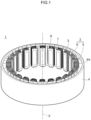
- Fig. 1 is a perspective view illustrating an example of a stator assembly employed in the stator manufacturing method according to a first exemplary embodiment of the present disclosure.
- the stator manufacturing method according to the present exemplary embodiment may mainly be employed to execute resin molding on part of a stator assembly 1 configuring part of an inner rotor type motor, as illustrated in Fig. 1 .
- the stator assembly 1 includes, as illustrated in Fig. 1 , at least a stator core 2, coils 3, and a case 4.
- the stator assembly may configure part of a motor other than an inner rotor type motor such as, for example, an axial type motor.
- the inner rotor type motor may, for example, be a three-phase motor.
- the stator core 2 may be configured by stacking plural sheets of iron core pieces (core pieces) each configured from an electromagnetic steel sheet.
- the stator core 2 may be configured as a ring-shaped member having a center axis X, and may include a yoke 5 formed in a ring shape, for example a circular cylinder shape, and plural (24 in Fig. 1 ) teeth 6 that project toward the inside from the inner peripheral face of the yoke 5.
- the plural teeth 6 are formed at a substantially uniform spacing from each other in a row along the circumferential direction of the stator core 2, and slots 7 may be respectively formed between adjacent of the teeth 6.
- the number of poles and the number of slots of the stator assembly 1 illustrated in Fig. 1 is merely an example thereof, and there is no limitation thereto.
- an extension direction of the center axis X will sometimes simply be referred to as "axial direction" below.
- the coils 3 may be spirally wound around the plural teeth 6.
- An insulator 8 may be interposed between each of the coils 3 and each of the teeth 6.
- the coils 3 may, for example, be configured from a wire made from a wire member of copper, aluminum, silver, or an alloy thereof, covered by an insulating covering film of enamel or the like.
- the wire is illustrated for an example of a round wire in Fig. 1 , however a fattened angular wire, a hexagonal wire, or the like may be employed.
- the same number of coils 3 may be included as coils for each of the three-phases (specifically the U-phase, V-phase, and W-phase).
- these coils 3 are wound around the periphery of the teeth 6 so as to form substantially elongated rectangular shapes having long sides along the axial direction of the stator core 2 when viewed along a radial direction of the stator core 2.
- a coil end 3A configuring and end portion of each of the coils 3 may be pulled out from one axial direction end of each of the slots 7 toward the slot 7 outside.
- the coils 3 are illustrated for an example configured by winding a single strand of electric wire, however plural strands of the electric wire may be wound.
- another insulating member may be employed therefor, such as for example insulating paper or wax.
- the case 4 is a member for surrounding the outer periphery of the stator core 2, and may be configured from a high rigidity material such as, for example, a metal plate having a specific thickness.
- a high rigidity material such as, for example, a metal plate having a specific thickness.
- Various shapes may be adopted for the external profile of the case 4, such as a completely tubular shape without a bottom at either axial direction end, a bottomed tube shape having a bottom at one axial direction as illustrated in Fig. 1 , or the like.
- the case 4 in the example of the present exemplary embodiment may be a bottomed tube shape set with an inner diameter to match an outer diameter of the stator core 2.
- a support projection 4B see Fig.
- an axial direction length of the case 4 may be set shorter than the axial direction length of the manufactured stator.
- Fig. 2 is a perspective view illustrating a state in which a resin member has been attached to the stator assembly illustrated in Fig. 1 .
- Fig. 3 is a cross-section sectioned along line A-A of Fig. 2 .
- a ring-shaped resin member 10 is arranged at least at one of the two axial direction ends of the stator assembly 1 having the above configuration, as illustrated in Fig. 2 .
- an example is illustrated in which the resin member 10 is arranged at one axial direction end of the stator assembly 1.
- the resin member 10 can be configured from a resilient resin formed in a circular ring shape so as to at least cover an axial direction one end portion 4A of the case 4.
- a case contact face 10A that opposes an end face of the case 4 may be configured as a substantially flat face on the circular ring-shaped resin member 10 so as to contact the entire periphery of the end face of the case 4.
- a step portion 10B to fit inside the one end portion 4A of the case 4 may be provided at the inside of the case contact face 10A of the resin member 10, and the resin member 10 may be attached by fitting this step portion 10UB inside the case 4.
- case 4 and the resin member 10 do not necessarily have a fitting structure using the step portion 10B as described above.
- an adhesive or the like may be employed to fix the one end portion 4A of the case 4 and the case contact face 10A together, or a structure may be adopted in which the resin member 10 is simply placed on the one end portion 4A of the case 4 without being fixed thereto.
- the resin member 10 of the present exemplary embodiment is illustrated for a circular ring-shaped example, there is no limitation to being a perfectly circular ring shape.
- the resin member 10 may be matched to the shape of the stator assembly 1 or the like and, for example, may have an elliptical shape, may be a ring shape having a projection and a recess that extend in a radial direction at respective parts of the outer peripheral face and the inner peripheral face thereof, or may be ring shape formed with an indentation or a through hole at a freely selected position thereon.
- a resilient insulating resin and in particular a thermoplastic resin, may be employed in the resin member 10.
- Polyphenylene sulfide (PPS) is, for example, preferably adopted as such a thermoplastic resin.
- the thermoplastic resin include not only PPS, but also polyethylene terephthalate (PET), polypropylene (PP), polyether ether ketone (PEEK), polybutylene terephthalate (PBT), a liquid crystal polymer (LCP), polyphthalamide (PPA), polyether ketone (PEK), polysulfone (PSU) / polyethersulfone (PES), polyether imide (PEI), polyamide-imide (PAI), modified polyphenylene ether (m-PPE), polyamide (PA), and combinations thereof, and in some cases fibers such as glass fibers may be added thereto.
- PET polyethylene terephthalate
- PP polypropylene
- PEEK polyether ether ketone
- PBT polybutylene ter
- resins such as polyimide (PI), fluororesins, polycarbonate (PC), polybutylene terephalate (PBT), polyethylene (PE), polyoxymethylene (POM), polystyrene (PS), polyarylate (PAR), polysulfone (PSF), ABS resins, polyethylene terephthalate (PET), and the like employed either singly or in a combination thereof.
- PI polyimide
- PC polycarbonate
- PBT polybutylene terephalate
- PE polyethylene
- POM polyoxymethylene
- PS polystyrene
- PAR polyarylate
- PSF polysulfone
- ABS resins polyethylene terephthalate (PET), and the like employed either singly or in a combination thereof.
- a crush portion 11 which is a portion mainly crushed when pressed by a mold 20, described later, may be provided to the face of the resin member 10 on the opposite side to the case contact face 10A.
- the crush portion 11 may, for example as illustrated in Fig. 3 , be a zone that extends in an axial direction by a specific length H (for example from 0.1 mm to 0.5 mm) on a face of the resin member 10 on the opposite side to the case contact face 10A.
- H for example from 0.1 mm to 0.5 mm
- the crush portion 11 is defined as being the portion of the resin member 10 where the maximum pressing force acts when pressed by the mold 20.
- the portion of the resin member 10 crushed when pressed by the mold 20 is not limited to only the portion indicated as the crush portion 11 and, for example, the present disclosure also encompasses the resin member 10 as a whole in cases in which resin member 10 is crushed substantially evenly.
- the length H of the crush portion 11 may be set in consideration of axial direction undulations and variation that might be present in the case 4 and the resin member 10.
- the length H of the crush portion 11 is set to a value larger than the sum thereof and may, for example, be set to 0.3 mm. Leakage of resin and variation in product dimension can be suppressed even when there is some undulations and variation in the case and the resin member 10 by adjusting the length H of the crush portion 11 in this manner.
- the axial direction length of the resin member 10 excluding the crush portion 11 is a length that may be adjusted such that a length when added to the axial direction length of the case 4 when attached to the one end portion 4A of the case 4 is the same as the axial direction length of the stator being manufactured.
- the stator assembly 1 may further include plural bus-bars 12 for performing electrical connection of the coils 3.
- the bus-bars 12 may be configured including one end portions 12A electrically connected to the coil ends 3A that extend out from the slots 7, and other end portions 12B on the opposite side to the one end portions 12A and extending outside the stator assembly 1. At least part of intermediate portions of the bus-bars 12 may be guided inside the resin member 10.
- the bus-bars 12 and the resin member 10 may accordingly be integrally formed as a bus-bar unit 13.
- the resin member 10 according to the present exemplary embodiment may be formed by utilizing part of the bus-bar unit 13.
- the bus-bars 12 of the present exemplary embodiment may be plural substantially circular arc shaped wiring to match the phases of the coils 3.
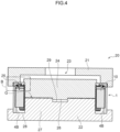
- Fig. 4 is a schematic cross-section illustrating an example of a device to execute the stator manufacturing method according to the first exemplary embodiment of the present disclosure.
- resin molding can be implemented using the mold 20.
- the mold 20 may include an upper mold 21 and a lower mold 22.
- the resin molding may be executed by clamping the stator assembly 1 including the above described resin member 10 in the axial direction using the upper mold 21 and the lower mold 22.
- the upper mold 21 may be configured from a substantially circular plate shaped member having an injection pathway 23 provided inside, and may have an outer diameter dimension that is larger than an outer diameter of the stator assembly 1.
- the upper mold 21 may be provided with a substantially circular pillar shaped upper projection 24 provided at a central portion of a face opposing the lower mold 22, and with an upper indentation 25 that is formed in substantially circular ring shape so as to surround the outer periphery of positions where the upper projection 24 is provided and that is capable of housing part of the stator assembly 1 including the above described resin member 10.
- the injection pathway 23 may be formed inside the upper mold 21 so as to connect between a face of the upper mold 21 on the opposite side to the face thereof opposing the lower mold 22, and one or plural locations inside the upper indentation 25.
- a surface on the leading end side of the upper projection 24 is configured by a substantially flat face, and a positioning projection 26 for performing positioning in a direction intersecting with the axial direction of the upper mold 21 and the lower mold 22 may be provided to a substantially central portion of the upper projection 24.
- the lower mold 22 may be configured from a substantially circular plate shaped member having an external dimension about the same as the upper mold 21.
- the lower mold 22 may be provided with a lower projection 27 provided at a center portion of the face opposing the upper mold 21 and having a leading end portion capable of contacting a leading end portion of the upper projection 24, and a lower indentation 28 that is formed in a substantially circular ring shape so as to surround the outer periphery of positions where the lower projection 27 is provided and that is capable of housing part of the stator assembly 1 including the above described resin member 10.
- a surface on the leading end side of the lower projection 27 is configured by a substantially flat face similar to the surface on the leading end side of the upper projection 24, and a positioning indentation 29 into which the positioning projection 26 of the upper mold 21 fits may be provided to a substantially central portion of the lower projection 27.
- the external profile of the upper mold 21 and the lower mold 22 is not limited thereto, and they may, for example, be formed as square shaped members.
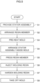
- Fig. 5 is a flowchart illustrating an example of the stator manufacturing method according to the first exemplary embodiment of the present disclosure.
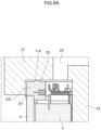
- Figs. 6 are expanded views on arrow B of Fig. 4 , with Fig. 6A illustrating a state prior to the mold pressing the resin member and Fig. 6B illustrating a state in which the mold has pressed the resin member.
- Explanation follows regarding an example of the stator manufacturing method according to the present exemplary embodiment for performing resin molding on the above described stator assembly 1 using the same mold 20 as above described.
- Cast molding and injection molding may be adopted as specific resin molding methods.
- a thermoset resin such as an epoxy resin or phenolic resin or a thermoplastic resin may be employed as a molding resin MR (see Fig. 7 ) employed in the resin molding.
- a stator assembly 1 such as illustrated in Fig. 1 is provided (step S1).
- the resin member 10 is arranged at one axial direction end portion of the stator assembly 1 (step S2).
- the case contact face 10A of the resin member 10 may be contacted against the one end portion 4A of the case, and the resin member 10 may be substantially fixed to the stator assembly 1 by a step portion 10B being fitted inside the case 4.
- pre-heating of the mold 20 is performed either after steps S1 and S2, or in parallel to these steps.
- This pre-heating may be executed at least on part of the mold 20 including at least the portion thereof for contacting against the resin member 10.
- the entire upper mold 21 is pre-heated.
- step S4 the upper mold 21 may, as illustrated in Fig. 6A , be in a state in which part of the upper indentation 25 is contacted against the crush portion 11 of the resin member 10. In such cases a slight gap G (see Fig. 4 ) is formed between the leading end of the upper projection 24 of the upper mold 21 and the leading end of the lower projection 27 of the lower mold 22 (see Fig. 4 ).
- step S5 When the stator assembly 1 has been arranged in the mold 20, next the crush portion 11 of the resin member 10 is pressed by the upper mold 21 (step S5) by at least one of the upper mold 21 or the lower mold 22 being moved in the direction such that both members are brought relatively closer to each other.
- the gap G is filled by this movement, the upper projection 24 and the lower projection 27 make contact, and the stator assembly 1 arranged between the upper mold 21 and the lower mold 22 is clamped at a specific pressure inside the mold 20.
- the gap G and the axial direction length H of the crush portion 11 are substantially the same as each other and, for example, may be 0.3 mm.
- the upper mold 21 is accordingly moved such that the entire crush portion 11 is crushed.
- the crush portion 11 crushed by the upper mold 21 is softened by heat from the upper mold 21, and moves toward the inner peripheral side or the outer peripheral side of the resin member 10.
- a ring-shaped space D1 to allow the softened resin member 10 to move toward the outside may be set in the upper indentation 25 of the upper mold 21 at an outer peripheral portion of the resin member 10. This means that most of the crush portion 11 pressed at step S5 thereby moves toward the outer peripheral side of the resin member 10 so as to fill the space D1 portion, as illustrated in Fig. 6B .
- the crush portion 11 may be softened before the stator assembly 1 is arranged in the mold 20, or a mode may be adopted in which the crush portion 11 is plastically deformed by pressing pressure of the upper mold 21 alone.
- the axial direction length between the upper indentation 25 and the lower indentation 28 in a state in which the upper projection 24 and the lower projection 27 have been brought into contact may be set so as to be the same as a setting length of the stator to be manufactured.
- the stator assembly 1 clamped between the upper indentation 25 and the lower indentation 28 is thereby clamped by the mold 20, enabling adjustment to a desired height.
- the axial direction length of the stator manufactured by the method according to the present exemplary embodiment is able to be decided based on the dimensions of the mold 20.
- next injection of the molding resin MR starts (step S6).
- Injection of the molding resin MR is performed by actuating a feed source connected to the injection pathway 23, for example a plunger, and injecting the molding resin MR via the injection pathway 23 mainly into the slots 7. Due to the upper mold 21 being pressed against the resin member 10 at step S5, these portions are placed in liquid-tight contact by the resilient force of the resin member 10, and so the molding resin MR that has been injected does not leak outside.
- a feed source connected to the injection pathway 23, for example a plunger
- step S7 When injection of the molding resin MR has been completed, the injected molding resin MR is hardened (step S7). Hardening of the molding resin MR may be performed by heating the molding resin MR using a known heating means (for example, by actuating a heater arranged inside the mold 20). When hardening of the molding resin MR has been completed, the mold 20 is taken off the stator assembly 1 (step S8), with this completing one cycle of manufacturing steps.
- Fig. 7 is a cross-section illustrating a state after resin molding has been performed on the stator assembly illustrated in Fig. 3 .
- the stator assembly 1 that has been subjected to resin molding through the cycle of steps described above is in a state in which all faces at the peripheral inside of the case 4 and the resin member 10 are covered by the molding resin MR, as illustrated in Fig. 7 .
- the dimensional accuracy of the product after resin molding can be raised, while suppressing the dimensional accuracy demanded in other members to a low level.
- resin can be prevented from leaking out when resin molding is performed by the resin member 10 having a specific resilience being contacted against the mold 20.
- stator manufacturing method of the present disclosure and the resin member 10 and the like illustrated in the first exemplary embodiment described above, may also be modified.
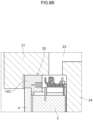
- Figs. 8 are expanded diagrams corresponding to Figs. 6 and illustrating a first modified example of the method according to the first exemplary embodiment, with Fig. 8A illustrating a state prior to the mold pressing the resin member, and Fig. 8B illustrating a state in which the mold has pressed the resin member.
- the crush portion 11 of the resin member 10 was formed so as to extend the entire face on the opposite side to the case contact face 10A by the specific length H, with this end face formed as a flat face.
- a configuration including a ring-shaped projection 11A as illustrated in Fig. 8A is adopted in place thereof.
- the ring-shaped projection 11A is an example of a first ring-shaped projection, and may be configured by part of the resin member 10C, and may be formed in a circular ring shape around the entire periphery of the face on the opposite side to the case contact face 10A.
- the ring-shaped projection 11A in Fig. 8A is illustrates an example of which only one is formed thereof, however plural may be formed thereof, spaced apart at a specific spacing.
- the height of the ring-shaped projection 11A is not necessarily uniform around the circumferential direction. Similar applies to a ring-shaped projection 11B and a ring-shaped projection 4C described later.
- the resin member 10C serves as a crush portion, and by adopting a configuration including the ring-shaped projection 11A on the face on the opposite side to the case contact face 10A, the volume of the portion crushed by the mold 20 can be made smaller than the crush portion 11 described above.
- the ring-shaped projection 11A portion is preferentially crushed when the resin member 10C is pressed by the mold 20, and so the ring-shaped projection 11A is reliably crushed around the entire periphery, enabling the liquid-tightness of this portion to be predictably secured.
- Fig. 9 is an expanded diagram corresponding to Figs. 6 and illustrates a second modified example of the method according to the first exemplary embodiment.
- a resin member 10D of the second modified example employs a ring-shaped projection 11B that projects downward on the case contact face 10A of the resin member 10D as another example of a first ring-shaped projection.
- the ring-shaped projection 11B is preferentially crushed when the stator assembly 1 is clamped inside the mold 20.
- the height direction length of the resin member 10D may be adjusted such that this contact face is also crushed when clamped in the mold 20, or this contact face may be surface machined in advance so as to match the face of the upper mold 21 being contacted.
- Fig. 10 is an expanded diagram corresponding to Figs. 6 and illustrates a third modified example of the method according to the first exemplary embodiment.
- a ring-shaped projection 4C may be provided to the one end portion 4A of the case 4 as an example of a second ring-shaped projection.
- the projection 4C presses the case contact face 10A of a resin member 10E when the resin member 10E is pressed by the upper mold 21, enabling a function in which the case contact face 10A is preferentially crushed.
- the case contact face 10A portion of the resin member 10E functions as a crush portion 11C.
- the resin member 10E of the present modified example may include configuration substantially similar to that of the resin member 10 according to the above exemplary embodiments.
- Adopting the configurations illustrated for the second and third modified examples enable liquid-tightness between the case 4 and the resin members 10D and 10E to be predictably secured.
- the ring-shaped projection 4C serving as an example of the second ring-shaped projection may be adopted irrespective of whether or not there is a ring-shaped projection 11A or 11B serving as an example of the first ring-shaped projection.
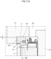
- Figs. 11 are expanded diagrams corresponding to Figs. 6 and illustrate a fourth modified example of the method according to the first exemplary embodiment, with Fig. 11A illustrating a state prior to the mold pressing the resin member, and Fig. 11B illustrating a state in which the mold has pressed the resin member.
- the first exemplary embodiment described above is an example illustrated in which, when arranging the resin member 10 in the stator assembly 1, the step portion 10B provided to the resin member 10 is fitted together with the inner peripheral face of the case 4 and both parties fixed together, however a fixing structure described in the following fourth modified example may be employed in place thereof.
- a fixing structure described in the following fourth modified example may be employed in place thereof.
- a tongue piece 14 that extends along the inner peripheral face of the case 4 is formed to the leading end of the step portion 10B of a resin member 10F, and an indentation 15 is formed at a position on the inner peripheral face of the case 4 near to the one end portion 4A of the case.
- the resin member 10F provided with the tongue piece 14 is attached to the case 4, in order to make contact between the leading end of the tongue piece 14 and an end face of the stator core 2, attachment is made in a state in which there is a gap formed between the one end portion 4A of the case 4 and the case contact face 10A.
- the tongue piece 14 may be formed in a ring shape similar to the step portion 10B, and may be formed in a form in which plural arms extend downward from the step portion 10B.
- the indentation 15 may be arranged to match the position of the tongue piece 14.
- a step as illustrated in Fig. 11B is executed to press the resin member 10F against the case 4 using the upper mold 21, and to fit the leading end of the tongue piece 14 inside the indentation 15.
- the resin member 10F is moved in the direction to approach the case 4 either before or at the same time as the crush portion 11 is being crushed.
- the leading end portion of the tongue piece 14 moves so as to escape from this end face toward the indentation 15 and fits into the indentation 15.
- the leading end of the tongue piece 14 is fitted together with the indentation 15 and the resin member 10F and the case 4 are fixed together during the course of performing resin molding, and so there is no longer a need to execute a separate step to fix the resin member 10F and the case 4 together.
- the two parts can be firmly fixed even in cases in which there is low cohesion between the resin member 10F and the case 4 due to the effects of undulations or the like.
- the case 4 is formed from a high rigidity member, for example metal, and the resin member 10, 10C to 10F is brought into contact with the case 4, however the case 4 may be formed with a resin, for example with a resin similar to that of the resin member 10, 10C to 10F described above.
- the resin members 10, 10C to 10F may each form part of the case 4. Configuring the resin members 10, 10C to 10F as part of the case 4 enables a reduction in the number of components and manufacturing man-hours.
- the axial direction length of the case 4 may be set longer than the product dimension, similarly to the resin member 10, 10C to 10F described in the above exemplary embodiment and each of the modified examples.
- a projection may also be provided to an end portion of the resin member configured by part of the case 4, similarly to the projection 11 A provided to the resin member 10C of the first modified example.
- the resin members 10, 10C to 10F illustrated above in the first exemplary embodiment and each of the modified examples each include the case contact face 10A that contacts the one end portion 4A of the case 4, and are configured such that at least part thereof is crushed when pressed by the mold 20.
- the resin member utilized in the method of the present disclosure does not necessarily contact an end portion of the case.
- a stator manufacturing method employing a resin member that does not contact the one end portion 4A of the case 4 as a second exemplary embodiment of the present disclosure.
- the second exemplary embodiment illustrated below may employ each configuration described above in the method according to the first exemplary embodiment described, except for in the shape of the resin member, and specifically the same overall configuration may be employed for a stator assembly and for a device to execute the stator manufacturing method.
- the same reference numerals will be appended to similar portions to those described in the first exemplary embodiment and explanation thereof will be omitted, with description focusing only on the portions modified from the first exemplary embodiment described above.
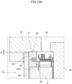
- Figs. 12 are expanded diagrams corresponding to Figs. 6 and illustrate an example of a device to execute the stator manufacturing method according to the second exemplary embodiment of the present disclosure, with Fig. 12A illustrating a state prior to the mold pressing the resin member, and Fig. 12B illustrating a state in which the mold has pressed the resin member.
- a resin member 30 prepared for such manufacture differs from that of the first exemplary embodiment in that the structure employed does not contact a one end portion 4A of a case 4D, but contacts an axial direction one end portion 2A of the stator core 2.
- the resin member 30 can be configured from a resilient resin formed in a circular ring shape so as to cover an axial direction one end portion 2A of the stator core 2.
- a stator core contact face 30A of the circular ring-shaped resin member 30 for contacting the stator core 2 is able to contact the stator core 2 mainly around the entire periphery of a portion configuring a yoke 5.
- the case 4D included in a stator assembly 1A may include a one end portion configured with part thereof extending to as to partially cover the outside of the resin member 30.
- the inner peripheral face of the case 4D and the outer peripheral face of the resin member 30 may be in a closely adhered state.
- the resin member 30 having at least part thereof covered at the outside by the case 4D is able to be supported by the one end portion 2A of the stator core 2 and the inner peripheral face of the case 4D.
- the face of the resin member 30 on the opposite side to the stator core contact face 30A is able to function as a crush portion 31 that is a portion mainly crushed when pressed by the mold 20.
- a length H of the crush portion 31 may be set in consideration of axial direction undulations and variation that might be present in the stator core 2 and the resin member 30. As a specific example, for example in a case in which the axial direction dimensional tolerances of the stator core 2 and the resin member 30 are each respectively set to ⁇ 0.1 mm, then the length H of the crush portion 31 is set to a value larger than the sum thereof and may, for example, be set to 0.3 mm.
- step S1 When resin molding the stator assembly 1A having one axial direction end portion supporting the resin member 30, the cycle of steps illustrated in Fig. 5 may be executed similarly to in the first exemplary embodiment.
- step S2 the stator assembly 1A is provided (step S1).
- step S2 the resin member 30 is arranged at the axial direction one end portion of the stator assembly 1A (step S2).
- step S2 the stator core contact face 30A of the resin member 30 is contacted against the one end portion 2A of the stator core 2.
- the stator assembly 1A including the resin member 30 is arranged inside the mold 20 (step S4).
- part of the upper indentation 25 of the upper mold 21 may arranged so as to be in a state of contact with the crush portion 31 of the resin member 30.
- at least one of the upper mold 21 or the lower mold 22 is moved so as to fill the gap G between the two, and to press the crush portion 31 of the resin member 30 (step S5).
- step S5 The crush portion 31 pressed by the upper mold 21 at step S5 is crushed in the axial direction and becomes in a state of close adhesion to the upper mold 21, as illustrated in Fig. 12B . A liquid-tight state is thereby achieved between the resin member 30 and the upper mold 21.
- injection of molding resin MR is performed (step S6), the injected molding resin MR is hardened (step S7), and when hardening of the molding resin MR has been completed, the mold 20 is taken off the stator assembly 1 (step S8), thereby completing a cycle of the manufacturing steps.
- the dimensional accuracy of the product after resin molding can be raised, while suppressing the dimensional accuracy demanded in each member to a low level due to employing the resin member 30.
- resin can be prevented from leaking out when resin molding is performed due to the resin member 30 having a specific resilience being contacted against the mold 20.
- the stator assembly 1A includes the case 4D that covers part of the outer peripheral face of the stator core 2 and the outer peripheral face of the resin member 30, however in the stator manufacturing method according to the present exemplary embodiment, the resin molding may be executed even for a stator assembly without a case.
- an example is accordingly illustrated below in which resin molding is performed to a stator assembly 1B without a case.
- Fig. 13 is a schematic cross-section corresponding to Fig. 4 and illustrates a device to execute the stator manufacturing method according to a modified example of the second exemplary embodiment of the present disclosure.
- the stator assembly IB provided in the method according to the present modified example may, as illustrated in Fig. 13 , not include the cases 4, 4D respectively illustrated in the first and second exemplary embodiments, and as a result thereof have an outer peripheral face that includes an exposed stator core 2.
- a resin member 30B arranged on an axial direction one end portion 2A of the stator core 2 of the stator assembly 1B may be arranged so as to contact part of the one end portion 2A.
- the resin member 30B may, similarly to the resin member 30 explained in the second exemplary embodiment, be configured including a stator core contact face 30A that contacts the one end portion 2A of the stator core 2 and is provided at one end portion thereof.
- a ring-shaped rib 32 may be provided to the resin member 30 so as to extend toward the outside from an outer peripheral face.
- a mold 20A employed in the stator manufacturing method according to the present modified example may include a upper mold 21A and a lower mold 22A as illustrated in Fig. 13 .
- the upper mold 21A thereof may be configured with a structure substantially the same as the upper mold 21 described in the first exemplary embodiment.
- the lower mold 22A may be configured as a substantially circular plate shaped or square shaped member having an external dimension about the same as the upper mold 21A. Similarly to the lower mold 22 described above, the lower mold 22A may include a lower projection 27 including a positioning indentation 29.
- the lower mold 22A may include a lower indentation 28A that is formed in a substantially circular ring shape so as to surround the outer periphery of positions where the lower projection 27 is provided and that is able to house part of the stator assembly 1B described above, a side wall portion 28B upstanding from an outer edge of the lower indentation 28A toward the upper mold 21A, and plural support projections 28C for supporting the other end of the stator core 2 that rise from proper locations of the lower indentation 28A.
- a lower indentation 28A that is formed in a substantially circular ring shape so as to surround the outer periphery of positions where the lower projection 27 is provided and that is able to house part of the stator assembly 1B described above
- a side wall portion 28B upstanding from an outer edge of the lower indentation 28A toward the upper mold 21A
- plural support projections 28C for supporting the other end of the stator core 2 that rise from proper locations of the lower indentation 28A.
- the molding resin MR can be injected around the entire periphery of the stator core 2.
Landscapes
- Engineering & Computer Science (AREA)
- Manufacturing & Machinery (AREA)
- Mechanical Engineering (AREA)
- Power Engineering (AREA)
- Manufacture Of Motors, Generators (AREA)
Abstract
Description
- The present disclosure relates to a stator manufacturing method.
- Resin molding (resin sealing) for heat dissipation and insulation is performed to an inner face of a stator configuring a rotary electrical machine, for example an induction motor (see, for example, Japanese Patent Application Laid-Open (
JP-A) No. S60-002044 - When performing resin molding with the method described above, were a gap to develop between the mold and the case then this might be a cause of resin leakage during molding resin injection. Moreover, due to the mold being pressed against the case, the product height of the stator assembly depends on the dimension of the case. In consideration thereof, a high dimensional accuracy without even slight warping or undulations is demanded when manufacturing the case.
- In consideration of the above circumstances, an object of the present disclosure is to provide a stator manufacturing method capable of suppressing variation in product height and resin leakage without demanding a high dimensional accuracy during component manufacture.
- In order to achieve the above object, a stator manufacturing method according to a first aspect of the present disclosure includes a step of providing a stator assembly including a stator core having coils wound on plural teeth projecting from a yoke, and a case surrounding an outer periphery of the stator core, a step of arranging a ring-shaped resin member at least at one end portion in an axial direction of the case such that at least part of the resin member is crushed when pressed by a mold, a step of clamping the stator assembly inside the mold with the resin member arranged at the at least one end portion in a state in which the resin member is pressed, and a step of injecting a molding resin into the mold.
- In the stator manufacturing method such as described above, the resin member is pressed and clamped by the mold prior to injecting the molding resin to proper locations on the stator assembly, with this meaning that a gap does not develop between the mold and the resin member, and the molding resin does not leak to the stator assembly outside. Moreover, due to the resin member being crushed, the dimension of the stator assembly after molding resin injection can be matched to the desired product dimension merely by forming the mold to match the desired product dimension, and variation in product dimension can be suppressed.
- A stator manufacturing method according to a second aspect of the present disclosure is the stator manufacturing method according to the first aspect of the present disclosure, wherein the resin member is configured from a thermoplastic resin, and a step is further included of pre-heating at least part of the mold including a portion that will contact the resin member.
- In the stator manufacturing method as described above, the crush portion can be softened and crushed using a simple method of causing the pre-heated mold to contact the resin member.
- A stator manufacturing method according to a third aspect of the present disclosure is the stator manufacturing method according to the first aspect or the second aspect of the present disclosure, wherein the resin member is a bus-bar unit, and the stator assembly includes plural bus-bars having one end portions electrically connected to end portions of the coils, with the bus-bars having other end portions that extend outside the stator assembly through the resin member.
- In the stator manufacturing method as described above, part of the bus-bar unit can be reused as the resin member, with this enabling the number of components to be reduced.
- A stator manufacturing method according to a fourth aspect of the present disclosure is the stator manufacturing method according to any one of the first aspect to the third aspect of the present disclosure, wherein the resin member includes a first ring-shaped projection formed at least at one or other face from out of a face that contacts the case or a face on the opposite side to the face that contacts the case.
- In the stator manufacturing method such as described above, a liquid-tight state can be reliably achieved at least at one out of the contact portion between the resin member and the mold, or the contact portion between the resin member and the case, thereby enabling resin leakage to be more reliably suppressed.
- A stator manufacturing method according to a fifth aspect of the present disclosure is the stator manufacturing method according to any one of the first to fourth aspects of the present disclosure, wherein the case includes a second ring-shaped projection at a face that contacts the resin member.
- In the stator manufacturing method as described above, the second ring-shaped projection provided to the case actively deforms the resin member, thereby enabling a liquid-tight state to be reliably achieved between the case and the resin member.
- A stator manufacturing method according to a sixth aspect of the present disclosure is the stator manufacturing method according to any one of the first aspect to the fifth aspect of the present disclosure, wherein the resin member includes a tongue piece that extends along an inner peripheral face of the case, and an indentation able to accommodate entry of a leading end portion of the tongue piece is provided to an inner peripheral face of the case, and a step is further included of using the mold to press the resin member against the case and to fit a leading end of the tongue piece into the indentation.
- The stator manufacturing method as described above is configured to enable fixing between the case and the resin member to be performed at the same time as the stator assembly is being clamped by the mold.
- A stator manufacturing method according to a seventh aspect of the present disclosure is the stator manufacturing method of any one out of the first aspect to the sixth aspect of the present disclosure, wherein the case is configured from a resin, and the resin member is part of the case.
- In the stator manufacturing method as described above, the resin member forms part of the case, and so there is no need to separately prepare the resin member.
- The stator manufacturing method according to the eighth aspect of the present disclosure includes a step of providing a stator assembly including a stator core having coils wound on plural teeth projecting from a yoke, a step of arranging a ring-shaped resin member at least at one end portion in an axial direction of the stator core such that at least part of the resin member is crushed when pressed by a mold, a step of clamping the stator assembly inside the mold with the resin member arranged at the at least one end portion in a state in which the resin member is pressed, and a step of injecting a molding resin into the mold.
- In the stator manufacturing method as described above, the resin member is pressed and clamped by the mold prior to injecting molding resin to proper locations on the stator assembly, with this meaning that a gap does not develop between the mold and the resin member, and the molding resin does not leak to the stator assembly outside. Moreover, the resin member is crushed, and so the dimension of the stator assembly after molding resin injection can be matched to the desired product dimension merely by forming the mold to match the desired product dimension, and variation in product dimension can be suppressed.
- A stator manufacturing method according to a ninth aspect of the present disclosure is the stator manufacturing method according to the eighth aspect of the present disclosure, wherein the mold includes an upper mold and a lower mold, and the resin member includes a ring-shaped rib that is provided on an outer peripheral face of the resin member and that is directly clamped between the upper mold and the lower mold when clamped inside the mold.
- In the stator manufacturing method as described above, a structure is adopted in which the ring-shaped rib is directly clamped by the upper mold and the lower mold, with this meaning that a liquid-tight state can be achieved between the mold and the resin member without separate preparation of a case to cover the stator core.
- The stator manufacturing method of the present disclosure is configured so as to enable variation in product height and resin leakage to be suppressed without demanding high dimensional accuracy during component manufacture.
-
-
Fig. 1 is a perspective view illustrating an example of a stator assembly employed in a stator manufacturing method according to a first exemplary embodiment of the present disclosure. -
Fig. 2 is a perspective view illustrating an attached state of a resin member to the stator assembly illustrated inFig. 1 . -
Fig. 3 is a cross-section sectioned along ling A-A ofFig. 2 . -
Fig. 4 is a schematic cross-section illustrating an example of a device to execute the stator manufacturing method according to the first exemplary embodiment of the present disclosure. -
Fig. 5 is a flowchart illustrating an example of the stator manufacturing method according to the first exemplary embodiment of the present disclosure. -
Fig. 6A is an expanded view on arrow B ofFig. 4 . -
Fig. 6B is an expanded view on arrow B ofFig. 4 . -
Fig. 7 is a cross-section illustrating a state after resin molding has been performed on the stator assembly illustrated inFig. 3 . -
Fig. 8A is an expanded view that corresponds toFigs. 6 and illustrates a first modified example of the method according to the first exemplary embodiment. -
Fig. 8B is an expanded view that corresponds toFigs. 6 and illustrates the first modified example of the method according to the first exemplary embodiment. -
Fig. 9 is an expanded view that corresponds toFigs. 6 and illustrates a second modified example of the method according to the first exemplary embodiment. -
Fig. 10 is an expanded view that corresponds toFigs. 6 and illustrates a third modified example of the method according to the first exemplary embodiment. -
Fig. 11A is an expanded view that corresponds toFigs. 6 and illustrates a fourth modified example of the method according to the first exemplary embodiment. -
Fig. 11B is an expanded view that corresponds toFigs. 6 and illustrates the fourth modified example of the method according to the first exemplary embodiment. -
Fig. 12A is an expanded view that corresponds toFigs. 6 and illustrates an example of a device to execute the stator manufacturing method according to the second exemplary embodiment of the present disclosure. -
Fig. 12B is an expanded view that corresponds toFigs. 6 and illustrates an example of a device to execute the stator manufacturing method according to the second exemplary embodiment of the present disclosure. -
Fig. 13 is a schematic cross-section that corresponds toFig. 4 and illustrates a device to execute the stator manufacturing method according to one modified example of the second exemplary embodiment of the present disclosure. - The present application is based on
Japanese Patent Application 2022-049064 filed March 24, 2022 - The present disclosure will become more fully understood from the detailed description given hereinbelow. Further range of application of the present disclosure will become clearer from the detailed description given hereinbelow. However, the detailed description and the specific embodiment are illustrated of desired embodiments of the present disclosure and are described only for the purpose of explanation. Various changes and modifications will be apparent to those ordinary skilled in the art on the basis of the detailed description.
- The applicant has no intention to give to public any disclosed embodiment. Among the disclosed changes and modifications, those which may not literally fall within the scope of the patent claims constitute, therefore, a part of the present invention in the sense of doctrine of equivalents.
- Description follows regarding exemplary embodiments for implementing the present disclosure, with reference to the drawings. Note that areas needed to explain how an object of the present disclosure is achieved are schematically illustrated below, with areas needed to explain such portions of the present disclosure mainly described, and areas that are omitted from explanation being known technology. Moreover, sometimes in cases in which the same or plural of equivalent members are contained in the respective drawings, reference numerals will only be appended to some thereof in order to simplify the appearance of the drawings.
-
Fig. 1 is a perspective view illustrating an example of a stator assembly employed in the stator manufacturing method according to a first exemplary embodiment of the present disclosure. The stator manufacturing method according to the present exemplary embodiment may mainly be employed to execute resin molding on part of astator assembly 1 configuring part of an inner rotor type motor, as illustrated inFig. 1 . Thestator assembly 1 includes, as illustrated inFig. 1 , at least astator core 2, coils 3, and acase 4. Note that the stator assembly may configure part of a motor other than an inner rotor type motor such as, for example, an axial type motor. The inner rotor type motor may, for example, be a three-phase motor. - The
stator core 2 may be configured by stacking plural sheets of iron core pieces (core pieces) each configured from an electromagnetic steel sheet. Thestator core 2 may be configured as a ring-shaped member having a center axis X, and may include ayoke 5 formed in a ring shape, for example a circular cylinder shape, and plural (24 inFig. 1 )teeth 6 that project toward the inside from the inner peripheral face of theyoke 5. Theplural teeth 6 are formed at a substantially uniform spacing from each other in a row along the circumferential direction of thestator core 2, andslots 7 may be respectively formed between adjacent of theteeth 6. Note that the number of poles and the number of slots of thestator assembly 1 illustrated inFig. 1 is merely an example thereof, and there is no limitation thereto. Moreover, an extension direction of the center axis X will sometimes simply be referred to as "axial direction" below. - The
coils 3 may be spirally wound around theplural teeth 6. Aninsulator 8 may be interposed between each of thecoils 3 and each of theteeth 6. Thecoils 3 may, for example, be configured from a wire made from a wire member of copper, aluminum, silver, or an alloy thereof, covered by an insulating covering film of enamel or the like. The wire is illustrated for an example of a round wire inFig. 1 , however a fattened angular wire, a hexagonal wire, or the like may be employed. The same number ofcoils 3 may be included as coils for each of the three-phases (specifically the U-phase, V-phase, and W-phase). - Moreover, these
coils 3 are wound around the periphery of theteeth 6 so as to form substantially elongated rectangular shapes having long sides along the axial direction of thestator core 2 when viewed along a radial direction of thestator core 2. Acoil end 3A configuring and end portion of each of thecoils 3 may be pulled out from one axial direction end of each of theslots 7 toward theslot 7 outside. In the present exemplary embodiment, thecoils 3 are illustrated for an example configured by winding a single strand of electric wire, however plural strands of the electric wire may be wound. Moreover, instead of theinsulator 8 described above, another insulating member may be employed therefor, such as for example insulating paper or wax. - The
case 4 is a member for surrounding the outer periphery of thestator core 2, and may be configured from a high rigidity material such as, for example, a metal plate having a specific thickness. Various shapes may be adopted for the external profile of thecase 4, such as a completely tubular shape without a bottom at either axial direction end, a bottomed tube shape having a bottom at one axial direction as illustrated inFig. 1 , or the like. Thecase 4 in the example of the present exemplary embodiment may be a bottomed tube shape set with an inner diameter to match an outer diameter of thestator core 2. Moreover, asupport projection 4B (seeFig. 3 ) that forms a bottom may be formed at the inner peripheral face of thecase 4 to support thestator core 2 in a state housed inside thecase 4. Furthermore, an axial direction length of thecase 4 may be set shorter than the axial direction length of the manufactured stator. -
Fig. 2 is a perspective view illustrating a state in which a resin member has been attached to the stator assembly illustrated inFig. 1 .Fig. 3 is a cross-section sectioned along line A-A ofFig. 2 . A ring-shapedresin member 10 is arranged at least at one of the two axial direction ends of thestator assembly 1 having the above configuration, as illustrated inFig. 2 . In the present exemplary embodiment, an example is illustrated in which theresin member 10 is arranged at one axial direction end of thestator assembly 1. - As illustrated in
Fig. 2 andFig. 3 , theresin member 10 can be configured from a resilient resin formed in a circular ring shape so as to at least cover an axial direction oneend portion 4A of thecase 4. Acase contact face 10A that opposes an end face of thecase 4 may be configured as a substantially flat face on the circular ring-shapedresin member 10 so as to contact the entire periphery of the end face of thecase 4. Moreover, astep portion 10B to fit inside the oneend portion 4A of thecase 4 may be provided at the inside of thecase contact face 10A of theresin member 10, and theresin member 10 may be attached by fitting this step portion 10UB inside thecase 4. Note that thecase 4 and theresin member 10 do not necessarily have a fitting structure using thestep portion 10B as described above. Specifically, for example, an adhesive or the like may be employed to fix the oneend portion 4A of thecase 4 and the case contact face 10A together, or a structure may be adopted in which theresin member 10 is simply placed on the oneend portion 4A of thecase 4 without being fixed thereto. Moreover, although theresin member 10 of the present exemplary embodiment is illustrated for a circular ring-shaped example, there is no limitation to being a perfectly circular ring shape. Specifically, theresin member 10 may be matched to the shape of thestator assembly 1 or the like and, for example, may have an elliptical shape, may be a ring shape having a projection and a recess that extend in a radial direction at respective parts of the outer peripheral face and the inner peripheral face thereof, or may be ring shape formed with an indentation or a through hole at a freely selected position thereon. - A resilient insulating resin, and in particular a thermoplastic resin, may be employed in the
resin member 10. Polyphenylene sulfide (PPS) is, for example, preferably adopted as such a thermoplastic resin. Note that examples of the thermoplastic resin include not only PPS, but also polyethylene terephthalate (PET), polypropylene (PP), polyether ether ketone (PEEK), polybutylene terephthalate (PBT), a liquid crystal polymer (LCP), polyphthalamide (PPA), polyether ketone (PEK), polysulfone (PSU) / polyethersulfone (PES), polyether imide (PEI), polyamide-imide (PAI), modified polyphenylene ether (m-PPE), polyamide (PA), and combinations thereof, and in some cases fibers such as glass fibers may be added thereto. Further examples that may be adopted therefor include other resins such as polyimide (PI), fluororesins, polycarbonate (PC), polybutylene terephalate (PBT), polyethylene (PE), polyoxymethylene (POM), polystyrene (PS), polyarylate (PAR), polysulfone (PSF), ABS resins, polyethylene terephthalate (PET), and the like employed either singly or in a combination thereof. - Moreover, a
crush portion 11, which is a portion mainly crushed when pressed by amold 20, described later, may be provided to the face of theresin member 10 on the opposite side to thecase contact face 10A. Thecrush portion 11 may, for example as illustrated inFig. 3 , be a zone that extends in an axial direction by a specific length H (for example from 0.1 mm to 0.5 mm) on a face of theresin member 10 on the opposite side to thecase contact face 10A. Note that in the present exemplary embodiment, in order to facilitate understanding, in the following explanation thecrush portion 11 is defined as being the portion of theresin member 10 where the maximum pressing force acts when pressed by themold 20. However, the portion of theresin member 10 crushed when pressed by themold 20 is not limited to only the portion indicated as thecrush portion 11 and, for example, the present disclosure also encompasses theresin member 10 as a whole in cases in whichresin member 10 is crushed substantially evenly. - The length H of the
crush portion 11 may be set in consideration of axial direction undulations and variation that might be present in thecase 4 and theresin member 10. As a specific example, in cases in which, for example, the dimensional tolerance in the axial direction of thecase 4 and theresin member 10 are each respectively set to ± 0.1 mm, then the length H of thecrush portion 11 is set to a value larger than the sum thereof and may, for example, be set to 0.3 mm. Leakage of resin and variation in product dimension can be suppressed even when there is some undulations and variation in the case and theresin member 10 by adjusting the length H of thecrush portion 11 in this manner. Note that the axial direction length of theresin member 10 excluding thecrush portion 11 is a length that may be adjusted such that a length when added to the axial direction length of thecase 4 when attached to the oneend portion 4A of thecase 4 is the same as the axial direction length of the stator being manufactured. - The
stator assembly 1 may further include plural bus-bars 12 for performing electrical connection of thecoils 3. The bus-bars 12 may be configured including oneend portions 12A electrically connected to the coil ends 3A that extend out from theslots 7, andother end portions 12B on the opposite side to the oneend portions 12A and extending outside thestator assembly 1. At least part of intermediate portions of the bus-bars 12 may be guided inside theresin member 10. The bus-bars 12 and theresin member 10 may accordingly be integrally formed as a bus-bar unit 13. In other words, theresin member 10 according to the present exemplary embodiment may be formed by utilizing part of the bus-bar unit 13. The bus-bars 12 of the present exemplary embodiment may be plural substantially circular arc shaped wiring to match the phases of thecoils 3. -
Fig. 4 is a schematic cross-section illustrating an example of a device to execute the stator manufacturing method according to the first exemplary embodiment of the present disclosure. In the stator manufacturing method according to the present exemplary embodiment, as illustrated inFig. 4 , resin molding can be implemented using themold 20. Themold 20 may include anupper mold 21 and alower mold 22. The resin molding may be executed by clamping thestator assembly 1 including the above describedresin member 10 in the axial direction using theupper mold 21 and thelower mold 22. - The
upper mold 21 may be configured from a substantially circular plate shaped member having aninjection pathway 23 provided inside, and may have an outer diameter dimension that is larger than an outer diameter of thestator assembly 1. Theupper mold 21 may be provided with a substantially circular pillar shapedupper projection 24 provided at a central portion of a face opposing thelower mold 22, and with anupper indentation 25 that is formed in substantially circular ring shape so as to surround the outer periphery of positions where theupper projection 24 is provided and that is capable of housing part of thestator assembly 1 including the above describedresin member 10. Theinjection pathway 23 may be formed inside theupper mold 21 so as to connect between a face of theupper mold 21 on the opposite side to the face thereof opposing thelower mold 22, and one or plural locations inside theupper indentation 25. A surface on the leading end side of theupper projection 24 is configured by a substantially flat face, and apositioning projection 26 for performing positioning in a direction intersecting with the axial direction of theupper mold 21 and thelower mold 22 may be provided to a substantially central portion of theupper projection 24. - The
lower mold 22 may be configured from a substantially circular plate shaped member having an external dimension about the same as theupper mold 21. Thelower mold 22 may be provided with alower projection 27 provided at a center portion of the face opposing theupper mold 21 and having a leading end portion capable of contacting a leading end portion of theupper projection 24, and alower indentation 28 that is formed in a substantially circular ring shape so as to surround the outer periphery of positions where thelower projection 27 is provided and that is capable of housing part of thestator assembly 1 including the above describedresin member 10. A surface on the leading end side of thelower projection 27 is configured by a substantially flat face similar to the surface on the leading end side of theupper projection 24, and apositioning indentation 29 into which thepositioning projection 26 of theupper mold 21 fits may be provided to a substantially central portion of thelower projection 27. Note that although in the present exemplary embodiment and example is illustrated in which both theupper mold 21 and thelower mold 22 are formed by substantially circular plate shaped members, the external profile of theupper mold 21 and thelower mold 22 is not limited thereto, and they may, for example, be formed as square shaped members. -
Fig. 5 is a flowchart illustrating an example of the stator manufacturing method according to the first exemplary embodiment of the present disclosure.Figs. 6 are expanded views on arrow B ofFig. 4 , withFig. 6A illustrating a state prior to the mold pressing the resin member andFig. 6B illustrating a state in which the mold has pressed the resin member. Explanation follows regarding an example of the stator manufacturing method according to the present exemplary embodiment for performing resin molding on the above describedstator assembly 1 using thesame mold 20 as above described. Note that in the following description, an example will be described of a case in which transfer molding is performed as a specific method of resin molding, however the present disclosure is not limited thereto. Cast molding and injection molding may be adopted as specific resin molding methods. Moreover, a thermoset resin such as an epoxy resin or phenolic resin or a thermoplastic resin may be employed as a molding resin MR (seeFig. 7 ) employed in the resin molding. - In the stator manufacturing method of the present disclosure, as illustrated in
Fig. 5 , first astator assembly 1 such as illustrated inFig. 1 is provided (step S1). Next theresin member 10 is arranged at one axial direction end portion of the stator assembly 1 (step S2). When this is being performed, thecase contact face 10A of theresin member 10 may be contacted against the oneend portion 4A of the case, and theresin member 10 may be substantially fixed to thestator assembly 1 by astep portion 10B being fitted inside thecase 4. - In the present exemplary embodiment pre-heating of the mold 20 (step S3) is performed either after steps S1 and S2, or in parallel to these steps. This pre-heating may be executed at least on part of the
mold 20 including at least the portion thereof for contacting against theresin member 10. In the present exemplary embodiment, the entireupper mold 21 is pre-heated. - When the
resin member 10 has been attached to the stator assembly 1and also pre-heating has been executed on theupper mold 21, next thestator assembly 1 including theresin member 10 is arranged inside themold 20 in the state illustrated inFig. 3 , namely so as to be clamped between theupper mold 21 and the lower mold 22 (step S4). When this is performed, theupper mold 21 may, as illustrated inFig. 6A , be in a state in which part of theupper indentation 25 is contacted against thecrush portion 11 of theresin member 10. In such cases a slight gap G (seeFig. 4 ) is formed between the leading end of theupper projection 24 of theupper mold 21 and the leading end of thelower projection 27 of the lower mold 22 (seeFig. 4 ). - When the
stator assembly 1 has been arranged in themold 20, next thecrush portion 11 of theresin member 10 is pressed by the upper mold 21 (step S5) by at least one of theupper mold 21 or thelower mold 22 being moved in the direction such that both members are brought relatively closer to each other. The gap G is filled by this movement, theupper projection 24 and thelower projection 27 make contact, and thestator assembly 1 arranged between theupper mold 21 and thelower mold 22 is clamped at a specific pressure inside themold 20. The gap G and the axial direction length H of thecrush portion 11 are substantially the same as each other and, for example, may be 0.3 mm. Theupper mold 21 is accordingly moved such that theentire crush portion 11 is crushed. - Due to the
upper mold 21 being pre-heated at step S3 to a temperature substantially the same as, or higher than, the softening temperature of theresin member 10, thecrush portion 11 crushed by theupper mold 21 is softened by heat from theupper mold 21, and moves toward the inner peripheral side or the outer peripheral side of theresin member 10. A ring-shaped space D1 to allow the softenedresin member 10 to move toward the outside may be set in theupper indentation 25 of theupper mold 21 at an outer peripheral portion of theresin member 10. This means that most of thecrush portion 11 pressed at step S5 thereby moves toward the outer peripheral side of theresin member 10 so as to fill the space D1 portion, as illustrated inFig. 6B . Note that although an example is illustrated in the present exemplary embodiment of a case in which thecrush portion 11 is softened by pre-heating theupper mold 21, pre-heating of theupper mold 21 is not necessarily performed. In such cases, for example, thecrush portion 11 may be softened before thestator assembly 1 is arranged in themold 20, or a mode may be adopted in which thecrush portion 11 is plastically deformed by pressing pressure of theupper mold 21 alone. - Moreover, the axial direction length between the
upper indentation 25 and thelower indentation 28 in a state in which theupper projection 24 and thelower projection 27 have been brought into contact may be set so as to be the same as a setting length of the stator to be manufactured. Thestator assembly 1 clamped between theupper indentation 25 and thelower indentation 28 is thereby clamped by themold 20, enabling adjustment to a desired height. In other words, the axial direction length of the stator manufactured by the method according to the present exemplary embodiment is able to be decided based on the dimensions of themold 20. - When the
stator assembly 1 has been clamped inside themold 20 and is being retained at a specific dimension, next injection of the molding resin MR starts (step S6). Injection of the molding resin MR is performed by actuating a feed source connected to theinjection pathway 23, for example a plunger, and injecting the molding resin MR via theinjection pathway 23 mainly into theslots 7. Due to theupper mold 21 being pressed against theresin member 10 at step S5, these portions are placed in liquid-tight contact by the resilient force of theresin member 10, and so the molding resin MR that has been injected does not leak outside. Note that reference here to liquid-tight indicates a tightly shut state, to an extent that gas is able to pass through but liquid does not pass through. - When injection of the molding resin MR has been completed, the injected molding resin MR is hardened (step S7). Hardening of the molding resin MR may be performed by heating the molding resin MR using a known heating means (for example, by actuating a heater arranged inside the mold 20). When hardening of the molding resin MR has been completed, the
mold 20 is taken off the stator assembly 1 (step S8), with this completing one cycle of manufacturing steps. -
Fig. 7 is a cross-section illustrating a state after resin molding has been performed on the stator assembly illustrated inFig. 3 . Thestator assembly 1 that has been subjected to resin molding through the cycle of steps described above is in a state in which all faces at the peripheral inside of thecase 4 and theresin member 10 are covered by the molding resin MR, as illustrated inFig. 7 . Particular attention should be paid to a large part of thecrush portion 11 moving toward the outer peripheral face or the inner peripheral face of theresin member 10 in theresin member 10 of thestator assembly 1 illustrated inFig. 7 . This means that thecrush portion 11 moves only by the amount pressed by theupper mold 21, and thestator assembly 1 obtained thereby has been molded with the same dimension to the dimension between theupper indentation 25 and thelower indentation 28 of themold 20. This thereby enables, just by setting the dimension between theupper indentation 25 and thelower indentation 28 of themold 20 to the same as the product dimension of the stator to be manufactured, a stator of the desired product dimension to be obtained merely by performing resin molding. This means that, for example, there is no longer a need to precisely adjust the dimensions of thestator assembly 1 prior to performing resin molding. - As described above, by employing the
resin member 10 in the stator manufacturing method according to the present exemplary embodiment, the dimensional accuracy of the product after resin molding can be raised, while suppressing the dimensional accuracy demanded in other members to a low level. In addition thereto, resin can be prevented from leaking out when resin molding is performed by theresin member 10 having a specific resilience being contacted against themold 20. - The stator manufacturing method of the present disclosure, and the
resin member 10 and the like illustrated in the first exemplary embodiment described above, may also be modified. Description follows regarding a number of modified examples of the stator manufacturing method according to the present exemplary embodiment. Note that in the following modified examples, the same reference numerals will be appended to similar portions to those of the configuration according to the first exemplary embodiment described above and explanation thereof will be omitted, with description focusing only on the portions modified from the first exemplary embodiment described above. Moreover, some of the modified examples described below may be applied in combination, within a range maintaining the function thereof. -
Figs. 8 are expanded diagrams corresponding toFigs. 6 and illustrating a first modified example of the method according to the first exemplary embodiment, withFig. 8A illustrating a state prior to the mold pressing the resin member, andFig. 8B illustrating a state in which the mold has pressed the resin member. In the first exemplary embodiment described above, an example was illustrated in which thecrush portion 11 of theresin member 10 was formed so as to extend the entire face on the opposite side to thecase contact face 10A by the specific length H, with this end face formed as a flat face. However in aresin member 10C of the first modified example, a configuration including a ring-shapedprojection 11A as illustrated inFig. 8A is adopted in place thereof. The ring-shapedprojection 11A is an example of a first ring-shaped projection, and may be configured by part of theresin member 10C, and may be formed in a circular ring shape around the entire periphery of the face on the opposite side to thecase contact face 10A. Moreover, the ring-shapedprojection 11A inFig. 8A is illustrates an example of which only one is formed thereof, however plural may be formed thereof, spaced apart at a specific spacing. Moreover, the height of the ring-shapedprojection 11A is not necessarily uniform around the circumferential direction. Similar applies to a ring-shapedprojection 11B and a ring-shapedprojection 4C described later. - As described above, the
resin member 10C serves as a crush portion, and by adopting a configuration including the ring-shapedprojection 11A on the face on the opposite side to the case contact face 10A, the volume of the portion crushed by themold 20 can be made smaller than thecrush portion 11 described above. This means that the amount of resin that moves toward the outer periphery or the inner periphery of theresin member 10 when pressed by themold 20 becomes less. This means that the amount by which theresin member 10C moves toward the space D1 provided in theupper mold 21 is reduced, as illustrated inFig. 8B , and the outer diameter of theresin member 10C is not liable to change. Moreover, the ring-shapedprojection 11A portion is preferentially crushed when theresin member 10C is pressed by themold 20, and so the ring-shapedprojection 11A is reliably crushed around the entire periphery, enabling the liquid-tightness of this portion to be predictably secured. - In the above first modified example an example had been illustrated of a case in which the ring-shaped
projection 11 A is provided as an example of a first ring-shaped projection on a face on the opposite side of theresin member 10C to the case contact face 10A, however the position where the first ring-shaped projection is provided is not limited to the above position.Fig. 9 is an expanded diagram corresponding toFigs. 6 and illustrates a second modified example of the method according to the first exemplary embodiment. As illustrated inFig. 9 , aresin member 10D of the second modified example employs a ring-shapedprojection 11B that projects downward on thecase contact face 10A of theresin member 10D as another example of a first ring-shaped projection. In cases in which theresin member 10D including the ring-shapedprojection 11B is employed, first the ring-shapedprojection 11B is preferentially crushed when thestator assembly 1 is clamped inside themold 20. Note that in cases in which the ring-shapedprojection 11B is formed to the case contact face 10A, to secure liquid-tightness of the contact face of theresin member 10D for contacting theupper mold 21, the height direction length of theresin member 10D may be adjusted such that this contact face is also crushed when clamped in themold 20, or this contact face may be surface machined in advance so as to match the face of theupper mold 21 being contacted. - Moreover, although in the second modified example described above a case is illustrated in which a portion crushed is provided at the case contact face 10A side by providing the ring-shaped
projection 11B to thecase contact face 10A of theresin member 10D, similar advantageous effects can be obtained by providing a projection on thecase 4 side that is similar to the ring-shapedprojection 11B.Fig. 10 is an expanded diagram corresponding toFigs. 6 and illustrates a third modified example of the method according to the first exemplary embodiment. In the third modified example, a ring-shapedprojection 4C may be provided to the oneend portion 4A of thecase 4 as an example of a second ring-shaped projection. Theprojection 4C presses thecase contact face 10A of aresin member 10E when theresin member 10E is pressed by theupper mold 21, enabling a function in which the case contact face 10A is preferentially crushed. In other words, in the present modified example the case contact face 10A portion of theresin member 10E functions as acrush portion 11C. Note that theresin member 10E of the present modified example may include configuration substantially similar to that of theresin member 10 according to the above exemplary embodiments. - Adopting the configurations illustrated for the second and third modified examples enable liquid-tightness between the
case 4 and theresin members projection 4C serving as an example of the second ring-shaped projection may be adopted irrespective of whether or not there is a ring-shapedprojection -
Figs. 11 are expanded diagrams corresponding toFigs. 6 and illustrate a fourth modified example of the method according to the first exemplary embodiment, withFig. 11A illustrating a state prior to the mold pressing the resin member, andFig. 11B illustrating a state in which the mold has pressed the resin member. The first exemplary embodiment described above is an example illustrated in which, when arranging theresin member 10 in thestator assembly 1, thestep portion 10B provided to theresin member 10 is fitted together with the inner peripheral face of thecase 4 and both parties fixed together, however a fixing structure described in the following fourth modified example may be employed in place thereof. In the fourth modified example, as illustrated inFig. 11A , atongue piece 14 that extends along the inner peripheral face of thecase 4 is formed to the leading end of thestep portion 10B of aresin member 10F, and anindentation 15 is formed at a position on the inner peripheral face of thecase 4 near to the oneend portion 4A of the case. When theresin member 10F provided with thetongue piece 14 is attached to thecase 4, in order to make contact between the leading end of thetongue piece 14 and an end face of thestator core 2, attachment is made in a state in which there is a gap formed between the oneend portion 4A of thecase 4 and thecase contact face 10A. Note that thetongue piece 14 may be formed in a ring shape similar to thestep portion 10B, and may be formed in a form in which plural arms extend downward from thestep portion 10B. Theindentation 15 may be arranged to match the position of thetongue piece 14. - In cases in which resin molding is performed to a stator assembly equipped with the configuration described above, at step S5 of the first exemplary embodiment, a step as illustrated in
Fig. 11B is executed to press theresin member 10F against thecase 4 using theupper mold 21, and to fit the leading end of thetongue piece 14 inside theindentation 15. When theresin member 10F is pressed by theupper mold 21, theresin member 10F is moved in the direction to approach thecase 4 either before or at the same time as thecrush portion 11 is being crushed. Then during this movement, due to the leading end portion of thetongue piece 14 being restricted from moving in the axial direction by the end face of thestator core 2, the leading end portion of thetongue piece 14 moves so as to escape from this end face toward theindentation 15 and fits into theindentation 15. - Due to adopting the above described configuration of the
tongue piece 14 and theindentation 15, the leading end of thetongue piece 14 is fitted together with theindentation 15 and theresin member 10F and thecase 4 are fixed together during the course of performing resin molding, and so there is no longer a need to execute a separate step to fix theresin member 10F and thecase 4 together. Moreover, due to thetongue piece 14 being fitted together with theindentation 15, the two parts can be firmly fixed even in cases in which there is low cohesion between theresin member 10F and thecase 4 due to the effects of undulations or the like. - Moreover, in the first exemplary embodiment and each of the modified examples, examples have been illustrated in which the
case 4 is formed from a high rigidity member, for example metal, and theresin member case 4, however thecase 4 may be formed with a resin, for example with a resin similar to that of theresin member resin members case 4. Configuring theresin members case 4 enables a reduction in the number of components and manufacturing man-hours. Note that in cases in which theresin members case 4, the axial direction length of thecase 4 may be set longer than the product dimension, similarly to theresin member case 4, similarly to theprojection 11 A provided to theresin member 10C of the first modified example. - The
resin members end portion 4A of thecase 4, and are configured such that at least part thereof is crushed when pressed by themold 20. On the other hand, the resin member utilized in the method of the present disclosure does not necessarily contact an end portion of the case. Brief description follow regarding a stator manufacturing method employing a resin member that does not contact the oneend portion 4A of thecase 4 as a second exemplary embodiment of the present disclosure. Note that the second exemplary embodiment illustrated below may employ each configuration described above in the method according to the first exemplary embodiment described, except for in the shape of the resin member, and specifically the same overall configuration may be employed for a stator assembly and for a device to execute the stator manufacturing method. The same reference numerals will be appended to similar portions to those described in the first exemplary embodiment and explanation thereof will be omitted, with description focusing only on the portions modified from the first exemplary embodiment described above. -
Figs. 12 are expanded diagrams corresponding toFigs. 6 and illustrate an example of a device to execute the stator manufacturing method according to the second exemplary embodiment of the present disclosure, withFig. 12A illustrating a state prior to the mold pressing the resin member, andFig. 12B illustrating a state in which the mold has pressed the resin member. In the stator manufacturing method according to the present exemplary embodiment, aresin member 30 prepared for such manufacture differs from that of the first exemplary embodiment in that the structure employed does not contact a oneend portion 4A of acase 4D, but contacts an axial direction oneend portion 2A of thestator core 2. - The
resin member 30 can be configured from a resilient resin formed in a circular ring shape so as to cover an axial direction oneend portion 2A of thestator core 2. A statorcore contact face 30A of the circular ring-shapedresin member 30 for contacting thestator core 2 is able to contact thestator core 2 mainly around the entire periphery of a portion configuring ayoke 5. - In relation to the above described structure of the
resin member 30, thecase 4D included in astator assembly 1A according to the present exemplary embodiment may include a one end portion configured with part thereof extending to as to partially cover the outside of theresin member 30. The inner peripheral face of thecase 4D and the outer peripheral face of theresin member 30 may be in a closely adhered state. Theresin member 30 having at least part thereof covered at the outside by thecase 4D is able to be supported by the oneend portion 2A of thestator core 2 and the inner peripheral face of thecase 4D. The face of theresin member 30 on the opposite side to the stator core contact face 30A is able to function as acrush portion 31 that is a portion mainly crushed when pressed by themold 20. A length H of thecrush portion 31 may be set in consideration of axial direction undulations and variation that might be present in thestator core 2 and theresin member 30. As a specific example, for example in a case in which the axial direction dimensional tolerances of thestator core 2 and theresin member 30 are each respectively set to ± 0.1 mm, then the length H of thecrush portion 31 is set to a value larger than the sum thereof and may, for example, be set to 0.3 mm. - When resin molding the
stator assembly 1A having one axial direction end portion supporting theresin member 30, the cycle of steps illustrated inFig. 5 may be executed similarly to in the first exemplary embodiment. For details regarding this cycle of steps reference may be made to the content described in the first exemplary embodiment, however a simple explanation thereof is that first thestator assembly 1A is provided (step S1). Next, theresin member 30 is arranged at the axial direction one end portion of thestator assembly 1A (step S2). When doing so the statorcore contact face 30A of theresin member 30 is contacted against the oneend portion 2A of thestator core 2. - Then after performing pre-heating of the mold 20 (step S3), the
stator assembly 1A including theresin member 30 is arranged inside the mold 20 (step S4). When doing so, as illustrated inFig. 12A , part of theupper indentation 25 of theupper mold 21 may arranged so as to be in a state of contact with thecrush portion 31 of theresin member 30. Then at least one of theupper mold 21 or thelower mold 22 is moved so as to fill the gap G between the two, and to press thecrush portion 31 of the resin member 30 (step S5). - The
crush portion 31 pressed by theupper mold 21 at step S5 is crushed in the axial direction and becomes in a state of close adhesion to theupper mold 21, as illustrated inFig. 12B . A liquid-tight state is thereby achieved between theresin member 30 and theupper mold 21. Then injection of molding resin MR is performed (step S6), the injected molding resin MR is hardened (step S7), and when hardening of the molding resin MR has been completed, themold 20 is taken off the stator assembly 1 (step S8), thereby completing a cycle of the manufacturing steps. - As described above, in the stator manufacturing method according to the present exemplary embodiment too, the dimensional accuracy of the product after resin molding can be raised, while suppressing the dimensional accuracy demanded in each member to a low level due to employing the
resin member 30. In addition thereto, resin can be prevented from leaking out when resin molding is performed due to theresin member 30 having a specific resilience being contacted against themold 20. - In the second exemplary embodiment, an example is illustrated in which the
stator assembly 1A includes thecase 4D that covers part of the outer peripheral face of thestator core 2 and the outer peripheral face of theresin member 30, however in the stator manufacturing method according to the present exemplary embodiment, the resin molding may be executed even for a stator assembly without a case. As a modified example of the second exemplary embodiment, an example is accordingly illustrated below in which resin molding is performed to astator assembly 1B without a case. -
Fig. 13 is a schematic cross-section corresponding toFig. 4 and illustrates a device to execute the stator manufacturing method according to a modified example of the second exemplary embodiment of the present disclosure. The stator assembly IB provided in the method according to the present modified example may, as illustrated inFig. 13 , not include thecases stator core 2. - A
resin member 30B arranged on an axial direction oneend portion 2A of thestator core 2 of thestator assembly 1B may be arranged so as to contact part of the oneend portion 2A. Theresin member 30B may, similarly to theresin member 30 explained in the second exemplary embodiment, be configured including a stator core contact face 30A that contacts the oneend portion 2A of thestator core 2 and is provided at one end portion thereof. In addition thereto, a ring-shapedrib 32 may be provided to theresin member 30 so as to extend toward the outside from an outer peripheral face. - In order to execute resin molding on the
stator assembly 1B configured as described above, amold 20A employed in the stator manufacturing method according to the present modified example may include aupper mold 21A and alower mold 22A as illustrated inFig. 13 . Theupper mold 21A thereof may be configured with a structure substantially the same as theupper mold 21 described in the first exemplary embodiment. - The
lower mold 22A may be configured as a substantially circular plate shaped or square shaped member having an external dimension about the same as theupper mold 21A. Similarly to thelower mold 22 described above, thelower mold 22A may include alower projection 27 including apositioning indentation 29. In addition thereto, thelower mold 22A may include alower indentation 28A that is formed in a substantially circular ring shape so as to surround the outer periphery of positions where thelower projection 27 is provided and that is able to house part of thestator assembly 1B described above, a side wall portion 28B upstanding from an outer edge of thelower indentation 28A toward theupper mold 21A, and plural support projections 28C for supporting the other end of thestator core 2 that rise from proper locations of thelower indentation 28A. - When the
stator assembly 1B including theresin member 30B has been arranged inside themold 20A equipped with the above configuration (see step S4 ofFig. 5 ), as illustrated inFig. 13 , portions of theresin member 30B other than therib 32 are clamped between the one end portion of thestator core 2 supported by the support projections 28C at one end and theupper indentation 25 of theupper mold 21A. Therib 32 of theresin member 30B is clamped between the leading end face of the side wall portion 28B of thelower mold 22A and theupper indentation 25 of theupper mold 21A that opposes this leading end face. When in this state, by moving at least one of theupper mold 22A or thelower mold 22A so as to fill the gap G between the two and to thecrush portion 31 of theresin member 30B, theentire resin member 30B is pressed by theupper mold 21A and crushed, and a liquid-tight state is achieved between theresin member 30B and themold 20A due to therib 32 being directly clamped at a specific pressure between theupper mold 21A and thelower mold 22A. This means that the molding resin MR does not leak outside theupper mold 21 when the molding resin MR is later injected. - Moreover, due to the
stator core 2 being supported in a state in which the other end portion thereof is separated from thelower indentation 28A by the plural support projections 28C, the molding resin MR can be injected around the entire periphery of thestator core 2. - Employing the stator manufacturing method according to the modified example described above enables resin molding to be executed while preventing resin leakage even for the
stator assembly 1B without a case. Moreover similarly to theother resin members resin member 30B being crushed by themold 20A, the dimensional accuracy of the product after resin molding can be raised, while suppressing the dimensional accuracy demanded in each member to a low level. - The present disclosure is not limited to the exemplary embodiments described above, and various modifications may be implemented within a range not departing from the spirit of the present disclosure. All of such modifications are encompassed in the technical idea of the present disclosure. Moreover, each of the configuration elements in the present disclosure may be present singularly or present as two or more unless this gives rise to inconsistencies.
- All references, including publications, patent applications, and patents, cited herein are hereby incorporated by reference to the same extent as if each reference were individually and specifically indicated to be incorporated by reference and were set forth in its entirety herein.
- The use of the terms "a" and "an" and "the" and similar referents in the context of describing the disclosure (especially in the context of the following claims) is to be construed to cover both the singular and the plural, unless otherwise indicated herein or clearly contradicted by context. The terms "comprising," "having," "including," and "containing" are to be construed as open-ended terms (i.e., meaning "including, but not limited to,") unless otherwise noted. Recitation of ranges of values herein are merely intended to serve as a shorthand method of referring individually to each separate value falling within the range, unless otherwise indicated herein, and each separate value is incorporated into the specification as if it were individually recited herein. All methods described herein can be performed in any suitable order unless otherwise indicated herein or otherwise clearly contradicted by context. The use of any and all examples, or exemplary language (e.g., "such as") provided herein, is intended merely to better illuminate the disclosure and does not pose a limitation on the scope of the disclosure unless otherwise claimed. No language in the specification should be construed as indicating any non-claimed element as essential to the practice of the disclosure.
- Preferred embodiments of this disclosure are described herein, including the best mode known to the inventors for carrying out the disclosure. Variations of those preferred embodiments may become apparent to those of ordinary skill in the art upon reading the foregoing description. The inventors expect skilled artisans to employ such variations as appropriate, and the inventors intend for the disclosure to be practiced otherwise than as specifically described herein. Accordingly, this disclosure includes all modifications and equivalents of the subject matter recited in the claims appended hereto as permitted by applicable law. Moreover, any combination of the above-described elements in all possible variations thereof is encompassed by the disclosure unless otherwise indicated herein or otherwise clearly contradicted by context.
Claims (9)
- A stator manufacturing method, comprising:a step of providing a stator assembly including a stator core having coils wound on a plurality of teeth projecting from a yoke, and a case surrounding an outer periphery of the stator core;a step of arranging a ring-shaped resin member at least at one end portion in an axial direction of the case such that at least part of the resin member is crushed when pressed by a mold;a step of clamping the stator assembly inside the mold with the resin member arranged at the at least one end portion in a state in which the resin member is pressed, anda step of injecting a molding resin into the mold.
- The stator manufacturing method of claim 1, wherein:the resin member is configured from a thermoplastic resin; andthe stator manufacturing method further comprises a step of pre-heating at least part of the mold including a portion that will contact the resin member.
- The stator manufacturing method of claim 1 or claim 2, wherein:the resin member is a bus-bar unit; andthe stator assembly includes a plurality of bus-bars having one end portions electrically connected to end portions of the coils, with the bus-bars having other end portions that extend outside the stator assembly through the resin member.
- The stator manufacturing method of any one of claims 1 to 3, wherein the resin member includes a first ring-shaped projection formed at least at one of a face that contacts the case or a face on an opposite side from the face that contacts the case.
- The stator manufacturing method of any one of claims 1 to 4, wherein the case includes a second ring-shaped projection at a face that contacts the resin member.
- The stator manufacturing method of any one of claims 1 to 5, wherein:the resin member includes a tongue piece that extends along an inner peripheral face of the case, and an indentation able to accommodate entry of a leading end portion of the tongue piece is provided at the inner peripheral face of the case; andthe stator manufacturing method further comprises a step of using the mold to press the resin member against the case and to fit a leading end of the tongue piece into the indentation.
- The stator manufacturing method of any one of claims 1 to 6, wherein the case is configured from a resin, and the resin member is part of the case.
- A stator manufacturing method, comprising;a step of providing a stator assembly including a stator core having coils wound on a plurality of teeth projecting from a yoke;a step of arranging a ring-shaped resin member at least at one end portion in an axial direction of the stator core such that at least part of the resin member is crushed when pressed by a mold;a step of clamping the stator assembly inside the mold with the resin member arranged at the at least one end portion in a state in which the resin member is pressed; anda step of injecting a molding resin into the mold.
- The stator manufacturing method of claim 8, wherein:the mold includes an upper mold and a lower mold; andthe resin member includes a ring-shaped rib that is provided on an outer peripheral face of the resin member and that is directly clamped between the upper mold and the lower mold when clamped inside the mold.
Applications Claiming Priority (2)
| Application Number | Priority Date | Filing Date | Title |
|---|---|---|---|
| JP2022049064 | 2022-03-24 | ||
| PCT/JP2023/008678 WO2023181923A1 (en) | 2022-03-24 | 2023-03-07 | Stator manufacturing method |
Publications (2)
| Publication Number | Publication Date |
|---|---|
| EP4503408A1 true EP4503408A1 (en) | 2025-02-05 |
| EP4503408A4 EP4503408A4 (en) | 2025-07-23 |
Family
ID=88100793
Family Applications (1)
| Application Number | Title | Priority Date | Filing Date |
|---|---|---|---|
| EP23774522.9A Pending EP4503408A4 (en) | 2022-03-24 | 2023-03-07 | STATOR MANUFACTURING PROCESS |
Country Status (5)
| Country | Link |
|---|---|
| US (1) | US20260001262A1 (en) |
| EP (1) | EP4503408A4 (en) |
| JP (2) | JP7358683B1 (en) |
| CN (1) | CN118923027A (en) |
| WO (1) | WO2023181923A1 (en) |
Family Cites Families (8)
| Publication number | Priority date | Publication date | Assignee | Title |
|---|---|---|---|---|
| JPS602044A (en) | 1983-06-15 | 1985-01-08 | Mitsubishi Electric Corp | Molded submerged motor |
| US5306459A (en) * | 1992-04-09 | 1994-04-26 | Illinois Tool Works Inc. | Insert molding method using a crush rib |
| US5939102A (en) * | 1996-03-11 | 1999-08-17 | George, Jr.; Francis L. | Apparatus for encapsulating field windings of rotary electric machines |
| JP2002262501A (en) * | 2001-03-01 | 2002-09-13 | Mitsubishi Electric Corp | Mold motor |
| US7015619B2 (en) * | 2003-10-31 | 2006-03-21 | Nidec Shibaura Corporation | Molded motor |
| WO2014115255A1 (en) * | 2013-01-23 | 2014-07-31 | 株式会社 日立製作所 | Axial gap type rotating electric machine |
| JP6790783B2 (en) * | 2016-12-12 | 2020-11-25 | 日本電産株式会社 | Manufacturing method of stator unit, motor, and stator unit |
| JP2022049064A (en) | 2020-09-16 | 2022-03-29 | ミネベアミツミ株式会社 | Discharge device of liquid member, and rotating electric machine |
-
2023
- 2023-03-07 JP JP2023533722A patent/JP7358683B1/en active Active
- 2023-03-07 US US18/849,461 patent/US20260001262A1/en active Pending
- 2023-03-07 WO PCT/JP2023/008678 patent/WO2023181923A1/en not_active Ceased
- 2023-03-07 CN CN202380029033.6A patent/CN118923027A/en active Pending
- 2023-03-07 EP EP23774522.9A patent/EP4503408A4/en active Pending
- 2023-09-06 JP JP2023144736A patent/JP2023164969A/en active Pending
Also Published As
| Publication number | Publication date |
|---|---|
| EP4503408A4 (en) | 2025-07-23 |
| JP2023164969A (en) | 2023-11-14 |
| US20260001262A1 (en) | 2026-01-01 |
| JPWO2023181923A1 (en) | 2023-09-28 |
| CN118923027A (en) | 2024-11-08 |
| WO2023181923A1 (en) | 2023-09-28 |
| JP7358683B1 (en) | 2023-10-10 |
Similar Documents
| Publication | Publication Date | Title |
|---|---|---|
| JP7344807B2 (en) | Coil bobbin, stator core of distributed winding radial gap type rotating electrical machine, and distributed winding radial gap type rotating electrical machine | |
| JP6044488B2 (en) | Coil insulator fixing method and structure, stator, and rotating electric machine | |
| JP5533285B2 (en) | Insulating member and stator manufacturing method | |
| CN107534343A (en) | The manufacture method of bus bar unit, the electric rotating machine for possessing the bus bar unit and bus bar unit | |
| KR20150077443A (en) | A tooth for an electric motor or generator | |
| JPWO2020017133A1 (en) | Distributed winding radial gap type rotary electric machine and its stator | |
| JP6287976B2 (en) | Manufacturing method of stator of rotating electric machine | |
| US11355989B2 (en) | Bus bar and motor comprising same | |
| CN103779979A (en) | Stator or rotor | |
| JP6818900B2 (en) | Manufacturing method of stator and stator of rotary electric machine | |
| JP6621056B2 (en) | Reactor and manufacturing method of reactor | |
| WO2014115255A1 (en) | Axial gap type rotating electric machine | |
| JP5233630B2 (en) | Stator, rotating electric machine, stator manufacturing method, and rotating electric machine manufacturing method | |
| JP4291789B2 (en) | Stepping motor | |
| JP2015019505A (en) | Rotary electric machine stator and manufacturing method of the same | |
| US20260001262A1 (en) | Stator manufacturing method | |
| JP6090044B2 (en) | Manufacturing method of rotating electric machine stator and rotating electric machine stator | |
| JP5991011B2 (en) | Motor stator structure and manufacturing method thereof | |
| WO2024004510A1 (en) | Stator, rotary electrical machine, method for manufacturing stator, and method for manufacturing rotary electrical machine | |
| JP2015084629A (en) | Stator for rotary electric machine | |
| JP2025050457A (en) | Manufacturing method of the stator | |
| JP2025050456A (en) | Manufacturing method of stator | |
| JP2016010277A (en) | Stator for rotary electric machine | |
| WO2023062868A1 (en) | Rotating electric machine and industrial machine | |
| JP2015116014A (en) | Stator for rotary electric machine |
Legal Events
| Date | Code | Title | Description |
|---|---|---|---|
| STAA | Information on the status of an ep patent application or granted ep patent |
Free format text: STATUS: THE INTERNATIONAL PUBLICATION HAS BEEN MADE |
|
| PUAI | Public reference made under article 153(3) epc to a published international application that has entered the european phase |
Free format text: ORIGINAL CODE: 0009012 |
|
| STAA | Information on the status of an ep patent application or granted ep patent |
Free format text: STATUS: REQUEST FOR EXAMINATION WAS MADE |
|
| 17P | Request for examination filed |
Effective date: 20240920 |
|
| AK | Designated contracting states |
Kind code of ref document: A1 Designated state(s): AL AT BE BG CH CY CZ DE DK EE ES FI FR GB GR HR HU IE IS IT LI LT LU LV MC ME MK MT NL NO PL PT RO RS SE SI SK SM TR |
|
| DAV | Request for validation of the european patent (deleted) | ||
| DAX | Request for extension of the european patent (deleted) | ||
| A4 | Supplementary search report drawn up and despatched |
Effective date: 20250623 |
|
| RIC1 | Information provided on ipc code assigned before grant |
Ipc: H02K 15/12 20250101AFI20250616BHEP Ipc: B29C 45/14 20060101ALI20250616BHEP |