EP4503375A1 - Power supply control device and method for controlling same - Google Patents
Power supply control device and method for controlling same Download PDFInfo
- Publication number
- EP4503375A1 EP4503375A1 EP23916388.4A EP23916388A EP4503375A1 EP 4503375 A1 EP4503375 A1 EP 4503375A1 EP 23916388 A EP23916388 A EP 23916388A EP 4503375 A1 EP4503375 A1 EP 4503375A1
- Authority
- EP
- European Patent Office
- Prior art keywords
- main controller
- signal
- switching device
- power supply
- controller
- Prior art date
- Legal status (The legal status is an assumption and is not a legal conclusion. Google has not performed a legal analysis and makes no representation as to the accuracy of the status listed.)
- Pending
Links
Images


Classifications
-
- H—ELECTRICITY
- H02—GENERATION; CONVERSION OR DISTRIBUTION OF ELECTRIC POWER
- H02J—ELECTRIC POWER NETWORKS; CIRCUIT ARRANGEMENTS OR SYSTEMS FOR SUPPLYING OR DISTRIBUTING ELECTRIC POWER; SYSTEMS FOR STORING ELECTRIC ENERGY
- H02J7/00—Circuit arrangements for charging or discharging batteries or for supplying loads from batteries
- H02J7/60—Circuit arrangements for charging or discharging batteries or for supplying loads from batteries including safety or protection arrangements
- H02J7/663—Circuit arrangements for charging or discharging batteries or for supplying loads from batteries including safety or protection arrangements using battery or load disconnect circuits
-
- H—ELECTRICITY
- H02—GENERATION; CONVERSION OR DISTRIBUTION OF ELECTRIC POWER
- H02J—ELECTRIC POWER NETWORKS; CIRCUIT ARRANGEMENTS OR SYSTEMS FOR SUPPLYING OR DISTRIBUTING ELECTRIC POWER; SYSTEMS FOR STORING ELECTRIC ENERGY
- H02J7/00—Circuit arrangements for charging or discharging batteries or for supplying loads from batteries
-
- B—PERFORMING OPERATIONS; TRANSPORTING
- B60—VEHICLES IN GENERAL
- B60L—PROPULSION OF ELECTRICALLY-PROPELLED VEHICLES; SUPPLYING ELECTRIC POWER FOR AUXILIARY EQUIPMENT OF ELECTRICALLY-PROPELLED VEHICLES; ELECTRODYNAMIC BRAKE SYSTEMS FOR VEHICLES IN GENERAL; MAGNETIC SUSPENSION OR LEVITATION FOR VEHICLES; MONITORING OPERATING VARIABLES OF ELECTRICALLY-PROPELLED VEHICLES; ELECTRIC SAFETY DEVICES FOR ELECTRICALLY-PROPELLED VEHICLES
- B60L3/00—Electric devices on electrically-propelled vehicles for safety purposes; Monitoring operating variables, e.g. speed, deceleration or energy consumption
- B60L3/0023—Detecting, eliminating, remedying or compensating for drive train abnormalities, e.g. failures within the drive train
- B60L3/0046—Detecting, eliminating, remedying or compensating for drive train abnormalities, e.g. failures within the drive train relating to electric energy storage systems, e.g. batteries or capacitors
-
- B—PERFORMING OPERATIONS; TRANSPORTING
- B60—VEHICLES IN GENERAL
- B60L—PROPULSION OF ELECTRICALLY-PROPELLED VEHICLES; SUPPLYING ELECTRIC POWER FOR AUXILIARY EQUIPMENT OF ELECTRICALLY-PROPELLED VEHICLES; ELECTRODYNAMIC BRAKE SYSTEMS FOR VEHICLES IN GENERAL; MAGNETIC SUSPENSION OR LEVITATION FOR VEHICLES; MONITORING OPERATING VARIABLES OF ELECTRICALLY-PROPELLED VEHICLES; ELECTRIC SAFETY DEVICES FOR ELECTRICALLY-PROPELLED VEHICLES
- B60L3/00—Electric devices on electrically-propelled vehicles for safety purposes; Monitoring operating variables, e.g. speed, deceleration or energy consumption
- B60L3/0023—Detecting, eliminating, remedying or compensating for drive train abnormalities, e.g. failures within the drive train
- B60L3/0084—Detecting, eliminating, remedying or compensating for drive train abnormalities, e.g. failures within the drive train relating to control modules
-
- B—PERFORMING OPERATIONS; TRANSPORTING
- B60—VEHICLES IN GENERAL
- B60L—PROPULSION OF ELECTRICALLY-PROPELLED VEHICLES; SUPPLYING ELECTRIC POWER FOR AUXILIARY EQUIPMENT OF ELECTRICALLY-PROPELLED VEHICLES; ELECTRODYNAMIC BRAKE SYSTEMS FOR VEHICLES IN GENERAL; MAGNETIC SUSPENSION OR LEVITATION FOR VEHICLES; MONITORING OPERATING VARIABLES OF ELECTRICALLY-PROPELLED VEHICLES; ELECTRIC SAFETY DEVICES FOR ELECTRICALLY-PROPELLED VEHICLES
- B60L3/00—Electric devices on electrically-propelled vehicles for safety purposes; Monitoring operating variables, e.g. speed, deceleration or energy consumption
- B60L3/0092—Electric devices on electrically-propelled vehicles for safety purposes; Monitoring operating variables, e.g. speed, deceleration or energy consumption with use of redundant elements for safety purposes
-
- B—PERFORMING OPERATIONS; TRANSPORTING
- B60—VEHICLES IN GENERAL
- B60L—PROPULSION OF ELECTRICALLY-PROPELLED VEHICLES; SUPPLYING ELECTRIC POWER FOR AUXILIARY EQUIPMENT OF ELECTRICALLY-PROPELLED VEHICLES; ELECTRODYNAMIC BRAKE SYSTEMS FOR VEHICLES IN GENERAL; MAGNETIC SUSPENSION OR LEVITATION FOR VEHICLES; MONITORING OPERATING VARIABLES OF ELECTRICALLY-PROPELLED VEHICLES; ELECTRIC SAFETY DEVICES FOR ELECTRICALLY-PROPELLED VEHICLES
- B60L3/00—Electric devices on electrically-propelled vehicles for safety purposes; Monitoring operating variables, e.g. speed, deceleration or energy consumption
- B60L3/04—Cutting off the power supply under fault conditions
-
- B—PERFORMING OPERATIONS; TRANSPORTING
- B60—VEHICLES IN GENERAL
- B60L—PROPULSION OF ELECTRICALLY-PROPELLED VEHICLES; SUPPLYING ELECTRIC POWER FOR AUXILIARY EQUIPMENT OF ELECTRICALLY-PROPELLED VEHICLES; ELECTRODYNAMIC BRAKE SYSTEMS FOR VEHICLES IN GENERAL; MAGNETIC SUSPENSION OR LEVITATION FOR VEHICLES; MONITORING OPERATING VARIABLES OF ELECTRICALLY-PROPELLED VEHICLES; ELECTRIC SAFETY DEVICES FOR ELECTRICALLY-PROPELLED VEHICLES
- B60L50/00—Electric propulsion with power supplied within the vehicle
- B60L50/50—Electric propulsion with power supplied within the vehicle using propulsion power supplied by batteries or fuel cells
- B60L50/60—Electric propulsion with power supplied within the vehicle using propulsion power supplied by batteries or fuel cells using power supplied by batteries
-
- H—ELECTRICITY
- H02—GENERATION; CONVERSION OR DISTRIBUTION OF ELECTRIC POWER
- H02J—ELECTRIC POWER NETWORKS; CIRCUIT ARRANGEMENTS OR SYSTEMS FOR SUPPLYING OR DISTRIBUTING ELECTRIC POWER; SYSTEMS FOR STORING ELECTRIC ENERGY
- H02J7/00—Circuit arrangements for charging or discharging batteries or for supplying loads from batteries
- H02J7/60—Circuit arrangements for charging or discharging batteries or for supplying loads from batteries including safety or protection arrangements
-
- H—ELECTRICITY
- H02—GENERATION; CONVERSION OR DISTRIBUTION OF ELECTRIC POWER
- H02J—ELECTRIC POWER NETWORKS; CIRCUIT ARRANGEMENTS OR SYSTEMS FOR SUPPLYING OR DISTRIBUTING ELECTRIC POWER; SYSTEMS FOR STORING ELECTRIC ENERGY
- H02J7/00—Circuit arrangements for charging or discharging batteries or for supplying loads from batteries
- H02J7/855—Circuit arrangements for charging or discharging batteries or for supplying loads from batteries with circuits adapted for supplying loads from the battery
-
- H—ELECTRICITY
- H02—GENERATION; CONVERSION OR DISTRIBUTION OF ELECTRIC POWER
- H02J—ELECTRIC POWER NETWORKS; CIRCUIT ARRANGEMENTS OR SYSTEMS FOR SUPPLYING OR DISTRIBUTING ELECTRIC POWER; SYSTEMS FOR STORING ELECTRIC ENERGY
- H02J9/00—Circuit arrangements for emergency or stand-by power supply, e.g. for emergency lighting
- H02J9/04—Circuit arrangements for emergency or stand-by power supply, e.g. for emergency lighting in which the distribution system is disconnected from the normal source and connected to a standby source
- H02J9/06—Circuit arrangements for emergency or stand-by power supply, e.g. for emergency lighting in which the distribution system is disconnected from the normal source and connected to a standby source with automatic change-over, e.g. UPS systems
-
- B—PERFORMING OPERATIONS; TRANSPORTING
- B60—VEHICLES IN GENERAL
- B60Y—INDEXING SCHEME RELATING TO ASPECTS CROSS-CUTTING VEHICLE TECHNOLOGY
- B60Y2200/00—Type of vehicle
- B60Y2200/90—Vehicles comprising electric prime movers
- B60Y2200/91—Electric vehicles
-
- H—ELECTRICITY
- H02—GENERATION; CONVERSION OR DISTRIBUTION OF ELECTRIC POWER
- H02J—ELECTRIC POWER NETWORKS; CIRCUIT ARRANGEMENTS OR SYSTEMS FOR SUPPLYING OR DISTRIBUTING ELECTRIC POWER; SYSTEMS FOR STORING ELECTRIC ENERGY
- H02J2105/00—Networks for supplying or distributing electric power characterised by their spatial reach or by the load
- H02J2105/30—Networks for supplying or distributing electric power characterised by their spatial reach or by the load the load networks being external to vehicles, i.e. exchanging power with vehicles
- H02J2105/33—Networks for supplying or distributing electric power characterised by their spatial reach or by the load the load networks being external to vehicles, i.e. exchanging power with vehicles exchanging power with road vehicles
- H02J2105/37—Networks for supplying or distributing electric power characterised by their spatial reach or by the load the load networks being external to vehicles, i.e. exchanging power with vehicles exchanging power with road vehicles exchanging power with electric vehicles [EV] or with hybrid electric vehicles [HEV]
-
- Y—GENERAL TAGGING OF NEW TECHNOLOGICAL DEVELOPMENTS; GENERAL TAGGING OF CROSS-SECTIONAL TECHNOLOGIES SPANNING OVER SEVERAL SECTIONS OF THE IPC; TECHNICAL SUBJECTS COVERED BY FORMER USPC CROSS-REFERENCE ART COLLECTIONS [XRACs] AND DIGESTS
- Y02—TECHNOLOGIES OR APPLICATIONS FOR MITIGATION OR ADAPTATION AGAINST CLIMATE CHANGE
- Y02T—CLIMATE CHANGE MITIGATION TECHNOLOGIES RELATED TO TRANSPORTATION
- Y02T10/00—Road transport of goods or passengers
- Y02T10/60—Other road transportation technologies with climate change mitigation effect
- Y02T10/70—Energy storage systems for electromobility, e.g. batteries
Definitions
- the present invention relates to a power supply control apparatus and method, and more particularly, to a power supply control apparatus located in a battery system that supplies power to a driving device and a control method thereof.
- Secondary batteries capable of recharging and reuse may be used as an energy source for small devices such as mobile phones, tablet PCs, and vacuum cleaners and may also be used as energy source for a medium-to-large devices, such as automobiles, and an energy storage system (ESS) for smart grids.
- small devices such as mobile phones, tablet PCs, and vacuum cleaners
- ESS energy storage system
- Secondary batteries may be used in the form of an assembly such as a battery module in which a plurality of battery cells are connected in series or parallel, or a battery pack in which a plurality of battery modules are connected in series or parallel, depending on the requirements of the system.
- a high-capacity battery system with multiple battery packs connected in parallel may be applied to meet the required capacity of a corresponding device.
- a battery system applied to a device including a driving unit includes a switching device disposed on a power supply path between the battery and the driving unit and a controller that controls the switching device.
- a switching device disposed on a power supply path between the battery and the driving unit and a controller that controls the switching device.
- the switching device through controlling the switching device, the stored power of the battery can be supplied or blocked to the driving unit.
- a solution is needed that can maintain power supply by the battery for a certain period of time so that the device can be stably stopped when an abnormal condition occurs in the controller of the switching unit.
- embodiments of the present disclosure provide a power supply control apparatus located in a battery system that supplies power to a driving device.
- embodiments of the present disclosure also provide a control method for the power supply control apparatus.
- a power supply control apparatus located in a battery system which supplies power to a driving device, may include a switching device disposed on a power supply path between the battery and the driving device to electrically connect or disconnect the battery and the driving device; a main controller configured to control whether the battery should supply power to the driving device or not by controlling the switching device; and an auxiliary controller configured to control the switching device instead of the main controller in the instance that an abnormality occurs in the main controller.
- the main controller may further be configured to transmit a first signal for requesting emergency power supply to the auxiliary controller in the instance that an abnormal condition occurs in the main controller.
- the main controller may further be configured to output the first signal in the instance that an abnormal reset or shutdown occurs.
- the main controller may further be configured to transmit a second signal for canceling the request for emergency power supply to the auxiliary controller in the instance that the abnormal state is resolved after the first signal is transmitted.
- the auxiliary controller may further be configured to, upon receiving the first signal, control the switching device to a closed state for a predefined period to supply emergency power to the driving device.
- the auxiliary controller may further be configured to control the switching device to be in a closed state for a predefined period so that the auxiliary controller provides emergency power to the driving device in the instance that a signal canceling the request for emergency power supply is not received from the main controller within a preset period of time after the first signal is received.
- the auxiliary controller may further be configured to operate in standby mode without outputting a control signal to the switching device in the instance that a signal canceling the request for emergency power supply is received from the main controller within a preset period of time after the first signal is received.
- the auxiliary controller may further be configured to control the switching device to be in a closed state until the driving device is normally stopped in the instance that an abnormal condition occurs in the main controller while the driving device is operating.
- a control method of a power supply control apparatus including a switching device disposed on a power supply path between a battery and a driving device, a main controller for controlling the switching device, and an auxiliary controller, may include controlling, by the main controller, the switching device so that output power of the battery is supplied to the driving device; and controlling, by the auxiliary controller, the switching device instead of the main controller in the instance that an abnormality occurs in the main controller while the driving device is operating.
- the method may further include transmitting, by the main controller, a first signal for requesting emergency power supply to the auxiliary controller in the instance that an abnormal condition occurs in the main controller.
- the transmitting, by the main controller, the first signal for requesting emergency power supply to the auxiliary controller may include outputting the first signal in the instance that an abnormal reset or shutdown occurs.
- the method may further include transmitting, by the main controller, a second signal for canceling the request for emergency power supply to the auxiliary controller in the instance that the abnormal state is resolved after the first signal is transmitted.
- the controlling, by the auxiliary controller, the switching device may include, upon receiving the first signal, controlling the switching device to a closed state for a predefined period to supply emergency power to the driving device.
- the controlling, by the auxiliary controller, the switching device may include controlling the switching device to be in a closed state for a predefined period so that the auxiliary controller provides emergency power to the driving device in the instance that a signal canceling the request for emergency power supply is not received from the main controller within a preset period of time after the first signal is received.
- the controlling, by the auxiliary controller, the switching device may include the auxiliary controller operating in standby mode without outputting a control signal to the switching device in the instance that a signal canceling the request for emergency power supply is received from the main controller within a preset period of time after the first signal is received.
- the controlling, by the auxiliary controller, the switching device may include controlling the switching device to be in a closed state until the driving device is normally stopped in the instance that an abnormal condition occurs in the main controller while the driving device is operating.
- first, second, A, B, and the like may be used herein to describe various elements, these elements should not be limited by these terms. These terms are only used to distinguish one element from another. For example, a first element could be termed a second element, and, similarly, a second element could be termed a first element, without departing from the scope of the present invention.
- the term "and/or" includes combinations of a plurality of associated listed items or any of the plurality of associated listed items.
- a battery cell is a minimum unit that serves to store power and a battery module refers to an assembly in which a plurality of battery cells are electrically connected.
- a battery pack or battery rack refers to a system of a single structure which is assembled by electrically connecting module units, set by a battery manufacturer, and can be monitored and controlled by a battery management apparatus/system (BMS).
- BMS battery management apparatus/system
- a battery pack or battery rack may include several battery modules and a battery protection unit or any other protection device.
- a battery bank refers to a group of large-scale battery rack systems configured by connecting a plurality of racks in parallel.
- a bank BMS for a battery bank may monitor and control rack BMSs, each of which manages a battery rack.
- a battery assembly may include a plurality of electrically connected battery cells, and refers to an assembly that functions as a power supply source by being applied to a specific system or device.
- the battery assembly may mean a battery module, a battery pack, a battery rack, or a battery bank, but the scope of the present invention is not limited to these entities.
- FIG. 1 is a block diagram for explaining a general power supply control device.
- FIG. 1 shows a battery system applied to a device (e.g., electric vehicle, etc.) including a driving unit 40.
- a device e.g., electric vehicle, etc.
- a typical battery system may include a battery 10, a switching device 20, and a control unit 30.
- the switching device 20 is disposed on the power supply path between the battery 10 and the driving unit 40 and is configured to electrically connect or disconnect the battery 10 and the driving unit 40.
- the switching device 20 may be a Metal Oxide Semiconductor Field Effect Transistor (MOSFET) provided at an output terminal of the battery 10.
- MOSFET Metal Oxide Semiconductor Field Effect Transistor
- the control unit 30 may control whether to supply power by the battery 10 by controlling the switching device 20 to be in a closed state or an open state. Specifically, the control unit 30 controls the switching device 20 to be in a closed state so that the stored power of the battery 10 is supplied to the driving unit 40 and the driving unit 40 can be driven by the supplied power, or controls the switching device 20 to be in an open state so that the power supplied from the battery 10 can be blocked.
- the control unit 30 may be a micro controller unit (MCU) included in a battery management system (BMS).
- the present invention is developed to solve this problem, and relates to a power supply control apparatus and its control method that can maintain power supply by the battery for a certain period of time so that the electric vehicle can stop stably even if an abnormal condition occurs in the control unit of the switching device.
- FIG. 2 is a block diagram for explaining a power supply control apparatus according to embodiments of the present invention.
- FIG. 2 shows the battery system 100 applied to a device including a driving device 200.
- the battery system 100 may be located in a device including the driving device 200 and may supply power to the driving device 200.
- the device including a driving device may refer to an object driven through electrical energy, such as an electric car, a hybrid car, an electric bike, or an electric bicycle, and the driving device may refer to an object driven through electrical energy.
- the battery system 100 may include a battery 110 and a power supply control apparatus 120.
- the battery 110 may refer to a battery cell or battery assembly.
- the battery 110 may mean one or more battery cells, a battery module, a battery pack, a battery rack, or a battery bank.
- the power supply control apparatus 120 may be disposed on a power supply path between the battery 110 and the driving device 200 and is a device that may electrically connect or disconnect the battery 110 and the driving device 200.
- the power supply control apparatus 120 may include a switching device that may be opened and closed by a control signal and one or more controllers that may control the switching device.
- the controller included in the power supply control apparatus 120 may control the switching device to be in a closed state or an open state, thereby connecting or blocking the power supply path between the battery 110 and the driving device 200. Specifically, the controller may control the switching device to be in a closed state so that the stored power of the battery 110 is supplied to the driving device 200 and thus, the driving device 200 can be driven using the supplied power, or may control the switching device to be in an open state so that the power supplied from the battery 110 is cut off.
- the controllers included in the power supply control apparatus 120 may include a main controller and an auxiliary controller.
- the main controller may refer to a main control unit that controls the switching device included in the power supply control apparatus 120.
- the auxiliary controller may refer to a sub-control unit that controls the switching device included in the power supply control apparatus 120 in place of the main controller in the instance that an abnormality occurs in the main controller.
- the main controller may control the switching device to be closed so that the stored power of the battery 110 is supplied to the driving device 200. If an abnormal condition occurs in the main controller while the driving device 200 is being driven using power supplied from the battery 100, the auxiliary controller may substitute the main controller and control the switching device.
- the abnormal state may mean a state in which an abnormal reset or shutdown of the main controller has occurred.
- FIG. 3 is a block diagram for explaining a power supply control apparatus according to embodiments of the present invention.
- the battery system 100 may include a battery 110 and a power supply control apparatus 120.
- the power supply control apparatus 120 may include a switching device 121 that may be opened and closed by a control signal, a main controller 122 and an auxiliary controller 123 that control the switching device.
- the switching device 121 may be disposed on a power supply path between the battery 110 and the driving device 200 and may electrically connect or disconnect the battery 110 and the driving device 200.
- the switching device 121 may be controlled by control signals from the main controller 122 and the auxiliary controller 123. In other words, when a control signal is transferred from either the main controller 122 or the auxiliary controller 123, the switching device 121 may be opened or closed according to the transmitted control signal.
- the main controller 122 may refer to a main control unit that controls the switching device included in the power supply control apparatus 120.
- the main controller may be a micro controller unit (MCU) included in a battery management system (BMS).
- MCU micro controller unit
- BMS battery management system
- the auxiliary controller 123 may refer to a sub- control unit that replaces the main controller 122 and controls the switching device 121 when an abnormality occurs in the main controller 122.
- the auxiliary controller may be implemented as a separate integrated circuit (IC) that is separate from the MCU of the battery management system (BMS).
- the main controller 122 may control the switching device 121 to be in a closed state. Accordingly, stored power of the battery 110 is supplied to the driving device 200 and the driving device 200 may be driven using the power supplied from the battery 100.
- the main controller 122 may determine whether an abnormal state has occurred.
- the main controller 122 may determine whether an abnormal state has occurred based on state information collected through a state information collection device (not shown) provided in the battery system, or based on an abnormal condition occurrence signal transmitted from a higher-level controller (not shown).
- the abnormal state may include a state in which an abnormal reset of the main controller or a state in which an abnormal shutdown of the main controller occurs.
- the main controller 122 may transmit a predefined first signal to the auxiliary controller 123.
- the first signal may refer to a signal for requesting emergency power supply.
- the auxiliary controller 123 may control the switching device 121 to be closed for a predefined period so that emergency power can be supplied to the driving device 200.
- the time period of emergency power supply may be defined as a specific time (e.g., 20 seconds) or as the time until the driving device 200 is normally stopped.
- the auxiliary controller 123 may check whether the driving device 200 is stopped through connection with the upper controller or through connection with a controller of the driving device 200.
- the main controller 122 may send a predefined second signal to the auxiliary controller 123.
- the second signal may mean a signal for canceling the emergency power supply request.
- the auxiliary controller 123 may wait for a preset period of time without immediately controlling the switching device 121 to a closed state.
- the auxiliary controller 123 may control the switching device 121 to be in a closed state for a predefined period and emergency power can be supplied to the driving device 200.
- the auxiliary controller 123 may operate in standby mode without outputting a control signal to the switching device 121.
- the main controller 122 may notify the auxiliary controller 123 that it is in a dangerous state requiring emergency power supply. In the instance that the auxiliary controller 123 is not notified of the removal of the dangerous state within a certain period of time, the auxiliary controller 123 may control the switching device to provide temporary power supply to the driving device until the driving device is safely stopped.
- FIG. 4 is an operational flowchart of the control method of a power supply control apparatus according to the present invention.
- the power supply control apparatus may include a switching device disposed on a power supply path between the battery and the driving device, a main controller that controls the switching device, and an auxiliary controller.
- the main controller may control the switching device to be closed so that stored power of the battery can be supplied to the driving device (S410). Accordingly, the stored power of the battery is supplied to the driving device, and the driving device may be driven using the power supplied from the battery.
- the main controller may determine whether an abnormal state has occurred (S420).
- the main controller may determine whether an abnormal state has occurred based on state information collected through a state information collection device (not shown) provided in the battery system, or based on an abnormal condition occurrence signal transmitted from a higher-level controller (not shown).
- the auxiliary controller may substitute the main controller and control the switching device (S430).
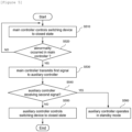
- FIG. 5 is an operational flowchart of a control method of a power supply control apparatus according to embodiments of the present invention.
- the main controller may control the switching device to a closed state (S510). Accordingly, stored power of the battery can be supplied to the driving device and the driving device may operate using the power supplied from the battery.
- the main controller may determine whether an abnormal state has occurred (S520).
- the abnormal state may include a state in which an abnormal reset of the main controller or a state in which an abnormal shutdown of the main controller occurs.
- the main controller may transmit a predefined first signal to the auxiliary controller (S530).
- the first signal may refer to a signal for requesting emergency power supply.
- the main controller may transmit a predefined second signal to the auxiliary controller.
- the second signal may mean a signal for canceling the emergency power supply request.
- the auxiliary controller may wait for a preset period of time.
- the auxiliary controller may control the switching device to be closed for a predefined period, so that emergency power can be supplied to the driving device (S550).
- the auxiliary controller may operate in a standby mode without outputting a control signal to the switching device (S560).
- the operations of the method according to the embodiments of the present invention may be implemented as a computer-readable program or code on a computer-readable recording medium.
- the computer-readable recording medium includes all types of recording devices in which data readable by a computer system is stored.
- the computer-readable recording medium may be distributed in a network-connected computer system to store and execute computer-readable programs or codes in a distributed manner.
- a block or apparatus corresponds to a method step or feature of a method step.
- aspects described in the context of a method may also represent a feature of a corresponding block or item or a corresponding apparatus.
- Some or all of the method steps may be performed by (or using) a hardware device, such as, for example, a microprocessor, a programmable computer, or an electronic circuit. In some embodiments, one or more of the most important method steps may be performed by such an apparatus.
Landscapes
- Engineering & Computer Science (AREA)
- Power Engineering (AREA)
- Life Sciences & Earth Sciences (AREA)
- Sustainable Development (AREA)
- Sustainable Energy (AREA)
- Transportation (AREA)
- Mechanical Engineering (AREA)
- Business, Economics & Management (AREA)
- Emergency Management (AREA)
- Charge And Discharge Circuits For Batteries Or The Like (AREA)
- Stand-By Power Supply Arrangements (AREA)
- Electric Propulsion And Braking For Vehicles (AREA)
- Direct Current Feeding And Distribution (AREA)
Abstract
Description
- This application claims priority to and the benefit of
Korean Patent Application No.10-2023-0004053 filed in the Korean Intellectual Property Office on January 11, 2023 - The present invention relates to a power supply control apparatus and method, and more particularly, to a power supply control apparatus located in a battery system that supplies power to a driving device and a control method thereof.
- Secondary batteries, capable of recharging and reuse may be used as an energy source for small devices such as mobile phones, tablet PCs, and vacuum cleaners and may also be used as energy source for a medium-to-large devices, such as automobiles, and an energy storage system (ESS) for smart grids.
- Secondary batteries may be used in the form of an assembly such as a battery module in which a plurality of battery cells are connected in series or parallel, or a battery pack in which a plurality of battery modules are connected in series or parallel, depending on the requirements of the system. In the case of medium-to-large devices such as electric vehicles, a high-capacity battery system with multiple battery packs connected in parallel may be applied to meet the required capacity of a corresponding device.
- Generally, a battery system applied to a device including a driving unit, such as an electric vehicle, includes a switching device disposed on a power supply path between the battery and the driving unit and a controller that controls the switching device. Here, through controlling the switching device, the stored power of the battery can be supplied or blocked to the driving unit.
- In a process of driving the device equipped with this general battery system, if an unexpected abnormal condition (for example, abnormal reset or shutdown) occurs in the controller, power supply to the driving unit may be cut off, thereby causing the driving unit to suddenly stop and resulting in a safety accident.
- To solve this problem, a solution is needed that can maintain power supply by the battery for a certain period of time so that the device can be stably stopped when an abnormal condition occurs in the controller of the switching unit.
- To obviate one or more problems of the related art, embodiments of the present disclosure provide a power supply control apparatus located in a battery system that supplies power to a driving device.
- To obviate one or more problems of the related art, embodiments of the present disclosure also provide a control method for the power supply control apparatus.
- In order to achieve the objective of the present disclosure, a power supply control apparatus, located in a battery system which supplies power to a driving device, may include a switching device disposed on a power supply path between the battery and the driving device to electrically connect or disconnect the battery and the driving device; a main controller configured to control whether the battery should supply power to the driving device or not by controlling the switching device; and an auxiliary controller configured to control the switching device instead of the main controller in the instance that an abnormality occurs in the main controller.
- The main controller may further be configured to transmit a first signal for requesting emergency power supply to the auxiliary controller in the instance that an abnormal condition occurs in the main controller.
- The main controller may further be configured to output the first signal in the instance that an abnormal reset or shutdown occurs.
- The main controller may further be configured to transmit a second signal for canceling the request for emergency power supply to the auxiliary controller in the instance that the abnormal state is resolved after the first signal is transmitted.
- The auxiliary controller may further be configured to, upon receiving the first signal, control the switching device to a closed state for a predefined period to supply emergency power to the driving device.
- The auxiliary controller may further be configured to control the switching device to be in a closed state for a predefined period so that the auxiliary controller provides emergency power to the driving device in the instance that a signal canceling the request for emergency power supply is not received from the main controller within a preset period of time after the first signal is received.
- The auxiliary controller may further be configured to operate in standby mode without outputting a control signal to the switching device in the instance that a signal canceling the request for emergency power supply is received from the main controller within a preset period of time after the first signal is received.
- The auxiliary controller may further be configured to control the switching device to be in a closed state until the driving device is normally stopped in the instance that an abnormal condition occurs in the main controller while the driving device is operating.
- According to another embodiment of the present disclosure, a control method of a power supply control apparatus, including a switching device disposed on a power supply path between a battery and a driving device, a main controller for controlling the switching device, and an auxiliary controller, may include controlling, by the main controller, the switching device so that output power of the battery is supplied to the driving device; and controlling, by the auxiliary controller, the switching device instead of the main controller in the instance that an abnormality occurs in the main controller while the driving device is operating.
- The method may further include transmitting, by the main controller, a first signal for requesting emergency power supply to the auxiliary controller in the instance that an abnormal condition occurs in the main controller.
- The transmitting, by the main controller, the first signal for requesting emergency power supply to the auxiliary controller may include outputting the first signal in the instance that an abnormal reset or shutdown occurs.
- The method may further include transmitting, by the main controller, a second signal for canceling the request for emergency power supply to the auxiliary controller in the instance that the abnormal state is resolved after the first signal is transmitted.
- The controlling, by the auxiliary controller, the switching device may include, upon receiving the first signal, controlling the switching device to a closed state for a predefined period to supply emergency power to the driving device.
- The controlling, by the auxiliary controller, the switching device may include controlling the switching device to be in a closed state for a predefined period so that the auxiliary controller provides emergency power to the driving device in the instance that a signal canceling the request for emergency power supply is not received from the main controller within a preset period of time after the first signal is received.
- The controlling, by the auxiliary controller, the switching device may include the auxiliary controller operating in standby mode without outputting a control signal to the switching device in the instance that a signal canceling the request for emergency power supply is received from the main controller within a preset period of time after the first signal is received.
- The controlling, by the auxiliary controller, the switching device may include controlling the switching device to be in a closed state until the driving device is normally stopped in the instance that an abnormal condition occurs in the main controller while the driving device is operating.
- According to embodiments of the present invention as described above, even if an unexpected abnormal condition occurs in a main controller that controls a switching device, power supply can be maintained until the driving device is safely stopped, thereby improving safety of a device to which the battery system is applied.
-
-
FIG. 1 is a block diagram for explaining a general power supply control device. -
FIG. 2 is a block diagram for explaining a power supply control apparatus according to embodiments of the present invention. -
FIG. 3 is a block diagram for explaining a power supply control apparatus according to embodiments of the present invention. -
FIG. 4 is an operational flowchart of the control method of a power supply control apparatus according to the present invention. -
FIG. 5 is an operational flowchart of a control method of a power supply control apparatus according to embodiments of the present invention. -
- 100:
- Battery system
- 110:
- battery
- 120:
- power supply control apparatus
- 121:
- switching device
- 122:
- main controller
- 123:
- auxiliary controller
- 200:
- driving device
- The present invention may be modified in various forms and have various embodiments, and specific embodiments thereof are shown by way of example in the drawings and will be described in detail below. It should be understood, however, that there is no intent to limit the present invention to the specific embodiments, but on the contrary, the present invention is to cover all modifications, equivalents, and alternatives falling within the spirit and technical scope of the present invention. Like reference numerals refer to like elements throughout the description of the figures.
- It will be understood that, although the terms such as first, second, A, B, and the like may be used herein to describe various elements, these elements should not be limited by these terms. These terms are only used to distinguish one element from another. For example, a first element could be termed a second element, and, similarly, a second element could be termed a first element, without departing from the scope of the present invention. As used herein, the term "and/or" includes combinations of a plurality of associated listed items or any of the plurality of associated listed items.
- It will be understood that when an element is referred to as being "coupled" or "connected" to another element, it can be directly coupled or connected to the other element or an intervening element may be present. In contrast, when an element is referred to as being "directly coupled" or "directly connected" to another element, there is no intervening element present.
- The terms used herein is for the purpose of describing specific embodiments only and are not intended to limit the present invention. As used herein, the singular forms "a", "an" and "the" are intended to include the plural forms as well, unless the context clearly indicates otherwise. It will be further understood that the terms "comprises", "comprising", "includes", "including" and/or "having", when used herein, specify the presence of stated features, integers, steps, operations, constitutional elements, components and/or combinations thereof, but do not preclude the presence or addition of one or more other features, integers, steps, operations, constitutional elements, components, and/or combinations thereof.
- Unless otherwise defined, all terms used herein, including technical and scientific terms, have the same meanings as commonly understood by one skilled in the art to which the present invention belongs. It will be further understood that terms, such as those defined in commonly used dictionaries, should be interpreted as having meanings that are consistent with their meanings in the context of the relevant art and will not be interpreted in an idealized or overly formal sense unless expressly so defined herein.
- Some terms used herein are defined as follows.
- A battery cell is a minimum unit that serves to store power and a battery module refers to an assembly in which a plurality of battery cells are electrically connected.
- A battery pack or battery rack refers to a system of a single structure which is assembled by electrically connecting module units, set by a battery manufacturer, and can be monitored and controlled by a battery management apparatus/system (BMS). A battery pack or battery rack may include several battery modules and a battery protection unit or any other protection device.
- A battery bank refers to a group of large-scale battery rack systems configured by connecting a plurality of racks in parallel. A bank BMS for a battery bank may monitor and control rack BMSs, each of which manages a battery rack.
- A battery assembly may include a plurality of electrically connected battery cells, and refers to an assembly that functions as a power supply source by being applied to a specific system or device. Here, the battery assembly may mean a battery module, a battery pack, a battery rack, or a battery bank, but the scope of the present invention is not limited to these entities.
-
FIG. 1 is a block diagram for explaining a general power supply control device. - More specifically,
FIG. 1 shows a battery system applied to a device (e.g., electric vehicle, etc.) including a drivingunit 40. - Referring to
FIG. 1 , a typical battery system may include abattery 10, aswitching device 20, and acontrol unit 30. - The switching
device 20 is disposed on the power supply path between thebattery 10 and the drivingunit 40 and is configured to electrically connect or disconnect thebattery 10 and the drivingunit 40. Here, the switchingdevice 20 may be a Metal Oxide Semiconductor Field Effect Transistor (MOSFET) provided at an output terminal of thebattery 10. - The
control unit 30 may control whether to supply power by thebattery 10 by controlling theswitching device 20 to be in a closed state or an open state. Specifically, thecontrol unit 30 controls theswitching device 20 to be in a closed state so that the stored power of thebattery 10 is supplied to the drivingunit 40 and the drivingunit 40 can be driven by the supplied power, or controls theswitching device 20 to be in an open state so that the power supplied from thebattery 10 can be blocked. Here, thecontrol unit 30 may be a micro controller unit (MCU) included in a battery management system (BMS). - According to this general battery system, when an unexpected abnormal state (for example, abnormal reset or shutdown) occurs in the
control unit 30 while the drivingunit 40 is driven by the power supplied from thebattery 10, the power supply to the drivingunit 40 may be cut off, causing the drivingunit 40 to suddenly stop, which may cause a safety accident. - The present invention is developed to solve this problem, and relates to a power supply control apparatus and its control method that can maintain power supply by the battery for a certain period of time so that the electric vehicle can stop stably even if an abnormal condition occurs in the control unit of the switching device.
- Hereinafter, preferred embodiments according to the present invention will be described in detail with reference to the attached drawings.
-
FIG. 2 is a block diagram for explaining a power supply control apparatus according to embodiments of the present invention. In more detail,FIG. 2 shows thebattery system 100 applied to a device including adriving device 200. - The
battery system 100 according to embodiments of the present invention may be located in a device including thedriving device 200 and may supply power to thedriving device 200. Here, the device including a driving device may refer to an object driven through electrical energy, such as an electric car, a hybrid car, an electric bike, or an electric bicycle, and the driving device may refer to an object driven through electrical energy. - Referring to
FIG. 2 , thebattery system 100 may include abattery 110 and a powersupply control apparatus 120. - In the present specification, the
battery 110 may refer to a battery cell or battery assembly. In other words, thebattery 110 may mean one or more battery cells, a battery module, a battery pack, a battery rack, or a battery bank. - The power
supply control apparatus 120 may be disposed on a power supply path between thebattery 110 and thedriving device 200 and is a device that may electrically connect or disconnect thebattery 110 and thedriving device 200. Here, the powersupply control apparatus 120 may include a switching device that may be opened and closed by a control signal and one or more controllers that may control the switching device. - The controller included in the power
supply control apparatus 120 may control the switching device to be in a closed state or an open state, thereby connecting or blocking the power supply path between thebattery 110 and thedriving device 200. Specifically, the controller may control the switching device to be in a closed state so that the stored power of thebattery 110 is supplied to thedriving device 200 and thus, the drivingdevice 200 can be driven using the supplied power, or may control the switching device to be in an open state so that the power supplied from thebattery 110 is cut off. - The controllers included in the power
supply control apparatus 120 may include a main controller and an auxiliary controller. - The main controller may refer to a main control unit that controls the switching device included in the power
supply control apparatus 120. In addition, the auxiliary controller may refer to a sub-control unit that controls the switching device included in the powersupply control apparatus 120 in place of the main controller in the instance that an abnormality occurs in the main controller. - When the battery system operates in a power supply mode, the main controller may control the switching device to be closed so that the stored power of the
battery 110 is supplied to thedriving device 200. If an abnormal condition occurs in the main controller while thedriving device 200 is being driven using power supplied from thebattery 100, the auxiliary controller may substitute the main controller and control the switching device. Here, the abnormal state may mean a state in which an abnormal reset or shutdown of the main controller has occurred. -
FIG. 3 is a block diagram for explaining a power supply control apparatus according to embodiments of the present invention. - Referring to
FIG. 3 , thebattery system 100 may include abattery 110 and a powersupply control apparatus 120. - The power
supply control apparatus 120 may include aswitching device 121 that may be opened and closed by a control signal, amain controller 122 and anauxiliary controller 123 that control the switching device. - The
switching device 121 may be disposed on a power supply path between thebattery 110 and thedriving device 200 and may electrically connect or disconnect thebattery 110 and thedriving device 200. - The
switching device 121 may be controlled by control signals from themain controller 122 and theauxiliary controller 123. In other words, when a control signal is transferred from either themain controller 122 or theauxiliary controller 123, theswitching device 121 may be opened or closed according to the transmitted control signal. - The
main controller 122 may refer to a main control unit that controls the switching device included in the powersupply control apparatus 120. Here, the main controller may be a micro controller unit (MCU) included in a battery management system (BMS). - The
auxiliary controller 123 may refer to a sub- control unit that replaces themain controller 122 and controls theswitching device 121 when an abnormality occurs in themain controller 122. Here, the auxiliary controller may be implemented as a separate integrated circuit (IC) that is separate from the MCU of the battery management system (BMS). - In the following, the operation of the power supply control apparatus according to embodiments of the present invention will be described.
- When the battery system operates in a power supply mode, the
main controller 122 may control theswitching device 121 to be in a closed state. Accordingly, stored power of thebattery 110 is supplied to thedriving device 200 and thedriving device 200 may be driven using the power supplied from thebattery 100. - While the
driving device 200 being operating, themain controller 122 may determine whether an abnormal state has occurred. Here, themain controller 122 may determine whether an abnormal state has occurred based on state information collected through a state information collection device (not shown) provided in the battery system, or based on an abnormal condition occurrence signal transmitted from a higher-level controller (not shown). According to embodiments, the abnormal state may include a state in which an abnormal reset of the main controller or a state in which an abnormal shutdown of the main controller occurs. - When an abnormal condition occurs in the
main controller 122, themain controller 122 may transmit a predefined first signal to theauxiliary controller 123. Here, the first signal may refer to a signal for requesting emergency power supply. - When receiving the first signal from the
main controller 123, theauxiliary controller 123 may control theswitching device 121 to be closed for a predefined period so that emergency power can be supplied to thedriving device 200. Here, the time period of emergency power supply may be defined as a specific time (e.g., 20 seconds) or as the time until thedriving device 200 is normally stopped. Here, theauxiliary controller 123 may check whether thedriving device 200 is stopped through connection with the upper controller or through connection with a controller of thedriving device 200. - In an embodiment of the present invention, in the instance that the abnormal state is cleared after the
main controller 122 transmits the first signal to theauxiliary controller 123, themain controller 122 may send a predefined second signal to theauxiliary controller 123. Here, the second signal may mean a signal for canceling the emergency power supply request. - In this embodiment, when receiving the first signal from the
main controller 123, theauxiliary controller 123 may wait for a preset period of time without immediately controlling theswitching device 121 to a closed state. Here, in the instance that the second signal is not transmitted from themain controller 123 within a predetermined period of time, theauxiliary controller 123 may control theswitching device 121 to be in a closed state for a predefined period and emergency power can be supplied to thedriving device 200. - Meanwhile, when the second signal is transmitted from the
main controller 123 within a preset period of time, theauxiliary controller 123 may operate in standby mode without outputting a control signal to theswitching device 121. - In other words, when an unexpected abnormal condition occurs in the
main controller 122, themain controller 122 may notify theauxiliary controller 123 that it is in a dangerous state requiring emergency power supply. In the instance that theauxiliary controller 123 is not notified of the removal of the dangerous state within a certain period of time, theauxiliary controller 123 may control the switching device to provide temporary power supply to the driving device until the driving device is safely stopped. -
FIG. 4 is an operational flowchart of the control method of a power supply control apparatus according to the present invention. - The power supply control apparatus may include a switching device disposed on a power supply path between the battery and the driving device, a main controller that controls the switching device, and an auxiliary controller.
- When the battery system operates in a power supply mode, the main controller may control the switching device to be closed so that stored power of the battery can be supplied to the driving device (S410). Accordingly, the stored power of the battery is supplied to the driving device, and the driving device may be driven using the power supplied from the battery.
- While the driving device is being operating, the main controller may determine whether an abnormal state has occurred (S420). Here, the main controller may determine whether an abnormal state has occurred based on state information collected through a state information collection device (not shown) provided in the battery system, or based on an abnormal condition occurrence signal transmitted from a higher-level controller (not shown).
- If an abnormal condition has occurred in the main controller (YES in S420), the auxiliary controller may substitute the main controller and control the switching device (S430).
-
FIG. 5 is an operational flowchart of a control method of a power supply control apparatus according to embodiments of the present invention. - When the battery system operates in a power supply mode, the main controller may control the switching device to a closed state (S510). Accordingly, stored power of the battery can be supplied to the driving device and the driving device may operate using the power supplied from the battery.
- While the driving device is being operating, the main controller may determine whether an abnormal state has occurred (S520). According to embodiments, the abnormal state may include a state in which an abnormal reset of the main controller or a state in which an abnormal shutdown of the main controller occurs.
- If an abnormal condition occurs in the main controller (YES in S520), the main controller may transmit a predefined first signal to the auxiliary controller (S530). Here, the first signal may refer to a signal for requesting emergency power supply.
- If the abnormal state is resolved after the main controller transmits the first signal to the auxiliary controller, the main controller may transmit a predefined second signal to the auxiliary controller. Here, the second signal may mean a signal for canceling the emergency power supply request.
- When a first signal is received from the main controller, the auxiliary controller may wait for a preset period of time.
- If the second signal is not transmitted from the main controller within a preset period of time (NO in S540), the auxiliary controller may control the switching device to be closed for a predefined period, so that emergency power can be supplied to the driving device (S550).
- If the second signal is transmitted from the main controller within a preset period of time (YES in S540), the auxiliary controller may operate in a standby mode without outputting a control signal to the switching device (S560).
- The operations of the method according to the embodiments of the present invention may be implemented as a computer-readable program or code on a computer-readable recording medium. The computer-readable recording medium includes all types of recording devices in which data readable by a computer system is stored. In addition, the computer-readable recording medium may be distributed in a network-connected computer system to store and execute computer-readable programs or codes in a distributed manner.
- Although some aspects of the invention have been described in the context of the apparatus, it may also represent a description according to a corresponding method, wherein a block or apparatus corresponds to a method step or feature of a method step. Similarly, aspects described in the context of a method may also represent a feature of a corresponding block or item or a corresponding apparatus. Some or all of the method steps may be performed by (or using) a hardware device, such as, for example, a microprocessor, a programmable computer, or an electronic circuit. In some embodiments, one or more of the most important method steps may be performed by such an apparatus.
- In the forgoing, the present invention has been described with reference to the exemplary embodiment of the present invention, but those skilled in the art may appreciate that the present invention may be variously corrected and changed within the range without departing from the spirit and the area of the present invention described in the appending claims.
Claims (16)
- A power supply control apparatus located in a battery system which supplies power to a driving device, the apparatus comprising:a switching device disposed on a power supply path between the battery and the driving device to electrically connect or disconnect the battery and the driving device;a main controller configured to control whether the battery should supply power to the driving device or not by controlling the switching device; andan auxiliary controller configured to control the switching device instead of the main controller in the instance that an abnormality occurs in the main controller.
- The apparatus of claim 1, wherein the main controller is further configured to transmit a first signal for requesting emergency power supply to the auxiliary controller in the instance that an abnormal condition occurs in the main controller.
- The apparatus of claim 2, wherein the main controller is further configured to output the first signal in the instance that an abnormal reset or shutdown occurs.
- The apparatus of claim 2, wherein the main controller is further configured to transmit a second signal for canceling the request for emergency power supply to the auxiliary controller in the instance that the abnormal condition is resolved after the first signal is transmitted.
- The apparatus of claim 2, wherein the auxiliary controller is further configured to, upon receiving the first signal, control the switching device to a closed state for a predefined period to supply emergency power to the driving device.
- The apparatus of claim 2, wherein the auxiliary controller is further configured to control the switching device to be in a closed state for a predefined period so that the auxiliary controller provides emergency power to the driving device in the instance that a signal canceling the request for emergency power supply is not received from the main controller within a preset period of time after the first signal is received.
- The apparatus of claim 2, wherein the auxiliary controller is further configured to operate in standby mode without outputting a control signal to the switching device in the instance that a signal canceling the request for emergency power supply is received from the main controller within a preset period of time after the first signal is received.
- The apparatus of claim 1, wherein the auxiliary controller is further configured to control the switching device to be in a closed state until the driving device is normally stopped in the instance that an abnormal condition occurs in the main controller while the driving device is operating.
- A control method of a power supply control apparatus including a switching device disposed on a power supply path between a battery and a driving device, a main controller for controlling the switching device, and an auxiliary controller, the method comprising:controlling, by the main controller, the switching device so that output power of the battery is supplied to the driving device; andcontrolling, by the auxiliary controller, the switching device instead of the main controller in the instance that an abnormality occurs in the main controller while the driving device is operating.
- The method of claim 9, further comprising transmitting, by the main controller, a first signal for requesting emergency power supply to the auxiliary controller in the instance that an abnormal condition occurs in the main controller.
- The method of claim 10, wherein the transmitting, by the main controller, the first signal for requesting emergency power supply to the auxiliary controller includes outputting the first signal in the instance that an abnormal reset or shutdown occurs.
- The method of claim 10, further comprising transmitting, by the main controller, a second signal for canceling the request for emergency power supply to the auxiliary controller in the instance that the abnormal condition is resolved after the first signal is transmitted.
- The method of claim 10, wherein the controlling, by the auxiliary controller, the switching device includes, upon receiving the first signal, controlling the switching device to a closed state for a predefined period to supply emergency power to the driving device.
- The method of claim 10, wherein the controlling, by the auxiliary controller, the switching device includes controlling the switching device to be in a closed state for a predefined period so that the auxiliary controller provides emergency power to the driving device in the instance that a signal canceling the request for emergency power supply is not received from the main controller within a preset period of time after the first signal is received.
- The method of claim 10, wherein the controlling, by the auxiliary controller, the switching device includes the auxiliary controller operating in standby mode without outputting a control signal to the switching device in the instance that a signal canceling the request for emergency power supply is received from the main controller within a preset period of time after the first signal is received.
- The method of claim 9, wherein the controlling, by the auxiliary controller, the switching device includes controlling the switching device to be in a closed state until the driving device is normally stopped in the instance that an abnormal condition occurs in the main controller while the driving device is operating.
Applications Claiming Priority (2)
| Application Number | Priority Date | Filing Date | Title |
|---|---|---|---|
| KR1020230004053A KR20240111995A (en) | 2023-01-11 | 2023-01-11 | Power supply control device and method |
| PCT/KR2023/017019 WO2024150905A1 (en) | 2023-01-11 | 2023-10-30 | Power supply control device and method for controlling same |
Publications (2)
| Publication Number | Publication Date |
|---|---|
| EP4503375A1 true EP4503375A1 (en) | 2025-02-05 |
| EP4503375A4 EP4503375A4 (en) | 2025-10-08 |
Family
ID=91897206
Family Applications (1)
| Application Number | Title | Priority Date | Filing Date |
|---|---|---|---|
| EP23916388.4A Pending EP4503375A4 (en) | 2023-01-11 | 2023-10-30 | POWER SUPPLY CONTROL DEVICE AND METHOD FOR CONTROLLING THE SAME |
Country Status (6)
| Country | Link |
|---|---|
| US (1) | US12609544B2 (en) |
| EP (1) | EP4503375A4 (en) |
| JP (1) | JP2025515351A (en) |
| KR (1) | KR20240111995A (en) |
| CN (1) | CN119111027A (en) |
| WO (1) | WO2024150905A1 (en) |
Family Cites Families (15)
| Publication number | Priority date | Publication date | Assignee | Title |
|---|---|---|---|---|
| JP2008206288A (en) * | 2007-02-20 | 2008-09-04 | Toyota Motor Corp | Vehicle control device, vehicle control method, and vehicle control program |
| JP5469625B2 (en) * | 2011-03-01 | 2014-04-16 | 株式会社日立製作所 | Battery system |
| KR101855092B1 (en) | 2012-01-18 | 2018-05-08 | 에스케이이노베이션 주식회사 | Relay control signal independent monitoring apparatus and method |
| JP5598499B2 (en) * | 2012-06-15 | 2014-10-01 | 株式会社デンソー | Battery monitoring device |
| KR101641435B1 (en) * | 2014-12-16 | 2016-07-20 | 중소기업은행 | Battery management system and electric vehicles equipped with the same |
| KR102273770B1 (en) | 2016-07-19 | 2021-07-06 | 삼성에스디아이 주식회사 | battery system |
| DE112019000335B4 (en) | 2018-02-15 | 2025-10-02 | Hitachi Astemo, Ltd. | Battery management unit |
| JP2019161991A (en) | 2018-03-16 | 2019-09-19 | 株式会社デンソー | Electronic control device |
| KR102390394B1 (en) * | 2018-05-15 | 2022-04-22 | 주식회사 엘지에너지솔루션 | Apparatus and method for controlling main battery and sub battery |
| KR102452596B1 (en) | 2018-06-01 | 2022-10-06 | 주식회사 엘지에너지솔루션 | Apparatus and method for diagnosing MOSFET |
| KR102690979B1 (en) | 2018-11-05 | 2024-07-31 | 주식회사 엘지에너지솔루션 | Apparatus and method for diagnosing a power switch |
| KR20220130516A (en) | 2021-03-18 | 2022-09-27 | 주식회사 엘지에너지솔루션 | Relay control apparatus, battery pack and electric vehicle |
| KR20220157181A (en) | 2021-05-20 | 2022-11-29 | 삼성에스디아이 주식회사 | Battery protection apparatus and battery system including the same |
| CN115697753B (en) | 2021-05-21 | 2025-12-05 | 深圳引望智能技术有限公司 | Power distribution equipment, vehicles and troubleshooting methods |
| KR20230004053A (en) | 2021-06-30 | 2023-01-06 | 엘지전자 주식회사 | Interface and Laundry Treatment Apparatus having the Same |
-
2023
- 2023-01-11 KR KR1020230004053A patent/KR20240111995A/en active Pending
- 2023-10-30 WO PCT/KR2023/017019 patent/WO2024150905A1/en not_active Ceased
- 2023-10-30 CN CN202380036756.9A patent/CN119111027A/en active Pending
- 2023-10-30 JP JP2024563550A patent/JP2025515351A/en active Pending
- 2023-10-30 US US18/859,661 patent/US12609544B2/en active Active
- 2023-10-30 EP EP23916388.4A patent/EP4503375A4/en active Pending
Also Published As
| Publication number | Publication date |
|---|---|
| WO2024150905A1 (en) | 2024-07-18 |
| US20250286392A1 (en) | 2025-09-11 |
| EP4503375A4 (en) | 2025-10-08 |
| KR20240111995A (en) | 2024-07-18 |
| US12609544B2 (en) | 2026-04-21 |
| JP2025515351A (en) | 2025-05-14 |
| CN119111027A (en) | 2024-12-10 |
Similar Documents
| Publication | Publication Date | Title |
|---|---|---|
| KR102910661B1 (en) | Battery protection apparatus and battery system including the same | |
| EP3576241B1 (en) | Battery system | |
| KR101501786B1 (en) | Battery module and module pack | |
| US8405357B2 (en) | Battery unit, battery system, electronic device, charging control method of battery, and discharging control method of battery | |
| EP1462299B1 (en) | Battery power source apparatus of electric car and its method of operation | |
| CN106882051B (en) | Fuse is used for the transduction feature of the fuse element of detection before disconnecting | |
| CN101517852B (en) | Discharger and discharge control method | |
| EP4531226A1 (en) | Energy storage control system | |
| CN104871387B (en) | For the security concept being integrated into battery in inverter | |
| EP3054553B1 (en) | Cell monitoring device, method, and computer program | |
| CN113258631A (en) | Energy storage system protection system | |
| EP3734920A1 (en) | Inter-bms communication system and method | |
| JP5361594B2 (en) | Lithium ion secondary battery system and power supply method to management device | |
| EP3863141A1 (en) | Battery system | |
| EP3680955A1 (en) | Battery system | |
| EP4620728A1 (en) | Battery system and operating method of battery system | |
| US12609544B2 (en) | Power supply control device and method for controlling same | |
| EP3840102B1 (en) | Bms recognition system and method | |
| CN119032485A (en) | Energy storage systems and methods using second-life electric vehicle batteries | |
| US20250286157A1 (en) | Battery Management System Having Hierarchical Structure and Method for Operating Same | |
| KR20180112484A (en) | Battery management apparatus and method having added redundant battery | |
| JP2000014020A (en) | Safety device, battery pack and electronic equipment | |
| KR20250122646A (en) | Battery system for protecting battery and operating method thereof | |
| KR20260033425A (en) | Battery system and operating method thereof | |
| CN121336340A (en) | Battery control device and method |
Legal Events
| Date | Code | Title | Description |
|---|---|---|---|
| STAA | Information on the status of an ep patent application or granted ep patent |
Free format text: STATUS: THE INTERNATIONAL PUBLICATION HAS BEEN MADE |
|
| PUAI | Public reference made under article 153(3) epc to a published international application that has entered the european phase |
Free format text: ORIGINAL CODE: 0009012 |
|
| STAA | Information on the status of an ep patent application or granted ep patent |
Free format text: STATUS: REQUEST FOR EXAMINATION WAS MADE |
|
| 17P | Request for examination filed |
Effective date: 20241030 |
|
| AK | Designated contracting states |
Kind code of ref document: A1 Designated state(s): AL AT BE BG CH CY CZ DE DK EE ES FI FR GB GR HR HU IE IS IT LI LT LU LV MC ME MK MT NL NO PL PT RO RS SE SI SK SM TR |
|
| A4 | Supplementary search report drawn up and despatched |
Effective date: 20250909 |
|
| RIC1 | Information provided on ipc code assigned before grant |
Ipc: H02J 7/00 20060101AFI20250903BHEP Ipc: B60L 3/00 20190101ALI20250903BHEP Ipc: H02J 9/06 20060101ALI20250903BHEP Ipc: B60L 3/04 20060101ALI20250903BHEP |
|
| STAA | Information on the status of an ep patent application or granted ep patent |
Free format text: STATUS: EXAMINATION IS IN PROGRESS |
|
| 17Q | First examination report despatched |
Effective date: 20260211 |
|
| DAV | Request for validation of the european patent (deleted) | ||
| DAX | Request for extension of the european patent (deleted) |