EP4503354A1 - Clamping device for a withdrawable low-voltage circuit breaker unit - Google Patents
Clamping device for a withdrawable low-voltage circuit breaker unit Download PDFInfo
- Publication number
- EP4503354A1 EP4503354A1 EP23189362.9A EP23189362A EP4503354A1 EP 4503354 A1 EP4503354 A1 EP 4503354A1 EP 23189362 A EP23189362 A EP 23189362A EP 4503354 A1 EP4503354 A1 EP 4503354A1
- Authority
- EP
- European Patent Office
- Prior art keywords
- clamping
- clamping device
- fingers
- seat
- pair
- Prior art date
- Legal status (The legal status is an assumption and is not a legal conclusion. Google has not performed a legal analysis and makes no representation as to the accuracy of the status listed.)
- Granted
Links
Images





Classifications
-
- H—ELECTRICITY
- H02—GENERATION; CONVERSION OR DISTRIBUTION OF ELECTRIC POWER
- H02B—BOARDS, SUBSTATIONS OR SWITCHING ARRANGEMENTS FOR THE SUPPLY OR DISTRIBUTION OF ELECTRIC POWER
- H02B11/00—Switchgear having carriage withdrawable for isolation
- H02B11/02—Details
- H02B11/04—Isolating-contacts, e.g. mountings or shieldings
-
- H—ELECTRICITY
- H01—ELECTRIC ELEMENTS
- H01H—ELECTRIC SWITCHES; RELAYS; SELECTORS; EMERGENCY PROTECTIVE DEVICES
- H01H9/00—Details of switching devices, not covered by groups H01H1/00 - H01H7/00
- H01H9/20—Interlocking, locking, or latching mechanisms
- H01H9/26—Interlocking, locking, or latching mechanisms for interlocking two or more switches
-
- H—ELECTRICITY
- H01—ELECTRIC ELEMENTS
- H01H—ELECTRIC SWITCHES; RELAYS; SELECTORS; EMERGENCY PROTECTIVE DEVICES
- H01H71/00—Details of the protective switches or relays covered by groups H01H73/00 - H01H83/00
- H01H71/08—Terminals; Connections
-
- H—ELECTRICITY
- H01—ELECTRIC ELEMENTS
- H01H—ELECTRIC SWITCHES; RELAYS; SELECTORS; EMERGENCY PROTECTIVE DEVICES
- H01H71/00—Details of the protective switches or relays covered by groups H01H73/00 - H01H83/00
- H01H71/10—Operating or release mechanisms
-
- H—ELECTRICITY
- H01—ELECTRIC ELEMENTS
- H01R—ELECTRICALLY-CONDUCTIVE CONNECTIONS; STRUCTURAL ASSOCIATIONS OF A PLURALITY OF MUTUALLY-INSULATED ELECTRICAL CONNECTING ELEMENTS; COUPLING DEVICES; CURRENT COLLECTORS
- H01R13/00—Details of coupling devices of the kinds covered by groups H01R12/70 or H01R24/00 - H01R33/00
- H01R13/02—Contact members
- H01R13/10—Sockets for co-operation with pins or blades
- H01R13/11—Resilient sockets
- H01R13/113—Resilient sockets co-operating with pins or blades having a rectangular transverse section
-
- H—ELECTRICITY
- H01—ELECTRIC ELEMENTS
- H01R—ELECTRICALLY-CONDUCTIVE CONNECTIONS; STRUCTURAL ASSOCIATIONS OF A PLURALITY OF MUTUALLY-INSULATED ELECTRICAL CONNECTING ELEMENTS; COUPLING DEVICES; CURRENT COLLECTORS
- H01R13/00—Details of coupling devices of the kinds covered by groups H01R12/70 or H01R24/00 - H01R33/00
- H01R13/02—Contact members
- H01R13/193—Means for increasing contact pressure at the end of engagement of coupling part, e.g. zero insertion force or no friction
-
- H—ELECTRICITY
- H02—GENERATION; CONVERSION OR DISTRIBUTION OF ELECTRIC POWER
- H02B—BOARDS, SUBSTATIONS OR SWITCHING ARRANGEMENTS FOR THE SUPPLY OR DISTRIBUTION OF ELECTRIC POWER
- H02B11/00—Switchgear having carriage withdrawable for isolation
- H02B11/12—Switchgear having carriage withdrawable for isolation with isolation by horizontal withdrawal
-
- H—ELECTRICITY
- H01—ELECTRIC ELEMENTS
- H01H—ELECTRIC SWITCHES; RELAYS; SELECTORS; EMERGENCY PROTECTIVE DEVICES
- H01H9/00—Details of switching devices, not covered by groups H01H1/00 - H01H7/00
- H01H9/20—Interlocking, locking, or latching mechanisms
- H01H9/26—Interlocking, locking, or latching mechanisms for interlocking two or more switches
- H01H2009/265—Interlocking, locking, or latching mechanisms for interlocking two or more switches with interlocking of more than two switches
-
- H—ELECTRICITY
- H01—ELECTRIC ELEMENTS
- H01H—ELECTRIC SWITCHES; RELAYS; SELECTORS; EMERGENCY PROTECTIVE DEVICES
- H01H2211/00—Spacers
-
- H—ELECTRICITY
- H01—ELECTRIC ELEMENTS
- H01R—ELECTRICALLY-CONDUCTIVE CONNECTIONS; STRUCTURAL ASSOCIATIONS OF A PLURALITY OF MUTUALLY-INSULATED ELECTRICAL CONNECTING ELEMENTS; COUPLING DEVICES; CURRENT COLLECTORS
- H01R13/00—Details of coupling devices of the kinds covered by groups H01R12/70 or H01R24/00 - H01R33/00
- H01R13/02—Contact members
- H01R13/15—Pins, blades or sockets having separate spring member for producing or increasing contact pressure
- H01R13/18—Pins, blades or sockets having separate spring member for producing or increasing contact pressure with the spring member surrounding the socket
Definitions
- the present invention generally falls within the technical field of low-voltage circuit breakers, particularly of withdrawable low-voltage circuit breakers. More in particular, the present invention relates to a slide-in clamping device for removably connecting a first electrical terminal of a withdrawable low-voltage circuit breaker to a corresponding second electrical terminal of a respective stationary base in a withdrawable low-voltage circuit breaker unit.
- Low-voltage circuit breakers are commonly used in low-voltage power distribution systems, for protecting electrical circuits and electrical equipment connected thereto from fault conditions, such as short-circuits, overloads, etc.
- withdrawable low-voltage circuit breaker units have become very popular due to the possibility of replacement without having to re-wire them each time, thus reducing replacement time and costs.
- a withdrawable low-voltage circuit breaker unit is essentially formed of two elements, namely a stationary base, which is fixed to a suitable support structure, for example a case or frame, and is permanently electrically connected to a corresponding electrical circuit, and a withdrawable part, the actual circuit breaker, which can be withdrawn from and re-installed onto the stationary base when required, for example for maintenance or replacement.
- the base comprises one or more stationary electrical terminals and the circuit breaker comprises one or more corresponding withdrawable electrical terminals.
- slide-in clamping devices having a first clamping seat for one or more of said stationary electrical terminals or, respectively, said withdrawable electrical terminals, at least partially laterally delimited by one or more pairs of first clamping fingers facing each other and comprising a respective slide-in opening, and a second clamping seat for corresponding one or more of said withdrawable electrical terminals or, respectively, said stationary electrical terminals, at least partially laterally delimited by one or more pairs of second clamping fingers facing each other and comprising a respective slide-in opening facing oppositely relative to the slide-in opening of the first clamping seat.
- the clamping seats are electrically connected to each other via the respective clamping fingers.
- Bias elastic means act on said pairs of first clamping fingers and second clamping fingers so as to urge the clamping fingers of each pair towards each other in a clamping direction perpendicular to the slide-in directions of the first clamping seat and the second clamping seat, thus maintaining the first clamping seat and the second clamping seat in a clamping condition.
- a fixed spacer member is interposed between the clamping fingers or they are partially constrained in a mounting frame of the clamping device.
- one of the clamping seats of such slide-in clamping devices typically remains always clamped to one of the stationary electrical terminals of the stationary base or, respectively, one of the withdrawable electrical terminals of the withdrawable circuit breaker, whereas the other clamping seat is engaged or disengaged by a corresponding withdrawable electrical terminal of the withdrawable circuit breaker or, respectively, stationary electrical terminal of the stationary base each time the withdrawable circuit breaker has to be connected to or disconnected from its stationary base.
- an object of the present invention to provide a slide-in clamping device for mechanically and electrically connecting electrical terminals of a withdrawable low-voltage breaker unit which allows the force for inserting such electrical terminals into respective clamping seats of the slide-in clamping device to be reduced, while still ensuring a secure and tight connection between clamping fingers of the clamping seats and electrical terminals when the electrical terminals are fully inserted in the respective clamping seats.
- Another object of the present invention is to provide a slide-in clamping device as mentioned above which has a simple construction and can be manufactured at low costs.
- Still another object of the present invention is to provide a slide-in clamping device as mentioned above, whose main features can be easily implemented also in existing slide-in clamping devices.
- a slide-in clamping device for removably connecting a first electrical terminal of a withdrawable low-voltage circuit breaker to a second electrical terminal of a respective stationary base in a withdrawable low-voltage circuit breaker unit, the clamping device comprising:
- the slide-in clamping device of the invention further comprises at least one displaceable spacer assembly having a displaceable spacer member, wherein the displaceable spacer member is displaceable between an active position, in which the displaceable spacer member contacts the first clamping fingers of the at least one pair of first clamping fingers or the second clamping fingers of the at least one pair of second clamping fingers urging them away from each other in the clamping direction, and an inactive position, in which the displaceable spacer member does not apply any significant force to said first clamping fingers or said second clamping fingers.
- the invention proposes to use a displaceable spacer assembly having a displaceable spacer member to selectively apply a force to the clamping fingers of a respective clamping seat which counteracts the clamping force generated by the bias elastic means of the clamping device acting on the same clamping fingers.
- the displaceable spacer member When the displaceable spacer member is in its active position, it spreads the clamping fingers apart from each other to a certain predetermined extent as compared to their position under the sole action of the bias elastic means and without electrical terminal inserted in the corresponding clamping seat. This facilitates the insertion of an electrical terminal into the clamping seat, thus reducing the insertion force required for this purpose and also the friction wear of the clamping fingers and of the electrical terminals resulting from this operation.
- the displaceable spacer member When instead the displaceable spacer member is in its inactive position, it does not act on the clamping fingers, so that they can fully develop their clamping action under the action of the bias elastic means, ensuring a secure and tight clamping connection between clamping seat and electrical terminal inserted therein.
- a displaceable spacer assembly capable of operating as described above may be designed so as to have a simple and robust configuration, involving a minimum number of parts, which allows the slide-in clamping device of the invention to be manufactured easily and at low costs. Moreover, such a displaceable spacer assembly can also be easily designed to fit into known slide-in clamping devices for withdrawable low-voltage circuit breaker units, therefore the present invention is also useful for retrofitting conventional clamping devices already available on the market.
- the at least one displaceable spacer assembly comprises displaceable spacer assembly bias elastic means urging the displaceable spacer member towards its active position.
- bias elastic means it is advantageously possible not only to autonomously keep the displaceable spacer member in the above-mentioned active position, so as to apply the desired spreading force onto the clamping fingers when no electrical terminal is inserted into the clamping seat, but also to autonomously bring the displaceable spacer member from the inactive position back into the active position when an electrical terminal is withdrawn from the clamping seat.
- the at least one displaceable spacer assembly is fully received, preferably removably, in the first or the second clamping seat of the clamping device.
- the displaceable spacer member when the displaceable spacer member is in the active position, i.e., no electrical terminal is inserted in the corresponding clamping seat, the displaceable spacer member is retained within the clamping seat only by means of the respective clamping fingers.
- the displaceable spacer member is displaceable along the slide-in direction of the first clamping seat or the second clamping seat.
- the displaceable spacer member is displaceable by the first electrical terminal or the second electrical terminal upon insertion thereof in the respective clamping seat.
- the displaceable spacer member is in its inactive position.
- the displaceable spacer member is in its active position.
- the displaceable spacer member of the displaceable spacer assembly is configured as a plate.
- the displaceable spacer assembly bias elastic means comprise one or more cantilever springs, one or more compression coil springs, or combinations thereof.
- the resulting displaceable spacer assembly has a simple and robust structure, which nevertheless can be easily adapted to fit into clamping device of different forms and sizes.
- the displaceable spacer assembly bias elastic means are attached to the displaceable spacer member.
- the displaceable spacer assembly thus forms a single-piece component, which can be more easily manipulated inside and outside the clamping device and mounted/removed into/form the same.
- the displaceable spacer member is configured as a plate and the displaceable spacer assembly bias elastic means are or comprise at least one cantilever spring, the latter can be integrally formed with the displaceable spacer member.
- the first clamping fingers and the second clamping fingers comprise respective inner contact protrusions projecting inwardly in the first clamping seat or the second clamping seat, respectively.
- Such inner contact protrusions properly define the contact area between the clamping fingers and the electrical terminal inserted into the corresponding clamping seat, and at the same time may also advantageously function as retainers for the displaceable spacer member so that it does not slip out from the respective clamping seat under the action of the displaceable spacer assembly bias elastic means when the clamping seat is in a rest condition, i.e., no electrical terminal is inserted therein and the displaceable spacer member is in its active position.
- the slide-in directions of the first clamping seat and of the second clamping seat substantially coincide with each other.
- the clamping device of the invention comprises at least one pair of integrally formed clamping members facing each other and at least partially laterally delimiting both the first clamping seat and the second clamping seat, the first clamping fingers of the at least one pair of first clamping fingers being defined by first longitudinal end portions of said clamping members, and the second clamping fingers of said at least one pair of second clamping fingers being defined by second longitudinal end portions of said clamping members.
- the clamping device further comprises a fixed spacer member interposed between the clamping members of said at least one pair of clamping members for maintaining them at a predetermined distance from each other against the action of the bias elastic means of the clamping device.
- the clamping device comprises a plurality of pairs of said clamping members arranged in two rows facing each other and extending parallel to a longitudinal midplane of the clamping device containing the slide-in directions of the first clamping seat and the second clamping seat. More preferably, the two rows of clamping members are symmetrically located relative to said longitudinal midplane.
- This configuration of the clamping device also known in the art as "jaw" configuration, is particularly suitable for connecting bar-like electrical terminals, such as for example busbars, having a square or rectangular cross section.
- the bias elastic means preferably comprise a pair of leaf springs each acting on one of said rows of clamping members at respective longitudinal end portions thereof.
- each leaf spring may be formed as a single piece comprising two opposite contact portions, for contacting the respective row of clamping members at their longitudinal end portions, and a central connecting portion which connects the two contact portions.
- Each contact portion has a comb-like structure comprising a plurality of prongs corresponding to the plurality of pairs of clamping members. In this way, the bias elastic means can apply the biasing force to each clamping finger individually.
- the clamping device comprises at least one pair of clamping members circumferentially arranged about a longitudinal axis defined by the slide-in directions of said first clamping seat and said second clamping seat.
- This configuration also known in the art as "tulip" configuration, of the clamping device is particularly suitable for connecting finger-like electrical terminals having a round cross section
- the bias elastic means preferably comprise a pair of compression rings circumferentially surrounding the at least one pair of clamping members at the longitudinal end portions thereof.
- Each compression ring may be formed, for example, by one or more annular traction coil springs, or by a ring made of a resilient material.
- the at least one pair of clamping members are arranged in the clamping device without the aid of a mounting frame.
- the displaceable spacer assembly bias elastic means, at a side thereof opposite to the displaceable spacer member, preferably abut against the fixed spacer member.
- the displaceable spacer assembly bias elastic means at a side thereof opposite to the displaceable spacer member, may conveniently abut against one of said first and second electrical terminals received in the clamping seat other than the one where the displaceable spacer assembly acts.
- a withdrawable low-voltage circuit breaker unit comprising a withdrawable low-voltage circuit breaker having at least one first electrical terminal, a stationary base having at least one corresponding second electrical terminal, and a slide-in clamping device according to any one of the previous claims which removably connects said first and second electrical terminals to each other.
- the present invention relates to a slide-in clamping device for withdrawable low-voltage circuit breaker units.
- low-voltage it is meant an electrical voltage lower than or equal to about 2500 V.
- a withdrawable low-voltage circuit breaker unit basically comprises a stationary base 302, which is fixed to a suitable supporting structure 3021, such as a case or a frame, and remains permanently electrically wired to a corresponding electrical circuit (not shown), and a withdrawable circuit breaker 301, which can be withdrawn from and mounted again onto the stationary base 302 whenever required, without the need of re-wiring each time the whole unit.
- a suitable supporting structure 3021 such as a case or a frame
- a withdrawable circuit breaker 301 which can be withdrawn from and mounted again onto the stationary base 302 whenever required, without the need of re-wiring each time the whole unit.
- the withdrawable circuit breaker 301 and the stationary base 302 are per se known and their specific configuration is not relevant for the present invention, therefore they are not described in more detail herein.
- the withdrawable circuit breaker 301 comprises one or more electrical terminals 311, in the following also referred to as withdrawable electrical terminals 311, which are only partially visible in Fig. 11b .
- the stationary base 302 comprises one or more electrical terminals 312, in the following also referred to as stationary electrical terminals 312, which are neither visible in Fig. 11a , being in this case covered by respective slide-in clamping devices of the invention, nor in Fig. 11b , because of the point of view of the figure.
- each electrical terminal 311 of the withdrawable circuit breaker 301 is mechanically and electrically connected with a corresponding electrical terminal 312 of the stationary base 302 by means of a respective slide-in clamping device according to the invention.
- FIG. 1 A first preferred embodiment of such a slide-in clamping device is shown in Figs 1-6 and is generally indicated at 100.
- the slide-in clamping device 100 comprises a first clamping seat 110 for receiving one of said withdrawable electrical terminals 311, or, respectively, of said stationary electrical terminals 312, and a second clamping seat 120 for receiving a corresponding one of said stationary electrical terminals 312 or, respectively, of said withdrawable electrical terminals 311.
- the electrical terminals 311, 312 can be inserted into the respective clamping seat 110 or 120 through respective slide-in openings 111, 112 facing oppositely to each other.
- the clamping seats 110, 120 have respective slide-in directions which preferably coincide with each other, defining a common slide-in axis X1-X1 of the clamping device 100.
- each clamping member 130 comprises a first longitudinal end portion defining a clamping finger 131 of the first clamping seat 110, and a second longitudinal end portion defining a clamping finger 132 of the second clamping seat 120.
- the first clamping seat 110 is at least partially laterally delimited by pairs of respective clamping fingers 131 arranged in two rows facing each other and parallel to each other, coinciding with the rows 137, 138 of clamping members 130.
- the second clamping seat 120 is at least partially laterally delimited by pairs of respective clamping fingers 132 arranged in two rows facing each other and parallel to each other, also coinciding with the rows 137, 138 of clamping members 130.
- the clamping seats 110 and 120 have a straight, substantially parallelepiped configuration, open at the respective longitudinal ends and at the respective slide-in openings 111, 112.
- This configuration is particularly suitable for connecting bar-like electrical terminals 311, 312, such as for example busbars, having a square or rectangular cross section, wherein the rows of clamping fingers 131, 132 respectively of the first clamping seat 110 and of the second clamping seat 120 act as straight clamping jaws on the respective electrical terminal 311 or 312.
- each clamping member 130 has a same configuration.
- each clamping member 130 is preferably integrally formed and is preferably configured as a substantially straight bar with generally rectangular or square cross section, whose size may vary along the longitudinal extension of the bar so as to provide the clamping member 130 with a longitudinally variable outer profile.
- each clamping finger 131 of the first camping seat 110 i.e., each first end portion of the clamping members 130
- each clamping finger 132 of the second clamping seat 120 i.e., each second end portion of the clamping members 130
- each inner contact protrusion 133 projecting inwardly in the first clamping seat 110 or, respectively, second clamping seat 120, at which the clamping finger 131 or 132 contacts an electrical terminal 311 or 312 inserted into the corresponding clamping seat 110 or 120.
- the inner contact protrusions 133 may be conveniently configured as solid bulges integrally formed on an inwardly facing surface of the respective clamping finger 131 or 132.
- the inner contact protrusions 133 preferably have a round profile in the direction of longitudinal extension of the respective clamping finger 131 or 132, for facilitating the insertion and withdrawal of the electrical terminals 311, 312 into/from the respective clamping seat 110 or 120.
- Each clamping finger 131 of the first clamping seat 110 and each clamping finger 132 of the second clamping seat 120 preferably also comprises an outer contact protrusion 134, projecting outwardly relative to the respective clamping seat 110 or 120, at which the clamping finger 131 or 132 is contacted by bias elastic means 140 of the clamping device 100, described in more detail below.
- the outer contact protrusions 134 may be conveniently configured as wedge-shaped portions integrally formed on an outwardly facing surface of the respective clamping finger 131 or 132, whose projecting height increases moving towards the tip of the respective clamping finger 131 or 132.
- the outer contact protrusions 134 preferably have a flat profile in the direction of longitudinal extension of the respective clamping finger 131 or 132, preferably terminating with an abutment notch 135 at the tip of the clamping finger 131 or 132.
- each clamping member 130 preferably comprises a transverse groove 136 formed in or defined on a surface thereof facing inwardly with reference to the operating arrangement of the clamping member 130 in the clamping device 100.
- the respective transverse grooves 136 overall define two straight longitudinal rails 139, facing each other, for guiding the insertion of and retaining a fixed spacer member 160 of the clamping device 100, described in more detail below. Only one of said rails 139 is visible in Fig. 2 .
- clamping fingers 131, 132 i.e., the clamping members 130, shall also ensure electrical connection between the clamping seats 110, 120, and thus between the electrical terminals 311, 312 inserted therein, they are made of a material, in particular a metal or metal alloy, having good electrical conductivity, such as for example copper, silver, aluminum, or special metal alloys.
- the clamping device 100 further comprises bias elastic means which provide the required clamping force at the clamping seats 110, 120, by urging opposite clamping fingers 131 or 132, i.e., corresponding longitudinal end portions of respective clamping members 130, of the rows 137, 138 towards each other in a clamping direction which is perpendicular to the slide-in axis X1-X1 of the clamping seats 110, 120 and to the rows 137, 138, and thus coincides with a transverse axis Y-Y of the clamping device 100.
- bias elastic means which provide the required clamping force at the clamping seats 110, 120, by urging opposite clamping fingers 131 or 132, i.e., corresponding longitudinal end portions of respective clamping members 130, of the rows 137, 138 towards each other in a clamping direction which is perpendicular to the slide-in axis X1-X1 of the clamping seats 110, 120 and to the rows 137, 138, and thus coincides with a transverse axis
- the bias elastic means of the clamping device 100 comprise a pair of leaf springs 140, each acting on a respective row 137 or 138 of clamping members 130, at the longitudinal end portions thereof.
- both leaf springs 140 have a same configuration, comprising two opposite contact portions 141, 142, which contact the rows 137, 138 of clamping members 130, and a central connecting portion 143, which connects the contact portions 141, 142.
- the contact portions 141, 142 preferably have a comb-like structure comprising a plurality of prongs 144 corresponding to the plurality clamping members 130 of each row 137, 138 of clamping members 130.
- Each prong 144 of the contact portion 141 or, respectively, 142 independently contacts the first or, respectively, the second longitudinal end portion of a clamping member 130, at the respective outer contact protrusion 134 described above.
- the rows 137, 138 of clamping members 130 and the leaf springs 140 described above are removably received in a mounting frame 150 of the clamping device 100, which helps maintaining the correct mutual position of such components for a proper operation of the clamping device 100.
- the mounting frame 150 preferably has a generally rectangular form comprising two long sides formed by respective longitudinal bars 151 and two short sides formed by respective transverse walls 142, which together delimit a rectangular central opening 153.
- each row 137, 138 of clamping members 130 together with the respective leaf spring 140 is arranged along one of the longitudinal bars 151, with the leaf spring 140 abutting, at its central connecting portion 143, against it.
- the clamping fingers 130 of the corresponding row 137 or 138 abut, at a longitudinal central portion thereof, against the central connecting portion 143 of the leaf spring 140 and are contacted, i.e., elastically biased, at the respective longitudinal end portions, by prongs 144 of the contact portions 141, 142 of the leaf spring 140.
- a fixed spacer member 160 is interposed between them.
- the fixed spacer member 160 is preferably configured as a plate having a generally rectangular shape, whose long sides, in the assembled condition of the clamping device 100, are received in the two opposite rails 139 extending along the rows 137, 138 of contact members 130.
- the slide-in clamping device 100 comprises a displaceable spacer assembly 170 to selectively apply to the clamping fingers 131 or 132 of one of the clamping seats 110, 120 of the slide-in clamping device 100 a force which counteracts the clamping force generated by the bias elastic means, here the pair of leaf springs 140, acting on the same clamping fingers 131 or 132, for facilitating the insertion into the clamping seats 110, 120 of the respective electrical terminal 311 or 312.
- one of the clamping seats 110, 120 typically remains always clamped to an electrical terminal 311 or 312 of the withdrawable circuit breaker 301 or, respectively, of the stationary base 302, whereas the other of the clamping seats 110, 120 is engaged or disengaged by a corresponding electrical terminal 312 or 311 of the stationary base 302, or, respectively, of the withdrawable circuit breaker 301 every time the withdrawable circuit breaker 301 has to be mounted onto or withdrawn from the stationary base 302.
- the displaceable spacer assembly 170 is most conveniently used in combination with the clamping seat 110, 120 which is more often subjected to insertion and withdrawal actions of a respective electrical terminal 311 or 312, in the example shown in Figs. 1-6 the clamping seat 110.
- the use of a displaceable spacer assembly having the same structural and functional features of the displaceable spacer assembly 170 described hereinafter can be considered also in combination with the respectively other clamping seat 110 or 120, here the clamping seat 120, is not excluded.
- the displaceable spacer assembly 170 comprises a displaceable spacer member 171 and associated bias elastic means.
- the displaceable spacer member 171 is preferably configured as a plate of rectangular shape.
- the bias elastic means of the displaceable spacer assembly 170 comprise a V-shaped cantilever spring 172.
- the cantilever spring 172 is fixedly connected to, preferably integrally formed with, the plate forming the displaceable spacer member 171, at a short side thereof.
- the cantilever spring 172 comprises a first leg 1721, intended to abut against a suitable abutment surface within the clamping device 100, as better explained below, and a second leg 1722, which is connected to the displaceable spacer member 171.
- the displaceable spacer assembly bias elastic means comprise two V-shaped cantilever springs 173.
- the cantilever springs 173 are fixedly connected to, preferably integrally formed with, the plate forming the displaceable spacer member 171, at the short sides thereof, with a mutually symmetrical arrangement.
- the cantilever springs 173 preferably have a same configuration, comprising a first leg 1731, intended to abut against a suitable abutment surface within the clamping device 100, and a second leg 1732, which is connected to the displaceable spacer member 171.
- Each cantilever spring 173 may comprise first through openings 1733 formed in the legs 1731, 1732, and second through openings 1734 formed at bend sections respectively connecting the two legs 1731, 1732 to each other and the cantilever spring 173 to the displaceable spacer member 171.
- Both the first through openings 1733 and the second through openings 1734 may be advantageously configured as slots with an elongated shape.
- the first through openings 1733 have mainly a lightening function, whereas by properly choosing the length and width of the second through openings 1734 it is possible to adjust the elastic response of the corresponding cantilever spring 173.
- One or more through openings 1716 my also be provided in the displaceable spacer member 171, for facilitating the extraction of the displaceable spacer assembly from the respective clamping seat 110 or 120 of the clamping device, and/or for lightening purposes.
- the displaceable spacer assembly bias elastic means comprise a compression coil spring 174.
- the compression coil spring 174 is connected to one of the faces of the displaceable spacer member 171, whereas the other end the compression coil spring 174 abuts against a suitable abutment surface within the clamping device 100.
- the displaceable spacer assembly 170 or 170" is fully received, preferably removably, in the clamping seat 110.
- the bias elastic means 172 or 174 abut with their free end against the fixed spacer member 160.
- the bias elastic means may abut against portions of the mounting frame 150 of the clamping device 100 or also against an electrical terminal received in the other, opposite, clamping seat 120 of the clamping device 100.
- the displaceable spacer member 171 is displaceable within the clamping seat 110, along the slide-in axis X1-X1, between an active position, shown in Figs. 1 , 5a, and 6a , and an inactive position, shown in Figs. 5b and 6b .
- the displaceable spacer member 171 In the active position, the displaceable spacer member 171, under the action of the respective bias elastic means 172 ( Fig. 5a-b ) or 174 ( Figs. 6a-b ), contacts the two opposite rows 137, 138 of clamping fingers 131 of the clamping seat 110, i.e., of corresponding first longitudinal end portions of the clamping members 130 of the clamping device 100, urging them away from each other in the clamping direction, i.e., along the transverse axis Y-Y.
- the displaceable spacer member 171 spreads the rows 137, 138 of clamping fingers 131 apart from each other to a certain predetermined extent against the opposite biasing force generated by the leaf springs 140. This promotes the insertion of the electrical terminal 311 into the clamping seat 110, reducing the insertion force required for this purpose.
- the clamping seat 110 When the displaceable spacer member 171 is in the active position described above, the clamping seat 110 is in a rest condition, ready for receiving a corresponding electrical terminal. In this condition, the displaceable spacer member 171 autonomously remains in its active position under the sole action of the bias elastic means 172 or 174 of the displaceable spacer assembly 170. Moreover, in this condition the displaceable spacer member 171 is retained within the clamping seat 110 only by means of the respective clamping fingers 131, namely by the respective inner contact protrusions 133.
- the displaceable spacer member 171 of the displaceable spacer assembly 170 or 170" is displaced towards its inactive position by the same electrical terminal 311, while the bias elastic means 172 or 174 are compressed.
- the displaceable spacer member 171 When the electrical terminal 311 is fully inserted in the lamping seat 110, the displaceable spacer member 171 reaches its inactive position. In this position, the displaceable spacer member 171 does not apply any significant force to the rows 137, 138 of clamping fingers 131. Preferably, in this position, the displaceable spacer member 171 does not contact the rows 137, 138. Therefore, when the displaceable spacer member 171 is in this position, the clamping fingers 131 may fully develop their clamping action under the biasing force of the leaf springs 140, for a secure and tight clamping connection with the electrical terminal 311. This condition represents the operating condition of the clamping seat 110.
- the displaceable spacer member 171 autonomously returns to its active position under the sole action of the bias elastic means 172 or 174 and, correspondingly, the clamping seat 110 returns in its rest condition.
- Figs. 7-9 show a second preferred embodiment of a slide-in clamping device according to the invention, generally indicated at 200.
- the slide-in clamping device 200 comprises a first clamping seat 210 for receiving one of the withdrawable electrical terminals 311, or, respectively, of the stationary electrical terminals 312 of the withdrawable low-voltage circuit breaker unit, and a second clamping seat 220 for receiving a corresponding one of said stationary electrical terminals 312 or, respectively, of said withdrawable electrical terminals 312.
- the clamping seats 210, 220 have respective slide-in openings 211, 221 facing oppositely to each other and respective slide-in directions which preferably coincide with each other, and with a longitudinal axis X2-X2 of the clamping device 200.
- the clamping seats 210, 220 are laterally delimited by two pairs of clamping members 230 facing each other and circumferentially arranged about the longitudinal axis X2-X2.
- Each clamping member 230 comprises a first longitudinal end portion defining a clamping finger 231 of the first clamping seat 210, and a second longitudinal end portion defining a clamping finger 232 of the second clamping seat 220. Therefore, the first clamping seat 210 is laterally delimited by pairs of circumferentially arranged respective clamping fingers 231. Similarly, the second clamping seat 220 is laterally delimited by pairs of circumferentially arranged respective clamping fingers 232.
- each clamping seats 210, 220 has a substantially cylindrical, or tulip-like, configuration, open at the respective slide-in opening 211 or 212. This configuration is particularly suitable for connecting finger-like electrical terminals 311, 312 having a round cross section.
- each clamping member 230 has a same configuration.
- each clamping member 230 is preferably integrally formed and is preferably configured as a rectangular plate which is substantially straight in a first extension direction thereof, intended to lie parallel to the longitudinal axis X2-X2 of the clamping device 200 in the assembled condition, and curved in a second extension direction, intended to lie in a circumferential direction of the clamping device 200 in the assembled condition.
- each clamping finger 231 of the first camping seat 210 i.e., each first end portion of the clamping members 230
- each clamping finger 232 of the second clamping seat 220 i.e., each second end portion of the clamping members 230
- Each groove 233 has a convex side projecting inwardly in the first clamping seat 110 or, respectively, second clamping seat 120, which defines an inner contact protrusion 2331 at which the clamping finger 131 or 132 contacts an electrical terminal 311 or 312 inserted into the corresponding clamping seat 110 or 120.
- the inner contact protrusion 2331 preferably has a round profile in said first extension direction of the respective clamping member 230; i.e., longitudinally in the assembled state of the clamping device 200.
- Each groove 233 also has a concave side, recessed relative to an outer surface of the respective clamping member 230, which conveniently defines a seat 2332 for bias elastic means 240 of the clamping device 200, described in more detail below.
- the clamping fingers 231, 232 i.e., the clamping members 230
- the clamping fingers 231, 232 are made of a material, in particular a metal or metal alloy, having good electrical conductivity, such as for example copper, for ensuring electrical connection between the clamping seats 210, 220, and thus between the electrical terminals 311, 312 inserted therein.
- the clamping device 200 further comprises bias elastic means which provide the required clamping force at the clamping seats 210, 220, by urging the respective clamping fingers 231 or 232, i.e., the corresponding longitudinal end portions of the clamping members 230, towards each other in a radial direction perpendicular to the longitudinal axis X2-X2 of the clamping device 200.
- the bias elastic means of the clamping device 200 comprise a pair of annular traction coil springs 240 received in the above-mentioned seats 2332 and circumferentially surrounding the clamping seats 210, 220.
- a fixed spaced member 260 may be conveniently interposed between the clamping members 230 for improving the overall assembly of the clamping device 200.
- the fixed spacer member 260 is preferably configured as a plate having a circular shape.
- the fixed spacer member 260 could be configured as a circular ring (not shown).
- the fixed spacer member 260 comprises peripheral projections 261 intended to engage corresponding recesses or through openings 234 formed in the clamping members 230.
- the number of projections 261 is the same as the number of clamping members 230 in the clamping device 200.
- the clamping device 200 maintains its assembled condition in a dynamic way, under the sole action of the annular traction coil springs 240 and of the fixed spacer member 260, without the aid of an additional mounting frame.
- the slide-in clamping device 200 also comprises a displaceable spacer assembly 270 to selectively apply to the clamping fingers 231 or 232 of one of the clamping seats 210, 220 of the slide-in clamping device 200 a force which counteracts the clamping force generated by the bias elastic means, here the annular traction coil springs 240, acting on the same clamping fingers 231 or 1232, for facilitating the insertion into the clamping seats 210, 220 of a respective electrical terminal 311 or 312.
- the displaceable spacer assembly 270 is received, preferably removably, in the clamping seat 210 and acts on the corresponding clamping fingers 231.
- the displaceable spacer assembly 270 comprises a displaceable spacer member 271 and associated bias elastic means.
- the displaceable spacer member 271 is preferably configured as a plate having a circular shape.
- the bias elastic means of the displaceable spacer assembly 270 are preferably configured as a compression coil spring 272.
- the compression coil spring 272 is connected to one of the faces of the displaceable spacer member 271, whereas the other end the coil compression spring 272 abuts against the fixed spacer member 260.
- the compression coil spring 272 may extend through the fixed spacer member 260 and abut against an electrical terminal received in the other, opposite, clamping seat 220 of the clamping device 200.
- the operation principle of the displaceable spacer assembly 270 is shown in Figs. 9a-b and it is similar to the operation principle of the displaceable spacer assembly 170 in the clamping device 100, already described above with reference to the first preferred embodiment of the invention, therefore it will be not explained again in detail here.
- Fig. 10 qualitatively shows the behavior of the insertion force as a function of the insertion position during the insertion of an electrical terminal into a clamping seat of a clamping device with a "jaw" configuration, similar to that shown in Figs. 1-6 .
- Curve A represents the behavior of the insertion force during the insertion of an electrical terminal into a clamping seat provided with a displaceable spacer assembly according to the invention
- curve B represents the behavior of the insertion force during the insertion of the same electrical terminal into the same clamping seat without a displaceable spacer assembly, as in clamping devices of the prior art.
- the present invention thus provides a simple, effective, and economic technical solution for reducing the insertion force required for inserting an electrical terminal of a withdrawable low-voltage circuit breaker unit into a clamping seat of a slide-in clamping device used for mechanically and electrically connecting a pair of corresponding electrical terminals of such unit, which solution can be easily implemented both in new slide-in clamping devices and in existing clamping devices as a retrofit measure.
- the clamping fingers 131 of the clamping seat 110 could be separately formed relative to the clamping fingers 132 of the clamping seat 120.
- the clamping fingers 131 and 132, separately or as part of corresponding integrally formed clamping members 130, could be differently secured in the mounting frame 150, for example pivotally by means of pins, and the fixed spacer member 160 could be omitted.
- the bias elastic means of the clamping device could be differently configured, for example as compression coil spring assemblies acting on each row of clamping fingers 131 or, respectively, 132 separately. In the embodiment shown in Figs.
- a mounting frame could be provided for maintaining the clamping members 230 in the desired mutual position in the assembled state of the clamping device, and the clamping fingers 231 of the clamping seat 210 could be separately formed relative to the clamping fingers 232 of the clamping seat 220.
Landscapes
- Engineering & Computer Science (AREA)
- Power Engineering (AREA)
- Physics & Mathematics (AREA)
- Electromagnetism (AREA)
- Breakers (AREA)
- Connections Arranged To Contact A Plurality Of Conductors (AREA)
Abstract
Description
- The present invention generally falls within the technical field of low-voltage circuit breakers, particularly of withdrawable low-voltage circuit breakers. More in particular, the present invention relates to a slide-in clamping device for removably connecting a first electrical terminal of a withdrawable low-voltage circuit breaker to a corresponding second electrical terminal of a respective stationary base in a withdrawable low-voltage circuit breaker unit.
- Low-voltage circuit breakers are commonly used in low-voltage power distribution systems, for protecting electrical circuits and electrical equipment connected thereto from fault conditions, such as short-circuits, overloads, etc.
- In particular, withdrawable low-voltage circuit breaker units have become very popular due to the possibility of replacement without having to re-wire them each time, thus reducing replacement time and costs.
- A withdrawable low-voltage circuit breaker unit is essentially formed of two elements, namely a stationary base, which is fixed to a suitable support structure, for example a case or frame, and is permanently electrically connected to a corresponding electrical circuit, and a withdrawable part, the actual circuit breaker, which can be withdrawn from and re-installed onto the stationary base when required, for example for maintenance or replacement. The base comprises one or more stationary electrical terminals and the circuit breaker comprises one or more corresponding withdrawable electrical terminals. When the circuit breaker is mounted onto the respective base, the withdrawable electrical terminals of the circuit breaker and the stationary electrical terminals of the base are mechanically and electrically connected with each other.
- For establishing such a mechanical and electrical connection, it is known in the art to use specific slide-in clamping devices having a first clamping seat for one or more of said stationary electrical terminals or, respectively, said withdrawable electrical terminals, at least partially laterally delimited by one or more pairs of first clamping fingers facing each other and comprising a respective slide-in opening, and a second clamping seat for corresponding one or more of said withdrawable electrical terminals or, respectively, said stationary electrical terminals, at least partially laterally delimited by one or more pairs of second clamping fingers facing each other and comprising a respective slide-in opening facing oppositely relative to the slide-in opening of the first clamping seat. The clamping seats are electrically connected to each other via the respective clamping fingers. Bias elastic means act on said pairs of first clamping fingers and second clamping fingers so as to urge the clamping fingers of each pair towards each other in a clamping direction perpendicular to the slide-in directions of the first clamping seat and the second clamping seat, thus maintaining the first clamping seat and the second clamping seat in a clamping condition. For maintaining the clamping fingers of the clamping seats at a predetermined distance from each other in this condition, a fixed spacer member is interposed between the clamping fingers or they are partially constrained in a mounting frame of the clamping device.
- In use, one of the clamping seats of such slide-in clamping devices typically remains always clamped to one of the stationary electrical terminals of the stationary base or, respectively, one of the withdrawable electrical terminals of the withdrawable circuit breaker, whereas the other clamping seat is engaged or disengaged by a corresponding withdrawable electrical terminal of the withdrawable circuit breaker or, respectively, stationary electrical terminal of the stationary base each time the withdrawable circuit breaker has to be connected to or disconnected from its stationary base.
- For ensuring a reliable and faultless operation of the withdrawable circuit breaker unit it is necessary for the clamping fingers of each clamping seat of the slide-in clamping device to adhere very tightly to the respective electrical terminal, which results in very high forces required for inserting the electrical terminals into the respective clamping seats of said slide-in clamping device.
- Especially for larger-size withdrawable low-voltage circuit breaker units, such high forces are usually generated with the aid of special manual or motorized mechanisms provided in the circuit breaker unit, which mechanisms shall therefore be correspondingly dimensioned for generating the required insertion force. Alternatively, or additionally, it is known to provide the clamping fingers of the slide-in clamping devices with particular shapes for making insertion of the electrical terminals easier. Both solutions, however, negatively affect known withdrawable low-voltage circuit breaker units and/or corresponding known slide-in clamping devices in terms of manufacture complexity and costs.
- Another drawback resulting from the high forces required for inserting electrical terminals into clamping seats of respective slide-in clamping devices in known withdrawable low-voltage circuit breaker units is the wear so caused to the clamping fingers of the clamping device, which are often made of a relatively soft metal such as copper, and possibly also to the electrical terminals of the withdrawable circuit breaker unit. With time, this worsens the mechanical and electrical contact between clamping fingers and electrical terminals, possibly impairing operation of the withdrawable circuit breaker unit. Moreover, high insertion forces indirectly cause higher stress and wear also to other elements of the withdrawable circuit breaker unit, particularly the moving parts of the insertion mechanism, which negatively affects the operation and service life of the same unit as well.
- In view of the above, it is an object of the present invention to provide a slide-in clamping device for mechanically and electrically connecting electrical terminals of a withdrawable low-voltage breaker unit which allows the force for inserting such electrical terminals into respective clamping seats of the slide-in clamping device to be reduced, while still ensuring a secure and tight connection between clamping fingers of the clamping seats and electrical terminals when the electrical terminals are fully inserted in the respective clamping seats. Another object of the present invention is to provide a slide-in clamping device as mentioned above which has a simple construction and can be manufactured at low costs.
- Still another object of the present invention is to provide a slide-in clamping device as mentioned above, whose main features can be easily implemented also in existing slide-in clamping devices.
- According to the invention, these objects and other advantages which will become more apparent form the following description are achieved by a slide-in clamping device for removably connecting a first electrical terminal of a withdrawable low-voltage circuit breaker to a second electrical terminal of a respective stationary base in a withdrawable low-voltage circuit breaker unit, the clamping device comprising:
- at least one pair of first clamping fingers facing each other and at least partially laterally delimiting a first clamping seat for one of said first and second electrical terminals, the first clamping seat comprising a respective slide-in opening;
- at least one pair of second clamping fingers facing each other and at least partially laterally delimiting a second clamping seat for the other of said first and second electrical terminals, the second clamping seat comprising a respective slide-in opening facing oppositely relative to the slide-in opening of the first clamping seat, and
- bias elastic means acting on said at least one pair of first clamping fingers and said at least one pair of second clamping fingers so as to urge the clamping fingers of each pair towards each other in a clamping direction substantially perpendicular to respective slide-in directions of said first clamping seat and said second clamping seat.
- The slide-in clamping device of the invention further comprises at least one displaceable spacer assembly having a displaceable spacer member, wherein the displaceable spacer member is displaceable between an active position, in which the displaceable spacer member contacts the first clamping fingers of the at least one pair of first clamping fingers or the second clamping fingers of the at least one pair of second clamping fingers urging them away from each other in the clamping direction, and an inactive position, in which the displaceable spacer member does not apply any significant force to said first clamping fingers or said second clamping fingers.
- Advantageously, the invention proposes to use a displaceable spacer assembly having a displaceable spacer member to selectively apply a force to the clamping fingers of a respective clamping seat which counteracts the clamping force generated by the bias elastic means of the clamping device acting on the same clamping fingers. When the displaceable spacer member is in its active position, it spreads the clamping fingers apart from each other to a certain predetermined extent as compared to their position under the sole action of the bias elastic means and without electrical terminal inserted in the corresponding clamping seat. This facilitates the insertion of an electrical terminal into the clamping seat, thus reducing the insertion force required for this purpose and also the friction wear of the clamping fingers and of the electrical terminals resulting from this operation. When instead the displaceable spacer member is in its inactive position, it does not act on the clamping fingers, so that they can fully develop their clamping action under the action of the bias elastic means, ensuring a secure and tight clamping connection between clamping seat and electrical terminal inserted therein.
- As it will become more apparent also from the following description, a displaceable spacer assembly capable of operating as described above may be designed so as to have a simple and robust configuration, involving a minimum number of parts, which allows the slide-in clamping device of the invention to be manufactured easily and at low costs. Moreover, such a displaceable spacer assembly can also be easily designed to fit into known slide-in clamping devices for withdrawable low-voltage circuit breaker units, therefore the present invention is also useful for retrofitting conventional clamping devices already available on the market.
- Preferably, the at least one displaceable spacer assembly comprises displaceable spacer assembly bias elastic means urging the displaceable spacer member towards its active position. By means of such bias elastic means it is advantageously possible not only to autonomously keep the displaceable spacer member in the above-mentioned active position, so as to apply the desired spreading force onto the clamping fingers when no electrical terminal is inserted into the clamping seat, but also to autonomously bring the displaceable spacer member from the inactive position back into the active position when an electrical terminal is withdrawn from the clamping seat. By properly dimensioning the displaceable spacer assembly bias elastic means in relation to the clamping device bias elastic means, which are responsible for the clamping action of the clamping fingers of each clamping seat, it is possible to selectively set a predetermined spreading degree for the clamping fingers and thus the extent to which the force for inserting an electrical terminal into the corresponding clamping seat is reduced.
- Preferably, the at least one displaceable spacer assembly is fully received, preferably removably, in the first or the second clamping seat of the clamping device.
- Preferably, when the displaceable spacer member is in the active position, i.e., no electrical terminal is inserted in the corresponding clamping seat, the displaceable spacer member is retained within the clamping seat only by means of the respective clamping fingers. Preferably, the displaceable spacer member is displaceable along the slide-in direction of the first clamping seat or the second clamping seat.
- Preferably, the displaceable spacer member is displaceable by the first electrical terminal or the second electrical terminal upon insertion thereof in the respective clamping seat. Preferably, when the first electrical terminal or the second electrical terminal is fully inserted in the respective clamping seat, the displaceable spacer member is in its inactive position. Preferably, when the first electrical terminal or the second electrical terminal is fully withdrawn from the respective clamping seat, the displaceable spacer member is in its active position.
- Each of these features, alone or in combination with one another, advantageously contributes to a simple, effective, and robust operation of the displaceable spacer assembly in the slide-in clamping device of the invention, which positively affects the ease of use and reliability of the clamping device itself.
- Preferably, the displaceable spacer member of the displaceable spacer assembly is configured as a plate.
- Preferably, the displaceable spacer assembly bias elastic means comprise one or more cantilever springs, one or more compression coil springs, or combinations thereof. Advantageously, the resulting displaceable spacer assembly has a simple and robust structure, which nevertheless can be easily adapted to fit into clamping device of different forms and sizes.
- Preferably, the displaceable spacer assembly bias elastic means are attached to the displaceable spacer member. Advantageously, the displaceable spacer assembly thus forms a single-piece component, which can be more easily manipulated inside and outside the clamping device and mounted/removed into/form the same.
- Advantageously, when the displaceable spacer member is configured as a plate and the displaceable spacer assembly bias elastic means are or comprise at least one cantilever spring, the latter can be integrally formed with the displaceable spacer member.
- Preferably, the first clamping fingers and the second clamping fingers comprise respective inner contact protrusions projecting inwardly in the first clamping seat or the second clamping seat, respectively. Such inner contact protrusions properly define the contact area between the clamping fingers and the electrical terminal inserted into the corresponding clamping seat, and at the same time may also advantageously function as retainers for the displaceable spacer member so that it does not slip out from the respective clamping seat under the action of the displaceable spacer assembly bias elastic means when the clamping seat is in a rest condition, i.e., no electrical terminal is inserted therein and the displaceable spacer member is in its active position.
- Preferably, the slide-in directions of the first clamping seat and of the second clamping seat substantially coincide with each other.
- Preferably, the clamping device of the invention comprises at least one pair of integrally formed clamping members facing each other and at least partially laterally delimiting both the first clamping seat and the second clamping seat, the first clamping fingers of the at least one pair of first clamping fingers being defined by first longitudinal end portions of said clamping members, and the second clamping fingers of said at least one pair of second clamping fingers being defined by second longitudinal end portions of said clamping members. This design advantageously simplifies the manufacturing and assembly of the clamping device and, at the same time, allows particularly effective ways of functioning thereof to be implemented. Preferably, the clamping device further comprises a fixed spacer member interposed between the clamping members of said at least one pair of clamping members for maintaining them at a predetermined distance from each other against the action of the bias elastic means of the clamping device.
- According to a preferred embodiment, the clamping device comprises a plurality of pairs of said clamping members arranged in two rows facing each other and extending parallel to a longitudinal midplane of the clamping device containing the slide-in directions of the first clamping seat and the second clamping seat. More preferably, the two rows of clamping members are symmetrically located relative to said longitudinal midplane. This configuration of the clamping device, also known in the art as "jaw" configuration, is particularly suitable for connecting bar-like electrical terminals, such as for example busbars, having a square or rectangular cross section.
- In this embodiment, the bias elastic means preferably comprise a pair of leaf springs each acting on one of said rows of clamping members at respective longitudinal end portions thereof. Conveniently, each leaf spring may be formed as a single piece comprising two opposite contact portions, for contacting the respective row of clamping members at their longitudinal end portions, and a central connecting portion which connects the two contact portions. Each contact portion has a comb-like structure comprising a plurality of prongs corresponding to the plurality of pairs of clamping members. In this way, the bias elastic means can apply the biasing force to each clamping finger individually.
- According to another preferred embodiment, the clamping device comprises at least one pair of clamping members circumferentially arranged about a longitudinal axis defined by the slide-in directions of said first clamping seat and said second clamping seat. This configuration, also known in the art as "tulip" configuration, of the clamping device is particularly suitable for connecting finger-like electrical terminals having a round cross section
- In this embodiment, the bias elastic means preferably comprise a pair of compression rings circumferentially surrounding the at least one pair of clamping members at the longitudinal end portions thereof. Each compression ring may be formed, for example, by one or more annular traction coil springs, or by a ring made of a resilient material.
- Preferably, in this embodiment the at least one pair of clamping members are arranged in the clamping device without the aid of a mounting frame.
- When the clamping device comprises a fixed spacer member, the displaceable spacer assembly bias elastic means, at a side thereof opposite to the displaceable spacer member, preferably abut against the fixed spacer member.
- When instead the clamping device does not comprise a fixed spacer member, or the fixed spacer member does not allow an abutment, the displaceable spacer assembly bias elastic means, at a side thereof opposite to the displaceable spacer member, may conveniently abut against one of said first and second electrical terminals received in the clamping seat other than the one where the displaceable spacer assembly acts.
- The objects of the invention are also achieved by a withdrawable low-voltage circuit breaker unit, comprising a withdrawable low-voltage circuit breaker having at least one first electrical terminal, a stationary base having at least one corresponding second electrical terminal, and a slide-in clamping device according to any one of the previous claims which removably connects said first and second electrical terminals to each other.
- Further features and advantages of the invention shall become more apparent form the following detailed description of some preferred, although not exclusive, embodiments thereof, illustrated herein for indicating and non-limiting purposes with the aid of the attached drawings, wherein:
-
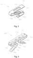
Fig. 1 is a schematic perspective view of a first preferred embodiment of a slide-in clamping device according to the invention for a withdrawable low-voltage circuit breaker unit; -
Fig. 2 is a schematic perspective exploded view of the clamping device ofFig. 1 ; -
Fig. 3 is a schematic perspective view of the displaceable spacer assembly of the clamping device ofFig. 1 ; -
Fig. 4 is a schematic perspective view showing another embodiment of a displaceable spacer assembly which can be used in the clamping device ofFig. 1 ; -
Fig. 5a is a schematic cross-sectional view of the clamping device ofFig. 1 taken along the line V-V inFig. 1 further showing two corresponding electrical terminals of a withdrawable low-voltage circuit breaker unit, one of which is inserted in one of the clamping seats of the clamping device; -
Fig. 5b is a schematic cross-sectional view corresponding toFig. 5a , with both electrical terminals inserted in the clamping seats of the clamping device; -
Figs. 6a-b are schematic side views showing configurations similar to those ofFigs. 5a-b , respectively, wherein the clamping device comprises still another embodiment of a displaceable spacer assembly; -
Fig. 7 is a schematic perspective view of a second preferred embodiment of a slide-in clamping device according to the invention for a withdrawable low-voltage circuit breaker unit; -
Fig. 8 is a schematic perspective exploded view of the clamping device ofFig. 7 ; -
Fig. 9a is a schematic longitudinal sectional view of the clamping device ofFig. 8 taken along the line IX-IX inFig. 7 further showing two electrical terminals of a withdrawable low-voltage circuit breaker unit, one of which is inserted in one of the clamping seats of the clamping device; -
Fig. 9b is a schematic longitudinal sectional view corresponding toFig. 9a , with both electrical terminals inserted in the clamping seats of the clamping device; -
Fig. 10 is a diagram qualitatively showing the behavior of the insertion force as a function of the insertion position during the insertion of an electrical terminal into a clamping seat of the slide-in clamping device ofFig. 1 with (curve A) and without (curve B) the aid of a displaceable spacer assembly according the invention, and -
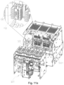
Figs. 11a-b are schematic exploded views of a withdrawable low-voltage circuit breaker unit comprising slide-in clamping devices according to the invention, wherein the slide-in clamping devices are associated with the electrical terminals of the stationary base or, respectively, with the electrical terminals of the withdrawable circuit breaker. - With reference to the above-listed figures, the present invention relates to a slide-in clamping device for withdrawable low-voltage circuit breaker units.
- For the purposes of the present invention, by the term "low-voltage" it is meant an electrical voltage lower than or equal to about 2500 V.
- As shown in
Figs 11a-b , a withdrawable low-voltage circuit breaker unit basically comprises astationary base 302, which is fixed to asuitable supporting structure 3021, such as a case or a frame, and remains permanently electrically wired to a corresponding electrical circuit (not shown), and awithdrawable circuit breaker 301, which can be withdrawn from and mounted again onto thestationary base 302 whenever required, without the need of re-wiring each time the whole unit. Thewithdrawable circuit breaker 301 and thestationary base 302 are per se known and their specific configuration is not relevant for the present invention, therefore they are not described in more detail herein. - The
withdrawable circuit breaker 301 comprises one or moreelectrical terminals 311, in the following also referred to as withdrawableelectrical terminals 311, which are only partially visible inFig. 11b . Correspondingly, thestationary base 302 comprises one or moreelectrical terminals 312, in the following also referred to as stationaryelectrical terminals 312, which are neither visible inFig. 11a , being in this case covered by respective slide-in clamping devices of the invention, nor inFig. 11b , because of the point of view of the figure. When the withdrawable low-voltage circuit breaker unit is assembled, i.e., thewithdrawable circuit breaker 301 is connected to thestationary base 302, eachelectrical terminal 311 of thewithdrawable circuit breaker 301 is mechanically and electrically connected with a correspondingelectrical terminal 312 of thestationary base 302 by means of a respective slide-in clamping device according to the invention. - A first preferred embodiment of such a slide-in clamping device is shown in
Figs 1-6 and is generally indicated at 100. - The slide-in
clamping device 100 comprises afirst clamping seat 110 for receiving one of said withdrawableelectrical terminals 311, or, respectively, of said stationaryelectrical terminals 312, and asecond clamping seat 120 for receiving a corresponding one of said stationaryelectrical terminals 312 or, respectively, of said withdrawableelectrical terminals 311. - The
electrical terminals respective clamping seat openings 111, 112 facing oppositely to each other. The clamping seats 110, 120 have respective slide-in directions which preferably coincide with each other, defining a common slide-in axis X1-X1 of theclamping device 100. - As apparent from
Fig. 1 , the clampingseats members 130 arranged in tworows clamping device 100 containing the slide-in axis X1-X1. More precisely, each clampingmember 130 comprises a first longitudinal end portion defining a clampingfinger 131 of the first clampingseat 110, and a second longitudinal end portion defining a clampingfinger 132 of thesecond clamping seat 120. Therefore, the first clampingseat 110 is at least partially laterally delimited by pairs of respective clampingfingers 131 arranged in two rows facing each other and parallel to each other, coinciding with therows members 130. Similarly, thesecond clamping seat 120 is at least partially laterally delimited by pairs of respective clampingfingers 132 arranged in two rows facing each other and parallel to each other, also coinciding with therows members 130. - As a result, in this preferred embodiment of the slide-in clamping device according the invention, the clamping
seats openings 111, 112. This configuration is particularly suitable for connecting bar-likeelectrical terminals fingers seat 110 and of thesecond clamping seat 120 act as straight clamping jaws on the respectiveelectrical terminal - Preferably, all of the clamping
members 130 have a same configuration. In particular, each clampingmember 130 is preferably integrally formed and is preferably configured as a substantially straight bar with generally rectangular or square cross section, whose size may vary along the longitudinal extension of the bar so as to provide the clampingmember 130 with a longitudinally variable outer profile. - In particular, as better seen in
Fig. 2 , each clampingfinger 131 of thefirst camping seat 110, i.e., each first end portion of the clampingmembers 130, and each clampingfinger 132 of thesecond clamping seat 120, i.e., each second end portion of the clampingmembers 130, preferably comprise aninner contact protrusion 133 projecting inwardly in the first clampingseat 110 or, respectively, second clampingseat 120, at which theclamping finger electrical terminal seat inner contact protrusions 133 may be conveniently configured as solid bulges integrally formed on an inwardly facing surface of therespective clamping finger inner contact protrusions 133 preferably have a round profile in the direction of longitudinal extension of therespective clamping finger electrical terminals respective clamping seat - Each clamping
finger 131 of the first clampingseat 110 and each clampingfinger 132 of thesecond clamping seat 120 preferably also comprises anouter contact protrusion 134, projecting outwardly relative to therespective clamping seat clamping finger elastic means 140 of theclamping device 100, described in more detail below. Theouter contact protrusions 134 may be conveniently configured as wedge-shaped portions integrally formed on an outwardly facing surface of therespective clamping finger respective clamping finger outer contact protrusions 134 preferably have a flat profile in the direction of longitudinal extension of therespective clamping finger abutment notch 135 at the tip of the clampingfinger - Furthermore, each clamping
member 130 preferably comprises atransverse groove 136 formed in or defined on a surface thereof facing inwardly with reference to the operating arrangement of the clampingmember 130 in theclamping device 100. When the clampingmembers 130 are arranged mutually side-by-side in the tworows transverse grooves 136 overall define two straightlongitudinal rails 139, facing each other, for guiding the insertion of and retaining a fixedspacer member 160 of theclamping device 100, described in more detail below. Only one of saidrails 139 is visible inFig. 2 . - As the clamping
fingers members 130, shall also ensure electrical connection between the clampingseats electrical terminals - The
clamping device 100 further comprises bias elastic means which provide the required clamping force at the clampingseats fingers respective clamping members 130, of therows seats rows clamping device 100. - In the preferred embodiment shown in
Figs. 1-6 , the bias elastic means of theclamping device 100 comprise a pair ofleaf springs 140, each acting on arespective row members 130, at the longitudinal end portions thereof. - As better seen in
Fig. 2 , bothleaf springs 140 have a same configuration, comprising twoopposite contact portions rows members 130, and a central connectingportion 143, which connects thecontact portions contact portions prongs 144 corresponding to theplurality clamping members 130 of eachrow members 130. Eachprong 144 of thecontact portion 141 or, respectively, 142 independently contacts the first or, respectively, the second longitudinal end portion of a clampingmember 130, at the respectiveouter contact protrusion 134 described above. - The
rows members 130 and theleaf springs 140 described above are removably received in a mountingframe 150 of theclamping device 100, which helps maintaining the correct mutual position of such components for a proper operation of theclamping device 100. - As better seen still in
Fig. 2 , the mountingframe 150 preferably has a generally rectangular form comprising two long sides formed by respectivelongitudinal bars 151 and two short sides formed by respectivetransverse walls 142, which together delimit a rectangularcentral opening 153. - In an assembled condition of the clamping device (
Fig. 1 ), eachrow members 130 together with therespective leaf spring 140 is arranged along one of thelongitudinal bars 151, with theleaf spring 140 abutting, at its central connectingportion 143, against it. The clampingfingers 130 of thecorresponding row portion 143 of theleaf spring 140 and are contacted, i.e., elastically biased, at the respective longitudinal end portions, byprongs 144 of thecontact portions leaf spring 140. - For maintaining the two
rows members 130 so arranged in the mountingframe 150 at a predetermined distance from each other against the biasing action of theleaf springs 140, a fixedspacer member 160 is interposed between them. The fixedspacer member 160 is preferably configured as a plate having a generally rectangular shape, whose long sides, in the assembled condition of theclamping device 100, are received in the twoopposite rails 139 extending along therows contact members 130. - According to a relevant aspect of the present invention, the slide-in
clamping device 100 comprises adisplaceable spacer assembly 170 to selectively apply to the clampingfingers seats leaf springs 140, acting on thesame clamping fingers seats electrical terminal - In use, one of the clamping
seats electrical terminal withdrawable circuit breaker 301 or, respectively, of thestationary base 302, whereas the other of the clampingseats electrical terminal stationary base 302, or, respectively, of thewithdrawable circuit breaker 301 every time thewithdrawable circuit breaker 301 has to be mounted onto or withdrawn from thestationary base 302. Thedisplaceable spacer assembly 170 is most conveniently used in combination with the clampingseat electrical terminal Figs. 1-6 the clampingseat 110. However, the use of a displaceable spacer assembly having the same structural and functional features of thedisplaceable spacer assembly 170 described hereinafter can be considered also in combination with the respectively other clampingseat seat 120, is not excluded. - The
displaceable spacer assembly 170 comprises adisplaceable spacer member 171 and associated bias elastic means. - The
displaceable spacer member 171 is preferably configured as a plate of rectangular shape. - According to a preferred embodiment of the
displaceable spacer assembly 170, shown inFigs. 1 ,2 ,5a-b , and also separately inFig. 3 , the bias elastic means of thedisplaceable spacer assembly 170 comprise a V-shapedcantilever spring 172. Thecantilever spring 172 is fixedly connected to, preferably integrally formed with, the plate forming thedisplaceable spacer member 171, at a short side thereof. Thecantilever spring 172 comprises afirst leg 1721, intended to abut against a suitable abutment surface within theclamping device 100, as better explained below, and asecond leg 1722, which is connected to thedisplaceable spacer member 171. - The
first leg 1721 may comprise a throughopening 1723 for a fastening means, such as a screw (not shown), for removably connecting thecantilever spring 172, i.e., thedisplaceable spacer assembly 170, to the said abutment surface. Correspondingly, also thesecond leg 1722 and thedisplaceable spacer member 171 may comprise a respective throughopening openings displaceable spacer assembly 170 is positioned in theclamping device 100. The throughopenings - According to another preferred embodiment of the displaceable spacer assembly, shown separately in
Fig. 4 and indicated generally with reference numeral 170', the displaceable spacer assembly bias elastic means comprise two V-shaped cantilever springs 173. The cantilever springs 173 are fixedly connected to, preferably integrally formed with, the plate forming thedisplaceable spacer member 171, at the short sides thereof, with a mutually symmetrical arrangement. The cantilever springs 173 preferably have a same configuration, comprising a first leg 1731, intended to abut against a suitable abutment surface within theclamping device 100, and a second leg 1732, which is connected to thedisplaceable spacer member 171. - Each
cantilever spring 173 may comprise first throughopenings 1733 formed in the legs 1731, 1732, and second throughopenings 1734 formed at bend sections respectively connecting the two legs 1731, 1732 to each other and thecantilever spring 173 to thedisplaceable spacer member 171. Both the first throughopenings 1733 and the second throughopenings 1734 may be advantageously configured as slots with an elongated shape. The first throughopenings 1733 have mainly a lightening function, whereas by properly choosing the length and width of the second throughopenings 1734 it is possible to adjust the elastic response of thecorresponding cantilever spring 173. One or more throughopenings 1716 my also be provided in thedisplaceable spacer member 171, for facilitating the extraction of the displaceable spacer assembly from therespective clamping seat - According to a further preferred embodiment of the displaceable spacer assembly, shown in
Figs. 6a-b and indicated generally withreference numeral 170", the displaceable spacer assembly bias elastic means comprise acompression coil spring 174. At one end thereof, thecompression coil spring 174 is connected to one of the faces of thedisplaceable spacer member 171, whereas the other end thecompression coil spring 174 abuts against a suitable abutment surface within theclamping device 100. - All of the above-described embodiments of the
displaceable spacer assembly clamping device 100, as explained in more detail hereinafter with reference in particular toFigs. 5a-b and 6a-b . - As apparent from
Figs. 5a-b and 6a-b , as well as fromFig. 1 , thedisplaceable spacer assembly seat 110. The biaselastic means spacer member 160. When theclamping device 100 does not comprise a fixed spacer member, the bias elastic means may abut against portions of the mountingframe 150 of theclamping device 100 or also against an electrical terminal received in the other, opposite, clampingseat 120 of theclamping device 100. - The
displaceable spacer member 171 is displaceable within the clampingseat 110, along the slide-in axis X1-X1, between an active position, shown inFigs. 1 ,5a, and 6a , and an inactive position, shown inFigs. 5b and 6b . - In the active position, the
displaceable spacer member 171, under the action of the respective bias elastic means 172 (Fig. 5a-b ) or 174 (Figs. 6a-b ), contacts the twoopposite rows fingers 131 of the clampingseat 110, i.e., of corresponding first longitudinal end portions of the clampingmembers 130 of theclamping device 100, urging them away from each other in the clamping direction, i.e., along the transverse axis Y-Y. In this position, therefore, thedisplaceable spacer member 171 spreads therows fingers 131 apart from each other to a certain predetermined extent against the opposite biasing force generated by the leaf springs 140. This promotes the insertion of theelectrical terminal 311 into the clampingseat 110, reducing the insertion force required for this purpose. - By properly choosing the size of the
displaceable spacer member 171 and setting the elastic response of the displaceable spacer assembly biaselastic means rows fingers 131 subjected to the biasing force generated by theleaf springs 140, or by other bias elastic means of theclamping device 100, and thus a corresponding predetermined extent to which the force for inserting an electrical terminal into the clampingseat 110 is reduced. - When the
displaceable spacer member 171 is in the active position described above, the clampingseat 110 is in a rest condition, ready for receiving a corresponding electrical terminal. In this condition, thedisplaceable spacer member 171 autonomously remains in its active position under the sole action of the biaselastic means displaceable spacer assembly 170. Moreover, in this condition thedisplaceable spacer member 171 is retained within the clampingseat 110 only by means of therespective clamping fingers 131, namely by the respectiveinner contact protrusions 133. - Upon insertion of an electrical terminal, here the
electrical terminal 311, into the clampingseat 131, thedisplaceable spacer member 171 of thedisplaceable spacer assembly electrical terminal 311, while the biaselastic means - When the
electrical terminal 311 is fully inserted in thelamping seat 110, thedisplaceable spacer member 171 reaches its inactive position. In this position, thedisplaceable spacer member 171 does not apply any significant force to therows fingers 131. Preferably, in this position, thedisplaceable spacer member 171 does not contact therows displaceable spacer member 171 is in this position, the clampingfingers 131 may fully develop their clamping action under the biasing force of theleaf springs 140, for a secure and tight clamping connection with theelectrical terminal 311. This condition represents the operating condition of the clampingseat 110. - When the
electrical terminal 311 is withdrawn from the clampingseat 110, thedisplaceable spacer member 171 autonomously returns to its active position under the sole action of the biaselastic means seat 110 returns in its rest condition. -
Figs. 7-9 show a second preferred embodiment of a slide-in clamping device according to the invention, generally indicated at 200. - As in the first embodiment described above, the slide-in
clamping device 200 comprises afirst clamping seat 210 for receiving one of the withdrawableelectrical terminals 311, or, respectively, of the stationaryelectrical terminals 312 of the withdrawable low-voltage circuit breaker unit, and asecond clamping seat 220 for receiving a corresponding one of said stationaryelectrical terminals 312 or, respectively, of said withdrawableelectrical terminals 312. The clamping seats 210, 220 have respective slide-inopenings clamping device 200. - As apparent in particular from
Fig. 7 , the clampingseats members 230 facing each other and circumferentially arranged about the longitudinal axis X2-X2. - Each clamping
member 230 comprises a first longitudinal end portion defining a clampingfinger 231 of the first clampingseat 210, and a second longitudinal end portion defining a clampingfinger 232 of thesecond clamping seat 220. Therefore, the first clampingseat 210 is laterally delimited by pairs of circumferentially arranged respective clampingfingers 231. Similarly, thesecond clamping seat 220 is laterally delimited by pairs of circumferentially arranged respective clampingfingers 232. As a result, in this preferred embodiment of the slide-in clamping device according the invention, each clamping seats 210, 220 has a substantially cylindrical, or tulip-like, configuration, open at the respective slide-inopening 211 or 212. This configuration is particularly suitable for connecting finger-likeelectrical terminals - Preferably, all of the clamping
members 230 have a same configuration. In particular, each clampingmember 230 is preferably integrally formed and is preferably configured as a rectangular plate which is substantially straight in a first extension direction thereof, intended to lie parallel to the longitudinal axis X2-X2 of theclamping device 200 in the assembled condition, and curved in a second extension direction, intended to lie in a circumferential direction of theclamping device 200 in the assembled condition. - As better seen in
Fig. 8 , each clampingfinger 231 of thefirst camping seat 210, i.e., each first end portion of the clampingmembers 230, and each clampingfinger 232 of thesecond clamping seat 220, i.e., each second end portion of the clampingmembers 230, preferably comprise agroove 233 extending in said second extension direction of therespective clamping member 230, i.e., circumferentially in the assembled state of theclamping device 200. Eachgroove 233 has a convex side projecting inwardly in the first clampingseat 110 or, respectively, second clampingseat 120, which defines aninner contact protrusion 2331 at which theclamping finger electrical terminal seat inner contact protrusion 2331 preferably has a round profile in said first extension direction of therespective clamping member 230; i.e., longitudinally in the assembled state of theclamping device 200. Eachgroove 233 also has a concave side, recessed relative to an outer surface of therespective clamping member 230, which conveniently defines aseat 2332 for biaselastic means 240 of theclamping device 200, described in more detail below. - As in the first embodiment of the clamping device described above, the clamping
fingers members 230, are made of a material, in particular a metal or metal alloy, having good electrical conductivity, such as for example copper, for ensuring electrical connection between the clampingseats electrical terminals - The
clamping device 200 further comprises bias elastic means which provide the required clamping force at the clampingseats respective clamping fingers members 230, towards each other in a radial direction perpendicular to the longitudinal axis X2-X2 of theclamping device 200. In the preferred embodiment shown inFigs. 7-9 , the bias elastic means of theclamping device 200 comprise a pair of annular traction coil springs 240 received in the above-mentionedseats 2332 and circumferentially surrounding the clampingseats members 230 may remain at a predetermined mutual distance also under the biasing action of the traction coil springs 240 by circumferentially abutting against each other, also in this case a fixed spacedmember 260 may be conveniently interposed between the clampingmembers 230 for improving the overall assembly of theclamping device 200. The fixedspacer member 260 is preferably configured as a plate having a circular shape. Alternatively, the fixedspacer member 260 could be configured as a circular ring (not shown). Preferably, the fixedspacer member 260 comprisesperipheral projections 261 intended to engage corresponding recesses or throughopenings 234 formed in the clampingmembers 230. Preferably, the number ofprojections 261 is the same as the number of clampingmembers 230 in theclamping device 200. - In this case, as a result of the cylindrical symmetry and of the features described above, the
clamping device 200 maintains its assembled condition in a dynamic way, under the sole action of the annular traction coil springs 240 and of the fixedspacer member 260, without the aid of an additional mounting frame. - According to the invention, the slide-in
clamping device 200 also comprises adisplaceable spacer assembly 270 to selectively apply to the clampingfingers seats same clamping fingers 231 or 1232, for facilitating the insertion into the clampingseats electrical terminal Figs. 7-9 thedisplaceable spacer assembly 270 is received, preferably removably, in the clampingseat 210 and acts on the corresponding clampingfingers 231. Thedisplaceable spacer assembly 270 comprises adisplaceable spacer member 271 and associated bias elastic means. Thedisplaceable spacer member 271 is preferably configured as a plate having a circular shape. In view of the cylindrical base geometry of theclamping device 200, the bias elastic means of thedisplaceable spacer assembly 270 are preferably configured as acompression coil spring 272. At one end thereof, thecompression coil spring 272 is connected to one of the faces of thedisplaceable spacer member 271, whereas the other end thecoil compression spring 272 abuts against the fixedspacer member 260. When the fixedspacer member 260 is formed as circular ring, thecompression coil spring 272 may extend through the fixedspacer member 260 and abut against an electrical terminal received in the other, opposite, clampingseat 220 of theclamping device 200. - The operation principle of the
displaceable spacer assembly 270 is shown inFigs. 9a-b and it is similar to the operation principle of thedisplaceable spacer assembly 170 in theclamping device 100, already described above with reference to the first preferred embodiment of the invention, therefore it will be not explained again in detail here. -
Fig. 10 qualitatively shows the behavior of the insertion force as a function of the insertion position during the insertion of an electrical terminal into a clamping seat of a clamping device with a "jaw" configuration, similar to that shown inFigs. 1-6 . Curve A represents the behavior of the insertion force during the insertion of an electrical terminal into a clamping seat provided with a displaceable spacer assembly according to the invention, whereas curve B represents the behavior of the insertion force during the insertion of the same electrical terminal into the same clamping seat without a displaceable spacer assembly, as in clamping devices of the prior art. By comparing the two curves it is apparent that the use of a spacer assembly according to the invention brings about a reduction of the insertion force during the initial phase of the insertion, as well as a significant lowering of the peak value reached during the insertion process. - The present invention thus provides a simple, effective, and economic technical solution for reducing the insertion force required for inserting an electrical terminal of a withdrawable low-voltage circuit breaker unit into a clamping seat of a slide-in clamping device used for mechanically and electrically connecting a pair of corresponding electrical terminals of such unit, which solution can be easily implemented both in new slide-in clamping devices and in existing clamping devices as a retrofit measure.
- As it will be readily apparent to those skilled in the art, many modifications can be made to the embodiments of the clamping device according to the invention described in detail above, without departing from the scope of the invention as defined by the appended claims.
- By way of example, in the first embodiment shown in
Figs. 1-6 the clampingfingers 131 of the clampingseat 110 could be separately formed relative to the clampingfingers 132 of the clampingseat 120. The clampingfingers members 130, could be differently secured in the mountingframe 150, for example pivotally by means of pins, and the fixedspacer member 160 could be omitted. The bias elastic means of the clamping device could be differently configured, for example as compression coil spring assemblies acting on each row of clampingfingers 131 or, respectively, 132 separately. In the embodiment shown inFigs. 7-9 a mounting frame could be provided for maintaining the clampingmembers 230 in the desired mutual position in the assembled state of the clamping device, and the clampingfingers 231 of the clampingseat 210 could be separately formed relative to the clampingfingers 232 of the clampingseat 220.
Claims (21)
- Slide-in clamping device (100; 200) for removably connecting a first electrical terminal (311) of a withdrawable low-voltage circuit breaker (301) to a corresponding second electrical terminal (312) of a respective stationary base (302) in a withdrawable low-voltage circuit breaker unit, the clamping device (100; 200) comprising:- at least one pair of first clamping fingers (131; 231) facing each other and at least partially laterally delimiting a first clamping seat (110; 210) for one of said first and second electrical terminals (311, 312), the first clamping seat (110; 210) comprising a respective slide-in opening (111; 211);- at least one pair of second clamping fingers (132; 232) facing each other and at least partially laterally delimiting a second clamping seat (120; 220) for the other of said first and second electrical terminals (311, 312), the second clamping seat (120; 220) comprising a respective slide-in opening (121; 221) facing oppositely relative to the slide-in opening (111; 211) of the first clamping seat (110; 210), and- bias elastic means (140; 240) acting on said at least one pair of first clamping fingers (131; 231) and said at least one pair of second clamping fingers (132; 232) so as to urge the clamping fingers (131, 132; 231, 232) of each pair towards each other in a clamping direction (Y-Y) substantially perpendicular to respective slide-in directions (X1-X1; X2-X2) of said first clamping seat (110; 210) and said second clamping seat (120; 220),characterized by comprising at least one displaceable spacer assembly (170, 170', 170"; 270) having a displaceable spacer member (171; 271), wherein the displaceable spacer member (171; 271) is displaceable between an active position, in which the displaceable spacer member (171; 271) contacts the first clamping fingers (131; 231) of the at least one pair of first clamping fingers or the second clamping fingers (132; 232) of the at least one pair of second clamping fingers urging them away from each other in the clamping direction (Y-Y), and an inactive position, in which the displaceable spacer member (171; 271) does not apply any force to said first clamping fingers (131; 231) or said second clamping fingers (132; 232).
- Clamping device (100; 200) according to claim 1, wherein the at least one displaceable spacer assembly (170, 170', 170"; 270) comprises displaceable spacer assembly bias elastic means (172, 173, 174; 272) urging the displaceable spacer member (171; 271) towards said active position.
- Clamping device (100; 200) according to any one of the previous claims, wherein the at least one displaceable spacer assembly (170, 170', 170"; 270) is fully received, preferably removably, in said first clamping seat (110; 210) or in said second clamping seat (120; 220).
- Clamping device (100; 200) according to any one of the previous claims, wherein the displaceable spacer member (171; 271) is displaceable along the slide-in direction (X1-X1; X2-X2) of said first clamping seat (110; 210) or said second clamping seat (120; 220).
- Clamping device (100; 200) according to any one of the previous claims, wherein the displaceable spacer member (171; 271) is displaceable by said first electrical terminal (311) or said second electrical terminal (312) upon insertion thereof in the respective clamping seat (110, 120; 210, 220).
- Clamping device (100; 200) according to any one of the previous claims, wherein, when said first electrical terminal (311) or said second electrical terminal (312) is fully inserted in the respective clamping seat (110, 120; 210, 220), the displaceable spacer member (171; 271) is in said inactive position.
- Clamping device (100; 200) according to any one of the previous claims, wherein, when said first electrical terminal (311) or said second electrical terminal (312) is fully withdrawn from the respective clamping seat (110, 120; 210, 220)., the displaceable spacer member (171; 271) is in said active position.
- Clamping device (100; 200) according to any one of the previous claims, wherein the displaceable spacer member (171; 271) is configured as a plate.
- Clamping device (100; 200) according to any one of claims 2 to 8, wherein the displaceable spacer assembly bias elastic means (172, 173, 174; 272) are selected from the group consisting of cantilever springs, compression coil springs, and any combinations thereof.
- Clamping device (100; 200) according to any one of the previous claims, wherein the slide-in directions (X1-X1; X2-X2) of the first clamping seat (110; 210) and of the second clamping seat (120; 220) substantially coincide with each other.
- Clamping device (100; 200) according to any one of the previous claims, comprising at least one pair of integrally formed clamping members (130; 230) facing each other and at least partially laterally delimiting both the first clamping seat (110; 210) and the second clamping seat (120; 220), wherein the first clamping fingers (131; 231) of said at least one pair of first clamping fingers are defined by first longitudinal end portions of said clamping members (130; 230) and the second clamping fingers (132; 232) of said at least one pair of second clamping fingers are defined by second longitudinal end portions of said clamping members (130; 230).
- Clamping device (100; 200) according to claim 11, comprising a fixed spacer member (160; 260) interposed between the clamping members (130; 230) of said at least one pair of clamping members for maintaining said clamping members (130; 230) at a predetermined distance from each other against the action of said bias elastic means (140; 240).
- Clamping device (100) according to claim 11 or 12, comprising a plurality of pairs of clamping members (130) arranged in two rows (137, 138) facing each other and extending parallel to a longitudinal midplane of the clamping device (100) containing the slide-in directions (X1-X1) of said first clamping seat (110) and said second clamping seat (120).
- Clamping device (100) according to claim 13, wherein the bias elastic means comprise a pair of leaf springs (140) each acting on one of said rows (137, 138) of clamping members (130) at the respective longitudinal end portions.
- Clamping device (100) according to claim 14, wherein each of said leaf springs (140) comprises two opposite contact portions (141, 142) for contacting the respective row (137, 138) of clamping members (130) at the longitudinal end portions thereof, and a central connecting portion (143) which connects said contact portions (141, 142), and wherein each of said contact portions (141, 142) has a comb-like structure comprising a plurality of prongs (144) corresponding to the plurality of pairs of said clamping members (130).
- Clamping device (200) according to claim 11 or 12, comprising at least one pair of clamping members (230) circumferentially arranged about a longitudinal axis defined by the slide-in directions (X2-X2) of said first clamping seat (210) and said second clamping seat (220).
- Clamping device (200) according to claim 16, wherein the bias elastic means comprise a pair of compression rings (240) circumferentially surrounding the at least one pair of clamping members (230) at longitudinal end portions thereof.
- Clamping device (200) according to claim 16 o 17, wherein said at least one pair of clamping members (230) are arranged in the clamping device (200) without the aid of a mounting frame.
- Clamping device (100, 200) according to any one of claims 12 to 18, wherein the displaceable spacer assembly bias elastic means (172, 173, 174; 272), at a side thereof opposite to the displaceable spacer member (171, 271), abut against said fixed spaced member (160; 260).
- Clamping device (100, 200) according to any one of the previous claims, wherein the displaceable spacer assembly bias elastic means (172, 173, 174; 272), at a side thereof opposite to the displaceable spacer member (171; 271), abut against one of said first and second electrical terminals (311, 312) received in the clamping seat (110, 120; 210, 220) other than the one where the displaceable spacer assembly (170, 170'. 170"; 270) acts.
- Withdrawable low-voltage circuit breaker unit, comprising a withdrawable low-voltage circuit breaker (301) having at least one first electrical terminal (311), a stationary base (302) having at least one corresponding second electrical terminal (312), and a slide-in clamping device (100; 200) according to any one of the previous claims which removably connects said first and second electrical terminals (311, 312) to each other.
Priority Applications (3)
| Application Number | Priority Date | Filing Date | Title |
|---|---|---|---|
| EP23189362.9A EP4503354B1 (en) | 2023-08-03 | 2023-08-03 | Clamping device for a withdrawable low-voltage circuit breaker unit |
| US18/790,031 US20250046532A1 (en) | 2023-08-03 | 2024-07-31 | Clamping device for a withdrawable low-voltage circuit breaker unit |
| CN202411051269.2A CN119446856A (en) | 2023-08-03 | 2024-08-01 | Clamping device for withdrawable low-voltage circuit breaker units |
Applications Claiming Priority (1)
| Application Number | Priority Date | Filing Date | Title |
|---|---|---|---|
| EP23189362.9A EP4503354B1 (en) | 2023-08-03 | 2023-08-03 | Clamping device for a withdrawable low-voltage circuit breaker unit |
Publications (3)
| Publication Number | Publication Date |
|---|---|
| EP4503354A1 true EP4503354A1 (en) | 2025-02-05 |
| EP4503354B1 EP4503354B1 (en) | 2026-02-18 |
| EP4503354C0 EP4503354C0 (en) | 2026-02-18 |
Family
ID=87556221
Family Applications (1)
| Application Number | Title | Priority Date | Filing Date |
|---|---|---|---|
| EP23189362.9A Active EP4503354B1 (en) | 2023-08-03 | 2023-08-03 | Clamping device for a withdrawable low-voltage circuit breaker unit |
Country Status (3)
| Country | Link |
|---|---|
| US (1) | US20250046532A1 (en) |
| EP (1) | EP4503354B1 (en) |
| CN (1) | CN119446856A (en) |
Families Citing this family (1)
| Publication number | Priority date | Publication date | Assignee | Title |
|---|---|---|---|---|
| JP7601484B2 (en) * | 2020-07-31 | 2024-12-17 | TE Connectivity Japan合同会社 | Contact Assembly |
Citations (4)
| Publication number | Priority date | Publication date | Assignee | Title |
|---|---|---|---|---|
| DE1095915B (en) * | 1954-05-29 | 1960-12-29 | Siemens Ag | Contact device for retractable or pull-out switch units or isolators |
| CN2349686Y (en) * | 1998-11-28 | 1999-11-17 | 于世根 | Clamp press type insulating contact |
| CN104377048B (en) * | 2014-12-04 | 2017-01-18 | 哈尔滨理工大学 | Electric moving contact with elastic mechanism and structure |
| DE102016217667B4 (en) * | 2016-09-15 | 2020-04-02 | Te Connectivity Germany Gmbh | Electrical contact with rolling contact bodies on opposite sides and plug connection with such a contact |
-
2023
- 2023-08-03 EP EP23189362.9A patent/EP4503354B1/en active Active
-
2024
- 2024-07-31 US US18/790,031 patent/US20250046532A1/en active Pending
- 2024-08-01 CN CN202411051269.2A patent/CN119446856A/en active Pending
Patent Citations (4)
| Publication number | Priority date | Publication date | Assignee | Title |
|---|---|---|---|---|
| DE1095915B (en) * | 1954-05-29 | 1960-12-29 | Siemens Ag | Contact device for retractable or pull-out switch units or isolators |
| CN2349686Y (en) * | 1998-11-28 | 1999-11-17 | 于世根 | Clamp press type insulating contact |
| CN104377048B (en) * | 2014-12-04 | 2017-01-18 | 哈尔滨理工大学 | Electric moving contact with elastic mechanism and structure |
| DE102016217667B4 (en) * | 2016-09-15 | 2020-04-02 | Te Connectivity Germany Gmbh | Electrical contact with rolling contact bodies on opposite sides and plug connection with such a contact |
Also Published As
| Publication number | Publication date |
|---|---|
| EP4503354B1 (en) | 2026-02-18 |
| US20250046532A1 (en) | 2025-02-06 |
| EP4503354C0 (en) | 2026-02-18 |
| CN119446856A (en) | 2025-02-14 |
Similar Documents
| Publication | Publication Date | Title |
|---|---|---|
| CA2246797C (en) | Electrical connector assembly having high current-carrying capability and low insertion force | |
| US9601856B2 (en) | Connecting device for a switchgear apparatus | |
| US3201556A (en) | Self-aligning disconnect assembly | |
| KR100846886B1 (en) | Spring plug terminal | |
| EP2917926B1 (en) | Contact-finger-element and tulip-contact-assembly for switching device | |
| CN106340743B (en) | A kind of cylindrical hat spring | |
| US20250046532A1 (en) | Clamping device for a withdrawable low-voltage circuit breaker unit | |
| US8979600B2 (en) | Fuse holder and fuse clip assembly with dual directional bias element support | |
| EP2096714B1 (en) | Electrical connection device with contact spring operated by a lever having an inlet opening for the end of an electric cable | |
| JP4638884B2 (en) | Integrated brush holder holding system | |
| EP3164913B1 (en) | Plug adapter for an electrical device for plugging in supply lines, and system formed by a plug adapter and a device | |
| EP4391241A1 (en) | High voltage electrical terminal with compliant contact insert | |
| EP0063703A2 (en) | Terminal connecting device for pulling-type breaker | |
| US2935632A (en) | Shunt for carbon brush | |
| US2760034A (en) | High pressure contacts | |
| EP1346386B1 (en) | Current limiting circuit breaker | |
| JP4695654B2 (en) | Pluggable combination device especially for protection against overvoltage | |
| JPH0760706B2 (en) | Electrical connection | |
| EP3232456B1 (en) | Contact assembly for electrically and mechanically connecting a first terminal of a first apparatus to a second terminal of a second apparatus | |
| BR102024017979A2 (en) | FIXING DEVICE FOR A WITHDRAWABLE LOW-VOLTAGE CIRCUIT BREAKER UNIT | |
| GB1589648A (en) | Electrical terminal unit | |
| CN113474864A (en) | Grounding switch for a switchgear and switchgear | |
| KR200407500Y1 (en) | Disconnect contacts of draw-out air circuit breakers | |
| GB1577153A (en) | Electrical connectors | |
| US2090754A (en) | Electric circuit interrupter |
Legal Events
| Date | Code | Title | Description |
|---|---|---|---|
| PUAI | Public reference made under article 153(3) epc to a published international application that has entered the european phase |
Free format text: ORIGINAL CODE: 0009012 |
|
| STAA | Information on the status of an ep patent application or granted ep patent |
Free format text: STATUS: THE APPLICATION HAS BEEN PUBLISHED |
|
| AK | Designated contracting states |
Kind code of ref document: A1 Designated state(s): AL AT BE BG CH CY CZ DE DK EE ES FI FR GB GR HR HU IE IS IT LI LT LU LV MC ME MK MT NL NO PL PT RO RS SE SI SK SM TR |
|
| STAA | Information on the status of an ep patent application or granted ep patent |
Free format text: STATUS: REQUEST FOR EXAMINATION WAS MADE |
|
| 17P | Request for examination filed |
Effective date: 20250612 |
|
| GRAP | Despatch of communication of intention to grant a patent |
Free format text: ORIGINAL CODE: EPIDOSNIGR1 |
|
| STAA | Information on the status of an ep patent application or granted ep patent |
Free format text: STATUS: GRANT OF PATENT IS INTENDED |
|
| RIC1 | Information provided on ipc code assigned before grant |
Ipc: H02B 11/04 20060101AFI20250915BHEP Ipc: H02B 11/12 20060101ALI20250915BHEP Ipc: H01R 13/193 20060101ALI20250915BHEP Ipc: H01R 13/11 20060101ALI20250915BHEP Ipc: H01H 71/08 20060101ALI20250915BHEP Ipc: H01R 13/18 20060101ALN20250915BHEP |
|
| INTG | Intention to grant announced |
Effective date: 20250929 |
|
| GRAS | Grant fee paid |
Free format text: ORIGINAL CODE: EPIDOSNIGR3 |
|
| GRAL | Information related to payment of fee for publishing/printing deleted |
Free format text: ORIGINAL CODE: EPIDOSDIGR3 |
|
| GRAS | Grant fee paid |
Free format text: ORIGINAL CODE: EPIDOSNIGR3 |
|
| GRAA | (expected) grant |
Free format text: ORIGINAL CODE: 0009210 |
|
| STAA | Information on the status of an ep patent application or granted ep patent |
Free format text: STATUS: THE PATENT HAS BEEN GRANTED |
|
| AK | Designated contracting states |
Kind code of ref document: B1 Designated state(s): AL AT BE BG CH CY CZ DE DK EE ES FI FR GB GR HR HU IE IS IT LI LT LU LV MC ME MK MT NL NO PL PT RO RS SE SI SK SM TR |
|
| REG | Reference to a national code |
Ref country code: CH Ref legal event code: F10 Free format text: ST27 STATUS EVENT CODE: U-0-0-F10-F00 (AS PROVIDED BY THE NATIONAL OFFICE) Effective date: 20260218 Ref country code: GB Ref legal event code: FG4D |
|
| REG | Reference to a national code |
Ref country code: IE Ref legal event code: FG4D |
|
| REG | Reference to a national code |
Ref country code: DE Ref legal event code: R096 Ref document number: 602023012109 Country of ref document: DE |
|
| U01 | Request for unitary effect filed |
Effective date: 20260311 |
|
| U07 | Unitary effect registered |
Designated state(s): AT BE BG DE DK EE FI FR IT LT LU LV MT NL PT RO SE SI Effective date: 20260318 |
|
| PG25 | Lapsed in a contracting state [announced via postgrant information from national office to epo] |
Ref country code: RS Free format text: LAPSE BECAUSE OF FAILURE TO SUBMIT A TRANSLATION OF THE DESCRIPTION OR TO PAY THE FEE WITHIN THE PRESCRIBED TIME-LIMIT Effective date: 20260518 |
|
| PG25 | Lapsed in a contracting state [announced via postgrant information from national office to epo] |
Ref country code: ES Free format text: LAPSE BECAUSE OF FAILURE TO SUBMIT A TRANSLATION OF THE DESCRIPTION OR TO PAY THE FEE WITHIN THE PRESCRIBED TIME-LIMIT Effective date: 20260218 |
|
| PG25 | Lapsed in a contracting state [announced via postgrant information from national office to epo] |
Ref country code: PL Free format text: LAPSE BECAUSE OF FAILURE TO SUBMIT A TRANSLATION OF THE DESCRIPTION OR TO PAY THE FEE WITHIN THE PRESCRIBED TIME-LIMIT Effective date: 20260218 |
|
| PG25 | Lapsed in a contracting state [announced via postgrant information from national office to epo] |
Ref country code: GR Free format text: LAPSE BECAUSE OF FAILURE TO SUBMIT A TRANSLATION OF THE DESCRIPTION OR TO PAY THE FEE WITHIN THE PRESCRIBED TIME-LIMIT Effective date: 20260519 |
|
| PG25 | Lapsed in a contracting state [announced via postgrant information from national office to epo] |
Ref country code: NO Free format text: LAPSE BECAUSE OF FAILURE TO SUBMIT A TRANSLATION OF THE DESCRIPTION OR TO PAY THE FEE WITHIN THE PRESCRIBED TIME-LIMIT Effective date: 20260518 |
|
| PG25 | Lapsed in a contracting state [announced via postgrant information from national office to epo] |
Ref country code: HR Free format text: LAPSE BECAUSE OF FAILURE TO SUBMIT A TRANSLATION OF THE DESCRIPTION OR TO PAY THE FEE WITHIN THE PRESCRIBED TIME-LIMIT Effective date: 20260218 |
|
| PG25 | Lapsed in a contracting state [announced via postgrant information from national office to epo] |
Ref country code: IS Free format text: LAPSE BECAUSE OF FAILURE TO SUBMIT A TRANSLATION OF THE DESCRIPTION OR TO PAY THE FEE WITHIN THE PRESCRIBED TIME-LIMIT Effective date: 20260618 |