EP4503341A1 - Connection structure and electronic device - Google Patents
Connection structure and electronic device Download PDFInfo
- Publication number
- EP4503341A1 EP4503341A1 EP23896306.0A EP23896306A EP4503341A1 EP 4503341 A1 EP4503341 A1 EP 4503341A1 EP 23896306 A EP23896306 A EP 23896306A EP 4503341 A1 EP4503341 A1 EP 4503341A1
- Authority
- EP
- European Patent Office
- Prior art keywords
- groove
- structural member
- metal structural
- middle frame
- electronic device
- Prior art date
- Legal status (The legal status is an assumption and is not a legal conclusion. Google has not performed a legal analysis and makes no representation as to the accuracy of the status listed.)
- Pending
Links
Images










Classifications
-
- G—PHYSICS
- G06—COMPUTING OR CALCULATING; COUNTING
- G06F—ELECTRIC DIGITAL DATA PROCESSING
- G06F1/00—Details not covered by groups G06F3/00 - G06F13/00 and G06F21/00
- G06F1/16—Constructional details or arrangements
- G06F1/1601—Constructional details related to the housing of computer displays, e.g. of CRT monitors, of flat displays
-
- G—PHYSICS
- G06—COMPUTING OR CALCULATING; COUNTING
- G06F—ELECTRIC DIGITAL DATA PROCESSING
- G06F1/00—Details not covered by groups G06F3/00 - G06F13/00 and G06F21/00
- G06F1/16—Constructional details or arrangements
- G06F1/1613—Constructional details or arrangements for portable computers
- G06F1/1633—Constructional details or arrangements of portable computers not specific to the type of enclosures covered by groups G06F1/1615 - G06F1/1626
-
- G—PHYSICS
- G06—COMPUTING OR CALCULATING; COUNTING
- G06F—ELECTRIC DIGITAL DATA PROCESSING
- G06F1/00—Details not covered by groups G06F3/00 - G06F13/00 and G06F21/00
- G06F1/16—Constructional details or arrangements
- G06F1/18—Packaging or power distribution
- G06F1/183—Internal mounting support structures, e.g. for supporting printed circuit boards
-
- H—ELECTRICITY
- H04—ELECTRIC COMMUNICATION TECHNIQUE
- H04M—TELEPHONIC COMMUNICATION
- H04M1/00—Substation equipment, e.g. for use by subscribers
- H04M1/02—Constructional features of telephone sets
- H04M1/0202—Portable telephone sets, e.g. cordless phones, mobile phones or bar type handsets
- H04M1/0249—Details of the mechanical connection between the housing parts or relating to the method of assembly
-
- H—ELECTRICITY
- H04—ELECTRIC COMMUNICATION TECHNIQUE
- H04M—TELEPHONIC COMMUNICATION
- H04M1/00—Substation equipment, e.g. for use by subscribers
- H04M1/02—Constructional features of telephone sets
- H04M1/0202—Portable telephone sets, e.g. cordless phones, mobile phones or bar type handsets
- H04M1/026—Details of the structure or mounting of specific components
-
- H—ELECTRICITY
- H05—ELECTRIC TECHNIQUES NOT OTHERWISE PROVIDED FOR
- H05K—PRINTED CIRCUITS; CASINGS OR CONSTRUCTIONAL DETAILS OF ELECTRIC APPARATUS; MANUFACTURE OF ASSEMBLAGES OF ELECTRICAL COMPONENTS
- H05K9/00—Screening of apparatus or components against electric or magnetic fields
- H05K9/0073—Shielding materials
- H05K9/0081—Electromagnetic shielding materials, e.g. EMI, RFI shielding
- H05K9/0088—Electromagnetic shielding materials, e.g. EMI, RFI shielding comprising a plurality of shielding layers; combining different shielding material structure
Definitions
- Embodiments of this application relate to the field of terminal technologies, and in particular, to a connection structure and an electronic device.
- a near field communication (Near Field Communication, NFC) technology-based coil module is electrically connected to a circuit board by elastically connecting a spring sheet.
- An antenna functional spring sheet on the circuit board is electrically connected to a middle frame by riveting a metal member.
- a display is electrically connected to the middle frame by welding a metal sheet and by using conductive foam.
- Embodiments of this application provide a connection structure and an electronic device, which can avoid existence of a gap between a metal structural member and a circuit board in scenarios such as falling, and can further avoid a problem of poor overall performance due to poor contact between the metal structural member and the circuit board or between the circuit board and a middle frame.
- an embodiment of this application provides an electronic device.
- the electronic device includes at least a middle frame, a metal structural member, and a fastener;
- the metal structural member has a first through hole, the middle frame has a second through hole, and the fastener passes through the first through hole and the second through hole;
- at least one through groove is provided on the metal structural member, a surface of the through groove facing away from the middle frame is recessed, and the through groove extends to at least one outer edge of the metal structural member; and a surface of the through groove facing the middle frame is protruded.
- the fastener can fixedly connect the metal structural member and the middle frame by passing the fastener through the first through hole on the metal structural member and the second through hole on the middle frame.
- the at least one through groove is provided on the metal structural member, the surface of the through groove facing away from the middle frame is recessed, the through groove extends to the at least one outer edge of the metal structural member, and the surface of the through groove facing the middle frame is protruded.
- the through groove can squeeze the middle frame, to absorb a gap between the metal structural member and the middle frame. Therefore, existence of a gap between the metal structural member and the middle frame in scenarios such as falling can be avoided, and a problem of poor overall performance of the electronic device due to poor contact between the metal structural member and the middle frame can be further avoided.
- the through groove is formed by using a stamping process.
- the stamping process has advantages of high production efficiency and low material consumption. Therefore, forming the through groove on the metal structural member by using the stamping process can improve efficiency of producing the through groove, and can fully utilize the metal structural member, thereby avoiding a waste of costs.
- the stamping process has relatively high size precision and relatively good processing stability.
- the through groove is provided close to the first through hole.
- the through groove is provided at a location close to the first through hole. Because the surface of the through groove facing the middle frame is protruded, at a location of the through groove closer to the first through hole, a groove bottom of the through groove has a better squeezing effect when squeezing the middle frame. In this way, a gap between the metal structural member and the middle frame can be better absorbed, thereby avoiding, to a greater extent, a problem that there is a gap between the metal structural member and the middle frame in scenarios such as falling.
- a contact surface between the through groove and the middle frame is in a shape of a rectangle or a square ring.
- At least one convex hull is further disposed on the metal structural member.
- the at least one convex hull is further disposed on the metal structural member, and a structure of the convex hull can effectively improve impedance of a contact surface between the metal structural member and the middle frame.
- adding the convex hull can change surface contact between the metal structural member and the middle frame to point contact, thereby increasing a pressure of a contact point to destroy an interface of a non-good conductor, increasing a nominal contact area, and reducing impedance. Therefore, by adding the convex hull on a basis of providing the through groove on the metal structural member, a more stable electrical connection can be formed between the metal structural member and the middle frame.
- a surface of the convex hull facing the middle frame is protruded and a surface of the convex hull facing away from the middle frame is a flat surface.
- the convex hull is disposed close to the first through hole.
- the convex hull is disposed at a location close to the first through hole. Because the surface of the convex hull facing the middle frame is protruded, the convex hull can effectively improve impedance of a contact surface between the metal structural member and the middle frame. At a location of the convex hull closer to the first through hole, the convex hull has a better squeezing effect when squeezing the middle frame.
- a gap between the metal structural member and the middle frame can be better absorbed, thereby avoiding, to a greater extent, a problem that there is a gap between the metal structural member and the middle frame in scenarios such as falling, and forming a more stable electrical connection between the metal structural member and the middle frame.
- a contact surface between the convex hull and the middle frame is in a shape of a circle or a circular ring.
- an end of the metal structural member has a bent edge; and an extension direction of the through groove is parallel to a length direction of the bent edge.
- the extension direction of the through groove is parallel to the length direction of the bent edge, so that the bent edge of the metal structural member does not interfere with a process of producing the through groove, thereby preventing existence of the bent edge from affecting stability and reliability of the process of producing the through groove.
- the metal structural member has a notch and the notch is in communication with the first through hole, so that at least one elastic arm is formed on the metal structural member.
- the metal structural member implements disconnection design. Because the metal structural member has the first through hole, and the notch is in communication with the first through hole, at least one end of the metal structural member is suspended, and the end designed to be suspended has relative elasticity, thereby ensuring that the at least one elastic arm is formed on the metal structural member.
- one of the elastic arm is formed on the metal structural member; and the through groove is located on the elastic arm; or the through groove is located in a region on the metal structural member outside the elastic arm.
- the through groove is provided on the metal structural member, regardless of whether the through groove is provided on the elastic arm or the through groove is provided in the region on the metal structural member except the elastic arm, as long as the surface of the through groove facing the middle frame is protruded, the groove bottom of the through groove can squeeze the middle frame, so that a gap between the metal structural member and the middle frame can be well absorbed, thereby avoiding, to a great extent, a problem that there is a gap between the metal structural member and the middle frame in scenarios such as falling.
- the metal structural member includes a first part; and the first part has a first end and a second end that are opposite to each other, and the second end serves as the elastic arm.
- a metal structural member having one elastic arm forms a two-claw metal structural member.
- the metal structural member further includes a second part; and one end of the second part is connected to the first end of the first part.
- the end of the second part is connected to the first end of the first part, and a metal structural member having one elastic arm forms a three-claw metal structural member.
- the metal structural member further includes a third part; and the other end of the second part is connected to the third part.
- the end of the second part is connected to the first end of the first part
- the other end of the second part is connected to an end of the third part
- a metal structural member having one elastic arm forms a four-claw metal structural member.
- the electronic device further includes a circuit board, the circuit board is located between the metal structural member and the middle frame; and the at least one through groove is located on a surface of the metal structural member facing away from the circuit board, and a surface of the through groove facing the circuit board is protruded.
- the at least one through groove is provided on the metal structural member, and the through groove is also located on the surface of the metal structural member facing away from the circuit board.
- the surface of the through groove facing the circuit board is protruded, and the groove bottom of the through groove can squeeze the circuit board, to absorb a gap between the metal structural member and the circuit board. Therefore, existence of a gap between the metal structural member and the circuit board in scenarios such as falling can be avoided, and a problem of poor overall performance of the electronic device due to poor contact between the metal structural member and the circuit board or between the circuit board and the middle frame can be further avoided.
- an embodiment of this application provides a connection structure, applied to an electronic device.
- the electronic device includes a middle frame and a metal structural member, the metal structural member has a first connection part, and the middle frame has a second connection part;
- the connection structure includes at least the first connection part, the second connection part, and a fastener; and the first connection part has a first through hole, the second connection part has a second through hole, and the fastener passes through the first through hole and the second through hole; and at least one through groove is provided on the first connection part, a surface of the through groove facing away from the second connection part is recessed, and the through groove extends to at least one outer edge of the first connection part; and a surface of the through groove facing the second connection part is protruded.
- connection structure includes the first connection part of the metal structural member, the second connection part of the middle frame, and the fastener. By passing the fastener through the first through hole on the first connection part and the second through hole on the second connection part, the fastener can fixedly connect the first connection part and the second connection part, so that the metal structural member and the middle frame are fixedly connected.
- the at least one through groove is provided on the first connection part of the metal structural member, the surface of the through groove facing away from the second connection part of the middle frame is recessed, and the surface of the through groove facing the second connection part of the middle frame is protruded, so that a groove bottom of the through groove can squeeze the middle frame, to absorb a gap between the metal structural member and the middle frame. Therefore, existence of a gap between the metal structural member and the middle frame in scenarios such as falling can be avoided, and a problem of poor overall performance of the electronic device due to poor contact between the metal structural member and the middle frame can be further avoided.
- the through groove is formed by using a stamping process.
- the stamping process has advantages of high production efficiency and low material consumption. Therefore, forming the through groove on the metal structural member by using the stamping process can improve efficiency of producing the through groove, and can fully utilize the metal structural member, thereby avoiding a waste of costs.
- the stamping process has relatively high size precision and relatively good processing stability.
- the through groove is provided close to the first through hole.
- the through groove is provided at a location close to the first through hole. Because the surface of the through groove facing the middle frame is protruded, at a location of the through groove closer to the first through hole, the groove bottom of the through groove has a better squeezing effect when squeezing the middle frame. In this way, a gap between the metal structural member and the middle frame can be better absorbed, thereby avoiding, to a greater extent, a problem that there is a gap between the metal structural member and the middle frame in scenarios such as falling.
- At least one convex hull is further disposed on the first connection part.
- a structure of the convex hull can effectively improve impedance of a contact surface between the metal structural member and the middle frame. Specifically, adding the convex hull can change surface contact between the metal structural member and the middle frame to point contact, thereby increasing a pressure of a contact point to destroy an interface of a non-good conductor, increasing a nominal contact area, and reducing impedance. Therefore, by adding the convex hull on a basis of providing the through groove on the metal structural member, a more stable electrical connection can be formed between the metal structural member and the middle frame.
- the surface of the convex hull facing the second connection part is protruded, and a surface of the convex hull facing away from the second connection part is a flat surface.
- the convex hull is disposed close to the first through hole. Because the surface of the convex hull facing the middle frame is protruded, the convex hull can effectively improve impedance of a contact surface between the metal structural member and the middle frame. At a location of the convex hull closer to the first through hole, the convex hull has a better squeezing effect when squeezing the middle frame. In this way, a gap between the metal structural member and the middle frame can be better absorbed, thereby avoiding, to a greater extent, a problem that there is a gap between the metal structural member and the middle frame in scenarios such as falling, and forming a more stable electrical connection between the metal structural member and the middle frame.
- an end of the first connection part has a bent edge; and an extension direction of the through groove is parallel to a length direction of the bent edge.
- the first connection part has a notch, and the notch is in communication with the first through hole, so that at least one elastic arm is formed on the first connection part; and the through groove is located on the elastic arm; or the through groove is located in a region on the first connection part outside the elastic arm.
- the first connection part implements disconnection design. Because the first connection part has the first through hole, and the notch is in communication with the first through hole, at least one end of the first connection part is suspended, and the end designed to be suspended has relative elasticity, thereby ensuring that the at least one elastic arm is formed on the first connection part.
- the groove bottom of the through groove can squeeze the middle frame, so that a gap between the metal structural member and the middle frame can be well absorbed, thereby avoiding, to a great extent, a problem that there is a gap between the metal structural member and the middle frame in scenarios such as falling.
- an embodiment of this application provides an electronic device, and the electronic device may include, but is not limited to, a mobile or fixed terminal that has a connection structure or requires an electrical connection, for example, a mobile phone, a tablet computer, a notebook computer, an ultra-mobile personal computer (ultra-mobile personal computer, UMPC), a handheld computer, a walkie-talkie, a netbook, a point of sales (Point of sales, POS), a personal digital assistant (personal digital assistant, PDA), a wearable device, a virtual reality device, a wireless USB flash drive, a Bluetooth speaker/headset, a factory-installed vehicle component, an event data recorder, or a security device.
- a mobile or fixed terminal that has a connection structure or requires an electrical connection
- a mobile phone for example, a mobile phone, a tablet computer, a notebook computer, an ultra-mobile personal computer (ultra-mobile personal computer, UMPC), a handheld computer, a walkie-talkie, a netbook, a point
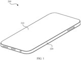
- FIG. 1 and FIG. 2 respectively show an overall three-dimensional structure and a planar structure of an electronic device.
- an electronic device 200 provided in this embodiment of this application may include at least a display 210, a middle frame 220, a circuit board 230, a battery 240, and a rear cover (not shown in the figure).
- the middle frame 220, the circuit board 230, and the battery 240 are located between the display 210 and the rear cover.
- the battery 240 may usually have an interface (not shown in the figure) of the battery 240, and the interface of the battery 240 is electrically connected to the circuit board 230.
- the circuit board 230 may be disposed on the middle frame 220.
- the circuit board 230 may be disposed on a surface of the middle frame 220 facing the rear cover, or the circuit board 230 may be disposed on a surface of the middle frame 220 facing the display 210.
- the battery 240 may be disposed on the surface of the middle frame 220 facing the rear cover, or the battery 240 may be disposed on the surface of the middle frame 220 facing the display 210.
- the surface of the middle frame 220 facing the rear cover may have a compartment (not shown in the figure) of the battery 240, and the battery 240 may be mounted in the compartment of the battery 240.
- the battery 240 may be connected to a charging management module and the circuit board 230 by using a power management module.
- the power management module receives an input of the battery 240 and/or an input of the charging management module, and supplies power to a processor, an internal memory, an external memory, the display 210, a camera module, a communication module, and the like.
- the power management module may be further configured to monitor parameters such as a capacity of the battery 240, a cycle count of the battery 240, and a state of health (leakage or impedance) of the battery 240.
- the power management module may alternatively be disposed in the processor of the circuit board 230.
- the power management module and the charging management module may alternatively be disposed in a same component.
- the display 210 may be an organic light-emitting diode (Organic Light-Emitting Diode, OLED) display 210, or may be a liquid crystal display (Liquid Crystal Display, LCD) 210.
- OLED Organic Light-Emitting Diode
- LCD Liquid Crystal Display
- the display 210 may be an OLED display 210.
- the middle frame 220 may include a middle plate 221 and a side frame 222, and the side frame 222 may be disposed around a periphery of the middle plate 221 for one circle.
- the side frame 222 may include a top edge, a bottom edge, a left edge, and a right edge, and the side frame 222 having a square ring structure is enclosed by the top edge, the bottom edge, the left edge, and the right edge.
- a material of the middle plate 221 may include but is not limited to an aluminum plate, an aluminum alloy, stainless steel, a steel-aluminum composite die-casting plate, a titanium alloy, or a magnesium alloy.
- the material of the middle plate 221 may be plastic or the like.
- the middle frame 220 is a relatively complex structure in actual product design. It is merely said that the middle frame 220 is usually spatially divided into the circumferential side frame 222 and the region middle plate 221 that needs to accommodate a main board, a sub-board, the battery 240, or the like. Therefore, distribution of a material of the middle frame 220 is not necessarily complete.
- the battery compartment is usually made of metal, but may alternatively be made of plastic only in consideration of impact of some other factors.
- the side frame 222 may be a metal side frame 222 or a plastic side frame 222, may be a ceramic side frame 222, or may be a glass side frame 222.
- a material of the metal side frame 222 may include but is not limited to an aluminum alloy, stainless steel, a steel-aluminum composite die-casting plate, a titanium alloy, or the like.
- the middle plate 221 may be connected to the side frame 222 through clamping, welding, bonding, or integral molding, or the middle plate 221 may be fixedly connected to the side frame 222 through injection molding.
- the rear cover may be a metal rear cover, may be a glass rear cover, may be a plastic rear cover, or may be a ceramic rear cover.
- a material of the rear cover is not limited, and the foregoing example imposes no limitation.
- the rear cover of the electronic device 200 may be connected to the side frame 222 to form a unibody (Unibody) rear cover.
- the electronic device 200 may include the display 210, the middle plate 221, and a battery cover.
- the battery cover may be the unibody (Unibody) rear cover formed by the side frame 222 and the rear cover. In this way, the circuit board 230 and the battery 240 are located in space enclosed by the middle plate 221 and the battery cover.
- the electronic device 200 may further include a USB interface 250, a card tray 260, and a motor 270.
- the USB interface 250, the card tray 260, and the motor 270 are usually disposed at a bottom end of the electronic device 200, namely, a location relatively close to the bottom edge of the side frame 222.
- the structure shown in this embodiment of this application constitutes no specific limitation on the electronic device 200.
- the electronic device 200 may include more or fewer parts than those shown in the figure, some parts may be combined, some parts may be split, or there may be different part arrangements.
- the electronic device 200 may further include components such as a camera (for example, a front-facing camera and a rear-facing camera) and a flash light.
- the electronic device 200 inevitably needs to implement an electrical connection in the electronic device 200 through structural design matching.
- a near field communication (Near Field Communication, NFC) technology-based coil module is connected to the circuit board 230 by elastically connecting a spring sheet.
- An antenna functional spring sheet on the circuit board 230 is connected to the middle frame 220 by riveting a metal member with the middle frame 220.
- the display 210 is connected to the middle frame 220 by using conductive foam and by welding a metal sheet.
- a metal structural member 110 is connected to the middle frame 220 by using a fastener 120.
- the metal structural member 110 has a first through hole 111
- the middle frame 220 has a second through hole 2201
- the fastener 120 passes through the first through hole 111 and the second through hole 2201 to fasten the metal structural member 110 and the middle frame 220.
- the metal structural member 110 is connected to the middle frame 220 and the circuit board 230 by using the fastener 120.
- the metal structural member 110 has the first through hole 111
- the middle frame 220 has the second through hole 2201
- the circuit board 230 has a third through hole 2301.
- the fastener 120 passes through the first through hole 111, the second through hole 2201, and the third through hole 2301 to fasten the metal structural member 110, the middle frame 220, and the circuit board 230.
- a gap is easily generated between the metal structural member 110 and the circuit board 230, which further causes poor contact between the metal structural member 110 and the circuit board 230 or between the circuit board 230 and the middle frame 220, resulting in poor use performance of the electronic device 200.
- an electrical connection location may usually be a region of the circuit board 230.
- a structural member, the circuit board 230, and the middle frame 220 may be locked together to implement an electrical connection.
- the structural member may be a metal structural member, to enhance contact between the structural member and the circuit board 230.
- the structural member may be a gasket welded below the circuit board 230, and in this case, the gasket serves as a metal structural member, to enhance contact between the gasket and the middle frame 220.
- a non-board sub-region namely, a region outside the circuit board 230
- a speaker component region there may be a situation in which a speaker component and the middle frame 220 are locked together.
- the speaker component is a metal-plastic composite structural member, and a metal part serves as the metal structural member in this embodiment of this application. Then, it is equivalent to enhancing reliability of a connection between the speaker component and the middle frame 220.
- a convex hull 116 (as shown in FIG. 5 and FIG. 6 ) is usually added between two contact surfaces (for example, between the metal structural member and the middle frame 220 or between the metal structural member and the circuit board 230) in actual design, to absorb a floating height when the fastener is fastened (for example, a screw is screwed) or a gap between contact surfaces.
- a structure of the convex hull 116 effectively improves impedance of the contact surface, mainly by changing surface contact to point contact, increasing a pressure of a contact point to destroy an interface of a non-good conductor, and increasing a nominal contact area. This reduces impedance, to form a more stable electrical connection.
- a height of the convex hull 116 needs to be 0.08 ⁇ 0.02 mm, and a distance from a center of the convex hull 116 to an edge of the contact surface is more than 0.6 mm on one side.
- the convex hull 116 is in a combination scenario of a screw and the convex hull 116, in some architectures, for example, when the structural member is in limited XY space (namely, not in a thickness direction of the electronic device 200), it is difficult to mold the complete convex hull 116, and it is impossible to ensure that the convex hull 116 has an enough effective contact area. If the sufficient contact area cannot be ensured, when the contact point enters a high resistance region, an uncontrollable electrical connection problem occurs in the point-to-surface contact, or even a fatal RSE regulatory issue is presented in a high current region.
- an embodiment of this application provides a new connection structure and an electronic device having the connection structure, and the connection structure is applied to the electronic device.
- the electronic device includes at least a middle frame, a metal structural member, and a fastener; the metal structural member has a first through hole, the middle frame has a second through hole, and the fastener passes through the first through hole and the second through hole, to fasten the metal structural member and the middle frame; at least one through groove is provided on the metal structural member, a surface of the through groove facing away from the middle frame is recessed, and the through groove extends to at least one outer edge of the metal structural member; and a surface of a groove bottom of the through groove facing the middle frame is protruded.
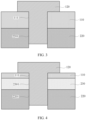
- the electronic device 200 may include at least a middle frame 220, a metal structural member 110, and a fastener 120.
- the metal structural member 110 has a first through hole 111
- the middle frame 220 has a second through hole 2201
- the fastener 120 passes through the first through hole 111 and the second through hole 2201, to fasten the metal structural member 110 and the middle frame 220.
- At least one through groove 112 is provided on the metal structural member 110, a surface of the through groove 112 facing away from the middle frame 220 is recessed, and a surface of the through groove 112 facing the middle frame 220 is protruded.
- the through groove 112 has a groove surface (namely, a groove surface 1121 of the through groove) and a groove bottom (namely, a groove bottom 1122 of the through groove), the groove surface 1121 of the through groove is recessed, and the groove bottom 1122 of the through groove is protruded.
- a region on a surface of the metal structural member 110 facing away from the middle frame 220 except the through groove 112 is a first flat surface S 1
- a region on a surface of the metal structural member 110 facing the middle frame 220 except the through groove 112 is a second flat surface S2.
- the groove surface 1121 of the through groove is recessed relative to the first flat surface S1
- the groove bottom 1122 of the through groove is protruded relative to the second flat surface S2.
- the through groove 112 may extend to at least one outer edge of the metal structural member 110.
- the through groove 112 may extend to one outer edge of the metal structural member 110, or the through groove 112 may extend to two outer edges of the metal structural member 110, or the through groove 112 may extend to three outer edges of the metal structural member 110.
- a specific disposing location of the through groove 112 is not limited in this embodiment of this application.
- a quantity of through grooves 112 may be one, two, three, or more. This is not limited in this embodiment of this application.
- the fastener 120 By passing the fastener 120 through the first through hole 111 on the metal structural member 110 and the second through hole 2201 on the middle frame 220, the fastener 120 can fixedly connect the metal structural member 110 and the middle frame 220.
- the at least one through groove 112 is provided on the metal structural member 110, and the surface of the groove bottom 1122 of the through groove facing the middle frame 220 is protruded, so that the groove bottom 1122 of the through groove can squeeze the middle frame 220, to absorb a gap between the metal structural member 110 and the middle frame 220. Therefore, existence of a gap between the metal structural member 110 and the middle frame 220 in scenarios such as falling can be avoided, and a problem of poor overall performance of the electronic device 200 due to poor contact between the metal structural member 110 and the middle frame 220 can be further avoided.
- the first through hole 111 may not be provided on the metal structural member 110, but the first through hole 111 is replaced with a blind hole (not shown in the figure).
- the fastener 120 passes through the second through hole 2201 on the middle frame, and an end of the fastener 120 abuts against an inner wall of the blind hole, to fasten the metal structural member 110 and the middle frame 220.
- a through hole for example, the second through hole 2201
- the blind hole is not provided.
- the metal structural member 110 may include a main body part 110b and at least one first connection part 110a. As shown in FIG. 11 , the metal structural member 110 includes the main body part 110b and three first connection parts 110a, and each first connection part 110a has the first through hole 111.
- the middle frame 220 may have a second connection part 2201a, and the second connection part 2201a has the second through hole 2201.
- connection structure 100 is applied to the electronic device 200.
- the connection structure 100 includes at least a first connection part 110a of a metal structural member 110, a second connection part 2201a of a middle frame 220, and a fastener 120.
- the fastener 120 passes through a first through hole 111 and a second through hole 2201, to fasten the first connection part 110a and the second connection part 2201a, to fixedly connect the metal structural member 110 and the middle frame 220.
- connection structure 100 at least one through groove 112 is provided on a surface of the first connection part 110a facing away from the second connection part 2201a, and a surface of the through groove 112 facing away from the second connection part 2201a is recessed.
- the through groove 112 extends to at least one outer edge of the first connection part 110a, and a surface of the through groove 112 facing the second connection part 2201a is protruded.
- the circuit board 230 is usually located between the metal structural member 110 and the middle frame 220.
- the at least one through groove 112 is located on a surface of the metal structural member 110 facing away from the circuit board 230, and a surface of a groove bottom 1122 of the through groove facing the circuit board 230 is protruded.
- the at least one through groove 112 is provided on the metal structural member 110, and the through groove 112 is also located on the surface of the metal structural member 110 facing away from the circuit board 230.
- the surface of the groove bottom 1122 of the through groove facing the circuit board 230 is protruded, so that the groove bottom 1122 of the through groove can squeeze the circuit board 230, to absorb a gap between the metal structural member 110 and the circuit board 230.
- the metal structural member 110 has the first through hole 111
- the middle frame 220 has the second through hole 2201
- the circuit board 230 has a third through hole 2301
- the fastener 120 passes through the first through hole 111, the second through hole 2201, and the third through hole 2301, to fasten the metal structural member 110, the middle frame 220, and the circuit board 230.
- the through groove 112 may be formed by using a stamping process.
- the stamping process has advantages of high production efficiency and low material consumption. Therefore, forming the through groove 112 on the metal structural member 110 by using the stamping process can improve efficiency of producing the through groove 112, and can fully utilize the metal structural member 110, thereby avoiding a waste of costs.
- the stamping process has relatively high size precision and relatively good processing stability.
- the through groove 112 can relatively well adapt to a structural feature, and has a relatively low requirement on a spatial size of the metal structural member 110.
- a size requirement of XY space can be reduced by replacing a conventional structure of the convex hull 116 with the through groove 112.
- the metal structural member 110 has no bent edge or only one side of the metal structural member 110 includes the bent edge, effective contact between the metal structural member 110 and the middle frame 220 or between the metal structural member 110 and the circuit board 230 can be implemented by designing symmetrical through grooves 112, and processing difficulty of the through groove 112 can also be reduced.
- the through groove 112 may be a U-shaped groove. Processing difficulty of the U-shaped groove is relatively low, and a process of forming the U-shaped groove by using the stamping process is relatively mature.
- the through groove 112 may be provided close to the first through hole 111.
- the fastener 120 needs to pass through the first through hole 111 to implement a connection between the metal structural member 110 and the middle frame 220.
- the through groove 112 is provided at a location close to the first through hole 111. Because the surface of the groove bottom 1122 of the through groove facing the middle frame 220 is protruded, at a location of the through groove 112 closer to the first through hole 111, the groove bottom 1122 of the through groove has a better squeezing effect when squeezing the middle frame 220. In this way, a gap between the metal structural member 110 and the middle frame 220 can be better absorbed, thereby avoiding, to a greater extent, a problem that there is a gap between the structural member and the circuit board 230 in scenarios such as falling.
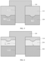
- At least one convex hull 116 may be disposed on the metal structural member 110 (refer to FIG. 8 or FIG. 30 ).
- a surface of the convex hull 116 facing the middle frame 220 is protruded, and a surface of the convex hull 116 facing away from the middle frame 220 is a flat surface.
- the convex hull 116 has a first surface (namely, a first surface 1161 of the convex hull) and a first surface (namely, a second surface 1162 of the convex hull), the first surface 1161 of the convex hull is protruded, and the second surface 1162 of the convex hull is a flat surface.
- a region on a surface of the metal structural member 110 facing away from the middle frame 220 except the through groove 112 and the convex hull 116 is a first flat surface S 1
- a region on a surface of the metal structural member 110 facing the middle frame 220 except the through groove 112 and the convex hull 116 is a second flat surface S2.
- the first surface 1161 of the convex hull is protruded relative to the second flat surface S2
- the second surface 1162 of the convex hull is the flat surface, that is, the second surface 1162 of the convex hull is located on a same plane as the first flat surface S 1.
- the at least one convex hull 116 is further disposed on the metal structural member 110.
- the convex hull 116 may be symmetrically disposed with the through groove 112, so that integral structure design of the metal structural member 110 can be as symmetrical as possible.
- the structure of the convex hull 116 can effectively improve impedance of a contact surface between the metal structural member 110 and the middle frame 220.
- adding the convex hull 116 can change surface contact between the metal structural member 110 and the middle frame 220 to point contact, thereby increasing a pressure of a contact point to destroy an interface of a non-good conductor, increasing a nominal contact area, and reducing impedance. Therefore, by adding the convex hull 116 on a basis of providing the through groove 112 on the surface of the metal structural member 110 facing the middle frame 220, a more stable electrical connection can be formed between the metal structural member 110 and the middle frame 220.
- the convex hull 116 may not be disposed on the metal structural member 110 (as shown in FIG. 7 ). This is not limited in this embodiment of this application, and is not limited to the foregoing example.
- the convex hull 116 may be disposed close to the first through hole 111.
- the convex hull 116 is disposed at a location close to the first through hole 111. Because the surface of the convex hull 116 facing the middle frame 220 is protruded, the convex hull 116 can effectively improve impedance of a contact surface between the metal structural member 110 and the middle frame 220. At a location of the convex hull 116 closer to the first through hole 111, the convex hull 116 has a better squeezing effect when squeezing the middle frame 220.
- a gap between the metal structural member 110 and the middle frame 220 can be better absorbed, thereby avoiding, to a greater extent, a problem that there is a gap between the structural member and the circuit board 230 in scenarios such as falling, and forming a more stable electrical connection between the metal structural member 110 and the middle frame 220.
- the convex hull 116 and the through groove 112 may be used together.
- a spatial size can be applied more flexibly, and a contact balance can be ensured as much as possible, a quantity and an area of contact points can be increased, and a risk of a contact failure after a reliability scenario is reduced.
- the combination design of the through groove 112 and the convex hull 116 is used.
- Each contact point is equivalent to connecting one more resistor in parallel, and a resistance value decreases exponentially, helping further reduce system impedance.
- impedance of a single convex hull 116 is approximately 200 m ⁇ .
- the battery 240 group usually requires impedance less than 40 m ⁇ . In this case, a plurality of points need to be connected in parallel, to further reduce system impedance.
- the electronic device 200 includes the circuit board 230.
- the convex hull 116 and the through groove 112 need to be evenly arranged.
- contact between the metal structural member 110 and the circuit board 230 can be increased by using the convex hull 116 or the through groove 112.
- contact between the metal structural member 110 and the circuit board 230 can be increased by using the through groove 112.
- the convex hull 116 and the through groove 112 facing the circuit board 230 may be protruded by 0.05 mm relative to the second flat surface S2 of the metal structural member 110, and a protruding contact area may be approximately 0.2 mm 2 . It should be noted that a specific area is not limited in this embodiment of this application, and is not limited to the foregoing example.
- the convex hull 116 is usually a ball-head convex hull, a nominal contact surface of point contact of the ball-head convex hull is annular, and a length of the annular contact surface in each direction is consistent. If a diameter of the ball-head convex hull is large, a problem of a contact failure can be resolved to some extent. However, because of an increase in a size in each direction, more space is lost.
- a nominal contact surface of the through groove 112 is a rectangle, and may be relatively long in a single direction without affecting a design size of another edge.
- the through groove 112 does not need to reserve a skirt edge (that is, there is no edge location around the through groove 112), so that a size of the metal structural member 110 can be further reduced.
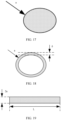
- a is a radius of a contact surface between the convex hull 116 and the middle frame 220
- R is a radius of the convex hull 116
- 2a' and L are separately a characteristic side length of the through groove 112.
- the contact surface between the convex hull 116 and the middle frame 220 is in a shape of a circle.
- the contact surface between the convex hull 116 and the middle frame 220 is in a shape of a circular ring.
- the contact surface between the through groove 112 and the middle frame 220 is in a shape of a rectangle.
- the contact surface between the convex hull 116 and the middle frame 220 is in a shape of a square ring.
- the convex hull is a ball-head convex hull.
- the convex hull 116 interferes 0.08 mm
- a percentage of the convex hull 116 to the through groove 112 is 78.5%. Therefore, the through groove 112 is designed with a larger nominal contact area and an effect is better.
- the through groove 112 may be designed at a non-bent edge location. This can reduce molding difficulty of the through groove 112, ensure a size of the metal structural member 110, and reduce processing costs.
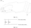
- an end of the first connection part 110a of the metal structural member 110 has a bent edge 113, and an extension direction L1 of the through groove may be perpendicular to a length direction L2 of the bent edge.
- the through groove 112 may be molded at a location perpendicular to the bent edge 113. In this case, a distance usually needs to be reserved between the through groove 112 and the bent edge 113, to prevent the bent edge 113 from interfering with the through groove 112.
- a first through groove 112a and a second through groove 112b are molded at the location perpendicular to the bent edge 113, a surface of a groove surface 1121a of the first through groove facing away from the middle frame 220 and a surface of a groove surface 1121b of the second through groove facing away from the middle frame 220 are recessed, and a surface of a groove bottom 1122a of the first through groove facing the middle frame 220 and a surface of a groove bottom 1122b of the second through groove facing the middle frame 220 are protruded.
- the extension direction L1 of the through groove may be parallel to the length direction L2 of the bent edge.
- the extension direction L1 of the through groove By designing the extension direction L1 of the through groove to be parallel to the length direction L2 of the bent edge, the bent edge 113 of the metal structural member 110 is not damaged when the through groove 112 is produced, for example, when stamping molding is performed on the through groove 112.
- the extension direction L1 of the through groove is parallel to the length direction L2 of the bent edge, so that the bent edge 113 of the metal structural member 110 does not interfere with a process of producing the through groove 112, thereby preventing existence of the bent edge 113 from affecting stability and reliability of the process of producing the through groove 112.
- two symmetrical through grooves 112 may be molded at a location parallel to the bent edge 113, and the two through grooves 112 may be molded at one time.
- a third through groove 112c and a fourth through groove 112d that are symmetrical to each other are molded at the location parallel to the bent edge 113, a surface of a groove surface 1121c of the third through groove facing away from the middle frame 220 and a surface of a groove surface 1121 d of the fourth through groove facing away from the middle frame 220 are recessed, and a surface of a groove bottom 1122c of the third through groove facing the middle frame 220 and a surface of a groove bottom 1122d of the fourth through groove facing the middle frame 220 are protruded.
- one through groove 112 may be molded at the location parallel to the bent edge 113, and the through groove 112 may also be molded at one time.
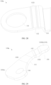
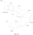
- the metal structural member 110 may have a notch 114, and the notch 114 may be in communication with the first through hole 111, so that at least one elastic arm 115 is formed on the metal structural member 110 (refer to FIG. 29 and FIG. 31 ).
- the metal structural member 110 implements disconnection design. Because the metal structural member 110 has the first through hole 111, and the notch 114 is in communication with the first through hole 111, at least one end of the metal structural member 110 is suspended, and the end designed to be suspended has relative elasticity, thereby ensuring that the at least one elastic arm 115 is formed on the metal structural member 110.
- the metal structural member 110 may have a notch 114, and the notch 114 is in communication with the first through hole 111.
- the metal structural member 110 may not have the elastic arm 115.
- the metal structural member 110 without the elastic arm 115 has a relatively poor effect on absorbing a gap between the metal structural member 110 and the circuit board 230.
- a screw floating height of about 0.08 mm can be absorbed, but an actual floating height may far exceed this height.
- a screw has a floating height of about 0.15 mm.
- the metal structural member 110 needs to have an elastic force greater than 0.7 N when the metal structural member 110 is at a working height of 0.35 mm. Therefore, the elastic arm 115 needs to be added to an original closed metal structural member 110. This design can ensure that the metal structural member 110 is used at a location at which a radio frequency current is relatively high, at an ESD sensitive location, or in a scenario in which impedance before and after environment reliability is strictly required, to ensure that a function does not fail.
- an application scenario of the metal structural member 110 is not limited to a screw locking scenario only.
- the through groove 112 (for example, a U-shaped groove) may also be used to improve contact reliability.
- a feature of the through groove 112 may be provided on the elastic arm 115, or may be provided at a location outside the elastic arm 115 (namely, a region location on the metal structural member 110 outside the elastic arm 115).
- the extension direction L1 of the through groove is not specially limited, and the through groove 112 may usually follow a radius direction of an inner circle of the metal structural member 110.
- one elastic arm 115 is formed on the metal structural member 110, and the through groove 112 may be located on the elastic arm 115.
- the through groove 112 can further squeeze and absorb a gap between the metal structural member 110 and the middle frame 220.
- the through groove 112 may alternatively be located in a region on the metal structural member 110 outside the elastic arm 115. In this case, the through groove 112 can also further squeeze and absorb a gap between the metal structural member 110 and the middle frame 220 on a basis of the elastic arm 115.
- the through groove 112 when the through groove 112 is provided on the metal structural member 110, regardless of whether the through groove 112 is provided on the elastic arm 115 or the through groove 112 is provided in the region on the metal structural member 110 except the elastic arm 115, as long as the surface of the groove bottom 1122 of the through groove facing the middle frame 220 is protruded, the groove bottom 1122 of the through groove can squeeze the middle frame 220, so that a gap between the metal structural member 110 and the middle frame 220 can be well absorbed, thereby avoiding, to a great extent, a problem that there is a gap between the structural member and the circuit board 230 in scenarios such as falling.
- a structure of the metal structural member 110 includes but is not limited to the following several possible implementations:
- the metal structural member 110 may include a first part 1101, the first part 1101 has a first end and a second end (namely, a first end 1101a of the first part and a second end 1101b of the first part) that are opposite to each other, and the second end 1101b of the first part serves as the elastic arm 115.
- a metal structural member 110 having one elastic arm 115 forms a two-claw metal structural member 110.
- the metal structural member 110 is the two-claw metal structural member 110, and the through groove 112 is located on the elastic arm 115.
- the metal structural member 110 is the two-claw metal structural member 110, and the through groove 112 is located in a region on the two-claw metal structural member 110 outside the elastic arm 115.
- the metal structural member 110 has one through groove 112 and one convex hull 116.
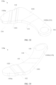
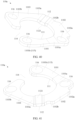
- the metal structural member 110 includes the first part 1101 and a second part 1102, the second part 1102 has a first end and a second end (namely, a first end 1102a of the second part and a second end 1102b of the second part) that are opposite to each other, the second end 1101b of the first part serves as the elastic arm 115, and the first end 1102a of the second part is connected to the first end 1101a of the first part.
- the first end 1102a of the second part is connected to the first end 1101a of the first part, and a metal structural member 110 having one elastic arm 115 forms a three-claw metal structural member 110.
- the metal structural member 110 is the three-claw metal structural member 110, and the through groove 112 is located on the elastic arm 115.
- the metal structural member 110 is the three-claw metal structural member 110, and the through groove 112 is located in a region on the three-claw metal structural member 110 outside the elastic arm 115.
- the metal structural member 110 has one through groove 112 and two convex hulls 116.
- the metal structural member 110 includes the first part 1101, the second part 1102, and a third part 1103, the third part 1103 has a first end and a second end (namely, a first end 1103a of the third part and a second end 1103b of the third part) that are opposite to each other, and the second end 1101b of the first part serves as the elastic arm 115.
- the first end 1102a of the second part is connected to the first end 1101a of the first part
- the second end 1102b of the second part is connected to the first end 1103a of the third part
- a metal structural member 110 having one elastic arm 115 forms a four-claw metal structural member 110.
- the metal structural member 110 is the four-claw metal structural member 110, and the through groove 112 is located on the elastic arm 115.
- the metal structural member 110 is the four-claw metal structural member 110, and the through groove 112 is located in a region on the four-claw metal structural member 110 outside the elastic arm 115.
- the metal structural member 110 has one through groove 112 and three convex hulls 116.
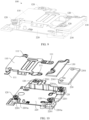
- the metal structural member 110 is not limited to layouts shown in FIG. 9 and FIG. 10 , provided that the metal structural member 110 is a layer of multi-layer contact, and the contact surface is not limited.
- the metal structural member 110 may be a metal structural member 110; or may not be limited to a structural member of metal, and may be replaced by any material to implement effective contact between the two. It does not necessarily have to be for a purpose of a conduction relationship, and reliable contact of a structure itself can also be beneficial.
- connection structure 100 may further include a plastic structural member 130.
- the plastic structural member 130 is connected to the first connection part 110a of the metal structural member 110 by using the fastener 120.
- the fastener 120 may be a structure such as a screw, a stud, or a bolt. This is not limited in this embodiment of this application, and is not limited to the foregoing example.
- a location at which the plastic structural member 130 is combined with the metal structural member 110 may be a location at which the fastener 120 is located, or may be a location except the fastener 120.
- the plastic structural member 130 and the fastener 120 may be molded integrally before locking the fastener 120 on the metal structural member 110. Therefore, a layout of the fastener 120 is not a key condition that affects a combination location of the plastic structural member 130 and the metal structural member 110.
- the plastic structural member 130 and the metal structural member 110 may be molded by injection, to further ensure connection reliability between the metal structural member 110 and the middle frame 220 or between the metal structural member 110 and the circuit board 230.
- injection molding of the plastic structural member 130 and the metal structural member 110 can also improve the overall reliability of the plastic structural member 130 and the metal structural member 110 to some extent.
- the plastic structural member 130 can provide an insulation or isolation effect at some locations.
- the terms “mount”, “communicate”, and “connect” should be understood in a broadest sense, for example, may be a fixed connection, an indirect connection by using an intermediate medium, or communication inside two elements or an interactive relationship between two elements.
- the terms “mount”, “communicate”, and “connect” should be understood in a broadest sense, for example, may be a fixed connection, an indirect connection by using an intermediate medium, or communication inside two elements or an interactive relationship between two elements.
- a process, a method, a system, a product, or a device that includes a series of steps or units is not necessarily limited to those steps or units that are clearly listed, but may include other steps or units that are not clearly listed or are inherent to the process, the method, the product, or the device.
Landscapes
- Engineering & Computer Science (AREA)
- Theoretical Computer Science (AREA)
- Computer Hardware Design (AREA)
- Physics & Mathematics (AREA)
- General Engineering & Computer Science (AREA)
- Human Computer Interaction (AREA)
- General Physics & Mathematics (AREA)
- Signal Processing (AREA)
- Power Engineering (AREA)
- Electromagnetism (AREA)
- Microelectronics & Electronic Packaging (AREA)
- Casings For Electric Apparatus (AREA)
Abstract
Description
- This application claims priority to
Chinese Patent Application No. 202211511521.4, filed with the China National Intellectual Property Administration on November 29, 2022 Chinese Patent Application No. 202310204554.2, filed with the China National Intellectual Property Administration on February 24, 2023 - Embodiments of this application relate to the field of terminal technologies, and in particular, to a connection structure and an electronic device.
- Currently, electronic devices such as computers and mobile phones have become inseparable from our lives, are seen everywhere in our lives, and greatly improve living standards of people.
- To implement a function required by a user, it is usually necessary to implement an electrical connection in the electronic device through structural design matching. For example, a near field communication (Near Field Communication, NFC) technology-based coil module is electrically connected to a circuit board by elastically connecting a spring sheet. An antenna functional spring sheet on the circuit board is electrically connected to a middle frame by riveting a metal member. A display is electrically connected to the middle frame by welding a metal sheet and by using conductive foam. In many electrical connection solutions, it is a common way to implement an electrical connection between a plurality of structural members by using a screw connection.
- However, in a process in which the user uses the electronic device, because of scenarios such as falling, a gap is easily generated between the structural member and the circuit board, which further causes poor contact between the structural member and the circuit board or between the circuit board and the middle frame, resulting in poor performance of the electronic device.
- Embodiments of this application provide a connection structure and an electronic device, which can avoid existence of a gap between a metal structural member and a circuit board in scenarios such as falling, and can further avoid a problem of poor overall performance due to poor contact between the metal structural member and the circuit board or between the circuit board and a middle frame.
- According to a first aspect, an embodiment of this application provides an electronic device. The electronic device includes at least a middle frame, a metal structural member, and a fastener; the metal structural member has a first through hole, the middle frame has a second through hole, and the fastener passes through the first through hole and the second through hole; at least one through groove is provided on the metal structural member, a surface of the through groove facing away from the middle frame is recessed, and the through groove extends to at least one outer edge of the metal structural member; and a surface of the through groove facing the middle frame is protruded.
- According to the electronic device provided in this embodiment of this application, the fastener can fixedly connect the metal structural member and the middle frame by passing the fastener through the first through hole on the metal structural member and the second through hole on the middle frame. In addition, the at least one through groove is provided on the metal structural member, the surface of the through groove facing away from the middle frame is recessed, the through groove extends to the at least one outer edge of the metal structural member, and the surface of the through groove facing the middle frame is protruded. In this way, the through groove can squeeze the middle frame, to absorb a gap between the metal structural member and the middle frame. Therefore, existence of a gap between the metal structural member and the middle frame in scenarios such as falling can be avoided, and a problem of poor overall performance of the electronic device due to poor contact between the metal structural member and the middle frame can be further avoided.
- In a possible implementation, the through groove is formed by using a stamping process. The stamping process has advantages of high production efficiency and low material consumption. Therefore, forming the through groove on the metal structural member by using the stamping process can improve efficiency of producing the through groove, and can fully utilize the metal structural member, thereby avoiding a waste of costs. In addition, the stamping process has relatively high size precision and relatively good processing stability.
- In a possible implementation, the through groove is provided close to the first through hole. The through groove is provided at a location close to the first through hole. Because the surface of the through groove facing the middle frame is protruded, at a location of the through groove closer to the first through hole, a groove bottom of the through groove has a better squeezing effect when squeezing the middle frame. In this way, a gap between the metal structural member and the middle frame can be better absorbed, thereby avoiding, to a greater extent, a problem that there is a gap between the metal structural member and the middle frame in scenarios such as falling.
- In a possible implementation, a contact surface between the through groove and the middle frame is in a shape of a rectangle or a square ring.
- In a possible implementation, at least one convex hull is further disposed on the metal structural member. The at least one convex hull is further disposed on the metal structural member, and a structure of the convex hull can effectively improve impedance of a contact surface between the metal structural member and the middle frame. Specifically, adding the convex hull can change surface contact between the metal structural member and the middle frame to point contact, thereby increasing a pressure of a contact point to destroy an interface of a non-good conductor, increasing a nominal contact area, and reducing impedance. Therefore, by adding the convex hull on a basis of providing the through groove on the metal structural member, a more stable electrical connection can be formed between the metal structural member and the middle frame.
- In a possible implementation, a surface of the convex hull facing the middle frame is protruded and a surface of the convex hull facing away from the middle frame is a flat surface.
- In a possible implementation, the convex hull is disposed close to the first through hole. The convex hull is disposed at a location close to the first through hole. Because the surface of the convex hull facing the middle frame is protruded, the convex hull can effectively improve impedance of a contact surface between the metal structural member and the middle frame. At a location of the convex hull closer to the first through hole, the convex hull has a better squeezing effect when squeezing the middle frame. In this way, a gap between the metal structural member and the middle frame can be better absorbed, thereby avoiding, to a greater extent, a problem that there is a gap between the metal structural member and the middle frame in scenarios such as falling, and forming a more stable electrical connection between the metal structural member and the middle frame.
- In a possible implementation, a contact surface between the convex hull and the middle frame is in a shape of a circle or a circular ring.
- In a possible implementation, an end of the metal structural member has a bent edge; and an extension direction of the through groove is parallel to a length direction of the bent edge. By designing the extension direction of the through groove to be parallel to the length direction of the bent edge, the bent edge of the metal structural member is not damaged when the through groove is produced. In addition, the extension direction of the through groove is parallel to the length direction of the bent edge, so that the bent edge of the metal structural member does not interfere with a process of producing the through groove, thereby preventing existence of the bent edge from affecting stability and reliability of the process of producing the through groove.
- In a possible implementation, the metal structural member has a notch and the notch is in communication with the first through hole, so that at least one elastic arm is formed on the metal structural member. By providing the notch on the metal structural member, the metal structural member implements disconnection design. Because the metal structural member has the first through hole, and the notch is in communication with the first through hole, at least one end of the metal structural member is suspended, and the end designed to be suspended has relative elasticity, thereby ensuring that the at least one elastic arm is formed on the metal structural member.
- In a possible implementation, one of the elastic arm is formed on the metal structural member; and the through groove is located on the elastic arm; or the through groove is located in a region on the metal structural member outside the elastic arm. When the through groove is provided on the metal structural member, regardless of whether the through groove is provided on the elastic arm or the through groove is provided in the region on the metal structural member except the elastic arm, as long as the surface of the through groove facing the middle frame is protruded, the groove bottom of the through groove can squeeze the middle frame, so that a gap between the metal structural member and the middle frame can be well absorbed, thereby avoiding, to a great extent, a problem that there is a gap between the metal structural member and the middle frame in scenarios such as falling.
- In a possible implementation, the metal structural member includes a first part; and the first part has a first end and a second end that are opposite to each other, and the second end serves as the elastic arm. In this case, a metal structural member having one elastic arm forms a two-claw metal structural member.
- In a possible implementation, the metal structural member further includes a second part; and one end of the second part is connected to the first end of the first part. In this case, the end of the second part is connected to the first end of the first part, and a metal structural member having one elastic arm forms a three-claw metal structural member.
- In a possible implementation, the metal structural member further includes a third part; and the other end of the second part is connected to the third part. In this case, the end of the second part is connected to the first end of the first part, the other end of the second part is connected to an end of the third part, and a metal structural member having one elastic arm forms a four-claw metal structural member.
- In a possible implementation, the electronic device further includes a circuit board, the circuit board is located between the metal structural member and the middle frame; and the at least one through groove is located on a surface of the metal structural member facing away from the circuit board, and a surface of the through groove facing the circuit board is protruded.
- When there is the circuit board between the metal structural member and the middle frame, the at least one through groove is provided on the metal structural member, and the through groove is also located on the surface of the metal structural member facing away from the circuit board. In this case, the surface of the through groove facing the circuit board is protruded, and the groove bottom of the through groove can squeeze the circuit board, to absorb a gap between the metal structural member and the circuit board. Therefore, existence of a gap between the metal structural member and the circuit board in scenarios such as falling can be avoided, and a problem of poor overall performance of the electronic device due to poor contact between the metal structural member and the circuit board or between the circuit board and the middle frame can be further avoided.
- According to a second aspect, an embodiment of this application provides a connection structure, applied to an electronic device. The electronic device includes a middle frame and a metal structural member, the metal structural member has a first connection part, and the middle frame has a second connection part; the connection structure includes at least the first connection part, the second connection part, and a fastener; and the first connection part has a first through hole, the second connection part has a second through hole, and the fastener passes through the first through hole and the second through hole; and
at least one through groove is provided on the first connection part, a surface of the through groove facing away from the second connection part is recessed, and the through groove extends to at least one outer edge of the first connection part; and a surface of the through groove facing the second connection part is protruded. - According to the connection structure provided in this embodiment of this application, the connection structure includes the first connection part of the metal structural member, the second connection part of the middle frame, and the fastener. By passing the fastener through the first through hole on the first connection part and the second through hole on the second connection part, the fastener can fixedly connect the first connection part and the second connection part, so that the metal structural member and the middle frame are fixedly connected. In addition, the at least one through groove is provided on the first connection part of the metal structural member, the surface of the through groove facing away from the second connection part of the middle frame is recessed, and the surface of the through groove facing the second connection part of the middle frame is protruded, so that a groove bottom of the through groove can squeeze the middle frame, to absorb a gap between the metal structural member and the middle frame. Therefore, existence of a gap between the metal structural member and the middle frame in scenarios such as falling can be avoided, and a problem of poor overall performance of the electronic device due to poor contact between the metal structural member and the middle frame can be further avoided.
- In a possible implementation, the through groove is formed by using a stamping process. The stamping process has advantages of high production efficiency and low material consumption. Therefore, forming the through groove on the metal structural member by using the stamping process can improve efficiency of producing the through groove, and can fully utilize the metal structural member, thereby avoiding a waste of costs. In addition, the stamping process has relatively high size precision and relatively good processing stability.
- In a possible implementation, the through groove is provided close to the first through hole. The through groove is provided at a location close to the first through hole. Because the surface of the through groove facing the middle frame is protruded, at a location of the through groove closer to the first through hole, the groove bottom of the through groove has a better squeezing effect when squeezing the middle frame. In this way, a gap between the metal structural member and the middle frame can be better absorbed, thereby avoiding, to a greater extent, a problem that there is a gap between the metal structural member and the middle frame in scenarios such as falling.
- In a possible implementation, at least one convex hull is further disposed on the first connection part. A structure of the convex hull can effectively improve impedance of a contact surface between the metal structural member and the middle frame. Specifically, adding the convex hull can change surface contact between the metal structural member and the middle frame to point contact, thereby increasing a pressure of a contact point to destroy an interface of a non-good conductor, increasing a nominal contact area, and reducing impedance. Therefore, by adding the convex hull on a basis of providing the through groove on the metal structural member, a more stable electrical connection can be formed between the metal structural member and the middle frame.
- In a possible implementation, the surface of the convex hull facing the second connection part is protruded, and a surface of the convex hull facing away from the second connection part is a flat surface.
- In a possible implementation, the convex hull is disposed close to the first through hole. Because the surface of the convex hull facing the middle frame is protruded, the convex hull can effectively improve impedance of a contact surface between the metal structural member and the middle frame. At a location of the convex hull closer to the first through hole, the convex hull has a better squeezing effect when squeezing the middle frame. In this way, a gap between the metal structural member and the middle frame can be better absorbed, thereby avoiding, to a greater extent, a problem that there is a gap between the metal structural member and the middle frame in scenarios such as falling, and forming a more stable electrical connection between the metal structural member and the middle frame.
- In a possible implementation, an end of the first connection part has a bent edge; and an extension direction of the through groove is parallel to a length direction of the bent edge. By designing the extension direction of the through groove to be parallel to the length direction of the bent edge, the bent edge of the metal structural member is not damaged when the through groove is produced. In addition, the extension direction of the through groove is parallel to the length direction of the bent edge, so that the bent edge of the metal structural member does not interfere with a process of producing the through groove, thereby preventing existence of the bent edge from affecting stability and reliability of the process of producing the through groove.
- In a possible implementation, the first connection part has a notch, and the notch is in communication with the first through hole, so that at least one elastic arm is formed on the first connection part; and the through groove is located on the elastic arm; or the through groove is located in a region on the first connection part outside the elastic arm. By providing the notch on the first connection part of the metal structural member, the first connection part implements disconnection design. Because the first connection part has the first through hole, and the notch is in communication with the first through hole, at least one end of the first connection part is suspended, and the end designed to be suspended has relative elasticity, thereby ensuring that the at least one elastic arm is formed on the first connection part.
- In addition, when the through groove is provided on the first connection part, regardless of whether the through groove is provided on the elastic arm or the through groove is provided in the region on the metal structural member except the elastic arm, as long as the surface of the through groove facing the middle frame is protruded, the groove bottom of the through groove can squeeze the middle frame, so that a gap between the metal structural member and the middle frame can be well absorbed, thereby avoiding, to a great extent, a problem that there is a gap between the metal structural member and the middle frame in scenarios such as falling.
-
-
FIG. 1 is a schematic diagram of a three-dimensional structure of an electronic device according to an embodiment of this application; -
FIG. 2 is a schematic diagram of a planar structure of an electronic device according to an embodiment of this application; -
FIG. 3 is a schematic diagram of a cross section of a connection structure in an electronic device in the conventional technology; -
FIG. 4 is a schematic diagram of another cross section of a connection structure in an electronic device in the conventional technology; -
FIG. 5 is a schematic diagram of still another cross section of a connection structure in an electronic device in the conventional technology; -
FIG. 6 is a schematic diagram of yet another cross section of a connection structure in an electronic device in the conventional technology; -
FIG. 7 is a schematic diagram of a cross section of a connection structure in an electronic device according to an embodiment of this application; -
FIG. 8 is a schematic diagram of a cross section of a connection structure in an electronic device according to an embodiment of this application; -
FIG. 9 is a schematic diagram of a three-dimensional structure of a connection structure in an electronic device according to an embodiment of this application; -
FIG. 10 is an exploded view ofFIG. 9 ; -
FIG. 11 is a schematic diagram of a three-dimensional structure of a connection structure in an electronic device according to an embodiment of this application; -
FIG. 12 is a schematic diagram of a front three-dimensional structure of a connection part in the connection structure shown inFIG. 11 ; -
FIG. 13 is a schematic diagram of a rear three-dimensional structure of a connection part in the connection structure shown inFIG. 11 ; -
FIG. 14 is a schematic diagram of a principle of a connection structure in contact with a middle frame or a circuit board according to an embodiment of this application; -
FIG. 15 is a schematic diagram of a structure when a convex hull in a connection structure is in contact with a middle frame or a circuit board according to an embodiment of this application; -
FIG. 16 is a schematic diagram of a structure when a through groove in a connection structure is in contact with a middle frame or a circuit board according to an embodiment of this application; -
FIG. 17 is a schematic diagram of a structure when a convex hull in a connection structure is in contact with a middle frame or a circuit board according to an embodiment of this application; -
FIG. 18 is a schematic diagram of a structure when a convex hull in a connection structure is in contact with a middle frame or a circuit board according to an embodiment of this application; -
FIG. 19 is a schematic diagram of a structure when a through groove in a connection structure is in contact with a middle frame or a circuit board according to an embodiment of this application; -
FIG. 20 is a schematic diagram of a structure when a through groove in a connection structure is in contact with a middle frame or a circuit board according to an embodiment of this application; -
FIG. 21 is a schematic diagram of a front three-dimensional structure of another connection part in the connection structure shown inFIG. 11 ; -
FIG. 22 is a schematic diagram of a rear three-dimensional structure of another connection part in the connection structure shown inFIG. 11 ; -
FIG. 23 is a schematic diagram of a three-dimensional structure of a connection structure in an electronic device according to an embodiment of this application; -
FIG. 24 is a schematic diagram of a front three-dimensional structure of a connection part in the connection structure shown inFIG. 23 ; -
FIG. 25 is a schematic diagram of a rear three-dimensional structure of a connection part in the connection structure shown inFIG. 23 ; -
FIG. 26 is a schematic diagram of a three-dimensional structure of a connection structure in an electronic device according to an embodiment of this application; -
FIG. 27 is a schematic diagram of a front three-dimensional structure of a connection part in the connection structure shown inFIG. 26 ; -
FIG. 28 is a schematic diagram of a rear three-dimensional structure of a connection part in the connection structure shown inFIG. 26 ; -
FIG. 29 is a schematic diagram of a front three-dimensional structure in which a through groove is located on an elastic arm when a connection part in a connection structure is a two-claw structure according to an embodiment of this application; -
FIG. 30 is a schematic diagram of a side three-dimensional structure in which a through groove is located on an elastic arm when a connection part in a connection structure is a two-claw structure according to an embodiment of this application; -
FIG. 31 is a schematic diagram of a rear three-dimensional structure in which a through groove is located on an elastic arm when a connection part in a connection structure is a two-claw structure according to an embodiment of this application; -
FIG. 32 is a schematic diagram of a front three-dimensional structure in which a through groove is located outside an elastic arm when a connection part in a connection structure is a two-claw structure according to an embodiment of this application; -
FIG. 33 is a schematic diagram of a rear three-dimensional structure in which a through groove is located outside an elastic arm when a connection part in a connection structure is a two-claw structure according to an embodiment of this application; -
FIG. 34 is a schematic diagram of a front three-dimensional structure in which a through groove is located on an elastic arm when a connection part in a connection structure is a three-claw structure according to an embodiment of this application; -
FIG. 35 is a schematic diagram of a rear three-dimensional structure in which a through groove is located on an elastic arm when a connection part in a connection structure is a three-claw structure according to an embodiment of this application; -
FIG. 36 is a schematic diagram of a front three-dimensional structure in which a through groove is located outside an elastic arm when a connection part in a connection structure is a three-claw structure according to an embodiment of this application; -
FIG. 37 is a schematic diagram of a rear three-dimensional structure in which a through groove is located outside an elastic arm when a connection part in a connection structure is a three-claw structure according to an embodiment of this application; -
FIG. 38 is a schematic diagram of a front three-dimensional structure in which a through groove is located on an elastic arm when a connection part in a connection structure is a four-claw structure according to an embodiment of this application; -
FIG. 39 is a schematic diagram of a rear three-dimensional structure in which a through groove is located on an elastic arm when a connection part in a connection structure is a four-claw structure according to an embodiment of this application; -
FIG. 40 is a schematic diagram of a front three-dimensional structure in which a through groove is located outside an elastic arm when a connection part in a connection structure is a four-claw structure according to an embodiment of this application; and -
FIG. 41 is a schematic diagram of a rear three-dimensional structure in which a through groove is located outside an elastic arm when a connection part in a connection structure is a four-claw structure according to an embodiment of this application. -
- 100-connection structure; 110-metal structural member; 110a-first connection part;
- 110b-main body part; 111-first through hole; 112-through groove;
- 1121-groove surface of a through groove; 1122-groove bottom of the through groove; 112a-first through groove;
- 1121a-groove surface of the first through groove; 1122a-groove bottom of the first through groove; 112b-second through groove;
- 1121b-groove surface of the second through groove; 1122b-groove bottom of the second through groove; 112c-third through groove;
- 1121c-groove surface of the third through groove; 1122c-groove bottom of the third through groove; 112d-fourth through groove;
- 1121d-groove surface of the fourth through groove; 1122d-groove bottom of the fourth through groove; 113-bent edge;
- 114-notch; 115-elastic arm; 1101-first part;
- 1 101a-first end of the first part; 1101b-second end of the first part; 1102-second part;
- 1102a-first end of the second part; 1102b-second end of the second part; 1103-third part;
- 1103a-first end of the third part; 1103b-second end of the third part; 116-convex hull;
- 1161-first surface of the convex hull; 1162-second surface of the convex hull; 120-fastener;
- 130-plastic structural member; 200-electronic device; 210-display;
- 220-middle frame; 221-middle plate; 222-side frame;
- 2201-second through hole; 2201a-second connection part; 230-circuit board;
- 2301-third through hole; 240-battery; 250-USB interface;
- 260-card tray; 270-motor; L1-extension direction of the through groove;
- L2-length direction of the bent edge; S 1-first flat surface; S2-second flat surface.
- Terms used in the implementation part of this application are merely intended to explain specific embodiments of this application, and are not intended to limit this application. Implementations of the embodiments of this application are described in detail below with reference to the accompanying drawings.
- Electronic devices such as computers and mobile phones have become inseparable from our lives, are seen everywhere in our lives, and greatly improve living standards of people.
- An embodiment of this application provides an electronic device, and the electronic device may include, but is not limited to, a mobile or fixed terminal that has a connection structure or requires an electrical connection, for example, a mobile phone, a tablet computer, a notebook computer, an ultra-mobile personal computer (ultra-mobile personal computer, UMPC), a handheld computer, a walkie-talkie, a netbook, a point of sales (Point of sales, POS), a personal digital assistant (personal digital assistant, PDA), a wearable device, a virtual reality device, a wireless USB flash drive, a Bluetooth speaker/headset, a factory-installed vehicle component, an event data recorder, or a security device.
- An example in which the foregoing electronic device is a mobile phone is used for description. The mobile phone provided in this embodiment of this application may be a curved-screen mobile phone or a flat-screen mobile phone. In this embodiment of this application, the flat-screen mobile phone is used as an example for description.
FIG. 1 andFIG. 2 respectively show an overall three-dimensional structure and a planar structure of an electronic device. Referring toFIG. 1 andFIG. 2 , anelectronic device 200 provided in this embodiment of this application may include at least adisplay 210, amiddle frame 220, acircuit board 230, abattery 240, and a rear cover (not shown in the figure). Themiddle frame 220, thecircuit board 230, and thebattery 240 are located between thedisplay 210 and the rear cover. Thebattery 240 may usually have an interface (not shown in the figure) of thebattery 240, and the interface of thebattery 240 is electrically connected to thecircuit board 230. - The
circuit board 230 may be disposed on themiddle frame 220. For example, thecircuit board 230 may be disposed on a surface of themiddle frame 220 facing the rear cover, or thecircuit board 230 may be disposed on a surface of themiddle frame 220 facing thedisplay 210. Similarly, thebattery 240 may be disposed on the surface of themiddle frame 220 facing the rear cover, or thebattery 240 may be disposed on the surface of themiddle frame 220 facing thedisplay 210. For example, the surface of themiddle frame 220 facing the rear cover may have a compartment (not shown in the figure) of thebattery 240, and thebattery 240 may be mounted in the compartment of thebattery 240. - The
battery 240 may be connected to a charging management module and thecircuit board 230 by using a power management module. The power management module receives an input of thebattery 240 and/or an input of the charging management module, and supplies power to a processor, an internal memory, an external memory, thedisplay 210, a camera module, a communication module, and the like. The power management module may be further configured to monitor parameters such as a capacity of thebattery 240, a cycle count of thebattery 240, and a state of health (leakage or impedance) of thebattery 240. In some other embodiments, the power management module may alternatively be disposed in the processor of thecircuit board 230. In some other embodiments, the power management module and the charging management module may alternatively be disposed in a same component. - When the
electronic device 200 is a flat-screenelectronic device 200, thedisplay 210 may be an organic light-emitting diode (Organic Light-Emitting Diode, OLED)display 210, or may be a liquid crystal display (Liquid Crystal Display, LCD) 210. When theelectronic device 200 is a curved-screenelectronic device 200, thedisplay 210 may be anOLED display 210. - Still referring to
FIG. 2 , themiddle frame 220 may include amiddle plate 221 and aside frame 222, and theside frame 222 may be disposed around a periphery of themiddle plate 221 for one circle. Usually, theside frame 222 may include a top edge, a bottom edge, a left edge, and a right edge, and theside frame 222 having a square ring structure is enclosed by the top edge, the bottom edge, the left edge, and the right edge. A material of themiddle plate 221 may include but is not limited to an aluminum plate, an aluminum alloy, stainless steel, a steel-aluminum composite die-casting plate, a titanium alloy, or a magnesium alloy. For example, in some embodiments, the material of themiddle plate 221 may be plastic or the like. Specifically, themiddle frame 220 is a relatively complex structure in actual product design. It is merely said that themiddle frame 220 is usually spatially divided into thecircumferential side frame 222 and the regionmiddle plate 221 that needs to accommodate a main board, a sub-board, thebattery 240, or the like. Therefore, distribution of a material of themiddle frame 220 is not necessarily complete. For example, the battery compartment is usually made of metal, but may alternatively be made of plastic only in consideration of impact of some other factors. - The
side frame 222 may be ametal side frame 222 or aplastic side frame 222, may be aceramic side frame 222, or may be aglass side frame 222. When theside frame 222 is ametal side frame 222, a material of themetal side frame 222 may include but is not limited to an aluminum alloy, stainless steel, a steel-aluminum composite die-casting plate, a titanium alloy, or the like. Themiddle plate 221 may be connected to theside frame 222 through clamping, welding, bonding, or integral molding, or themiddle plate 221 may be fixedly connected to theside frame 222 through injection molding. - The rear cover may be a metal rear cover, may be a glass rear cover, may be a plastic rear cover, or may be a ceramic rear cover. In this embodiment of this application, a material of the rear cover is not limited, and the foregoing example imposes no limitation.
- It should be noted that, in some examples, the rear cover of the
electronic device 200 may be connected to theside frame 222 to form a unibody (Unibody) rear cover. For example, theelectronic device 200 may include thedisplay 210, themiddle plate 221, and a battery cover. The battery cover may be the unibody (Unibody) rear cover formed by theside frame 222 and the rear cover. In this way, thecircuit board 230 and thebattery 240 are located in space enclosed by themiddle plate 221 and the battery cover. - In this embodiment of this application, as shown in
FIG. 2 , theelectronic device 200 may further include aUSB interface 250, acard tray 260, and amotor 270. In addition, theUSB interface 250, thecard tray 260, and themotor 270 are usually disposed at a bottom end of theelectronic device 200, namely, a location relatively close to the bottom edge of theside frame 222. - It may be understood that the structure shown in this embodiment of this application constitutes no specific limitation on the
electronic device 200. In some other embodiments of this application, theelectronic device 200 may include more or fewer parts than those shown in the figure, some parts may be combined, some parts may be split, or there may be different part arrangements. For example, theelectronic device 200 may further include components such as a camera (for example, a front-facing camera and a rear-facing camera) and a flash light. - In addition, to implement a function required by a user, the
electronic device 200 inevitably needs to implement an electrical connection in theelectronic device 200 through structural design matching. For example, a near field communication (Near Field Communication, NFC) technology-based coil module is connected to thecircuit board 230 by elastically connecting a spring sheet. An antenna functional spring sheet on thecircuit board 230 is connected to themiddle frame 220 by riveting a metal member with themiddle frame 220. Thedisplay 210 is connected to themiddle frame 220 by using conductive foam and by welding a metal sheet. - In many electrical connection solutions, it is a common way to implement an electrical connection between a plurality of structural members in a screw manner. For example, in
FIG. 3 , a metalstructural member 110 is connected to themiddle frame 220 by using afastener 120. Specifically, the metalstructural member 110 has a first throughhole 111, themiddle frame 220 has a second throughhole 2201, and thefastener 120 passes through the first throughhole 111 and the second throughhole 2201 to fasten the metalstructural member 110 and themiddle frame 220. InFIG. 4 , the metalstructural member 110 is connected to themiddle frame 220 and thecircuit board 230 by using thefastener 120. Specifically, the metalstructural member 110 has the first throughhole 111, themiddle frame 220 has the second throughhole 2201, and thecircuit board 230 has a third throughhole 2301. Thefastener 120 passes through the first throughhole 111, the second throughhole 2201, and the third throughhole 2301 to fasten the metalstructural member 110, themiddle frame 220, and thecircuit board 230. However, in a process in which the user uses theelectronic device 200, because of scenarios such as falling, a gap is easily generated between the metalstructural member 110 and thecircuit board 230, which further causes poor contact between the metalstructural member 110 and thecircuit board 230 or between thecircuit board 230 and themiddle frame 220, resulting in poor use performance of theelectronic device 200. - In this embodiment of this application, an electrical connection location may usually be a region of the
circuit board 230. Specifically, a structural member, thecircuit board 230, and themiddle frame 220 may be locked together to implement an electrical connection. In this scenario, the structural member may be a metal structural member, to enhance contact between the structural member and thecircuit board 230. Alternatively, the structural member may be a gasket welded below thecircuit board 230, and in this case, the gasket serves as a metal structural member, to enhance contact between the gasket and themiddle frame 220. Alternatively, in a non-board sub-region (namely, a region outside the circuit board 230), for example, a speaker component region, there may be a situation in which a speaker component and themiddle frame 220 are locked together. In most cases, the speaker component is a metal-plastic composite structural member, and a metal part serves as the metal structural member in this embodiment of this application. Then, it is equivalent to enhancing reliability of a connection between the speaker component and themiddle frame 220. - In a related technology, to improve reliability of an electrical connection after a reliability test, such as falling, a convex hull 116 (as shown in
FIG. 5 and FIG. 6 ) is usually added between two contact surfaces (for example, between the metal structural member and themiddle frame 220 or between the metal structural member and the circuit board 230) in actual design, to absorb a floating height when the fastener is fastened (for example, a screw is screwed) or a gap between contact surfaces. In addition, a structure of theconvex hull 116 effectively improves impedance of the contact surface, mainly by changing surface contact to point contact, increasing a pressure of a contact point to destroy an interface of a non-good conductor, and increasing a nominal contact area. This reduces impedance, to form a more stable electrical connection. - However, for point-to-surface contact, it is necessary to ensure that the
convex hull 116 has a complete contact surface in consideration of a tolerance reason in whole machine processing. Usually, a height of theconvex hull 116 needs to be 0.08±0.02 mm, and a distance from a center of theconvex hull 116 to an edge of the contact surface is more than 0.6 mm on one side. Because theconvex hull 116 is in a combination scenario of a screw and theconvex hull 116, in some architectures, for example, when the structural member is in limited XY space (namely, not in a thickness direction of the electronic device 200), it is difficult to mold the completeconvex hull 116, and it is impossible to ensure that theconvex hull 116 has an enough effective contact area. If the sufficient contact area cannot be ensured, when the contact point enters a high resistance region, an uncontrollable electrical connection problem occurs in the point-to-surface contact, or even a fatal RSE regulatory issue is presented in a high current region. - Based on this, an embodiment of this application provides a new connection structure and an electronic device having the connection structure, and the connection structure is applied to the electronic device. The electronic device includes at least a middle frame, a metal structural member, and a fastener; the metal structural member has a first through hole, the middle frame has a second through hole, and the fastener passes through the first through hole and the second through hole, to fasten the metal structural member and the middle frame; at least one through groove is provided on the metal structural member, a surface of the through groove facing away from the middle frame is recessed, and the through groove extends to at least one outer edge of the metal structural member; and a surface of a groove bottom of the through groove facing the middle frame is protruded. In this way, existence of a gap between the metal structural member and the middle frame in scenarios such as falling can be avoided, and a problem of poor overall performance of the electronic device due to poor contact between the metal structural member and the middle frame can be further avoided.
- The following uses specific embodiments as an example to describe the connection structure and a specific structure of the electronic device with reference to the accompanying drawings.
- Referring to
FIG. 7 to FIG. 9 , an embodiment of this application provides anelectronic device 200. Theelectronic device 200 may include at least amiddle frame 220, a metalstructural member 110, and afastener 120. As shown inFIG. 10 , the metalstructural member 110 has a first throughhole 111, themiddle frame 220 has a second throughhole 2201, and thefastener 120 passes through the first throughhole 111 and the second throughhole 2201, to fasten the metalstructural member 110 and themiddle frame 220. - At least one through
groove 112 is provided on the metalstructural member 110, a surface of the throughgroove 112 facing away from themiddle frame 220 is recessed, and a surface of the throughgroove 112 facing themiddle frame 220 is protruded. - Referring to
FIG. 7 or FIG. 8 , the throughgroove 112 has a groove surface (namely, agroove surface 1121 of the through groove) and a groove bottom (namely, agroove bottom 1122 of the through groove), thegroove surface 1121 of the through groove is recessed, and thegroove bottom 1122 of the through groove is protruded. Specifically, for example, a region on a surface of the metalstructural member 110 facing away from themiddle frame 220 except the throughgroove 112 is a first flat surface S 1, and a region on a surface of the metalstructural member 110 facing themiddle frame 220 except the throughgroove 112 is a second flat surface S2. Thegroove surface 1121 of the through groove is recessed relative to the first flat surface S1, and thegroove bottom 1122 of the through groove is protruded relative to the second flat surface S2. - It may be understood that, in this embodiment of this application, the through
groove 112 may extend to at least one outer edge of the metalstructural member 110. For example, the throughgroove 112 may extend to one outer edge of the metalstructural member 110, or the throughgroove 112 may extend to two outer edges of the metalstructural member 110, or the throughgroove 112 may extend to three outer edges of the metalstructural member 110. A specific disposing location of the throughgroove 112 is not limited in this embodiment of this application. - In addition, a quantity of through
grooves 112 may be one, two, three, or more. This is not limited in this embodiment of this application. - By passing the
fastener 120 through the first throughhole 111 on the metalstructural member 110 and the second throughhole 2201 on themiddle frame 220, thefastener 120 can fixedly connect the metalstructural member 110 and themiddle frame 220. In addition, the at least one throughgroove 112 is provided on the metalstructural member 110, and the surface of thegroove bottom 1122 of the through groove facing themiddle frame 220 is protruded, so that thegroove bottom 1122 of the through groove can squeeze themiddle frame 220, to absorb a gap between the metalstructural member 110 and themiddle frame 220. Therefore, existence of a gap between the metalstructural member 110 and themiddle frame 220 in scenarios such as falling can be avoided, and a problem of poor overall performance of theelectronic device 200 due to poor contact between the metalstructural member 110 and themiddle frame 220 can be further avoided. - In some embodiments, the first through
hole 111 may not be provided on the metalstructural member 110, but the first throughhole 111 is replaced with a blind hole (not shown in the figure). In this case, thefastener 120 passes through the second throughhole 2201 on the middle frame, and an end of thefastener 120 abuts against an inner wall of the blind hole, to fasten the metalstructural member 110 and themiddle frame 220. In addition, it should be noted that, to implement waste discharge and some space constraints of theelectronic device 200, a through hole (for example, the second through hole 2201) is usually provided on themiddle frame 220, and the blind hole is not provided. - In this embodiment of this application, the metal
structural member 110 may include amain body part 110b and at least onefirst connection part 110a. As shown inFIG. 11 , the metalstructural member 110 includes themain body part 110b and threefirst connection parts 110a, and eachfirst connection part 110a has the first throughhole 111. Themiddle frame 220 may have asecond connection part 2201a, and thesecond connection part 2201a has the second throughhole 2201. - An embodiment of this application further provides a
connection structure 100. Theconnection structure 100 is applied to theelectronic device 200. Theconnection structure 100 includes at least afirst connection part 110a of a metalstructural member 110, asecond connection part 2201a of amiddle frame 220, and afastener 120. Thefastener 120 passes through a first throughhole 111 and a second throughhole 2201, to fasten thefirst connection part 110a and thesecond connection part 2201a, to fixedly connect the metalstructural member 110 and themiddle frame 220. - Specifically, in the
connection structure 100, at least one throughgroove 112 is provided on a surface of thefirst connection part 110a facing away from thesecond connection part 2201a, and a surface of the throughgroove 112 facing away from thesecond connection part 2201a is recessed. The throughgroove 112 extends to at least one outer edge of thefirst connection part 110a, and a surface of the throughgroove 112 facing thesecond connection part 2201a is protruded. - It should be noted that in this embodiment of this application, when the
electronic device 200 includes acircuit board 230, thecircuit board 230 is usually located between the metalstructural member 110 and themiddle frame 220. The at least one throughgroove 112 is located on a surface of the metalstructural member 110 facing away from thecircuit board 230, and a surface of agroove bottom 1122 of the through groove facing thecircuit board 230 is protruded. - When there is the
circuit board 230 between the metalstructural member 110 and themiddle frame 220, the at least one throughgroove 112 is provided on the metalstructural member 110, and the throughgroove 112 is also located on the surface of the metalstructural member 110 facing away from thecircuit board 230. In this case, the surface of thegroove bottom 1122 of the through groove facing thecircuit board 230 is protruded, so that thegroove bottom 1122 of the through groove can squeeze thecircuit board 230, to absorb a gap between the metalstructural member 110 and thecircuit board 230. Therefore, existence of a gap between the metalstructural member 110 and thecircuit board 230 in scenarios such as falling can be avoided, and a problem of poor overall performance of theelectronic device 200 due to poor contact between the metalstructural member 110 and thecircuit board 230 or between thecircuit board 230 and themiddle frame 220 can be further avoided. - Specifically, as shown in
FIG. 10 , the metalstructural member 110 has the first throughhole 111, themiddle frame 220 has the second throughhole 2201, thecircuit board 230 has a third throughhole 2301, and thefastener 120 passes through the first throughhole 111, the second throughhole 2201, and the third throughhole 2301, to fasten the metalstructural member 110, themiddle frame 220, and thecircuit board 230. - It may be understood that, in this embodiment of this application, the through
groove 112 may be formed by using a stamping process. The stamping process has advantages of high production efficiency and low material consumption. Therefore, forming the throughgroove 112 on the metalstructural member 110 by using the stamping process can improve efficiency of producing the throughgroove 112, and can fully utilize the metalstructural member 110, thereby avoiding a waste of costs. In addition, the stamping process has relatively high size precision and relatively good processing stability. - At a location of a space limit of the metal
structural member 110, for example, when a circumference of the metalstructural member 110 is designed to match another module or structural member, a design feature becomes complex, and a height difference may be caused by a bend at a specific location. In this embodiment of this application, the throughgroove 112 can relatively well adapt to a structural feature, and has a relatively low requirement on a spatial size of the metalstructural member 110. Thus, a size requirement of XY space can be reduced by replacing a conventional structure of theconvex hull 116 with the throughgroove 112. In addition, when design of the throughgroove 112 is adopted, if the metalstructural member 110 has no bent edge or only one side of the metalstructural member 110 includes the bent edge, effective contact between the metalstructural member 110 and themiddle frame 220 or between the metalstructural member 110 and thecircuit board 230 can be implemented by designing symmetrical throughgrooves 112, and processing difficulty of the throughgroove 112 can also be reduced. - In this embodiment of this application, referring to
FIG. 12 andFIG. 13 , the throughgroove 112 may be a U-shaped groove. Processing difficulty of the U-shaped groove is relatively low, and a process of forming the U-shaped groove by using the stamping process is relatively mature. - As shown in
FIG. 12 andFIG. 13 , in this embodiment of this application, the throughgroove 112 may be provided close to the first throughhole 111. Thefastener 120 needs to pass through the first throughhole 111 to implement a connection between the metalstructural member 110 and themiddle frame 220. The throughgroove 112 is provided at a location close to the first throughhole 111. Because the surface of thegroove bottom 1122 of the through groove facing themiddle frame 220 is protruded, at a location of the throughgroove 112 closer to the first throughhole 111, thegroove bottom 1122 of the through groove has a better squeezing effect when squeezing themiddle frame 220. In this way, a gap between the metalstructural member 110 and themiddle frame 220 can be better absorbed, thereby avoiding, to a greater extent, a problem that there is a gap between the structural member and thecircuit board 230 in scenarios such as falling. - It should be noted that in this embodiment of this application, at least one
convex hull 116 may be disposed on the metal structural member 110 (refer toFIG. 8 orFIG. 30 ). - In a possible implementation, a surface of the
convex hull 116 facing themiddle frame 220 is protruded, and a surface of theconvex hull 116 facing away from themiddle frame 220 is a flat surface. Theconvex hull 116 has a first surface (namely, afirst surface 1161 of the convex hull) and a first surface (namely, asecond surface 1162 of the convex hull), thefirst surface 1161 of the convex hull is protruded, and thesecond surface 1162 of the convex hull is a flat surface. - Specifically, as shown in
FIG. 8 , for example, a region on a surface of the metalstructural member 110 facing away from themiddle frame 220 except the throughgroove 112 and theconvex hull 116 is a first flat surface S 1, and a region on a surface of the metalstructural member 110 facing themiddle frame 220 except the throughgroove 112 and theconvex hull 116 is a second flat surface S2. Thefirst surface 1161 of the convex hull is protruded relative to the second flat surface S2, and thesecond surface 1162 of the convex hull is the flat surface, that is, thesecond surface 1162 of the convex hull is located on a same plane as the first flat surface S 1. - The at least one
convex hull 116 is further disposed on the metalstructural member 110. Theconvex hull 116 may be symmetrically disposed with the throughgroove 112, so that integral structure design of the metalstructural member 110 can be as symmetrical as possible. In addition, the structure of theconvex hull 116 can effectively improve impedance of a contact surface between the metalstructural member 110 and themiddle frame 220. Specifically, adding theconvex hull 116 can change surface contact between the metalstructural member 110 and themiddle frame 220 to point contact, thereby increasing a pressure of a contact point to destroy an interface of a non-good conductor, increasing a nominal contact area, and reducing impedance. Therefore, by adding theconvex hull 116 on a basis of providing the throughgroove 112 on the surface of the metalstructural member 110 facing themiddle frame 220, a more stable electrical connection can be formed between the metalstructural member 110 and themiddle frame 220. - Certainly, it may be understood that in some embodiments, the
convex hull 116 may not be disposed on the metal structural member 110 (as shown inFIG. 7 ). This is not limited in this embodiment of this application, and is not limited to the foregoing example. - In this embodiment of this application, the
convex hull 116 may be disposed close to the first throughhole 111. Theconvex hull 116 is disposed at a location close to the first throughhole 111. Because the surface of theconvex hull 116 facing themiddle frame 220 is protruded, theconvex hull 116 can effectively improve impedance of a contact surface between the metalstructural member 110 and themiddle frame 220. At a location of theconvex hull 116 closer to the first throughhole 111, theconvex hull 116 has a better squeezing effect when squeezing themiddle frame 220. In this way, a gap between the metalstructural member 110 and themiddle frame 220 can be better absorbed, thereby avoiding, to a greater extent, a problem that there is a gap between the structural member and thecircuit board 230 in scenarios such as falling, and forming a more stable electrical connection between the metalstructural member 110 and themiddle frame 220. - Specifically, in an actual application scenario, the
convex hull 116 and the throughgroove 112 may be used together. By using combination design of the throughgroove 112 and theconvex hull 116, a spatial size can be applied more flexibly, and a contact balance can be ensured as much as possible, a quantity and an area of contact points can be increased, and a risk of a contact failure after a reliability scenario is reduced. - As shown in
FIG. 14 , the combination design of the throughgroove 112 and theconvex hull 116 is used. Each contact point is equivalent to connecting one more resistor in parallel, and a resistance value decreases exponentially, helping further reduce system impedance. For example, in a universal serial bus (Universal Serial Bus, USB) charging scenario, impedance of a singleconvex hull 116 is approximately 200 mΩ. To obtain better reflux impedance and improve charging efficiency, thebattery 240 group usually requires impedance less than 40 mΩ. In this case, a plurality of points need to be connected in parallel, to further reduce system impedance. - For example, the
electronic device 200 includes thecircuit board 230. To ensure that in a process of assembling or using theelectronic device 200, the metalstructural member 110 is in a balanced state compared with thecircuit board 230, theconvex hull 116 and the throughgroove 112 need to be evenly arranged. In this case, at a location at which space is sufficient in an XY direction, contact between the metalstructural member 110 and thecircuit board 230 can be increased by using theconvex hull 116 or the throughgroove 112. At a location at which space is insufficient in the XY direction, contact between the metalstructural member 110 and thecircuit board 230 can be increased by using the throughgroove 112. - For example, in this embodiment of this application, when the surface of the
convex hull 116 facing thecircuit board 230 and the surface of the throughgroove 112 facing thecircuit board 230 are protruded, theconvex hull 116 and the throughgroove 112 may be protruded by 0.05 mm relative to the second flat surface S2 of the metalstructural member 110, and a protruding contact area may be approximately 0.2 mm2. It should be noted that a specific area is not limited in this embodiment of this application, and is not limited to the foregoing example. - In addition, structures of the
convex hull 116 and the throughgroove 112 are compared herein. Theconvex hull 116 is usually a ball-head convex hull, a nominal contact surface of point contact of the ball-head convex hull is annular, and a length of the annular contact surface in each direction is consistent. If a diameter of the ball-head convex hull is large, a problem of a contact failure can be resolved to some extent. However, because of an increase in a size in each direction, more space is lost. Even if an elliptical cross-sectional structure is used, an area cannot be effectively reduced due to a need to reserve a skirt edge (namely, an edge location around the ball-head convex hull) and a limitation on an original size of the metalstructural member 110. If a circumference size of the ball-head convex hull is further reduced, and a height remains unchanged, structural strength of the metalstructural member 110 is affected, causing the structure of theconvex hull 116 to fall off. - A nominal contact surface of the through
groove 112 is a rectangle, and may be relatively long in a single direction without affecting a design size of another edge. In addition, the throughgroove 112 does not need to reserve a skirt edge (that is, there is no edge location around the through groove 112), so that a size of the metalstructural member 110 can be further reduced. - As shown in
FIG. 15 and FIG. 16 , a is a radius of a contact surface between theconvex hull 116 and themiddle frame 220, R is a radius of theconvex hull groove 112. When a current with a very high frequency passes through a conducting wire, it may be considered that the current flows only in a very thin layer on a surface of the conducting wire, and a higher frequency indicates a smaller skin depth (δ). In a communication frequency of theelectronic device 200, a skin depth is relatively small, which meets a>6 and a'>δ. In a current application scenario, it may be roughly considered that δ=0.002 mm. - As shown in
FIG. 17 , when a≤δ, the contact surface between theconvex hull 116 and themiddle frame 220 is in a shape of a circle. As shown inFIG. 18 , when a>δ, the contact surface between theconvex hull 116 and themiddle frame 220 is in a shape of a circular ring. As shown inFIG. 19 , when a'≤δ, the contact surface between the throughgroove 112 and themiddle frame 220 is in a shape of a rectangle. As shown inFIG. 20 , when a'>δ, the contact surface between theconvex hull 116 and themiddle frame 220 is in a shape of a square ring. - For example, the convex hull is a ball-head convex hull. When the
convex hull 116 and the throughgroove 112 occupy same space, it may be roughly considered, according to a formula principle, that a nominal contact area≈a circumference*a skin depth δ, a nominal contact area of theconvex hull 116≈2*Π*a*δ, a nominal contact area of the throughgroove 112≈2*(2a'+L)*δ, and theconvex hull 116/the throughgroove 112=(Πa)/(2a'+L), where Π≈3.14. In this case, based on current design, theconvex hull 116 interferes 0.08 mm, the throughgroove 112 interferes 0.05 mm, that is, a=0.26 mm, 2a'=0.54 mm, and L=0.52 mm, a percentage of theconvex hull 116 to the throughgroove 112 is 78.5%. Therefore, the throughgroove 112 is designed with a larger nominal contact area and an effect is better. - In addition, if there is another bent feature around the metal
structural member 110, the throughgroove 112 may be designed at a non-bent edge location. This can reduce molding difficulty of the throughgroove 112, ensure a size of the metalstructural member 110, and reduce processing costs. - If there is a bent edge only on one side, as shown in
FIG. 21 andFIG. 22 , an end of thefirst connection part 110a of the metalstructural member 110 has abent edge 113, and an extension direction L1 of the through groove may be perpendicular to a length direction L2 of the bent edge. For example, inFIG. 21 andFIG. 22 , the throughgroove 112 may be molded at a location perpendicular to thebent edge 113. In this case, a distance usually needs to be reserved between the throughgroove 112 and thebent edge 113, to prevent thebent edge 113 from interfering with the throughgroove 112. - Specifically, as shown in
FIG. 21 andFIG. 22 , a first throughgroove 112a and a second throughgroove 112b are molded at the location perpendicular to thebent edge 113, a surface of agroove surface 1121a of the first through groove facing away from themiddle frame 220 and a surface of agroove surface 1121b of the second through groove facing away from themiddle frame 220 are recessed, and a surface of a groove bottom 1122a of the first through groove facing themiddle frame 220 and a surface of a groove bottom 1122b of the second through groove facing themiddle frame 220 are protruded. - Alternatively, in some other embodiments, the extension direction L1 of the through groove may be parallel to the length direction L2 of the bent edge.
- By designing the extension direction L1 of the through groove to be parallel to the length direction L2 of the bent edge, the
bent edge 113 of the metalstructural member 110 is not damaged when the throughgroove 112 is produced, for example, when stamping molding is performed on the throughgroove 112. In addition, the extension direction L1 of the through groove is parallel to the length direction L2 of the bent edge, so that thebent edge 113 of the metalstructural member 110 does not interfere with a process of producing the throughgroove 112, thereby preventing existence of thebent edge 113 from affecting stability and reliability of the process of producing the throughgroove 112. - Specifically, in
FIG. 23 to FIG. 25 , two symmetrical throughgrooves 112 may be molded at a location parallel to thebent edge 113, and the two throughgrooves 112 may be molded at one time. As shown inFIG. 24 and FIG. 25 , a third throughgroove 112c and a fourth throughgroove 112d that are symmetrical to each other are molded at the location parallel to thebent edge 113, a surface of agroove surface 1121c of the third through groove facing away from themiddle frame 220 and a surface of agroove surface 1121 d of the fourth through groove facing away from themiddle frame 220 are recessed, and a surface of a groove bottom 1122c of the third through groove facing themiddle frame 220 and a surface of a groove bottom 1122d of the fourth through groove facing themiddle frame 220 are protruded. - Alternatively, in
FIG. 26 to FIG. 28 , one throughgroove 112 may be molded at the location parallel to thebent edge 113, and the throughgroove 112 may also be molded at one time. - It may be understood that, in some embodiments, the metal
structural member 110 may have anotch 114, and thenotch 114 may be in communication with the first throughhole 111, so that at least oneelastic arm 115 is formed on the metal structural member 110 (refer toFIG. 29 andFIG. 31 ). By providing thenotch 114 on the metalstructural member 110, the metalstructural member 110 implements disconnection design. Because the metalstructural member 110 has the first throughhole 111, and thenotch 114 is in communication with the first throughhole 111, at least one end of the metalstructural member 110 is suspended, and the end designed to be suspended has relative elasticity, thereby ensuring that the at least oneelastic arm 115 is formed on the metalstructural member 110. - In addition, in some other embodiments, the metal
structural member 110 may have anotch 114, and thenotch 114 is in communication with the first throughhole 111. However, the metalstructural member 110 may not have theelastic arm 115. In this case, compared with the metalstructural member 110 on which theelastic arm 115 is formed, the metalstructural member 110 without theelastic arm 115 has a relatively poor effect on absorbing a gap between the metalstructural member 110 and thecircuit board 230. - Specifically, in a scenario of the
convex hull 116 having noelastic arm 115, only a screw floating height of about 0.08 mm can be absorbed, but an actual floating height may far exceed this height. After mechanical reliability is ensured, a screw has a floating height of about 0.15 mm. In consideration of a design height, the metalstructural member 110 needs to have an elastic force greater than 0.7 N when the metalstructural member 110 is at a working height of 0.35 mm. Therefore, theelastic arm 115 needs to be added to an original closed metalstructural member 110. This design can ensure that the metalstructural member 110 is used at a location at which a radio frequency current is relatively high, at an ESD sensitive location, or in a scenario in which impedance before and after environment reliability is strictly required, to ensure that a function does not fail. - It should be noted that in this embodiment of this application, an application scenario of the metal
structural member 110 is not limited to a screw locking scenario only. - For the metal
structural member 110 with theelastic arm 115, the through groove 112 (for example, a U-shaped groove) may also be used to improve contact reliability. Specifically, a feature of the throughgroove 112 may be provided on theelastic arm 115, or may be provided at a location outside the elastic arm 115 (namely, a region location on the metalstructural member 110 outside the elastic arm 115). In this embodiment of this application, the extension direction L1 of the through groove is not specially limited, and the throughgroove 112 may usually follow a radius direction of an inner circle of the metalstructural member 110. - For example, in this embodiment of this application, one
elastic arm 115 is formed on the metalstructural member 110, and the throughgroove 112 may be located on theelastic arm 115. In this way, on a basis that theelastic arm 115 absorbs a connection gap between the metalstructural member 110 and themiddle frame 220 to some extent, the throughgroove 112 can further squeeze and absorb a gap between the metalstructural member 110 and themiddle frame 220. - Alternatively, in some embodiments, the through
groove 112 may alternatively be located in a region on the metalstructural member 110 outside theelastic arm 115. In this case, the throughgroove 112 can also further squeeze and absorb a gap between the metalstructural member 110 and themiddle frame 220 on a basis of theelastic arm 115. - To be specific, when the through
groove 112 is provided on the metalstructural member 110, regardless of whether the throughgroove 112 is provided on theelastic arm 115 or the throughgroove 112 is provided in the region on the metalstructural member 110 except theelastic arm 115, as long as the surface of thegroove bottom 1122 of the through groove facing themiddle frame 220 is protruded, thegroove bottom 1122 of the through groove can squeeze themiddle frame 220, so that a gap between the metalstructural member 110 and themiddle frame 220 can be well absorbed, thereby avoiding, to a great extent, a problem that there is a gap between the structural member and thecircuit board 230 in scenarios such as falling. - It should be noted that in this embodiment of this application, a structure of the metal
structural member 110 includes but is not limited to the following several possible implementations: - In a possible implementation, as shown in
FIG. 29 to FIG. 33 , the metalstructural member 110 may include afirst part 1101, thefirst part 1101 has a first end and a second end (namely, afirst end 1101a of the first part and asecond end 1101b of the first part) that are opposite to each other, and thesecond end 1101b of the first part serves as theelastic arm 115. In this case, a metalstructural member 110 having oneelastic arm 115 forms a two-claw metalstructural member 110. - In
FIG. 29 ,FIG. 30, and FIG. 31 , the metalstructural member 110 is the two-claw metalstructural member 110, and the throughgroove 112 is located on theelastic arm 115. InFIG. 32 and FIG. 33 , the metalstructural member 110 is the two-claw metalstructural member 110, and the throughgroove 112 is located in a region on the two-claw metalstructural member 110 outside theelastic arm 115. In addition, the metalstructural member 110 has one throughgroove 112 and oneconvex hull 116. - In another possible implementation, as shown in
FIG. 34 to FIG. 37 , the metalstructural member 110 includes thefirst part 1101 and asecond part 1102, thesecond part 1102 has a first end and a second end (namely, afirst end 1102a of the second part and asecond end 1102b of the second part) that are opposite to each other, thesecond end 1101b of the first part serves as theelastic arm 115, and thefirst end 1102a of the second part is connected to thefirst end 1101a of the first part. In this case, thefirst end 1102a of the second part is connected to thefirst end 1101a of the first part, and a metalstructural member 110 having oneelastic arm 115 forms a three-claw metalstructural member 110. - In
FIG. 34 andFIG. 35 , the metalstructural member 110 is the three-claw metalstructural member 110, and the throughgroove 112 is located on theelastic arm 115. InFIG. 36 andFIG. 37 , the metalstructural member 110 is the three-claw metalstructural member 110, and the throughgroove 112 is located in a region on the three-claw metalstructural member 110 outside theelastic arm 115. In addition, the metalstructural member 110 has one throughgroove 112 and twoconvex hulls 116. - In still another possible implementation, as shown in
FIG. 38 to FIG. 41 , the metalstructural member 110 includes thefirst part 1101, thesecond part 1102, and athird part 1103, thethird part 1103 has a first end and a second end (namely, afirst end 1103a of the third part and asecond end 1103b of the third part) that are opposite to each other, and thesecond end 1101b of the first part serves as theelastic arm 115. In this case, thefirst end 1102a of the second part is connected to thefirst end 1101a of the first part, thesecond end 1102b of the second part is connected to thefirst end 1103a of the third part, and a metalstructural member 110 having oneelastic arm 115 forms a four-claw metalstructural member 110. - Specifically, in
FIG. 38 and FIG. 39 , the metalstructural member 110 is the four-claw metalstructural member 110, and the throughgroove 112 is located on theelastic arm 115. InFIG. 40 and FIG. 41 , the metalstructural member 110 is the four-claw metalstructural member 110, and the throughgroove 112 is located in a region on the four-claw metalstructural member 110 outside theelastic arm 115. In addition, the metalstructural member 110 has one throughgroove 112 and threeconvex hulls 116. - It may be understood that, in this embodiment of this application, the metal
structural member 110 is not limited to layouts shown inFIG. 9 and FIG. 10 , provided that the metalstructural member 110 is a layer of multi-layer contact, and the contact surface is not limited. The metalstructural member 110 may be a metalstructural member 110; or may not be limited to a structural member of metal, and may be replaced by any material to implement effective contact between the two. It does not necessarily have to be for a purpose of a conduction relationship, and reliable contact of a structure itself can also be beneficial. - For example, in some embodiments, the
connection structure 100 may further include a plasticstructural member 130. With reference toFIG. 10 andFIG. 11 , the plasticstructural member 130 is connected to thefirst connection part 110a of the metalstructural member 110 by using thefastener 120. It may be understood that thefastener 120 may be a structure such as a screw, a stud, or a bolt. This is not limited in this embodiment of this application, and is not limited to the foregoing example. - It should be noted herein that a location at which the plastic
structural member 130 is combined with the metalstructural member 110 may be a location at which thefastener 120 is located, or may be a location except thefastener 120. In some embodiments, the plasticstructural member 130 and thefastener 120 may be molded integrally before locking thefastener 120 on the metalstructural member 110. Therefore, a layout of thefastener 120 is not a key condition that affects a combination location of the plasticstructural member 130 and the metalstructural member 110. - It is easy to understand that in this embodiment of this application, the plastic
structural member 130 and the metalstructural member 110 may be molded by injection, to further ensure connection reliability between the metalstructural member 110 and themiddle frame 220 or between the metalstructural member 110 and thecircuit board 230. In addition, injection molding of the plasticstructural member 130 and the metalstructural member 110 can also improve the overall reliability of the plasticstructural member 130 and the metalstructural member 110 to some extent. In addition, in some embodiments, the plasticstructural member 130 can provide an insulation or isolation effect at some locations. - In the descriptions of the embodiments of this application, it should be noted that, unless otherwise explicitly specified and defined, the terms "mount", "communicate", and "connect" should be understood in a broadest sense, for example, may be a fixed connection, an indirect connection by using an intermediate medium, or communication inside two elements or an interactive relationship between two elements. A person of ordinary skill in the art may understand specific meanings of the foregoing terms in the embodiments of this application based on a specific situation.
- The apparatus or element referred to or implied in the embodiments of this application needs to have a specific orientation, be constructed and operated in a specific orientation, and therefore cannot be construed as a limitation on the embodiments of this specification. In the descriptions of the embodiments of this application, "a plurality of" means two or more, unless otherwise specifically specified.
- The terms "first", "second", "third", "fourth", and the like (if existent) in the specification, claims, and accompanying drawings of the embodiments of this application are used to distinguish between similar objects, but are not necessarily used to describe a particular order or sequence. It should be understood that data used in such a way is interchangeable in proper situations, so that the embodiments of this application described herein can be implemented, for example, in orders other than those illustrated or described herein. In addition, the terms "may include", "have", and any variation thereof are intended to cover non-exclusive inclusion. For example, a process, a method, a system, a product, or a device that includes a series of steps or units is not necessarily limited to those steps or units that are clearly listed, but may include other steps or units that are not clearly listed or are inherent to the process, the method, the product, or the device.
- Finally, it should be noted that the foregoing embodiments are merely used to describe but not limit the technical solutions of the embodiments of this application. Although the embodiments of this application are described in detail with reference to the foregoing embodiments, it should be understood by a person of ordinary skill in the art that the technical solutions described in the foregoing embodiments may still be modified, or some or all technical features thereof may be equivalently replaced. These modifications or replacements do not make the essence of the corresponding technical solutions depart from the scope of the technical solutions of the embodiments of this application.
Claims (23)
- An electronic device, wherein the electronic device comprises at least a middle frame, a metal structural member, and a fastener;the metal structural member has a first through hole, the middle frame has a second through hole, and the fastener passes through the first through hole and the second through hole;at least one through groove is provided on the metal structural member, a surface of the through groove facing away from the middle frame is recessed, and the through groove extends to at least one outer edge of the metal structural member; anda surface of the through groove facing the middle frame is protruded.
- The electronic device according to claim 1, wherein the through groove is formed by using a stamping process.
- The electronic device according to claim 1 or 2, wherein the through groove is provided close to the first through hole.
- The electronic device according to any one of claims 1-3, wherein a contact surface between the through groove and the middle frame is in a shape of a rectangle or a square ring.
- The electronic device according to any one of claims 1-4, wherein at least one convex hull is further disposed on the metal structural member.
- The electronic device according to claim 5, wherein a surface of the convex hull facing the middle frame is protruded and a surface of the convex hull facing away from the middle frame is a flat surface.
- The electronic device according to claim 5 or 6, wherein the convex hull is disposed close to the first through hole.
- The electronic device according to any one of claims 5-7, wherein a contact surface between the convex hull and the middle frame is in a shape of a circle or a circular ring.
- The electronic device according to any one of claims 1-8, wherein an end of the metal structural member has a bent edge; and an extension direction of the through groove is parallel to a length direction of the bent edge.
- The electronic device according to any one of claims 1-9, wherein the metal structural member has a notch and the notch is in communication with the first through hole, so that at least one elastic arm is formed on the metal structural member.
- The electronic device according to claim 10, wherein one of the elastic arm is formed on the metal structural member; and
the through groove is located on the elastic arm; or the through groove is located in a region on the metal structural member outside the elastic arm. - The electronic device according to claim 10 or 11, wherein the metal structural member comprises a first part; and
the first part has a first end and a second end that are opposite to each other, and the second end serves as the elastic arm. - The electronic device according to claim 12, wherein the metal structural member further comprises a second part; and one end of the second part is connected to the first end of the first part.
- The electronic device according to claim 13, wherein the metal structural member further comprises a third part; and the other end of the second part is connected to the third part.
- The electronic device according to claim 14, wherein the electronic device further comprises a circuit board; and the circuit board is located between the metal structural member and the middle frame; and
the at least one through groove is located on a surface of the metal structural member facing away from the circuit board, and a surface of the through groove facing the circuit board is protruded. - A connection structure, applied to the electronic device according to any one of claims 1-15, wherein the electronic device comprises a middle frame and a metal structural member, the metal structural member has a first connection part, and the middle frame has a second connection part;the connection structure comprises at least the first connection part, the second connection part, and a fastener;the first connection part has a first through hole, the second connection part has a second through hole, and the fastener passes through the first through hole and the second through hole;at least one through groove is provided on the first connection part, a surface of the through groove facing away from the second connection part is recessed, and the through groove extends to at least one outer edge of the first connection part; anda surface of the through groove facing the second connection part is protruded.
- The connection structure according to claim 16, wherein the through groove is formed by using a stamping process.
- The connection structure according to claim 16 or 17, wherein the through groove is provided close to the first through hole.
- The connection structure according to any one of claims 16-18, wherein at least one convex hull is further disposed on the first connection part.
- The connection structure according to claim 19, wherein a surface of the convex hull facing the second connection part is protruded and a surface of the convex hull facing away from the second connection part is a flat surface.
- The connection structure according to claim 19 or 20, wherein the convex hull is disposed close to the first through hole.
- The connection structure according to any one of claims 16-21, wherein an end of the first connection part has a bent edge; and an extension direction of the through groove is parallel to a length direction of the bent edge.
- The connection structure according to any one of claims 16-22, wherein the first connection part has a notch and the notch is in communication with the first through hole, so that at least one elastic arm is formed on the first connection part; and
the through groove is located on the elastic arm; or the through groove is located in a region on the first connection part outside the elastic arm.
Applications Claiming Priority (3)
| Application Number | Priority Date | Filing Date | Title |
|---|---|---|---|
| CN202211511521 | 2022-11-29 | ||
| CN202310204554.2A CN118118580A (en) | 2022-11-29 | 2023-02-24 | Connection structure and electronic equipment |
| PCT/CN2023/125285 WO2024114151A1 (en) | 2022-11-29 | 2023-10-18 | Connection structure and electronic device |
Publications (2)
| Publication Number | Publication Date |
|---|---|
| EP4503341A1 true EP4503341A1 (en) | 2025-02-05 |
| EP4503341A4 EP4503341A4 (en) | 2025-07-30 |
Family
ID=91213004
Family Applications (1)
| Application Number | Title | Priority Date | Filing Date |
|---|---|---|---|
| EP23896306.0A Pending EP4503341A4 (en) | 2022-11-29 | 2023-10-18 | Connection structure and electronic device |
Country Status (4)
| Country | Link |
|---|---|
| US (1) | US20250306633A1 (en) |
| EP (1) | EP4503341A4 (en) |
| CN (2) | CN118118580A (en) |
| WO (1) | WO2024114151A1 (en) |
Family Cites Families (9)
| Publication number | Priority date | Publication date | Assignee | Title |
|---|---|---|---|---|
| TWI361036B (en) * | 2008-10-03 | 2012-03-21 | Hon Hai Prec Ind Co Ltd | Hinge assembly |
| KR102025706B1 (en) * | 2013-01-30 | 2019-09-26 | 삼성전자주식회사 | Antenna device for portable terminal |
| KR102342269B1 (en) * | 2015-02-27 | 2021-12-22 | 삼성전자주식회사 | Electronic device with through hole |
| CN110165443B (en) * | 2019-05-24 | 2021-10-22 | 维沃移动通信有限公司 | A circuit board stacking structure, installation method and terminal |
| CN115110235A (en) * | 2021-03-19 | 2022-09-27 | 青岛海尔滚筒洗衣机有限公司 | Stacked clothes treating apparatus and connecting structure thereof |
| CN115002256B (en) * | 2021-12-20 | 2024-03-29 | 荣耀终端有限公司 | Support, module assembly and electronic equipment |
| CN216532240U (en) * | 2021-12-28 | 2022-05-13 | 北京小米移动软件有限公司 | Wire clips and terminal equipment |
| CN114466094B (en) * | 2022-04-01 | 2022-09-09 | 荣耀终端有限公司 | Middle frame assembly, preparation method thereof, and electronic equipment |
| CN117768565A (en) * | 2022-09-23 | 2024-03-26 | 荣耀终端有限公司 | Terminal Equipment |
-
2023
- 2023-02-24 CN CN202310204554.2A patent/CN118118580A/en active Pending
- 2023-10-18 US US18/863,161 patent/US20250306633A1/en active Pending
- 2023-10-18 WO PCT/CN2023/125285 patent/WO2024114151A1/en not_active Ceased
- 2023-10-18 CN CN202380071573.0A patent/CN120380847A/en active Pending
- 2023-10-18 EP EP23896306.0A patent/EP4503341A4/en active Pending
Also Published As
| Publication number | Publication date |
|---|---|
| CN120380847A (en) | 2025-07-25 |
| EP4503341A4 (en) | 2025-07-30 |
| CN118118580A (en) | 2024-05-31 |
| US20250306633A1 (en) | 2025-10-02 |
| WO2024114151A9 (en) | 2024-11-07 |
| WO2024114151A1 (en) | 2024-06-06 |
Similar Documents
| Publication | Publication Date | Title |
|---|---|---|
| EP4020513B1 (en) | Electronic device | |
| EP4145813B1 (en) | Electronic device | |
| CN110854957A (en) | Wrist-worn device | |
| EP4391505B1 (en) | Terminal device | |
| CN213585867U (en) | Electronic device | |
| US12506824B2 (en) | Electronic device with camera assembly | |
| US20250306633A1 (en) | Connection structure and electronic device | |
| EP4071928B1 (en) | Antenna connecting apparatus, antenna assembly and electronic device | |
| US20260006115A1 (en) | Grounding of a Removable Battery Subassembly of an Electronic Device | |
| US10250787B2 (en) | Circuit board assembly and terminal | |
| US12562462B2 (en) | Electronic assembly and electronic device | |
| CN115038288A (en) | Electronic device | |
| CN210006934U (en) | Charging assembly and electronic equipment | |
| CN220156721U (en) | Connection structures and electronic equipment | |
| CN217936414U (en) | Electronic device | |
| CN115038284B (en) | Circuit board assembly and electronic equipment | |
| CN224265065U (en) | electronic devices | |
| CN118431690B (en) | Cell components, batteries and electronic devices | |
| CN120343847B (en) | Electronic equipment | |
| US20260142397A1 (en) | Electrical connector, circuit board assembly, and electronic device | |
| CN223797667U (en) | Circuit board assembly and terminal equipment | |
| CN223584219U (en) | Electronic equipment | |
| CN215269133U (en) | Circuit board assembly and electronic equipment with same | |
| CN207134485U (en) | Elastic component, functional unit and mobile terminal | |
| HK40078048B (en) | Antenna connecting apparatus, antenna assembly and electronic device |
Legal Events
| Date | Code | Title | Description |
|---|---|---|---|
| STAA | Information on the status of an ep patent application or granted ep patent |
Free format text: STATUS: THE INTERNATIONAL PUBLICATION HAS BEEN MADE |
|
| PUAI | Public reference made under article 153(3) epc to a published international application that has entered the european phase |
Free format text: ORIGINAL CODE: 0009012 |
|
| STAA | Information on the status of an ep patent application or granted ep patent |
Free format text: STATUS: REQUEST FOR EXAMINATION WAS MADE |
|
| 17P | Request for examination filed |
Effective date: 20241030 |
|
| AK | Designated contracting states |
Kind code of ref document: A1 Designated state(s): AL AT BE BG CH CY CZ DE DK EE ES FI FR GB GR HR HU IE IS IT LI LT LU LV MC ME MK MT NL NO PL PT RO RS SE SI SK SM TR |
|
| A4 | Supplementary search report drawn up and despatched |
Effective date: 20250702 |
|
| RIC1 | Information provided on ipc code assigned before grant |
Ipc: H01R 12/71 20110101AFI20250626BHEP Ipc: H05K 5/00 20250101ALI20250626BHEP Ipc: G06F 1/16 20060101ALI20250626BHEP Ipc: H04M 1/02 20060101ALI20250626BHEP Ipc: G06F 1/18 20060101ALI20250626BHEP |
|
| GRAP | Despatch of communication of intention to grant a patent |
Free format text: ORIGINAL CODE: EPIDOSNIGR1 |
|
| STAA | Information on the status of an ep patent application or granted ep patent |
Free format text: STATUS: GRANT OF PATENT IS INTENDED |
|
| DAV | Request for validation of the european patent (deleted) | ||
| DAX | Request for extension of the european patent (deleted) | ||
| INTG | Intention to grant announced |
Effective date: 20260107 |
|
| GRAJ | Information related to disapproval of communication of intention to grant by the applicant or resumption of examination proceedings by the epo deleted |
Free format text: ORIGINAL CODE: EPIDOSDIGR1 |
|
| STAA | Information on the status of an ep patent application or granted ep patent |
Free format text: STATUS: REQUEST FOR EXAMINATION WAS MADE |