EP4503086A1 - X-ray generator, x-ray imager, and method for adjusting x-ray generator - Google Patents
X-ray generator, x-ray imager, and method for adjusting x-ray generator Download PDFInfo
- Publication number
- EP4503086A1 EP4503086A1 EP23779751.9A EP23779751A EP4503086A1 EP 4503086 A1 EP4503086 A1 EP 4503086A1 EP 23779751 A EP23779751 A EP 23779751A EP 4503086 A1 EP4503086 A1 EP 4503086A1
- Authority
- EP
- European Patent Office
- Prior art keywords
- ray generation
- ray
- target
- deflector
- tube
- Prior art date
- Legal status (The legal status is an assumption and is not a legal conclusion. Google has not performed a legal analysis and makes no representation as to the accuracy of the status listed.)
- Pending
Links
Images




Classifications
-
- H—ELECTRICITY
- H01—ELECTRIC ELEMENTS
- H01J—ELECTRIC DISCHARGE TUBES OR DISCHARGE LAMPS
- H01J35/00—X-ray tubes
- H01J35/02—Details
- H01J35/14—Arrangements for concentrating, focusing, or directing the cathode ray
- H01J35/153—Spot position control
-
- H—ELECTRICITY
- H01—ELECTRIC ELEMENTS
- H01J—ELECTRIC DISCHARGE TUBES OR DISCHARGE LAMPS
- H01J35/00—X-ray tubes
- H01J35/02—Details
- H01J35/04—Electrodes ; Mutual position thereof; Constructional adaptations therefor
- H01J35/08—Anodes; Anti cathodes
- H01J35/112—Non-rotating anodes
- H01J35/116—Transmissive anodes
-
- H—ELECTRICITY
- H01—ELECTRIC ELEMENTS
- H01J—ELECTRIC DISCHARGE TUBES OR DISCHARGE LAMPS
- H01J35/00—X-ray tubes
- H01J35/02—Details
- H01J35/16—Vessels; Containers; Shields associated therewith
-
- H—ELECTRICITY
- H01—ELECTRIC ELEMENTS
- H01J—ELECTRIC DISCHARGE TUBES OR DISCHARGE LAMPS
- H01J35/00—X-ray tubes
- H01J35/24—Tubes wherein the point of impact of the cathode ray on the anode or anticathode is movable relative to the surface thereof
-
- H—ELECTRICITY
- H05—ELECTRIC TECHNIQUES NOT OTHERWISE PROVIDED FOR
- H05G—X-RAY TECHNIQUE
- H05G1/00—X-ray apparatus involving X-ray tubes; Circuits therefor
- H05G1/02—Constructional details
-
- G—PHYSICS
- G01—MEASURING; TESTING
- G01N—INVESTIGATING OR ANALYSING MATERIALS BY DETERMINING THEIR CHEMICAL OR PHYSICAL PROPERTIES
- G01N23/00—Investigating or analysing materials by the use of wave or particle radiation, e.g. X-rays or neutrons, not covered by groups G01N3/00 – G01N17/00, G01N21/00 or G01N22/00
- G01N23/02—Investigating or analysing materials by the use of wave or particle radiation, e.g. X-rays or neutrons, not covered by groups G01N3/00 – G01N17/00, G01N21/00 or G01N22/00 by transmitting the radiation through the material
- G01N23/04—Investigating or analysing materials by the use of wave or particle radiation, e.g. X-rays or neutrons, not covered by groups G01N3/00 – G01N17/00, G01N21/00 or G01N22/00 by transmitting the radiation through the material and forming images of the material
- G01N23/046—Investigating or analysing materials by the use of wave or particle radiation, e.g. X-rays or neutrons, not covered by groups G01N3/00 – G01N17/00, G01N21/00 or G01N22/00 by transmitting the radiation through the material and forming images of the material using tomography, e.g. computed tomography [CT]
-
- H—ELECTRICITY
- H01—ELECTRIC ELEMENTS
- H01J—ELECTRIC DISCHARGE TUBES OR DISCHARGE LAMPS
- H01J35/00—X-ray tubes
- H01J35/02—Details
- H01J35/04—Electrodes ; Mutual position thereof; Constructional adaptations therefor
- H01J35/08—Anodes; Anti cathodes
- H01J35/112—Non-rotating anodes
Definitions
- the present invention relates to an X-ray generation apparatus, an X-ray imaging apparatus, and an adjustment method of the X-ray generation apparatus.
- a target In a transmission type microfocus X-ray tube, a target is irradiated with an electron beam to generate X-rays.
- heat is generated by irradiating a target with an electron beam, and thus the target readily degrades.
- PTL 1 describes a technique in which a magnet portion is arranged around an X-ray generation tube bulb, and the irradiation position of an electron beam on a target is changed by rotating the magnet portion, thereby prolonging the life of the X-ray generation tube bulb.
- the irradiation position of the electron beam on the target is changed by moving the magnet portion, as described in PTL 1, the emission position of X-rays from an X-ray generation apparatus, that is, the focus position is changed. Therefore, every time the magnet portion is moved, that is, every time the focus position is changed, it is necessary to align an X-ray detector for detecting the X-rays emitted from the X-ray generation apparatus.
- the present invention provides a technique advantageous in prolonging the life of a target or an X-ray generation tube without changing a focus position.
- a first aspect of the present invention is directed to an X-ray imaging apparatus, and the X-ray imaging apparatus comprises: an X-ray generation apparatus including an X-ray generation tube that includes an electron gun and a target configured to receive an electron beam emitted from the electron gun to generate X-rays, a support structure configured to support the X-ray generation tube, and a deflector configured to deflect the electron beam; an X-ray detector configured to detect the X-rays emitted from the X-ray generation apparatus; and a control apparatus configured to control the X-ray generation apparatus.
- the support structure supports the X-ray generation tube so as to permit at least the target to be pivoted in a state in which the deflector is fixed.
- the control apparatus determines, based on a use amount of the X-ray generation apparatus and/or a change of the X-rays generated by the X-ray generation apparatus, whether it is necessary to pivot the target.
- a second aspect of the present invention is directed to an adjustment method of an X-ray generation apparatus, and the X-ray generation apparatus includes an X-ray generation tube that includes an electron gun and a target configured to receive an electron beam emitted from the electron gun to generate X-rays, a support structure configured to support the X-ray generation tube, and a deflector configured to deflect the electron beam.
- the method comprises: a pivot step of pivoting at least the target, in a state in which the deflector is fixed, in accordance with a use amount of the X-ray generation apparatus and/or a change of the X-rays generated by the X-ray generation apparatus.
- a third aspect of the present invention provides an X-ray generation apparatus, and the X-ray generation apparatus comprises: an X-ray generation tube including an electron gun and a target configured to receive an electron beam emitted from the electron gun to generate X-rays; a support structure configured to support the X-ray generation tube; and a deflector configured to deflect the electron beam.
- the target has a circular shape, and is formed from a single metal or a single alloy, and the support structure supports the X-ray generation tube so as to permit at least the target to be pivoted about a pivot axis coinciding with a center axis of the electron gun in a state in which the deflector is fixed.
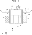
- Fig. 1 schematically shows the arrangement of an X-ray generation apparatus 1 according to the first embodiment.
- the X-ray generation apparatus 1 can be formed as a transmission type X-ray generation apparatus.
- the X-ray generation apparatus 1 includes an X-ray generation tube XG.
- the X-ray generation tube XG can include an electron gun EG and a target 22 that receives an electron beam or electrons emitted from the electron gun EG to generate X-rays.
- the X-ray generation tube XG can include an insulating tube 10 with two opening ends, an anode 20 that closes one of the two opening ends of the insulating tube 10, and a closing member 30 that closes the other of the two opening ends of the insulating tube 10.
- the anode 20 can include the target 22, a target holding plate 21 that holds the target 22, and an electrode 23 that applies a potential to the target 22 via the target holding plate 21 while supporting the target holding plate 21.
- the closing member 30 can be configured to hold the electron gun EG.
- the insulating tube 10, the anode 20, and the closing member 30 can form a container that defines an enclosed space.
- the enclosed space can be maintained at a vacuum or a high degree of vacuum.
- the X-ray generation apparatus 1 can further include a tube support structure 60 that supports the X-ray generation tube XG, and a deflector 50 that deflects the electron beam emitted from the electron gun EG.
- the X-ray generation apparatus 1 can include a deflector support structure 70 that supports the deflector 50.
- the tube support structure 60 can support the X-ray generation tube XG0 so as to permit at least the target 22 to be pivoted in a state in which the deflector 50 is fixed. From another viewpoint, the tube support structure 60 can support the X-ray generation tube XG so as to permit the X-ray generation tube XG to be pivoted in a state in which the deflector 50 is fixed.
- the tube support structure 60 can support the X-ray generation tube XG0 so as to permit the X-ray generation tube XG to be pivoted in a state in which the deflector 50 is supported by the deflector support structure 70.
- the tube support structure 60 and the deflector support structure 70 are structures that individually support the X-ray generation tube XG and the deflector 50.
- the X-ray generation tube XG may be pivoted manually by an operator or the like or may be pivoted by a driving mechanism (not shown).
- the deflector 50 may be formed from a permanent magnet, an electromagnet, or a permanent magnet and an electromagnet.
- the deflector 50 can include a first magnet and a second magnet.
- the first magnetic pole (for example, the S-pole) of the first magnet and the second magnetic pole (for example, the N-pole) of the second magnet can be arranged to face each other via the insulating tube 10 or the X-ray generating tube XG.
- the deflector 50 may be formed from one magnet arranged such that its magnetic pole faces in the radial direction of the insulating tube 10 or the X-ray generating tube XG.
- the deflector 50 may detachably be supported by the deflector support structure 70.
- the deflector support structure 70 may include a driving mechanism that moves and/or rotates the deflector 50 or an adjustment mechanism that adjusts the position or orientation of the deflector 50. By providing such driving mechanism or adjustment mechanism, it is possible to adjust the magnetic field exerted on the electron beam emitted from the X-ray generation tube XG.
- the electrode 23 is electrically connected to the target 22 and applies a potential to the target 22.
- the target 22 When electrons from the electron gun EG collide against the target 22, the target 22 generates X-rays.
- the X-rays generated by the target 22 are transmitted through the target holding plate 21 and emitted outside the X-ray generating tube XG.
- the anode 20 can be maintained at, for example, the ground potential but may be maintained at another potential.
- the target 22 may have a circular shape and may be formed from a single metal or a single alloy.
- the single metal may contain a small amount of unintended impurity.
- the single alloy is a metal material obtained by mixing one or more kinds of other elements with a pure metal.
- the target 22 may have an axisymmetric structure and may be formed from a single metal or single alloy.
- the target 22 is desirably formed from a material having a high melting point, for example, tungsten, tantalum, or molybdenum. These materials are advantageous in improving the generation efficiency of X-rays.
- the target holding plate 21 can be formed from, for example, a material that can easily transmit X-rays, such as beryllium or diamond.
- Fig. 3 schematically shows two states ST11 and ST12 of an X-ray generation apparatus according to a comparative example.
- Either of the two states ST11 and ST12 shows a state when viewing a target 22 from the side of an electron gun EG.
- the electron beam emitted from the electron gun EG is deflected by the magnetic field generated by a deflector 50, and enters a position P1 of the target 22.
- the state ST12 is a state in which the deflector 50 is pivoted with respect to the arrangement of the deflector 50 in the state ST11.
- a position P2 at which the electron beam enters the target 22 in the state ST12 is a position obtained by pivoting, about a center axis AX, the position P1 at which the electron beam enters the target 22 in the state ST11. That is, in the comparative example, the position at which the electron beam enters the target 22 is changed from the position P1 to the position P2 by pivoting the deflector 50. In the comparative example, this can prolong the life of the target 22 or an X-ray generation apparatus 1.
- Fig. 4 schematically shows two states ST21 and ST22 of the X-ray generation apparatus 1 according to the first embodiment.
- Either of the two states ST21 and ST22 shows a state when viewing the target 22 from the side of the electron gun EG.
- the electron beam emitted from the electron gun EG is deflected by the magnetic field generated by the deflector 50, and enters a position P1 of the target 22.
- the X-ray generation tube XG (target 22) is pivoted with respect to the azimuth of the X-ray generation tube XG (target 22) in the state ST21, and the electron beam enters a position P2 of the target 22.
- the pivot angle of the target 22 is 90° but the pivot angle can arbitrarily be set.
- a pivot angle of 3° or more is desirable.
- a pivot angle of 10° or more is more desirable.
- Reference numeral 25 denotes a virtual azimuth mark given to the target 22.
- the X-ray generation tube XG target 22
- the deflector 50 is fixed. Therefore, the electron beam enters the different positions P1 and P2 of the target 22 in the states ST21 and ST22, respectively.
- the positions P1 and P2 viewed from the X-ray detector that is, the positions P1 and P2 in the space where the X-ray generation apparatus 1 is arranged are the identical positions. This can prolong the life of the target 22 or the X-ray generation apparatus 1 without changing the positions P1 and P2 in the space where the X-ray generation apparatus 1 is arranged, that is, the focus position.
- an adjustment method of the X-ray generation apparatus 1 includes a pivot step of pivoting the X-ray generation tube XG in a state in which the deflector 50 is fixed.
- the pivot step can be executed in accordance with the use amount of the X-ray generation apparatus 1.
- the use amount can be, for example, at least one of the use time of the X-ray generation apparatus 1, a power amount applied to the electrode 23, and the cumulative value of the X-rays generated by the X-ray generation apparatus 1.
- the pivot step can be executed in accordance with the change of the X-rays generated by the X-ray generation apparatus 1.
- the pivot step can be executed when the intensity of the X-rays generated by the X-ray generation apparatus 1 becomes lower than a predetermined percentage of the intensity of the X-rays generated by the X-ray generation apparatus 1 immediately after the last pivot step is executed.
- the tube support structure 60 can support the X-ray generation tube XG so as to permit the X-ray generation tube XG to be pivoted about a pivot axis coinciding with the center axis AX of the electron gun EG.
- the center axis AX of the electron gun EG can be arranged to pass through the center of the target 22. In a case where the electron beam EB is not deflected by the deflector 50, the electron beam EB can enter the center of the target 22.
- Fig. 5 schematically shows the arrangement of an X-ray generation apparatus 1 according to the second embodiment. Matters not mentioned as the X-ray generation apparatus 1 of the second embodiment can comply with the first embodiment.
- a tube support structure 60 includes a storage portion 80 that surrounds an X-ray generation tube XG.
- the storage portion 80 can support the X-ray generation tube XG so as to permit the X-ray generation tube XG to be pivoted in a state in which a deflector 50 is fixed.
- An insulating fluid (for example, insulating oil) is filled or arranged in a space between the X-ray generation tube XG and the storage portion 80.
- the X-ray generation apparatus 1 may include an O-ring 82, and the X-ray generation tube XG and the storage portion 80 can have seal surfaces facing each other via the O-ring 82.
- the storage portion 80 may include a seal portion 81.
- the seal portion 81 can include a concave portion that covers a first surface 231 and a second surface 232 on the opposite sides in the outer peripheral portion of the electrode 23 of the anode 20, and an end face 233 of the peripheral portion.
- the O-ring 82 can be arranged to contact the end face 233 or arranged in the concave portion formed in the end face 233.
- a deflector support structure 70 that supports the deflector 50 can be connected to the storage portion 80.
- Fig. 6 schematically shows the arrangement of an X-ray generation apparatus 1 according to the third embodiment. Matters not mentioned as the X-ray generation apparatus 1 of the third embodiment can comply with the first or second embodiment.
- a through hole 24 can be formed in an electrode 23.
- An O-ring 82 can be arranged between the upper surface of a storage portion 80 and the lower surface of the electrode 23.
- the electrode 23 (an anode 20) can be fixed to the storage portion 80 by a screw 83 extending through the through hole 24.
- the through hole 24 can be formed as a long hole so as to permit the pivot of an X-ray generation tube XG with respect to a tube support structure 60.
- a torque can be managed not to lose the seal by the O-ring 82.
- the rotation angle of the screw 83 can be limited to a predetermined angle or smaller so the seal by the O-ring 82 is not lost when loosening the screw 83 to pivot the X-ray generation tube XG.
- Fig. 7 schematically shows the arrangement of an X-ray generation apparatus 1 according to the fourth embodiment. Matters not mentioned as the X-ray generation apparatus 1 of the fourth embodiment can comply with the third embodiment.
- a regulation member 84 that regulates the position of an electrode 23 may be provided.
- the regulation member 84 can have, for example, a ring shape.
- a through hole 85 can be formed in the regulation member 84.
- An O-ring 82 can be arranged between the upper surface of a storage portion 80 and the lower surface of the electrode 23.
- the regulation member 84 can be fixed to the storage portion 80 by pressing the electrode 23 against the O-ring 82 by a screw 83 extending through the through hole 85.
- the through hole 85 can be formed as a long hole so as to permit the pivot of an X-ray generation tube XG with respect to a tube support structure 60.
- Fig. 8 schematically shows the arrangement of an X-ray generation apparatus 1 according to the fifth embodiment. Matters not mentioned as the X-ray generation apparatus 1 of the fifth embodiment can comply with the first to fourth embodiments.
- the X-ray generation apparatus 1 can include a mark 93 representing the pivot angle of an X-ray generation tube XG with respect to a tube support structure 60.
- the X-ray generation apparatus 1 may include an engaging portion 91 that engages with a jig (not shown) to pivot the X-ray generation tube XG. An operator can engage the jig with engaging portion 91, and operate the jig, thereby pivoting the X-ray generation tube XG.
- Fig. 9 schematically shows the arrangement of an X-ray generation apparatus 1 according to the sixth embodiment. Matters not mentioned as the X-ray generation apparatus 1 of the sixth embodiment can comply with the first to fourth embodiments.
- the X-ray generation apparatus 1 can include a mark 93 representing the pivot angle of an X-ray generation tube XG with respect to a tube support structure 60.
- the X-ray generation apparatus 1 may include an engaging portion 95 that engages with a jig (not shown) to pivot the X-ray generation tube XG. An operator can engage the jig with the engaging portion 95, and operate the jig, thereby pivoting the X-ray generation tube XG.
- Fig. 10 shows the arrangement of an X-ray generation apparatus 1 according to an embodiment.
- the X-ray generation apparatus 1 can include a boosting circuit 110 and a driving circuit 120 in addition to the above-described X-ray generation tube XG.
- the boosting circuit 110 can generate a boosted voltage by boosting a voltage supplied from the outside, and supply the boosted voltage to the driving circuit 120.
- the driving circuit 120 can drive the X-ray generation tube XG based on the boosted voltage supplied from the boosting circuit 110.
- the X-ray generation tube XG, the boosting circuit 110, and the driving circuit 120 can be stored in a storage portion 80, and a space inside the storage portion 80 can be filled with an insulating fluid.
- Fig. 11 shows the arrangement of an X-ray imaging apparatus 200 according to an embodiment.
- the X-ray imaging apparatus 200 can include an X-ray generation apparatus 1, and an X-ray detection apparatus 240 that detects X-rays XR emitted from the X-ray generation apparatus 1 and transmitted through an object 230.
- the X-ray detection apparatus 240 may further include a control apparatus 210 and a display apparatus 220.
- the X-ray detection apparatus 240 can include an X-ray detector 242 and a signal processing unit 244.
- the control apparatus 210 can control the X-ray generation apparatus 1 and the X-ray detection apparatus 240.
- the focus position of the X-rays (the incident position of the electron beam) emitted from the X-ray generation apparatus 1 is changed, it is necessary to align the X-ray detector 242 or the X-ray detection apparatus 240 accordingly.
- the X-ray generation apparatus 1 since it is possible to prolong the life of the target or the X-ray generation tube without changing the focus position, it is unnecessary to perform such alignment.
- X-ray generation apparatus EG: electron gun, 10: electron gun, 20: anode, 21: target holding plate, 22: target, 23: electrode, 30: closing member, 50: deflector, 60: tube support structure, 70: deflector support structure, AX: center axis, EB: electron beam, 80: storage portion
Landscapes
- X-Ray Techniques (AREA)
- Health & Medical Sciences (AREA)
- Engineering & Computer Science (AREA)
- Nuclear Medicine, Radiotherapy & Molecular Imaging (AREA)
- Pulmonology (AREA)
- Radiology & Medical Imaging (AREA)
- Theoretical Computer Science (AREA)
- Physics & Mathematics (AREA)
- Life Sciences & Earth Sciences (AREA)
- Chemical & Material Sciences (AREA)
- Analytical Chemistry (AREA)
- Biochemistry (AREA)
- General Health & Medical Sciences (AREA)
- General Physics & Mathematics (AREA)
- Immunology (AREA)
- Pathology (AREA)
Abstract
Description
- The present invention relates to an X-ray generation apparatus, an X-ray imaging apparatus, and an adjustment method of the X-ray generation apparatus.
- In a transmission type microfocus X-ray tube, a target is irradiated with an electron beam to generate X-rays. However, in such X-ray tube, heat is generated by irradiating a target with an electron beam, and thus the target readily degrades.
-
PTL 1 describes a technique in which a magnet portion is arranged around an X-ray generation tube bulb, and the irradiation position of an electron beam on a target is changed by rotating the magnet portion, thereby prolonging the life of the X-ray generation tube bulb. However, if the irradiation position of the electron beam on the target is changed by moving the magnet portion, as described inPTL 1, the emission position of X-rays from an X-ray generation apparatus, that is, the focus position is changed. Therefore, every time the magnet portion is moved, that is, every time the focus position is changed, it is necessary to align an X-ray detector for detecting the X-rays emitted from the X-ray generation apparatus. - PTL 1:
Japanese Patent No. 4309176 - The present invention provides a technique advantageous in prolonging the life of a target or an X-ray generation tube without changing a focus position.
- A first aspect of the present invention is directed to an X-ray imaging apparatus, and the X-ray imaging apparatus comprises: an X-ray generation apparatus including an X-ray generation tube that includes an electron gun and a target configured to receive an electron beam emitted from the electron gun to generate X-rays, a support structure configured to support the X-ray generation tube, and a deflector configured to deflect the electron beam; an X-ray detector configured to detect the X-rays emitted from the X-ray generation apparatus; and a control apparatus configured to control the X-ray generation apparatus. The support structure supports the X-ray generation tube so as to permit at least the target to be pivoted in a state in which the deflector is fixed. The control apparatus determines, based on a use amount of the X-ray generation apparatus and/or a change of the X-rays generated by the X-ray generation apparatus, whether it is necessary to pivot the target.
- A second aspect of the present invention is directed to an adjustment method of an X-ray generation apparatus, and the X-ray generation apparatus includes an X-ray generation tube that includes an electron gun and a target configured to receive an electron beam emitted from the electron gun to generate X-rays, a support structure configured to support the X-ray generation tube, and a deflector configured to deflect the electron beam. The method comprises: a pivot step of pivoting at least the target, in a state in which the deflector is fixed, in accordance with a use amount of the X-ray generation apparatus and/or a change of the X-rays generated by the X-ray generation apparatus.
- A third aspect of the present invention provides an X-ray generation apparatus, and the X-ray generation apparatus comprises: an X-ray generation tube including an electron gun and a target configured to receive an electron beam emitted from the electron gun to generate X-rays; a support structure configured to support the X-ray generation tube; and a deflector configured to deflect the electron beam. The target has a circular shape, and is formed from a single metal or a single alloy, and the support structure supports the X-ray generation tube so as to permit at least the target to be pivoted about a pivot axis coinciding with a center axis of the electron gun in a state in which the deflector is fixed.
-
-
Fig. 1 is a view schematically showing the arrangement of an X-ray generation apparatus according to the first embodiment; -
Fig. 2 is a view schematically showing a state in which an electron beam emitted from an electron gun collides against a target in the X-ray generation apparatus according to the first embodiment; -
Fig. 3 is a view schematically showing an adjustment method or a use method of an X-ray generation apparatus according to a comparative example; -
Fig. 4 is a view schematically showing an adjustment method or a use method of the X-ray generation apparatus according to the first embodiment; -
Fig. 5 is a view schematically showing the arrangement of an X-ray generation apparatus according to the second embodiment; -
Fig. 6 is a view schematically showing the arrangement of an X-ray generation apparatus according to the third embodiment; -
Fig. 7 is a view schematically showing the arrangement of an X-ray generation apparatus according to the fourth embodiment; -
Fig. 8 is a view schematically showing the arrangement of an X-ray generation apparatus according to the fifth embodiment; -
Fig. 9 is a view schematically showing the arrangement of an X-ray generation apparatus according to the sixth embodiment; -
Fig. 10 is a block diagram schematically showing the arrangement of an X-ray generation apparatus according to an embodiment; and -
Fig. 11 is a block diagram schematically showing the arrangement of an X-ray imaging apparatus according to an embodiment. - Hereinafter, embodiments will be described in detail with reference to the attached drawings. Note, the following embodiments are not intended to limit the scope of the claimed invention. Multiple features are described in the embodiments, but limitation is not made to an invention that requires all such features, and multiple such features may be combined as appropriate. Furthermore, in the attached drawings, the same reference numerals are given to the same or similar configurations, and redundant description thereof is omitted.
-
Fig. 1 schematically shows the arrangement of anX-ray generation apparatus 1 according to the first embodiment. TheX-ray generation apparatus 1 can be formed as a transmission type X-ray generation apparatus. TheX-ray generation apparatus 1 includes an X-ray generation tube XG. The X-ray generation tube XG can include an electron gun EG and atarget 22 that receives an electron beam or electrons emitted from the electron gun EG to generate X-rays. In an example, the X-ray generation tube XG can include aninsulating tube 10 with two opening ends, ananode 20 that closes one of the two opening ends of theinsulating tube 10, and aclosing member 30 that closes the other of the two opening ends of theinsulating tube 10. Theanode 20 can include thetarget 22, atarget holding plate 21 that holds thetarget 22, and anelectrode 23 that applies a potential to thetarget 22 via thetarget holding plate 21 while supporting thetarget holding plate 21. Theclosing member 30 can be configured to hold the electron gun EG. Theinsulating tube 10, theanode 20, and theclosing member 30 can form a container that defines an enclosed space. The enclosed space can be maintained at a vacuum or a high degree of vacuum. - The
X-ray generation apparatus 1 can further include atube support structure 60 that supports the X-ray generation tube XG, and adeflector 50 that deflects the electron beam emitted from the electron gun EG. In addition, theX-ray generation apparatus 1 can include adeflector support structure 70 that supports thedeflector 50. Thetube support structure 60 can support the X-ray generation tube XG0 so as to permit at least thetarget 22 to be pivoted in a state in which thedeflector 50 is fixed. From another viewpoint, thetube support structure 60 can support the X-ray generation tube XG so as to permit the X-ray generation tube XG to be pivoted in a state in which thedeflector 50 is fixed. From still another viewpoint, thetube support structure 60 can support the X-ray generation tube XG0 so as to permit the X-ray generation tube XG to be pivoted in a state in which thedeflector 50 is supported by thedeflector support structure 70. Thetube support structure 60 and thedeflector support structure 70 are structures that individually support the X-ray generation tube XG and thedeflector 50. For example, the X-ray generation tube XG may be pivoted manually by an operator or the like or may be pivoted by a driving mechanism (not shown). - The
deflector 50 can be arranged outside the X-ray generation tube XG. Thedeflector 50 can be arranged so that, for example, a virtual plane VP3 crossing thedeflector 50 is located between a virtual plane VP1 including the electron beam incident surface of the target 22 (the surface facing the electron gun EG) and a virtual plane VP2 including the distal end face (the surface on the side of the target 22) of the electron gun EG. The virtual planes VP1, VP2, and VP3 can be defined as planes vertically intersecting a center axis AX of the electron gun EG. Thedeflector 50 deflects the electron beam emitted from the electron gun EG by exerting a magnetic field on the electron beam. When thedeflector 50 deflects the electron beam, the incident position of the electron beam on thetarget 22 can be adjusted or shifted. - The
deflector 50 may be formed from a permanent magnet, an electromagnet, or a permanent magnet and an electromagnet. In an example, thedeflector 50 can include a first magnet and a second magnet. The first magnetic pole (for example, the S-pole) of the first magnet and the second magnetic pole (for example, the N-pole) of the second magnet can be arranged to face each other via theinsulating tube 10 or the X-ray generating tube XG. Thedeflector 50 may be formed from one magnet arranged such that its magnetic pole faces in the radial direction of theinsulating tube 10 or the X-ray generating tube XG. Thedeflector 50 may detachably be supported by thedeflector support structure 70. Thedeflector support structure 70 may include a driving mechanism that moves and/or rotates thedeflector 50 or an adjustment mechanism that adjusts the position or orientation of thedeflector 50. By providing such driving mechanism or adjustment mechanism, it is possible to adjust the magnetic field exerted on the electron beam emitted from the X-ray generation tube XG. - The
electrode 23 is electrically connected to thetarget 22 and applies a potential to thetarget 22. When electrons from the electron gun EG collide against thetarget 22, thetarget 22 generates X-rays. The X-rays generated by thetarget 22 are transmitted through thetarget holding plate 21 and emitted outside the X-ray generating tube XG. Theanode 20 can be maintained at, for example, the ground potential but may be maintained at another potential. Thetarget 22 may have a circular shape and may be formed from a single metal or a single alloy. The single metal may contain a small amount of unintended impurity. The single alloy is a metal material obtained by mixing one or more kinds of other elements with a pure metal. From another viewpoint, thetarget 22 may have an axisymmetric structure and may be formed from a single metal or single alloy. Thetarget 22 is desirably formed from a material having a high melting point, for example, tungsten, tantalum, or molybdenum. These materials are advantageous in improving the generation efficiency of X-rays. Thetarget holding plate 21 can be formed from, for example, a material that can easily transmit X-rays, such as beryllium or diamond. -
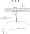
Fig. 2 schematically shows a state in which an electron beam EB emitted from the electron gun EG collides against thetarget 22. Referring toFig. 2 , the electron gun EG and thetarget 22 are close to each other. However, the electron gun EG and thetarget 22 can be arranged further separated from each other. The electron beam EB emitted from the electron gun EG enters or collides against thetarget 22 after being deflected by the magnetic field generated by thedeflector 50. The amount by which the electron beam EB is deflected, in other words, the incident position of the electron beam EB on thetarget 22 can depend on the magnetic field generated by thedeflector 50 and the accelerating voltage of the electron gun EG. -
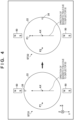
Fig. 3 schematically shows two states ST11 and ST12 of an X-ray generation apparatus according to a comparative example. Either of the two states ST11 and ST12 shows a state when viewing atarget 22 from the side of an electron gun EG. In the state ST11, the electron beam emitted from the electron gun EG is deflected by the magnetic field generated by adeflector 50, and enters a position P1 of thetarget 22. The state ST12 is a state in which thedeflector 50 is pivoted with respect to the arrangement of thedeflector 50 in the state ST11. Therefore, a position P2 at which the electron beam enters thetarget 22 in the state ST12 is a position obtained by pivoting, about a center axis AX, the position P1 at which the electron beam enters thetarget 22 in the state ST11. That is, in the comparative example, the position at which the electron beam enters thetarget 22 is changed from the position P1 to the position P2 by pivoting thedeflector 50. In the comparative example, this can prolong the life of thetarget 22 or anX-ray generation apparatus 1. However, when the position at which the electron beam enters thetarget 22 is changed from the position P1 to the position P2, this means that the position at which thetarget 22 emits X-rays, that is, the focus position of the X-rays in the X-ray inspection apparatus is changed. Therefore, in the comparative example, when the position at which the electron beam enters thetarget 22 is changed by the pivot of thedeflector 50, it is necessary to adjust the position of the X-ray detector. -
Fig. 4 schematically shows two states ST21 and ST22 of theX-ray generation apparatus 1 according to the first embodiment. Either of the two states ST21 and ST22 shows a state when viewing thetarget 22 from the side of the electron gun EG. In the state ST21, the electron beam emitted from the electron gun EG is deflected by the magnetic field generated by thedeflector 50, and enters a position P1 of thetarget 22. In the state ST22, the X-ray generation tube XG (target 22) is pivoted with respect to the azimuth of the X-ray generation tube XG (target 22) in the state ST21, and the electron beam enters a position P2 of thetarget 22. In this example, the pivot angle of thetarget 22 is 90° but the pivot angle can arbitrarily be set. For example, in consideration of the deflection of the electron beam, the damage range on thetarget 22 caused by the incidence of the electron beam, and the like, a pivot angle of 3° or more is desirable. In consideration of the pivot accuracy and a change in incident position of the electron beam, a pivot angle of 10° or more is more desirable.Reference numeral 25 denotes a virtual azimuth mark given to thetarget 22. In the first embodiment, the X-ray generation tube XG (target 22) is pivoted in a state in which thedeflector 50 is fixed. Therefore, the electron beam enters the different positions P1 and P2 of thetarget 22 in the states ST21 and ST22, respectively. However, the positions P1 and P2 viewed from the X-ray detector, that is, the positions P1 and P2 in the space where theX-ray generation apparatus 1 is arranged are the identical positions. This can prolong the life of thetarget 22 or theX-ray generation apparatus 1 without changing the positions P1 and P2 in the space where theX-ray generation apparatus 1 is arranged, that is, the focus position. - As is apparent from the above description, an adjustment method of the
X-ray generation apparatus 1 according to the embodiment includes a pivot step of pivoting the X-ray generation tube XG in a state in which thedeflector 50 is fixed. The pivot step can be executed in accordance with the use amount of theX-ray generation apparatus 1. The use amount can be, for example, at least one of the use time of theX-ray generation apparatus 1, a power amount applied to theelectrode 23, and the cumulative value of the X-rays generated by theX-ray generation apparatus 1. Alternatively, the pivot step can be executed in accordance with the change of the X-rays generated by theX-ray generation apparatus 1. For example, the pivot step can be executed when the intensity of the X-rays generated by theX-ray generation apparatus 1 becomes lower than a predetermined percentage of the intensity of the X-rays generated by theX-ray generation apparatus 1 immediately after the last pivot step is executed. - The
tube support structure 60 can support the X-ray generation tube XG so as to permit the X-ray generation tube XG to be pivoted about a pivot axis coinciding with the center axis AX of the electron gun EG. The center axis AX of the electron gun EG can be arranged to pass through the center of thetarget 22. In a case where the electron beam EB is not deflected by thedeflector 50, the electron beam EB can enter the center of thetarget 22. -
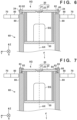
Fig. 5 schematically shows the arrangement of anX-ray generation apparatus 1 according to the second embodiment. Matters not mentioned as theX-ray generation apparatus 1 of the second embodiment can comply with the first embodiment. In the second embodiment, atube support structure 60 includes astorage portion 80 that surrounds an X-ray generation tube XG. Thestorage portion 80 can support the X-ray generation tube XG so as to permit the X-ray generation tube XG to be pivoted in a state in which adeflector 50 is fixed. An insulating fluid (for example, insulating oil) is filled or arranged in a space between the X-ray generation tube XG and thestorage portion 80. TheX-ray generation apparatus 1 may include an O-ring 82, and the X-ray generation tube XG and thestorage portion 80 can have seal surfaces facing each other via the O-ring 82. - The
storage portion 80 may include aseal portion 81. Theseal portion 81 can include a concave portion that covers afirst surface 231 and asecond surface 232 on the opposite sides in the outer peripheral portion of theelectrode 23 of theanode 20, and anend face 233 of the peripheral portion. The O-ring 82 can be arranged to contact theend face 233 or arranged in the concave portion formed in theend face 233. Adeflector support structure 70 that supports thedeflector 50 can be connected to thestorage portion 80. -
Fig. 6 schematically shows the arrangement of anX-ray generation apparatus 1 according to the third embodiment. Matters not mentioned as theX-ray generation apparatus 1 of the third embodiment can comply with the first or second embodiment. In the third embodiment, a throughhole 24 can be formed in anelectrode 23. An O-ring 82 can be arranged between the upper surface of astorage portion 80 and the lower surface of theelectrode 23. The electrode 23 (an anode 20) can be fixed to thestorage portion 80 by ascrew 83 extending through the throughhole 24. For example, the throughhole 24 can be formed as a long hole so as to permit the pivot of an X-ray generation tube XG with respect to atube support structure 60. When loosening thescrew 83 to pivot the X-ray generation tube XG, a torque can be managed not to lose the seal by the O-ring 82. Alternatively, the rotation angle of thescrew 83 can be limited to a predetermined angle or smaller so the seal by the O-ring 82 is not lost when loosening thescrew 83 to pivot the X-ray generation tube XG. -
Fig. 7 schematically shows the arrangement of anX-ray generation apparatus 1 according to the fourth embodiment. Matters not mentioned as theX-ray generation apparatus 1 of the fourth embodiment can comply with the third embodiment. In the fourth embodiment, aregulation member 84 that regulates the position of anelectrode 23 may be provided. Theregulation member 84 can have, for example, a ring shape. A throughhole 85 can be formed in theregulation member 84. An O-ring 82 can be arranged between the upper surface of astorage portion 80 and the lower surface of theelectrode 23. Theregulation member 84 can be fixed to thestorage portion 80 by pressing theelectrode 23 against the O-ring 82 by ascrew 83 extending through the throughhole 85. For example, the throughhole 85 can be formed as a long hole so as to permit the pivot of an X-ray generation tube XG with respect to atube support structure 60. -
Fig. 8 schematically shows the arrangement of anX-ray generation apparatus 1 according to the fifth embodiment. Matters not mentioned as theX-ray generation apparatus 1 of the fifth embodiment can comply with the first to fourth embodiments. TheX-ray generation apparatus 1 can include amark 93 representing the pivot angle of an X-ray generation tube XG with respect to atube support structure 60. TheX-ray generation apparatus 1 may include an engagingportion 91 that engages with a jig (not shown) to pivot the X-ray generation tube XG. An operator can engage the jig with engagingportion 91, and operate the jig, thereby pivoting the X-ray generation tube XG. -
Fig. 9 schematically shows the arrangement of anX-ray generation apparatus 1 according to the sixth embodiment. Matters not mentioned as theX-ray generation apparatus 1 of the sixth embodiment can comply with the first to fourth embodiments. TheX-ray generation apparatus 1 can include amark 93 representing the pivot angle of an X-ray generation tube XG with respect to atube support structure 60. TheX-ray generation apparatus 1 may include an engagingportion 95 that engages with a jig (not shown) to pivot the X-ray generation tube XG. An operator can engage the jig with the engagingportion 95, and operate the jig, thereby pivoting the X-ray generation tube XG. -
Fig. 10 shows the arrangement of anX-ray generation apparatus 1 according to an embodiment. TheX-ray generation apparatus 1 can include a boostingcircuit 110 and adriving circuit 120 in addition to the above-described X-ray generation tube XG. The boostingcircuit 110 can generate a boosted voltage by boosting a voltage supplied from the outside, and supply the boosted voltage to thedriving circuit 120. The drivingcircuit 120 can drive the X-ray generation tube XG based on the boosted voltage supplied from the boostingcircuit 110. The X-ray generation tube XG, the boostingcircuit 110, and the drivingcircuit 120 can be stored in astorage portion 80, and a space inside thestorage portion 80 can be filled with an insulating fluid. -
Fig. 11 shows the arrangement of anX-ray imaging apparatus 200 according to an embodiment. TheX-ray imaging apparatus 200 can include anX-ray generation apparatus 1, and anX-ray detection apparatus 240 that detects X-rays XR emitted from theX-ray generation apparatus 1 and transmitted through anobject 230. TheX-ray detection apparatus 240 may further include acontrol apparatus 210 and adisplay apparatus 220. TheX-ray detection apparatus 240 can include anX-ray detector 242 and asignal processing unit 244. Thecontrol apparatus 210 can control theX-ray generation apparatus 1 and theX-ray detection apparatus 240. TheX-ray detector 242 can detect or image the X-rays XR emitted from theX-ray generation apparatus 1 and transmitted through theobject 230. Thesignal processing unit 244 can process a signal output from theX-ray detector 242, and supply the processed signal to thecontrol apparatus 210. Thecontrol apparatus 210 displays an image on thedisplay apparatus 220 based on the signal supplied from thesignal processing unit 244. Based on the use amount of theX-ray generation apparatus 1 and/or the change of the X-rays generated by theX-ray generation apparatus 1, thecontrol apparatus 210 determines whether it is necessary to execute the pivot step. If it is determined that it is necessary to execute the pivot step, thecontrol apparatus 210 may use thedisplay apparatus 220 to prompt an operator to execute the pivot step. - As described above, if the focus position of the X-rays (the incident position of the electron beam) emitted from the
X-ray generation apparatus 1 is changed, it is necessary to align theX-ray detector 242 or theX-ray detection apparatus 240 accordingly. In theX-ray generation apparatus 1 according to each of the above-described embodiments, since it is possible to prolong the life of the target or the X-ray generation tube without changing the focus position, it is unnecessary to perform such alignment. - 1: X-ray generation apparatus, EG: electron gun, 10: electron gun, 20: anode, 21: target holding plate, 22: target, 23: electrode, 30: closing member, 50: deflector, 60: tube support structure, 70: deflector support structure, AX: center axis, EB: electron beam, 80: storage portion
Claims (18)
- An X-ray imaging apparatus comprising:an X-ray generation apparatus including an X-ray generation tube that includes an electron gun and a target configured to receive an electron beam emitted from the electron gun to generate X-rays, a support structure configured to support the X-ray generation tube, and a deflector configured to deflect the electron beam;an X-ray detector configured to detect the X-rays emitted from the X-ray generation apparatus; anda control apparatus configured to control the X-ray generation apparatus,wherein the support structure supports the X-ray generation tube so as to permit at least the target to be pivoted in a state in which the deflector is fixed, andthe control apparatus determines, based on a use amount of the X-ray generation apparatus and/or a change of the X-rays generated by the X-ray generation apparatus, whether it is necessary to pivot the target.
- The X-ray imaging apparatus according to claim 1, wherein the support structure supports the X-ray generation tube so as to permit the X-ray generation tube to be pivoted in the state in which the deflector is fixed.
- The X-ray imaging apparatus according to claim 1 or 2, wherein the support structure supports the X-ray generation tube so as to permit the X-ray generation tube to be pivoted about a pivot axis coinciding with a center axis of the electron gun.
- The X-ray imaging apparatus according to claim 3, wherein the center axis of the electron gun passes through a center of the target.
- The X-ray imaging apparatus according to any one of claims 1 to 4, wherein in a case where the electron beam is not deflected by the deflector, the electron beam enters the center of the target.
- The X-ray imaging apparatus according to any one of claims 1 to 5, whereinthe support structure includes a storage portion configured to surround the X-ray generation tube, andthe storage portion supports the X-ray generation tube so as to permit the X-ray generation tube to be pivoted in the state in which the deflector is fixed.
- The X-ray imaging apparatus according to claim 6, wherein an insulating fluid is arranged in a space between the X-ray generation tube and the storage portion.
- The X-ray imaging apparatus according to claim 7, further comprising an O-ring,
wherein the X-ray generation tube and the storage portion have seal surfaces facing each other via the O-ring. - The X-ray imaging apparatus according to any one of claims 6 to 8, wherein the deflector includes a first magnet and a second magnet that are arranged to face each other via the storage portion.
- The X-ray imaging apparatus according to any one of claims 1 to 9, wherein the X-ray generation tube includes a mark representing a pivot angle of the X-ray generation tube with respect to the support structure.
- An adjustment method of an X-ray generation apparatus including an X-ray generation tube that includes an electron gun and a target configured to receive an electron beam emitted from the electron gun to generate X-rays, a support structure configured to support the X-ray generation tube, and a deflector configured to deflect the electron beam, the method comprising:
a pivot step of pivoting at least the target, in a state in which the deflector is fixed, in accordance with a use amount of the X-ray generation apparatus and/or a change of the X-rays generated by the X-ray generation apparatus. - The adjustment method of the X-ray generation apparatus according to claim 11, wherein in the pivot step, the X-ray generation tube is pivoted in the state in which the deflector is fixed.
- The adjustment method of the X-ray generation apparatus according to claim 11 or 12, wherein in the pivot step, the X-ray generation tube is pivoted about a pivot axis coinciding with a center axis of the electron gun.
- The adjustment method of the X-ray generation apparatus according to claim 13, wherein the center axis of the electron gun passes through a center of the target.
- The adjustment method of the X-ray generation apparatus according to any one of claims 11 to 14, wherein in a case where the electron beam is not deflected by the deflector, the electron beam enters the center of the target.
- The adjustment method of the X-ray generation apparatus according to any one of claims 11 to 15, whereinthe support structure includes a storage portion configured to surround the X-ray generation tube, andin the pivot step, the X-ray generation tube is pivoted in a state in which the deflector and the storage portion are fixed.
- The adjustment method of the X-ray generation apparatus according to claim 16, wherein the deflector includes a first magnet and a second magnet that are arranged to face each other via the storage portion.
- An X-ray generation apparatus comprising:an X-ray generation tube including an electron gun and a target configured to receive an electron beam emitted from the electron gun to generate X-rays;a support structure configured to support the X-ray generation tube; anda deflector configured to deflect the electron beam,wherein the target has a circular shape, and is formed from a single metal or a single alloy, andthe support structure supports the X-ray generation tube so as to permit at least the target to be pivoted about a pivot axis coinciding with a center axis of the electron gun in a state in which the deflector is fixed.
Applications Claiming Priority (2)
| Application Number | Priority Date | Filing Date | Title |
|---|---|---|---|
| PCT/JP2022/016710 WO2023188337A1 (en) | 2022-03-31 | 2022-03-31 | X-ray generation device, x-ray imaging device, and method for adjusting x-ray generation device |
| PCT/JP2023/010620 WO2023189735A1 (en) | 2022-03-31 | 2023-03-17 | X-ray generator, x-ray imager, and method for adjusting x-ray generator |
Publications (2)
| Publication Number | Publication Date |
|---|---|
| EP4503086A1 true EP4503086A1 (en) | 2025-02-05 |
| EP4503086A4 EP4503086A4 (en) | 2025-08-20 |
Family
ID=87797940
Family Applications (1)
| Application Number | Title | Priority Date | Filing Date |
|---|---|---|---|
| EP23779751.9A Pending EP4503086A4 (en) | 2022-03-31 | 2023-03-17 | X-ray generator, X-ray imaging device and method for adjusting the X-ray generator |
Country Status (6)
| Country | Link |
|---|---|
| US (1) | US12106927B2 (en) |
| EP (1) | EP4503086A4 (en) |
| JP (1) | JP7337312B1 (en) |
| KR (1) | KR20240167050A (en) |
| CN (1) | CN118974869A (en) |
| TW (2) | TWI847631B (en) |
Families Citing this family (1)
| Publication number | Priority date | Publication date | Assignee | Title |
|---|---|---|---|---|
| US12213238B2 (en) * | 2022-10-18 | 2025-01-28 | Carl Zeiss X-ray Microscopy, Inc. | Reflection target X-ray source with steered beam on target |
Family Cites Families (17)
| Publication number | Priority date | Publication date | Assignee | Title |
|---|---|---|---|---|
| US4048496A (en) * | 1972-05-08 | 1977-09-13 | Albert Richard D | Selectable wavelength X-ray source, spectrometer and assay method |
| JP3030069B2 (en) | 1990-09-13 | 2000-04-10 | イメイトロン インコーポレーテッド | X-ray tube |
| DE19509516C1 (en) | 1995-03-20 | 1996-09-26 | Medixtec Gmbh Medizinische Ger | Microfocus X-ray device |
| DE19612698C1 (en) | 1996-03-29 | 1997-08-14 | Siemens Ag | X=ray generator with cooled rotary anode |
| JP3999399B2 (en) | 1999-03-29 | 2007-10-31 | 株式会社島津製作所 | X-ray tube |
| JP4309176B2 (en) | 2003-06-03 | 2009-08-05 | 株式会社東芝 | X-ray equipment |
| US8213576B2 (en) * | 2007-08-09 | 2012-07-03 | Shimadzu Corporation | X-ray tube apparatus |
| JP5221215B2 (en) | 2008-06-13 | 2013-06-26 | 浜松ホトニクス株式会社 | X-ray generator |
| JP6131623B2 (en) | 2013-02-13 | 2017-05-24 | 株式会社島津製作所 | Radiation generator |
| WO2014125702A1 (en) | 2013-02-18 | 2014-08-21 | 株式会社島津製作所 | Rotating envelope x-ray tube device |
| JP2016162525A (en) * | 2015-02-27 | 2016-09-05 | 東芝電子管デバイス株式会社 | X-ray tube device |
| JP6611490B2 (en) | 2015-07-02 | 2019-11-27 | キヤノン株式会社 | X-ray generator and X-ray imaging system using the same |
| JP6667366B2 (en) | 2016-05-23 | 2020-03-18 | キヤノン株式会社 | X-ray generator tube, X-ray generator, and X-ray imaging system |
| JP6849518B2 (en) | 2017-04-28 | 2021-03-24 | 浜松ホトニクス株式会社 | X-ray tube and X-ray generator |
| EP3493239A1 (en) * | 2017-12-01 | 2019-06-05 | Excillum AB | X-ray source and method for generating x-ray radiation |
| JP7090900B2 (en) * | 2018-09-26 | 2022-06-27 | 株式会社リガク | X-ray generator and X-ray analyzer |
| CN112665879B (en) * | 2020-12-31 | 2024-11-12 | 华中科技大学 | A target surface deviation measurement and adjustment method and device for a wheel posture measurement system |
-
2023
- 2023-03-17 JP JP2023546351A patent/JP7337312B1/en active Active
- 2023-03-17 CN CN202380032188.5A patent/CN118974869A/en active Pending
- 2023-03-17 KR KR1020247035450A patent/KR20240167050A/en active Pending
- 2023-03-17 EP EP23779751.9A patent/EP4503086A4/en active Pending
- 2023-03-27 TW TW112111516A patent/TWI847631B/en active
- 2023-03-27 TW TW113120432A patent/TW202437298A/en unknown
- 2023-11-15 US US18/509,608 patent/US12106927B2/en active Active
Also Published As
| Publication number | Publication date |
|---|---|
| EP4503086A4 (en) | 2025-08-20 |
| JPWO2023189735A1 (en) | 2023-10-05 |
| US20240087833A1 (en) | 2024-03-14 |
| TW202437298A (en) | 2024-09-16 |
| TW202401475A (en) | 2024-01-01 |
| TWI847631B (en) | 2024-07-01 |
| US12106927B2 (en) | 2024-10-01 |
| CN118974869A (en) | 2024-11-15 |
| JP7337312B1 (en) | 2023-09-01 |
| KR20240167050A (en) | 2024-11-26 |
Similar Documents
| Publication | Publication Date | Title |
|---|---|---|
| US6438207B1 (en) | X-ray tube having improved focal spot control | |
| CN1698175A (en) | X-ray device | |
| EP2869327A1 (en) | X-ray tube | |
| JP5426089B2 (en) | X-ray tube and X-ray CT apparatus | |
| US11636995B2 (en) | X-ray generation device and X-ray analysis apparatus | |
| JPWO2011001797A1 (en) | Gas field ionization ion source apparatus and scanning charged particle microscope equipped with the same | |
| US12106927B2 (en) | X-ray generation apparatus, x-ray imaging apparatus, and adjustment method of x-ray generation apparatus | |
| SE424243B (en) | RONTGENROR FOR RONTGENDIAGNOSTIC EQUIPMENT | |
| US20240321542A1 (en) | X-ray generation device | |
| EP4358112A2 (en) | Reflection target x-ray source with steered beam on target | |
| US12035451B2 (en) | Method and system for liquid cooling isolated x-ray transmission target | |
| JP2012196327A (en) | Axis alignment method and x-ray imaging system | |
| JP2007522622A (en) | Cathode head with focus control | |
| WO2023189735A1 (en) | X-ray generator, x-ray imager, and method for adjusting x-ray generator | |
| US12597581B2 (en) | X-ray generation device | |
| JP7394271B1 (en) | X-ray generator, X-ray imaging device, and method for adjusting the X-ray generator | |
| JP2002008572A (en) | X-ray tube | |
| JP2007305337A (en) | Microfocus x-ray tube | |
| KR101897460B1 (en) | Replaceable electron gun for electron microscope and electron microscope comprising the same | |
| US11823860B1 (en) | X-ray generating apparatus, method of adjusting target, and method of using X-ray generating apparatus | |
| US12412726B2 (en) | X-ray generation device and X-ray imaging system | |
| KR20180042328A (en) | X-ray generator and method, and sample measurement system | |
| JP2016039056A (en) | X-ray tube device |
Legal Events
| Date | Code | Title | Description |
|---|---|---|---|
| STAA | Information on the status of an ep patent application or granted ep patent |
Free format text: STATUS: THE INTERNATIONAL PUBLICATION HAS BEEN MADE |
|
| PUAI | Public reference made under article 153(3) epc to a published international application that has entered the european phase |
Free format text: ORIGINAL CODE: 0009012 |
|
| STAA | Information on the status of an ep patent application or granted ep patent |
Free format text: STATUS: REQUEST FOR EXAMINATION WAS MADE |
|
| 17P | Request for examination filed |
Effective date: 20241015 |
|
| AK | Designated contracting states |
Kind code of ref document: A1 Designated state(s): AL AT BE BG CH CY CZ DE DK EE ES FI FR GB GR HR HU IE IS IT LI LT LU LV MC ME MK MT NL NO PL PT RO RS SE SI SK SM TR |
|
| DAV | Request for validation of the european patent (deleted) | ||
| DAX | Request for extension of the european patent (deleted) | ||
| A4 | Supplementary search report drawn up and despatched |
Effective date: 20250717 |
|
| RIC1 | Information provided on ipc code assigned before grant |
Ipc: H01J 35/08 20060101AFI20250711BHEP Ipc: H01J 35/10 20060101ALI20250711BHEP Ipc: H05G 1/52 20060101ALI20250711BHEP |