EP4502621A1 - Measurement system and measurement method - Google Patents
Measurement system and measurement method Download PDFInfo
- Publication number
- EP4502621A1 EP4502621A1 EP23779903.6A EP23779903A EP4502621A1 EP 4502621 A1 EP4502621 A1 EP 4502621A1 EP 23779903 A EP23779903 A EP 23779903A EP 4502621 A1 EP4502621 A1 EP 4502621A1
- Authority
- EP
- European Patent Office
- Prior art keywords
- sheet
- frame
- speed
- frames
- calculated
- Prior art date
- Legal status (The legal status is an assumption and is not a legal conclusion. Google has not performed a legal analysis and makes no representation as to the accuracy of the status listed.)
- Pending
Links
Images


Classifications
-
- G—PHYSICS
- G01—MEASURING; TESTING
- G01P—MEASURING LINEAR OR ANGULAR SPEED, ACCELERATION, DECELERATION, OR SHOCK; INDICATING PRESENCE, ABSENCE, OR DIRECTION, OF MOVEMENT
- G01P3/00—Measuring linear or angular speed; Measuring differences of linear or angular speeds
- G01P3/42—Devices characterised by the use of electric or magnetic means
- G01P3/44—Devices characterised by the use of electric or magnetic means for measuring angular speed
- G01P3/48—Devices characterised by the use of electric or magnetic means for measuring angular speed by measuring frequency of generated current or voltage
- G01P3/481—Devices characterised by the use of electric or magnetic means for measuring angular speed by measuring frequency of generated current or voltage of pulse signals
-
- G—PHYSICS
- G01—MEASURING; TESTING
- G01P—MEASURING LINEAR OR ANGULAR SPEED, ACCELERATION, DECELERATION, OR SHOCK; INDICATING PRESENCE, ABSENCE, OR DIRECTION, OF MOVEMENT
- G01P3/00—Measuring linear or angular speed; Measuring differences of linear or angular speeds
- G01P3/36—Devices characterised by the use of optical means, e.g. using infrared, visible, or ultraviolet light
-
- G—PHYSICS
- G01—MEASURING; TESTING
- G01B—MEASURING LENGTH, THICKNESS OR SIMILAR LINEAR DIMENSIONS; MEASURING ANGLES; MEASURING AREAS; MEASURING IRREGULARITIES OF SURFACES OR CONTOURS
- G01B15/00—Measuring arrangements characterised by the use of electromagnetic waves or particle radiation, e.g. by the use of microwaves, X-rays, gamma rays or electrons
- G01B15/02—Measuring arrangements characterised by the use of electromagnetic waves or particle radiation, e.g. by the use of microwaves, X-rays, gamma rays or electrons for measuring thickness
-
- G—PHYSICS
- G01—MEASURING; TESTING
- G01B—MEASURING LENGTH, THICKNESS OR SIMILAR LINEAR DIMENSIONS; MEASURING ANGLES; MEASURING AREAS; MEASURING IRREGULARITIES OF SURFACES OR CONTOURS
- G01B15/00—Measuring arrangements characterised by the use of electromagnetic waves or particle radiation, e.g. by the use of microwaves, X-rays, gamma rays or electrons
- G01B15/02—Measuring arrangements characterised by the use of electromagnetic waves or particle radiation, e.g. by the use of microwaves, X-rays, gamma rays or electrons for measuring thickness
- G01B15/025—Measuring arrangements characterised by the use of electromagnetic waves or particle radiation, e.g. by the use of microwaves, X-rays, gamma rays or electrons for measuring thickness by measuring absorption
-
- G—PHYSICS
- G01—MEASURING; TESTING
- G01D—MEASURING NOT SPECIALLY ADAPTED FOR A SPECIFIC VARIABLE; ARRANGEMENTS FOR MEASURING TWO OR MORE VARIABLES NOT COVERED IN A SINGLE OTHER SUBCLASS; TARIFF METERING APPARATUS; MEASURING OR TESTING NOT OTHERWISE PROVIDED FOR
- G01D5/00—Mechanical means for transferring the output of a sensing member; Means for converting the output of a sensing member to another variable where the form or nature of the sensing member does not constrain the means for converting; Transducers not specially adapted for a specific variable
- G01D5/12—Mechanical means for transferring the output of a sensing member; Means for converting the output of a sensing member to another variable where the form or nature of the sensing member does not constrain the means for converting; Transducers not specially adapted for a specific variable using electric or magnetic means
- G01D5/244—Mechanical means for transferring the output of a sensing member; Means for converting the output of a sensing member to another variable where the form or nature of the sensing member does not constrain the means for converting; Transducers not specially adapted for a specific variable using electric or magnetic means influencing characteristics of pulses or pulse trains; generating pulses or pulse trains
- G01D5/245—Mechanical means for transferring the output of a sensing member; Means for converting the output of a sensing member to another variable where the form or nature of the sensing member does not constrain the means for converting; Transducers not specially adapted for a specific variable using electric or magnetic means influencing characteristics of pulses or pulse trains; generating pulses or pulse trains using a variable number of pulses in a train
-
- G—PHYSICS
- G01—MEASURING; TESTING
- G01G—WEIGHING
- G01G11/00—Apparatus for weighing a continuous stream of material during flow; Conveyor belt weighers
-
- G—PHYSICS
- G01—MEASURING; TESTING
- G01P—MEASURING LINEAR OR ANGULAR SPEED, ACCELERATION, DECELERATION, OR SHOCK; INDICATING PRESENCE, ABSENCE, OR DIRECTION, OF MOVEMENT
- G01P21/00—Testing or calibrating of apparatus or devices covered by the preceding groups
- G01P21/02—Testing or calibrating of apparatus or devices covered by the preceding groups of speedometers
-
- G—PHYSICS
- G01—MEASURING; TESTING
- G01P—MEASURING LINEAR OR ANGULAR SPEED, ACCELERATION, DECELERATION, OR SHOCK; INDICATING PRESENCE, ABSENCE, OR DIRECTION, OF MOVEMENT
- G01P3/00—Measuring linear or angular speed; Measuring differences of linear or angular speeds
- G01P3/42—Devices characterised by the use of electric or magnetic means
- G01P3/50—Devices characterised by the use of electric or magnetic means for measuring linear speed
Definitions
- the present invention relates to a measurement system and a measurement method.
- Patent Literature 1 It is known to synchronously control a plurality of frames for scanning and measuring a sheet being conveyed.
- Patent Literature 1 JP 7-204565 A
- One aspect of the present invention makes it possible to reduce lowering of accuracy of synchronization control for a plurality of frames.
- a measurement system includes a plurality of frames each of which scans and measures a sheet being conveyed, and a synchronization control unit which synchronously controls each of the frames, wherein the synchronization control unit includes a speed calculator which calculates a speed of the sheet in each of the frames, and a controller which controls each of the frames so that each of the frames scans and measures an equal position of the sheet on a basis of a calculated speed of the sheet in each of the frames calculated by the speed calculator.
- a measurement method using a plurality of frames each of which scans and measures a sheet being conveyed includes calculating a speed of the sheet in each of the frames, and controlling each of the frames so that each of the frames scans and measures an equal position of the sheet on a basis of a calculated speed of the sheet in each of the frames calculated.
- FIG. 1 is a diagram illustrating an example of a schematic configuration of a measurement system according to a first embodiment.
- a measurement system 100 measures a sheet 9 being conveyed. Examples of the sheet 9 include paper, resin, and a battery electrode sheet. For example, the sheet 9 during the manufacturing process is measured by the measurement system 100. Examples of a process included in the production process are a coating process and a drying process.
- the measurement system 100 includes a plurality of frames 1, a plurality of rollers 2, an operator station 3 and a synchronization control unit 4.
- Each of the plurality of frames 1 is disposed such that the sheet 9 passes through the inside of the frame, and scans and measures the sheet 9 being conveyed.
- a sensor head is used for the measurement.
- the frame 1 includes a sensor head 11 and a sensor head 12. Description will be given with reference to FIG. 2 as well.
- FIG. 2 is a diagram illustrating an example of a schematic configuration of the frame.
- the frame 1 has a ring shape through which the sheet 9 can pass.
- Such a frame 1 is also referred to as an O-shaped frame or the like.
- the sensor head 11 and the sensor head 12 are attached to the frame 1 and supported.
- the sensor head 11 and the sensor head 12 scan the sheet 9 by moving in the frame 1 in a direction intersecting with (for example, a direction orthogonal to) the conveying direction of the sheet 9.
- the scanned position on the sheet 9 is referred to as a scanned position 9P, and is schematically illustrated.
- the sensor head 11 and the sensor head 12 are arranged so as to be located on opposite sides with the sheet 9 interposed therebetween, and move together so as to scan the entire width of the sheet 9 while repeating forward movement and backward movement in a state where the positional relationship is fixed.
- the sensor head 11 and the sensor head 12 are driven by, for example, a not-illustrated actuator.
- a radiation source such as ⁇ rays and X-rays is provided in the sensor head 11.
- a radiation detector that detects radiation from the sensor head 11 is mounted on the sensor head 12. Radiation from the sensor head 11 is transmitted through the sheet 9 and is detected by the sensor head 12. By doing so, the transmission amount and the attenuation amount (which may be the transmittance and the attenuation rate) of the radiation transmitted through the sheet 9 are detected.
- the thickness of the sheet 9 is calculated on the basis of a calibration curve indicating a relationship between the transmittance or the like of the sheet 9 and the thickness of the sheet 9. The thickness of the sheet 9 can be measured.
- a frame 1-1 to a frame 1-5 are exemplified.
- the sheet 9 is conveyed so as to pass through the frame 1-1 to the frame 1-5 in this order.
- the thickness of the sheet 9 in a state before coating is measured by the frame 1-1.
- a coater C-1 applies a coating material to the front surface of the sheet 9.
- the frame 1-2 measures the thickness of the sheet 9 in a state where the coating material is applied to the front surface. Thereafter, the sheet 9 passes through a drying furnace D-1.
- the frame 1-3 measures the thickness of the sheet 9 in a dried state.
- a coater C-2 applies a coating material to the rear surface of the sheet 9.
- the frame 1-4 measures the thickness of the sheet 9 in a state where the coating material is applied to the rear surface. Thereafter, the sheet 9 passes through a drying furnace D-2.
- the frame 1-5 measures the thickness of the sheet 9 in a dried state.
- the distance between the frames 1 in the conveying direction of the sheet 9 is referred to as a path length L.
- the path length L include a path length L 12 between the frame 1-1 and the frame 1-2, a path length L 23 between the frame 1-2 and the frame 1-3, a path length L 34 between the frame 1-3 and the frame 1-4, and a path length L 45 between the frame 1-4 and the frame 1-5.
- the roller 2 is one of the components of a conveying device for the sheet 9.
- An example of the conveying device includes a conveyor.
- the roller 2 rotates in accordance with the movement of the sheet 9 conveyed.
- the rollers 2, out of the plurality of rollers 2, located near the frame 1-1 to the frame 1-5 are referred to as a roller 2-1 to a roller 2-5, respectively, and are illustrated in the figure.
- the rotation of at least some of the plurality of rollers 2 is detected by an encoder.
- the signal indicating the detection result is referred to as an encoder signal ES.
- the encoder signal ES is transmitted from the encoder of the roller 2 to the synchronization control unit 4.
- the rotation of at least the roller 2-1 to the roller 2-5 is detected by the encoder.
- the encoder signals ES of the roller 2-1 to the roller 2-5 are referred to as an encoder signal ES-1 to an encoder signal ES-5, respectively, and are illustrated in the figure.
- the operator station 3 acquires a measurement result in each frame 1, specifically, data of the thickness of the sheet 9.
- the measurement result is displayed to the operator by, for example, a monitor.
- a necessary operation is performed according to the measurement result. For example, parameters of the coater C-1, the coater C-2, the drying furnace D-1, the drying furnace D-2, and the like are adjusted so that the thickness of the sheet 9 becomes a target thickness.
- the synchronization control unit 4 synchronously controls the respective frames 1.
- the functional blocks of the synchronization control unit 4 are also illustrated in FIG. 1 .
- the synchronization control unit 4 includes a speed calculator 41 and a controller 42.
- the speed calculator 41 calculates the speed of the sheet 9 in each frame 1.
- the speed calculator 41 calculates the speed of the sheet 9 in each frame 1 on the basis of the encoder signal ES from the roller 2 near the frame 1. For example, on the basis of the rotating speed of the roller 2 grasped from the encoder signal ES, the speed of the sheet 9 in the corresponding frame 1 is calculated.
- the speeds of the sheet 9 in the frame 1-1 to the frame 1-5 are calculated.
- the speed of the sheet 9 calculated by the speed calculator 41 is also referred to as a calculated speed V.
- the calculated speeds V in the respective frames 1 may be different from each other.
- One of the factors is the extension of the sheet 9 being conveyed.
- the sheet 9 extends at the time of conveyance.
- the frames 1 are appropriately synchronously controlled.
- the controller 42 controls each frame 1 so that the frame 1 scans and measures the same position of the sheet 9 on the basis of the calculated speed V of the sheet 9 in the frame 1.
- the scanning timing of each frame 1 that is, the driving timings of the sensor head 11 and the sensor head 12 are controlled so that the scanned position 9P of the sheet 9 in each frame 1 becomes the same.
- the controller 42 calculates delay time T of scanning of the latter frame 1 with respect to scanning of the former frame 1.
- the controller 42 calculates the delay time T by dividing the path length L between the former frame 1 and the latter frame 1 by the average speed of the calculated speed V of the sheet 9 in the former frame 1 and the calculated speed V of the sheet 9 in the latter frame 1.
- the calculated speed V of the sheet 9 in the frame 1-1 is defined as a calculated speed V 1 .
- the calculated speed V of the sheet 9 in the frame 1-2 is defined as a calculated speed V 2 .
- the path length L between the frame 1-1 and the frame 1-2 is defined as the path length L 12 as described above.
- the delay time T of scanning of the frame 1-2 with respect to scanning of the frame 1-1 is defined as delay time T 12 .
- the controller 42 calculates the delay time T 12 on the basis of Equation (1) described below, for example.
- T 12 L 12 / V 1 + V 2 /2
- delay time T 23 of scanning of the frame 1-3 with respect to scanning of the frame 1-2 is calculated.
- Delay time T 34 of scanning of the frame 1-4 with respect to scanning of the frame 1-3 is calculated.
- Delay time T 45 of scanning of the frame 1-5 with respect to scanning of the frame 1-4 is calculated.
- the controller 42 controls the scanning timing of the latter frame 1 on the basis of the calculated delay time T.
- the controller 42 controls the scanning timing of the latter frame 1 so that the scanning of the latter frame 1 is delayed by the delay time T further than the scanning of the former frame 1.
- the scanning timing of the frame 1-2 is controlled so that the scanning timing of the frame 1-2 is delayed by the delay time T 12 further than the scanning timing of the frame 1-1.
- the scanning timing of the frame 1-3 is controlled so that the scanning timing of the frame 1-3 is delayed by the delay time T 23 further than the scanning timing of the frame 1-2.
- the scanning timing of the frame 1-4 is controlled so that the scanning timing of the frame 1-4 is delayed by the delay time T 34 further than the scanning timing of the frame 1-3.
- the scanning timing of the frame 1-5 is controlled so that the scanning timing of the frame 1-5 is delayed by the delay time T 45 further than the scanning timing of the frame 1-4.
- the controller 42 controls each frame 1 by transmitting a command signal CS to the frame 1.
- the command signals CS transmitted to the frame 1-1 to the frame 1-5 are referred to as a command signal CS-1 to a command signal CS-5, respectively, and are illustrated in the figure.
- Each frame 1 drives the sensor head 11 and the sensor head 12 on the basis of the command signal CS from the controller 42 of the synchronization control unit 4.
- the respective frames 1 each drive the sensor head 11 and the sensor head 12 so that the frames 1 scan and measure the same position of the sheet 9.
- the frames 1 are controlled so that the frames 1 scan and measure the same position of the sheet 9 on the basis of the calculated speeds V of the sheet 9 in the frames 1.
- the thickness of the same scanned position 9P of the sheet 9 can be measured accurately.
- FIG. 3 is a flowchart illustrating an example of processing (measurement method) executed in the measurement system. Since the specific processing has been described above, the detailed description will be omitted.
- Step S1 the speed of the sheet in each frame is calculated.
- the speed calculator 41 of the synchronization control unit 4 calculates the speed of the sheet 9 in each frame 1 on the basis of the encoder signal ES from the roller 2 near the frame 1.
- Step S2 the respective frames are synchronously controlled.
- the controller 42 of the synchronization control unit 4 controls each frame 1 so that the frame 1 scans and measures the same position of the sheet 9 on the basis of the calculated speed V of the sheet 9 in the frame 1.
- the calculated speed V of the sheet 9 in some frames 1 may be different from the actual speed of the sheet 9. In such a case, a measure according to the second embodiment may be taken.
- FIG. 4 is a diagram illustrating an example of functional blocks of a synchronization control unit used in a measurement system according to a second embodiment.
- the synchronization control unit 4 further includes a detector 43 and a speed corrector 44.
- the detector 43 detects an abnormal difference between the speeds of the sheet 9 in the frames 1, that is, the calculated speeds V in the frames 1, calculated by the speed calculator 41. Several specific examples of the detection method will be described.
- the detector 43 may detect the abnormal difference in a case where the difference between the calculated speeds V in the frames 1 is larger than a threshold value.
- the frame 1 having the calculated speed V that is far (for example, farthest) from the calculated speeds V in the other frames 1 may be detected as the frame 1 corresponding to the abnormal difference.
- the detector 43 may detect the abnormal difference in a case where the difference of the calculated speed V in the middle frame 1, out of the three frames 1 arranged in order in the conveyance direction of the sheet 9, from the calculated speed V in the former frame 1 and the difference thereof from the calculated speed V in the latter frame 1 are each larger than a threshold value.
- the middle frame 1 may be detected as the frame 1 corresponding to the abnormal difference.
- FIG. 5 is a graph illustrating an example of detection of the abnormal difference.
- the horizontal axis of the graph corresponds to the frame 1-1 to the frame 1-5.
- the vertical axis of the graph indicates the calculated speed V of the sheet 9 in each of the frames 1.
- the four kinds of plotted point illustrate four patterns of measurement results.
- Each of the alternate long and short dash lines virtually indicates the assumed calculated speeds V of the sheet 9 in the respective frames 1.
- the extension of the sheet 9 is taken into consideration, and the assumed calculated speed V increases in order from the frame 1-1 to the frame 1-5.
- the rhombus plotted points illustrate the measurement result of a normal pattern.
- the calculated speeds V of the sheet 9 in all the frames 1 follow the assumed calculated speeds V.
- the X plotted points, the square plotted points, and the triangle plotted points indicate the measurement results of abnormal patterns.
- Each of the patterns indicates an abnormal pattern in which the calculated speed V of the sheet 9 in at least one frame 1 is significantly far from the assumed calculated speed V.
- an abnormal pattern 1 as indicated by an outlined arrow AR1, the difference of the calculated speed V in the frame 1-5 from the calculated speed V in another frame 1 is larger than a threshold value, and the abnormal difference is detected.
- the frame 1-5 is detected as the frame 1 corresponding to the abnormal difference.
- an abnormal pattern 2 and an abnormal pattern 3 as indicated by outlined arrows AR2 and AR3, the differences of the calculated speed V of the sheet 9 in the frame 1-3 from the calculated speeds V in the frame 1-2 and the frame 1-4 arranged before and after the frame 1-3 are larger than the threshold value, and the abnormal difference is detected.
- the frame 1-3 is detected as the frame 1 corresponding to the abnormal difference.
- the abnormal difference detected in the above-described abnormal pattern 1 may occur in a case where slippage of the sheet 9 occurs in the roller 2-5 corresponding to the frame 1-5.
- the abnormal difference detected in each of the abnormal patterns 2 and 3 may occur in a case where slippage of the sheet 9 occurs in the roller 2-3 corresponding to the frame 1-3. Therefore, it can be said that the detection of the abnormal difference is detection of occurrence of slippage of the sheet 9.
- the speed corrector 44 corrects the calculated speed V of the sheet 9 in the frame 1 corresponding to the abnormal difference detected by the detector 43 out of the calculated speeds V in the respective frames 1 calculated by the speed calculator 41.
- the speed corrector 44 corrects the calculated speed V of the sheet 9 in the frame 1 corresponding to the abnormal difference on the basis of the calculated speed V in another frame 1.
- the speed corrector 44 calculates the speed of the sheet 9 in the frame 1 corresponding to the abnormal difference on the basis of the calculated speed V in another frame 1.
- the speed corrector 44 corrects the calculated speed V of the sheet 9 in the frame 1 corresponding to the abnormal difference so that the speed calculated becomes the calculated speed V of the sheet 9 in the frame 1. It can also be said that the calculated speed V of the sheet 9 in the frame 1 corresponding to the abnormal difference calculated by the speed calculator 41 is calculated again and updated by the speed corrector 44.
- the speed corrector 44 may correct the calculated speed V of the sheet 9 in the frame 1 corresponding to the abnormal difference on the basis of the path length L between the frame 1 corresponding to the abnormal difference and another frame 1 and the calculated speed V of the sheet 9 in the other frame 1.
- the calculated speed V of the sheet 9 in the frame 1-1 is defined as a calculated speed V 1 .
- the calculated speed V of the sheet 9 in the frame 1-3 is defined as a calculated speed V 3 .
- the path length L between the frame 1-1 and the frame 1-2 is defined as the path length L 12 as described above.
- the path length L between the frame 1-2 and the frame 1-3 is defined as the path length L 23 as described above.
- the controller 42 calculates the speed V 2 of the sheet 9 in the frame 1-2 on the basis of, for example, Equation (2) described below.
- the speed corrector 44 corrects the calculated speed V of the sheet 9 in the frame 1-2 so that the calculated speed V of the sheet 9 in the frame 1-2 becomes the speed V 2 calculated as described above.
- the speed corrector 44 may correct the calculated speed V of the sheet 9 in the frame 1 corresponding to the abnormal difference on the basis of a representative speed of the entire conveying device instead of the calculated speeds V in the other frames 1.
- the representative speed may be a speed calculated on the basis of the encoder signal ES from a freely-selected roller 2 out of the plurality of rollers 2.
- the speed corrector 44 may correct the calculated speed V of the sheet 9 in the frame 1 corresponding to the abnormal difference so that the representative speed becomes the calculated speed V of the sheet 9 in the frame 1.
- the controller 42 controls each frame 1 so that the frame 1 scans and measures the same position of the sheet 9 on the basis of the calculated speed V in the frame 1 after being corrected by the speed corrector 44 as necessary.
- the frames 1 are controlled so that the frames 1 scan and measure the same position of the sheet 9 on the basis of the corrected calculated speed V.
- the thickness of the same scanned position 9P of the sheet 9 can be measured accurately.
- the operator or the like may be notified, by the operator station 3, of the abnormal difference detected by the detector 43.
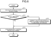
- FIG. 6 is a flowchart illustrating an example of processing (measurement method) executed in the measurement system. Since the specific processing has been described above, the detailed description will be omitted.
- Step S11 the speed of the sheet in each frame is calculated. This processing is similar to the processing in Step S1 in FIG. 3 described above.
- Step S12 it is determined whether or not an abnormal difference has been detected.
- the detector 43 of the synchronization control unit 4 detects the abnormal difference.
- the processing proceeds to Step S13. Otherwise (Step S12: No), the processing proceeds to Step S14.
- Step S13 the calculated speed of the sheet in the frame corresponding to the abnormal difference is corrected.
- the speed corrector 44 of the synchronization control unit 4 corrects the calculated speed V of the sheet 9 in the frame 1 corresponding to the abnormal difference on the basis of the calculated speeds V of the sheet 9 in the other frames 1 or the representative speed. Thereafter, the processing proceeds to Step S14.
- Step S14 the respective frames are synchronously controlled. This processing is similar to the processing in Step S2 in FIG. 3 described above.
- the synchronization control unit 4 acquires the encoder signal ES from each roller 2 arranged near each frame 1 has been described as an example.
- the speed of the sheet 9 in each frame 1 may be manually input by the operator or the like at the operator station 3 and transmitted to the synchronization control unit 4.
- the speed of the sheet 9 may be input using not only the absolute value of the speed but also the speed of the sheet 9 in another frame 1, a speed difference from a predetermined reference speed, a speed ratio, and the like. Since the speed and the extension of the sheet vary depending on the brand (the material, the measurement range, and the like), the speed may be set and managed for each brand.
- the case where the thickness of the sheet 9 is measured by the measurement system 100 has been described as an example.
- the thickness of the sheet 9 but also various factors related to the sheet 9, such as basis weight and weight, may be measured by the measurement system 100.
- the frame 1 has a ring shape as illustrated in FIG. 2 and scans and measures the sheet 9 passing through the inside has been described as an example. Not only such a configuration but also any measurement means capable of scanning and measuring the sheet 9 may be used as the frame 1 in the present disclosure.
- the measurement system 100 includes the plurality of frames 1 each of which scans and measures the sheet 9 being conveyed, and the synchronization control unit 4 which synchronously controls each of the frames 1.
- the synchronization control unit 4 includes the speed calculator 41 which calculates the calculated speed of the sheet 9 in each of the frames 1, and the controller 42 which controls each of the frames 1 so that each of the frames 1 scans and measures the same position of the sheet 9 on the basis of the calculated speed V of the sheet 9 in each of the frames 1 calculated by the speed calculator 41.
- the frames 1 are controlled so that the frames 1 scan and measure the same position of the sheet 9 on the basis of the calculated speeds V of the sheet 9 in the frames 1. Accordingly, it is possible to reduce lowering of accuracy of synchronization control for the plurality of frames 1.
- the plurality of frames 1 may include the former frame 1 and the latter frame 1 arranged in order in the conveying direction of the sheet 9, and the controller 42 may calculate the delay time T of scanning of the latter frame 1 with respect to scanning of the former frame 1 on the basis of the path length L between the former frame 1 and the latter frame 1, the calculated speed V of the sheet 9 in the former frame 1, and the calculated speed V of the sheet 9 in the latter frame 1, and control scanning timing of the latter frame 1 on the basis of the delay time T calculated.
- the controller 42 may calculate the delay time T by dividing the path length L by the average speed of the calculated speed V of the sheet 9 in the former frame 1 and the calculated speed V of the sheet 9 in the latter frame 1. For example, by calculating the delay time T in this manner, the respective frames 1 can be synchronously controlled.
- the synchronization control unit 4 may include the detector 43 which detects the abnormal difference between the calculated speeds V of the sheet 9 in the frames 1 calculated by the speed calculator 41, and the speed corrector 44 which corrects the calculated speed V of the sheet 9 in the frame 1 corresponding to the abnormal difference detected by the detector 43 out of the calculated speeds V of the sheet 9 in the frames 1 calculated by the speed calculator 41.
- the speed corrector 44 may correct the calculated speed V of the sheet 9 in the frame 1 corresponding to the abnormal difference on the basis of the calculated speed V of the sheet 9 in another frame 1.
- the speed corrector 44 may correct the calculated speed V of the sheet 9 in the frame 1 corresponding to the abnormal difference on the basis of the path length L between the frame 1 corresponding to the abnormal difference and another frame 1 and the calculated speed V of the sheet 9 in the other frame 1.
- the calculated speed V of the sheet 9 in the frame 1 corresponding to the abnormal difference can be corrected.
- the speed calculator 41 may calculate the speed V of the sheet 9 in each of the frames 1 on the basis of the encoder signal ES from the encoder of the roller 2 disposed near each of the frames 1 and constituting a conveying means of the sheet 9. For example, in this manner, the calculated speed V of the sheet 9 in each of the frames 1 can be calculated.
- the measurement method described with reference to FIGS. 3 , 6 , and the like is also one of the disclosed technologies.
- the measurement method is a measurement method using the plurality of frames 1 each of which scans and measures the sheet 9 being conveyed, and includes calculating the speed of the sheet 9 in each of the frames 1 (Step S1 or Step S11), and controlling each of the frames 1 so that each of the frames 1 scans and measures the same position of the sheet 9 on the basis of the calculated speed of the sheet 9 in each of the frames 1 calculated (Step S2 or Step S14).
Landscapes
- Physics & Mathematics (AREA)
- General Physics & Mathematics (AREA)
- Electromagnetism (AREA)
- Engineering & Computer Science (AREA)
- Power Engineering (AREA)
- Controlling Sheets Or Webs (AREA)
Abstract
Description
- The present invention relates to a measurement system and a measurement method.
- It is known to synchronously control a plurality of frames for scanning and measuring a sheet being conveyed (see, for example, Patent Literature 1).
- Patent Literature 1:
JP 7-204565 A - For example, there is a case where the sheet extends at the time of conveyance, and the speed of the sheet differs depending on the frame. If this point is not taken into consideration, the synchronization is lost, and the accuracy of the synchronization control is lowered.
- One aspect of the present invention makes it possible to reduce lowering of accuracy of synchronization control for a plurality of frames.
- According to one aspect, a measurement system includes a plurality of frames each of which scans and measures a sheet being conveyed, and a synchronization control unit which synchronously controls each of the frames, wherein the synchronization control unit includes a speed calculator which calculates a speed of the sheet in each of the frames, and a controller which controls each of the frames so that each of the frames scans and measures an equal position of the sheet on a basis of a calculated speed of the sheet in each of the frames calculated by the speed calculator.
- According to one aspect, a measurement method using a plurality of frames each of which scans and measures a sheet being conveyed, the measurement method includes calculating a speed of the sheet in each of the frames, and controlling each of the frames so that each of the frames scans and measures an equal position of the sheet on a basis of a calculated speed of the sheet in each of the frames calculated.
- According to the present invention, it is possible to reduce lowering of accuracy of synchronization control for a plurality of frames.
-
-
FIG. 1 is a diagram illustrating an example of a schematic configuration of a measurement system according to a first embodiment. -
FIG. 2 is a diagram illustrating an example of a schematic configuration of a frame. -
FIG. 3 is a flowchart illustrating an example of processing (measurement method) executed in the measurement system. -
FIG. 4 is a diagram illustrating an example of functional blocks of a synchronization control unit used in a measurement system according to a second embodiment. -
FIG. 5 is a graph illustrating an example of detection of an abnormal difference. -
FIG. 6 is a flowchart illustrating an example of processing (measurement method) executed in the measurement system. - Hereinbelow, embodiments will be described with reference to the drawings. The same elements are denoted by the same reference signs, and redundant description will be omitted as appropriate.
-
FIG. 1 is a diagram illustrating an example of a schematic configuration of a measurement system according to a first embodiment. Ameasurement system 100 measures asheet 9 being conveyed. Examples of thesheet 9 include paper, resin, and a battery electrode sheet. For example, thesheet 9 during the manufacturing process is measured by themeasurement system 100. Examples of a process included in the production process are a coating process and a drying process. Themeasurement system 100 includes a plurality offrames 1, a plurality ofrollers 2, anoperator station 3 and asynchronization control unit 4. - Each of the plurality of
frames 1 is disposed such that thesheet 9 passes through the inside of the frame, and scans and measures thesheet 9 being conveyed. A sensor head is used for the measurement. In this example, theframe 1 includes asensor head 11 and asensor head 12. Description will be given with reference toFIG. 2 as well. -
FIG. 2 is a diagram illustrating an example of a schematic configuration of the frame. Theframe 1 has a ring shape through which thesheet 9 can pass. Such aframe 1 is also referred to as an O-shaped frame or the like. Thesensor head 11 and thesensor head 12 are attached to theframe 1 and supported. - The
sensor head 11 and thesensor head 12 scan thesheet 9 by moving in theframe 1 in a direction intersecting with (for example, a direction orthogonal to) the conveying direction of thesheet 9. The scanned position on thesheet 9 is referred to as a scannedposition 9P, and is schematically illustrated. Thesensor head 11 and thesensor head 12 are arranged so as to be located on opposite sides with thesheet 9 interposed therebetween, and move together so as to scan the entire width of thesheet 9 while repeating forward movement and backward movement in a state where the positional relationship is fixed. For example, thesensor head 11 and thesensor head 12 are driven by, for example, a not-illustrated actuator. - For example, a radiation source such as β rays and X-rays is provided in the
sensor head 11. A radiation detector that detects radiation from thesensor head 11 is mounted on thesensor head 12. Radiation from thesensor head 11 is transmitted through thesheet 9 and is detected by thesensor head 12. By doing so, the transmission amount and the attenuation amount (which may be the transmittance and the attenuation rate) of the radiation transmitted through thesheet 9 are detected. For example, the thickness of thesheet 9 is calculated on the basis of a calibration curve indicating a relationship between the transmittance or the like of thesheet 9 and the thickness of thesheet 9. The thickness of thesheet 9 can be measured. - Returning to
FIG. 1 , as the plurality offrames 1, a frame 1-1 to a frame 1-5 are exemplified. Thesheet 9 is conveyed so as to pass through the frame 1-1 to the frame 1-5 in this order. For example, the thickness of thesheet 9 in a state before coating is measured by the frame 1-1. A coater C-1 applies a coating material to the front surface of thesheet 9. The frame 1-2 measures the thickness of thesheet 9 in a state where the coating material is applied to the front surface. Thereafter, thesheet 9 passes through a drying furnace D-1. The frame 1-3 measures the thickness of thesheet 9 in a dried state. A coater C-2 applies a coating material to the rear surface of thesheet 9. The frame 1-4 measures the thickness of thesheet 9 in a state where the coating material is applied to the rear surface. Thereafter, thesheet 9 passes through a drying furnace D-2. The frame 1-5 measures the thickness of thesheet 9 in a dried state. - The distance between the
frames 1 in the conveying direction of thesheet 9 is referred to as a path length L. Examples of the path length L include a path length L12 between the frame 1-1 and the frame 1-2, a path length L23 between the frame 1-2 and the frame 1-3, a path length L34 between the frame 1-3 and the frame 1-4, and a path length L45 between the frame 1-4 and the frame 1-5. - The
roller 2 is one of the components of a conveying device for thesheet 9. An example of the conveying device includes a conveyor. Theroller 2 rotates in accordance with the movement of thesheet 9 conveyed. Therollers 2, out of the plurality ofrollers 2, located near the frame 1-1 to the frame 1-5 are referred to as a roller 2-1 to a roller 2-5, respectively, and are illustrated in the figure. - The rotation of at least some of the plurality of
rollers 2 is detected by an encoder. The signal indicating the detection result is referred to as an encoder signal ES. The encoder signal ES is transmitted from the encoder of theroller 2 to thesynchronization control unit 4. In the example illustrated inFIG. 1 , the rotation of at least the roller 2-1 to the roller 2-5 is detected by the encoder. The encoder signals ES of the roller 2-1 to the roller 2-5 are referred to as an encoder signal ES-1 to an encoder signal ES-5, respectively, and are illustrated in the figure. - The
operator station 3 acquires a measurement result in eachframe 1, specifically, data of the thickness of thesheet 9. The measurement result is displayed to the operator by, for example, a monitor. A necessary operation is performed according to the measurement result. For example, parameters of the coater C-1, the coater C-2, the drying furnace D-1, the drying furnace D-2, and the like are adjusted so that the thickness of thesheet 9 becomes a target thickness. - The
synchronization control unit 4 synchronously controls the respective frames 1. The functional blocks of thesynchronization control unit 4 are also illustrated inFIG. 1 . In this example, thesynchronization control unit 4 includes aspeed calculator 41 and acontroller 42. - The
speed calculator 41 calculates the speed of thesheet 9 in eachframe 1. In the example illustrated inFIG. 1 , thespeed calculator 41 calculates the speed of thesheet 9 in eachframe 1 on the basis of the encoder signal ES from theroller 2 near theframe 1. For example, on the basis of the rotating speed of theroller 2 grasped from the encoder signal ES, the speed of thesheet 9 in thecorresponding frame 1 is calculated. In the example illustrated inFIG. 1 , on the basis of the encoder signal ES-1 to the encoder signal ES-5, the speeds of thesheet 9 in the frame 1-1 to the frame 1-5 are calculated. Hereinbelow, the speed of thesheet 9 calculated by thespeed calculator 41 is also referred to as a calculated speed V. - Here, the calculated speeds V in the
respective frames 1 may be different from each other. One of the factors is the extension of thesheet 9 being conveyed. Depending on the material or the like of thesheet 9, thesheet 9 extends at the time of conveyance. As described below, in the present embodiment, even in a case where the calculated speeds V in therespective frames 1 are different due to the extension or the like of thesheet 9, theframes 1 are appropriately synchronously controlled. - The
controller 42 controls eachframe 1 so that theframe 1 scans and measures the same position of thesheet 9 on the basis of the calculated speed V of thesheet 9 in theframe 1. In other words, the scanning timing of eachframe 1, that is, the driving timings of thesensor head 11 and thesensor head 12 are controlled so that the scannedposition 9P of thesheet 9 in eachframe 1 becomes the same. - Of the plurality of
frames 1, twoframes 1 arranged in order in the conveying direction of thesheet 9 will be described as examples. On the basis of the path length L between theformer frame 1 and thelatter frame 1 out of the twoframes 1, the calculated speed V in theformer frame 1, and the calculated speed V in thelatter frame 1, thecontroller 42 calculates delay time T of scanning of thelatter frame 1 with respect to scanning of theformer frame 1. - For example, the
controller 42 calculates the delay time T by dividing the path length L between theformer frame 1 and thelatter frame 1 by the average speed of the calculated speed V of thesheet 9 in theformer frame 1 and the calculated speed V of thesheet 9 in thelatter frame 1. - Specifically, description will be provided using the frame 1-1 and the frame 1-2 as examples of the
former frame 1 and thelatter frame 1. The calculated speed V of thesheet 9 in the frame 1-1 is defined as a calculated speed V1. The calculated speed V of thesheet 9 in the frame 1-2 is defined as a calculated speed V2. The path length L between the frame 1-1 and the frame 1-2 is defined as the path length L12 as described above. The delay time T of scanning of the frame 1-2 with respect to scanning of the frame 1-1 is defined as delay time T12. In this case, thecontroller 42 calculates the delay time T12 on the basis of Equation (1) described below, for example.
- Similarly, for example, delay time T23 of scanning of the frame 1-3 with respect to scanning of the frame 1-2 is calculated. Delay time T34 of scanning of the frame 1-4 with respect to scanning of the frame 1-3 is calculated. Delay time T45 of scanning of the frame 1-5 with respect to scanning of the frame 1-4 is calculated.
- The
controller 42 controls the scanning timing of thelatter frame 1 on the basis of the calculated delay time T. Thecontroller 42 controls the scanning timing of thelatter frame 1 so that the scanning of thelatter frame 1 is delayed by the delay time T further than the scanning of theformer frame 1. For example, the scanning timing of the frame 1-2 is controlled so that the scanning timing of the frame 1-2 is delayed by the delay time T12 further than the scanning timing of the frame 1-1. The scanning timing of the frame 1-3 is controlled so that the scanning timing of the frame 1-3 is delayed by the delay time T23 further than the scanning timing of the frame 1-2. The scanning timing of the frame 1-4 is controlled so that the scanning timing of the frame 1-4 is delayed by the delay time T34 further than the scanning timing of the frame 1-3. The scanning timing of the frame 1-5 is controlled so that the scanning timing of the frame 1-5 is delayed by the delay time T45 further than the scanning timing of the frame 1-4. - In the example illustrated in
FIG. 1 , thecontroller 42 controls eachframe 1 by transmitting a command signal CS to theframe 1. The command signals CS transmitted to the frame 1-1 to the frame 1-5 are referred to as a command signal CS-1 to a command signal CS-5, respectively, and are illustrated in the figure. Eachframe 1 drives thesensor head 11 and thesensor head 12 on the basis of the command signal CS from thecontroller 42 of thesynchronization control unit 4. Therespective frames 1 each drive thesensor head 11 and thesensor head 12 so that theframes 1 scan and measure the same position of thesheet 9. - According to the
measurement system 100 described above, even in a case where the calculated speeds V in therespective frames 1 are different due to, for example, the extension of thesheet 9 being conveyed, theframes 1 are controlled so that theframes 1 scan and measure the same position of thesheet 9 on the basis of the calculated speeds V of thesheet 9 in theframes 1. The thickness of the same scannedposition 9P of thesheet 9 can be measured accurately. -
FIG. 3 is a flowchart illustrating an example of processing (measurement method) executed in the measurement system. Since the specific processing has been described above, the detailed description will be omitted. - In Step S1, the speed of the sheet in each frame is calculated. The
speed calculator 41 of thesynchronization control unit 4 calculates the speed of thesheet 9 in eachframe 1 on the basis of the encoder signal ES from theroller 2 near theframe 1. - In Step S2, the respective frames are synchronously controlled. The
controller 42 of thesynchronization control unit 4 controls eachframe 1 so that theframe 1 scans and measures the same position of thesheet 9 on the basis of the calculated speed V of thesheet 9 in theframe 1. - In a case where slippage of the
sheet 9 being conveyed occurs, the calculated speed V of thesheet 9 in someframes 1 may be different from the actual speed of thesheet 9. In such a case, a measure according to the second embodiment may be taken. -
FIG. 4 is a diagram illustrating an example of functional blocks of a synchronization control unit used in a measurement system according to a second embodiment. Thesynchronization control unit 4 further includes a detector 43 and aspeed corrector 44. - The detector 43 detects an abnormal difference between the speeds of the
sheet 9 in theframes 1, that is, the calculated speeds V in theframes 1, calculated by thespeed calculator 41. Several specific examples of the detection method will be described. - The detector 43 may detect the abnormal difference in a case where the difference between the calculated speeds V in the
frames 1 is larger than a threshold value. In this case, theframe 1 having the calculated speed V that is far (for example, farthest) from the calculated speeds V in theother frames 1 may be detected as theframe 1 corresponding to the abnormal difference. - The detector 43 may detect the abnormal difference in a case where the difference of the calculated speed V in the
middle frame 1, out of the threeframes 1 arranged in order in the conveyance direction of thesheet 9, from the calculated speed V in theformer frame 1 and the difference thereof from the calculated speed V in thelatter frame 1 are each larger than a threshold value. In this case, themiddle frame 1 may be detected as theframe 1 corresponding to the abnormal difference. -
FIG. 5 is a graph illustrating an example of detection of the abnormal difference. The horizontal axis of the graph corresponds to the frame 1-1 to the frame 1-5. The vertical axis of the graph indicates the calculated speed V of thesheet 9 in each of theframes 1. - The four kinds of plotted point illustrate four patterns of measurement results. Each of the alternate long and short dash lines virtually indicates the assumed calculated speeds V of the
sheet 9 in the respective frames 1. The extension of thesheet 9 is taken into consideration, and the assumed calculated speed V increases in order from the frame 1-1 to the frame 1-5. - The rhombus plotted points illustrate the measurement result of a normal pattern. The calculated speeds V of the
sheet 9 in all theframes 1 follow the assumed calculated speeds V. The X plotted points, the square plotted points, and the triangle plotted points indicate the measurement results of abnormal patterns. Each of the patterns indicates an abnormal pattern in which the calculated speed V of thesheet 9 in at least oneframe 1 is significantly far from the assumed calculated speed V. - In an
abnormal pattern 1, as indicated by an outlined arrow AR1, the difference of the calculated speed V in the frame 1-5 from the calculated speed V in anotherframe 1 is larger than a threshold value, and the abnormal difference is detected. In addition, the frame 1-5 is detected as theframe 1 corresponding to the abnormal difference. - In an
abnormal pattern 2 and anabnormal pattern 3, as indicated by outlined arrows AR2 and AR3, the differences of the calculated speed V of thesheet 9 in the frame 1-3 from the calculated speeds V in the frame 1-2 and the frame 1-4 arranged before and after the frame 1-3 are larger than the threshold value, and the abnormal difference is detected. In addition, the frame 1-3 is detected as theframe 1 corresponding to the abnormal difference. - The abnormal difference detected in the above-described
abnormal pattern 1 may occur in a case where slippage of thesheet 9 occurs in the roller 2-5 corresponding to the frame 1-5. The abnormal difference detected in each of theabnormal patterns sheet 9 occurs in the roller 2-3 corresponding to the frame 1-3. Therefore, it can be said that the detection of the abnormal difference is detection of occurrence of slippage of thesheet 9. - Returning to
FIG. 4 , thespeed corrector 44 corrects the calculated speed V of thesheet 9 in theframe 1 corresponding to the abnormal difference detected by the detector 43 out of the calculated speeds V in therespective frames 1 calculated by thespeed calculator 41. - In one embodiment, the
speed corrector 44 corrects the calculated speed V of thesheet 9 in theframe 1 corresponding to the abnormal difference on the basis of the calculated speed V in anotherframe 1. Thespeed corrector 44 calculates the speed of thesheet 9 in theframe 1 corresponding to the abnormal difference on the basis of the calculated speed V in anotherframe 1. Thespeed corrector 44 corrects the calculated speed V of thesheet 9 in theframe 1 corresponding to the abnormal difference so that the speed calculated becomes the calculated speed V of thesheet 9 in theframe 1. It can also be said that the calculated speed V of thesheet 9 in theframe 1 corresponding to the abnormal difference calculated by thespeed calculator 41 is calculated again and updated by thespeed corrector 44. - The
speed corrector 44 may correct the calculated speed V of thesheet 9 in theframe 1 corresponding to the abnormal difference on the basis of the path length L between theframe 1 corresponding to the abnormal difference and anotherframe 1 and the calculated speed V of thesheet 9 in theother frame 1. - Specifically, description will be provided using the frame 1-1, the frame 1-2, and the frame 1-3 as examples. It is assumed that the frame 1-2 is the
frame 1 corresponding to the abnormal difference. The calculated speed V of thesheet 9 in the frame 1-1 is defined as a calculated speed V1. The calculated speed V of thesheet 9 in the frame 1-3 is defined as a calculated speed V3. The path length L between the frame 1-1 and the frame 1-2 is defined as the path length L12 as described above. The path length L between the frame 1-2 and the frame 1-3 is defined as the path length L23 as described above. In this case, thecontroller 42 calculates the speed V2 of thesheet 9 in the frame 1-2 on the basis of, for example, Equation (2) described below.
- The
speed corrector 44 corrects the calculated speed V of thesheet 9 in the frame 1-2 so that the calculated speed V of thesheet 9 in the frame 1-2 becomes the speed V2 calculated as described above. - Note that the
speed corrector 44 may correct the calculated speed V of thesheet 9 in theframe 1 corresponding to the abnormal difference on the basis of a representative speed of the entire conveying device instead of the calculated speeds V in the other frames 1. The representative speed may be a speed calculated on the basis of the encoder signal ES from a freely-selectedroller 2 out of the plurality ofrollers 2. Thespeed corrector 44 may correct the calculated speed V of thesheet 9 in theframe 1 corresponding to the abnormal difference so that the representative speed becomes the calculated speed V of thesheet 9 in theframe 1. - The
controller 42 controls eachframe 1 so that theframe 1 scans and measures the same position of thesheet 9 on the basis of the calculated speed V in theframe 1 after being corrected by thespeed corrector 44 as necessary. With this configuration, for example, even in a case where slippage of thesheet 9 being conveyed occurs and the calculated speed V of thesheet 9 in acertain frame 1 is different from the actual speed of thesheet 9, theframes 1 are controlled so that theframes 1 scan and measure the same position of thesheet 9 on the basis of the corrected calculated speed V. The thickness of the same scannedposition 9P of thesheet 9 can be measured accurately. - Note that the operator or the like may be notified, by the
operator station 3, of the abnormal difference detected by the detector 43. -
FIG. 6 is a flowchart illustrating an example of processing (measurement method) executed in the measurement system. Since the specific processing has been described above, the detailed description will be omitted. - In Step S11, the speed of the sheet in each frame is calculated. This processing is similar to the processing in Step S1 in
FIG. 3 described above. - In Step S12, it is determined whether or not an abnormal difference has been detected. In a case where there is an abnormal difference between the calculated speeds V of the
sheet 9 in theframes 1 calculated in Step S11 described above, the detector 43 of thesynchronization control unit 4 detects the abnormal difference. In a case where the abnormal difference is detected (Step S12: Yes), the processing proceeds to Step S13. Otherwise (Step S12: No), the processing proceeds to Step S14. - In Step S13, the calculated speed of the sheet in the frame corresponding to the abnormal difference is corrected. The
speed corrector 44 of thesynchronization control unit 4 corrects the calculated speed V of thesheet 9 in theframe 1 corresponding to the abnormal difference on the basis of the calculated speeds V of thesheet 9 in theother frames 1 or the representative speed.
Thereafter, the processing proceeds to Step S14. - In Step S14, the respective frames are synchronously controlled. This processing is similar to the processing in Step S2 in
FIG. 3 described above. - The disclosed technology is not limited to the above embodiments. Several modification examples will be described.
- In the above embodiments, the case where the
synchronization control unit 4 acquires the encoder signal ES from eachroller 2 arranged near eachframe 1 has been described as an example. However, such acquisition of the encoder signal ES is not essential. For example, the speed of thesheet 9 in each frame 1 (corresponding to the calculated speed V) may be manually input by the operator or the like at theoperator station 3 and transmitted to thesynchronization control unit 4. The speed of thesheet 9 may be input using not only the absolute value of the speed but also the speed of thesheet 9 in anotherframe 1, a speed difference from a predetermined reference speed, a speed ratio, and the like. Since the speed and the extension of the sheet vary depending on the brand (the material, the measurement range, and the like), the speed may be set and managed for each brand. - In the above embodiments, the case where the thickness of the
sheet 9 is measured by themeasurement system 100 has been described as an example. However, not only the thickness of thesheet 9 but also various factors related to thesheet 9, such as basis weight and weight, may be measured by themeasurement system 100. - In the above embodiments, the case where the
frame 1 has a ring shape as illustrated inFIG. 2 and scans and measures thesheet 9 passing through the inside has been described as an example. Not only such a configuration but also any measurement means capable of scanning and measuring thesheet 9 may be used as theframe 1 in the present disclosure. - The technology described above is specified as follows, for example. One of the disclosed technologies is the
measurement system 100. As described with reference toFIG. 1 and the like, themeasurement system 100 includes the plurality offrames 1 each of which scans and measures thesheet 9 being conveyed, and thesynchronization control unit 4 which synchronously controls each of theframes 1. Thesynchronization control unit 4 includes thespeed calculator 41 which calculates the calculated speed of thesheet 9 in each of theframes 1, and thecontroller 42 which controls each of theframes 1 so that each of theframes 1 scans and measures the same position of thesheet 9 on the basis of the calculated speed V of thesheet 9 in each of theframes 1 calculated by thespeed calculator 41. - According to the
measurement system 100 described above, even in a case where the calculated speeds V in therespective frames 1 are different due to, for example, the extension of thesheet 9 being conveyed, theframes 1 are controlled so that theframes 1 scan and measure the same position of thesheet 9 on the basis of the calculated speeds V of thesheet 9 in theframes 1. Accordingly, it is possible to reduce lowering of accuracy of synchronization control for the plurality offrames 1. - As described with reference to
FIG. 1 ,Equation 1, and the like, the plurality offrames 1 may include theformer frame 1 and thelatter frame 1 arranged in order in the conveying direction of thesheet 9, and thecontroller 42 may calculate the delay time T of scanning of thelatter frame 1 with respect to scanning of theformer frame 1 on the basis of the path length L between theformer frame 1 and thelatter frame 1, the calculated speed V of thesheet 9 in theformer frame 1, and the calculated speed V of thesheet 9 in thelatter frame 1, and control scanning timing of thelatter frame 1 on the basis of the delay time T calculated. Thecontroller 42 may calculate the delay time T by dividing the path length L by the average speed of the calculated speed V of thesheet 9 in theformer frame 1 and the calculated speed V of thesheet 9 in thelatter frame 1. For example, by calculating the delay time T in this manner, therespective frames 1 can be synchronously controlled. - As described with reference to
FIG. 4 and the like, thesynchronization control unit 4 may include the detector 43 which detects the abnormal difference between the calculated speeds V of thesheet 9 in theframes 1 calculated by thespeed calculator 41, and thespeed corrector 44 which corrects the calculated speed V of thesheet 9 in theframe 1 corresponding to the abnormal difference detected by the detector 43 out of the calculated speeds V of thesheet 9 in theframes 1 calculated by thespeed calculator 41. With this configuration, for example, even in a case where slippage of thesheet 9 being conveyed occurs and the calculated speed V of thesheet 9 in acertain frame 1 is different from the actual speed of thesheet 9, therespective frames 1 can be synchronously controlled. - As described with reference to
FIG. 4 ,Equation 2, and the like, thespeed corrector 44 may correct the calculated speed V of thesheet 9 in theframe 1 corresponding to the abnormal difference on the basis of the calculated speed V of thesheet 9 in anotherframe 1. For example, thespeed corrector 44 may correct the calculated speed V of thesheet 9 in theframe 1 corresponding to the abnormal difference on the basis of the path length L between theframe 1 corresponding to the abnormal difference and anotherframe 1 and the calculated speed V of thesheet 9 in theother frame 1. For example, in this manner, the calculated speed V of thesheet 9 in theframe 1 corresponding to the abnormal difference can be corrected. - The
speed calculator 41 may calculate the speed V of thesheet 9 in each of theframes 1 on the basis of the encoder signal ES from the encoder of theroller 2 disposed near each of theframes 1 and constituting a conveying means of thesheet 9. For example, in this manner, the calculated speed V of thesheet 9 in each of theframes 1 can be calculated. - The measurement method described with reference to
FIGS. 3 ,6 , and the like is also one of the disclosed technologies. The measurement method is a measurement method using the plurality offrames 1 each of which scans and measures thesheet 9 being conveyed, and includes calculating the speed of thesheet 9 in each of the frames 1 (Step S1 or Step S11), and controlling each of theframes 1 so that each of theframes 1 scans and measures the same position of thesheet 9 on the basis of the calculated speed of thesheet 9 in each of theframes 1 calculated (Step S2 or Step S14). With such a measurement method as well, as described above, it is possible to reduce lowering of accuracy of synchronization control for the plurality offrames 1. -
- 100
- MEASUREMENT SYSTEM
- 1
- FRAME
- 11
- SENSOR HEAD
- 12
- SENSOR HEAD
- 2
- ROLLER
- 3
- OPERATOR STATION
- 4
- SYNCHRONIZATION CONTROL UNIT
- 41
- SPEED CALCULATOR
- 42
- CONTROLLER
- 43
- DETECTOR
- 44
- SPEED CORRECTOR
- 9
- SHEET
- 9P
- SCANNED POSITION
Claims (8)
- A measurement system comprising:a plurality of frames each of which scans and measures a sheet being conveyed; anda synchronization control unit which synchronously controls each of the frames,wherein the synchronization control unit includesa speed calculator which calculates a speed of the sheet in each of the frames, anda controller which controls each of the frames so that each of the frames scans and measures an equal position of the sheet on a basis of a calculated speed of the sheet in each of the frames calculated by the speed calculator.
- The measurement system according to claim 1, wherein the plurality of frames include a former frame and a latter frame arranged in order in a conveying direction of the sheet, and
wherein the controller calculates delay time of scanning of the latter frame with respect to scanning of the former frame on a basis of a path length between the former frame and the latter frame, the calculated speed of the sheet in the former frame, and the calculated speed of the sheet in the latter frame, and controls scanning timing of the latter frame on a basis of the delay time calculated. - The measurement system according to claim 2, wherein the controller calculates the delay time by dividing the path length by an average speed of the calculated speed of the sheet in the former frame and the calculated speed of the sheet in the latter frame.
- The measurement system according to any one of claims 1 to 3, wherein the synchronization control unit includesa detector which detects an abnormal difference between the calculated speeds of the sheet in the frames calculated by the speed calculator, anda speed corrector which corrects the calculated speed of the sheet in the frame corresponding to the abnormal difference detected by the detector out of the calculated speeds of the sheet in the frames calculated by the speed calculator.
- The measurement system according to claim 4, wherein the speed corrector corrects the calculated speed of the sheet in the frame corresponding to the abnormal difference on a basis of the calculated speed of the sheet in a different frame.
- The measurement system according to claim 5, wherein the speed corrector corrects the calculated speed of the sheet in the frame corresponding to the abnormal difference on a basis of the path length between the frame corresponding to the abnormal difference and a different frame and the calculated speed of the sheet in the different frame.
- The measurement system according to any one of claims 1 to 6, wherein the speed calculator calculates the speed of the sheet in each of the frames on a basis of an encoder signal from an encoder of a roller disposed near each of the frames and constituting a conveying means of the sheet.
- A measurement method using a plurality of frames each of which scans and measures a sheet being conveyed, the measurement method comprising:calculating a speed of the sheet in each of the frames; andcontrolling each of the frames so that each of the frames scans and measures an equal position of the sheet on a basis of a calculated speed of the sheet in each of the frames calculated.
Applications Claiming Priority (2)
| Application Number | Priority Date | Filing Date | Title |
|---|---|---|---|
| JP2022057256A JP7468564B2 (en) | 2022-03-30 | 2022-03-30 | Measurement system and method |
| PCT/JP2023/011098 WO2023189889A1 (en) | 2022-03-30 | 2023-03-22 | Measurement system and measurement method |
Publications (2)
| Publication Number | Publication Date |
|---|---|
| EP4502621A1 true EP4502621A1 (en) | 2025-02-05 |
| EP4502621A4 EP4502621A4 (en) | 2026-03-25 |
Family
ID=88201240
Family Applications (1)
| Application Number | Title | Priority Date | Filing Date |
|---|---|---|---|
| EP23779903.6A Pending EP4502621A4 (en) | 2022-03-30 | 2023-03-22 | MEASURING SYSTEM AND MEASURING METHOD |
Country Status (6)
| Country | Link |
|---|---|
| US (1) | US20250216410A1 (en) |
| EP (1) | EP4502621A4 (en) |
| JP (1) | JP7468564B2 (en) |
| KR (1) | KR20240152927A (en) |
| CN (1) | CN118974515A (en) |
| WO (1) | WO2023189889A1 (en) |
Families Citing this family (1)
| Publication number | Priority date | Publication date | Assignee | Title |
|---|---|---|---|---|
| JP2025042125A (en) | 2023-09-14 | 2025-03-27 | 株式会社Aescジャパン | Battery pack |
Family Cites Families (4)
| Publication number | Priority date | Publication date | Assignee | Title |
|---|---|---|---|---|
| JP3106453B2 (en) | 1994-01-14 | 2000-11-06 | 横河電機株式会社 | Sheet manufacturing machine measurement control system |
| JP2009184309A (en) | 2008-02-08 | 2009-08-20 | Riso Kagaku Corp | Plate making equipment |
| DE102012224228A1 (en) | 2012-12-21 | 2014-06-26 | Robert Bosch Gmbh | Method for wet coating of substrate used in manufacture of lithium-ion battery cell, involves measuring layer thicknesses of coating layer on substrate, and independently regulating pressure in each of the first nozzle by second nozzle |
| JP6204697B2 (en) | 2013-05-16 | 2017-09-27 | 住友化学株式会社 | Defect inspection system |
-
2022
- 2022-03-30 JP JP2022057256A patent/JP7468564B2/en active Active
-
2023
- 2023-03-22 US US18/851,184 patent/US20250216410A1/en active Pending
- 2023-03-22 CN CN202380031618.1A patent/CN118974515A/en active Pending
- 2023-03-22 KR KR1020247032104A patent/KR20240152927A/en active Pending
- 2023-03-22 WO PCT/JP2023/011098 patent/WO2023189889A1/en not_active Ceased
- 2023-03-22 EP EP23779903.6A patent/EP4502621A4/en active Pending
Also Published As
| Publication number | Publication date |
|---|---|
| JP7468564B2 (en) | 2024-04-16 |
| KR20240152927A (en) | 2024-10-22 |
| CN118974515A (en) | 2024-11-15 |
| JP2023148957A (en) | 2023-10-13 |
| WO2023189889A1 (en) | 2023-10-05 |
| US20250216410A1 (en) | 2025-07-03 |
| EP4502621A4 (en) | 2026-03-25 |
Similar Documents
| Publication | Publication Date | Title |
|---|---|---|
| CN103890540B (en) | Thickness measuring system and thickness measuring method | |
| RU2664512C2 (en) | Tire component centering method | |
| JP5876116B1 (en) | X-ray inspection equipment | |
| US20250216410A1 (en) | Measurement system and measurement method | |
| US5346202A (en) | Method of monitoring the transport of print products in a printing-field machine | |
| JPH02114106A (en) | Apparatus for measuring length of sheet material | |
| US11693397B2 (en) | Method and conveying apparatus for the improved determination of the position of an object transported on the conveying apparatus | |
| CN106004006A (en) | Locating-compounding system and compounding method of patterns on two base material thin films | |
| US6601364B2 (en) | Method and device for synchronizing motion for insert feeders in an insertion system | |
| WO2012077457A1 (en) | Device for detecting conveyance amount of plate-shaped object, device for cutting plate-shaped object, method for detecting conveyance amount of plate-shaped object, device for forming cutting lines on plate-shaped object, and method for forming cutting lines on plate-shaped object. | |
| CN114472538A (en) | Signal tracking method applied to steel rolling system | |
| JP6446226B2 (en) | Surface shape measuring device for sheet-like rubber material | |
| JPH0829139A (en) | Method and device for measuring sagging amount of sheet | |
| JP6597669B2 (en) | Straightening method and apparatus for tapered steel plate | |
| JP2009085666A (en) | Sheet inclination angle measuring method, sheet inspection method, and sheet inspection apparatus | |
| JP5873242B2 (en) | Straightness inspection method | |
| KR20230032742A (en) | Edge tracking method of conveying material | |
| JP2009122973A (en) | Traveling web position control apparatus and method | |
| CN101007601A (en) | Method for transporting paper to device | |
| JPS6135085B2 (en) | ||
| JPS6244396A (en) | Control system of flying cutter | |
| JPH02212015A (en) | End cutting method in hot billet rolling | |
| JPH04116013A (en) | Automatic appearance inspecting device | |
| JP2000283727A (en) | Plywood production inspection equipment | |
| JPS6342723B2 (en) |
Legal Events
| Date | Code | Title | Description |
|---|---|---|---|
| STAA | Information on the status of an ep patent application or granted ep patent |
Free format text: STATUS: THE INTERNATIONAL PUBLICATION HAS BEEN MADE |
|
| PUAI | Public reference made under article 153(3) epc to a published international application that has entered the european phase |
Free format text: ORIGINAL CODE: 0009012 |
|
| STAA | Information on the status of an ep patent application or granted ep patent |
Free format text: STATUS: REQUEST FOR EXAMINATION WAS MADE |
|
| 17P | Request for examination filed |
Effective date: 20240926 |
|
| AK | Designated contracting states |
Kind code of ref document: A1 Designated state(s): AL AT BE BG CH CY CZ DE DK EE ES FI FR GB GR HR HU IE IS IT LI LT LU LV MC ME MK MT NL NO PL PT RO RS SE SI SK SM TR |
|
| DAV | Request for validation of the european patent (deleted) | ||
| DAX | Request for extension of the european patent (deleted) | ||
| REG | Reference to a national code |
Ref country code: DE Ref legal event code: R079 Free format text: PREVIOUS MAIN CLASS: G01P0013000000 Ipc: G01B0015020000 |
|
| A4 | Supplementary search report drawn up and despatched |
Effective date: 20260224 |
|
| RIC1 | Information provided on ipc code assigned before grant |
Ipc: G01B 15/02 20060101AFI20260218BHEP Ipc: G01G 17/02 20060101ALI20260218BHEP Ipc: G01P 3/481 20060101ALN20260218BHEP |