EP4502525A1 - Heat exchange system - Google Patents
Heat exchange system Download PDFInfo
- Publication number
- EP4502525A1 EP4502525A1 EP23780980.1A EP23780980A EP4502525A1 EP 4502525 A1 EP4502525 A1 EP 4502525A1 EP 23780980 A EP23780980 A EP 23780980A EP 4502525 A1 EP4502525 A1 EP 4502525A1
- Authority
- EP
- European Patent Office
- Prior art keywords
- low
- temperature
- temperature fluid
- heat exchanger
- flow path
- Prior art date
- Legal status (The legal status is an assumption and is not a legal conclusion. Google has not performed a legal analysis and makes no representation as to the accuracy of the status listed.)
- Pending
Links
Images




Classifications
-
- F—MECHANICAL ENGINEERING; LIGHTING; HEATING; WEAPONS; BLASTING
- F28—HEAT EXCHANGE IN GENERAL
- F28D—HEAT-EXCHANGE APPARATUS, NOT PROVIDED FOR IN ANOTHER SUBCLASS, IN WHICH THE HEAT-EXCHANGE MEDIA DO NOT COME INTO DIRECT CONTACT
- F28D9/00—Heat-exchange apparatus having stationary plate-like or laminated conduit assemblies for both heat-exchange media, the media being in contact with different sides of a conduit wall
-
- F—MECHANICAL ENGINEERING; LIGHTING; HEATING; WEAPONS; BLASTING
- F17—STORING OR DISTRIBUTING GASES OR LIQUIDS
- F17C—VESSELS FOR CONTAINING OR STORING COMPRESSED, LIQUEFIED OR SOLIDIFIED GASES; FIXED-CAPACITY GAS-HOLDERS; FILLING VESSELS WITH, OR DISCHARGING FROM VESSELS, COMPRESSED, LIQUEFIED, OR SOLIDIFIED GASES
- F17C7/00—Methods or apparatus for discharging liquefied, solidified, or compressed gases from pressure vessels, not covered by another subclass
- F17C7/02—Discharging liquefied gases
- F17C7/04—Discharging liquefied gases with change of state, e.g. vaporisation
-
- F—MECHANICAL ENGINEERING; LIGHTING; HEATING; WEAPONS; BLASTING
- F28—HEAT EXCHANGE IN GENERAL
- F28D—HEAT-EXCHANGE APPARATUS, NOT PROVIDED FOR IN ANOTHER SUBCLASS, IN WHICH THE HEAT-EXCHANGE MEDIA DO NOT COME INTO DIRECT CONTACT
- F28D21/00—Heat-exchange apparatus not covered by any of the groups F28D1/00 - F28D20/00
-
- F—MECHANICAL ENGINEERING; LIGHTING; HEATING; WEAPONS; BLASTING
- F28—HEAT EXCHANGE IN GENERAL
- F28D—HEAT-EXCHANGE APPARATUS, NOT PROVIDED FOR IN ANOTHER SUBCLASS, IN WHICH THE HEAT-EXCHANGE MEDIA DO NOT COME INTO DIRECT CONTACT
- F28D9/00—Heat-exchange apparatus having stationary plate-like or laminated conduit assemblies for both heat-exchange media, the media being in contact with different sides of a conduit wall
- F28D9/0093—Multi-circuit heat-exchangers, e.g. integrating different heat exchange sections in the same unit or heat-exchangers for more than two fluids
-
- F—MECHANICAL ENGINEERING; LIGHTING; HEATING; WEAPONS; BLASTING
- F28—HEAT EXCHANGE IN GENERAL
- F28F—DETAILS OF HEAT-EXCHANGE AND HEAT-TRANSFER APPARATUS, OF GENERAL APPLICATION
- F28F27/00—Control arrangements or safety devices specially adapted for heat-exchange or heat-transfer apparatus
- F28F27/02—Control arrangements or safety devices specially adapted for heat-exchange or heat-transfer apparatus for controlling the distribution of heat-exchange media between different channels
-
- F—MECHANICAL ENGINEERING; LIGHTING; HEATING; WEAPONS; BLASTING
- F17—STORING OR DISTRIBUTING GASES OR LIQUIDS
- F17C—VESSELS FOR CONTAINING OR STORING COMPRESSED, LIQUEFIED OR SOLIDIFIED GASES; FIXED-CAPACITY GAS-HOLDERS; FILLING VESSELS WITH, OR DISCHARGING FROM VESSELS, COMPRESSED, LIQUEFIED, OR SOLIDIFIED GASES
- F17C2205/00—Vessel construction, in particular mounting arrangements, attachments or identifications means
- F17C2205/03—Fluid connections, filters, valves, closure means or other attachments
- F17C2205/0302—Fittings, valves, filters, or components in connection with the gas storage device
- F17C2205/0323—Valves
- F17C2205/0326—Valves electrically actuated
-
- F—MECHANICAL ENGINEERING; LIGHTING; HEATING; WEAPONS; BLASTING
- F17—STORING OR DISTRIBUTING GASES OR LIQUIDS
- F17C—VESSELS FOR CONTAINING OR STORING COMPRESSED, LIQUEFIED OR SOLIDIFIED GASES; FIXED-CAPACITY GAS-HOLDERS; FILLING VESSELS WITH, OR DISCHARGING FROM VESSELS, COMPRESSED, LIQUEFIED, OR SOLIDIFIED GASES
- F17C2205/00—Vessel construction, in particular mounting arrangements, attachments or identifications means
- F17C2205/03—Fluid connections, filters, valves, closure means or other attachments
- F17C2205/0302—Fittings, valves, filters, or components in connection with the gas storage device
- F17C2205/0323—Valves
- F17C2205/0329—Valves manually actuated
-
- F—MECHANICAL ENGINEERING; LIGHTING; HEATING; WEAPONS; BLASTING
- F17—STORING OR DISTRIBUTING GASES OR LIQUIDS
- F17C—VESSELS FOR CONTAINING OR STORING COMPRESSED, LIQUEFIED OR SOLIDIFIED GASES; FIXED-CAPACITY GAS-HOLDERS; FILLING VESSELS WITH, OR DISCHARGING FROM VESSELS, COMPRESSED, LIQUEFIED, OR SOLIDIFIED GASES
- F17C2221/00—Handled fluid, in particular type of fluid
- F17C2221/01—Pure fluids
- F17C2221/012—Hydrogen
-
- F—MECHANICAL ENGINEERING; LIGHTING; HEATING; WEAPONS; BLASTING
- F17—STORING OR DISTRIBUTING GASES OR LIQUIDS
- F17C—VESSELS FOR CONTAINING OR STORING COMPRESSED, LIQUEFIED OR SOLIDIFIED GASES; FIXED-CAPACITY GAS-HOLDERS; FILLING VESSELS WITH, OR DISCHARGING FROM VESSELS, COMPRESSED, LIQUEFIED, OR SOLIDIFIED GASES
- F17C2221/00—Handled fluid, in particular type of fluid
- F17C2221/01—Pure fluids
- F17C2221/016—Noble gases (Ar, Kr, Xe)
- F17C2221/017—Helium
-
- F—MECHANICAL ENGINEERING; LIGHTING; HEATING; WEAPONS; BLASTING
- F17—STORING OR DISTRIBUTING GASES OR LIQUIDS
- F17C—VESSELS FOR CONTAINING OR STORING COMPRESSED, LIQUEFIED OR SOLIDIFIED GASES; FIXED-CAPACITY GAS-HOLDERS; FILLING VESSELS WITH, OR DISCHARGING FROM VESSELS, COMPRESSED, LIQUEFIED, OR SOLIDIFIED GASES
- F17C2221/00—Handled fluid, in particular type of fluid
- F17C2221/03—Mixtures
- F17C2221/032—Hydrocarbons
- F17C2221/033—Methane, e.g. natural gas, CNG, LNG, GNL, GNC, PLNG
-
- F—MECHANICAL ENGINEERING; LIGHTING; HEATING; WEAPONS; BLASTING
- F17—STORING OR DISTRIBUTING GASES OR LIQUIDS
- F17C—VESSELS FOR CONTAINING OR STORING COMPRESSED, LIQUEFIED OR SOLIDIFIED GASES; FIXED-CAPACITY GAS-HOLDERS; FILLING VESSELS WITH, OR DISCHARGING FROM VESSELS, COMPRESSED, LIQUEFIED, OR SOLIDIFIED GASES
- F17C2223/00—Handled fluid before transfer, i.e. state of fluid when stored in the vessel or before transfer from the vessel
- F17C2223/01—Handled fluid before transfer, i.e. state of fluid when stored in the vessel or before transfer from the vessel characterised by the phase
- F17C2223/0146—Two-phase
- F17C2223/0153—Liquefied gas, e.g. LPG, GPL
- F17C2223/0161—Liquefied gas, e.g. LPG, GPL cryogenic, e.g. LNG, GNL, PLNG
-
- F—MECHANICAL ENGINEERING; LIGHTING; HEATING; WEAPONS; BLASTING
- F17—STORING OR DISTRIBUTING GASES OR LIQUIDS
- F17C—VESSELS FOR CONTAINING OR STORING COMPRESSED, LIQUEFIED OR SOLIDIFIED GASES; FIXED-CAPACITY GAS-HOLDERS; FILLING VESSELS WITH, OR DISCHARGING FROM VESSELS, COMPRESSED, LIQUEFIED, OR SOLIDIFIED GASES
- F17C2225/00—Handled fluid after transfer, i.e. state of fluid after transfer from the vessel
- F17C2225/01—Handled fluid after transfer, i.e. state of fluid after transfer from the vessel characterised by the phase
- F17C2225/0107—Single phase
- F17C2225/0123—Single phase gaseous, e.g. CNG, GNC
-
- F—MECHANICAL ENGINEERING; LIGHTING; HEATING; WEAPONS; BLASTING
- F17—STORING OR DISTRIBUTING GASES OR LIQUIDS
- F17C—VESSELS FOR CONTAINING OR STORING COMPRESSED, LIQUEFIED OR SOLIDIFIED GASES; FIXED-CAPACITY GAS-HOLDERS; FILLING VESSELS WITH, OR DISCHARGING FROM VESSELS, COMPRESSED, LIQUEFIED, OR SOLIDIFIED GASES
- F17C2225/00—Handled fluid after transfer, i.e. state of fluid after transfer from the vessel
- F17C2225/03—Handled fluid after transfer, i.e. state of fluid after transfer from the vessel characterised by the pressure level
- F17C2225/036—Very high pressure, i.e. above 80 bars
-
- F—MECHANICAL ENGINEERING; LIGHTING; HEATING; WEAPONS; BLASTING
- F17—STORING OR DISTRIBUTING GASES OR LIQUIDS
- F17C—VESSELS FOR CONTAINING OR STORING COMPRESSED, LIQUEFIED OR SOLIDIFIED GASES; FIXED-CAPACITY GAS-HOLDERS; FILLING VESSELS WITH, OR DISCHARGING FROM VESSELS, COMPRESSED, LIQUEFIED, OR SOLIDIFIED GASES
- F17C2227/00—Transfer of fluids, i.e. method or means for transferring the fluid; Heat exchange with the fluid
- F17C2227/03—Heat exchange with the fluid
- F17C2227/0302—Heat exchange with the fluid by heating
- F17C2227/0306—Heat exchange with the fluid by heating using the same fluid
-
- F—MECHANICAL ENGINEERING; LIGHTING; HEATING; WEAPONS; BLASTING
- F17—STORING OR DISTRIBUTING GASES OR LIQUIDS
- F17C—VESSELS FOR CONTAINING OR STORING COMPRESSED, LIQUEFIED OR SOLIDIFIED GASES; FIXED-CAPACITY GAS-HOLDERS; FILLING VESSELS WITH, OR DISCHARGING FROM VESSELS, COMPRESSED, LIQUEFIED, OR SOLIDIFIED GASES
- F17C2227/00—Transfer of fluids, i.e. method or means for transferring the fluid; Heat exchange with the fluid
- F17C2227/03—Heat exchange with the fluid
- F17C2227/0302—Heat exchange with the fluid by heating
- F17C2227/0309—Heat exchange with the fluid by heating using another fluid
-
- F—MECHANICAL ENGINEERING; LIGHTING; HEATING; WEAPONS; BLASTING
- F17—STORING OR DISTRIBUTING GASES OR LIQUIDS
- F17C—VESSELS FOR CONTAINING OR STORING COMPRESSED, LIQUEFIED OR SOLIDIFIED GASES; FIXED-CAPACITY GAS-HOLDERS; FILLING VESSELS WITH, OR DISCHARGING FROM VESSELS, COMPRESSED, LIQUEFIED, OR SOLIDIFIED GASES
- F17C2227/00—Transfer of fluids, i.e. method or means for transferring the fluid; Heat exchange with the fluid
- F17C2227/03—Heat exchange with the fluid
- F17C2227/0302—Heat exchange with the fluid by heating
- F17C2227/0309—Heat exchange with the fluid by heating using another fluid
- F17C2227/0316—Water heating
-
- F—MECHANICAL ENGINEERING; LIGHTING; HEATING; WEAPONS; BLASTING
- F17—STORING OR DISTRIBUTING GASES OR LIQUIDS
- F17C—VESSELS FOR CONTAINING OR STORING COMPRESSED, LIQUEFIED OR SOLIDIFIED GASES; FIXED-CAPACITY GAS-HOLDERS; FILLING VESSELS WITH, OR DISCHARGING FROM VESSELS, COMPRESSED, LIQUEFIED, OR SOLIDIFIED GASES
- F17C2227/00—Transfer of fluids, i.e. method or means for transferring the fluid; Heat exchange with the fluid
- F17C2227/03—Heat exchange with the fluid
- F17C2227/0302—Heat exchange with the fluid by heating
- F17C2227/0309—Heat exchange with the fluid by heating using another fluid
- F17C2227/0323—Heat exchange with the fluid by heating using another fluid in a closed loop
-
- F—MECHANICAL ENGINEERING; LIGHTING; HEATING; WEAPONS; BLASTING
- F17—STORING OR DISTRIBUTING GASES OR LIQUIDS
- F17C—VESSELS FOR CONTAINING OR STORING COMPRESSED, LIQUEFIED OR SOLIDIFIED GASES; FIXED-CAPACITY GAS-HOLDERS; FILLING VESSELS WITH, OR DISCHARGING FROM VESSELS, COMPRESSED, LIQUEFIED, OR SOLIDIFIED GASES
- F17C2227/00—Transfer of fluids, i.e. method or means for transferring the fluid; Heat exchange with the fluid
- F17C2227/03—Heat exchange with the fluid
- F17C2227/0367—Localisation of heat exchange
- F17C2227/0388—Localisation of heat exchange separate
- F17C2227/0393—Localisation of heat exchange separate using a vaporiser
-
- F—MECHANICAL ENGINEERING; LIGHTING; HEATING; WEAPONS; BLASTING
- F17—STORING OR DISTRIBUTING GASES OR LIQUIDS
- F17C—VESSELS FOR CONTAINING OR STORING COMPRESSED, LIQUEFIED OR SOLIDIFIED GASES; FIXED-CAPACITY GAS-HOLDERS; FILLING VESSELS WITH, OR DISCHARGING FROM VESSELS, COMPRESSED, LIQUEFIED, OR SOLIDIFIED GASES
- F17C2250/00—Accessories; Control means; Indicating, measuring or monitoring of parameters
- F17C2250/03—Control means
- F17C2250/032—Control means using computers
-
- F—MECHANICAL ENGINEERING; LIGHTING; HEATING; WEAPONS; BLASTING
- F17—STORING OR DISTRIBUTING GASES OR LIQUIDS
- F17C—VESSELS FOR CONTAINING OR STORING COMPRESSED, LIQUEFIED OR SOLIDIFIED GASES; FIXED-CAPACITY GAS-HOLDERS; FILLING VESSELS WITH, OR DISCHARGING FROM VESSELS, COMPRESSED, LIQUEFIED, OR SOLIDIFIED GASES
- F17C2265/00—Effects achieved by gas storage or gas handling
- F17C2265/05—Regasification
-
- F—MECHANICAL ENGINEERING; LIGHTING; HEATING; WEAPONS; BLASTING
- F17—STORING OR DISTRIBUTING GASES OR LIQUIDS
- F17C—VESSELS FOR CONTAINING OR STORING COMPRESSED, LIQUEFIED OR SOLIDIFIED GASES; FIXED-CAPACITY GAS-HOLDERS; FILLING VESSELS WITH, OR DISCHARGING FROM VESSELS, COMPRESSED, LIQUEFIED, OR SOLIDIFIED GASES
- F17C2265/00—Effects achieved by gas storage or gas handling
- F17C2265/06—Fluid distribution
- F17C2265/065—Fluid distribution for refuelling vehicle fuel tanks
-
- F—MECHANICAL ENGINEERING; LIGHTING; HEATING; WEAPONS; BLASTING
- F17—STORING OR DISTRIBUTING GASES OR LIQUIDS
- F17C—VESSELS FOR CONTAINING OR STORING COMPRESSED, LIQUEFIED OR SOLIDIFIED GASES; FIXED-CAPACITY GAS-HOLDERS; FILLING VESSELS WITH, OR DISCHARGING FROM VESSELS, COMPRESSED, LIQUEFIED, OR SOLIDIFIED GASES
- F17C2270/00—Applications
- F17C2270/01—Applications for fluid transport or storage
- F17C2270/0134—Applications for fluid transport or storage placed above the ground
- F17C2270/0139—Fuel stations
-
- F—MECHANICAL ENGINEERING; LIGHTING; HEATING; WEAPONS; BLASTING
- F28—HEAT EXCHANGE IN GENERAL
- F28D—HEAT-EXCHANGE APPARATUS, NOT PROVIDED FOR IN ANOTHER SUBCLASS, IN WHICH THE HEAT-EXCHANGE MEDIA DO NOT COME INTO DIRECT CONTACT
- F28D21/00—Heat-exchange apparatus not covered by any of the groups F28D1/00 - F28D20/00
- F28D2021/0019—Other heat exchangers for particular applications; Heat exchange systems not otherwise provided for
- F28D2021/0033—Other heat exchangers for particular applications; Heat exchange systems not otherwise provided for for cryogenic applications
Definitions
- the present invention relates to a heat exchange system, in particular to a heat exchange system for transferring heat between a low-temperature fluid and a high-temperature fluid.
- Heat exchange systems for transferring heat between a low-temperature fluid and a high-temperature fluid are known in the art.
- Such a heat exchange system is disclosed in Japanese Patent Laid-Open Publication No. JP 2010-101617 , for example.
- the above Japanese Patent Laid-Open Publication No. JP 2010-101617 discloses a heat exchange device for transferring heat between a low-temperature fluid and a high-temperature fluid.
- the heat exchange device disclosed in the above Japanese Patent Laid-Open Publication No. JP 2010-101617 is a plate-fin type heat exchange device in which first passages for flowing a first fluid and second passages for flowing a second fluid are alternatively stacked on each other.
- the heat exchange device disclosed in the above Japanese Patent Laid-Open Publication No. JP 2010-101617 is particularly used in applications such as liquefaction or vaporization of flows of natural gas having large temperature differences between fluids of the natural gas.
- Patent Document 1 Japanese Patent Laid-Open Publication No. JP 2010-101617
- first and second passages are alternately stacked on each other.
- first fluid being lower temperature low-temperature fluid
- second fluid being higher temperature high-temperature fluid
- the high-temperature fluid may freeze during the transferring heat.
- the present invention is intended to solve the above problem, and one object of the present invention is to provide a heat exchange system capable of preventing, when transferring heat between a low-temperature fluid and a liquid high-temperature fluid, the high-temperature fluid from freezing.
- a heat exchange system includes a first heat exchanger for transferring heat between a low-temperature fluid and a high-temperature fluid whose temperature is higher than the low-temperature fluid; a second heat exchanger for transferring heat between flows of the low-temperature fluid; and a heater, the second heat exchanger including a first inlet configured for the low-temperature fluid to flow into, a first outlet which communicates with the first inlet, a second inlet configured for the low-temperature fluid to flow into, and a second outlet which communicates with the second inlet, wherein the second heat exchanger is configured to transfer heat between the low-temperature fluid flowing in from the first inlet and the low-temperature fluid flowing out from the first outlet and flowing in from the second inlet, the heater is provided between the first outlet and the second inlet and is configured to heat the low-temperature fluid flowing out from the first outlet, the low-temperature fluid flowing out from the second outlet can flow into the first exchanger.
- the heat exchange system includes a first heat exchanger for transferring heat between a low-temperature fluid and a high-temperature fluid; a second heat exchanger for transferring heat between flows of the low-temperature fluid; and a heater configured to heat the low-temperature fluid flowing out from the first outlet, the low-temperature fluid flowing out from the second outlet can flow into the first exchanger. Accordingly, since the low-temperature fluid is heated by the second heat exchanger before the low-temperature fluid flows into the first heat exchanger, the low-temperature fluid that flows into the first heat exchanger can be previously heated.
- the first heat exchanger serves as the heater; that the first heat exchanger including a first low-temperature side inlet configured for the low-temperature fluid to flow into; and, and a first low-temperature side outlet which communicates with the first low-temperature side inlet; that the first outlet of the second heat exchanger communicates with the first low-temperature side inlet of the first heat exchanger, that the low-temperature fluid flowing out from the first outlet can flow into the first low-temperature side inlet, flow out from the first low-temperature side outlet, and flow into the second inlet.
- the low-temperature fluid that flows out through the first outlet can be heated by the first heat exchanger, and be returned through the second inlet to the second heat exchanger.
- the low-temperature fluid that flows out through the first outlet is higher in temperature than the low-temperature fluid that flows in through the first inlet
- the low-temperature fluid that flows out through the second outlet becomes higher in temperature than the low-temperature fluid that flows in through the first inlet. That is, both the low-temperature fluid that flows out through the first outlet and flows into the first heat exchanger, and the low-temperature fluid that flows in through the second outlet and flows into the first heat exchanger flow into the first heat exchanger with their temperatures being higher than the low-temperature fluid that flows in through the first inlet.
- temperature difference between the low-temperature fluid and the high-temperature fluid can be reduced as compared with a configuration in which the low-temperature fluid directly flows into the first heat exchanger without flowing in the second heat exchanger. Consequently, it is possible to prevent the high-temperature fluid from freezing as compared with the configuration in which the low-temperature fluid directly flows into the first heat exchanger without flowing in the second heat exchanger.
- the first heat exchanger further includes a second low-temperature side inlet which communicates with the second outlet, and a second low-temperature side outlet which communicates with the second low-temperature side inlet; and that the low-temperature fluid flowing out from the second outlet can flow into the second low-temperature side inlet.
- the first low-temperature side outlet of the first heat exchanger communicates with the second inlet of the second heat exchanger, it is possible to easily flow the low-temperature fluid whose heat has been transferred in the second heat exchanger into the first heat exchanger. Consequently, it is possible to easily form a fluid circuit capable of flowing the low-temperature fluid into the first heat exchanger with the low-temperature fluid being previously heated by the second heat exchanger.
- the first heat exchanger is configured to transfer heat between the high-temperature fluid and the low-temperature fluid flowing into the first heat exchanger through the first low-temperature side inlet, and to transfer heat between the high-temperature fluid and the low-temperature fluid flowing into the first heat exchanger through the second low-temperature side inlet.
- the first heat exchanger can transfer heat between three flows of the high-temperature fluid, the low-temperature fluid that flows in through the first low-temperature side inlet, and the low-temperature fluid that flows in through the second low-temperature side inlet.
- a first heat exchange unit; and a second heat exchange unit are further provided, the first heat exchanger is provided in the first heat unit or the second heat unit, the second heat exchanger is provided in the other side.
- a fluid circuit capable of previously heating the low-temperature fluid that flows into the first heat exchanger to increase temperature the low-temperature fluid by using the second heat exchanger can be easily formed by connecting the first heat exchange unit including the first heat exchanger and the second heat exchange unit including the second heat exchanger to each other. Consequently, it is possible to prevent installation of pipes of the heat exchangers from becoming complicated as compared with a single heat exchange unit including both the first heat exchanger and the second heat exchanger, for example.
- a low-temperature fluid tank for storing the liquid low-temperature fluid; a low-temperature flow path; a low-temperature fluid pump for flowing the low-temperature fluid stored in the low-temperature fluid tank through the low-temperature flow path; a low-temperature fluid reservoir for reserving the low-temperature fluid flowing out from the first heat exchanger; a supplier for supplying the low-temperature fluid flowing out from the low-temperature fluid reservoir to outside; and a branch flow path branched from the low-temperature flow path and connected to the supplier are further provided, and that the supplier is configured to mix the low-temperature fluid flowing in from the low-temperature fluid reservoir and the low-temperature fluid flowing in from the branch flow path and is lower in temperature than the low-temperature fluid that is stored in the low-temperatur
- the temperature of the low-temperature fluid can be easily reduced by mixing the low-temperature fluid that is stored in the low-temperature fluid reservoir with the low-temperature fluid that flows from the branch flow path. Accordingly, the temperature of the low-temperature fluid that is stored in the reservoir can be reduced to a temperature when supplied to the supplied subject without using a refrigerator, or the like. Consequently, it is possible to prevent the system from becoming large as compared to a configuration including such a refrigerator for reducing the temperature of the low-temperature fluid that is stored in the low-temperature fluid reservoir, for example.
- the low-temperature fluid is liquid hydrogen; and that high-temperature fluid is warm water. According to this configuration, it is possible to provide a heat exchange system capable of preventing, when transferring heat between liquid hydrogen as the low-temperature fluid and warm water as the high-temperature fluid, the warm water from freezing.
- the following description describes a heat exchange system 100 according to one embodiment with reference to FIGS. 1 to 5 .
- the heat exchange system 100 includes a low-temperature flow path 1, a high-temperature flow path 2, and a first heat exchanger 3, a second heat exchanger 4, a heater, a low-temperature fluid tank 5, a low-temperature fluid pump 6, a low-temperature fluid reservoir 7, a supplier 8, a branch flow path 9, and a high-temperature fluid tank 30.
- the low-temperature flow path 1 is a flow path through which a low-temperature fluid 80 being lower temperature.
- the low-temperature flow path 1 has one end connected to the low-temperature fluid pump 6, and another end connected to the low-temperature fluid reservoir 7.
- the low-temperature flow path 1 is, for example, one or more pipes.
- the low-temperature fluid 80 is, for example, liquid hydrogen, liquid helium, liquefied natural gas, or the like. In this embodiment, the low-temperature fluid 80 is liquid hydrogen.
- the low-temperature flow path 1 includes a first low-temperature flow path part 1a, a second low-temperature flow path part 1b, a third low-temperature flow path part 1c, a fourth low-temperature flow path part 1d and the fifth low-temperature flow path part 1e.
- the first low-temperature flow path part 1a is configured to connect the low-temperature fluid pump 6 to the second heat exchanger 4.
- the second low-temperature flow path part 1b is configured to connect the second heat exchanger 4 to the first heat exchanger 3.
- the third low-temperature flow path part 1c is configured to connect the first heat exchanger 3 to the second heat exchanger 4.
- the fourth low-temperature flow path part 1d is configured to connect the second heat exchanger 4 to the first heat exchanger 3.
- the fifth low-temperature flow path part 1e is configured to connect the first heat exchanger 3 to the low-temperature fluid reservoir 7.
- the low-temperature fluid 80 stored in the low-temperature fluid tank 5 is flowed through first low-temperature flow path part 1a, the second heat exchanger 4, the second low-temperature flow path part 1b, the first heat exchanger 3, the third low-temperature flow path part 1c, the second heat exchanger 4, the fourth low-temperature flow path part 1d, the first heat exchanger 3 and the fifth low-temperature flow path part 1e in this order by the low-temperature fluid pump 6, and is stored in the low-temperature fluid reservoir 7.
- the heat exchange system 100 is a system for storing the low-temperature fluid 80b (hydrogen gas) that is vaporized from the liquid low-temperature fluid 80a that is liquid hydrogen by transferring heat by using the first heat exchanger 3 and the second heat exchanger 4 into the low-temperature fluid reservoir 7.
- the low-temperature fluid 80b hydrogen gas
- the high-temperature flow path 2 is a flow path for flowing the high-temperature fluid 81, which is a liquid higher in temperature than the low-temperature fluid 80.
- the first heat exchanger 3 is arranged at a midpoint of the high-temperature flow path 2.
- the high-temperature flow path 2 is, for example, one or more pipes.
- the high-temperature fluid 81 is, for example, warm water, ethylene glycol, or the like.
- the high-temperature fluid 81 is warm water. It is preferable that the warm water is water heated to a temperature in a range from 40°C to 70°C. It is more preferable that the warm water is water heated to a temperature in a range from 50°C to 60°C.
- high-temperature flow path 2 includes the first high-temperature flow path part 2a and the second high-temperature flow path part 2b.
- the first high-temperature flow path part 2a is configured to connect the high-temperature fluid tank 30 to the first heat exchanger 3.
- the second high-temperature flow path part 2b is configured to connect the first heat exchanger 3 to the high-temperature fluid tank 30. Accordingly, the high-temperature fluid 81 that flows out from the high-temperature fluid tank 30 flows through the first high-temperature flow path part 2a, the first heat exchanger 3 and the second high-temperature flow path part 2b, and flows back into the high-temperature fluid tank 30.
- the first heat exchanger 3 also serves as the heater.
- the first heat exchanger 3 is configured to transfer heat between the low-temperature fluid 80 and the high-temperature fluid 81.
- the first heat exchanger 3 is provided in the first heat exchange unit 10. Configurations of the first heat exchanger 3 and the first heat exchange unit 10 are described in detail later.
- the second heat exchanger 4 is configured to transfer heat between flows of the low-temperature fluid 80.
- the second heat exchanger 4 is provided in the second heat exchange unit 20 connected to the first heat exchange unit 10. That is, the first heat exchanger 3 and the second heat exchanger 4 are provided in the first heat exchange unit 10 and the second heat exchange unit 20, which are different from each other, respectively. In other words, the first heat exchanger 3 and the second heat exchanger 4 are separately provided.
- the second heat exchange unit 20 is connected to the first heat exchange unit 10 through the low-temperature flow path 1. Configurations of the second heat exchanger 4 and the second heat exchange unit 20 are described in detail later.
- the second flow-rate adjustment valve 32 is provided to the second low-temperature flow path part 1b, which connects the second heat exchanger 4 to the first heat exchanger 3, of the low-temperature flow path 1, as shown in FIG. 1 .
- the second flow-rate adjustment valve 32 is arranged at a position separating the low-temperature flow path 1 from the branch flow path 9.
- the second flow-rate adjustment valve 32 is configured to be able to adjust a flow rate of the low-temperature fluid 80 that flows through the low-temperature flow path 1 and a flow rate of the low-temperature fluid 80 that flows through the branch flow path 9.
- the flow rate of the low-temperature fluid 80 that flows from the second heat exchanger 4 to the first heat exchanger 3 and the flow rate of the low-temperature fluid 80 that flows through the branch flow path 9 are adjusted by controlling the second flow-rate adjustment valve 32.
- the second flow-rate adjustment valve 32 is configured to be able to adjust an amount of the low-temperature fluid 80 that flows through the low-temperature flow path 1 and an amount of the low-temperature fluid 80 that flows through the branch flow path 9. That is, the low-temperature fluid 80 can be flowed through both the low-temperature flow path 1 and the branch flow path 9 by adjusting the flow rates of the low-temperature fluid 80 by using the second flow-rate adjustment valve 32.
- the second flow-rate adjustment valve 32 is configured to be able to flow the low-temperature fluid 80 only through the low-temperature flow path 1 and to be able to flow the low-temperature fluid 80 only through the branch flow path 9 by adjusting the flow rates of the low-temperature fluid 80.
- the second flow-rate adjustment valve 32 may be electrically controlled (automatically controlled) by a control circuit (not shown), or mechanically controlled (manually controlled) by a human operator, or the like.
- the low-temperature fluid tank 5 is configured to store the liquid low-temperature fluid 80.
- the low-temperature fluid pump 6 is configured to flow the low-temperature fluid 80 stored in the low-temperature fluid tank 5 through the low-temperature flow path 1.
- the low-temperature fluid pump 6 is connected to the low-temperature fluid tank 5 and the low-temperature flow path 1, and is configured to flow the low-temperature fluid 80 stored in the low-temperature fluid tank 5 through the low-temperature flow path 1.
- the low-temperature fluid pump 6 is configured to increase a pressure of the low-temperature fluid 80 to a predetermined pressure.
- the predetermined pressure is, for example, 80 MPa (megapascals).
- any type of low-temperature fluid pump 6 can be used as long as it can flow the low-temperature fluid 80 through the low-temperature flow path 1 after increasing the pressure of the low-temperature fluid 80 to the predetermined pressure.
- the low-temperature fluid reservoir 7 is configured to store the low-temperature fluid 80 that is heated and vaporized by the first heat exchanger 3.
- the low-temperature fluid reservoir 7 is connected to the low-temperature flow path 1 and the supply flow path 8a, which will be described later.
- the low-temperature fluid reservoir 7 stores the low-temperature fluid 80 that flows from the low-temperature flow path 1 at a predetermined temperature.
- the low-temperature fluid reservoir 7 is configured to store the gaseous low-temperature fluid 80b.
- the low-temperature fluid reservoir 7 is configured to flow the low-temperature fluid 80 (gaseous low-temperature fluid 80b) into the supply flow path 8a.
- the low-temperature fluid reservoir 7 is, for example, a pressure storage reservoir.
- a first flow-rate adjustment valve 31 is provided in the fifth low-temperature flow path part 1e between the first heat exchanger 3 and the low-temperature fluid reservoir 7.
- the first flow-rate adjustment valve 31 is configured to be able to adjust a flow rate of the low-temperature fluid 80 that flows through the low-temperature flow path 1. Accordingly, the flow rate of the low-temperature fluid 80 that flows into the low-temperature fluid reservoir 7 is adjusted by controlling the first flow-rate adjustment valve 31 and the second flow-rate adjustment valve 32.
- the first flow-rate adjustment valve 31 may be electrically controlled (automatically controlled) by the control circuit (not shown), or mechanically controlled (manually controlled) by the human operator, or the like.
- the supplier 8 is connected to the low-temperature fluid reservoir 7, and is configured to supply the vaporized low-temperature fluid 80 to a to-be-supplied subject 90.
- the supplier 8 includes a supply flow path 8a, a first supply valve 8b and a second supply valve 8c. Also, the supplier 8 is connected to a dispenser 91 for supplying the low-temperature fluid 80 to the to-be-supplied subject 90.
- the dispenser 91 is, for example, a dispenser that supplies the vaporized low-temperature fluid 80.
- the to-be-supplied subject 90 is, for example, an automobile.
- the first supply valve 8b is configured to be able to adjust a flow rate of the low-temperature fluid 80 that flows from the low-temperature fluid reservoir 7 to the supply flow path 8a.
- the first supply valve 8b is, for example, a flow-rate adjustment valve.
- the second supply valve 8c is configured to be able to adjust a flow rate of the low-temperature fluid 80 that is supplied to the to-be-supplied subject 90.
- the second supply valve 8c is, for example, a flow-rate adjustment valve.
- the branch flow path 9 is configured to branch from low-temperature flow path 1 (second low-temperature flow path part 1b) and to be connected to the supplier 8 to flow the low-temperature fluid 80 through the branch flow path.
- the branch flow path 9 has one end connected to the low-temperature flow path 1 (second low-temperature flow path part 1b) through the second flow-rate adjustment valve 32, and another end connected to the supply flow path 8a.
- the branch flow path 9 is a flow path for flowing the low-temperature fluid 80 that flows through the low-temperature flow path 1 into the supply flow path 8a.
- the branch flow path 9 is, for example, one or more pipes.
- the high-temperature fluid tank 30 is configured to store the high-temperature fluid 81. Also, the high-temperature fluid tank 30 is connected to the first heat exchanger 3 through the high-temperature flow path 2. Also, a third flow-rate adjustment valve 33 is provided in the high-temperature flow path 2 between the high-temperature fluid tank 30 and the first heat exchanger 3.
- the third flow-rate adjustment valve 33 is configured to be able to adjust a flow rate of the high-temperature fluid 81 that flows from the high-temperature fluid tank 30 to the first heat exchanger 3. Also, the third flow-rate adjustment valve 33 is adjusted to flow the high-temperature fluid 81 into the high-temperature flow path 2 during the heat exchange system 100 is in operation. Specifically, the third flow-rate adjustment valve 33 is configured to continue flowing the high-temperature fluid 81 during the heat exchange system 100 is in operation.
- the third flow-rate adjustment valve 33 may be electrically controlled (automatically controlled) by the control circuit (not shown), or mechanically controlled (manually controlled) by the human operator, or the like.
- the low-temperature fluid 80 (liquid low-temperature fluid 80a) stored in the low-temperature fluid tank 5 flows into the second heat exchanger 4 and the first heat exchanger 3 through the low-temperature flow path 1. Subsequently, the low-temperature fluid 80 is vaporized by transferring heat in the second heat exchanger 4 and the first heat exchanger 3, and is then stored as the gaseous low-temperature fluid 80b in the low-temperature fluid reservoir 7. In addition, the vaporized low-temperature fluid 80 (low-temperature fluid 80b of gas) stored in the low-temperature fluid reservoir 7 is supplied to the to-be-supplied subject 90 by dispenser 91 through the supplier 8.
- the high-temperature fluid 81 stored in the high-temperature fluid tank 30 flows into the first heat exchanger 3 through the high-temperature flow path 2.
- the high-temperature fluid 81 after transferring heat in the first heat exchanger 3 is heated by the heater (not shown), and flows into the high-temperature fluid tank 30.
- the high-temperature fluid 81 transferring heat may be discharged to a fluid discharger (not shown).
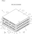
- the first heat exchange unit 10 includes a plate-fin type first heat exchanger 3.
- the plate-fin type first heat exchanger 3 is a heat exchanger having a multilayer structure including a plurality of layers of planar (layered) first flow path parts 11a, and a plurality of layer sets of second flow path parts 11b and third flow path parts 11c, which are stacked on each other.
- the first heat exchanger 3 has a planar (flat pale) structure that includes fins 12, which form individual flow paths (channels), and sidebars 13 that form outer walls of the fins 12. Also, intermediate bars 14 are arranged at midpoint positions between the sidebars 13 of each layer in which the second flow path parts 11b and the third flow path parts 11c are arranged.
- the fins 12 can have various types of shapes, the fins 12 are illustratively shown as wave-shaped corrugated fins in FIG. 2 .
- No intermediate bar 14 is arranged in the layers in which the first flow path parts 11a are arranged.
- the sidebars 13 in the layers in which the first flow path parts 11a are arranged are arranged to close outer peripheries of the first flow path parts 11a except for inlets and outlets of the first flow path parts 11a.
- the first flow path parts 11a are partitioned by plates 15, which are partition walls on both sides in a direction A. That is, the first flow path parts 11a are space parts defined by the fins 12, the sidebars 13, and the plates 15.
- headers or the like are attached to the inlets and outlets of the first flow path parts 11a so that the fluid flows into/out of the first flow path parts 11a through the headers.
- the header attached to one side of the first flow path parts 11a is connected to a high-temperature side inlet 3a (see FIG. 4 ), which will be described later. Also, the header attached to another side of the first flow path parts 11a is connected to a high-temperature side outlet 3b (see FIG. 4 ), which will be described later.
- the plates 15 and the fins 12 serve as heat transfer surfaces to transfer heat in the first heat exchanger 3.
- the direction A is a direction in which the first flow path parts 11a, sets of the second flow path parts 11b and the third flow path parts 11c are stacked on each other.
- Directions perpendicular to the direction A refer to directions B
- two directions perpendicular to each other in the directions B refer to a direction B1 and a direction B2.
- the sidebars 13 and the intermediate bars 14 are arranged to close outer peripheries of the second flow path parts 11b except for inlets and outlets of the second flow path parts 11b.
- the second flow path parts 11b are partitioned by the plates 15, which are partition walls on both sides in the direction A. That is, the second flow path parts 11b are defined by the fins 12, the sidebars 13, the intermediate bars 14, and the plates 15.
- headers or the like are attached to the inlets and outlets of the second flow path parts 11b so that the fluid flows into/out of the second flow path parts 11b through the headers.
- the header attached to one side of the second flow path parts 11b is connected to a first low-temperature side inlet 3c (see FIG. 4 ), which will be described later.
- the header attached to another side of the second flow path parts 11b is connected to a first low-temperature side outlet 3d (see FIG. 4 ), which will be described later.
- the third flow path parts 11c have a configuration similar to the second flow path parts 11b. That is, the third flow path parts 11c are defined by the fins 12, the sidebars 13, the intermediate bars 14, and the plates 15. Also, headers or the like (not shown) are attached to the inlets and outlets of the third flow path parts 11c so that the fluid flows into/out of the third flow path parts 11c through the headers.
- the header attached to one side of the third flow path parts 11c is connected to a second low-temperature side inlet 3e (see FIG. 4 ), which will be described later.
- the header attached to another side of the third flow path parts 11c is connected to a second low-temperature side outlet 3f (see FIG. 4 ), which will be described later.
- each first flow path part 11a is formed in a rectangular shape as viewed in a plan view.
- each second flow path part 11b is formed in a rectangular shape as viewed in the plan view.
- each third flow path part 11c is formed in a rectangular shape as viewed in the plan view.
- a sum of lengths of the second flow path parts 11b and lengths of the third flow path parts 11c in the direction B2 is equal to the length of each first flow path part 11a in the direction B1.
- the first heat exchanger 3 is formed in a rectangular box shape (rectangular parallelepiped shape) as a whole.
- the plurality of first flow path parts 11a are connected to the high-temperature flow paths 2 (see FIG. 1 ) to flow the high-temperature fluid 81 (see FIG. 1 ) through the first flow path parts.
- the plurality of second flow path parts 11b are connected to the second low-temperature flow path part 1b (see FIG. 1 ) and the third low-temperature flow path part 1c to flow the low-temperature fluid 80 (see FIG. 1 ) through the second flow path parts.
- the plurality of third flow path parts 11c are connected to the fourth low-temperature flow path part 1d (see FIG.
- the first heat exchanger 3 transfers heat between the high-temperature fluid 81 that flows through the first flow path parts 11a, the low-temperature fluid 80 that flows through the second flow path parts 11b, and the low-temperature fluid 80 that flows through the third flow path parts 11c.
- FIG. 2 is a view showing an exemplary perpendicular-flow type heat exchange unit in which a flow direction of the low-temperature fluid 80 (see FIG. 1 ) and a flow direction of high-temperature fluid 81 (see FIG. 1 ) are perpendicular to each other in the direction B.
- the first heat exchange unit 10 may be a parallel-flow type heat exchange unit in which the flow direction of low-temperature fluid 80 and the flow direction of high-temperature fluid 81 are the same direction, or a counter-flow type heat exchange unit in which the flow direction of low-temperature fluid 80 and the flow direction of high-temperature fluid 81 are directions opposite to each other.
- the second heat exchange unit 20 includes a plate-fin type second heat exchanger 4.
- the plate-fin type second heat exchanger 4 is a heat exchanger having a multilayer structure including a plurality of layers of planar (layered) first flow path parts 21a, and a plurality of layers of second flow path parts 21b, which are stacked on each other.
- the second heat exchanger 4 has a planar (flat pale) structure that includes fins 22, which form individual flow paths (channels), and sidebars 23 that form outer walls of the fins 22.
- the fins 22 can have various types of shapes, the fins 22 are illustratively shown as wave-shaped corrugated fins in FIG. 3 .
- the sidebars 23 are arranged to close outer peripheries of the first flow path parts 21a except for inlets or outlets of the first flow path parts 21a.
- the first flow path parts 21a are partitioned by plates 24, which are partition walls on both sides in a direction A. That is, the first flow path parts 21a are space parts defined by the fins 22, the sidebars 23, and the plates 24.
- headers or the like are attached to the inlets and outlets of the first flow path parts 21a so that the fluid flows into/out of the first flow path parts 21a through the headers.
- the sidebars 23 are arranged to close outer peripheries of the second flow path parts 21b except for inlets or outlets of the second flow path parts 21b.
- the second flow path parts 21b are partitioned by the plates 24, which are partition walls on both sides in the direction A. That is, the second flow path parts 21b are space parts defined by the fins 22, the sidebars 23, and the plates 24.
- headers or the like are attached to the inlets and outlets of the second flow path parts 21b so that the fluid flows into/out of the second flow path parts 21b through the headers.
- the plates 24 and the fins 22 serve as heat transfer surfaces to transfer heat in the second heat exchanger 4.
- each first flow path part 21a is formed in a rectangular shape as viewed in a plan view.
- each second flow path part 21b is formed in a rectangular shape as viewed in the plan view. Accordingly, the second heat exchanger 4 is formed in a rectangular box shape (rectangular parallelepiped shape) as a whole.
- the plurality of first flow path parts 21a are connected to the first low-temperature flow path part 1a (see FIG. 1 ) and the second low-temperature flow path part 1b to flow the low-temperature fluid 80 (see FIG. 1 ) through the first flow path parts. Also, the plurality of second flow path parts 21b are connected to the third low-temperature flow path part 1c (see FIG. 1 ) and the fourth low-temperature flow path part 1d to flow the low-temperature fluid 80 whose temperature is different from the low-temperature fluid that flows through the first flow path parts 21a.
- the second heat exchanger 4 transfers heat between the low-temperature fluid 80 that flows through the first flow path parts 21a, and the low-temperature fluid 80 that flows through the second flow path parts 21b.
- the second heat exchange unit 20 may be a parallel-flow type heat exchange unit in which the extension direction of the first flow path parts 21a and the extension direction of the second flow path parts 21b are the same direction, or a counter-flow type heat exchange unit in which the extension direction of the first flow path parts 21a and the extension direction of the second flow path parts 21b are directions opposite to each other.
- the low-temperature fluid tank 5 stores the low-temperature fluid 80 (see FIG. 1 ), which is liquid hydrogen. Temperature of the liquid hydrogen is substantially - 250 °C. Contrary to this, the temperature of the high-temperature fluid 81 (see FIG. 1 ) stored in the high-temperature fluid tank 30 (see FIG. 1 ) is, for example, a temperature in a range from 50°C to 60°C. Accordingly, if the heat exchange system 100 does not have the heater (first heat exchanger 3), when heat is transferred between the low-temperature fluid 80 that flows from the low-temperature fluid tank 5 and the high-temperature fluid 81 that flows from the high-temperature fluid tank 30, the high-temperature fluid 81 may freeze.
- the heat exchange system is configured to transfer heat between flows of the low-temperature fluid 80 in the second heat exchanger 4 prior to transferring heat between the low-temperature fluid 80 (see FIG. 1 ) and the high-temperature fluid 81 (see FIG. 1 ) in the first heat exchanger 3 (see FIG. 1 ).
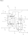
- the second heat exchanger 4 includes a first inlet 4a configured for the low-temperature fluid 80 (see FIG. 1 ) to flow into, a first outlet 4b which communicates with the first inlet 4a and is configured for the low-temperature fluid 80 that flows into through the first inlet 4a to flow out after heat transferring, a second inlet 4c configured for the low-temperature fluid 80 that flows out through the first outlet 4b and then flows through the first heat exchange unit 10 (second flow path parts 11b) to flow into, and a second outlet 4d which communicates with the second inlet 4c and is configured for the low-temperature fluid 80 that flows through the second inlet 4c into to flow out after heat transferring.
- a first inlet 4a configured for the low-temperature fluid 80 (see FIG. 1 ) to flow into
- a first outlet 4b which communicates with the first inlet 4a and is configured for the low-temperature fluid 80 that flows into through the first inlet 4a to flow out after heat transferring
- the second heat exchanger 4 is configured to transfer heat between the low-temperature fluid 80 that flows into the second heat exchanger through the first inlet 4a and the low-temperature fluid 80 that flows into the second heat exchanger through the second inlet 4c.
- the first inlet 4a and the first outlet 4b are connected to each other by the first flow path parts 21a.
- the second inlet 4c and the second outlet 4d are connected by the second flow path parts 21b.
- a dashed-line circle is attached to the first inlet 4a.
- a solid-line circle is attached to the first outlet 4b.
- a solid-line triangle is attached to the second inlet 4c.
- a solid-line square is attached to the second outlet 4d.
- the first heat exchanger 3 includes a high-temperature side inlet 3a through which the high-temperature fluid 81 (see FIG. 1 ) flows into the first heat exchanger, and a high-temperature side outlet 3b which communicates with the high-temperature side inlet 3a.
- the high-temperature side inlet 3a and the high-temperature side outlet 3b are connected by the first flow path parts 11a.
- the high-temperature fluid 81 that flows from the high-temperature fluid tank 30 (see FIG. 1 ) into the first heat exchanger 3 flows into the first heat exchanger 3 through the high-temperature side inlet 3a.
- the high-temperature fluid 81 that flows into the first heat exchanger 3 flows out of the first heat exchanger 3 through the high-temperature side outlet 3b.
- double solid-line circles are attached to the high-temperature side inlet 3a and the high-temperature side outlet 3b for convenience.
- the first heat exchanger 3 includes the first low-temperature side inlet 3c which communicates with the first outlet 4b of the second heat exchanger 4 and is configured for the low-temperature fluid 80 to flow into, and the first low-temperature side outlet 3d which communicates with the first low-temperature side inlet 3c.
- the first low-temperature side inlet 3c and the first low-temperature side outlet 3d are connected to each other by the second flow path parts 11b.
- the first heat exchanger 3 includes the second low-temperature side inlet 3e, which communicates with the second outlet 4d of the second heat exchanger 4, and the second low-temperature side outlet 3f, which communicates with the second low-temperature side inlet 3e. That is, the first heat exchanger 3 (heater) is provided between the first outlet 4b and the second inlet 4c.
- the second low-temperature side inlet 3e and the second low-temperature side outlet 3f are connected to each other by the third flow path parts 11c.
- the first low-temperature side inlet 3c, the first low-temperature side outlet 3d, the second low-temperature side inlet 3e, and the second low-temperature side outlet 3f, which are included in the first heat exchanger 3, are attached with the symbols corresponding to the inlets and the outlets to which they are connected in the inlets and the outlets of the second heat exchanger 4.
- the first inlet 4a of the second heat exchanger 4 which is indicated by the dashed-line circle, is connected to the low-temperature fluid tank 5 (see FIG. 1 ) by the low-temperature flow path 1. Specifically, the first inlet 4a is connected to the low-temperature fluid tank 5 by the first low-temperature flow path part 1a.
- the first outlet 4b of the second heat exchanger 4 communicates with the first low-temperature side inlet 3c of the first heat exchanger 3. Specifically, the first outlet 4b communicates with the first low-temperature side inlet 3c through the second low-temperature flow path part 1b. Accordingly, the low-temperature fluid 80 that flows out through the first outlet 4b flows through the first low-temperature side inlet 3c into the first heat exchanger 3.
- the solid-line circles are attached to the first outlet 4b and the first low-temperature side inlet 3c.
- the first low-temperature side outlet 3d of the first heat exchanger 3 communicates with the second inlet 4c of the second heat exchanger 4.
- the first low-temperature side outlet 3d communicates with the second inlet 4c through the third low-temperature flow path part 1c.
- the low-temperature fluid 80 that flows out through the first low-temperature side outlet 3d flows through the third low-temperature flow path part 1c, and flows back into the second heat exchanger 4 through the second inlet 4c.
- the solid-line triangles are attached to the first low-temperature side outlet 3d and the second inlet 4c.
- the second outlet 4d of the second heat exchanger 4 communicates with the second low-temperature side inlet 3e of the first heat exchanger 3. Specifically, the second outlet 4d communicates with the second low-temperature side inlet 3e through the fourth low-temperature flow path part 1d. Accordingly, the low-temperature fluid 80 that flows out through the second outlet 4d of the second heat exchanger 4 flows through the second low-temperature side inlet 3e of the first heat exchanger 3 into the first heat exchanger 3.
- solid-line squares are attached to the second outlet 4d and the second low-temperature side inlet 3e.
- the second low-temperature side outlet 3f which is indicated by a single-pointed line circle, is connected to the low-temperature fluid reservoir 7 (see FIG. 1 ) by the low-temperature flow path 1. Specifically, the second low-temperature side outlet 3f is connected to the low-temperature fluid reservoir 7 by the fifth low-temperature flow path part 1e.
- the low-temperature fluid 80 (see FIG. 1 ) stored in low-temperature fluid tank 5 (see FIG. 1 ) flows through the first low-temperature flow path part 1a, the first flow path parts 21a, the second low-temperature flow path part 1b, the second flow path parts 11b, the third low-temperature flow path part 1c, the second flow path parts 21b, the fourth low-temperature flow path part 1d, the third flow path parts 11c and the fifth low-temperature flow path part 1e in this order into the low-temperature fluid reservoir 7.
- the high-temperature fluid tank 30 (see FIG. 1 ) is connected to the first heat exchanger 3 by the high-temperature flow path 2. Specifically, the high-temperature fluid tank 30 is connected to the first heat exchanger 3 by the first high-temperature flow path part 2a.
- the high-temperature side outlet 3b of the first heat exchanger 3 is connected to the second high-temperature flow path part 2b. Accordingly, the high-temperature fluid 81 (see FIG. 1 ) that flows from the high-temperature fluid tank 30 through the first high-temperature flow path part 2a flows through the high-temperature side inlet 3a into the first flow path parts 11a, and flows out through the high-temperature side outlet 3b, and flows through the second high-temperature flow path part 2b.
- the low-temperature fluid 80 (see FIG. 1 ) that flows into the low-temperature flow path 1 from the low-temperature fluid tank 5 ( FIG. 1 ) transfers heat in an order of circled numbers 1 to 3 indicated in FIG. 4 .
- the first (circled number 1) heat transferring is executed in the second heat exchanger 4.
- the low-temperature fluid 80 that flows from the low-temperature fluid tank 5 ( FIG. 1 ) into the second heat exchanger 4 (see FIG. 1 ) transfers heat from the low-temperature fluid 80 that flows out of the first heat exchanger 3. That is, the first heat transferring is executed between the low-temperature fluid 80 that flows into the first flow path parts 21a and the low-temperature fluid 80 that flows into the second flow path parts 21b.
- the first heat transferring is executed between the low-temperature fluid 80 that flows from the low-temperature fluid tank 5 and the low-temperature fluid 80 that flows out of the second heat exchanger 4 and is circulated by itself to flow into the second heat exchanger 4 again.
- the low-temperature fluid 80 that flows out of the first heat exchanger 3 transfers heat from the high-temperature fluid 81 (see FIG. 1 ) in the first heat exchanger 3. Accordingly, the low-temperature fluid 80 that flows out through the first outlet 4b is higher in temperature than the low-temperature fluid 80 that flows in through the first inlet 4a.
- a heat capacity of the second heat exchanger 4 heats the low-temperature fluid 80 that flows into the first flow path parts 21a in the activation of the heat exchange system 100.
- a flow rate of the low-temperature fluid 80 that flows into the second heat exchanger 4 is reduced to reduce a thermal stress that occurs in the second heat exchanger 4. That is, the heat exchange system 100 is driven in a preparation mode of flowing a small amount of low-temperature fluid 80 so as to heat the low-temperature fluid 80 by using the heat capacity of the second heat exchanger 4 in the activation of the heat exchange system 100.
- the low-temperature fluid 80 transfers heat as the second (circled 2) heat transferring.
- the second heat exchange is executed in the first heat exchanger 3. Specifically, the second heat transferring is executed between the high-temperature fluid 81 (see FIG. 1 ) that flows into the first flow path parts 11a and the low-temperature fluid 80 that flows into the second flow path parts 11b.
- the low-temperature fluid 80 whose heat is transferred by the second heat exchanger 4 and which flows out through the first outlet 4b flows into the first heat exchanger 3 and transfers heat from the high-temperature fluid 81.
- the first heat exchanger 3 (heater) is configured to heat the low-temperature fluid 80 that has flowed out through the first outlet 4b before flowing in through the second inlet 4c.
- the low-temperature fluid 80 that flows back to the second heat exchanger 4 through the second inlet 4c as a high-temperature side fluid transfers heat to the low-temperature fluid 80 that flows in the first flow path parts 21a in the first heat transferring.
- the low-temperature fluid 80 that flows out through the second outlet 4d is higher in temperature than the low-temperature fluid 80 that flows out through the first outlet 4b.
- temperatures of flows of the low-temperature fluid 80 after heat transferring becomes temperatures near an intermediate temperature between both the flows of the low-temperature fluid.
- the low-temperature fluid 80 that flows out through the second outlet 4d may become at a temperature lower than the low-temperature fluid 80 that flows out through the first outlet 4b.
- the low-temperature fluid 80 transfers heat as the third (circled 3) heat transferring.
- the third heat transferring is executed in the first heat exchanger 3. Specifically, the third heat transferring is executed between the high-temperature fluid 81 (see FIG. 1 ) that flows into the first flow path parts 11a and the low-temperature fluid 80 that flows into the third flow path parts 11c.
- the low-temperature fluid 80 whose heat is transferred by the second heat exchanger 4 and which flows out through the second outlet 4d flows into the first heat exchanger 3 and transfers heat from the high-temperature fluid 81.
- the second heat transferring and the third heat transferring are executed in the first heat exchanger 3.
- the first heat exchanger 3 is configured to transfer heat between the high-temperature fluid 81 in the high-temperature flow path 2 and the low-temperature fluid 80 that flows in through the first low-temperature side inlet 3c of the first heat exchanger 3, and between the high-temperature fluid 81 in the high-temperature flow path 2 and the low-temperature fluid 80 that flows in through the second low-temperature side inlet 3e of the first heat exchanger 3.
- the first heat exchanger 3 is configured to transfer heat between three flows of fluids, which are a flow of the high-temperature fluid 81 that flows into the first flow path parts 11a, a flow of the low-temperature fluid 80 that flows into the second flow path parts 11b, and a flow of the low-temperature fluid 80 that flows into the third flow path parts 11c.
- the low-temperature fluid 80 that has transferred heat as the third transferring flows out through the second low-temperature side outlet 3f, flows through the fifth low-temperature flow path part 1e, and is stored in the low-temperature fluid reservoir 7.
- a graph 70 shown in FIG. 5 its horizontal axis indicates a heat amount, and its vertical axis indicates temperature.
- the solid arrows 40a to 40d in the graph 70 show changes of temperature and the heat amount of the low-temperature fluid 80 (see FIG. 1 ).
- the arrow 40a shows a change of temperature and the heat amount of the low-temperature fluid 80 that flows in through the first inlet 4a (see FIG. 4 ) and flows out through the first outlet 4b (see FIG. 4 ).
- the arrow 40b shows a change of temperature and the heat amount of the low-temperature fluid 80 that flows in through the second inlet 4c (see FIG. 4 ) and flows out through the second outlet 4d (see FIG. 4 ).
- the arrow 40c shows a change of temperature and the heat amount of the low-temperature fluid 80 that flows in through the first low-temperature side inlet 3c and flows out through the first low-temperature side outlet 3d.
- the arrow 40d shows a change of temperature and the heat amount of the low-temperature fluid 80 that flows in through the second low-temperature side inlet 3e and flows out through the second low-temperature side outlet 3f.
- single-pointed line arrows 50a and 50b in the graph 70 show changes of temperature and the heat amount of the high-temperature fluid 81 (see FIG. 1 ).
- the arrows 50a and 50b show changes of temperature and the heat amount of the high-temperature fluid 81 (see FIG. 1 ) that flows in through the high-temperature side inlet 3a (see FIG. 4 ) and flows out through the high-temperature side outlet 3b (see FIG. 4 ).
- start points of the arrows 40a to 40d, and the arrows 50a and 50b indicate temperatures and heat amounts at heat transferring starts, and their end points indicate temperatures and heat amounts at heat transferring ends.
- a region R1 in the graph 70 represents heat transferring in the second heat exchanger 4 (see FIG. 4 ), and regions R2 and R3 represent heat transferring in the first heat exchanger 3 (see FIG. 4 ).
- heat transfers of the regions R1 to R3 correspond to first to third heat transfers indicated by the circled numbers in FIG. 4 , respectively.
- heat is transferred between the low-temperature fluid 80 that flows in through the first inlet 4a (see FIG. 4 ) and flows out through the first outlet 4b (see FIG. 4 ), and the low-temperature fluid 80 that flows in through the second inlet 4c (see FIG. 4 ) and flows out through the second outlet 4d (see FIG. 4 ) in the second heat exchanger 4 (see FIG. 4 ).
- the temperature of the low-temperature fluid 80 that slows in through the first inlet 4a and flows out through the first outlet 4b increases from a temperature t1 to a temperature t2 as shown by the arrow 40a.
- the temperature of the low-temperature fluid 80 that flows in through the second inlet 4c and flows out through the second outlet 4d decreases from a temperature t3 to a temperature t4 as shown by the arrow 40b.
- the temperature of the low-temperature fluid 80 that flows in through the first low-temperature side inlet 3c and flows out through the first low-temperature side outlet 3d increases from a temperature t2 to a temperature t3.
- the temperature of the high-temperature fluid 81 that flows in through the high-temperature side inlet 3a and flows out through the high-temperature side outlet 3b decreases from a temperature T1 to a temperature T2.
- the temperature t2 at the start point of the arrow 40c is higher. That is, a temperature difference td2 between the temperature t2 at the start point of the arrow 40c and the temperature T1 at the start point of the arrow 50a becomes smaller than a temperature difference td1 between the temperature t1 at the start point of the arrow 40a and the temperature T1 at the start point of the arrow 50a. For this reason, the high-temperature fluid 81 becomes unlikely to freeze as compared with a case in which the low-temperature fluid 80 is not previously heated by the second heat exchanger 4.
- the temperature of the low-temperature fluid 80 that flows in through the second low-temperature side inlet 3e and flows out through the second low-temperature side outlet 3f increases from a temperature t4 to a temperature t5.
- the temperature of the high-temperature fluid 81 that flows in through the high-temperature side inlet 3a and flows out through the high-temperature side outlet 3b decreases from the temperature T1 to the temperature T2.
- the temperature t4 at the start point of the arrow 40d is higher. That is, a temperature difference td3 between the temperature t4 at the start point of the arrow 40d and the temperature T1 at the start point of the arrow 50b becomes smaller than the temperature difference td1 between the temperature t1 at the start point of the arrow 40a and the temperature T1 at the start point of the arrow 50b. For this reason, the high-temperature fluid 81 becomes unlikely to freeze as compared with a case in which the low-temperature fluid 80 is not previously heated by the second heat exchanger 4.
- the high-temperature flow path 2 (see FIG. 4 ) through which the high-temperature fluid 81 flow is not necessarily separately provided.
- the flow rate of the high-temperature fluid 81 that flow through the high-temperature flow path 2 can be set to a flow rate that can supply the sum of the heat amounts represented by the arrow 50a and the arrow 50b.
- the low-temperature fluid 80 (see FIG. 1 ) stored in the low-temperature fluid reservoir 7 (see FIG. 1 ) is gaseous hydrogen (hydrogen gas) at an ordinary temperature (temperature t5). Also, when the low-temperature fluid 80 is supplied to the to-be-supplied subject 90 (see FIG. 1 ), the temperature of the low-temperature fluid 80 will increase. An upper temperature limit of the low-temperature fluid 80 when supplied to the to-be-supplied subject 90 is previously defined depending on each to-be-supplied subject 90. Accordingly, the supplier 8 is configured to be able to supply the low-temperature fluid 80 at a desired temperature depending on each to-be-supplied subject 90.
- the supplier 8 is configured to supply the low-temperature fluid 80 that is adjusted to a temperature different from the temperature of the low-temperature fluid 80 stored in the low-temperature fluid reservoir 7.
- the desired temperature is a temperature t6
- the supplier 8 cools the low-temperature fluid 80 stored in the low-temperature fluid reservoir 7 at the ordinary temperature (temperature t5) to the predetermined temperature (temperature t6).
- the ordinary temperature (temperature T5) is, for example, 10°C
- the temperature t6 is, for example, - 40°C.
- the supplier 8 (see FIG. 1 ) is configured to mix the low-temperature fluid 80 (see FIG. 1 ) that flows from the low-temperature fluid reservoir 7 (see FIG. 1 ) and the low-temperature fluid 80 that flows from the branch flow path 9 (see FIG. 1 ) and is lower in temperature than the low-temperature fluid 80 that is stored in the low-temperature fluid reservoir 7.
- the supplier 8 is configured to adjust a flow rate of the low-temperature fluid 80 that flows in from the supply flow path 8a and a flow rate of the low-temperature fluid 80 that flows in from the branch flow path 9 by adjusting the first supply valve 8b (see FIG. 1 ) and the second supply valve 8c (see FIG. 1 ), and to supply the low-temperature fluid 80 at the predetermined temperature (temperature t6) .
- a heat exchange system 100 includes a first heat exchanger 3 for transferring heat between a low-temperature fluid 80 and a high-temperature fluid 81 whose temperature is higher than the low-temperature fluid 80; a second heat exchanger 4 for transferring heat between flows of the low-temperature fluid 80, the second heat exchanger 4 including a first inlet 4a through which the low-temperature fluid 80 flows into the second heat exchanger, a first outlet 4b which communicates with the first inlet 4a to form one of the flows of the low-temperature fluid and through which the low-temperature fluid 80 that flows through the first inlet 4a into the second heat exchanger flows out of the second heat exchanger after heat transferring, a second inlet 4c through which the low-temperature fluid 80 that flows out of the second heat exchanger through the first outlet 4b flows into the second heat exchanger, and a second outlet 4d which communicates with the second inlet 4c to form another of the flows of the low-temperature fluid and through which the low-temperature fluid 80 that
- the low-temperature fluid 80 is heated by the second heat exchanger 4 before the low-temperature fluid 80 flows into the first heat exchanger 3 so that the low-temperature fluid 80 that flows into the first heat exchanger 3 can be previously heated. For this reason, it is possible to reduce temperature difference between the low-temperature fluid 80 that flows into the first heat exchanger 3 and the high-temperature fluid 81 as compared with a configuration including no second heat exchanger 4. Consequently, it is possible to prevent the high-temperature fluid 81 from freezing in the first heat exchanger 3.
- the first heat exchanger 3 serves as the heater; the first heat exchanger 3 includes the first low-temperature side inlet 3c configured for the low-temperature fluid 80 to flow into, and a first low-temperature side outlet 3d which communicates with the first low-temperature side inlet 3c; the first outlet 4b of the second heat exchanger 4 communicates with the first low-temperature side inlet 3c of the first heat exchanger 3; and the low-temperature fluid 80 that flows out of the second heat exchanger through the first outlet 4b flows into the first heat exchanger 3 through the first low-temperature side inlet 3c to transfer heat from the high-temperature fluid 81 in the first heat exchanger, and flows back to the second heat exchanger 4 through the second inlet 4c after heat transferring.
- the low-temperature fluid 80 that flows out through the first outlet 4b can be heated by the first heat exchanger 3, and be returned through the second inlet 4c to the second heat exchanger 4.
- the low-temperature fluid 80 that flows out through the first outlet 4b is higher in temperature than the low-temperature fluid 80 that flows in through the first inlet 4a
- the low-temperature fluid 80 that flows out through the second outlet 4d becomes higher in temperature than the low-temperature fluid 80 that flows in through the first inlet 4a. That is, both the low-temperature fluid 80 that flows out through the first outlet 4b and flows into the first heat exchanger 3, and the low-temperature fluid 80 that flows in through the second outlet 4d and flows into the first heat exchanger 3 flow into the first heat exchanger 3 with their temperatures being higher than the low-temperature fluid 80 that flows into the first heat exchanger through the first inlet 4a.
- temperature difference between the low-temperature fluid 80 and the high-temperature fluid 81 can be reduced as compared with a configuration in which the low-temperature fluid 80 directly flows into the first heat exchanger 3 without flowing in the second heat exchanger 4. Consequently, it is possible to prevent the high-temperature fluid 81 from freezing as compared with the configuration in which the low-temperature fluid 80 directly flows into the first heat exchanger 3 without flowing in the second heat exchanger 4.
- the first heat exchanger 3 further includes the second low-temperature side inlet 3e, which communicates with the second outlet 4d of the second heat exchanger 4, and the second low-temperature side outlet 3f which communicates with the second low-temperature side inlet 3e; and the low-temperature fluid 80 that flows out of the second heat exchanger through the second outlet 4d of the second heat exchanger 4 flows into the first heat exchanger 3 through the second low-temperature side inlet 3e of the first heat exchanger 3 and transfers heat from the high-temperature fluid 81.
- the first low-temperature side outlet 3 e of the first heat exchanger 3 communicates with the second inlet 4 d of the second heat exchanger 4, it is possible to easily flow the low-temperature fluid 80 whose heat has been transferred in the second heat exchanger 4 into the first heat exchanger 3. Consequently, it is possible to easily form a fluid circuit capable of flowing the low-temperature fluid 80 into the first heat exchanger 3 with the low-temperature fluid being previously heated by the second heat exchanger 4.
- the first heat exchanger 3 is configured to transfer heat between the high-temperature fluid 81 in the high-temperature flow path 2 and the low-temperature fluid 80 flowing into the first heat exchanger through the first low-temperature side inlet 3c of the first heat exchanger 3, and to transfer heat between the high-temperature fluid 81 in the high-temperature flow path 2 and the low-temperature fluid 80 flowing into the first heat exchanger through the second low-temperature side inlet 3e of the first heat exchanger 3.
- the first heat exchanger 3 can transfer heat between three flows of the high-temperature fluid 81, the low-temperature fluid 80 that flows in through the first low-temperature side inlet 3c, and the low-temperature fluid 80 that flows in through the second low-temperature side inlet 3e. Consequently, it is possible to prevent increase of the number of parts and a complicated structure as compared with a configuration which separately includes a heat exchanger that transfers heat between the high-temperature fluid 81 and the low-temperature fluid 80 that flows in through the first low-temperature side inlet 3c, and a heat exchanger that transfers heat between the high-temperature fluid 81 and the low-temperature fluid 80 that flows in through the second low-temperature side inlet 3e.
- first heat exchanger 3 and the second heat exchanger 4 are provided in the first heat exchange unit 10 and the second heat exchange unit 20 which are different from each other, respectively. Accordingly, a fluid circuit capable of previously heating the low-temperature fluid 80 that flows into the first heat exchanger 3 to increase temperature the low-temperature fluid by using the second heat exchanger 4 can be easily formed by connecting the first heat exchange unit 10 including the first heat exchanger 3 and the second heat exchange unit 20 including the second heat exchanger 4 to each other. Consequently, it is possible to prevent installation of pipes of the heat exchangers from becoming complicated as compared with a heat exchange unit including both the first heat exchanger 3 and the second heat exchanger 4, for example.
- the low-temperature fluid tank 5 for storing the liquid low-temperature fluid 80; the low-temperature fluid reservoir 7 for reserving the low-temperature fluid 80 that is heated and is vaporized by the first heat exchanger 3; the low-temperature fluid pump 6 for flowing the low-temperature fluid 80 stored in the low-temperature fluid tank 5 through the low-temperature flow path 1; the supplier 8 connected to the low-temperature fluid reservoir 7 to supply the vaporized low-temperature fluid 80 to the to-be-supplied subject 90; and the branch flow path 9 branched from the low-temperature flow path 1 and connected to the supplier 8 to flow the low-temperature fluid 80 through the branch flow path are provided, and the supplier 8 is configured to mix the low-temperature fluid 80 flowing in from the low-temperature fluid reservoir 7 and the low-temperature fluid 80 flowing in from the branch flow path 9 and is lower in temperature than the low-temperature fluid 80 that is stored in the low-temperature fluid reservoir 7.
- the temperature of the low-temperature fluid 80 can be easily reduced by mixing the low-temperature fluid 80 that is stored in the low-temperature fluid reservoir 7 with the low-temperature fluid 80 that flows from the branch flow path 9. Accordingly, the temperature of the low-temperature fluid 80 that is stored in the reservoir can be reduced to a temperature when supplied to the supplied subject without using a refrigerator, or the like. Consequently, it is possible to prevent the system from becoming large as compared to a configuration including such a refrigerator for reducing the temperature of the low-temperature fluid 80 that is stored in the low-temperature fluid reservoir 7, for example.
- the low-temperature fluid 80 is liquid hydrogen
- the high-temperature fluid 81 is warm water. Accordingly, it is possible to provide a heat exchange system capable 100 of preventing, when transferring heat between liquid hydrogen as the low-temperature fluid 80 and warm water as the high-temperature fluid 81, the warm water from freezing.
- first heat exchanger 3 is provided in the first heat exchange unit 10
- second heat exchanger 4 is provided in the second heat exchange unit 20
- the present invention is not limited to this.
- the first heat exchanger 3 and the second heat exchanger 4 may be provided in a single heat exchange unit 210 as in a heat exchange system 200 according to a modified embodiment shown in FIG. 6 .
- the heat exchange system 100 increases a pressure of the low-temperature fluid 80 stored in the low-temperature fluid tank 5 to a predetermined pressure by using the low-temperature fluid pump 6, and vaporizes the low-temperature fluid in the first heat exchanger 3 and the second heat exchanger 4 has been shown in the aforementioned embodiment, the present invention is not limited to this.
- the heat exchange system may be configured to increase the pressure of the low-temperature fluid 80 that is vaporized by the first heat exchanger 3 and the second heat exchanger 4 to a predetermined pressure and to store the low-temperature fluid with the increased pressure in the low-temperature fluid reservoir 7.
- the present invention is not limited to this.
- the low-temperature fluid 80 that flows out through the first outlet 4b and flows in through the second inlet 4c may not be heated by the first heat exchanger 3 (heater).
- a heating device such as a heater may be provided at a position on the low-temperature flow path 1 between the first outlet 4b and the second inlet 4c, and be configured to heat the low-temperature fluid 80.
- the low-temperature fluid 80 that flows in through the second inlet 4c may be heated to a predetermined temperature by transferring heat between the low-temperature fluid 80 and air after the low-temperature fluid flows out through the first outlet 4b until the low-temperature fluid flows in through the second inlet 4c.
- the first outlet 4b and the second inlet 4c may be connected to each other by the low-temperature flow path 1 that has a length (flow path length) that can heat the low-temperature fluid 80 by air to the predetermined temperature.
- the heating device such as a heater is provided between the first outlet 4b and the second inlet 4c, the system becomes large.
- the first heat exchanger 3 is preferably configured to serve as the heater.
- the present invention is not limited to this. If the temperature of the low-temperature fluid 80 that flows out through the second outlet 4d is higher than the temperature of the low-temperature fluid 80 that flows in through the first inlet 4a, it may be higher or lower than the temperature of the low-temperature fluid 80 that flows out through the first outlet 4b.
- the present invention is not limited to this.
- the first heat exchanger 3 may include neither the second low-temperature side inlet 3e nor the second low-temperature side outlet 3f.
- the first heat exchanger 3 may not configured to transfer both heat between the high-temperature fluid 81 and the low-temperature fluid 80 that flows in through the first low-temperature side inlet 3c, and heat between the high-temperature fluid 81 and the low-temperature fluid 80 that flows in through the second low-temperature side inlet 3e.
- a heat exchange unit for transferring heat between the low-temperature fluid 80 that flows out through the second outlet 4d and the high-temperature fluid 81 may be separately provided.
- the first heat exchanger 3 includes neither the second low-temperature side inlet 3e nor the second low-temperature side outlet 3f
- a heat exchange unit for transferring heat between the low-temperature fluid 80 that flows out through the second outlet 4d and the high-temperature fluid 81 is separately provided, and as a result the system becomes large.
- the first heat exchanger 3 preferably includes the second low-temperature side inlet 3e and the second low-temperature side outlet 3f.
- the heat exchange system 100 may include no low-temperature fluid reservoir 7 if the heat exchange system 100 includes the low-temperature fluid pump 6 capable of supplying the to-be-supplied subject 90 with a predetermined supply amount of the low-temperature fluid 80.
- the low-temperature fluid 80 is liquid hydrogen, and the high-temperature fluid 81 is warm water has been shown in the aforementioned embodiment, the present invention is not limited to this.
- the low-temperature fluid 80 may be liquid helium or liquefied natural gas.
- the high-temperature fluid 81 may be ethylene glycol.
- first heat exchanger 3 and the second heat exchanger 4 are plate-fin type heat exchangers
- the present invention is not limited to this.
- the first heat exchanger 3 and the second heat exchanger 4 may be any type of heat exchangers.
- the first heat exchanger 3 and the second heat exchanger 4 may be diffusion-bonded type heat exchangers in which a plurality of heat transfer plates having grooved flow paths formed thereon are bonded by diffusion phenomenon, for example.
- the branch flow path 9 may branch from any point on the low-temperature flow path 1 as long as temperature of the low-temperature fluid 80 that is branched to the branch flow path is lower than the low-temperature fluid 80 that is stored in the low-temperature fluid reservoir 7.
- the branch flow path 9 may branch from any point on the low-temperature flow path 1 except the fifth low-temperature flow path part 1e.
Landscapes
- Engineering & Computer Science (AREA)
- Mechanical Engineering (AREA)
- General Engineering & Computer Science (AREA)
- Physics & Mathematics (AREA)
- Thermal Sciences (AREA)
- Heat-Exchange Devices With Radiators And Conduit Assemblies (AREA)
- Filling Or Discharging Of Gas Storage Vessels (AREA)
Abstract
Description
- The present invention relates to a heat exchange system, in particular to a heat exchange system for transferring heat between a low-temperature fluid and a high-temperature fluid.
- Heat exchange systems for transferring heat between a low-temperature fluid and a high-temperature fluid are known in the art. Such a heat exchange system is disclosed in Japanese Patent Laid-Open Publication No.
JP 2010-101617 - The above Japanese Patent Laid-Open Publication No.
JP 2010-101617 JP 2010-101617 JP 2010-101617 - Patent Document 1: Japanese Patent Laid-Open Publication No.
JP 2010-101617 - Here, in the exchange device (heat exchange system) disclosed in the above Japanese Patent Laid-Open Publication No.
JP 2010-101617 - The present invention is intended to solve the above problem, and one object of the present invention is to provide a heat exchange system capable of preventing, when transferring heat between a low-temperature fluid and a liquid high-temperature fluid, the high-temperature fluid from freezing.
- In order to attain the aforementioned object, a heat exchange system according to the present invention includes a first heat exchanger for transferring heat between a low-temperature fluid and a high-temperature fluid whose temperature is higher than the low-temperature fluid; a second heat exchanger for transferring heat between flows of the low-temperature fluid; and a heater, the second heat exchanger including a first inlet configured for the low-temperature fluid to flow into, a first outlet which communicates with the first inlet, a second inlet configured for the low-temperature fluid to flow into, and a second outlet which communicates with the second inlet, wherein the second heat exchanger is configured to transfer heat between the low-temperature fluid flowing in from the first inlet and the low-temperature fluid flowing out from the first outlet and flowing in from the second inlet, the heater is provided between the first outlet and the second inlet and is configured to heat the low-temperature fluid flowing out from the first outlet, the low-temperature fluid flowing out from the second outlet can flow into the first exchanger.
- As discussed above, the heat exchange system according to the present invention includes a first heat exchanger for transferring heat between a low-temperature fluid and a high-temperature fluid; a second heat exchanger for transferring heat between flows of the low-temperature fluid; and a heater configured to heat the low-temperature fluid flowing out from the first outlet, the low-temperature fluid flowing out from the second outlet can flow into the first exchanger. Accordingly, since the low-temperature fluid is heated by the second heat exchanger before the low-temperature fluid flows into the first heat exchanger, the low-temperature fluid that flows into the first heat exchanger can be previously heated. For this reason, it is possible to reduce temperature difference between the low-temperature fluid that flows into the first heat exchanger and the liquid high-temperature fluid as compared with a configuration including no second heat exchanger. Consequently, it is possible to prevent, when transferring heat between the low-temperature fluid and the liquid high-temperature fluid, the high-temperature fluid from freezing.
- In the aforementioned heat exchange system, it is preferable that the first heat exchanger serves as the heater; that the first heat exchanger including a first low-temperature side inlet configured for the low-temperature fluid to flow into; and, and a first low-temperature side outlet which communicates with the first low-temperature side inlet; that the first outlet of the second heat exchanger communicates with the first low-temperature side inlet of the first heat exchanger, that the low-temperature fluid flowing out from the first outlet can flow into the first low-temperature side inlet, flow out from the first low-temperature side outlet, and flow into the second inlet. According to this configuration, the low-temperature fluid that flows out through the first outlet can be heated by the first heat exchanger, and be returned through the second inlet to the second heat exchanger. As a result, it is possible to heat the low-temperature fluid that flows in through the second inlet without providing a heater for heating the low-temperature fluid that flows out through the first outlet. Consequently, it is possible to reduce increase of size of the heat exchange system as compared with a configuration including the heater or the like for heating the low-temperature fluid that flows out through the first outlet.
- In this configuration, since the low-temperature fluid that flows out through the first outlet is higher in temperature than the low-temperature fluid that flows in through the first inlet, the low-temperature fluid that flows out through the second outlet becomes higher in temperature than the low-temperature fluid that flows in through the first inlet. That is, both the low-temperature fluid that flows out through the first outlet and flows into the first heat exchanger, and the low-temperature fluid that flows in through the second outlet and flows into the first heat exchanger flow into the first heat exchanger with their temperatures being higher than the low-temperature fluid that flows in through the first inlet. Accordingly, temperature difference between the low-temperature fluid and the high-temperature fluid can be reduced as compared with a configuration in which the low-temperature fluid directly flows into the first heat exchanger without flowing in the second heat exchanger. Consequently, it is possible to prevent the high-temperature fluid from freezing as compared with the configuration in which the low-temperature fluid directly flows into the first heat exchanger without flowing in the second heat exchanger.
- In the configuration in which the low-temperature fluid can flow the second inlet, it is preferable that the first heat exchanger further includes a second low-temperature side inlet which communicates with the second outlet, and a second low-temperature side outlet which communicates with the second low-temperature side inlet; and that the low-temperature fluid flowing out from the second outlet can flow into the second low-temperature side inlet. According to this configuration, since the first low-temperature side outlet of the first heat exchanger communicates with the second inlet of the second heat exchanger, it is possible to easily flow the low-temperature fluid whose heat has been transferred in the second heat exchanger into the first heat exchanger. Consequently, it is possible to easily form a fluid circuit capable of flowing the low-temperature fluid into the first heat exchanger with the low-temperature fluid being previously heated by the second heat exchanger.
- In this configuration, it is preferable that the first heat exchanger is configured to transfer heat between the high-temperature fluid and the low-temperature fluid flowing into the first heat exchanger through the first low-temperature side inlet, and to transfer heat between the high-temperature fluid and the low-temperature fluid flowing into the first heat exchanger through the second low-temperature side inlet. According to this configuration, the first heat exchanger can transfer heat between three flows of the high-temperature fluid, the low-temperature fluid that flows in through the first low-temperature side inlet, and the low-temperature fluid that flows in through the second low-temperature side inlet. Consequently, it is possible to prevent increase of the number of parts and a complicated structure as compared with a configuration which separately includes a heat exchanger that transfers heat between the high-temperature fluid and the low-temperature fluid that flows in through the first low-temperature side inlet, and a heat exchanger that transfers heat between the high-temperature fluid and the low-temperature fluid that flows in through the second low-temperature side inlet.
- In the configuration in which the low-temperature fluid that flows out through the first outlet and the low-temperature fluid that flows out through second outlet are higher in temperature than the low-temperature fluid that flows in through the first inlet, it is preferable that a first heat exchange unit; and a second heat exchange unit are further provided, the first heat exchanger is provided in the first heat unit or the second heat unit, the second heat exchanger is provided in the other side. According to this configuration, a fluid circuit capable of previously heating the low-temperature fluid that flows into the first heat exchanger to increase temperature the low-temperature fluid by using the second heat exchanger can be easily formed by connecting the first heat exchange unit including the first heat exchanger and the second heat exchange unit including the second heat exchanger to each other. Consequently, it is possible to prevent installation of pipes of the heat exchangers from becoming complicated as compared with a single heat exchange unit including both the first heat exchanger and the second heat exchanger, for example.
- In the configuration in which the low-temperature fluid that flows out through the first outlet and the low-temperature fluid that flows out through second outlet are higher in temperature than the low-temperature fluid that flows in through the first inlet, it is preferable that a low-temperature fluid tank for storing the liquid low-temperature fluid; a low-temperature flow path; a low-temperature fluid pump for flowing the low-temperature fluid stored in the low-temperature fluid tank through the low-temperature flow path; a low-temperature fluid reservoir for reserving the low-temperature fluid flowing out from the first heat exchanger; a supplier for supplying the low-temperature fluid flowing out from the low-temperature fluid reservoir to outside; and a branch flow path branched from the low-temperature flow path and connected to the supplier are further provided, and that the supplier is configured to mix the low-temperature fluid flowing in from the low-temperature fluid reservoir and the low-temperature fluid flowing in from the branch flow path and is lower in temperature than the low-temperature fluid that is stored in the low-temperature fluid reservoir. According to this configuration, in a case in which the low-temperature fluid which is stored in the low-temperature fluid reservoir and whose temperature is reduced is supplied to the to-be-supplied subject, the temperature of the low-temperature fluid can be easily reduced by mixing the low-temperature fluid that is stored in the low-temperature fluid reservoir with the low-temperature fluid that flows from the branch flow path. Accordingly, the temperature of the low-temperature fluid that is stored in the reservoir can be reduced to a temperature when supplied to the supplied subject without using a refrigerator, or the like. Consequently, it is possible to prevent the system from becoming large as compared to a configuration including such a refrigerator for reducing the temperature of the low-temperature fluid that is stored in the low-temperature fluid reservoir, for example.
- In the aforementioned heat exchange system, it is preferable that the low-temperature fluid is liquid hydrogen; and that high-temperature fluid is warm water. According to this configuration, it is possible to provide a heat exchange system capable of preventing, when transferring heat between liquid hydrogen as the low-temperature fluid and warm water as the high-temperature fluid, the warm water from freezing.
- According to the present invention, as discussed above, it is possible to provide a heat exchange system capable of preventing a high-temperature fluid from freezing when transferring heat between a low-temperature fluid and the high-temperature fluid.
-
-
FIG. 1 is a schismatic diagram illustrating an entire configuration of a heat exchange system according to an embodiment. -
FIG. 2 is a schismatic perspective view illustrating a configuration of a first heat exchange unit including a first heat exchanger according to the embodiment. -
FIG. 3 is a schismatic perspective view illustrating a configuration of a second heat exchange unit including a second heat exchanger according to the embodiment. -
FIG. 4 is a schismatic diagram illustrating a configuration of connection between the first heat exchanger and the second heat exchanger, and flow paths of a low-temperature fluid and a high-temperature fluid according to the embodiment. -
FIG. 5 is a schismatic diagram illustrating heat exchange between flows of a first fluid, and exchange between flows of the first fluid and a second fluid in the heat exchange system according to the embodiment. -
FIG. 6 is a schismatic diagram illustrating an entire configuration of a heat exchange system according to one modified embodiment. - Embodiments according to the present invention will be described with reference to the drawings.
- The following description describes a
heat exchange system 100 according to one embodiment with reference toFIGS. 1 to 5 . - As shown in
FIG. 1 , theheat exchange system 100 includes a low-temperature flow path 1, a high-temperature flow path 2, and afirst heat exchanger 3, asecond heat exchanger 4, a heater, a low-temperature fluid tank 5, a low-temperature fluid pump 6, a low-temperature fluid reservoir 7, asupplier 8, abranch flow path 9, and a high-temperature fluid tank 30. - The low-temperature flow path 1 is a flow path through which a low-
temperature fluid 80 being lower temperature. The low-temperature flow path 1 has one end connected to the low-temperature fluid pump 6, and another end connected to the low-temperature fluid reservoir 7. The low-temperature flow path 1 is, for example, one or more pipes. Here, the low-temperature fluid 80 is, for example, liquid hydrogen, liquid helium, liquefied natural gas, or the like. In this embodiment, the low-temperature fluid 80 is liquid hydrogen. - In this embodiment, the low-temperature flow path 1 includes a first low-temperature
flow path part 1a, a second low-temperatureflow path part 1b, a third low-temperatureflow path part 1c, a fourth low-temperatureflow path part 1d and the fifth low-temperatureflow path part 1e. - The first low-temperature
flow path part 1a is configured to connect the low-temperature fluid pump 6 to thesecond heat exchanger 4. Also, the second low-temperatureflow path part 1b is configured to connect thesecond heat exchanger 4 to thefirst heat exchanger 3. Also, the third low-temperatureflow path part 1c is configured to connect thefirst heat exchanger 3 to thesecond heat exchanger 4. Also, the fourth low-temperatureflow path part 1d is configured to connect thesecond heat exchanger 4 to thefirst heat exchanger 3. Also, the fifth low-temperatureflow path part 1e is configured to connect thefirst heat exchanger 3 to the low-temperature fluid reservoir 7. - Accordingly, the low-
temperature fluid 80 stored in the low-temperature fluid tank 5 is flowed through first low-temperatureflow path part 1a, thesecond heat exchanger 4, the second low-temperatureflow path part 1b, thefirst heat exchanger 3, the third low-temperatureflow path part 1c, thesecond heat exchanger 4, the fourth low-temperatureflow path part 1d, thefirst heat exchanger 3 and the fifth low-temperatureflow path part 1e in this order by the low-temperature fluid pump 6, and is stored in the low-temperature fluid reservoir 7. In this embodiment, theheat exchange system 100 is a system for storing the low-temperature fluid 80b (hydrogen gas) that is vaporized from the liquid low-temperature fluid 80a that is liquid hydrogen by transferring heat by using thefirst heat exchanger 3 and thesecond heat exchanger 4 into the low-temperature fluid reservoir 7. - The high-
temperature flow path 2 is a flow path for flowing the high-temperature fluid 81, which is a liquid higher in temperature than the low-temperature fluid 80. Thefirst heat exchanger 3 is arranged at a midpoint of the high-temperature flow path 2. The high-temperature flow path 2 is, for example, one or more pipes. Also, the high-temperature fluid 81 is, for example, warm water, ethylene glycol, or the like. In this embodiment, the high-temperature fluid 81 is warm water. It is preferable that the warm water is water heated to a temperature in a range from 40°C to 70°C. It is more preferable that the warm water is water heated to a temperature in a range from 50°C to 60°C. - In this embodiment, high-
temperature flow path 2 includes the first high-temperatureflow path part 2a and the second high-temperatureflow path part 2b. - The first high-temperature
flow path part 2a is configured to connect the high-temperature fluid tank 30 to thefirst heat exchanger 3. Also, the second high-temperatureflow path part 2b is configured to connect thefirst heat exchanger 3 to the high-temperature fluid tank 30. Accordingly, the high-temperature fluid 81 that flows out from the high-temperature fluid tank 30 flows through the first high-temperatureflow path part 2a, thefirst heat exchanger 3 and the second high-temperatureflow path part 2b, and flows back into the high-temperature fluid tank 30. - The
first heat exchanger 3 also serves as the heater. Thefirst heat exchanger 3 is configured to transfer heat between the low-temperature fluid 80 and the high-temperature fluid 81. Thefirst heat exchanger 3 is provided in the firstheat exchange unit 10. Configurations of thefirst heat exchanger 3 and the firstheat exchange unit 10 are described in detail later. - The
second heat exchanger 4 is configured to transfer heat between flows of the low-temperature fluid 80. In this embodiment, thesecond heat exchanger 4 is provided in the secondheat exchange unit 20 connected to the firstheat exchange unit 10. That is, thefirst heat exchanger 3 and thesecond heat exchanger 4 are provided in the firstheat exchange unit 10 and the secondheat exchange unit 20, which are different from each other, respectively. In other words, thefirst heat exchanger 3 and thesecond heat exchanger 4 are separately provided. Here, the secondheat exchange unit 20 is connected to the firstheat exchange unit 10 through the low-temperature flow path 1. Configurations of thesecond heat exchanger 4 and the secondheat exchange unit 20 are described in detail later. - In this embodiment, the second flow-
rate adjustment valve 32 is provided to the second low-temperatureflow path part 1b, which connects thesecond heat exchanger 4 to thefirst heat exchanger 3, of the low-temperature flow path 1, as shown inFIG. 1 . The second flow-rate adjustment valve 32 is arranged at a position separating the low-temperature flow path 1 from thebranch flow path 9. The second flow-rate adjustment valve 32 is configured to be able to adjust a flow rate of the low-temperature fluid 80 that flows through the low-temperature flow path 1 and a flow rate of the low-temperature fluid 80 that flows through thebranch flow path 9. Accordingly, the flow rate of the low-temperature fluid 80 that flows from thesecond heat exchanger 4 to thefirst heat exchanger 3 and the flow rate of the low-temperature fluid 80 that flows through thebranch flow path 9 are adjusted by controlling the second flow-rate adjustment valve 32. Here, the second flow-rate adjustment valve 32 is configured to be able to adjust an amount of the low-temperature fluid 80 that flows through the low-temperature flow path 1 and an amount of the low-temperature fluid 80 that flows through thebranch flow path 9. That is, the low-temperature fluid 80 can be flowed through both the low-temperature flow path 1 and thebranch flow path 9 by adjusting the flow rates of the low-temperature fluid 80 by using the second flow-rate adjustment valve 32. Also, the second flow-rate adjustment valve 32 is configured to be able to flow the low-temperature fluid 80 only through the low-temperature flow path 1 and to be able to flow the low-temperature fluid 80 only through thebranch flow path 9 by adjusting the flow rates of the low-temperature fluid 80. Also, the second flow-rate adjustment valve 32 may be electrically controlled (automatically controlled) by a control circuit (not shown), or mechanically controlled (manually controlled) by a human operator, or the like. - The low-
temperature fluid tank 5 is configured to store the liquid low-temperature fluid 80. - The low-
temperature fluid pump 6 is configured to flow the low-temperature fluid 80 stored in the low-temperature fluid tank 5 through the low-temperature flow path 1. The low-temperature fluid pump 6 is connected to the low-temperature fluid tank 5 and the low-temperature flow path 1, and is configured to flow the low-temperature fluid 80 stored in the low-temperature fluid tank 5 through the low-temperature flow path 1. In this embodiment, the low-temperature fluid pump 6 is configured to increase a pressure of the low-temperature fluid 80 to a predetermined pressure. The predetermined pressure is, for example, 80 MPa (megapascals). Here, any type of low-temperature fluid pump 6 can be used as long as it can flow the low-temperature fluid 80 through the low-temperature flow path 1 after increasing the pressure of the low-temperature fluid 80 to the predetermined pressure. - The low-
temperature fluid reservoir 7 is configured to store the low-temperature fluid 80 that is heated and vaporized by thefirst heat exchanger 3. The low-temperature fluid reservoir 7 is connected to the low-temperature flow path 1 and thesupply flow path 8a, which will be described later. The low-temperature fluid reservoir 7 stores the low-temperature fluid 80 that flows from the low-temperature flow path 1 at a predetermined temperature. In this embodiment, the low-temperature fluid reservoir 7 is configured to store the gaseous low-temperature fluid 80b. Also, the low-temperature fluid reservoir 7 is configured to flow the low-temperature fluid 80 (gaseous low-temperature fluid 80b) into thesupply flow path 8a. The low-temperature fluid reservoir 7 is, for example, a pressure storage reservoir. - Here, a first flow-
rate adjustment valve 31 is provided in the fifth low-temperatureflow path part 1e between thefirst heat exchanger 3 and the low-temperature fluid reservoir 7. The first flow-rate adjustment valve 31 is configured to be able to adjust a flow rate of the low-temperature fluid 80 that flows through the low-temperature flow path 1. Accordingly, the flow rate of the low-temperature fluid 80 that flows into the low-temperature fluid reservoir 7 is adjusted by controlling the first flow-rate adjustment valve 31 and the second flow-rate adjustment valve 32. Here, the first flow-rate adjustment valve 31 may be electrically controlled (automatically controlled) by the control circuit (not shown), or mechanically controlled (manually controlled) by the human operator, or the like. - The
supplier 8 is connected to the low-temperature fluid reservoir 7, and is configured to supply the vaporized low-temperature fluid 80 to a to-be-supplied subject 90. Thesupplier 8 includes asupply flow path 8a, afirst supply valve 8b and asecond supply valve 8c. Also, thesupplier 8 is connected to adispenser 91 for supplying the low-temperature fluid 80 to the to-be-supplied subject 90. Thedispenser 91 is, for example, a dispenser that supplies the vaporized low-temperature fluid 80. The to-be-supplied subject 90 is, for example, an automobile. - The
first supply valve 8b is configured to be able to adjust a flow rate of the low-temperature fluid 80 that flows from the low-temperature fluid reservoir 7 to thesupply flow path 8a. Thefirst supply valve 8b is, for example, a flow-rate adjustment valve. - The
second supply valve 8c is configured to be able to adjust a flow rate of the low-temperature fluid 80 that is supplied to the to-be-supplied subject 90. Thesecond supply valve 8c is, for example, a flow-rate adjustment valve. - The
branch flow path 9 is configured to branch from low-temperature flow path 1 (second low-temperatureflow path part 1b) and to be connected to thesupplier 8 to flow the low-temperature fluid 80 through the branch flow path. Thebranch flow path 9 has one end connected to the low-temperature flow path 1 (second low-temperatureflow path part 1b) through the second flow-rate adjustment valve 32, and another end connected to thesupply flow path 8a. Thebranch flow path 9 is a flow path for flowing the low-temperature fluid 80 that flows through the low-temperature flow path 1 into thesupply flow path 8a. Thebranch flow path 9 is, for example, one or more pipes. - The high-
temperature fluid tank 30 is configured to store the high-temperature fluid 81. Also, the high-temperature fluid tank 30 is connected to thefirst heat exchanger 3 through the high-temperature flow path 2. Also, a third flow-rate adjustment valve 33 is provided in the high-temperature flow path 2 between the high-temperature fluid tank 30 and thefirst heat exchanger 3. - The third flow-
rate adjustment valve 33 is configured to be able to adjust a flow rate of the high-temperature fluid 81 that flows from the high-temperature fluid tank 30 to thefirst heat exchanger 3. Also, the third flow-rate adjustment valve 33 is adjusted to flow the high-temperature fluid 81 into the high-temperature flow path 2 during theheat exchange system 100 is in operation. Specifically, the third flow-rate adjustment valve 33 is configured to continue flowing the high-temperature fluid 81 during theheat exchange system 100 is in operation. Here, the third flow-rate adjustment valve 33 may be electrically controlled (automatically controlled) by the control circuit (not shown), or mechanically controlled (manually controlled) by the human operator, or the like. - As shown in
FIG. 1 , the low-temperature fluid 80 (liquid low-temperature fluid 80a) stored in the low-temperature fluid tank 5 flows into thesecond heat exchanger 4 and thefirst heat exchanger 3 through the low-temperature flow path 1. Subsequently, the low-temperature fluid 80 is vaporized by transferring heat in thesecond heat exchanger 4 and thefirst heat exchanger 3, and is then stored as the gaseous low-temperature fluid 80b in the low-temperature fluid reservoir 7. In addition, the vaporized low-temperature fluid 80 (low-temperature fluid 80b of gas) stored in the low-temperature fluid reservoir 7 is supplied to the to-be-supplied subject 90 bydispenser 91 through thesupplier 8. - Also, the high-
temperature fluid 81 stored in the high-temperature fluid tank 30 flows into thefirst heat exchanger 3 through the high-temperature flow path 2. The high-temperature fluid 81 after transferring heat in thefirst heat exchanger 3 is heated by the heater (not shown), and flows into the high-temperature fluid tank 30. Here, the high-temperature fluid 81 transferring heat may be discharged to a fluid discharger (not shown). - The following description describes the first
heat exchange unit 10 with reference toFIG. 2 . As shown inFIG. 2 , the firstheat exchange unit 10 according to this embodiment includes a plate-fin typefirst heat exchanger 3. The plate-fin typefirst heat exchanger 3 is a heat exchanger having a multilayer structure including a plurality of layers of planar (layered) firstflow path parts 11a, and a plurality of layer sets of secondflow path parts 11b and thirdflow path parts 11c, which are stacked on each other. - The
first heat exchanger 3 has a planar (flat pale) structure that includesfins 12, which form individual flow paths (channels), andsidebars 13 that form outer walls of thefins 12. Also,intermediate bars 14 are arranged at midpoint positions between thesidebars 13 of each layer in which the secondflow path parts 11b and the thirdflow path parts 11c are arranged. Although thefins 12 can have various types of shapes, thefins 12 are illustratively shown as wave-shaped corrugated fins inFIG. 2 . - No
intermediate bar 14 is arranged in the layers in which the firstflow path parts 11a are arranged. In other words, thesidebars 13 in the layers in which the firstflow path parts 11a are arranged are arranged to close outer peripheries of the firstflow path parts 11a except for inlets and outlets of the firstflow path parts 11a. Also, the firstflow path parts 11a are partitioned byplates 15, which are partition walls on both sides in a direction A. That is, the firstflow path parts 11a are space parts defined by thefins 12, thesidebars 13, and theplates 15. Also, headers or the like (not shown) are attached to the inlets and outlets of the firstflow path parts 11a so that the fluid flows into/out of the firstflow path parts 11a through the headers. Here, the header attached to one side of the firstflow path parts 11a is connected to a high-temperature side inlet 3a (seeFIG. 4 ), which will be described later. Also, the header attached to another side of the firstflow path parts 11a is connected to a high-temperature side outlet 3b (seeFIG. 4 ), which will be described later. Theplates 15 and thefins 12 serve as heat transfer surfaces to transfer heat in thefirst heat exchanger 3. Here, the direction A is a direction in which the firstflow path parts 11a, sets of the secondflow path parts 11b and the thirdflow path parts 11c are stacked on each other. Directions perpendicular to the direction A refer to directions B, and two directions perpendicular to each other in the directions B refer to a direction B1 and a direction B2. - The
sidebars 13 and theintermediate bars 14 are arranged to close outer peripheries of the secondflow path parts 11b except for inlets and outlets of the secondflow path parts 11b. Also, the secondflow path parts 11b are partitioned by theplates 15, which are partition walls on both sides in the direction A. That is, the secondflow path parts 11b are defined by thefins 12, thesidebars 13, theintermediate bars 14, and theplates 15. Also, headers or the like (not shown) are attached to the inlets and outlets of the secondflow path parts 11b so that the fluid flows into/out of the secondflow path parts 11b through the headers. Here, the header attached to one side of the secondflow path parts 11b is connected to a first low-temperature side inlet 3c (seeFIG. 4 ), which will be described later. Also, the header attached to another side of the secondflow path parts 11b is connected to a first low-temperature side outlet 3d (seeFIG. 4 ), which will be described later. - The third
flow path parts 11c have a configuration similar to the secondflow path parts 11b. That is, the thirdflow path parts 11c are defined by thefins 12, thesidebars 13, theintermediate bars 14, and theplates 15. Also, headers or the like (not shown) are attached to the inlets and outlets of the thirdflow path parts 11c so that the fluid flows into/out of the thirdflow path parts 11c through the headers. Here, the header attached to one side of the thirdflow path parts 11c is connected to a second low-temperature side inlet 3e (seeFIG. 4 ), which will be described later. Also, the header attached to another side of the thirdflow path parts 11c is connected to a second low-temperature side outlet 3f (seeFIG. 4 ), which will be described later. - Also, a pair of
end plates 16 are arranged on outermost parts (upper and lower surfaces) of the flow paths in the direction A. Each firstflow path part 11a is formed in a rectangular shape as viewed in a plan view. Also, each secondflow path part 11b is formed in a rectangular shape as viewed in the plan view. Also, each thirdflow path part 11c is formed in a rectangular shape as viewed in the plan view. A sum of lengths of the secondflow path parts 11b and lengths of the thirdflow path parts 11c in the direction B2 is equal to the length of each firstflow path part 11a in the direction B1. Accordingly, thefirst heat exchanger 3 is formed in a rectangular box shape (rectangular parallelepiped shape) as a whole. - The plurality of first
flow path parts 11a are connected to the high-temperature flow paths 2 (seeFIG. 1 ) to flow the high-temperature fluid 81 (seeFIG. 1 ) through the first flow path parts. Also, the plurality of secondflow path parts 11b are connected to the second low-temperatureflow path part 1b (seeFIG. 1 ) and the third low-temperatureflow path part 1c to flow the low-temperature fluid 80 (seeFIG. 1 ) through the second flow path parts. Also, the plurality of thirdflow path parts 11c are connected to the fourth low-temperatureflow path part 1d (seeFIG. 1 ) and the fifth low-temperatureflow path part 1e to flow the low-temperature fluid 80 whose temperature is different from the low-temperature fluid 80 that flows through the secondflow path parts 11b. Thefirst heat exchanger 3 transfers heat between the high-temperature fluid 81 that flows through the firstflow path parts 11a, the low-temperature fluid 80 that flows through the secondflow path parts 11b, and the low-temperature fluid 80 that flows through the thirdflow path parts 11c. Here, in this embodiment, heat is transferred between the high-temperature fluid 81 that flows through the firstflow path parts 11a, a set of the low-temperature fluid 80 that flows through the secondflow path parts 11b and the low-temperature fluid 80 that flows through the thirdflow path parts 11c by thefirst heat exchanger 3 in a one-to-two relation.FIG. 2 is a view showing an exemplary perpendicular-flow type heat exchange unit in which a flow direction of the low-temperature fluid 80 (seeFIG. 1 ) and a flow direction of high-temperature fluid 81 (seeFIG. 1 ) are perpendicular to each other in the direction B. The firstheat exchange unit 10 may be a parallel-flow type heat exchange unit in which the flow direction of low-temperature fluid 80 and the flow direction of high-temperature fluid 81 are the same direction, or a counter-flow type heat exchange unit in which the flow direction of low-temperature fluid 80 and the flow direction of high-temperature fluid 81 are directions opposite to each other. - The following description describes the second
heat exchange unit 20 with reference toFIG. 3 . As shown inFIG. 3 , the secondheat exchange unit 20 according to this embodiment includes a plate-fin typesecond heat exchanger 4. The plate-fin typesecond heat exchanger 4 is a heat exchanger having a multilayer structure including a plurality of layers of planar (layered) firstflow path parts 21a, and a plurality of layers of secondflow path parts 21b, which are stacked on each other. - The
second heat exchanger 4 has a planar (flat pale) structure that includesfins 22, which form individual flow paths (channels), andsidebars 23 that form outer walls of thefins 22. Although thefins 22 can have various types of shapes, thefins 22 are illustratively shown as wave-shaped corrugated fins inFIG. 3 . - The
sidebars 23 are arranged to close outer peripheries of the firstflow path parts 21a except for inlets or outlets of the firstflow path parts 21a. Also, the firstflow path parts 21a are partitioned byplates 24, which are partition walls on both sides in a direction A. That is, the firstflow path parts 21a are space parts defined by thefins 22, thesidebars 23, and theplates 24. Also, headers or the like (not shown) are attached to the inlets and outlets of the firstflow path parts 21a so that the fluid flows into/out of the firstflow path parts 21a through the headers. - Also, the
sidebars 23 are arranged to close outer peripheries of the secondflow path parts 21b except for inlets or outlets of the secondflow path parts 21b. Also, the secondflow path parts 21b are partitioned by theplates 24, which are partition walls on both sides in the direction A. That is, the secondflow path parts 21b are space parts defined by thefins 22, thesidebars 23, and theplates 24. Also, headers or the like (not shown) are attached to the inlets and outlets of the secondflow path parts 21b so that the fluid flows into/out of the secondflow path parts 21b through the headers. Theplates 24 and thefins 22 serve as heat transfer surfaces to transfer heat in thesecond heat exchanger 4. - Also, a pair of
end plates 25 are arranged on outermost parts (upper and lower surfaces) of the flow paths in the direction A. Each firstflow path part 21a is formed in a rectangular shape as viewed in a plan view. Also, each secondflow path part 21b is formed in a rectangular shape as viewed in the plan view. Accordingly, thesecond heat exchanger 4 is formed in a rectangular box shape (rectangular parallelepiped shape) as a whole. - The plurality of first
flow path parts 21a are connected to the first low-temperatureflow path part 1a (seeFIG. 1 ) and the second low-temperatureflow path part 1b to flow the low-temperature fluid 80 (seeFIG. 1 ) through the first flow path parts. Also, the plurality of secondflow path parts 21b are connected to the third low-temperatureflow path part 1c (seeFIG. 1 ) and the fourth low-temperatureflow path part 1d to flow the low-temperature fluid 80 whose temperature is different from the low-temperature fluid that flows through the firstflow path parts 21a. Thesecond heat exchanger 4 transfers heat between the low-temperature fluid 80 that flows through the firstflow path parts 21a, and the low-temperature fluid 80 that flows through the secondflow path parts 21b.FIG. 3 is a view showing an exemplary perpendicular-flow type heat exchange unit in which an extension direction of the firstflow path parts 21a and an extension direction of the secondflow path parts 21b are perpendicular to each other as the directions B. The secondheat exchange unit 20 may be a parallel-flow type heat exchange unit in which the extension direction of the firstflow path parts 21a and the extension direction of the secondflow path parts 21b are the same direction, or a counter-flow type heat exchange unit in which the extension direction of the firstflow path parts 21a and the extension direction of the secondflow path parts 21b are directions opposite to each other. - Here, the low-temperature fluid tank 5 (see
FIG. 1 ) stores the low-temperature fluid 80 (seeFIG. 1 ), which is liquid hydrogen. Temperature of the liquid hydrogen is substantially - 250 °C. Contrary to this, the temperature of the high-temperature fluid 81 (seeFIG. 1 ) stored in the high-temperature fluid tank 30 (seeFIG. 1 ) is, for example, a temperature in a range from 50°C to 60°C. Accordingly, if theheat exchange system 100 does not have the heater (first heat exchanger 3), when heat is transferred between the low-temperature fluid 80 that flows from the low-temperature fluid tank 5 and the high-temperature fluid 81 that flows from the high-temperature fluid tank 30, the high-temperature fluid 81 may freeze. If the liquid high-temperature fluid 81 freezes, a flow rate of the high-temperature fluid 81 that flows through the high-temperature flow path 2 (seeFIG. 1 ) decreases, and as a result efficiency of heat transferring between the low-temperature fluid 80 and the high-temperature fluid 81 decreases. - To address this, in this embodiment, the heat exchange system is configured to transfer heat between flows of the low-
temperature fluid 80 in thesecond heat exchanger 4 prior to transferring heat between the low-temperature fluid 80 (seeFIG. 1 ) and the high-temperature fluid 81 (seeFIG. 1 ) in the first heat exchanger 3 (seeFIG. 1 ). - The following description describes heat transferring between fluids in the
first heat exchanger 3 and thesecond heat exchanger 4 with reference toFIGS. 4 and5 . Here, in an exemplary connection configuration shown inFIG. 4 , to easily grasp the connections between the inlets and the outlets of thefirst heat exchanger 3 and thesecond heat exchanger 4, the same symbols are attached to the inlet and the outlet of thefirst heat exchanger 3 and thesecond heat exchanger 4 that communicate with each other in each connection for illustration. - The connections between the
first heat exchanger 3 and thesecond heat exchanger 4 are first described with reference toFIG. 4 . As shown inFIG. 4 , thesecond heat exchanger 4 includes afirst inlet 4a configured for the low-temperature fluid 80 (seeFIG. 1 ) to flow into, afirst outlet 4b which communicates with thefirst inlet 4a and is configured for the low-temperature fluid 80 that flows into through thefirst inlet 4a to flow out after heat transferring, asecond inlet 4c configured for the low-temperature fluid 80 that flows out through thefirst outlet 4b and then flows through the first heat exchange unit 10 (second flowpath parts 11b) to flow into, and asecond outlet 4d which communicates with thesecond inlet 4c and is configured for the low-temperature fluid 80 that flows through thesecond inlet 4c into to flow out after heat transferring. That is, thesecond heat exchanger 4 is configured to transfer heat between the low-temperature fluid 80 that flows into the second heat exchanger through thefirst inlet 4a and the low-temperature fluid 80 that flows into the second heat exchanger through thesecond inlet 4c. Thefirst inlet 4a and thefirst outlet 4b are connected to each other by the firstflow path parts 21a. Thesecond inlet 4c and thesecond outlet 4d are connected by the secondflow path parts 21b. - Here, in the exemplary connection configuration shown in
FIG. 4 , different symbols are attached to thefirst inlet 4a, thefirst outlet 4b, thesecond inlet 4c and thesecond outlet 4d for convenience. Specifically, a dashed-line circle is attached to thefirst inlet 4a. Also, a solid-line circle is attached to thefirst outlet 4b. Also, a solid-line triangle is attached to thesecond inlet 4c. Also, a solid-line square is attached to thesecond outlet 4d. - Also, as shown in
FIG. 4 , thefirst heat exchanger 3 includes a high-temperature side inlet 3a through which the high-temperature fluid 81 (seeFIG. 1 ) flows into the first heat exchanger, and a high-temperature side outlet 3b which communicates with the high-temperature side inlet 3a. The high-temperature side inlet 3a and the high-temperature side outlet 3b are connected by the firstflow path parts 11a. The high-temperature fluid 81 that flows from the high-temperature fluid tank 30 (seeFIG. 1 ) into thefirst heat exchanger 3 flows into thefirst heat exchanger 3 through the high-temperature side inlet 3a. Also, the high-temperature fluid 81 that flows into thefirst heat exchanger 3 flows out of thefirst heat exchanger 3 through the high-temperature side outlet 3b. Here, in the exemplary connection configuration shown inFIG. 4 , double solid-line circles are attached to the high-temperature side inlet 3a and the high-temperature side outlet 3b for convenience. - Also, the
first heat exchanger 3 includes the first low-temperature side inlet 3c which communicates with thefirst outlet 4b of thesecond heat exchanger 4 and is configured for the low-temperature fluid 80 to flow into, and the first low-temperature side outlet 3d which communicates with the first low-temperature side inlet 3c. The first low-temperature side inlet 3c and the first low-temperature side outlet 3d are connected to each other by the secondflow path parts 11b. - Also, in this embodiment, the
first heat exchanger 3 includes the second low-temperature side inlet 3e, which communicates with thesecond outlet 4d of thesecond heat exchanger 4, and the second low-temperature side outlet 3f, which communicates with the second low-temperature side inlet 3e. That is, the first heat exchanger 3 (heater) is provided between thefirst outlet 4b and thesecond inlet 4c. The second low-temperature side inlet 3e and the second low-temperature side outlet 3f are connected to each other by the thirdflow path parts 11c. The first low-temperature side inlet 3c, the first low-temperature side outlet 3d, the second low-temperature side inlet 3e, and the second low-temperature side outlet 3f, which are included in thefirst heat exchanger 3, are attached with the symbols corresponding to the inlets and the outlets to which they are connected in the inlets and the outlets of thesecond heat exchanger 4. - The
first inlet 4a of thesecond heat exchanger 4, which is indicated by the dashed-line circle, is connected to the low-temperature fluid tank 5 (seeFIG. 1 ) by the low-temperature flow path 1. Specifically, thefirst inlet 4a is connected to the low-temperature fluid tank 5 by the first low-temperatureflow path part 1a. - Also, the
first outlet 4b of thesecond heat exchanger 4 communicates with the first low-temperature side inlet 3c of thefirst heat exchanger 3. Specifically, thefirst outlet 4b communicates with the first low-temperature side inlet 3c through the second low-temperatureflow path part 1b. Accordingly, the low-temperature fluid 80 that flows out through thefirst outlet 4b flows through the first low-temperature side inlet 3c into thefirst heat exchanger 3. Here, in the exemplary connection configuration shown inFIG. 4 , the solid-line circles are attached to thefirst outlet 4b and the first low-temperature side inlet 3c. - Also, the first low-
temperature side outlet 3d of thefirst heat exchanger 3 communicates with thesecond inlet 4c of thesecond heat exchanger 4. Specifically, the first low-temperature side outlet 3d communicates with thesecond inlet 4c through the third low-temperatureflow path part 1c. Accordingly, the low-temperature fluid 80 that flows out through the first low-temperature side outlet 3d flows through the third low-temperatureflow path part 1c, and flows back into thesecond heat exchanger 4 through thesecond inlet 4c. Here, in the exemplary connection configuration shown inFIG. 4 , the solid-line triangles are attached to the first low-temperature side outlet 3d and thesecond inlet 4c. - The
second outlet 4d of thesecond heat exchanger 4 communicates with the second low-temperature side inlet 3e of thefirst heat exchanger 3. Specifically, thesecond outlet 4d communicates with the second low-temperature side inlet 3e through the fourth low-temperatureflow path part 1d. Accordingly, the low-temperature fluid 80 that flows out through thesecond outlet 4d of thesecond heat exchanger 4 flows through the second low-temperature side inlet 3e of thefirst heat exchanger 3 into thefirst heat exchanger 3. Here, in the exemplary connection configuration shown inFIG. 4 , solid-line squares are attached to thesecond outlet 4d and the second low-temperature side inlet 3e. - The second low-
temperature side outlet 3f, which is indicated by a single-pointed line circle, is connected to the low-temperature fluid reservoir 7 (seeFIG. 1 ) by the low-temperature flow path 1. Specifically, the second low-temperature side outlet 3f is connected to the low-temperature fluid reservoir 7 by the fifth low-temperatureflow path part 1e. - Accordingly, the low-temperature fluid 80 (see
FIG. 1 ) stored in low-temperature fluid tank 5 (seeFIG. 1 ) flows through the first low-temperatureflow path part 1a, the firstflow path parts 21a, the second low-temperatureflow path part 1b, the secondflow path parts 11b, the third low-temperatureflow path part 1c, the secondflow path parts 21b, the fourth low-temperatureflow path part 1d, the thirdflow path parts 11c and the fifth low-temperatureflow path part 1e in this order into the low-temperature fluid reservoir 7. - Also, the high-temperature fluid tank 30 (see
FIG. 1 ) is connected to thefirst heat exchanger 3 by the high-temperature flow path 2. Specifically, the high-temperature fluid tank 30 is connected to thefirst heat exchanger 3 by the first high-temperatureflow path part 2a. - Also, the high-
temperature side outlet 3b of thefirst heat exchanger 3 is connected to the second high-temperatureflow path part 2b. Accordingly, the high-temperature fluid 81 (seeFIG. 1 ) that flows from the high-temperature fluid tank 30 through the first high-temperatureflow path part 2a flows through the high-temperature side inlet 3a into the firstflow path parts 11a, and flows out through the high-temperature side outlet 3b, and flows through the second high-temperatureflow path part 2b. - The following description describes configurations of transferring heat of the low-temperature fluid 80 (see
FIG. 1 ) in the heat exchangers with reference toFIG. 4 again. - The low-temperature fluid 80 (see
FIG. 1 ) that flows into the low-temperature flow path 1 from the low-temperature fluid tank 5 (FIG. 1 ) transfers heat in an order of circled numbers 1 to 3 indicated inFIG. 4 . - The first (circled number 1) heat transferring is executed in the
second heat exchanger 4. The low-temperature fluid 80 that flows from the low-temperature fluid tank 5 (FIG. 1 ) into the second heat exchanger 4 (seeFIG. 1 ) transfers heat from the low-temperature fluid 80 that flows out of thefirst heat exchanger 3. That is, the first heat transferring is executed between the low-temperature fluid 80 that flows into the firstflow path parts 21a and the low-temperature fluid 80 that flows into the secondflow path parts 21b. In other words, the first heat transferring is executed between the low-temperature fluid 80 that flows from the low-temperature fluid tank 5 and the low-temperature fluid 80 that flows out of thesecond heat exchanger 4 and is circulated by itself to flow into thesecond heat exchanger 4 again. The low-temperature fluid 80 that flows out of thefirst heat exchanger 3 transfers heat from the high-temperature fluid 81 (seeFIG. 1 ) in thefirst heat exchanger 3. Accordingly, the low-temperature fluid 80 that flows out through thefirst outlet 4b is higher in temperature than the low-temperature fluid 80 that flows in through thefirst inlet 4a. - Here, when the
heat exchange system 100 is activated, no low-temperature fluid 80 that flows through thesecond inlet 4c into thesecond heat exchanger 4 exists. In other words, the low-temperature fluid 80 that is heated by thefirst heat exchanger 3 to transfer heat to the low-temperature fluid 80 that is liquid hydrogen of substantially - 250 °C does not flow into thesecond heat exchanger 4 in the activation. Accordingly, heat transferring between the low-temperature fluid 80 as the first heat transferring is not executed in the activation of theheat exchange system 100. Here, when theheat exchange system 100 is activated, thesecond heat exchanger 4 is at an ordinary temperature. Accordingly, a heat capacity of thesecond heat exchanger 4 heats the low-temperature fluid 80 that flows into the firstflow path parts 21a in the activation of theheat exchange system 100. In this activation, since temperature difference between thesecond heat exchanger 4 and the low-temperature fluid 80 is large, a flow rate of the low-temperature fluid 80 that flows into thesecond heat exchanger 4 is reduced to reduce a thermal stress that occurs in thesecond heat exchanger 4. That is, theheat exchange system 100 is driven in a preparation mode of flowing a small amount of low-temperature fluid 80 so as to heat the low-temperature fluid 80 by using the heat capacity of thesecond heat exchanger 4 in the activation of theheat exchange system 100. - Subsequently, the low-
temperature fluid 80 transfers heat as the second (circled 2) heat transferring. The second heat exchange is executed in thefirst heat exchanger 3. Specifically, the second heat transferring is executed between the high-temperature fluid 81 (seeFIG. 1 ) that flows into the firstflow path parts 11a and the low-temperature fluid 80 that flows into the secondflow path parts 11b. In other words, the low-temperature fluid 80 whose heat is transferred by thesecond heat exchanger 4 and which flows out through thefirst outlet 4b flows into thefirst heat exchanger 3 and transfers heat from the high-temperature fluid 81. In other words, the first heat exchanger 3 (heater) is configured to heat the low-temperature fluid 80 that has flowed out through thefirst outlet 4b before flowing in through thesecond inlet 4c. - Here, the low-
temperature fluid 80 that has transferred heat as the second transferring flows out through the first low-temperature side outlet 3d, flows through the third low-temperatureflow path part 1c, and flows back into thesecond heat exchanger 4 through thesecond inlet 4c. In other words, the low-temperature fluid 80 that flows out through thefirst outlet 4b flows back into thesecond heat exchanger 4 through thesecond inlet 4c after transferring heat from the high-temperature fluid 81. Subsequently, the low-temperature fluid 80 that flows back to thesecond heat exchanger 4 through thesecond inlet 4c as a high-temperature side fluid transfers heat to the low-temperature fluid 80 that flows in the firstflow path parts 21a in the first heat transferring. In this embodiment, the low-temperature fluid 80 that flows out through thesecond outlet 4d is higher in temperature than the low-temperature fluid 80 that flows out through thefirst outlet 4b. Here, in a case in which heat is transferred between the low-temperature fluid 80 that flows through thesecond outlet 4d and the low-temperature fluid 80 that flows through thefirst inlet 4a, it is conceived that temperatures of flows of the low-temperature fluid 80 after heat transferring becomes temperatures near an intermediate temperature between both the flows of the low-temperature fluid. Also, the low-temperature fluid 80 that flows out through thesecond outlet 4d may become at a temperature lower than the low-temperature fluid 80 that flows out through thefirst outlet 4b. - Subsequently, the low-temperature fluid 80 (see
FIG. 1 ) transfers heat as the third (circled 3) heat transferring. The third heat transferring is executed in thefirst heat exchanger 3. Specifically, the third heat transferring is executed between the high-temperature fluid 81 (seeFIG. 1 ) that flows into the firstflow path parts 11a and the low-temperature fluid 80 that flows into the thirdflow path parts 11c. In other words, the low-temperature fluid 80 whose heat is transferred by thesecond heat exchanger 4 and which flows out through thesecond outlet 4d flows into thefirst heat exchanger 3 and transfers heat from the high-temperature fluid 81. - In this embodiment, the second heat transferring and the third heat transferring are executed in the
first heat exchanger 3. In other words, thefirst heat exchanger 3 is configured to transfer heat between the high-temperature fluid 81 in the high-temperature flow path 2 and the low-temperature fluid 80 that flows in through the first low-temperature side inlet 3c of thefirst heat exchanger 3, and between the high-temperature fluid 81 in the high-temperature flow path 2 and the low-temperature fluid 80 that flows in through the second low-temperature side inlet 3e of thefirst heat exchanger 3. In other words, thefirst heat exchanger 3 is configured to transfer heat between three flows of fluids, which are a flow of the high-temperature fluid 81 that flows into the firstflow path parts 11a, a flow of the low-temperature fluid 80 that flows into the secondflow path parts 11b, and a flow of the low-temperature fluid 80 that flows into the thirdflow path parts 11c. - Subsequently, the low-
temperature fluid 80 that has transferred heat as the third transferring flows out through the second low-temperature side outlet 3f, flows through the fifth low-temperatureflow path part 1e, and is stored in the low-temperature fluid reservoir 7. - The following description describes transfer of heat between the low-temperature fluid 80 (see
FIG. 1 ) and the high-temperature fluid 81 (seeFIG. 1 ) in the heat exchangers in detail with reference toFIG. 5 . - In a
graph 70 shown inFIG. 5 , its horizontal axis indicates a heat amount, and its vertical axis indicates temperature. Thesolid arrows 40a to 40d in thegraph 70 show changes of temperature and the heat amount of the low-temperature fluid 80 (seeFIG. 1 ). Specifically, thearrow 40a shows a change of temperature and the heat amount of the low-temperature fluid 80 that flows in through thefirst inlet 4a (seeFIG. 4 ) and flows out through thefirst outlet 4b (seeFIG. 4 ). Also, thearrow 40b shows a change of temperature and the heat amount of the low-temperature fluid 80 that flows in through thesecond inlet 4c (seeFIG. 4 ) and flows out through thesecond outlet 4d (seeFIG. 4 ). Also, thearrow 40c shows a change of temperature and the heat amount of the low-temperature fluid 80 that flows in through the first low-temperature side inlet 3c and flows out through the first low-temperature side outlet 3d. Also, thearrow 40d shows a change of temperature and the heat amount of the low-temperature fluid 80 that flows in through the second low-temperature side inlet 3e and flows out through the second low-temperature side outlet 3f. - Also, single-pointed
line arrows graph 70 show changes of temperature and the heat amount of the high-temperature fluid 81 (seeFIG. 1 ). Specifically, thearrows FIG. 1 ) that flows in through the high-temperature side inlet 3a (seeFIG. 4 ) and flows out through the high-temperature side outlet 3b (seeFIG. 4 ). Here, start points of thearrows 40a to 40d, and thearrows - Also, a region R1 in the
graph 70 represents heat transferring in the second heat exchanger 4 (seeFIG. 4 ), and regions R2 and R3 represent heat transferring in the first heat exchanger 3 (seeFIG. 4 ). Here, heat transfers of the regions R1 to R3 correspond to first to third heat transfers indicated by the circled numbers inFIG. 4 , respectively. - As shown in the region R1, heat is transferred between the low-
temperature fluid 80 that flows in through thefirst inlet 4a (seeFIG. 4 ) and flows out through thefirst outlet 4b (seeFIG. 4 ), and the low-temperature fluid 80 that flows in through thesecond inlet 4c (seeFIG. 4 ) and flows out through thesecond outlet 4d (seeFIG. 4 ) in the second heat exchanger 4 (seeFIG. 4 ). - Accordingly, on one hand, the temperature of the low-
temperature fluid 80 that slows in through thefirst inlet 4a and flows out through thefirst outlet 4b increases from a temperature t1 to a temperature t2 as shown by thearrow 40a. On the other hand, the temperature of the low-temperature fluid 80 that flows in through thesecond inlet 4c and flows out through thesecond outlet 4d decreases from a temperature t3 to a temperature t4 as shown by thearrow 40b. - Also, as shown in the region R2, heat is transferred between the low-
temperature fluid 80 that flows in through the first low-temperature side inlet 3c and flows out through the first low-temperature side outlet 3d, and the high-temperature fluid 81 that flows in through the high-temperature side inlet 3a and flows out through the high-temperature side outlet 3b in the first heat exchanger 3 (seeFIG. 4 ). As a result, on one hand, the temperature of the low-temperature fluid 80 that flows in through the first low-temperature side inlet 3c and flows out through the first low-temperature side outlet 3d increases from a temperature t2 to a temperature t3. On the other hand, the temperature of the high-temperature fluid 81 that flows in through the high-temperature side inlet 3a and flows out through the high-temperature side outlet 3b decreases from a temperature T1 to a temperature T2. - Here, when the temperature t1 at the start point of the
arrow 40a is compared with the temperature t2 at the start point of thearrow 40c, the temperature t2 at the start point of thearrow 40c is higher. That is, a temperature difference td2 between the temperature t2 at the start point of thearrow 40c and the temperature T1 at the start point of thearrow 50a becomes smaller than a temperature difference td1 between the temperature t1 at the start point of thearrow 40a and the temperature T1 at the start point of thearrow 50a. For this reason, the high-temperature fluid 81 becomes unlikely to freeze as compared with a case in which the low-temperature fluid 80 is not previously heated by thesecond heat exchanger 4. - Also, as shown in the region R3, heat is transferred between the low-
temperature fluid 80 that flows in through the second low-temperature side inlet 3e and flows out through the second low-temperature side outlet 3f, and the high-temperature fluid 81 that flows in through the high-temperature side inlet 3a and flows out through the high-temperature side outlet 3b in the first heat exchanger 3 (seeFIG. 4 ). As a result, the temperature of the low-temperature fluid 80 that flows in through the second low-temperature side inlet 3e and flows out through the second low-temperature side outlet 3f increases from a temperature t4 to a temperature t5. Here, the temperature of the high-temperature fluid 81 that flows in through the high-temperature side inlet 3a and flows out through the high-temperature side outlet 3b decreases from the temperature T1 to the temperature T2. - Here, when the temperature t1 at the start point of the
arrow 40a is compared with the temperature t4 at the start point of thearrow 40d, the temperature t4 at the start point of thearrow 40d is higher. That is, a temperature difference td3 between the temperature t4 at the start point of thearrow 40d and the temperature T1 at the start point of thearrow 50b becomes smaller than the temperature difference td1 between the temperature t1 at the start point of thearrow 40a and the temperature T1 at the start point of thearrow 50b. For this reason, the high-temperature fluid 81 becomes unlikely to freeze as compared with a case in which the low-temperature fluid 80 is not previously heated by thesecond heat exchanger 4. - Here, although the
arrow 50a and thearrow 50b are separately shown in the exemplary changes shown inFIG. 5 , the high-temperature flow path 2 (seeFIG. 4 ) through which the high-temperature fluid 81 flow is not necessarily separately provided. The flow rate of the high-temperature fluid 81 that flow through the high-temperature flow path 2 can be set to a flow rate that can supply the sum of the heat amounts represented by thearrow 50a and thearrow 50b. - Here, the low-temperature fluid 80 (see
FIG. 1 ) stored in the low-temperature fluid reservoir 7 (seeFIG. 1 ) is gaseous hydrogen (hydrogen gas) at an ordinary temperature (temperature t5). Also, when the low-temperature fluid 80 is supplied to the to-be-supplied subject 90 (seeFIG. 1 ), the temperature of the low-temperature fluid 80 will increase. An upper temperature limit of the low-temperature fluid 80 when supplied to the to-be-supplied subject 90 is previously defined depending on each to-be-supplied subject 90. Accordingly, thesupplier 8 is configured to be able to supply the low-temperature fluid 80 at a desired temperature depending on each to-be-supplied subject 90. Specifically, thesupplier 8 is configured to supply the low-temperature fluid 80 that is adjusted to a temperature different from the temperature of the low-temperature fluid 80 stored in the low-temperature fluid reservoir 7. For example, in a case in which the desired temperature is a temperature t6, thesupplier 8 cools the low-temperature fluid 80 stored in the low-temperature fluid reservoir 7 at the ordinary temperature (temperature t5) to the predetermined temperature (temperature t6). Here, the ordinary temperature (temperature T5) is, for example, 10°C, and the temperature t6 is, for example, - 40°C. - The supplier 8 (see
FIG. 1 ) is configured to mix the low-temperature fluid 80 (seeFIG. 1 ) that flows from the low-temperature fluid reservoir 7 (seeFIG. 1 ) and the low-temperature fluid 80 that flows from the branch flow path 9 (seeFIG. 1 ) and is lower in temperature than the low-temperature fluid 80 that is stored in the low-temperature fluid reservoir 7. Specifically, thesupplier 8 is configured to adjust a flow rate of the low-temperature fluid 80 that flows in from thesupply flow path 8a and a flow rate of the low-temperature fluid 80 that flows in from thebranch flow path 9 by adjusting thefirst supply valve 8b (seeFIG. 1 ) and thesecond supply valve 8c (seeFIG. 1 ), and to supply the low-temperature fluid 80 at the predetermined temperature (temperature t6) . - In this embodiment, the following advantages are obtained.
- As discussed above, a heat exchange system 100 includes a first heat exchanger 3 for transferring heat between a low-temperature fluid 80 and a high-temperature fluid 81 whose temperature is higher than the low-temperature fluid 80; a second heat exchanger 4 for transferring heat between flows of the low-temperature fluid 80, the second heat exchanger 4 including a first inlet 4a through which the low-temperature fluid 80 flows into the second heat exchanger, a first outlet 4b which communicates with the first inlet 4a to form one of the flows of the low-temperature fluid and through which the low-temperature fluid 80 that flows through the first inlet 4a into the second heat exchanger flows out of the second heat exchanger after heat transferring, a second inlet 4c through which the low-temperature fluid 80 that flows out of the second heat exchanger through the first outlet 4b flows into the second heat exchanger, and a second outlet 4d which communicates with the second inlet 4c to form another of the flows of the low-temperature fluid and through which the low-temperature fluid 80 that flows through the second inlet 4c into the second heat exchanger flows out of the second heat exchanger after heat transferring, and is configured to transfer heat between the one of the flows of the low-temperature fluid 80, which flows into the second heat exchanger through the first inlet 4a, and the another of the flows of the low-temperature fluid 80, which flows into the second heat exchanger through the second inlet 4c; and a heater provided between the first outlet 4b and the second inlet 4c to heat the low-temperature fluid 80 that flows out of the second heat exchanger through the first outlet 4b and flows before flowing through the second inlet 4c into the second heat exchanger, wherein the second outlet 4d communicates with the first heat exchanger 3, and the low-temperature fluid 80 whose heat is transferred by the second heat exchanger 4 and which flows out of the second heat exchanger through the second outlet 4d flows into the first heat exchanger 3 to transfer heat from the high-temperature fluid 81.
- Accordingly, the low-
temperature fluid 80 is heated by thesecond heat exchanger 4 before the low-temperature fluid 80 flows into thefirst heat exchanger 3 so that the low-temperature fluid 80 that flows into thefirst heat exchanger 3 can be previously heated. For this reason, it is possible to reduce temperature difference between the low-temperature fluid 80 that flows into thefirst heat exchanger 3 and the high-temperature fluid 81 as compared with a configuration including nosecond heat exchanger 4. Consequently, it is possible to prevent the high-temperature fluid 81 from freezing in thefirst heat exchanger 3. - Also, the
first heat exchanger 3 serves as the heater; thefirst heat exchanger 3 includes the first low-temperature side inlet 3c configured for the low-temperature fluid 80 to flow into, and a first low-temperature side outlet 3d which communicates with the first low-temperature side inlet 3c; thefirst outlet 4b of thesecond heat exchanger 4 communicates with the first low-temperature side inlet 3c of thefirst heat exchanger 3; and the low-temperature fluid 80 that flows out of the second heat exchanger through thefirst outlet 4b flows into thefirst heat exchanger 3 through the first low-temperature side inlet 3c to transfer heat from the high-temperature fluid 81 in the first heat exchanger, and flows back to thesecond heat exchanger 4 through thesecond inlet 4c after heat transferring. Accordingly, the low-temperature fluid 80 that flows out through thefirst outlet 4b can be heated by thefirst heat exchanger 3, and be returned through thesecond inlet 4c to thesecond heat exchanger 4. As a result, it is possible to heat the low-temperature fluid 80 that flows in through thesecond inlet 4c without providing a heater for heating the low-temperature fluid 80 that flows out through thefirst outlet 4b. Consequently, it is possible to reduce increase of size of theheat exchange system 100 as compared with a configuration including the heater or the like for heating the low-temperature fluid 80 that flows out through thefirst outlet 4b. - In this case, since the low-
temperature fluid 80 that flows out through thefirst outlet 4b is higher in temperature than the low-temperature fluid 80 that flows in through thefirst inlet 4a, the low-temperature fluid 80 that flows out through thesecond outlet 4d becomes higher in temperature than the low-temperature fluid 80 that flows in through thefirst inlet 4a. That is, both the low-temperature fluid 80 that flows out through thefirst outlet 4b and flows into thefirst heat exchanger 3, and the low-temperature fluid 80 that flows in through thesecond outlet 4d and flows into thefirst heat exchanger 3 flow into thefirst heat exchanger 3 with their temperatures being higher than the low-temperature fluid 80 that flows into the first heat exchanger through thefirst inlet 4a. Accordingly, temperature difference between the low-temperature fluid 80 and the high-temperature fluid 81 can be reduced as compared with a configuration in which the low-temperature fluid 80 directly flows into thefirst heat exchanger 3 without flowing in thesecond heat exchanger 4. Consequently, it is possible to prevent the high-temperature fluid 81 from freezing as compared with the configuration in which the low-temperature fluid 80 directly flows into thefirst heat exchanger 3 without flowing in thesecond heat exchanger 4. - Also, the
first heat exchanger 3 further includes the second low-temperature side inlet 3e, which communicates with thesecond outlet 4d of thesecond heat exchanger 4, and the second low-temperature side outlet 3f which communicates with the second low-temperature side inlet 3e; and the low-temperature fluid 80 that flows out of the second heat exchanger through thesecond outlet 4d of thesecond heat exchanger 4 flows into thefirst heat exchanger 3 through the second low-temperature side inlet 3e of thefirst heat exchanger 3 and transfers heat from the high-temperature fluid 81. Accordingly, since the first low-temperature side outlet 3 e of thefirst heat exchanger 3 communicates with thesecond inlet 4 d of thesecond heat exchanger 4, it is possible to easily flow the low-temperature fluid 80 whose heat has been transferred in thesecond heat exchanger 4 into thefirst heat exchanger 3. Consequently, it is possible to easily form a fluid circuit capable of flowing the low-temperature fluid 80 into thefirst heat exchanger 3 with the low-temperature fluid being previously heated by thesecond heat exchanger 4. - Also, the
first heat exchanger 3 is configured to transfer heat between the high-temperature fluid 81 in the high-temperature flow path 2 and the low-temperature fluid 80 flowing into the first heat exchanger through the first low-temperature side inlet 3c of thefirst heat exchanger 3, and to transfer heat between the high-temperature fluid 81 in the high-temperature flow path 2 and the low-temperature fluid 80 flowing into the first heat exchanger through the second low-temperature side inlet 3e of thefirst heat exchanger 3. Accordingly, thefirst heat exchanger 3 can transfer heat between three flows of the high-temperature fluid 81, the low-temperature fluid 80 that flows in through the first low-temperature side inlet 3c, and the low-temperature fluid 80 that flows in through the second low-temperature side inlet 3e. Consequently, it is possible to prevent increase of the number of parts and a complicated structure as compared with a configuration which separately includes a heat exchanger that transfers heat between the high-temperature fluid 81 and the low-temperature fluid 80 that flows in through the first low-temperature side inlet 3c, and a heat exchanger that transfers heat between the high-temperature fluid 81 and the low-temperature fluid 80 that flows in through the second low-temperature side inlet 3e. - Also, the
first heat exchanger 3 and thesecond heat exchanger 4 are provided in the firstheat exchange unit 10 and the secondheat exchange unit 20 which are different from each other, respectively. Accordingly, a fluid circuit capable of previously heating the low-temperature fluid 80 that flows into thefirst heat exchanger 3 to increase temperature the low-temperature fluid by using thesecond heat exchanger 4 can be easily formed by connecting the firstheat exchange unit 10 including thefirst heat exchanger 3 and the secondheat exchange unit 20 including thesecond heat exchanger 4 to each other. Consequently, it is possible to prevent installation of pipes of the heat exchangers from becoming complicated as compared with a heat exchange unit including both thefirst heat exchanger 3 and thesecond heat exchanger 4, for example. - Also, the low-
temperature fluid tank 5 for storing the liquid low-temperature fluid 80; the low-temperature fluid reservoir 7 for reserving the low-temperature fluid 80 that is heated and is vaporized by thefirst heat exchanger 3; the low-temperature fluid pump 6 for flowing the low-temperature fluid 80 stored in the low-temperature fluid tank 5 through the low-temperature flow path 1; thesupplier 8 connected to the low-temperature fluid reservoir 7 to supply the vaporized low-temperature fluid 80 to the to-be-supplied subject 90; and thebranch flow path 9 branched from the low-temperature flow path 1 and connected to thesupplier 8 to flow the low-temperature fluid 80 through the branch flow path are provided, and thesupplier 8 is configured to mix the low-temperature fluid 80 flowing in from the low-temperature fluid reservoir 7 and the low-temperature fluid 80 flowing in from thebranch flow path 9 and is lower in temperature than the low-temperature fluid 80 that is stored in the low-temperature fluid reservoir 7. Accordingly, in a case in which the low-temperature fluid 80 which is stored in the low-temperature fluid reservoir 7 and whose temperature is reduced is supplied to the to-be-supplied subject 90, the temperature of the low-temperature fluid 80 can be easily reduced by mixing the low-temperature fluid 80 that is stored in the low-temperature fluid reservoir 7 with the low-temperature fluid 80 that flows from thebranch flow path 9. Accordingly, the temperature of the low-temperature fluid 80 that is stored in the reservoir can be reduced to a temperature when supplied to the supplied subject without using a refrigerator, or the like. Consequently, it is possible to prevent the system from becoming large as compared to a configuration including such a refrigerator for reducing the temperature of the low-temperature fluid 80 that is stored in the low-temperature fluid reservoir 7, for example. - Also, the low-
temperature fluid 80 is liquid hydrogen, and the high-temperature fluid 81 is warm water. Accordingly, it is possible to provide a heat exchange system capable 100 of preventing, when transferring heat between liquid hydrogen as the low-temperature fluid 80 and warm water as the high-temperature fluid 81, the warm water from freezing. - Note that the embodiment disclosed this time must be considered as illustrative in all points and not restrictive. The scope of the present invention is not shown by the above description of the embodiments but by the scope of claims for patent, and all modifications (modified embodiments) within the meaning and scope equivalent to the scope of claims for patent are further included.
- While the example in which the
first heat exchanger 3 is provided in the firstheat exchange unit 10, and thesecond heat exchanger 4 is provided in the secondheat exchange unit 20 has been shown in the aforementioned embodiment, the present invention is not limited to this. In the present invention, thefirst heat exchanger 3 and thesecond heat exchanger 4 may be provided in a singleheat exchange unit 210 as in aheat exchange system 200 according to a modified embodiment shown inFIG. 6 . - While the example in which the
heat exchange system 100 increases a pressure of the low-temperature fluid 80 stored in the low-temperature fluid tank 5 to a predetermined pressure by using the low-temperature fluid pump 6, and vaporizes the low-temperature fluid in thefirst heat exchanger 3 and thesecond heat exchanger 4 has been shown in the aforementioned embodiment, the present invention is not limited to this. In the present invention, the heat exchange system may be configured to increase the pressure of the low-temperature fluid 80 that is vaporized by thefirst heat exchanger 3 and thesecond heat exchanger 4 to a predetermined pressure and to store the low-temperature fluid with the increased pressure in the low-temperature fluid reservoir 7. - While the example in which the
first heat exchanger 3 also serves as the heater has been shown in the aforementioned embodiment, the present invention is not limited to this. For example, the low-temperature fluid 80 that flows out through thefirst outlet 4b and flows in through thesecond inlet 4c may not be heated by the first heat exchanger 3 (heater). In this case, a heating device such as a heater may be provided at a position on the low-temperature flow path 1 between thefirst outlet 4b and thesecond inlet 4c, and be configured to heat the low-temperature fluid 80. Also, the low-temperature fluid 80 that flows in through thesecond inlet 4c may be heated to a predetermined temperature by transferring heat between the low-temperature fluid 80 and air after the low-temperature fluid flows out through thefirst outlet 4b until the low-temperature fluid flows in through thesecond inlet 4c. In this case, thefirst outlet 4b and thesecond inlet 4c may be connected to each other by the low-temperature flow path 1 that has a length (flow path length) that can heat the low-temperature fluid 80 by air to the predetermined temperature. However, in a case in which the heating device such as a heater is provided between thefirst outlet 4b and thesecond inlet 4c, the system becomes large. In addition, in a configuration in which heat is transferred between the low-temperature fluid 80 and air, the length (flow path length) of the low-temperature flow path 1 between thefirst outlet 4b and thesecond inlet 4c is increased so that the system becomes large. For this reason, thefirst heat exchanger 3 is preferably configured to serve as the heater. - While the example in which the low-
temperature fluid 80 that flows out through thesecond outlet 4d is higher in temperature than the low-temperature fluid 80 that flows in through thefirst inlet 4a, and is higher in temperature than the low-temperature fluid 80 that flows out through thefirst outlet 4b has been shown in the aforementioned embodiment, the present invention is not limited to this. If the temperature of the low-temperature fluid 80 that flows out through thesecond outlet 4d is higher than the temperature of the low-temperature fluid 80 that flows in through thefirst inlet 4a, it may be higher or lower than the temperature of the low-temperature fluid 80 that flows out through thefirst outlet 4b. - While the example in which the
first heat exchanger 3 includes the second low-temperature side inlet 3e and the second low-temperature side outlet 3f has been shown in the aforementioned embodiment, the present invention is not limited to this. In the present invention, thefirst heat exchanger 3 may include neither the second low-temperature side inlet 3e nor the second low-temperature side outlet 3f. In other words, thefirst heat exchanger 3 may not configured to transfer both heat between the high-temperature fluid 81 and the low-temperature fluid 80 that flows in through the first low-temperature side inlet 3c, and heat between the high-temperature fluid 81 and the low-temperature fluid 80 that flows in through the second low-temperature side inlet 3e. In this case, a heat exchange unit for transferring heat between the low-temperature fluid 80 that flows out through thesecond outlet 4d and the high-temperature fluid 81 may be separately provided. However, in a case in which thefirst heat exchanger 3 includes neither the second low-temperature side inlet 3e nor the second low-temperature side outlet 3f, a heat exchange unit for transferring heat between the low-temperature fluid 80 that flows out through thesecond outlet 4d and the high-temperature fluid 81 is separately provided, and as a result the system becomes large. For this reason, thefirst heat exchanger 3 preferably includes the second low-temperature side inlet 3e and the second low-temperature side outlet 3f. - While the example in which the
heat exchange system 100 includes the low-temperature fluid reservoir 7 has been shown in the aforementioned embodiment, the present invention is not limited to this. In the present invention, theheat exchange system 100 may include no low-temperature fluid reservoir 7 if theheat exchange system 100 includes the low-temperature fluid pump 6 capable of supplying the to-be-supplied subject 90 with a predetermined supply amount of the low-temperature fluid 80. - While the example in which the low-
temperature fluid 80 is liquid hydrogen, and the high-temperature fluid 81 is warm water has been shown in the aforementioned embodiment, the present invention is not limited to this. The low-temperature fluid 80 may be liquid helium or liquefied natural gas. Also, the high-temperature fluid 81 may be ethylene glycol. - While the example in which the
first heat exchanger 3 and thesecond heat exchanger 4 are plate-fin type heat exchangers has been shown in the aforementioned embodiment, the present invention is not limited to this. In the present invention, thefirst heat exchanger 3 and thesecond heat exchanger 4 may be any type of heat exchangers. Thefirst heat exchanger 3 and thesecond heat exchanger 4 may be diffusion-bonded type heat exchangers in which a plurality of heat transfer plates having grooved flow paths formed thereon are bonded by diffusion phenomenon, for example. - While the example in which the
branch flow path 9 branches from the second low-temperatureflow path part 1b has been shown in the aforementioned embodiment, the present invention is not limited to this. Thebranch flow path 9 may branch from any point on the low-temperature flow path 1 as long as temperature of the low-temperature fluid 80 that is branched to the branch flow path is lower than the low-temperature fluid 80 that is stored in the low-temperature fluid reservoir 7. In other words, thebranch flow path 9 may branch from any point on the low-temperature flow path 1 except the fifth low-temperatureflow path part 1e. -
- 1; low-temperature flow path
- 2; high-temperature flow path
- 3; first heat exchanger (heater)
- 3c; first low-temperature side inlet
- 3d; first low-temperature side outlet
- 3e; second low-temperature side inlet
- 3f; second low-temperature side outlet
- 4; second heat exchanger
- 4a; first inlet
- 4b; first outlet
- 4c; second inlet
- 4d; second outlet
- 5; low-temperature fluid tank
- 6; low-temperature fluid pump
- 7; low-temperature fluid reservoir
- 8; supplier
- 9; branch flow path
- 10; first heat exchange unit
- 20; second heat exchange unit
- 80; low-temperature fluid
- 81; high-temperature fluid
- 90; to-be-supplied subject
- 100, 200; heat exchange system
Claims (7)
- A heat exchange system comprising:a first heat exchanger for transferring heat between a low-temperature fluid and a high-temperature fluid whose temperature is higher than the low-temperature fluid; anda second heat exchanger for transferring heat between flows of the low-temperature fluid,the second heat exchanger including:a first inlet configured for the low-temperature fluid to flow into;a first outlet which communicates with the first inlet;a second inlet configured for the low-temperature fluid to flow into; anda second outlet which communicates with the second inlet, whereinthe second heat exchanger is configured to transfer heat between the low-temperature fluid flowing in from the first inlet and the low-temperature fluid flowing out from the first outlet and flowing in from the second inlet,the first heat exchanger is provided between the first outlet and the second inlet and is configured to heat the low-temperature fluid flowing out from the first outlet,the low-temperature fluid flowing out from the second outlet can flow into the first exchanger.
- The heat exchange system according to claim 1, whereinthe first heat exchanger including:a first low-temperature side inlet configured for the low-temperature fluid to flow into; anda first low-temperature side outlet which communicates with the first low-temperature side inlet,the first outlet communicates with the first low-temperature side inlet,the low-temperature fluid flowing out from the first outlet can flow into the first low-temperature side inlet, flow out from the first low-temperature side outlet, and flow into the second inlet.
- The heat exchange system according to claim 2, whereinthe first heat exchanger further including:a second low-temperature side inlet which communicates with the second outlet; anda second low-temperature side outlet which communicates with the second low-temperature side inlet,the low-temperature fluid flowing out from the second outlet can flow into the second low-temperature side inlet.
- The heat exchange system according to claim 3, wherein the first heat exchanger is configured to transfer heat between the high-temperature fluid and the low-temperature fluid flowing into the first heat exchanger through the first low-temperature side inlet, and to transfer heat between the high-temperature fluid and the low-temperature fluid flowing into the first heat exchanger through the second low-temperature side inlet.
- The heat exchange system according to claim 3 further comprising:a first heat exchange unit; anda second heat exchange unit, whereinthe first heat exchanger is provided in the first heat unit or the second heat unit,the second heat exchanger is provided in the other side.
- The heat exchange system according to claim 5 further comprising:a low-temperature fluid tank for storing the liquid low-temperature fluid;a low-temperature flow path;a low-temperature fluid pump for flowing the low-temperature fluid stored in the low-temperature fluid tank through the low-temperature flow path;a low-temperature fluid reservoir for reserving the low-temperature fluid flowing out from the first heat exchanger;a supplier for supplying the low-temperature fluid flowing out from the low-temperature fluid reservoir to outside; anda branch flow path branched from the low-temperature flow path and connected to the supplier, whereinthe supplier is configured to mix the low-temperature fluid flowing in from the low-temperature fluid reservoir and the low-temperature fluid flowing in from the branch flow path and being lower in temperature than the low-temperature fluid that is stored in the low-temperature fluid reservoir.
- The heat exchange system according to claim 1, whereinthe low-temperature fluid is liquid hydrogen,the high-temperature fluid is warm water.
Applications Claiming Priority (2)
| Application Number | Priority Date | Filing Date | Title |
|---|---|---|---|
| JP2022058692A JP2023149895A (en) | 2022-03-31 | 2022-03-31 | heat exchange system |
| PCT/JP2023/013369 WO2023190972A1 (en) | 2022-03-31 | 2023-03-30 | Heat exchange system |
Publications (2)
| Publication Number | Publication Date |
|---|---|
| EP4502525A1 true EP4502525A1 (en) | 2025-02-05 |
| EP4502525A4 EP4502525A4 (en) | 2026-03-04 |
Family
ID=88202252
Family Applications (1)
| Application Number | Title | Priority Date | Filing Date |
|---|---|---|---|
| EP23780980.1A Pending EP4502525A4 (en) | 2022-03-31 | 2023-03-30 | HEAT EXCHANGER SYSTEM |
Country Status (5)
| Country | Link |
|---|---|
| US (1) | US20250020412A1 (en) |
| EP (1) | EP4502525A4 (en) |
| JP (1) | JP2023149895A (en) |
| KR (1) | KR20240171123A (en) |
| WO (1) | WO2023190972A1 (en) |
Family Cites Families (7)
| Publication number | Priority date | Publication date | Assignee | Title |
|---|---|---|---|---|
| US3552134A (en) * | 1969-07-22 | 1971-01-05 | Black Sivalls & Bryson Inc | Process and apparatus for vaporizing liquefied natural gas |
| DE4025023A1 (en) * | 1990-08-07 | 1992-02-13 | Linde Ag | METHOD FOR EVAPORATING LIQUID NATURAL GAS |
| JP4194324B2 (en) * | 2002-09-09 | 2008-12-10 | Ihiプラント建設株式会社 | Method and apparatus for reducing calorific value of high calorific value LNG |
| DE102008052875A1 (en) | 2008-10-23 | 2010-04-29 | Linde Ag | Soldered aluminum plate-type heat exchanger for exchanging between two fluid streams, has heat exchange section comprising non-flow layer that is arranged between two passages, where reinforcement element is provided in non-flow layer |
| JP5415109B2 (en) * | 2009-03-12 | 2014-02-12 | 川崎重工業株式会社 | Hybrid hydrogen supply station |
| JP5783801B2 (en) * | 2011-05-26 | 2015-09-24 | 大陽日酸株式会社 | Liquefied hydrogen storage and supply equipment |
| KR200493619Y1 (en) * | 2016-08-18 | 2021-05-04 | 대우조선해양 주식회사 | LNG Regasification Apparatus and Ship including the same |
-
2022
- 2022-03-31 JP JP2022058692A patent/JP2023149895A/en active Pending
-
2023
- 2023-03-30 KR KR1020247036385A patent/KR20240171123A/en active Pending
- 2023-03-30 EP EP23780980.1A patent/EP4502525A4/en active Pending
- 2023-03-30 WO PCT/JP2023/013369 patent/WO2023190972A1/en not_active Ceased
-
2024
- 2024-09-27 US US18/899,698 patent/US20250020412A1/en active Pending
Also Published As
| Publication number | Publication date |
|---|---|
| EP4502525A4 (en) | 2026-03-04 |
| US20250020412A1 (en) | 2025-01-16 |
| WO2023190972A1 (en) | 2023-10-05 |
| KR20240171123A (en) | 2024-12-06 |
| JP2023149895A (en) | 2023-10-16 |
Similar Documents
| Publication | Publication Date | Title |
|---|---|---|
| US10717338B2 (en) | Heating and cooling module | |
| ES2975156T3 (en) | Storage device for thermal energy | |
| JP6118008B1 (en) | Heat exchanger | |
| EP3059542B1 (en) | Laminated header, heat exchanger, and air-conditioner | |
| WO2008023732A1 (en) | Highly pressure-resistant compact heat exchanger, container for occluding hydrogen, and method of producing them | |
| US20140007600A1 (en) | Evaporator, and method of conditioning air | |
| US11828543B2 (en) | Stacked heat exchanger | |
| CN107636886A (en) | Cooling device for accumulator | |
| CN111919332A (en) | Cooling system for a motor vehicle battery unit | |
| KR20200088611A (en) | Plate type Heat Exchanger for Cryogenic Liquefied Gas | |
| WO2019188676A1 (en) | Intermediate-medium vaporizer | |
| US20250020412A1 (en) | Heat Exchange System | |
| GB2447090A (en) | LNG heat exchanger manifold plates with a passageway connecting a header port with a cavity | |
| JP2006317096A (en) | Heat exchanger for electric water heater | |
| JP2020089049A (en) | Thermoelectric power generation device | |
| JP2009133530A (en) | Heat exchanger and heat pump water heater using the same | |
| JP2023506837A (en) | A heat exchanger arrangement comprising a heat exchanger and a number of heat exchangers | |
| US20190049157A1 (en) | Heating and Cooling System, and Heat Exchanger for the Same | |
| WO2020013319A1 (en) | Vaporizer | |
| TWI797511B (en) | Heat exchanger | |
| JP6548927B2 (en) | Heat exchanger and liquefied gas evaporator | |
| JPS5821195B2 (en) | Open type sprinkler type evaporator | |
| JP4378815B2 (en) | Hydrogen storage core | |
| JP7762122B2 (en) | Cold energy power generation system | |
| JP6597458B2 (en) | Refrigerant evaporator |
Legal Events
| Date | Code | Title | Description |
|---|---|---|---|
| STAA | Information on the status of an ep patent application or granted ep patent |
Free format text: STATUS: THE INTERNATIONAL PUBLICATION HAS BEEN MADE |
|
| PUAI | Public reference made under article 153(3) epc to a published international application that has entered the european phase |
Free format text: ORIGINAL CODE: 0009012 |
|
| STAA | Information on the status of an ep patent application or granted ep patent |
Free format text: STATUS: REQUEST FOR EXAMINATION WAS MADE |
|
| 17P | Request for examination filed |
Effective date: 20241009 |
|
| AK | Designated contracting states |
Kind code of ref document: A1 Designated state(s): AL AT BE BG CH CY CZ DE DK EE ES FI FR GB GR HR HU IE IS IT LI LT LU LV MC ME MK MT NL NO PL PT RO RS SE SI SK SM TR |
|
| DAV | Request for validation of the european patent (deleted) | ||
| DAX | Request for extension of the european patent (deleted) | ||
| REG | Reference to a national code |
Ref country code: DE Ref legal event code: R079 Free format text: PREVIOUS MAIN CLASS: F28D0021000000 Ipc: F17C0007040000 |
|
| A4 | Supplementary search report drawn up and despatched |
Effective date: 20260204 |
|
| RIC1 | Information provided on ipc code assigned before grant |
Ipc: F17C 7/04 20060101AFI20260129BHEP Ipc: F28D 21/00 20060101ALI20260129BHEP Ipc: F28D 9/00 20060101ALI20260129BHEP Ipc: F28F 27/02 20060101ALI20260129BHEP |