EP4502502A2 - Wasserkocher mit doppeltem kältemittelkreislauf - Google Patents
Wasserkocher mit doppeltem kältemittelkreislauf Download PDFInfo
- Publication number
- EP4502502A2 EP4502502A2 EP24191366.4A EP24191366A EP4502502A2 EP 4502502 A2 EP4502502 A2 EP 4502502A2 EP 24191366 A EP24191366 A EP 24191366A EP 4502502 A2 EP4502502 A2 EP 4502502A2
- Authority
- EP
- European Patent Office
- Prior art keywords
- heat
- tank
- heat exchanger
- channels
- exchange
- Prior art date
- Legal status (The legal status is an assumption and is not a legal conclusion. Google has not performed a legal analysis and makes no representation as to the accuracy of the status listed.)
- Pending
Links
Images



Classifications
-
- F—MECHANICAL ENGINEERING; LIGHTING; HEATING; WEAPONS; BLASTING
- F25—REFRIGERATION OR COOLING; COMBINED HEATING AND REFRIGERATION SYSTEMS; HEAT PUMP SYSTEMS; MANUFACTURE OR STORAGE OF ICE; LIQUEFACTION SOLIDIFICATION OF GASES
- F25B—REFRIGERATION MACHINES, PLANTS OR SYSTEMS; COMBINED HEATING AND REFRIGERATION SYSTEMS; HEAT PUMP SYSTEMS
- F25B30/00—Heat pumps
- F25B30/02—Heat pumps of the compression type
-
- F—MECHANICAL ENGINEERING; LIGHTING; HEATING; WEAPONS; BLASTING
- F25—REFRIGERATION OR COOLING; COMBINED HEATING AND REFRIGERATION SYSTEMS; HEAT PUMP SYSTEMS; MANUFACTURE OR STORAGE OF ICE; LIQUEFACTION SOLIDIFICATION OF GASES
- F25B—REFRIGERATION MACHINES, PLANTS OR SYSTEMS; COMBINED HEATING AND REFRIGERATION SYSTEMS; HEAT PUMP SYSTEMS
- F25B41/00—Fluid-circulation arrangements
- F25B41/40—Fluid line arrangements
-
- F—MECHANICAL ENGINEERING; LIGHTING; HEATING; WEAPONS; BLASTING
- F24—HEATING; RANGES; VENTILATING
- F24D—DOMESTIC- OR SPACE-HEATING SYSTEMS, e.g. CENTRAL HEATING SYSTEMS; DOMESTIC HOT-WATER SUPPLY SYSTEMS; ELEMENTS OR COMPONENTS THEREFOR
- F24D17/00—Domestic hot-water supply systems
- F24D17/02—Domestic hot-water supply systems using heat pumps
-
- F—MECHANICAL ENGINEERING; LIGHTING; HEATING; WEAPONS; BLASTING
- F24—HEATING; RANGES; VENTILATING
- F24H—FLUID HEATERS, e.g. WATER OR AIR HEATERS, HAVING HEAT-GENERATING MEANS, e.g. HEAT PUMPS, IN GENERAL
- F24H9/00—Details
-
- F—MECHANICAL ENGINEERING; LIGHTING; HEATING; WEAPONS; BLASTING
- F25—REFRIGERATION OR COOLING; COMBINED HEATING AND REFRIGERATION SYSTEMS; HEAT PUMP SYSTEMS; MANUFACTURE OR STORAGE OF ICE; LIQUEFACTION SOLIDIFICATION OF GASES
- F25B—REFRIGERATION MACHINES, PLANTS OR SYSTEMS; COMBINED HEATING AND REFRIGERATION SYSTEMS; HEAT PUMP SYSTEMS
- F25B39/00—Evaporators; Condensers
- F25B39/04—Condensers
-
- F—MECHANICAL ENGINEERING; LIGHTING; HEATING; WEAPONS; BLASTING
- F28—HEAT EXCHANGE IN GENERAL
- F28D—HEAT-EXCHANGE APPARATUS, NOT PROVIDED FOR IN ANOTHER SUBCLASS, IN WHICH THE HEAT-EXCHANGE MEDIA DO NOT COME INTO DIRECT CONTACT
- F28D1/00—Heat-exchange apparatus having stationary conduit assemblies for one heat-exchange medium only, the media being in contact with different sides of the conduit wall, in which the other heat-exchange medium is a large body of fluid, e.g. domestic or motor car radiators
- F28D1/06—Heat-exchange apparatus having stationary conduit assemblies for one heat-exchange medium only, the media being in contact with different sides of the conduit wall, in which the other heat-exchange medium is a large body of fluid, e.g. domestic or motor car radiators with the heat-exchange conduits forming part of, or being attached to, the tank containing the body of fluid
-
- F—MECHANICAL ENGINEERING; LIGHTING; HEATING; WEAPONS; BLASTING
- F25—REFRIGERATION OR COOLING; COMBINED HEATING AND REFRIGERATION SYSTEMS; HEAT PUMP SYSTEMS; MANUFACTURE OR STORAGE OF ICE; LIQUEFACTION SOLIDIFICATION OF GASES
- F25B—REFRIGERATION MACHINES, PLANTS OR SYSTEMS; COMBINED HEATING AND REFRIGERATION SYSTEMS; HEAT PUMP SYSTEMS
- F25B13/00—Compression machines, plants or systems, with reversible cycle
-
- F—MECHANICAL ENGINEERING; LIGHTING; HEATING; WEAPONS; BLASTING
- F25—REFRIGERATION OR COOLING; COMBINED HEATING AND REFRIGERATION SYSTEMS; HEAT PUMP SYSTEMS; MANUFACTURE OR STORAGE OF ICE; LIQUEFACTION SOLIDIFICATION OF GASES
- F25B—REFRIGERATION MACHINES, PLANTS OR SYSTEMS; COMBINED HEATING AND REFRIGERATION SYSTEMS; HEAT PUMP SYSTEMS
- F25B2339/00—Details of evaporators; Details of condensers
- F25B2339/04—Details of condensers
- F25B2339/046—Condensers with refrigerant heat exchange tubes positioned inside or around a vessel containing water or pcm to cool the refrigerant gas
-
- F—MECHANICAL ENGINEERING; LIGHTING; HEATING; WEAPONS; BLASTING
- F25—REFRIGERATION OR COOLING; COMBINED HEATING AND REFRIGERATION SYSTEMS; HEAT PUMP SYSTEMS; MANUFACTURE OR STORAGE OF ICE; LIQUEFACTION SOLIDIFICATION OF GASES
- F25B—REFRIGERATION MACHINES, PLANTS OR SYSTEMS; COMBINED HEATING AND REFRIGERATION SYSTEMS; HEAT PUMP SYSTEMS
- F25B2339/00—Details of evaporators; Details of condensers
- F25B2339/04—Details of condensers
- F25B2339/047—Water-cooled condensers
-
- F—MECHANICAL ENGINEERING; LIGHTING; HEATING; WEAPONS; BLASTING
- F25—REFRIGERATION OR COOLING; COMBINED HEATING AND REFRIGERATION SYSTEMS; HEAT PUMP SYSTEMS; MANUFACTURE OR STORAGE OF ICE; LIQUEFACTION SOLIDIFICATION OF GASES
- F25B—REFRIGERATION MACHINES, PLANTS OR SYSTEMS; COMBINED HEATING AND REFRIGERATION SYSTEMS; HEAT PUMP SYSTEMS
- F25B2400/00—Component parts or details not otherwise provided for in this subclass
- F25B2400/06—Several compression cycles arranged in parallel
-
- F—MECHANICAL ENGINEERING; LIGHTING; HEATING; WEAPONS; BLASTING
- F25—REFRIGERATION OR COOLING; COMBINED HEATING AND REFRIGERATION SYSTEMS; HEAT PUMP SYSTEMS; MANUFACTURE OR STORAGE OF ICE; LIQUEFACTION SOLIDIFICATION OF GASES
- F25B—REFRIGERATION MACHINES, PLANTS OR SYSTEMS; COMBINED HEATING AND REFRIGERATION SYSTEMS; HEAT PUMP SYSTEMS
- F25B2400/00—Component parts or details not otherwise provided for in this subclass
- F25B2400/12—Inflammable refrigerants
-
- F—MECHANICAL ENGINEERING; LIGHTING; HEATING; WEAPONS; BLASTING
- F25—REFRIGERATION OR COOLING; COMBINED HEATING AND REFRIGERATION SYSTEMS; HEAT PUMP SYSTEMS; MANUFACTURE OR STORAGE OF ICE; LIQUEFACTION SOLIDIFICATION OF GASES
- F25B—REFRIGERATION MACHINES, PLANTS OR SYSTEMS; COMBINED HEATING AND REFRIGERATION SYSTEMS; HEAT PUMP SYSTEMS
- F25B2500/00—Problems to be solved
- F25B2500/22—Preventing, detecting or repairing leaks of refrigeration fluids
-
- F—MECHANICAL ENGINEERING; LIGHTING; HEATING; WEAPONS; BLASTING
- F25—REFRIGERATION OR COOLING; COMBINED HEATING AND REFRIGERATION SYSTEMS; HEAT PUMP SYSTEMS; MANUFACTURE OR STORAGE OF ICE; LIQUEFACTION SOLIDIFICATION OF GASES
- F25B—REFRIGERATION MACHINES, PLANTS OR SYSTEMS; COMBINED HEATING AND REFRIGERATION SYSTEMS; HEAT PUMP SYSTEMS
- F25B39/00—Evaporators; Condensers
- F25B39/02—Evaporators
-
- F—MECHANICAL ENGINEERING; LIGHTING; HEATING; WEAPONS; BLASTING
- F25—REFRIGERATION OR COOLING; COMBINED HEATING AND REFRIGERATION SYSTEMS; HEAT PUMP SYSTEMS; MANUFACTURE OR STORAGE OF ICE; LIQUEFACTION SOLIDIFICATION OF GASES
- F25B—REFRIGERATION MACHINES, PLANTS OR SYSTEMS; COMBINED HEATING AND REFRIGERATION SYSTEMS; HEAT PUMP SYSTEMS
- F25B49/00—Arrangement or mounting of control or safety devices
- F25B49/005—Arrangement or mounting of control or safety devices of safety devices
-
- F—MECHANICAL ENGINEERING; LIGHTING; HEATING; WEAPONS; BLASTING
- F28—HEAT EXCHANGE IN GENERAL
- F28D—HEAT-EXCHANGE APPARATUS, NOT PROVIDED FOR IN ANOTHER SUBCLASS, IN WHICH THE HEAT-EXCHANGE MEDIA DO NOT COME INTO DIRECT CONTACT
- F28D1/00—Heat-exchange apparatus having stationary conduit assemblies for one heat-exchange medium only, the media being in contact with different sides of the conduit wall, in which the other heat-exchange medium is a large body of fluid, e.g. domestic or motor car radiators
- F28D1/02—Heat-exchange apparatus having stationary conduit assemblies for one heat-exchange medium only, the media being in contact with different sides of the conduit wall, in which the other heat-exchange medium is a large body of fluid, e.g. domestic or motor car radiators with heat-exchange conduits immersed in the body of fluid
- F28D1/04—Heat-exchange apparatus having stationary conduit assemblies for one heat-exchange medium only, the media being in contact with different sides of the conduit wall, in which the other heat-exchange medium is a large body of fluid, e.g. domestic or motor car radiators with heat-exchange conduits immersed in the body of fluid with tubular conduits
- F28D1/0408—Multi-circuit heat exchangers, e.g. integrating different heat exchange sections in the same unit or heat exchangers for more than two fluids
-
- F—MECHANICAL ENGINEERING; LIGHTING; HEATING; WEAPONS; BLASTING
- F28—HEAT EXCHANGE IN GENERAL
- F28D—HEAT-EXCHANGE APPARATUS, NOT PROVIDED FOR IN ANOTHER SUBCLASS, IN WHICH THE HEAT-EXCHANGE MEDIA DO NOT COME INTO DIRECT CONTACT
- F28D20/00—Heat storage plants or apparatus in general; Regenerative heat-exchange apparatus not covered by groups F28D17/00 or F28D19/00
- F28D20/0034—Heat storage plants or apparatus in general; Regenerative heat-exchange apparatus not covered by groups F28D17/00 or F28D19/00 using liquid heat storage material
- F28D20/0039—Heat storage plants or apparatus in general; Regenerative heat-exchange apparatus not covered by groups F28D17/00 or F28D19/00 using liquid heat storage material with stratification of the heat storage material
Definitions
- the object of the present disclosure is a storage water heating system with a heat pump and optionally using propane.
- the disclosure is applicable to any heat pump system comprising one heat exchanger in a heat exchange relation with a body to be heated and/or cooled, generally consisting of a fluid containing tank.
- Such systems may be heat pumps for sanitary water, which heat a sanitary water tank, or heat pump air conditioning systems, which condition a technical fluid intended to be fed to radiators, underfloor conditioning systems or fan coils. Heating and air conditioning may be combined in a single system.
- a heat pump system comprises one refrigerant circuit wherein a heat transfer fluid flows.
- the heat transfer fluid is pushed by a compressor, towards a condensing section, subsequently a first connection section leads the heat transfer fluid, condensed, through a restriction, towards an evaporation section; in the evaporation section the heat transfer fluid passes to the gaseous form and from there, through a second connection section, returns to the compressor.
- the condenser and the evaporator make up two heat exchangers.
- the circulation direction of the heat transfer fluid may be reversed and the section of the refrigerant circuit that exchanges heat with the tank of the technical fluid may function both as a condenser and as an evaporator.
- Heat pump water heaters with two heat transfer circuits configured to work in parallel are known, the double circuit here provides the flexibility to reduce the consumption when it is not necessary to have full nominal power.
- the two condensers exchange heat with different parts of the storage of Figure 1.a .
- micro channel heat exchangers are known, which are heat exchange devices used for example in air conditioning systems for domestic or commercial vehicles.
- the micro channel heat exchanger comprises one body in which channels, commonly called micro channels, are obtained.
- the micro channel as its name says is characterised by channels having a smaller section than the traditional windings.
- the micro channel technology is used with the aim of increasing the contact area and therefore the efficiency of the exchanger.
- Such exchangers are generally flat and, seen in section, the micro channels are arranged along a line.
- Micro channel exchangers are known in which all the micro channels are connected at one end to a single delivery manifold from which the fluid comes and at the other end thereof to a single return manifold towards which the fluid continues its path. See figure 1.b .
- the micro channel heat exchanger may be used as a condenser in a storage heating system for the production of sanitary or technical hot water or both as an evaporator and a condenser in an air conditioning system.
- the disclosure aims to improve the safety of a heat pump with respect to gas leaks. According to the disclosure this is obtained by dividing the heat transfer fluid onto two separate refrigerant circuits between which there is no possibility of mixing the heat transfer fluid; the proposed solution enables the separate circuits to define the same heat exchanger made with channels or preferably at least in part micro channels.
- the channels are used to create a double crossed circuit heat exchanger, comprising two separate refrigerant circuits, and configured so as not to have fluid communication from one refrigerant circuit to the other, and which share the same heat exchanger body, configured to be traversed by a heat transfer fluid through two paths, hereinafter referred to as "flow paths".
- Each flow path belongs to a different refrigerant circuit and each flow path comprises a plurality of channels configured to be arranged in a heat exchange relation with at least a same body to be heated or cooled.
- the channels belonging to the same circuit are connected to each other to create a seamless passage from an inlet connection section located upstream of each flow path and an outlet connection section located downstream.
- the two circuits both exchange heat with the same body thanks to the fact that at least part of the channels of each flow path is alternated with channels of the other flow path on a heat exchange surface between the exchanger body and the body to be heated or cooled.
- connections between the channels of the same flow path may be made directly via common connection manifolds or via a bypass connection.
- the channels are at least in part made with micro channel technology.
- any dimensional and spatial term refers to the positions of the elements as shown in the annexed figures, without any limiting intent relative to the possible operating positions.
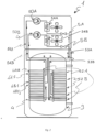
- the heat pump system 1 comprises two separate refrigerant circuits 5A, 5B, and configured so as not to have fluid communication from one refrigerant circuit 5A, 5B to the other refrigerant circuit 5B, 5A.
- Each refrigerant circuit comprising, listed in the sequence travelled by the fluid, one compressor 50A, 50B, one first connection section 51A, 51B, at least one condensing section 52A, 52B, 521A, 521B, at least one second connection section 53A, 53B and one evaporation section 54A, 54B.
- the two refrigerant circuits 5A, 5B share the same heat exchanger body 4, adapted to cooperate and exchange heat with the body 3, 31, 32 to be heated or cooled.
- the heat exchanger body 4 is configured to be traversed by a heat transfer fluid through at least two flow paths 52A, 52B, 521A, 521B each belonging to a respective refrigerant circuit 5A, 5B.
- the heat exchanger 4 may act both as a condenser and as an evaporator depending on the circulation direction of the fluid which, as known, may be reversed.
- a heat exchanger body 4 with micro channel technology and double crossed circuit distribution is described below.
- the heat pump system 1 is described as configured to heat a tank 3, 31, 32, for example a domestic or technical water storage 3, 31, 32 for air conditioning.
- the heat exchanger 4 is a condenser.
- the heat exchanger 4 comprises two flow paths, the first 52A, 521A, comprising a plurality of channels 4A1 1, 4A12, 4A21..., 4Aij, the second 52B, 521B in turn comprising a plurality of channels 4B11, 4B12, 4B21..., 4Bij.
- the channels belonging to the same circuit are connected to each other to create a seamless passage from an inlet connection section 51A, 51B located upstream of each flow path 52A, 52B, 521A, 521B and an outlet connection section 53A, 53B located downstream. At least one part of the channels of each flow path 52A, 52B, 521A, 521B is alternated with channels of the other flow path 52B, 52A, 521B, 521A on a heat exchange surface between the heat exchanger body 4 and the body 3, 31, 32 to be heated or cooled.
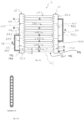
- the channels 4A11, 4A12, 4A21, ... 4Aij, 4B11, 4B12, 4B21, ... 4Bij of the same circuit 5A, 5B are associated in one or more groups 4A1, 4A2, ... 4Aj, 4B1, 4B2, ... 4Bj, see figure 3.a .
- the channels 4A11, 4A12, 4A21, 4Aij, 4B11, 4B12, 4B21, ... 4Bij,in a group 4A1, 4A2, ... 4Aj, 4B1, 4B2, ... 4Bj are placed side by side with each other and in thermal contact with the body 3, 31, 32 to be heated or cooled.
- each flow path 52A, 521A, 52B 521B respectively comprises at least one inlet manifold 7A1, 7A2..., 7Aj and 7B1, 7B2, 7Bj and at least one outlet manifold 8A1, 8A2, 8Aj and 8B1, 8B2..., 8Bj.
- each group 4A1, 4A2..., 4Aj, 4B1, 4B2..., 4Bj is associated with a common input manifold 7A1, 7A2, ... 7Aj, 7B1, 7B2, ... 7Bj and a common output manifold 8A1, 8A2, ... 8Aj, 8B1, 8B2, ... 8Bj.
- Two groups 4B1 and 4B2, 4A1, 4A2 and 4A3, belonging to the same flow path 52A, 52B are consecutive if a fluid exiting the first of the two is introduced into the second of the two via a direct connection or substantial coincidence between the outlet manifold 8B1, 8A2 of the first and the inlet manifold 7B2, 7A3 of the second.
- the channels 4A11, 4A12, 4A21, ... 4Aij, 4B11, 4B12, 4B21, ... 4Bij, in a group 4A1, 4A2, ... 4Aj, 4B1, 4B2, ... 4Bj, are placed side by side and in thermal contact with the body 3, 31, 32 to be heated or cooled.
- the exchanger body 4 comprises a first head manifold 10 comprising several manifolds 7A1, 7B1, 8B2, 8A2, ...7Aj, ...7Bj, 7Bj and dividers 10.1, 10.k adapted to implement separations between the manifolds and a second head manifold 11 comprising several manifolds 8A1, 8B1, 7B2, 7A2, ... 8Aj, ... 8Bj and dividers 11.1, 11. h.
- all the channels 4A11, 4A12, 4A21, ... 4Aij, 4B11, 4B12, 4B21, ... 4Bij are arranged so that their two ends are aligned, along the development of the head manifolds 10, 11.
- Two groups relating to the same flow path, 52A, 52B respectively, may be consecutive and adjacent as, for example, in the case of the groups 4A2 4A3 or 4B1, 4B2; in this case, they are preferably connected by an outlet manifold 8A2 or 8B1 which places the first group 4A2 or respectively 4B1 in fluid communication with the second and consecutive group 4A3 or respectively 4B2.
- each of the aforementioned output manifolds 8A2 or 8B1 acts both directly as an output manifold of the first group and directly as an input manifold 7A3 or respectively 7B2 of the second group.
- the output 8A2 or 8B1 and input 7A3 or 7B2 manifolds are directly connected to each other due by the absence of the respective divider. If two consecutive groups along the same circuit are not adjacent, such as for example the groups 4A1 and 4A2 or 4B2 and 4B3, they are connected by a suitable connection or bypass 9A or respectively 9B, configured to connect the output manifold of the first group 8A1 or 8B2 with the inlet manifold of the second group 7A2 or 7B3 respectively.
- each circuit 5A, 5B there are three groups 4A1, 4A2, 4A3, 4B1, 4B2, 4B3, one fitting with an external connection 9A, 9B, and a direct connection between an outlet manifold 8B1, 8A2 and the subsequent inlet manifold 7B2, 7A3.
- the groups may be different in number than three and not necessarily the same number for each circuit 5A, 5B.
- the channels 4A11, 4A12, 4A21, ... 4Aij, 4B11, 4B12, 4B21, ... 4Bij are made with the micro channel technology.
- a first refrigerant circuit 5A, 5B comprises a greater number of micro channels in a sector of the single exchanger body compared to a second refrigerant circuit 5B, 5A.
- a first refrigerant circuit may comprise a greater number of micro channels in the highest part of the storage 3, 31, 32 compared to a second refrigerant circuit.
- the refrigerant circuit with a greater number of channels in the highest part of the accumulation 3, 31, 32 is sized to have a higher power than the other.
- the direction of passage of the fluid is from top to bottom, i.e. upstream with respect to the motion of water in the tank during the withdrawals.
- the distinct and independent circuits 5A, 5B which define the same heat exchanger body 4 configured with micro channels 4A11, 4A12, 4A21, ... 4Aij, 4B11, 4B12, 4B21, ... 4Bij and with the illustrated structure may be more than two.
- the heat exchanger body 4 may indifferently be either a condenser in case of a heat pump for heating or an evaporator in case of a heat pump for cooling.
- both the evaporator and the condenser may be a single exchanger body made with micro channels configured to define two or more independent circuits without connection points from one circuit to the other and therefore without the possibility of mixing heat transfer fluids.
- the heat pumps may be configured to heat or cool a tank 3, 31, 32, as in the case of a sanitary or technical water heater in figure 2 .
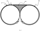
- the same heat exchanger body 4 e.g. a condenser body 4 with micro channel technology and double-crossed circuit distribution may be made to maximise the contact surface with two side-by-side tanks 31, 32 as in figure 4.a and 4.b .
- the heat exchanger body in contact with the tanks may advantageously be provided with thermal bridges 44 which increase the heat exchange along the slots that are formed among the contact line between the two tanks and the exchanger 4.
- thermal bridges 44 may be made with any heat-conductive material.
- the channels of the heat exchanger body 4 belonging to a first refrigerant circuit 5A, 5B mainly exchange heat with a first tank 31, 32, i.e. at least one of the two refrigerant circuits exchanges more heat with a tank than with the other.
- the heat pump system and in particular the double-crossed heat exchanger may be configured so that each tank 31, 32 may be subject to the same or to a different amount of heat exchange. In either case, it is possible that each tank 31, 32 is subject to heat exchange in different proportions with respect to each of the two refrigerant circuits 5A, 5B.
- a variation in the rate of heat exchange from a refrigerant circuit 5A, 5B between the two tanks 31, 32 can be obtained e.g. by a different heat exchange area of a refrigerant circuit 5A, 5B vs a first tank 31, 32 rather than the second tank 32, 31, or by contacting the initial part of the circuit with a first tank 31, 32 rather than the second tank 32, 31.
- the initial part of the circuit is the part in which flows the fluid that is at the highest absolute temperature difference with the tanks inner temperature.
- the two tanks can be connected in series
- the first tank 31 can be the input tank, connected to a cold water pipe
- the second tank 32 can be the output tank connect the a hot water output pipe or faucet
- the input tank 31 is connected in series to the output tank 32 so that water from the cold water pipe can flow from the input tank 31 to the output tank 32.
- a first refrigerant circuit 5A can be configured to exchange, on average, less than 50% of its heat with the first tank 31 and the remaining amount with the second tank 32.
- the first circuit can be configured to exchange 30% or 20% of the heat with the first tank and the remaining with the second (output) tank.
- the first refrigerant circuit 5A is configured to exchange on average more than 50% of its heat with the output tank 32, and the rest with the input tank 31. This allows to concentrate more than half the power of the first heat pump A to the output tank and thereby shorten the time to reach a set temperature in the output tank.
- the second refrigerant circuit 5B is configured to deliver opposed percentages of heat exchange to the two tanks e.g. more than 50% to the input tank.
- each tank can receive the full heat exchange of the two heating circuits 5A, 5B if both heat pumps are turned on, a preferred tank can be preferentially heated if only one heat pump is turned on.
- the heating speed of the output tank can be improved vs the heating speed of the input tank by an appropriate design of the double-crossed refrigerant circuits. It is to be noted that once the output tank 32 approaches the set temperature and until the input tank 31 is below the set temperature an increasing amount of heat exchange naturally occurs with the input tank 31 until the input tank 31 has reached the set temperature. Therefore, both refrigerating circuits 5A, 5B could be configured to exchange more than 50% of their heat with the output tank 32 while the tanks are at the same temperature.
- a possible embodiment of the disclosure is a tank water heating heat pump system comprisingtwo heat pumps and two tanks connected in series a first tank configured to serve as input tank for cold water, the second tank configured to serve as output tank for hot water, each heat pump comprising a refrigerating circuit, the refrigerating circuits configured to exchange heat with the tanks, and at least one refrigerating circuit configured to exchange heat with both tanks, the couple of refrigerating circuits configured to heat the output tank at a higher speed than heating the input tank at least until the output tank has reached a set temperature.
- the two heat exchanging circuits, in case of a water heater are two condenser circuits.
- the two refrigerating circuits have at least part of the channels of each flow path alternated with channels of the other flow path, i.e. it is not necessary that the two refrigerating circuits are of the double crossed type.
- the advantage of this embodiment is the construction simplicity, in case the refrigerating circuits are not of the double crossed type, and the capability to deliver a greater amount of the heat to the output tank, so that hot water for one shower is available in a time shorter than that required to heat the full water volume (both tanks).
- FIG.c A possible diagram of the heating time for each tank is shown in Figure 4.c , this effect is obtained when at least one the condenser heat exchangers is configured to exchange more heat with the output tank, as the output tank approaches the maximum temperature to which the heat pump can heat it, then more heat will be exchanged with the input tank due to the higher temperature difference between the input tank and any of the two condenser heat exchangers.
- a possible embodiment of the double tanks in series version is one in which the percentages of the heat that each refrigerating circuit is configured to exchange with each tank, the tanks being at the same initial temperature, is different from one circuit to the other; i.e. one circuit exchanges more heat with the input tank than the other.
- an aspect of the disclosure is a method to heat a double tank water heater comprising two tanks connected in series a first tank configured to serve as input tank for cold water, the second tank configured to serve as output tank for hot water, and two heat pumps, each heat pump comprising a condenser heat exchanger, the condenser heat exchangers configured to exchange heat with the tanks, and at least one condenser heat exchanger configured to exchange heat with both tanks and at least one condenser heat exchanger configured to exchange more heat with the output tank than with the input tank, the method comprising the steps:
- micro channel heat exchanger body 4 with double-crossed circuit distribution may cooperate with a body with which to exchange heat 3, 31, 32 not exclusively a cylindrical shape.
- An aspect of the disclosure is a method for implementing the heat exchanger body 4 wherein the channels are characterised by a double-crossed circuit distribution.
- the method comprises a channel extrusion step, with preferably cylindrical profiles,
- This process guarantees versatility on the various designs that may be made in terms of number, size and shape of the channel section and dimensions of the exchanger.
Landscapes
- Engineering & Computer Science (AREA)
- Physics & Mathematics (AREA)
- Thermal Sciences (AREA)
- Mechanical Engineering (AREA)
- General Engineering & Computer Science (AREA)
- Chemical & Material Sciences (AREA)
- Combustion & Propulsion (AREA)
- Heat-Exchange Devices With Radiators And Conduit Assemblies (AREA)
- Heat-Pump Type And Storage Water Heaters (AREA)
Priority Applications (1)
| Application Number | Priority Date | Filing Date | Title |
|---|---|---|---|
| CN202411046102.7A CN119436626A (zh) | 2023-08-01 | 2024-08-01 | 具有双制冷剂回路的热水器 |
Applications Claiming Priority (1)
| Application Number | Priority Date | Filing Date | Title |
|---|---|---|---|
| IT102023000016290A IT202300016290A1 (it) | 2023-08-01 | 2023-08-01 | Scalda acqua con doppio circuito frigorifero |
Publications (2)
| Publication Number | Publication Date |
|---|---|
| EP4502502A2 true EP4502502A2 (de) | 2025-02-05 |
| EP4502502A3 EP4502502A3 (de) | 2025-04-30 |
Family
ID=88413745
Family Applications (1)
| Application Number | Title | Priority Date | Filing Date |
|---|---|---|---|
| EP24191366.4A Pending EP4502502A3 (de) | 2023-08-01 | 2024-07-29 | Wasserkocher mit doppeltem kältemittelkreislauf |
Country Status (3)
| Country | Link |
|---|---|
| EP (1) | EP4502502A3 (de) |
| CN (1) | CN119436626A (de) |
| IT (1) | IT202300016290A1 (de) |
Family Cites Families (7)
| Publication number | Priority date | Publication date | Assignee | Title |
|---|---|---|---|---|
| US4201065A (en) * | 1978-12-18 | 1980-05-06 | Carrier Corporation | Variable capacity vapor compression refrigeration system |
| JP2002071170A (ja) * | 2000-08-28 | 2002-03-08 | Fuji Electric Co Ltd | 蓄熱式冷凍空調装置 |
| US20100000709A1 (en) * | 2008-07-02 | 2010-01-07 | Tsung-Che Chang | Heating and heat recovery unit for an air conditioning system |
| CN201875887U (zh) * | 2010-10-01 | 2011-06-22 | 广东芬尼克兹节能设备有限公司 | 双罐热泵热水器 |
| JP5805833B1 (ja) * | 2014-07-28 | 2015-11-10 | 木村工機株式会社 | ヒートポンプ式空気調和機 |
| GB2558943B (en) * | 2017-01-23 | 2019-01-16 | Todd Muxworthy Anthony | Waste-liquid heat recovery |
| US20190168582A1 (en) * | 2017-12-01 | 2019-06-06 | Carrier Corporation | Multi-temperature transportation refrigeration system |
-
2023
- 2023-08-01 IT IT102023000016290A patent/IT202300016290A1/it unknown
-
2024
- 2024-07-29 EP EP24191366.4A patent/EP4502502A3/de active Pending
- 2024-08-01 CN CN202411046102.7A patent/CN119436626A/zh active Pending
Also Published As
| Publication number | Publication date |
|---|---|
| IT202300016290A1 (it) | 2025-02-01 |
| EP4502502A3 (de) | 2025-04-30 |
| CN119436626A (zh) | 2025-02-14 |
Similar Documents
| Publication | Publication Date | Title |
|---|---|---|
| CN207688325U (zh) | 三冷源空调机组 | |
| EP3098540B1 (de) | Wärmepumpenvorrichtung | |
| EP0468046B1 (de) | Wärmepumpe und wärmeübertragungsverfahren für wärmepumpen | |
| CN102087057B (zh) | 可平衡冷媒量的空调系统 | |
| CN102384586B (zh) | 并联式互助除霜空气源热泵热水器 | |
| CN102483243B (zh) | 用于向主系统中循环排水的热泵的对称中间蓄水箱 | |
| CN111251812B (zh) | 车辆的热管理系统及车辆 | |
| WO2014101225A1 (en) | Heat pump water heater | |
| CN101644508A (zh) | 一种多联式空调冷热水多功能系统 | |
| CN108626118A (zh) | 压缩机及具有其的换热系统 | |
| JPWO2020179651A1 (ja) | 車両用バッテリの冷却モジュール | |
| CN104676981B (zh) | 冷媒分流装置、扁管换热器及应用其的空调、热泵热水器 | |
| CN102788447B (zh) | 热泵空调系统 | |
| EP4502502A2 (de) | Wasserkocher mit doppeltem kältemittelkreislauf | |
| CN115218271A (zh) | 一种采暖和制冷均能实现冷媒与水逆流换热的空调系统 | |
| CN102914087A (zh) | 制冷机组的换热系统 | |
| CN204787173U (zh) | 一种换热器、空调系统及集流管 | |
| CN103322732B (zh) | 热泵用喷淋式换热器 | |
| CN208846601U (zh) | 一种冷水热泵机组及空调设备 | |
| EP2642221A2 (de) | Kälteanlage | |
| EP4150265B1 (de) | Kühlsystem | |
| CN104930687A (zh) | 一种换热器、空调系统及集流管 | |
| CN110726196B (zh) | 一种空调冷液一体系统 | |
| CN211011723U (zh) | 一种空调冷液一体系统 | |
| CN202630504U (zh) | 空气能热泵冷暖热一体化设备 |
Legal Events
| Date | Code | Title | Description |
|---|---|---|---|
| PUAI | Public reference made under article 153(3) epc to a published international application that has entered the european phase |
Free format text: ORIGINAL CODE: 0009012 |
|
| STAA | Information on the status of an ep patent application or granted ep patent |
Free format text: STATUS: THE APPLICATION HAS BEEN PUBLISHED |
|
| AK | Designated contracting states |
Kind code of ref document: A2 Designated state(s): AL AT BE BG CH CY CZ DE DK EE ES FI FR GB GR HR HU IE IS IT LI LT LU LV MC ME MK MT NL NO PL PT RO RS SE SI SK SM TR |
|
| PUAL | Search report despatched |
Free format text: ORIGINAL CODE: 0009013 |
|
| AK | Designated contracting states |
Kind code of ref document: A3 Designated state(s): AL AT BE BG CH CY CZ DE DK EE ES FI FR GB GR HR HU IE IS IT LI LT LU LV MC ME MK MT NL NO PL PT RO RS SE SI SK SM TR |
|
| RIC1 | Information provided on ipc code assigned before grant |
Ipc: F25B 39/00 20060101ALI20250324BHEP Ipc: F28D 15/00 20060101ALI20250324BHEP Ipc: F28D 1/04 20060101ALI20250324BHEP Ipc: F25B 25/00 20060101ALI20250324BHEP Ipc: F24D 17/02 20060101ALI20250324BHEP Ipc: F25B 13/00 20060101AFI20250324BHEP |
|
| STAA | Information on the status of an ep patent application or granted ep patent |
Free format text: STATUS: REQUEST FOR EXAMINATION WAS MADE |
|
| 17P | Request for examination filed |
Effective date: 20251029 |