EP4502500A1 - Refrigeration cycle device - Google Patents
Refrigeration cycle device Download PDFInfo
- Publication number
- EP4502500A1 EP4502500A1 EP23780212.9A EP23780212A EP4502500A1 EP 4502500 A1 EP4502500 A1 EP 4502500A1 EP 23780212 A EP23780212 A EP 23780212A EP 4502500 A1 EP4502500 A1 EP 4502500A1
- Authority
- EP
- European Patent Office
- Prior art keywords
- refrigerant
- heat
- flow path
- heat exchanger
- utilization
- Prior art date
- Legal status (The legal status is an assumption and is not a legal conclusion. Google has not performed a legal analysis and makes no representation as to the accuracy of the status listed.)
- Pending
Links
Images




Classifications
-
- F—MECHANICAL ENGINEERING; LIGHTING; HEATING; WEAPONS; BLASTING
- F25—REFRIGERATION OR COOLING; COMBINED HEATING AND REFRIGERATION SYSTEMS; HEAT PUMP SYSTEMS; MANUFACTURE OR STORAGE OF ICE; LIQUEFACTION SOLIDIFICATION OF GASES
- F25B—REFRIGERATION MACHINES, PLANTS OR SYSTEMS; COMBINED HEATING AND REFRIGERATION SYSTEMS; HEAT PUMP SYSTEMS
- F25B41/00—Fluid-circulation arrangements
- F25B41/40—Fluid line arrangements
-
- F—MECHANICAL ENGINEERING; LIGHTING; HEATING; WEAPONS; BLASTING
- F25—REFRIGERATION OR COOLING; COMBINED HEATING AND REFRIGERATION SYSTEMS; HEAT PUMP SYSTEMS; MANUFACTURE OR STORAGE OF ICE; LIQUEFACTION SOLIDIFICATION OF GASES
- F25B—REFRIGERATION MACHINES, PLANTS OR SYSTEMS; COMBINED HEATING AND REFRIGERATION SYSTEMS; HEAT PUMP SYSTEMS
- F25B13/00—Compression machines, plants or systems, with reversible cycle
-
- F—MECHANICAL ENGINEERING; LIGHTING; HEATING; WEAPONS; BLASTING
- F25—REFRIGERATION OR COOLING; COMBINED HEATING AND REFRIGERATION SYSTEMS; HEAT PUMP SYSTEMS; MANUFACTURE OR STORAGE OF ICE; LIQUEFACTION SOLIDIFICATION OF GASES
- F25B—REFRIGERATION MACHINES, PLANTS OR SYSTEMS; COMBINED HEATING AND REFRIGERATION SYSTEMS; HEAT PUMP SYSTEMS
- F25B2313/00—Compression machines, plants or systems with reversible cycle not otherwise provided for
- F25B2313/027—Compression machines, plants or systems with reversible cycle not otherwise provided for characterised by the reversing means
- F25B2313/0272—Compression machines, plants or systems with reversible cycle not otherwise provided for characterised by the reversing means using bridge circuits of one-way valves
Definitions
- the present disclosure relates to a refrigeration cycle apparatus.
- PTL 1 Japanese Unexamined Patent Application Publication No. 7-280375 discloses a refrigeration cycle apparatus (refrigeration cycle apparatus) that suppresses a reduction in heat exchange efficiency in a heat exchanger due to reversal of the flow direction of a refrigerant between heating and cooling in a refrigerant circuit using a zeotropic refrigerant mixture, which is a mixture of two or more types of zeotropic refrigerants.
- PTL 1 discloses a refrigeration cycle apparatus that is provided with two refrigerant flow path switching devices in a refrigerant circuit, and includes a heat exchanger through which a refrigerant flows in a direction opposite to the flow of air in both cases, that is, during heating and cooling operations.
- the present disclosure provides a refrigeration cycle apparatus that uses a zeotropic refrigerant mixture and is capable of both ensuring the heat exchange efficiency in a heat exchanger and suppressing the performance degradation of the apparatus caused by a pressure loss experienced by the refrigerant flowing into the heat exchanger.
- a refrigeration cycle apparatus uses a zeotropic refrigerant mixture as a refrigerant.
- the refrigeration cycle apparatus includes a refrigerant circuit and a control unit.
- the refrigerant circuit includes a heat exchanger that causes heat exchange between air and a refrigerant.
- the control unit performs a first operation that causes the heat exchanger to function as a radiator for the refrigerant and a second operation that causes the heat exchanger to function as an evaporator for the refrigerant.
- the refrigerant flows inside the heat exchanger in a direction opposite to a flow of the air during the first operation and the second operation.
- the refrigerant circuit includes an inflow section through which the refrigerant immediately before flowing into the heat exchanger passes.
- a pressure loss experienced by the refrigerant passing through the inflow section during the first operation is smaller than a pressure loss experienced by the refrigerant passing through the inflow section during the second operation.
- the refrigerant flows inside the heat exchanger in a direction opposite to the flow of the air during heating and cooling operations.
- the heat exchange efficiency in the heat exchanger is ensured even in the refrigerant circuit using a zeotropic refrigerant mixture.
- the pressure loss experienced by a gas refrigerant passing through the inflow section during the first operation is smaller than the pressure loss experienced by a gas-liquid two-phase refrigerant passing through the inflow section during the second operation. Therefore, the refrigeration cycle apparatus suppresses the performance degradation of the apparatus caused by a significant pressure loss experienced by the gas refrigerant immediately before flowing into the heat exchanger during the first operation.
- the refrigeration cycle apparatus is capable of both ensuring the heat exchange efficiency in the heat exchanger and suppressing the performance degradation of the apparatus caused by a pressure loss experienced by the refrigerant flowing into the heat exchanger, while using a zeotropic refrigerant mixture.
- a refrigeration cycle apparatus is the refrigeration cycle apparatus according to the first aspect, in which the inflow section includes a first flow path and a second flow path.
- a pressure loss experienced by the refrigerant passing through the first flow path is smaller than a pressure loss experienced by the refrigerant passing through the second flow path.
- the refrigerant passes through the first flow path and flows into the heat exchanger during the first operation, and passes through the second flow path and flows into the heat exchanger during the second operation.
- the refrigeration cycle apparatus branches the refrigerant immediately before flowing into the heat exchanger into either the first flow path or the second flow path to change the pressure loss experienced by the refrigerant.
- a refrigeration cycle apparatus is the refrigeration cycle apparatus according to the second aspect, in which a first refrigerant pipe included in the first flow path has a flow path area larger than a flow path area of a second refrigerant pipe included in the second flow path.
- the pressure loss experienced by the refrigerant passing through the first flow path is smaller than the pressure loss experienced by the refrigerant passing through the second flow path.
- a refrigeration cycle apparatus is the refrigeration cycle apparatus according to either the second aspect or the third aspect, in which the refrigerant circuit includes a branching section that switches a flow path of the refrigerant to either the first flow path or the second flow path.
- a refrigeration cycle apparatus is the refrigeration cycle apparatus according to the fourth aspect, in which the first flow path includes a fifth check valve provided at a refrigerant pipe on a downstream side.
- the fifth check valve suppresses the refrigerant from backflowing from the second flow path to the first flow path.
- a refrigeration cycle apparatus is the refrigeration cycle apparatus according to the fourth aspect, in which the first flow path includes a control valve provided at a refrigerant pipe on a downstream side.
- control valve suppresses the refrigerant from backflowing from the second flow path to the first flow path.
- a refrigeration cycle apparatus 1 is an apparatus that utilizes a vapor compression refrigeration cycle.
- the refrigeration cycle apparatus 1 is an air-conditioning apparatus that performs a cooling operation that cools air in an air-conditioning target space (not illustrated) and heating that heats the air in the air-conditioning target space.
- the refrigeration cycle apparatus 1 mainly includes one utilization unit 10, one heat source unit 20, a liquid refrigerant connection pipe 30 and a gas refrigerant connection pipe 40, and a control unit 50.
- Fig. 1 is a schematic configuration diagram of the refrigeration cycle apparatus 1.
- Fig. 2 is a block diagram of the control unit 50.
- liquid refrigerant connection pipe 30 and the gas refrigerant connection pipe 40 are pipes that connect the utilization unit 10 and the heat source unit 20 to each other, and constitute a refrigerant circuit 100 together with the respective devices included in the heat source unit 20 and the utilization unit 10.
- the respective devices included in the heat source unit 20 and the utilization unit 10 are connected to each other using first refrigerant pipes 61 or second refrigerant pipes 62.
- the second refrigerant pipes 62 are formed to have flow path areas larger than those of the first refrigerant pipes 61.
- the refrigerant circuit 100 is filled with a zeotropic refrigerant mixture, which is a mixture of two or more types of zeotropic refrigerants.
- a zeotropic refrigerant mixture which is a mixture of two or more types of zeotropic refrigerants.
- R454C is used as the refrigerant.
- the refrigeration cycle apparatus 1 of the present embodiment includes one utilization unit 10, but the number of utilization units 10 is not limited to one.
- the refrigeration cycle apparatus 1 may include a plurality of utilization units 10.
- the refrigeration cycle apparatus 1 of the present embodiment includes one heat source unit 20, but the number of heat source units 20 is not limited to one.
- the refrigeration cycle apparatus 1 may include a plurality of heat source units 20.
- the refrigeration cycle apparatus 1 may be an integrated apparatus in which the heat source unit 20 and the utilization unit 10 are assembled in a single housing, for example.
- the utilization unit 10 cools or heats air Ai in the air-conditioning target space.
- the utilization unit 10 includes a utilization-side heat exchanger 11, a utilization-side fan 12, a utilization-side branching section 13, a utilization-side inflow section 14, and a utilization-side second header Hu2.
- the heating operation is an example of a first operation
- the cooling operation is an example of a second operation.
- the utilization-side heat exchanger 11 causes heat exchange between a refrigerant flowing inside the utilization-side heat exchanger 11 and the air Ai.
- the utilization-side heat exchanger 11 functions as a radiator during the heating operation, and functions as an evaporator during the cooling operation.
- Fig. 3 is a schematic configuration diagram of the utilization-side heat exchanger 11.
- directions in which the refrigerant flows are indicated by open arrows.
- a direction in which the air Ai supplied by the utilization-side fan 12 flows is indicated by a hatched arrow.
- a horizontal direction, a vertical direction, and respective directions such as up, down, windward, and leeward correspond to directions indicated by arrows illustrated in Fig. 3 .
- the utilization-side heat exchanger 11 is a fin-and-tube heat exchanger including a plurality of tubular heat transfer tubes 11hp, a plurality of fins 11f, a plurality of first connecting tubes 11ca, and second connecting tubes 11cb.
- the heat transfer tubes 11hp are disposed so as to penetrate the plurality of fins 11f and extend along a first direction (in the present embodiment, the horizontal direction).
- the plurality of fins 11f are disposed in parallel to each other at predetermined intervals along the first direction.
- the utilization-side heat exchanger 11 includes three paths 11pa, 11pb, and 11pc.
- the paths 11pa, 11pb, and 11pc have an identical shape.
- the paths 11pa, 11pb, and 11pc each include a plurality of the heat transfer tubes 11hp, a plurality of the first connecting tubes 11ca, and the second connecting tube 11cb.
- the paths 11pa, 11pb, and 11pc each have an inlet 11i and an outlet 11o.
- the paths 11pa, 11pb, and 11pc are disposed along the first direction.
- the paths 11pa, 11pb, and 11pc each include a heat transfer tube group Ru1 and a heat transfer tube group Ru2 in each of which a plurality of the heat transfer tubes 11hp are arranged in parallel to each other along a second direction (in the present embodiment, the vertical direction).
- the heat transfer tube groups Ru1 and Ru2 each include four heat transfer tubes 11hp.
- the paths 11pa, 11pb, and 11pc are each formed such that the heat transfer tubes 11hp disposed in four stages in the second direction are arranged in two rows in the first direction.
- the heat transfer tube groups Ru1 and Ru2 are disposed such that a plane including center axes of a plurality of the heat transfer tubes 11hp included in the heat transfer tube group Ru1 and a plane including center axes of a plurality of the heat transfer tubes 11hp included in the heat transfer tube group Ru2 are parallel to each other at a predetermined interval. Furthermore, the heat transfer tube groups Ru1 and Ru2 are disposed such that the planes including the center axes of the plurality of heat transfer tubes 11hp included in the heat transfer tube groups Ru1 and Ru2 are orthogonal to the direction in which the air Ai supplied by the utilization-side fan 12 flows (in the present embodiment, the horizontal direction).
- the heat transfer tube group Ru1 is disposed on the windward side of the heat transfer tube group Ru2 in the direction in which the air Ai supplied by the utilization-side fan 12 flows.
- the inlet 11i is an opening of an end portion of the heat transfer tube 11hp disposed at the uppermost position in the heat transfer tube group Ru2.
- the inlet 11i is connected to the utilization-side inflow section 14.
- the outlet 11o is an opening of an end portion of the heat transfer tube 11hp disposed at the lowermost position in the heat transfer tube group Ru1.
- the outlet 11o is connected to the utilization-side second header Hu2 via a first refrigerant pipe 61.
- Each first connecting tube 11ca is provided at an end portion of the heat transfer tube 11hp so that the refrigerant flowing to the end portion of the heat transfer tube 11hp can flow into an adjacent heat transfer tube 11hp of another stage along the second direction.
- the second connecting tube 11cb communicates the adjacent heat transfer tube groups Ru1 and Ru2 to each other. Specifically, the second connecting tube 11cb is provided so as to communicate an end portion of the heat transfer tube 11hp disposed at the lowermost position in the heat transfer tube group Ru2 and an end portion of the heat transfer tube 11hp disposed at the uppermost position in the heat transfer tube group Ru1 to each other.
- the utilization-side branching section 13 switches the flow path of the refrigerant that flows out of the heat source unit 20 and the flow path of the refrigerant that flows out of the utilization-side heat exchanger 11 between the heating operation and the cooling operation.
- the utilization-side branching section 13 is connected to the liquid refrigerant connection pipe 30, the gas refrigerant connection pipe 40, the utilization-side inflow section 14, and the utilization-side second header Hu2.
- the utilization-side branching section 13 includes a first check valve Vu1, a second check valve Vu2, a third check valve Vu3, and a fourth check valve Vu4.
- the first check valve Vu1, the second check valve Vu2, the third check valve Vu3, and the fourth check valve Vu4 each have an inlet and an outlet.
- the first check valve Vu1, the second check valve Vu2, the third check valve Vu3, and the fourth check valve Vu4 each allow the refrigerant to flow from the inlet to the outlet (in a direction indicated by each arrow in the drawing), and each restrict the refrigerant from flowing in a direction opposite to the direction indicated by the arrow.
- the outlet of the first check valve Vu1 is connected to the inlet of the second check valve Vu2.
- the outlet of the third check valve Vu3 is connected to the inlet of the fourth check valve Vu4.
- the inlet of the first check valve Vu1 and the inlet of the third check valve Vu3 are connected to the utilization-side second header Hu2 via a second refrigerant pipe 62.
- the outlet of the first check valve Vu1 and the inlet of the second check valve Vu2 are connected to the liquid refrigerant connection pipe 30 via a first refrigerant pipe 61.
- the outlet of the third check valve Vu3 and the inlet of the fourth check valve Vu4 are connected to the gas refrigerant connection pipe 40 via a second refrigerant pipe 62.
- the outlet of the second check valve Vu2 is connected to a second flow path 14b (described later) of the utilization-side inflow section 14 via a first refrigerant pipe 61.
- the outlet of the fourth check valve Vu4 is connected to a first flow path 14a (described later) of the utilization-side inflow section 14 via a second refrigerant pipe 62.
- the utilization-side inflow section 14 is a flow path through which the refrigerant immediately before flowing into the utilization-side heat exchanger 11 passes.
- the utilization-side inflow section 14 includes the first flow path 14a and the second flow path 14b.
- the utilization-side inflow section 14 is configured such that a pressure loss experienced by the refrigerant passing through the first flow path 14a is smaller than a pressure loss experienced by the refrigerant passing through the second flow path 14b.
- the first flow path 14a is a flow path through which the refrigerant passes during an operation that causes the utilization-side heat exchanger 11 to function as a radiator for the refrigerant (specifically, the heating operation).
- the refrigerant that flows into the first flow path 14a is distributed to the respective paths 11pa, 11pb, and 11pc by the first flow path 14a.
- the first flow path 14a includes a utilization-side first header Hu1 and a plurality of fifth check valves Vu5.
- the utilization-side first header Hu1 is a tubular member through which the refrigerant flows.
- the utilization-side first header Hu1 is connected to the utilization-side branching section 13 (specifically, the outlet of the fourth check valve Vu4) via the second refrigerant pipe 62, and is connected to inlets of the fifth check valves Vu5 via second refrigerant pipes 62.
- the fifth check valves Vu5 each allow the refrigerant to flow from the inlet to an outlet (in a direction indicated by each arrow in the drawing), and each restrict the refrigerant from flowing in a direction opposite to the direction indicated by the arrow.
- the inlets of the fifth check valves Vu5 are connected to the utilization-side first header Hu1 via the second refrigerant pipes 62.
- the fifth check valves Vu5 suppress backflow of the refrigerant that comes from the utilization-side first header Hu1.
- the outlets of the fifth check valves Vu5 are connected to the respective inlets 11i of the paths 11pa, 11pb, and 11pc via second refrigerant pipes 62.
- the first flow path 14a includes three fifth check valves Vu5, and the respective three fifth check valves Vu5 are connected to the utilization-side first header Hu1 via individual second refrigerant pipes 62.
- the number of fifth check valves Vu5 included in the first flow path 14a is not limited to three, and may be two, four, or more, for example.
- the second flow path 14b is a flow path through which the refrigerant passes during an operation that causes the utilization-side heat exchanger 11 to function as an evaporator for the refrigerant (specifically, the cooling operation).
- the refrigerant that flows into the second flow path 14b is distributed to the respective paths 11pa, 11pb, and 11pc by the second flow path 14b.
- the second flow path 14b includes a distributor Du and three flow rate adjustment sections Cu.
- the distributor Du is a member that distributes the refrigerant that flows out of the utilization-side branching section 13.
- the distributor Du is connected to the utilization-side branching section 13 (specifically, the second check valve Vu2) via the first refrigerant pipe 61, and is connected to inlets of the flow rate adjustment sections Cu via first refrigerant pipes 61.
- the flow rate adjustment sections Cu are connected to the respective paths 11pa, 11pb, and 11pc of the utilization-side heat exchanger 11, and adjust flow rates of the refrigerant flowing into the respective paths 11pa, 11pb, and 11pc.
- the flow rate adjustment sections Cu are narrow tubes (capillary tubes) each having an inlet and an outlet.
- the outlets of the flow rate adjustment sections Cu are connected to the respective inlets 11i of the paths 11pa, 11pb, and 11pc.
- the flow rate adjustment section Cu is formed to have a flow path area smaller than those of the first refrigerant pipe 61 and the second refrigerant pipe 62.
- a pressure loss experienced by the refrigerant when the refrigerant passes through the flow rate adjustment section Cu is larger than a pressure loss that the refrigerant receives when the refrigerant passes through the first refrigerant pipe 61 and the second refrigerant pipe 62.
- the lengths and the flow path areas of the three flow rate adjustment sections Cu may be different from each other.
- the first flow path 14a includes the utilization-side first header Hu1 and the fifth check valves Vu5 connected via the second refrigerant pipes 62
- the second flow path 14b includes the flow rate adjustment sections Cu in each of which the pressure loss experienced by the refrigerant passing through the flow rate adjustment section Cu is larger than that of the second refrigerant pipe 62.
- the pressure loss experienced by the refrigerant passing through the first flow path 14a is smaller than the pressure loss experienced by the refrigerant passing through the second flow path 14b.
- the utilization-side second header Hu2 is a tubular member through which the refrigerant flows.
- the utilization-side second header Hu2 is connected to the outlets 11o of the utilization-side heat exchanger 11 via a plurality of the first refrigerant pipes 61, and is connected to the utilization-side branching section 13 (specifically, the inlet of the first check valve Vu1 and the inlet of the third check valve Vu3) via the second refrigerant pipe 62.
- the refrigerant that flows out of the utilization-side inflow section 14 flows into the uppermost heat transfer tubes 11hp in the heat transfer tube groups Ru2 from the respective inlets 11i of the paths 11pa, 11pb, and 11pc.
- the refrigerant that flows into the heat transfer tube group Ru2 alternately passes through the heat transfer tube 11hp and the first connecting tube 11ca and moves downward while meandering through the heat transfer tube group Ru2.
- the refrigerant that flows into the lowermost heat transfer tube 11hp in the heat transfer tube group Ru2 passes through the second connecting tube 11cb, and flows into the uppermost heat transfer tube 11hp in the heat transfer tube group Ru1.
- the refrigerant that flows into the heat transfer tube group Ru1 also moves downward while meandering through the heat transfer tube group Ru1, passes through the outlet 11o, and flows out to the utilization-side second header Hu2.
- the refrigerant flowing through each of the paths 11pa, 11pb, and 11pc flows inside the utilization-side heat exchanger 11 in the order from the heat transfer tube group Ru2 to the heat transfer tube group Ru1, in a direction opposite to the flow of the air Ai supplied by the utilization-side fan 12.
- the heat source unit 20 is disposed outside the air-conditioning target space.
- the heat source unit 20 includes a heat-source-side heat exchanger 21, a heat-source-side fan 22, a heat-source-side branching section 23, a heat-source-side inflow section 24, a heat-source-side second header Hh2, a flow direction switching mechanism 25, a compressor 26, an expansion mechanism 27, a first shut-off valve 28, and a second shut-off valve 29.
- the cooling operation is an example of the first operation
- the heating operation is an example of the second operation.
- the heat-source-side heat exchanger 21 causes heat exchange between the refrigerant flowing inside the heat-source-side heat exchanger 21 and air Ao outside the air-conditioning target space.
- the heat-source-side heat exchanger 21 functions as a radiator during the cooling operation, and functions as an evaporator during the heating operation.
- Fig. 4 is a schematic configuration diagram of the heat-source-side heat exchanger 21.
- directions in which the refrigerant flows are indicated by open arrows.
- a direction in which the air Ao supplied by the heat-source-side fan 22 flows is indicated by a hatched arrow.
- the horizontal direction, the vertical direction, and respective directions such as up, down, windward, and leeward, referred to in the following description correspond to directions indicated by arrows illustrated in Fig. 4 .
- the heat-source-side heat exchanger 21 is a fin-and-tube heat exchanger including a plurality of tubular heat transfer tubes 21hp, a plurality of fins 21f, a plurality of first connecting tubes 21ca, and second connecting tubes 21cb.
- the heat transfer tubes 21hp are disposed so as to penetrate the plurality of fins 21f and extend along the first direction.
- the plurality of fins 21f are disposed in parallel to each other at predetermined intervals along the first direction.
- the heat-source-side heat exchanger 21 includes three paths 21pa, 21pb, and 21pc.
- the three paths 21pa, 21pb, and 21pc each have an identical shape.
- the three paths 21pa, 21pb, and 21pc each have an individual refrigerant flow path, including a plurality of the heat transfer tubes 21hp, a plurality of the first connecting tubes 21ca, and the second connecting tube 21cb.
- the paths 21pa, 21pb, and 21pc each have an inlet 21i and an outlet 21o.
- the three paths 21pa, 21pb, and 21pc are arranged along the first direction.
- the paths 21pa, 21pb, and 21pc each include a heat transfer tube group Rh1 and a heat transfer tube group Rh2 in each of which a plurality of the heat transfer tubes 21hp are arranged in parallel to each other along the second direction.
- the heat transfer tube groups Rh1 and Rh2 each include four heat transfer tubes 21hp.
- the paths 21pa, 21pb, and 21pc are each formed such that the heat transfer tubes 21hp disposed in four stages in the second direction are arranged in two rows in the first direction.
- the heat transfer tube groups Rh1 and Rh2 are disposed such that a plane including center axes of a plurality of the heat transfer tubes 21hp included in the heat transfer tube group Rh1 and a plane including center axes of a plurality of the heat transfer tubes 21hp included in the heat transfer tube group Rh2 are parallel to each other at a predetermined interval. Furthermore, the heat transfer tube groups Ru1 and Ru2 are disposed such that the planes including the center axes of the plurality of heat transfer tubes 21hp included in the heat transfer tube groups Ru1 and Ru2 are orthogonal to the direction in which the air Ao supplied by the heat-source-side fan 22 flows (in the present embodiment, the horizontal direction).
- the heat transfer tube group Rh1 is disposed on the windward side of the heat transfer tube group Rh2 in the direction in which the air Ao supplied by the heat-source-side fan 22 flows.
- the inlet 21i is an opening of an end portion of the heat transfer tube 21hp disposed at the uppermost position in the heat transfer tube group Rh2.
- the inlet 21i is connected to the heat-source-side inflow section 24.
- the outlet 21o is an opening of an end portion of the heat transfer tube 21hp disposed at the lowermost position in the heat transfer tube group Rh1.
- the outlet 21o is connected to the heat-source-side second header Hh2 via a first refrigerant pipe 61.
- Each first connecting tube 21ca is provided at an end portion of the heat transfer tube 21hp so that the refrigerant flowing to the end portion of the heat transfer tube 21hp can flow into an adjacent heat transfer tube 21hp of another stage along the second direction.
- the second connecting tube 21cb communicates the adjacent heat transfer tube groups Rh1 and Rh2 to each other.
- the second connecting tube 21u is provided so as to communicate an end portion of the heat transfer tube 21hp disposed at the lowermost position in the heat transfer tube group Rh2 and an end portion of the heat transfer tube 21hp disposed at the uppermost position in the heat transfer tube group Rh1 to each other.
- the heat-source-side fan 22 is a fan that supplies the air Ao (heat source air) to the heat-source-side heat exchanger 21.
- the heat-source-side fan 22 is driven by a fan motor 22m (see Fig. 2 ).
- the control unit 50 controls the number of rotations of the fan motor 22m to control an amount of the air Ao supplied to the heat-source-side heat exchanger 21.
- the heat-source-side branching section 23 switches the flow path of the refrigerant that flows out of the utilization unit 10 and the flow path of the refrigerant that flows out of the heat-source-side heat exchanger 21 between the heating operation and the cooling operation.
- the heat-source-side branching section 23 is connected to the liquid refrigerant connection pipe 30, the gas refrigerant connection pipe 40, the utilization-side inflow section 14, and the utilization-side second header Hu2.
- the heat-source-side branching section 23 includes a first check valve Vh1, a second check valve Vh2, a third check valve Vh3, and a fourth check valve Vh4.
- the first check valve Vh1, the second check valve Vh2, the third check valve Vh3, and the fourth check valve Vh4 each have an inlet and an outlet.
- the first check valve Vh1, the second check valve Vh2, the third check valve Vh3, and the fourth check valve Vh4 each allow the refrigerant to flow from the inlet to the outlet (in a direction indicated by each arrow in the drawing), and each restrict the refrigerant from flowing in a direction opposite to the direction indicated by the arrow.
- the outlet of the first check valve Vh1 is connected to the inlet of the second check valve Vh2.
- the outlet of the third check valve Vh3 is connected to the inlet of the fourth check valve Vh4.
- the inlet of the first check valve Vh1 and the inlet of the third check valve Vh3 are connected to the heat-source-side second header Hh2 via a first refrigerant pipe 61.
- the outlet of the first check valve Vh1 and the inlet of the second check valve Vh2 are connected to the expansion mechanism 27 via a first refrigerant pipe 61.
- the outlet of the third check valve Vh3 and the inlet of the fourth check valve Vh4 are connected to a third port P3 (described later) of the flow direction switching mechanism 25 via a second refrigerant pipe 62.
- the outlet of the second check valve Vh2 is connected to a second flow path 24b (described later) of the heat-source-side inflow section 24 via a first refrigerant pipe 61.
- the outlet of the fourth check valve Vh4 is connected to a first flow path 24a (described later) of the heat-source-side inflow section 24 via a second refrigerant pipe 62.
- the heat-source-side inflow section 24 is a flow path through which the refrigerant immediately before flowing into the heat-source-side heat exchanger 21 passes.
- the heat-source-side inflow section 24 includes the first flow path 24a and the second flow path 24b.
- the heat-source-side inflow section 24 is configured such that a pressure loss experienced by the refrigerant passing through the first flow path 24a is smaller than a pressure loss experienced by the refrigerant passing through the second flow path 24b.
- the first flow path 24a is a flow path through which the refrigerant passes during an operation that causes the heat-source-side heat exchanger 21 to function as a radiator for the refrigerant (specifically, the cooling operation).
- the refrigerant that flows into the first flow path 24a is distributed to the respective paths 21pa, 21pb, and 21pc by the first flow path 24a.
- the first flow path 24a includes a heat-source-side first header Hh1 and a plurality of fifth check valves Vh5.
- the heat-source-side first header Hh1 is a tubular member through which the refrigerant flows.
- the heat-source-side first header Hh1 is connected to the heat-source-side branching section 23 (specifically, the outlet of the fourth check valve Vh4) via the second refrigerant pipe 62, and is connected to inlets of the fifth check valves Vh5 via second refrigerant pipes 62.
- the fifth check valves Vh5 each allow the refrigerant to flow from the inlet to an outlet (in a direction indicated by each arrow in the drawing), and each restrict the refrigerant from flowing in a direction opposite to the direction indicated by the arrow.
- the inlets of the fifth check valves Vh5 are connected to the heat-source-side first header Hh1 via the second refrigerant pipes 62.
- the fifth check valves Vh5 suppress backflow of the refrigerant that comes from the heat-source-side first header Hh1.
- the outlets of the fifth check valves Vh5 are connected to the respective inlets 21i of the paths 21pa, 21pb, and 21pc via second refrigerant pipes 62.
- the first flow path 24a includes three fifth check valves Vh5, and the respective three fifth check valves Vh5 are connected to the heat-source-side first header Hh1 via individual second refrigerant pipes 62.
- the number of fifth check valves Vh5 included in the first flow path 24a is not limited to three, and may be two, four, or more, for example.
- the second flow path 24b is a flow path through which the refrigerant passes during an operation that causes the heat-source-side heat exchanger 21 to function as an evaporator for the refrigerant (specifically, the heating operation).
- the refrigerant that flows into the second flow path 24b is distributed to the respective paths 21pa, 21pb, and 21pc by the second flow path 24b.
- the second flow path 24b includes a distributor Dh and three flow rate adjustment sections Ch.
- the distributor Dh is a member that distributes the refrigerant that flows out of the heat-source-side branching section 23.
- the distributor Dh is connected to the heat-source-side branching section 23 (specifically, the second check valve Vh2) via the first refrigerant pipe 61, and is connected to inlets of the flow rate adjustment sections Ch via first refrigerant pipes 61.
- the flow rate adjustment sections Ch are connected to the respective paths 21pa, 21pb, and 21pc of the heat-source-side heat exchanger 21, and adjust flow rates of the refrigerant flowing into the respective paths 21pa, 21pb, and 21pc.
- the flow rate adjustment sections Ch are narrow tubes (capillary tubes) each having an inlet and an outlet.
- the outlets of the flow rate adjustment sections Ch are connected to the respective inlets 21i of the paths 21pa, 21pb, and 21pc.
- the flow rate adjustment section Ch is formed to have a flow path area smaller than those of the first refrigerant pipe 61 and the second refrigerant pipe 62.
- a pressure loss experienced by the refrigerant when the refrigerant passes through the flow rate adjustment section Ch is larger than a pressure loss that the refrigerant receives when the refrigerant passes through the first refrigerant pipe 61 and the second refrigerant pipe 62.
- the lengths and the flow path areas of the three flow rate adjustment sections Ch may be different from each other.
- the first flow path 24a includes the heat-source-side first header Hh1 and the fifth check valves Vh5 connected via the second refrigerant pipes 62
- the second flow path 24b includes the flow rate adjustment sections Cu in each of which the pressure loss experienced by the refrigerant passing through the flow rate adjustment section Cu is larger than that of the second refrigerant pipe 62.
- the pressure loss experienced by the refrigerant passing through the first flow path 24a is smaller than the pressure loss experienced by the refrigerant passing through the second flow path 24b.
- the heat-source-side second header Hh2 is a tubular member through which the refrigerant flows.
- the heat-source-side second header Hh2 is connected to the outlets 21o of the heat-source-side heat exchanger 21 via a plurality of the first refrigerant pipes 61, and is connected to the heat-source-side branching section 23 (specifically, the inlet of the first check valve Vh1 and the inlet of the third check valve Vh3) via the first refrigerant pipe 61.
- the flow direction switching mechanism 25 switches the flow direction of the refrigerant in the refrigerant circuit 100.
- the flow direction switching mechanism 25 is a four-way switching valve that switches between a first state and a second state.
- the flow direction switching mechanism 25 includes a first port P1, a second port P2, the third port P3, and a fourth port P4.
- the control unit 50 switches the flow direction switching mechanism 25 between the first state and the second state.
- the first port P1 is connected to the gas refrigerant connection pipe 40 via a second refrigerant pipe 62.
- the second port P2 is connected to a discharge pipe 26b (described later) of the compressor 26 via a first refrigerant pipe 61.
- the third port P3 is connected to the heat-source-side branching section 23 (specifically, the outlet of the third check valve Vh3 and the inlet of the fourth check valve Vh4) via the second refrigerant pipe 62.
- the fourth port P4 is connected to a suction pipe 26a (described later) of the compressor 26 via a second refrigerant pipe 62.
- the flow direction switching mechanism 25 communicates the first port P1 and the second port P2 with each other, and communicates the third port P3 and the fourth port P4 with each other (see solid lines in the flow direction switching mechanism 25 in Fig. 1 ).
- the flow direction switching mechanism 25 communicates the first port P1 and the third port P3 with each other, and communicates the second port P2 and the fourth port P4 with each other (see broken lines in the flow direction switching mechanism 25 in Fig. 1 ).
- the flow direction switching mechanism 25 is not limited to the four-way switching valve.
- the flow direction switching mechanism 25 may be configured by combining a plurality of control valves and refrigerant pipes so as to achieve switching of the flow direction of the refrigerant described above.
- the compressor 26 sucks a low-pressure refrigerant in the refrigeration cycle from the suction pipe 26a, compresses the refrigerant by using a compression mechanism (not illustrated), and discharges the compressed refrigerant from the discharge pipe 26b.
- the compression mechanism of the compressor 26 is driven by a compression mechanism motor 26m (see Fig. 2 ).
- the control unit 50 controls the number of rotations of the compression mechanism motor 26m to control a capacity of the compressor 26.
- the suction pipe 26a of the compressor 26 is connected to the fourth port P4 of the flow direction switching mechanism 25 via the second refrigerant pipe 62.
- the discharge pipe 26b of the compressor 26 is connected to the second port P2 of the flow direction switching mechanism 25 via the first refrigerant pipe 61.
- the expansion mechanism 27 adjusts the pressure and the flow rate of the refrigerant passing through the expansion mechanism 27.
- the expansion mechanism 27 is a variable-opening-degree electric expansion mechanism.
- the control unit 50 controls the opening degree of the expansion mechanism 27.
- One end of the expansion mechanism 27 is connected to the liquid refrigerant connection pipe 30 via a first refrigerant pipe 61.
- the other end of the expansion mechanism 27 is connected to the heat-source-side branching section 23 (specifically, the outlet of the first check valve Vh1 and the inlet of the second check valve Vh2) via the first refrigerant pipe 61.
- the expansion mechanism 27 is not limited to the electric expansion mechanism, and may be a temperature sensing cylinder type expansion mechanism or a capillary tube, for example.
- the utilization unit 10 may include an expansion mechanism similar to the expansion mechanism 27.
- the first shut-off valve 28 and the second shut-off valve 29 are valves, each of which shuts off the refrigerant pipe to interrupt the flow of the refrigerant.
- the first shut-off valve 28 and the second shut-off valve 29 are manually operated valves, and are opened and closed by an operator during the installation or similar operations of the refrigeration cycle apparatus 1.
- the first shut-off valve 28 is provided in the first refrigerant pipe 61 that connects the expansion mechanism 27 and the liquid refrigerant connection pipe 30 to each other.
- the second shut-off valve 29 is provided in the second refrigerant pipe 62 that connects the flow direction switching mechanism 25 and the gas refrigerant connection pipe 40 to each other.
- the refrigerant that flows out of the heat-source-side inflow section 24 flows into the uppermost heat transfer tubes 21hp in the heat transfer tube groups Rh2 from the respective inlets 21i of the paths 21pa, 21pb, and 21pc.
- the refrigerant that flows into the heat transfer tube group Rh2 alternately passes through the heat transfer tube 21hp and the first connecting tube 21ca and moves downward while meandering through the heat transfer tube group Rh2.
- the refrigerant that flows into the lowermost heat transfer tube 21hp in the heat transfer tube group Rh2 passes through the second connecting tube 21cb, and flows into the lowermost heat transfer tube 21hp in the heat transfer tube group Rh1.
- the refrigerant that flows into the heat transfer tube group Rh1 also moves downward while meandering through the heat transfer tube group Rh1, thereafter, passes through the outlet 21o, and flows out to the heat-source-side second header Hh2.
- the refrigerant flowing through each of the paths 21pa, 21pb, and 21pc flows inside the heat-source-side heat exchanger 21 in the order from the heat transfer tube group Rh2 to the heat transfer tube group Rh1, in a direction opposite to the flow of the air Ao supplied by the heat-source-side fan 22.
- the liquid refrigerant connection pipe 30 and the gas refrigerant connection pipe 40 are pipes that connect the utilization unit 10 and the heat source unit 20 to each other. More specifically, the liquid refrigerant connection pipe 30 is connected to the outlet of the first check valve Vu1 and the inlet of the second check valve Vu2 via the first refrigerant pipe 61, and is connected to one end of the expansion mechanism 27 via the first refrigerant pipe 61.
- the gas refrigerant connection pipe 40 is connected to the outlet of the third check valve Vu3 and the inlet of the fourth check valve Vu4 via the second refrigerant pipe 62, and is connected to the first port P1 of the flow direction switching mechanism 25 via the second refrigerant pipe 62.
- the gas refrigerant connection pipe 40 is formed to have a flow path area larger than that of the liquid refrigerant connection pipe 30.
- the liquid refrigerant connection pipe 30 and the gas refrigerant connection pipe 40 are pipes mounted at an installation site of the refrigeration cycle apparatus 1 during the installation of the refrigeration cycle apparatus 1, for example.
- the control unit 50 is electrically connected so as to be able to control the utilization-side fan 12, the heat-source-side fan 22, the flow direction switching mechanism 25, the compressor 26, and the expansion mechanism 27. Although details will be described later, when the refrigeration cycle apparatus 1 performs the cooling operation and the heating operation, the control unit 50 controls these devices.
- the control unit 50 is implemented by a computer.
- the control unit 50 includes a control arithmetic device and a storage device (both not illustrated).
- a control arithmetic device a processor such as a CPU or a GPU can be used.
- the control arithmetic device reads a program stored in the storage device and executes predetermined image processing or arithmetic processing in accordance with the program.
- the control arithmetic device can write an arithmetic result in the storage device and read information stored in the storage device in accordance with the program.
- the storage device can be used as a database.
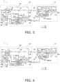
- FIG. 5 is a schematic configuration diagram illustrating a flow of the refrigerant during a heating operation.
- Fig. 6 is a schematic configuration diagram illustrating a flow of the refrigerant during a cooling operation. In Figs. 5 and 6 , the flow of the refrigerant is indicated by arrows.
- the control unit 50 sets the flow direction switching mechanism 25 to the first state, starts operations of the utilization-side fan 12, the heat-source-side fan 22, and the compressor 26, and controls the opening degree of the expansion mechanism 27.
- the refrigerant flows through the refrigerant circuit 100 as described below.
- the refrigerant that flows into the utilization-side branching section 13 is restricted from flowing to the inlet of the third check valve Vu3 while passing through the fourth check valve Vu4, and flows into the first flow path 14a of the utilization-side inflow section 14.
- the refrigerant that flows into the first flow path 14a flows into the utilization-side heat exchanger 11 from the inlets 11i by way of the utilization-side first header Hu1 and the fifth check valves Vu5.
- the refrigerant that flows into the utilization-side heat exchanger 11 releases heat by exchanging heat with the air Ai supplied by the utilization-side fan 12, and becomes a high-pressure liquid refrigerant.
- the utilization-side heat exchanger 11 functions as a radiator in the refrigerant circuit 100.
- the temperature of the air Ai supplied to the utilization-side heat exchanger 11 rises as the air Ai exchanges heat with the refrigerant that flows into the utilization-side heat exchanger 11, and thereafter, the air Ai is blown out of the utilization unit 10.
- the high-pressure liquid refrigerant that flows out of the utilization-side heat exchanger 11 flows into the inlet of the first check valve Vu1 of the utilization-side branching section 13 by way of the utilization-side second header Hu2.
- the refrigerant that passes through the first check valve Vu1 flows into the heat source unit 20 by way of the liquid refrigerant connection pipe 30.
- the refrigerant that flows into the heat source unit 20 flows into the outlet of the first check valve Vh1 and the inlet of the second check valve Vh2 of the heat-source-side branching section 23 by way of the expansion mechanism 27.
- the refrigerant is depressurized to a pressure close to the suction pressure of the compressor 26 when passing through the expansion mechanism 27, and becomes a refrigerant in a gas-liquid two-phase state.
- the refrigerant that flows into the heat-source-side branching section 23 is restricted from flowing to the inlet of the first check valve Vh1 while passing through the second check valve Vh2, and flows into the second flow path 24b of the heat-source-side inflow section 24.
- the refrigerant that flows into the second flow path 24b flows into the heat-source-side heat exchanger 21 from the inlets 21i by way of the distributor Dh and the flow rate adjustment sections Ch.
- the refrigerant that is in a low-pressure gas-liquid two-phase state and flows into the heat-source-side heat exchanger 21 evaporates by exchanging heat with the air Ao supplied by the heat-source-side fan 22, and becomes a low-pressure gas refrigerant.
- the heat-source-side heat exchanger 21 functions as an evaporator in the refrigerant circuit 100.
- the low-pressure gas refrigerant that flows out of the heat-source-side heat exchanger 21 flows into the inlet of the third check valve Vh3 of the heat-source-side branching section 23 by way of the heat-source-side second header Hh2.
- the refrigerant that passes through the third check valve Vh3 flows into the flow direction switching mechanism 25 from the third port P3.
- the refrigerant that flows into the flow direction switching mechanism 25 flows out from the fourth port P4, and thereafter, is sucked into the compressor 26 from the suction pipe 26a again.
- the refrigerant passes through the first flow path 14a immediately before flowing into the utilization-side heat exchanger 11, and passes through the second flow path 24b immediately before flowing into the heat-source-side heat exchanger 21. More specifically, during the heating operation, the gas refrigerant immediately before flowing into the utilization-side heat exchanger 11 that functions as a radiator is distributed to the respective paths 11pa, 11pb, and 11pc in the first flow path 14a in which the pressure loss experienced is smaller than that of the second flow path 14b.
- the gas-liquid two-phase refrigerant immediately before flowing into the heat-source-side heat exchanger 21 that functions as an evaporator is distributed to the respective paths 21pa, 21pb, and 21pc in the second flow path 24b in which the pressure loss experienced is larger than that of the first flow path 24a.
- the control unit 50 sets the flow direction switching mechanism 25 to the second state, starts operations of the utilization-side fan 12, the heat-source-side fan 22, and the compressor 26, and controls the opening degree of the expansion mechanism 27.
- the refrigerant flows through the refrigerant circuit 100 as described below.
- the refrigerant that flows into the heat-source-side branching section 23 is restricted from flowing into the inlet of the third check valve Vh3 while passing through the fourth check valve Vh4, and flows into the first flow path 24a of the heat-source-side inflow section 24.
- the refrigerant that flows into the first flow path 24a flows into the heat-source-side heat exchanger 21 from the inlets 21i by way of the heat-source-side first header Hh1 and the fifth check valves Vh5.
- the refrigerant that flows into the heat-source-side heat exchanger 21 releases heat by exchanging heat with the air Ao supplied by the heat-source-side fan 22, and becomes a high-pressure liquid refrigerant.
- the heat-source-side heat exchanger 21 functions as a radiator in the refrigerant circuit 100.
- the high-pressure liquid refrigerant that flows out of the heat-source-side heat exchanger 21 flows into the inlet of the first check valve Vh1 of the heat-source-side branching section 23 by way of the heat-source-side second header Hh2.
- the refrigerant that passes through the first check valve Vu1 flows into the utilization unit 10 by way of the expansion mechanism 27 and the liquid refrigerant connection pipe 30.
- the refrigerant is depressurized to a pressure close to the suction pressure of the compressor 26 when passing through the expansion mechanism 27, and becomes a refrigerant in a gas-liquid two-phase state.
- the refrigerant that flows into the utilization unit 10 flows into the outlet of the first check valve Vu1 and the inlet of the second check valve Vu2 of the utilization-side branching section 13.
- the refrigerant that flows into the utilization-side branching section 13 is restricted from flowing into the inlet of the first check valve Vu1 while passing through the second check valve Vu2, and flows into the second flow path 14b of the utilization-side inflow section 14.
- the refrigerant that flows into the second flow path 14b flows into the utilization-side heat exchanger 11 from the inlets 11i by way of the distributor Du and the flow rate adjustment sections Cu.
- the refrigerant that is in a low-pressure gas-liquid two-phase state and flows into the utilization-side heat exchanger 11 evaporates by exchanging heat with the air Ai supplied by the utilization-side fan 12, and becomes a low-pressure gas refrigerant.
- the utilization-side heat exchanger 11 functions as an evaporator in the refrigerant circuit 100.
- the temperature of the air Ai supplied to the utilization-side heat exchanger 11 decreases as the air Ai exchanges heat with the refrigerant that flows into the utilization-side heat exchanger 11, and thereafter, the air Ai is blown out of the utilization unit 10.
- the low-pressure gas refrigerant that flows out of the utilization-side heat exchanger 11 flows into the inlet of the third check valve Vu3 of the utilization-side branching section 13 by way of the utilization-side second header Hu2.
- the refrigerant that passes through the third check valve Vu3 flows into the heat source unit 20 by way of the gas refrigerant connection pipe 40.
- the refrigerant that flows into the heat source unit 20 flows into the flow direction switching mechanism 25 from the first port P1.
- the refrigerant that flows into the flow direction switching mechanism 25 flows out from the fourth port P4, and thereafter, is sucked into the compressor 26 from the suction pipe 26a again.
- the refrigerant passes through the second flow path 24b immediately before flowing into the utilization-side heat exchanger 11, and passes through the first flow path 24a immediately before flowing into the heat-source-side heat exchanger 21. More specifically, during the cooling operation, the gas-liquid two-phase refrigerant immediately before flowing into the utilization-side heat exchanger 11 that functions as an evaporator is distributed to the respective paths 11pa, 11pb, and 11pc in the second flow path 14b in which the pressure loss experienced is larger than that of the first flow path 14a.
- the gas-liquid two-phase refrigerant immediately before flowing into the heat-source-side heat exchanger 21 that functions as a radiator is distributed to the respective paths 21pa, 21pb, and 21pc in the first flow path 14a in which the pressure loss experienced is smaller than that of the second flow path 24b.
- the refrigeration cycle apparatus 1 uses a zeotropic refrigerant mixture as a refrigerant.
- the refrigeration cycle apparatus 1 includes the refrigerant circuit 100 and the control unit 50.
- the refrigerant circuit 100 includes heat exchangers 11 and 21 (the utilization-side heat exchanger 11 and the heat-source-side heat exchanger 21) that cause heat exchange between the air Ai and the Ao, respectively, and the refrigerant.
- the control unit 50 performs a first operation that causes the heat exchangers 11 and 21 to function as radiators for the refrigerant and a second operation that causes the heat exchangers 11 and 21 to function as evaporators for the refrigerant.
- the refrigerant flows inside the heat exchangers 11 and 21 in a direction opposite to the flows of the air Ai and Ao, respectively, during heating and cooling operations.
- the refrigerant circuit 100 includes inflow sections 14 and 24 (the utilization-side inflow section 14 and the heat-source-side inflow section 24) through which the refrigerant immediately before flowing into the heat exchangers 11 and 21, respectively, passes.
- the pressure losses experienced by the refrigerant passing through the inflow sections 14 and 24 during the first operation are smaller than the pressure losses experienced by the refrigerant passing through the inflow sections 14 and 24 during the second operation.
- the refrigerant flows inside the heat exchangers 11 and 21 in a direction opposite to the flows of the air Ai and Ao, respectively, during heating and cooling operations.
- the heat exchange efficiency in the heat exchangers 11 and 21 is ensured even in the refrigerant circuit 100 using a zeotropic refrigerant mixture.
- the pressure losses experienced by the refrigerant (gas refrigerant) passing through the inflow sections 14 and 24 during the first operation are smaller than the pressure losses experienced by the refrigerant (gas-liquid two-phase refrigerant) passing through the inflow sections 14 and 24 during the second operation.
- the refrigeration cycle apparatus 1 suppresses the performance degradation of the apparatus caused by a significant pressure loss experienced by the gas refrigerant immediately before flowing into the heat exchangers 11 and 21 during the first operation. Accordingly, the refrigeration cycle apparatus 1 is capable of both ensuring the heat exchange efficiency in the heat exchangers 11 and 21 and suppressing the performance degradation of the apparatus caused by a pressure loss experienced by the refrigerant flowing into the heat exchangers 11 and 21, while using a zeotropic refrigerant mixture.
- the inflow sections 14 and 24 include the first flow paths 14a and 24a, respectively, and the second flow paths 14b and 24b, respectively.
- the pressure losses experienced by the refrigerant passing through the first flow paths 14a and 24a are smaller than the pressure losses experienced by the refrigerant passing through the second flow paths 14b and 24b.
- the refrigerant passes through the first flow paths 14a and 24a and flows into the heat exchangers 11 and 21, respectively, during the first operation, and passes through the second flow paths 14b and 24b and flows into the heat exchangers 11 and 21, respectively, during the second operation.
- the refrigeration cycle apparatus 1 branches the refrigerant immediately before flowing into the heat exchangers 11 and 21 into either the first flow paths 14a and 24a or the second flow paths 14b and 24b, respectively, to change the pressure loss experienced by the refrigerant.
- the first refrigerant pipes 61 included in the first flow paths 14a and 24a have flow path areas larger than those of the second refrigerant pipes 62 included in the second flow paths 14b and 24b.
- the refrigerant circuit 100 includes branching sections (the utilization-side branching section 13 and the heat-source-side branching section 23) that switch the flow paths of the refrigerant to either the first flow paths 14a and 24a or the second flow paths 14b and 24b, respectively.
- the first flow paths 14a and 24a include fifth check valves Vu5 and Vh5, respectively, provided at the second refrigerant pipes 62 on the downstream side.
- the fifth check valves Vu5 and Vh5 suppress the refrigerant from backflowing from the second flow paths 14b and 24b to the first flow paths 14a and 24a, respectively.
- Fig. 7 is a schematic configuration diagram of a refrigeration cycle apparatus 1a according to a modification A.
- the refrigeration cycle apparatus 1a does not include the utilization-side branching section 13 and the first flow path 14a of the utilization-side inflow section 14.
- the utilization-side second header Hu2 is connected to the gas refrigerant connection pipe 40.
- the distributor Du of the second flow path 14b is connected to the liquid refrigerant connection pipe 30.
- the refrigerant that passes through the gas refrigerant connection pipe 40 and flows into the utilization unit 10 passes through the utilization-side second header Hu2, and flows into the utilization-side heat exchanger 11.
- the refrigerant that flows into the utilization-side heat exchanger 11 releases heat by exchanging heat with the air Ai, passes through the second flow path 14b and the liquid refrigerant connection pipe 30, and then flows into the heat source unit 20.
- the refrigerant that passes through the liquid refrigerant connection pipe 30 and flows into the utilization unit 10 passes through the second flow path 14b, and flows into the utilization-side heat exchanger 11.
- the refrigerant that flows into the utilization-side heat exchanger 11 evaporates by exchanging heat with the air Ai, passes through the utilization-side second header Hu2 and the gas refrigerant connection pipe 40, and then flows into the heat source unit 20.
- the flow of the refrigerant in other places is similar to that in the refrigeration cycle apparatus 1. Therefore, the description thereof will be omitted.
- the direction in which the refrigerant flows in the utilization-side heat exchanger 11 is switched to the opposite direction between the heating operation and the refrigerant operation.
- Fig. 8 is a schematic configuration diagram of a refrigeration cycle apparatus 1b according to a modification B.
- the refrigeration cycle apparatus 1b does not include the heat-source-side branching section 23 and the first flow path 24a of the heat-source-side inflow section 24.
- the heat-source-side second header Hh2 is connected to the third port P3 of the flow direction switching mechanism 25.
- the distributor Dh of the second flow path 24b is connected to the other end of the expansion mechanism 27.
- the refrigerant that passes through the liquid refrigerant connection pipe 30 and flows into the heat source unit 20 passes through the expansion mechanism 27 and the second flow path 24b, and flows into the heat-source-side heat exchanger 21.
- the refrigerant that flows into the heat-source-side heat exchanger 21 evaporates by exchanging heat with the air Ao, passes through the heat-source-side second header Hh2, and then flows into the third port P3 of the flow direction switching mechanism 25.
- the refrigerant that flows out from the third port P3 of the flow direction switching mechanism 25 passes through the heat-source-side second header Hh2, and flows into the heat-source-side heat exchanger 21.
- the refrigerant that flows into the heat-source-side heat exchanger 21 releases heat by exchanging heat with the air Ao, passes through the second flow path 24b, and then flows into the expansion mechanism 27.
- the flow of the refrigerant in other places is similar to that in the refrigeration cycle apparatus 1. Therefore, the description thereof will be omitted.
- the direction in which the refrigerant flows in the heat-source-side heat exchanger 21 is switched to the opposite direction between the heating operation and the refrigerant operation.
- the number, shape, arrangement, and the like of the heat transfer tubes 11hp and fins 11f included in the utilization-side heat exchanger 11 are not limited to modes described in the embodiment.
- the number, shape, arrangement, and the like of the heat transfer tubes 21hp and fins 21f included in the heat-source-side heat exchanger 21 are also not limited to modes described in the embodiment.
- control valves suppress the refrigerant from backflowing from the second flow paths 14b and 24b to the first flow paths 14a and 24a, respectively.
- Fig. 9 is a schematic configuration diagram of the refrigeration cycle apparatus 1.
- the same or corresponding components between the refrigeration cycle apparatus 1 and the refrigeration cycle apparatus 2 are denoted by the same reference numerals, and description thereof will be appropriately omitted.
- the utilization-side branching section 13a further includes a first control valve Vu6 and a second control valve Vu7 in addition to the first check valve Vu1, the second check valve Vu2, the third check valve Vu3, and the fourth check valve Vu4.
- the control unit 50 controls the respective opening degrees of the first control valve Vu6 and the second control valve Vu7. Furthermore, the outlets of the second check valve Vu2 and the fourth check valve Vu4 of the utilization-side branching section 13a are connected to one end of the first control valve Vu6 and one end of the second control valve Vu7 via a second refrigerant pipe 62.
- the first control valve Vu6 is an electromagnetic valve whose opening and closing are controlled by the control unit 50.
- the other end of the first control valve Vu6 is connected to the utilization-side first header Hu1 of the first flow path 14a included in the utilization-side inflow section 14 via a second refrigerant pipe 62.
- the second control valve Vu7 is an electromagnetic valve whose opening and closing are controlled by the control unit 50.
- the other end of the second control valve Vu7 is connected to the distributor Du of the second flow path 14b included in the utilization-side inflow section 14 via a first refrigerant pipe 61.
- the heat-source-side branching section 23a further includes a first control valve Vh6 and a second control valve Vh7 in addition to the first check valve Vh1, the second check valve Vh2, the third check valve Vh3, and the fourth check valve Vh4.
- the control unit 50 controls the respective opening degrees of the first control valve Vh6 and the second control valve Vh7. Furthermore, the outlets of the second check valve Vh2 and the fourth check valve Vh4 of the utilization-side branching section 13a are connected to one end of the first control valve Vh6 and one end of the second control valve Vh7 via a second refrigerant pipe 62.
- the first control valve Vh6 is an electromagnetic valve whose opening and closing are controlled by the control unit 50.
- the other end of the first control valve Vh6 is connected to the heat-source-side first header Hh1 of the first flow path 14a included in the heat-source-side inflow section 24 via a second refrigerant pipe 62.
- the second control valve Vu7 is an electromagnetic valve whose opening and closing are controlled by the control unit 50.
- the other end of the second control valve Vh7 is connected to the distributor Dh of the second flow path 14b included in the heat-source-side inflow section 24 via a first refrigerant pipe 61.
- the control unit 50 is electrically connected so as to be able to control the first control valves Vu6 and Vh6 and the second control valves Vu7 and Vh7 in addition to the utilization-side fan 12, the heat-source-side fan 22, the flow direction switching mechanism 25, the compressor 26, and the expansion mechanism 27.
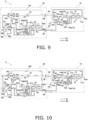
- Fig. 10 is a schematic configuration diagram illustrating a flow of the refrigerant during a heating operation.
- Fig. 11 is a schematic configuration diagram illustrating a flow of the refrigerant during a cooling operation. In Figs. 10 and 11 , the flow of the refrigerant is indicated by arrows.
- the control unit 50 controls the first control valves Vu6 and Vh6 and the second control valves Vu7 and Vh7 in addition to the control of the devices described in the first embodiment. Specifically, the control unit 50 opens the first control valve Vu6 and the second control valve Vh7, and closes the second control valve Vu7 and the first control valve Vh6.
- the refrigerant flows through the refrigerant circuit 100 as described below.
- the refrigerant that flows into the utilization-side branching section 13 is restricted from flowing to the inlet of the third check valve Vu3 while passing through the fourth check valve Vu4.
- the flow of the refrigerant that passes through the fourth check valve Vu4 is restricted by the second control valve Vu7, so that the refrigerant passes through the first control valve Vu6, and flows into the first flow path 14a of the utilization-side inflow section 14. Since the subsequent flow of the refrigerant until the refrigerant passes through the expansion mechanism 27 of the heat source unit 20 is the same as that in the first embodiment, description thereof will be omitted.
- the refrigerant that passes through the expansion mechanism 27 and flows into the heat-source-side branching section 23 is restricted from flowing to the inlet of the first check valve Vh1 while passing through the second check valve Vh2.
- the flow of the refrigerant that passes through the second check valve Vh2 is restricted by the first control valve Vh6, so that the refrigerant passes through the second control valve Vh7, and flows into the second flow path 24b of the heat-source-side inflow section 24. Since the subsequent flow of the refrigerant is the same as that in the first embodiment, description thereof will be omitted.
- the refrigerant that flows into the utilization unit 10 flows into the outlet of the first check valve Vu1 and the inlet of the second check valve Vu2 of the utilization-side branching section 13.
- the refrigerant that flows into the utilization-side branching section 13 is restricted from flowing into the inlet of the first check valve Vu1 while passing through the second check valve Vu2.
- the flow of the refrigerant that passes through the second check valve Vu2 is restricted by the first control valve Vu6, so that the refrigerant passes through the second control valve Vu7, and flows into the second flow path 14b of the utilization-side inflow section 14. Since the subsequent flow of the refrigerant is the same as that in the first embodiment, description thereof will be omitted.
- the refrigeration cycle apparatus 2 similarly to the refrigeration cycle apparatus 1, the refrigeration cycle apparatus 2 also suppresses the performance degradation of the apparatus caused by a significant pressure loss experienced by the gas refrigerant immediately before flowing into the heat exchangers 11 and 21 during the first operation. Accordingly, the refrigeration cycle apparatus 2 is capable of both ensuring the heat exchange efficiency in the heat exchangers 11 and 21 and suppressing the performance degradation of the apparatus caused by a pressure loss experienced by the refrigerant flowing into the heat exchangers 11 and 21, while using a zeotropic refrigerant mixture.
Landscapes
- Engineering & Computer Science (AREA)
- Physics & Mathematics (AREA)
- Mechanical Engineering (AREA)
- Thermal Sciences (AREA)
- General Engineering & Computer Science (AREA)
- Compression-Type Refrigeration Machines With Reversible Cycles (AREA)
- Heat-Exchange Devices With Radiators And Conduit Assemblies (AREA)
Abstract
Description
- The present disclosure relates to a refrigeration cycle apparatus.
- PTL 1 (
Japanese Unexamined Patent Application Publication No. 7-280375 PTL 1 discloses a refrigeration cycle apparatus that is provided with two refrigerant flow path switching devices in a refrigerant circuit, and includes a heat exchanger through which a refrigerant flows in a direction opposite to the flow of air in both cases, that is, during heating and cooling operations. - There is known a refrigerant circuit provided with a flow rate adjustment section using a distributor and a capillary tube at an end portion serving as an inflow side in a case where a heat exchanger functions as an evaporator, in order to ensure distribution performance for a gas-liquid two-phase refrigerant flowing into the heat exchanger. When this technique is applied to the refrigerant circuit of
PTL 1 in which the flow direction of the refrigerant passing through the heat exchanger is always the same, a gas refrigerant needs to pass through the distributor and the flow rate adjustment section in a case where the heat exchanger functions as a radiator. As a result, a pressure loss experienced by the gas refrigerant flowing into the heat exchanger increases compared to that in the related art, and thus the performance of the refrigeration cycle apparatus degrades, causing a problem. - The present disclosure provides a refrigeration cycle apparatus that uses a zeotropic refrigerant mixture and is capable of both ensuring the heat exchange efficiency in a heat exchanger and suppressing the performance degradation of the apparatus caused by a pressure loss experienced by the refrigerant flowing into the heat exchanger.
- A refrigeration cycle apparatus according to a first aspect uses a zeotropic refrigerant mixture as a refrigerant. The refrigeration cycle apparatus includes a refrigerant circuit and a control unit. The refrigerant circuit includes a heat exchanger that causes heat exchange between air and a refrigerant. The control unit performs a first operation that causes the heat exchanger to function as a radiator for the refrigerant and a second operation that causes the heat exchanger to function as an evaporator for the refrigerant. The refrigerant flows inside the heat exchanger in a direction opposite to a flow of the air during the first operation and the second operation.
- The refrigerant circuit includes an inflow section through which the refrigerant immediately before flowing into the heat exchanger passes. A pressure loss experienced by the refrigerant passing through the inflow section during the first operation is smaller than a pressure loss experienced by the refrigerant passing through the inflow section during the second operation.
- In the refrigeration cycle apparatus, the refrigerant flows inside the heat exchanger in a direction opposite to the flow of the air during heating and cooling operations. As a result, the heat exchange efficiency in the heat exchanger is ensured even in the refrigerant circuit using a zeotropic refrigerant mixture. Furthermore, in the refrigeration cycle apparatus, the pressure loss experienced by a gas refrigerant passing through the inflow section during the first operation is smaller than the pressure loss experienced by a gas-liquid two-phase refrigerant passing through the inflow section during the second operation. Therefore, the refrigeration cycle apparatus suppresses the performance degradation of the apparatus caused by a significant pressure loss experienced by the gas refrigerant immediately before flowing into the heat exchanger during the first operation. Accordingly, the refrigeration cycle apparatus is capable of both ensuring the heat exchange efficiency in the heat exchanger and suppressing the performance degradation of the apparatus caused by a pressure loss experienced by the refrigerant flowing into the heat exchanger, while using a zeotropic refrigerant mixture.
- A refrigeration cycle apparatus according to a second aspect is the refrigeration cycle apparatus according to the first aspect, in which the inflow section includes a first flow path and a second flow path. A pressure loss experienced by the refrigerant passing through the first flow path is smaller than a pressure loss experienced by the refrigerant passing through the second flow path. The refrigerant passes through the first flow path and flows into the heat exchanger during the first operation, and passes through the second flow path and flows into the heat exchanger during the second operation.
- The refrigeration cycle apparatus branches the refrigerant immediately before flowing into the heat exchanger into either the first flow path or the second flow path to change the pressure loss experienced by the refrigerant.
- A refrigeration cycle apparatus according to a third aspect is the refrigeration cycle apparatus according to the second aspect, in which a first refrigerant pipe included in the first flow path has a flow path area larger than a flow path area of a second refrigerant pipe included in the second flow path.
- In the refrigeration cycle apparatus, since the flow path area of the first refrigerant pipe is larger than the flow path area of the second refrigerant pipe, the pressure loss experienced by the refrigerant passing through the first flow path is smaller than the pressure loss experienced by the refrigerant passing through the second flow path.
- A refrigeration cycle apparatus according to a fourth aspect is the refrigeration cycle apparatus according to either the second aspect or the third aspect, in which the refrigerant circuit includes a branching section that switches a flow path of the refrigerant to either the first flow path or the second flow path.
- A refrigeration cycle apparatus according to a fifth aspect is the refrigeration cycle apparatus according to the fourth aspect, in which the first flow path includes a fifth check valve provided at a refrigerant pipe on a downstream side.
- In the refrigeration cycle apparatus, the fifth check valve suppresses the refrigerant from backflowing from the second flow path to the first flow path.
- A refrigeration cycle apparatus according to a sixth aspect is the refrigeration cycle apparatus according to the fourth aspect, in which the first flow path includes a control valve provided at a refrigerant pipe on a downstream side.
- In the refrigeration cycle apparatus, the control valve suppresses the refrigerant from backflowing from the second flow path to the first flow path.
-
-
Fig. 1 is a schematic configuration diagram of arefrigeration cycle apparatus 1. -
Fig. 2 is a block diagram of acontrol unit 50. -
Fig. 3 is a schematic configuration diagram of a utilization-side heat exchanger 11. -
Fig. 4 is a schematic configuration diagram of a heat-source-side heat exchanger 21. -
Fig. 5 is a schematic configuration diagram illustrating a flow of a refrigerant during a heating operation. -
Fig. 6 is a schematic configuration diagram illustrating a flow of the refrigerant during a cooling operation. -
Fig. 7 is a schematic configuration diagram of arefrigeration cycle apparatus 1a according to a modification A. -
Fig. 8 is a schematic configuration diagram of arefrigeration cycle apparatus 1b according to a modification B. -
Fig. 9 is a schematic configuration diagram of arefrigeration cycle apparatus 2. -
Fig. 10 is a schematic configuration diagram illustrating a flow of the refrigerant during a heating operation. -
Fig. 11 is a schematic configuration diagram illustrating a flow of the refrigerant during a cooling operation. - A
refrigeration cycle apparatus 1 is an apparatus that utilizes a vapor compression refrigeration cycle. Therefrigeration cycle apparatus 1 is an air-conditioning apparatus that performs a cooling operation that cools air in an air-conditioning target space (not illustrated) and heating that heats the air in the air-conditioning target space. Therefrigeration cycle apparatus 1 mainly includes oneutilization unit 10, oneheat source unit 20, a liquidrefrigerant connection pipe 30 and a gasrefrigerant connection pipe 40, and acontrol unit 50.Fig. 1 is a schematic configuration diagram of therefrigeration cycle apparatus 1.Fig. 2 is a block diagram of thecontrol unit 50. - Although details will be described later, the liquid
refrigerant connection pipe 30 and the gasrefrigerant connection pipe 40 are pipes that connect theutilization unit 10 and theheat source unit 20 to each other, and constitute arefrigerant circuit 100 together with the respective devices included in theheat source unit 20 and theutilization unit 10. The respective devices included in theheat source unit 20 and theutilization unit 10 are connected to each other usingfirst refrigerant pipes 61 orsecond refrigerant pipes 62. Thesecond refrigerant pipes 62 are formed to have flow path areas larger than those of thefirst refrigerant pipes 61. - The
refrigerant circuit 100 is filled with a zeotropic refrigerant mixture, which is a mixture of two or more types of zeotropic refrigerants. In the present embodiment, although not limited thereto, R454C is used as the refrigerant. - Note that the
refrigeration cycle apparatus 1 of the present embodiment includes oneutilization unit 10, but the number ofutilization units 10 is not limited to one. For example, therefrigeration cycle apparatus 1 may include a plurality ofutilization units 10. Furthermore, therefrigeration cycle apparatus 1 of the present embodiment includes oneheat source unit 20, but the number ofheat source units 20 is not limited to one. For example, therefrigeration cycle apparatus 1 may include a plurality ofheat source units 20. Moreover, therefrigeration cycle apparatus 1 may be an integrated apparatus in which theheat source unit 20 and theutilization unit 10 are assembled in a single housing, for example. - The
utilization unit 10 cools or heats air Ai in the air-conditioning target space. Theutilization unit 10 includes a utilization-side heat exchanger 11, a utilization-side fan 12, a utilization-side branching section 13, a utilization-side inflow section 14, and a utilization-side second header Hu2. In theutilization unit 10, the heating operation is an example of a first operation, and the cooling operation is an example of a second operation. - The utilization-
side heat exchanger 11 causes heat exchange between a refrigerant flowing inside the utilization-side heat exchanger 11 and the air Ai. The utilization-side heat exchanger 11 functions as a radiator during the heating operation, and functions as an evaporator during the cooling operation.Fig. 3 is a schematic configuration diagram of the utilization-side heat exchanger 11. InFig. 3 , directions in which the refrigerant flows are indicated by open arrows. Furthermore, a direction in which the air Ai supplied by the utilization-side fan 12 flows is indicated by a hatched arrow. In addition, a horizontal direction, a vertical direction, and respective directions such as up, down, windward, and leeward, referred to in the following description, correspond to directions indicated by arrows illustrated inFig. 3 . - The utilization-
side heat exchanger 11 is a fin-and-tube heat exchanger including a plurality of tubular heat transfer tubes 11hp, a plurality offins 11f, a plurality of first connecting tubes 11ca, and second connecting tubes 11cb. The heat transfer tubes 11hp are disposed so as to penetrate the plurality offins 11f and extend along a first direction (in the present embodiment, the horizontal direction). The plurality offins 11f are disposed in parallel to each other at predetermined intervals along the first direction. - The utilization-
side heat exchanger 11 includes three paths 11pa, 11pb, and 11pc. The paths 11pa, 11pb, and 11pc have an identical shape. The paths 11pa, 11pb, and 11pc each include a plurality of the heat transfer tubes 11hp, a plurality of the first connecting tubes 11ca, and the second connecting tube 11cb. The paths 11pa, 11pb, and 11pc each have an inlet 11i and an outlet 11o. The paths 11pa, 11pb, and 11pc are disposed along the first direction. - The paths 11pa, 11pb, and 11pc each include a heat transfer tube group Ru1 and a heat transfer tube group Ru2 in each of which a plurality of the heat transfer tubes 11hp are arranged in parallel to each other along a second direction (in the present embodiment, the vertical direction). In the present embodiment, the heat transfer tube groups Ru1 and Ru2 each include four heat transfer tubes 11hp. In other words, the paths 11pa, 11pb, and 11pc are each formed such that the heat transfer tubes 11hp disposed in four stages in the second direction are arranged in two rows in the first direction.
- The heat transfer tube groups Ru1 and Ru2 are disposed such that a plane including center axes of a plurality of the heat transfer tubes 11hp included in the heat transfer tube group Ru1 and a plane including center axes of a plurality of the heat transfer tubes 11hp included in the heat transfer tube group Ru2 are parallel to each other at a predetermined interval. Furthermore, the heat transfer tube groups Ru1 and Ru2 are disposed such that the planes including the center axes of the plurality of heat transfer tubes 11hp included in the heat transfer tube groups Ru1 and Ru2 are orthogonal to the direction in which the air Ai supplied by the utilization-
side fan 12 flows (in the present embodiment, the horizontal direction). The heat transfer tube group Ru1 is disposed on the windward side of the heat transfer tube group Ru2 in the direction in which the air Ai supplied by the utilization-side fan 12 flows. - The inlet 11i is an opening of an end portion of the heat transfer tube 11hp disposed at the uppermost position in the heat transfer tube group Ru2. The inlet 11i is connected to the utilization-
side inflow section 14. - The outlet 11o is an opening of an end portion of the heat transfer tube 11hp disposed at the lowermost position in the heat transfer tube group Ru1. The outlet 11o is connected to the utilization-side second header Hu2 via a first
refrigerant pipe 61. - Each first connecting tube 11ca is provided at an end portion of the heat transfer tube 11hp so that the refrigerant flowing to the end portion of the heat transfer tube 11hp can flow into an adjacent heat transfer tube 11hp of another stage along the second direction.
- The second connecting tube 11cb communicates the adjacent heat transfer tube groups Ru1 and Ru2 to each other. Specifically, the second connecting tube 11cb is provided so as to communicate an end portion of the heat transfer tube 11hp disposed at the lowermost position in the heat transfer tube group Ru2 and an end portion of the heat transfer tube 11hp disposed at the uppermost position in the heat transfer tube group Ru1 to each other.
- Note that the number of heat transfer tube groups Ru1 and Ru2, the number of paths 11pa, 11pb, and 11pc, the number of heat transfer tubes 11hp, and the like described above are examples, and the present embodiment is not limited thereto.
- The utilization-
side fan 12 is a fan that supplies the air Ai to the utilization-side heat exchanger 11. The utilization-side fan 12 is driven by a fan motor 12m (seeFig. 2 ). Thecontrol unit 50 controls the number of rotations of the fan motor 12m to control an amount of the air Ai supplied to the utilization-side heat exchanger 11. - The utilization-
side branching section 13 switches the flow path of the refrigerant that flows out of theheat source unit 20 and the flow path of the refrigerant that flows out of the utilization-side heat exchanger 11 between the heating operation and the cooling operation. The utilization-side branching section 13 is connected to the liquidrefrigerant connection pipe 30, the gasrefrigerant connection pipe 40, the utilization-side inflow section 14, and the utilization-side second header Hu2. - The utilization-
side branching section 13 includes a first check valve Vu1, a second check valve Vu2, a third check valve Vu3, and a fourth check valve Vu4. The first check valve Vu1, the second check valve Vu2, the third check valve Vu3, and the fourth check valve Vu4 each have an inlet and an outlet. The first check valve Vu1, the second check valve Vu2, the third check valve Vu3, and the fourth check valve Vu4 each allow the refrigerant to flow from the inlet to the outlet (in a direction indicated by each arrow in the drawing), and each restrict the refrigerant from flowing in a direction opposite to the direction indicated by the arrow. - The outlet of the first check valve Vu1 is connected to the inlet of the second check valve Vu2. The outlet of the third check valve Vu3 is connected to the inlet of the fourth check valve Vu4.
- The inlet of the first check valve Vu1 and the inlet of the third check valve Vu3 are connected to the utilization-side second header Hu2 via a second
refrigerant pipe 62. - The outlet of the first check valve Vu1 and the inlet of the second check valve Vu2 are connected to the liquid
refrigerant connection pipe 30 via a firstrefrigerant pipe 61. The outlet of the third check valve Vu3 and the inlet of the fourth check valve Vu4 are connected to the gasrefrigerant connection pipe 40 via a secondrefrigerant pipe 62. - The outlet of the second check valve Vu2 is connected to a
second flow path 14b (described later) of the utilization-side inflow section 14 via a firstrefrigerant pipe 61. The outlet of the fourth check valve Vu4 is connected to afirst flow path 14a (described later) of the utilization-side inflow section 14 via a secondrefrigerant pipe 62. - The utilization-
side inflow section 14 is a flow path through which the refrigerant immediately before flowing into the utilization-side heat exchanger 11 passes. The utilization-side inflow section 14 includes thefirst flow path 14a and thesecond flow path 14b. The utilization-side inflow section 14 is configured such that a pressure loss experienced by the refrigerant passing through thefirst flow path 14a is smaller than a pressure loss experienced by the refrigerant passing through thesecond flow path 14b. - The
first flow path 14a is a flow path through which the refrigerant passes during an operation that causes the utilization-side heat exchanger 11 to function as a radiator for the refrigerant (specifically, the heating operation). The refrigerant that flows into thefirst flow path 14a is distributed to the respective paths 11pa, 11pb, and 11pc by thefirst flow path 14a. Thefirst flow path 14a includes a utilization-side first header Hu1 and a plurality of fifth check valves Vu5. - The utilization-side first header Hu1 is a tubular member through which the refrigerant flows. The utilization-side first header Hu1 is connected to the utilization-side branching section 13 (specifically, the outlet of the fourth check valve Vu4) via the second
refrigerant pipe 62, and is connected to inlets of the fifth check valves Vu5 via secondrefrigerant pipes 62. - The fifth check valves Vu5 each allow the refrigerant to flow from the inlet to an outlet (in a direction indicated by each arrow in the drawing), and each restrict the refrigerant from flowing in a direction opposite to the direction indicated by the arrow. The inlets of the fifth check valves Vu5 are connected to the utilization-side first header Hu1 via the second
refrigerant pipes 62. The fifth check valves Vu5 suppress backflow of the refrigerant that comes from the utilization-side first header Hu1. The outlets of the fifth check valves Vu5 are connected to the respective inlets 11i of the paths 11pa, 11pb, and 11pc via secondrefrigerant pipes 62. - In the present embodiment, the
first flow path 14a includes three fifth check valves Vu5, and the respective three fifth check valves Vu5 are connected to the utilization-side first header Hu1 via individual secondrefrigerant pipes 62. The number of fifth check valves Vu5 included in thefirst flow path 14a is not limited to three, and may be two, four, or more, for example. - The
second flow path 14b is a flow path through which the refrigerant passes during an operation that causes the utilization-side heat exchanger 11 to function as an evaporator for the refrigerant (specifically, the cooling operation). The refrigerant that flows into thesecond flow path 14b is distributed to the respective paths 11pa, 11pb, and 11pc by thesecond flow path 14b. Thesecond flow path 14b includes a distributor Du and three flow rate adjustment sections Cu. - The distributor Du is a member that distributes the refrigerant that flows out of the utilization-
side branching section 13. The distributor Du is connected to the utilization-side branching section 13 (specifically, the second check valve Vu2) via the firstrefrigerant pipe 61, and is connected to inlets of the flow rate adjustment sections Cu via firstrefrigerant pipes 61. - The flow rate adjustment sections Cu are connected to the respective paths 11pa, 11pb, and 11pc of the utilization-
side heat exchanger 11, and adjust flow rates of the refrigerant flowing into the respective paths 11pa, 11pb, and 11pc. In the present embodiment, the flow rate adjustment sections Cu are narrow tubes (capillary tubes) each having an inlet and an outlet. The outlets of the flow rate adjustment sections Cu are connected to the respective inlets 11i of the paths 11pa, 11pb, and 11pc. In order to adjust the flow rate of the refrigerant passing through the inside of the flow rate adjustment section Cu, the flow rate adjustment section Cu is formed to have a flow path area smaller than those of the firstrefrigerant pipe 61 and the secondrefrigerant pipe 62. Therefore, a pressure loss experienced by the refrigerant when the refrigerant passes through the flow rate adjustment section Cu is larger than a pressure loss that the refrigerant receives when the refrigerant passes through the firstrefrigerant pipe 61 and the secondrefrigerant pipe 62. In order to adjust the flow rate of the refrigerant flowing into the respective paths 11pa, 11pb, and 11pc, the lengths and the flow path areas of the three flow rate adjustment sections Cu may be different from each other. - In this manner, the
first flow path 14a includes the utilization-side first header Hu1 and the fifth check valves Vu5 connected via the secondrefrigerant pipes 62, whereas thesecond flow path 14b includes the flow rate adjustment sections Cu in each of which the pressure loss experienced by the refrigerant passing through the flow rate adjustment section Cu is larger than that of the secondrefrigerant pipe 62. - Accordingly, in the utilization-
side inflow section 14, the pressure loss experienced by the refrigerant passing through thefirst flow path 14a is smaller than the pressure loss experienced by the refrigerant passing through thesecond flow path 14b. - The utilization-side second header Hu2 is a tubular member through which the refrigerant flows. The utilization-side second header Hu2 is connected to the outlets 11o of the utilization-
side heat exchanger 11 via a plurality of the firstrefrigerant pipes 61, and is connected to the utilization-side branching section 13 (specifically, the inlet of the first check valve Vu1 and the inlet of the third check valve Vu3) via the secondrefrigerant pipe 62. - The refrigerant that flows out of the utilization-
side inflow section 14 flows into the uppermost heat transfer tubes 11hp in the heat transfer tube groups Ru2 from the respective inlets 11i of the paths 11pa, 11pb, and 11pc. The refrigerant that flows into the heat transfer tube group Ru2 alternately passes through the heat transfer tube 11hp and the first connecting tube 11ca and moves downward while meandering through the heat transfer tube group Ru2. The refrigerant that flows into the lowermost heat transfer tube 11hp in the heat transfer tube group Ru2 passes through the second connecting tube 11cb, and flows into the uppermost heat transfer tube 11hp in the heat transfer tube group Ru1. The refrigerant that flows into the heat transfer tube group Ru1 also moves downward while meandering through the heat transfer tube group Ru1, passes through the outlet 11o, and flows out to the utilization-side second header Hu2. - In this manner, in the utilization-
side heat exchanger 11, the refrigerant flowing through each of the paths 11pa, 11pb, and 11pc flows inside the utilization-side heat exchanger 11 in the order from the heat transfer tube group Ru2 to the heat transfer tube group Ru1, in a direction opposite to the flow of the air Ai supplied by the utilization-side fan 12. - The
heat source unit 20 is disposed outside the air-conditioning target space. Theheat source unit 20 includes a heat-source-side heat exchanger 21, a heat-source-side fan 22, a heat-source-side branching section 23, a heat-source-side inflow section 24, a heat-source-side second header Hh2, a flowdirection switching mechanism 25, acompressor 26, anexpansion mechanism 27, a first shut-offvalve 28, and a second shut-offvalve 29. In theheat source unit 20, the cooling operation is an example of the first operation, and the heating operation is an example of the second operation. - The heat-source-
side heat exchanger 21 causes heat exchange between the refrigerant flowing inside the heat-source-side heat exchanger 21 and air Ao outside the air-conditioning target space. The heat-source-side heat exchanger 21 functions as a radiator during the cooling operation, and functions as an evaporator during the heating operation.Fig. 4 is a schematic configuration diagram of the heat-source-side heat exchanger 21. InFig. 4 , directions in which the refrigerant flows are indicated by open arrows. Furthermore, a direction in which the air Ao supplied by the heat-source-side fan 22 flows is indicated by a hatched arrow. In addition, the horizontal direction, the vertical direction, and respective directions such as up, down, windward, and leeward, referred to in the following description, correspond to directions indicated by arrows illustrated inFig. 4 . - The heat-source-
side heat exchanger 21 is a fin-and-tube heat exchanger including a plurality of tubular heat transfer tubes 21hp, a plurality offins 21f, a plurality of first connecting tubes 21ca, and second connecting tubes 21cb. The heat transfer tubes 21hp are disposed so as to penetrate the plurality offins 21f and extend along the first direction. The plurality offins 21f are disposed in parallel to each other at predetermined intervals along the first direction. - The heat-source-
side heat exchanger 21 includes three paths 21pa, 21pb, and 21pc. The three paths 21pa, 21pb, and 21pc each have an identical shape. The three paths 21pa, 21pb, and 21pc each have an individual refrigerant flow path, including a plurality of the heat transfer tubes 21hp, a plurality of the first connecting tubes 21ca, and the second connecting tube 21cb. The paths 21pa, 21pb, and 21pc each have an inlet 21i and an outlet 21o. The three paths 21pa, 21pb, and 21pc are arranged along the first direction. - The paths 21pa, 21pb, and 21pc each include a heat transfer tube group Rh1 and a heat transfer tube group Rh2 in each of which a plurality of the heat transfer tubes 21hp are arranged in parallel to each other along the second direction. In the present embodiment, the heat transfer tube groups Rh1 and Rh2 each include four heat transfer tubes 21hp. In other words, the paths 21pa, 21pb, and 21pc are each formed such that the heat transfer tubes 21hp disposed in four stages in the second direction are arranged in two rows in the first direction.
- The heat transfer tube groups Rh1 and Rh2 are disposed such that a plane including center axes of a plurality of the heat transfer tubes 21hp included in the heat transfer tube group Rh1 and a plane including center axes of a plurality of the heat transfer tubes 21hp included in the heat transfer tube group Rh2 are parallel to each other at a predetermined interval. Furthermore, the heat transfer tube groups Ru1 and Ru2 are disposed such that the planes including the center axes of the plurality of heat transfer tubes 21hp included in the heat transfer tube groups Ru1 and Ru2 are orthogonal to the direction in which the air Ao supplied by the heat-source-
side fan 22 flows (in the present embodiment, the horizontal direction). The heat transfer tube group Rh1 is disposed on the windward side of the heat transfer tube group Rh2 in the direction in which the air Ao supplied by the heat-source-side fan 22 flows. - The inlet 21i is an opening of an end portion of the heat transfer tube 21hp disposed at the uppermost position in the heat transfer tube group Rh2. The inlet 21i is connected to the heat-source-
side inflow section 24. - The outlet 21o is an opening of an end portion of the heat transfer tube 21hp disposed at the lowermost position in the heat transfer tube group Rh1. The outlet 21o is connected to the heat-source-side second header Hh2 via a first
refrigerant pipe 61. - Each first connecting tube 21ca is provided at an end portion of the heat transfer tube 21hp so that the refrigerant flowing to the end portion of the heat transfer tube 21hp can flow into an adjacent heat transfer tube 21hp of another stage along the second direction.
- The second connecting tube 21cb communicates the adjacent heat transfer tube groups Rh1 and Rh2 to each other. Specifically, the second connecting tube 21u is provided so as to communicate an end portion of the heat transfer tube 21hp disposed at the lowermost position in the heat transfer tube group Rh2 and an end portion of the heat transfer tube 21hp disposed at the uppermost position in the heat transfer tube group Rh1 to each other.
- Note that the number of heat transfer tube groups Rh1 and Rh2, the number of paths 21pa, 21pb, and 21pc, the numbers of heat transfer tubes 21hp, and the like described above are examples, and the present embodiment is not limited thereto.
- The heat-source-
side fan 22 is a fan that supplies the air Ao (heat source air) to the heat-source-side heat exchanger 21. The heat-source-side fan 22 is driven by a fan motor 22m (seeFig. 2 ). Thecontrol unit 50 controls the number of rotations of the fan motor 22m to control an amount of the air Ao supplied to the heat-source-side heat exchanger 21. - The heat-source-
side branching section 23 switches the flow path of the refrigerant that flows out of theutilization unit 10 and the flow path of the refrigerant that flows out of the heat-source-side heat exchanger 21 between the heating operation and the cooling operation. The heat-source-side branching section 23 is connected to the liquidrefrigerant connection pipe 30, the gasrefrigerant connection pipe 40, the utilization-side inflow section 14, and the utilization-side second header Hu2. - The heat-source-
side branching section 23 includes a first check valve Vh1, a second check valve Vh2, a third check valve Vh3, and a fourth check valve Vh4. The first check valve Vh1, the second check valve Vh2, the third check valve Vh3, and the fourth check valve Vh4 each have an inlet and an outlet. The first check valve Vh1, the second check valve Vh2, the third check valve Vh3, and the fourth check valve Vh4 each allow the refrigerant to flow from the inlet to the outlet (in a direction indicated by each arrow in the drawing), and each restrict the refrigerant from flowing in a direction opposite to the direction indicated by the arrow. - The outlet of the first check valve Vh1 is connected to the inlet of the second check valve Vh2. The outlet of the third check valve Vh3 is connected to the inlet of the fourth check valve Vh4.
- The inlet of the first check valve Vh1 and the inlet of the third check valve Vh3 are connected to the heat-source-side second header Hh2 via a first
refrigerant pipe 61. - The outlet of the first check valve Vh1 and the inlet of the second check valve Vh2 are connected to the
expansion mechanism 27 via a firstrefrigerant pipe 61. The outlet of the third check valve Vh3 and the inlet of the fourth check valve Vh4 are connected to a third port P3 (described later) of the flowdirection switching mechanism 25 via a secondrefrigerant pipe 62. - The outlet of the second check valve Vh2 is connected to a
second flow path 24b (described later) of the heat-source-side inflow section 24 via a firstrefrigerant pipe 61. The outlet of the fourth check valve Vh4 is connected to afirst flow path 24a (described later) of the heat-source-side inflow section 24 via a secondrefrigerant pipe 62. - The heat-source-
side inflow section 24 is a flow path through which the refrigerant immediately before flowing into the heat-source-side heat exchanger 21 passes. The heat-source-side inflow section 24 includes thefirst flow path 24a and thesecond flow path 24b. The heat-source-side inflow section 24 is configured such that a pressure loss experienced by the refrigerant passing through thefirst flow path 24a is smaller than a pressure loss experienced by the refrigerant passing through thesecond flow path 24b. - The
first flow path 24a is a flow path through which the refrigerant passes during an operation that causes the heat-source-side heat exchanger 21 to function as a radiator for the refrigerant (specifically, the cooling operation). The refrigerant that flows into thefirst flow path 24a is distributed to the respective paths 21pa, 21pb, and 21pc by thefirst flow path 24a. Thefirst flow path 24a includes a heat-source-side first header Hh1 and a plurality of fifth check valves Vh5. - The heat-source-side first header Hh1 is a tubular member through which the refrigerant flows. The heat-source-side first header Hh1 is connected to the heat-source-side branching section 23 (specifically, the outlet of the fourth check valve Vh4) via the second
refrigerant pipe 62, and is connected to inlets of the fifth check valves Vh5 via secondrefrigerant pipes 62. - The fifth check valves Vh5 each allow the refrigerant to flow from the inlet to an outlet (in a direction indicated by each arrow in the drawing), and each restrict the refrigerant from flowing in a direction opposite to the direction indicated by the arrow. The inlets of the fifth check valves Vh5 are connected to the heat-source-side first header Hh1 via the second
refrigerant pipes 62. The fifth check valves Vh5 suppress backflow of the refrigerant that comes from the heat-source-side first header Hh1. The outlets of the fifth check valves Vh5 are connected to the respective inlets 21i of the paths 21pa, 21pb, and 21pc via secondrefrigerant pipes 62. - In the present embodiment, the
first flow path 24a includes three fifth check valves Vh5, and the respective three fifth check valves Vh5 are connected to the heat-source-side first header Hh1 via individual secondrefrigerant pipes 62. The number of fifth check valves Vh5 included in thefirst flow path 24a is not limited to three, and may be two, four, or more, for example. - The
second flow path 24b is a flow path through which the refrigerant passes during an operation that causes the heat-source-side heat exchanger 21 to function as an evaporator for the refrigerant (specifically, the heating operation). The refrigerant that flows into thesecond flow path 24b is distributed to the respective paths 21pa, 21pb, and 21pc by thesecond flow path 24b. Thesecond flow path 24b includes a distributor Dh and three flow rate adjustment sections Ch. - The distributor Dh is a member that distributes the refrigerant that flows out of the heat-source-
side branching section 23. The distributor Dh is connected to the heat-source-side branching section 23 (specifically, the second check valve Vh2) via the firstrefrigerant pipe 61, and is connected to inlets of the flow rate adjustment sections Ch via firstrefrigerant pipes 61. - The flow rate adjustment sections Ch are connected to the respective paths 21pa, 21pb, and 21pc of the heat-source-
side heat exchanger 21, and adjust flow rates of the refrigerant flowing into the respective paths 21pa, 21pb, and 21pc. In the present embodiment, the flow rate adjustment sections Ch are narrow tubes (capillary tubes) each having an inlet and an outlet. The outlets of the flow rate adjustment sections Ch are connected to the respective inlets 21i of the paths 21pa, 21pb, and 21pc. In order to adjust the flow rate of the refrigerant passing through the inside of the flow rate adjustment section Ch, the flow rate adjustment section Ch is formed to have a flow path area smaller than those of the firstrefrigerant pipe 61 and the secondrefrigerant pipe 62. Therefore, a pressure loss experienced by the refrigerant when the refrigerant passes through the flow rate adjustment section Ch is larger than a pressure loss that the refrigerant receives when the refrigerant passes through the firstrefrigerant pipe 61 and the secondrefrigerant pipe 62. In order to adjust the flow rate of the refrigerant flowing into the respective paths 21pa, 21pb, and 21pc, the lengths and the flow path areas of the three flow rate adjustment sections Ch may be different from each other. - In this manner, the
first flow path 24a includes the heat-source-side first header Hh1 and the fifth check valves Vh5 connected via the secondrefrigerant pipes 62, whereas thesecond flow path 24b includes the flow rate adjustment sections Cu in each of which the pressure loss experienced by the refrigerant passing through the flow rate adjustment section Cu is larger than that of the secondrefrigerant pipe 62. - Accordingly, in the heat-source-
side inflow section 24, the pressure loss experienced by the refrigerant passing through thefirst flow path 24a is smaller than the pressure loss experienced by the refrigerant passing through thesecond flow path 24b. - The heat-source-side second header Hh2 is a tubular member through which the refrigerant flows. The heat-source-side second header Hh2 is connected to the outlets 21o of the heat-source-
side heat exchanger 21 via a plurality of the firstrefrigerant pipes 61, and is connected to the heat-source-side branching section 23 (specifically, the inlet of the first check valve Vh1 and the inlet of the third check valve Vh3) via the firstrefrigerant pipe 61. - The flow
direction switching mechanism 25 switches the flow direction of the refrigerant in therefrigerant circuit 100. The flowdirection switching mechanism 25 is a four-way switching valve that switches between a first state and a second state. The flowdirection switching mechanism 25 includes a first port P1, a second port P2, the third port P3, and a fourth port P4. Thecontrol unit 50 switches the flowdirection switching mechanism 25 between the first state and the second state. - The first port P1 is connected to the gas
refrigerant connection pipe 40 via a secondrefrigerant pipe 62. The second port P2 is connected to adischarge pipe 26b (described later) of thecompressor 26 via a firstrefrigerant pipe 61. The third port P3 is connected to the heat-source-side branching section 23 (specifically, the outlet of the third check valve Vh3 and the inlet of the fourth check valve Vh4) via the secondrefrigerant pipe 62. The fourth port P4 is connected to asuction pipe 26a (described later) of thecompressor 26 via a secondrefrigerant pipe 62. - In the first state, the flow
direction switching mechanism 25 communicates the first port P1 and the second port P2 with each other, and communicates the third port P3 and the fourth port P4 with each other (see solid lines in the flowdirection switching mechanism 25 inFig. 1 ). In the second state, the flowdirection switching mechanism 25 communicates the first port P1 and the third port P3 with each other, and communicates the second port P2 and the fourth port P4 with each other (see broken lines in the flowdirection switching mechanism 25 inFig. 1 ). - Note that the flow
direction switching mechanism 25 is not limited to the four-way switching valve. For example, the flowdirection switching mechanism 25 may be configured by combining a plurality of control valves and refrigerant pipes so as to achieve switching of the flow direction of the refrigerant described above. - The
compressor 26 sucks a low-pressure refrigerant in the refrigeration cycle from thesuction pipe 26a, compresses the refrigerant by using a compression mechanism (not illustrated), and discharges the compressed refrigerant from thedischarge pipe 26b. The compression mechanism of thecompressor 26 is driven by a compression mechanism motor 26m (seeFig. 2 ). Thecontrol unit 50 controls the number of rotations of the compression mechanism motor 26m to control a capacity of thecompressor 26. - The
suction pipe 26a of thecompressor 26 is connected to the fourth port P4 of the flowdirection switching mechanism 25 via the secondrefrigerant pipe 62. - The
discharge pipe 26b of thecompressor 26 is connected to the second port P2 of the flowdirection switching mechanism 25 via the firstrefrigerant pipe 61. - The
expansion mechanism 27 adjusts the pressure and the flow rate of the refrigerant passing through theexpansion mechanism 27. In the present embodiment, theexpansion mechanism 27 is a variable-opening-degree electric expansion mechanism. Thecontrol unit 50 controls the opening degree of theexpansion mechanism 27. One end of theexpansion mechanism 27 is connected to the liquidrefrigerant connection pipe 30 via a firstrefrigerant pipe 61. The other end of theexpansion mechanism 27 is connected to the heat-source-side branching section 23 (specifically, the outlet of the first check valve Vh1 and the inlet of the second check valve Vh2) via the firstrefrigerant pipe 61. - Note that the
expansion mechanism 27 is not limited to the electric expansion mechanism, and may be a temperature sensing cylinder type expansion mechanism or a capillary tube, for example. Alternatively, instead of theheat source unit 20 including theexpansion mechanism 27, theutilization unit 10 may include an expansion mechanism similar to theexpansion mechanism 27. - The first shut-off
valve 28 and the second shut-offvalve 29 are valves, each of which shuts off the refrigerant pipe to interrupt the flow of the refrigerant. For example, the first shut-offvalve 28 and the second shut-offvalve 29 are manually operated valves, and are opened and closed by an operator during the installation or similar operations of therefrigeration cycle apparatus 1. - The first shut-off
valve 28 is provided in the firstrefrigerant pipe 61 that connects theexpansion mechanism 27 and the liquidrefrigerant connection pipe 30 to each other. - The second shut-off
valve 29 is provided in the secondrefrigerant pipe 62 that connects the flowdirection switching mechanism 25 and the gasrefrigerant connection pipe 40 to each other. - The refrigerant that flows out of the heat-source-
side inflow section 24 flows into the uppermost heat transfer tubes 21hp in the heat transfer tube groups Rh2 from the respective inlets 21i of the paths 21pa, 21pb, and 21pc. The refrigerant that flows into the heat transfer tube group Rh2 alternately passes through the heat transfer tube 21hp and the first connecting tube 21ca and moves downward while meandering through the heat transfer tube group Rh2. The refrigerant that flows into the lowermost heat transfer tube 21hp in the heat transfer tube group Rh2 passes through the second connecting tube 21cb, and flows into the lowermost heat transfer tube 21hp in the heat transfer tube group Rh1. The refrigerant that flows into the heat transfer tube group Rh1 also moves downward while meandering through the heat transfer tube group Rh1, thereafter, passes through the outlet 21o, and flows out to the heat-source-side second header Hh2. - In this manner, in the heat-source-
side heat exchanger 21, the refrigerant flowing through each of the paths 21pa, 21pb, and 21pc flows inside the heat-source-side heat exchanger 21 in the order from the heat transfer tube group Rh2 to the heat transfer tube group Rh1, in a direction opposite to the flow of the air Ao supplied by the heat-source-side fan 22. - The liquid
refrigerant connection pipe 30 and the gasrefrigerant connection pipe 40 are pipes that connect theutilization unit 10 and theheat source unit 20 to each other. More specifically, the liquidrefrigerant connection pipe 30 is connected to the outlet of the first check valve Vu1 and the inlet of the second check valve Vu2 via the firstrefrigerant pipe 61, and is connected to one end of theexpansion mechanism 27 via the firstrefrigerant pipe 61. The gasrefrigerant connection pipe 40 is connected to the outlet of the third check valve Vu3 and the inlet of the fourth check valve Vu4 via the secondrefrigerant pipe 62, and is connected to the first port P1 of the flowdirection switching mechanism 25 via the secondrefrigerant pipe 62. - The gas
refrigerant connection pipe 40 is formed to have a flow path area larger than that of the liquidrefrigerant connection pipe 30. - The liquid
refrigerant connection pipe 30 and the gasrefrigerant connection pipe 40 are pipes mounted at an installation site of therefrigeration cycle apparatus 1 during the installation of therefrigeration cycle apparatus 1, for example. - The
control unit 50 is electrically connected so as to be able to control the utilization-side fan 12, the heat-source-side fan 22, the flowdirection switching mechanism 25, thecompressor 26, and theexpansion mechanism 27. Although details will be described later, when therefrigeration cycle apparatus 1 performs the cooling operation and the heating operation, thecontrol unit 50 controls these devices. - The
control unit 50 is implemented by a computer. Thecontrol unit 50 includes a control arithmetic device and a storage device (both not illustrated). As the control arithmetic device, a processor such as a CPU or a GPU can be used. The control arithmetic device reads a program stored in the storage device and executes predetermined image processing or arithmetic processing in accordance with the program. Moreover, the control arithmetic device can write an arithmetic result in the storage device and read information stored in the storage device in accordance with the program. The storage device can be used as a database. - Actions of each part of the
refrigeration cycle apparatus 1 during heating and cooling operations will be described.Fig. 5 is a schematic configuration diagram illustrating a flow of the refrigerant during a heating operation.Fig. 6 is a schematic configuration diagram illustrating a flow of the refrigerant during a cooling operation. InFigs. 5 and 6 , the flow of the refrigerant is indicated by arrows. - In response to an instruction for causing the
refrigeration cycle apparatus 1 to perform a heating operation, thecontrol unit 50 sets the flowdirection switching mechanism 25 to the first state, starts operations of the utilization-side fan 12, the heat-source-side fan 22, and thecompressor 26, and controls the opening degree of theexpansion mechanism 27. When therefrigeration cycle apparatus 1 performs the heating operation, the refrigerant flows through therefrigerant circuit 100 as described below. - When the operation of the
compressor 26 starts, a low-pressure gas refrigerant in the refrigeration cycle is sucked into thecompressor 26 from thesuction pipe 26a. The refrigerant that is compressed by thecompressor 26 and becomes a high-pressure gas refrigerant in the refrigeration cycle flows into the flowdirection switching mechanism 25 from the second port P2. The refrigerant that flows into the flowdirection switching mechanism 25 flows out from the first port P1, and thereafter, flows into theutilization unit 10 by way of the gasrefrigerant connection pipe 40. The refrigerant that flows into theutilization unit 10 flows into the outlet of the third check valve Vu3 and the inlet of the fourth check valve Vu4 of the utilization-side branching section 13. The refrigerant that flows into the utilization-side branching section 13 is restricted from flowing to the inlet of the third check valve Vu3 while passing through the fourth check valve Vu4, and flows into thefirst flow path 14a of the utilization-side inflow section 14. The refrigerant that flows into thefirst flow path 14a flows into the utilization-side heat exchanger 11 from the inlets 11i by way of the utilization-side first header Hu1 and the fifth check valves Vu5. The refrigerant that flows into the utilization-side heat exchanger 11 releases heat by exchanging heat with the air Ai supplied by the utilization-side fan 12, and becomes a high-pressure liquid refrigerant. In other words, at this time, the utilization-side heat exchanger 11 functions as a radiator in therefrigerant circuit 100. The temperature of the air Ai supplied to the utilization-side heat exchanger 11 rises as the air Ai exchanges heat with the refrigerant that flows into the utilization-side heat exchanger 11, and thereafter, the air Ai is blown out of theutilization unit 10. After flowing out from the outlets 11o, the high-pressure liquid refrigerant that flows out of the utilization-side heat exchanger 11 flows into the inlet of the first check valve Vu1 of the utilization-side branching section 13 by way of the utilization-side second header Hu2. The refrigerant that passes through the first check valve Vu1 flows into theheat source unit 20 by way of the liquidrefrigerant connection pipe 30. - The refrigerant that flows into the
heat source unit 20 flows into the outlet of the first check valve Vh1 and the inlet of the second check valve Vh2 of the heat-source-side branching section 23 by way of theexpansion mechanism 27. The refrigerant is depressurized to a pressure close to the suction pressure of thecompressor 26 when passing through theexpansion mechanism 27, and becomes a refrigerant in a gas-liquid two-phase state. The refrigerant that flows into the heat-source-side branching section 23 is restricted from flowing to the inlet of the first check valve Vh1 while passing through the second check valve Vh2, and flows into thesecond flow path 24b of the heat-source-side inflow section 24. The refrigerant that flows into thesecond flow path 24b flows into the heat-source-side heat exchanger 21 from the inlets 21i by way of the distributor Dh and the flow rate adjustment sections Ch. The refrigerant that is in a low-pressure gas-liquid two-phase state and flows into the heat-source-side heat exchanger 21 evaporates by exchanging heat with the air Ao supplied by the heat-source-side fan 22, and becomes a low-pressure gas refrigerant. In other words, at this time, the heat-source-side heat exchanger 21 functions as an evaporator in therefrigerant circuit 100. After flowing out from the outlets 21o, the low-pressure gas refrigerant that flows out of the heat-source-side heat exchanger 21 flows into the inlet of the third check valve Vh3 of the heat-source-side branching section 23 by way of the heat-source-side second header Hh2. The refrigerant that passes through the third check valve Vh3 flows into the flowdirection switching mechanism 25 from the third port P3. The refrigerant that flows into the flowdirection switching mechanism 25 flows out from the fourth port P4, and thereafter, is sucked into thecompressor 26 from thesuction pipe 26a again. - In this manner, during the heating operation, the refrigerant passes through the
first flow path 14a immediately before flowing into the utilization-side heat exchanger 11, and passes through thesecond flow path 24b immediately before flowing into the heat-source-side heat exchanger 21. More specifically, during the heating operation, the gas refrigerant immediately before flowing into the utilization-side heat exchanger 11 that functions as a radiator is distributed to the respective paths 11pa, 11pb, and 11pc in thefirst flow path 14a in which the pressure loss experienced is smaller than that of thesecond flow path 14b. Furthermore, during the heating operation, the gas-liquid two-phase refrigerant immediately before flowing into the heat-source-side heat exchanger 21 that functions as an evaporator is distributed to the respective paths 21pa, 21pb, and 21pc in thesecond flow path 24b in which the pressure loss experienced is larger than that of thefirst flow path 24a. - In response to an instruction for causing the
refrigeration cycle apparatus 1 to perform a cooling operation, thecontrol unit 50 sets the flowdirection switching mechanism 25 to the second state, starts operations of the utilization-side fan 12, the heat-source-side fan 22, and thecompressor 26, and controls the opening degree of theexpansion mechanism 27. When therefrigeration cycle apparatus 1 performs the cooling operation, the refrigerant flows through therefrigerant circuit 100 as described below. - When the operation of the
compressor 26 starts, a low-pressure gas refrigerant in the refrigeration cycle is sucked into thecompressor 26 from thesuction pipe 26a. The refrigerant that is compressed by thecompressor 26 and becomes a high-pressure gas refrigerant in the refrigeration cycle flows into the flowdirection switching mechanism 25 from the second port P2. The refrigerant that flows into the flowdirection switching mechanism 25 flows out from the third port P3, and thereafter, flows into the outlet of the third check valve Vh3 and the inlet of the fourth check valve Vh4 of the heat-source-side branching section 23. The refrigerant that flows into the heat-source-side branching section 23 is restricted from flowing into the inlet of the third check valve Vh3 while passing through the fourth check valve Vh4, and flows into thefirst flow path 24a of the heat-source-side inflow section 24. The refrigerant that flows into thefirst flow path 24a flows into the heat-source-side heat exchanger 21 from the inlets 21i by way of the heat-source-side first header Hh1 and the fifth check valves Vh5. The refrigerant that flows into the heat-source-side heat exchanger 21 releases heat by exchanging heat with the air Ao supplied by the heat-source-side fan 22, and becomes a high-pressure liquid refrigerant. In other words, at this time, the heat-source-side heat exchanger 21 functions as a radiator in therefrigerant circuit 100. After flowing out from the outlets 21o, the high-pressure liquid refrigerant that flows out of the heat-source-side heat exchanger 21 flows into the inlet of the first check valve Vh1 of the heat-source-side branching section 23 by way of the heat-source-side second header Hh2. The refrigerant that passes through the first check valve Vu1 flows into theutilization unit 10 by way of theexpansion mechanism 27 and the liquidrefrigerant connection pipe 30. The refrigerant is depressurized to a pressure close to the suction pressure of thecompressor 26 when passing through theexpansion mechanism 27, and becomes a refrigerant in a gas-liquid two-phase state. - The refrigerant that flows into the
utilization unit 10 flows into the outlet of the first check valve Vu1 and the inlet of the second check valve Vu2 of the utilization-side branching section 13. The refrigerant that flows into the utilization-side branching section 13 is restricted from flowing into the inlet of the first check valve Vu1 while passing through the second check valve Vu2, and flows into thesecond flow path 14b of the utilization-side inflow section 14. The refrigerant that flows into thesecond flow path 14b flows into the utilization-side heat exchanger 11 from the inlets 11i by way of the distributor Du and the flow rate adjustment sections Cu. The refrigerant that is in a low-pressure gas-liquid two-phase state and flows into the utilization-side heat exchanger 11 evaporates by exchanging heat with the air Ai supplied by the utilization-side fan 12, and becomes a low-pressure gas refrigerant. In other words, at this time, the utilization-side heat exchanger 11 functions as an evaporator in therefrigerant circuit 100. The temperature of the air Ai supplied to the utilization-side heat exchanger 11 decreases as the air Ai exchanges heat with the refrigerant that flows into the utilization-side heat exchanger 11, and thereafter, the air Ai is blown out of theutilization unit 10. After flowing out from the outlets 11o, the low-pressure gas refrigerant that flows out of the utilization-side heat exchanger 11 flows into the inlet of the third check valve Vu3 of the utilization-side branching section 13 by way of the utilization-side second header Hu2. The refrigerant that passes through the third check valve Vu3 flows into theheat source unit 20 by way of the gasrefrigerant connection pipe 40. The refrigerant that flows into theheat source unit 20 flows into the flowdirection switching mechanism 25 from the first port P1. The refrigerant that flows into the flowdirection switching mechanism 25 flows out from the fourth port P4, and thereafter, is sucked into thecompressor 26 from thesuction pipe 26a again. - In this manner, during the cooling operation, the refrigerant passes through the
second flow path 24b immediately before flowing into the utilization-side heat exchanger 11, and passes through thefirst flow path 24a immediately before flowing into the heat-source-side heat exchanger 21. More specifically, during the cooling operation, the gas-liquid two-phase refrigerant immediately before flowing into the utilization-side heat exchanger 11 that functions as an evaporator is distributed to the respective paths 11pa, 11pb, and 11pc in thesecond flow path 14b in which the pressure loss experienced is larger than that of thefirst flow path 14a. Furthermore, during the cooling operation, the gas-liquid two-phase refrigerant immediately before flowing into the heat-source-side heat exchanger 21 that functions as a radiator is distributed to the respective paths 21pa, 21pb, and 21pc in thefirst flow path 14a in which the pressure loss experienced is smaller than that of thesecond flow path 24b. - (4-1) The
refrigeration cycle apparatus 1 uses a zeotropic refrigerant mixture as a refrigerant. Therefrigeration cycle apparatus 1 includes therefrigerant circuit 100 and thecontrol unit 50. Therefrigerant circuit 100 includesheat exchangers 11 and 21 (the utilization-side heat exchanger 11 and the heat-source-side heat exchanger 21) that cause heat exchange between the air Ai and the Ao, respectively, and the refrigerant. Thecontrol unit 50 performs a first operation that causes theheat exchangers heat exchangers heat exchangers - The
refrigerant circuit 100 includesinflow sections 14 and 24 (the utilization-side inflow section 14 and the heat-source-side inflow section 24) through which the refrigerant immediately before flowing into theheat exchangers inflow sections inflow sections - In the
refrigeration cycle apparatus 1, the refrigerant flows inside theheat exchangers heat exchangers refrigerant circuit 100 using a zeotropic refrigerant mixture. Furthermore, in therefrigeration cycle apparatus 1, the pressure losses experienced by the refrigerant (gas refrigerant) passing through theinflow sections inflow sections refrigeration cycle apparatus 1 suppresses the performance degradation of the apparatus caused by a significant pressure loss experienced by the gas refrigerant immediately before flowing into theheat exchangers refrigeration cycle apparatus 1 is capable of both ensuring the heat exchange efficiency in theheat exchangers heat exchangers - (4-2) The
inflow sections first flow paths second flow paths first flow paths second flow paths first flow paths heat exchangers second flow paths heat exchangers - The
refrigeration cycle apparatus 1 branches the refrigerant immediately before flowing into theheat exchangers first flow paths second flow paths - (4-3) The first
refrigerant pipes 61 included in thefirst flow paths refrigerant pipes 62 included in thesecond flow paths - In the
refrigeration cycle apparatus 1, since the flow path area of the firstrefrigerant pipe 61 is larger than the flow path area of the secondrefrigerant pipe 62, the pressure losses experienced by the refrigerant passing through thefirst flow paths second flow paths - (4-4) The
refrigerant circuit 100 includes branching sections (the utilization-side branching section 13 and the heat-source-side branching section 23) that switch the flow paths of the refrigerant to either thefirst flow paths second flow paths - (4-5) The
first flow paths refrigerant pipes 62 on the downstream side. - The fifth check valves Vu5 and Vh5 suppress the refrigerant from backflowing from the
second flow paths first flow paths -
Fig. 7 is a schematic configuration diagram of arefrigeration cycle apparatus 1a according to a modification A. Therefrigeration cycle apparatus 1a does not include the utilization-side branching section 13 and thefirst flow path 14a of the utilization-side inflow section 14. In therefrigeration cycle apparatus 1a, the utilization-side second header Hu2 is connected to the gasrefrigerant connection pipe 40. Furthermore, the distributor Du of thesecond flow path 14b is connected to the liquidrefrigerant connection pipe 30. - In the
refrigeration cycle apparatus 1a, during the heating operation, the refrigerant that passes through the gasrefrigerant connection pipe 40 and flows into theutilization unit 10 passes through the utilization-side second header Hu2, and flows into the utilization-side heat exchanger 11. The refrigerant that flows into the utilization-side heat exchanger 11 releases heat by exchanging heat with the air Ai, passes through thesecond flow path 14b and the liquidrefrigerant connection pipe 30, and then flows into theheat source unit 20. Furthermore, during the cooling operation, the refrigerant that passes through the liquidrefrigerant connection pipe 30 and flows into theutilization unit 10 passes through thesecond flow path 14b, and flows into the utilization-side heat exchanger 11. The refrigerant that flows into the utilization-side heat exchanger 11 evaporates by exchanging heat with the air Ai, passes through the utilization-side second header Hu2 and the gasrefrigerant connection pipe 40, and then flows into theheat source unit 20. The flow of the refrigerant in other places is similar to that in therefrigeration cycle apparatus 1. Therefore, the description thereof will be omitted. - In the
refrigeration cycle apparatus 1a, the direction in which the refrigerant flows in the utilization-side heat exchanger 11 is switched to the opposite direction between the heating operation and the refrigerant operation. -
Fig. 8 is a schematic configuration diagram of arefrigeration cycle apparatus 1b according to a modification B. Therefrigeration cycle apparatus 1b does not include the heat-source-side branching section 23 and thefirst flow path 24a of the heat-source-side inflow section 24. In therefrigeration cycle apparatus 1b, the heat-source-side second header Hh2 is connected to the third port P3 of the flowdirection switching mechanism 25. Furthermore, the distributor Dh of thesecond flow path 24b is connected to the other end of theexpansion mechanism 27. - In the
refrigeration cycle apparatus 1b, during the heating operation, the refrigerant that passes through the liquidrefrigerant connection pipe 30 and flows into theheat source unit 20 passes through theexpansion mechanism 27 and thesecond flow path 24b, and flows into the heat-source-side heat exchanger 21. The refrigerant that flows into the heat-source-side heat exchanger 21 evaporates by exchanging heat with the air Ao, passes through the heat-source-side second header Hh2, and then flows into the third port P3 of the flowdirection switching mechanism 25. Furthermore, during the cooling operation, the refrigerant that flows out from the third port P3 of the flowdirection switching mechanism 25 passes through the heat-source-side second header Hh2, and flows into the heat-source-side heat exchanger 21. The refrigerant that flows into the heat-source-side heat exchanger 21 releases heat by exchanging heat with the air Ao, passes through thesecond flow path 24b, and then flows into theexpansion mechanism 27. The flow of the refrigerant in other places is similar to that in therefrigeration cycle apparatus 1. Therefore, the description thereof will be omitted. - In the
refrigeration cycle apparatus 1b, the direction in which the refrigerant flows in the heat-source-side heat exchanger 21 is switched to the opposite direction between the heating operation and the refrigerant operation. - As long as the refrigerant can flow inside the utilization-
side heat exchanger 11 in a direction opposite to the flow of the air Ai supplied by the utilization-side fan 12, the number, shape, arrangement, and the like of the heat transfer tubes 11hp andfins 11f included in the utilization-side heat exchanger 11 are not limited to modes described in the embodiment. Similarly, as long as the refrigerant can flow inside the heat-source-side heat exchanger 21 in a direction opposite to the flow of the air Ao supplied by the heat-source-side fan 22, the number, shape, arrangement, and the like of the heat transfer tubes 21hp andfins 21f included in the heat-source-side heat exchanger 21 are also not limited to modes described in the embodiment. - For example, the fifth check valves Vu5 and Vh5 may be control valves whose opening and closing are controlled by the
control unit 50. In this case, it is sufficient for thecontrol unit 50 to open the control valves during an operation in which the refrigerant passes through thefirst flow paths second flow paths control unit 50 to open the control valves included in thefirst flow path 14a and to close the control valves included in thefirst flow path 24a. Furthermore, during the cooling operation, it is sufficient for thecontrol unit 50 to close the control valves included in thefirst flow path 14a and to open the control valves included in thefirst flow path 24a. - According to the
refrigeration cycle apparatus 1 of the modification D, the control valves suppress the refrigerant from backflowing from thesecond flow paths first flow paths - The difference between the
refrigeration cycle apparatus 1 and arefrigeration cycle apparatus 2 is that therefrigeration cycle apparatus 2 includes a utilization-side branching section 13a instead of the utilization-side branching section 13, and a heat-source-side branching section 23a instead of the heat-source-side branching section 23. Hereinafter, the difference between therefrigeration cycle apparatus 1 and therefrigeration cycle apparatus 2 will be mainly described.Fig. 9 is a schematic configuration diagram of therefrigeration cycle apparatus 1. The same or corresponding components between therefrigeration cycle apparatus 1 and therefrigeration cycle apparatus 2 are denoted by the same reference numerals, and description thereof will be appropriately omitted. - The utilization-side branching section 13a further includes a first control valve Vu6 and a second control valve Vu7 in addition to the first check valve Vu1, the second check valve Vu2, the third check valve Vu3, and the fourth check valve Vu4. The
control unit 50 controls the respective opening degrees of the first control valve Vu6 and the second control valve Vu7. Furthermore, the outlets of the second check valve Vu2 and the fourth check valve Vu4 of the utilization-side branching section 13a are connected to one end of the first control valve Vu6 and one end of the second control valve Vu7 via a secondrefrigerant pipe 62. - The first control valve Vu6 is an electromagnetic valve whose opening and closing are controlled by the
control unit 50. The other end of the first control valve Vu6 is connected to the utilization-side first header Hu1 of thefirst flow path 14a included in the utilization-side inflow section 14 via a secondrefrigerant pipe 62. - The second control valve Vu7 is an electromagnetic valve whose opening and closing are controlled by the
control unit 50. The other end of the second control valve Vu7 is connected to the distributor Du of thesecond flow path 14b included in the utilization-side inflow section 14 via a firstrefrigerant pipe 61. - The heat-source-side branching section 23a further includes a first control valve Vh6 and a second control valve Vh7 in addition to the first check valve Vh1, the second check valve Vh2, the third check valve Vh3, and the fourth check valve Vh4. The
control unit 50 controls the respective opening degrees of the first control valve Vh6 and the second control valve Vh7. Furthermore, the outlets of the second check valve Vh2 and the fourth check valve Vh4 of the utilization-side branching section 13a are connected to one end of the first control valve Vh6 and one end of the second control valve Vh7 via a secondrefrigerant pipe 62. - The first control valve Vh6 is an electromagnetic valve whose opening and closing are controlled by the
control unit 50. The other end of the first control valve Vh6 is connected to the heat-source-side first header Hh1 of thefirst flow path 14a included in the heat-source-side inflow section 24 via a secondrefrigerant pipe 62. - The second control valve Vu7 is an electromagnetic valve whose opening and closing are controlled by the
control unit 50. The other end of the second control valve Vh7 is connected to the distributor Dh of thesecond flow path 14b included in the heat-source-side inflow section 24 via a firstrefrigerant pipe 61. - The
control unit 50 is electrically connected so as to be able to control the first control valves Vu6 and Vh6 and the second control valves Vu7 and Vh7 in addition to the utilization-side fan 12, the heat-source-side fan 22, the flowdirection switching mechanism 25, thecompressor 26, and theexpansion mechanism 27. - Actions of each part of the
refrigeration cycle apparatus 2 during heating and cooling operations will be described, with a focus on differences from those in therefrigeration cycle apparatus 1.Fig. 10 is a schematic configuration diagram illustrating a flow of the refrigerant during a heating operation.Fig. 11 is a schematic configuration diagram illustrating a flow of the refrigerant during a cooling operation. InFigs. 10 and11 , the flow of the refrigerant is indicated by arrows. - In response to an instruction for causing the
refrigeration cycle apparatus 2 to perform a heating operation, thecontrol unit 50 controls the first control valves Vu6 and Vh6 and the second control valves Vu7 and Vh7 in addition to the control of the devices described in the first embodiment. Specifically, thecontrol unit 50 opens the first control valve Vu6 and the second control valve Vh7, and closes the second control valve Vu7 and the first control valve Vh6. When therefrigeration cycle apparatus 2 performs the heating operation, the refrigerant flows through therefrigerant circuit 100 as described below. - When the operation of the
compressor 26 starts, a low-pressure gas refrigerant in the refrigeration cycle is sucked into thecompressor 26 from thesuction pipe 26a. The refrigerant that is compressed by thecompressor 26 and becomes a high-pressure gas refrigerant in the refrigeration cycle flows into the flowdirection switching mechanism 25 from the second port P2. The refrigerant that flows into the flowdirection switching mechanism 25 flows out from the first port P1, and thereafter, flows into theutilization unit 10 by way of the gasrefrigerant connection pipe 40. The refrigerant that flows into theutilization unit 10 flows into the outlet of the third check valve Vu3 and the inlet of the fourth check valve Vu4 of the utilization-side branching section 13. The refrigerant that flows into the utilization-side branching section 13 is restricted from flowing to the inlet of the third check valve Vu3 while passing through the fourth check valve Vu4. The flow of the refrigerant that passes through the fourth check valve Vu4 is restricted by the second control valve Vu7, so that the refrigerant passes through the first control valve Vu6, and flows into thefirst flow path 14a of the utilization-side inflow section 14. Since the subsequent flow of the refrigerant until the refrigerant passes through theexpansion mechanism 27 of theheat source unit 20 is the same as that in the first embodiment, description thereof will be omitted. - Thereafter, the refrigerant that passes through the
expansion mechanism 27 and flows into the heat-source-side branching section 23 is restricted from flowing to the inlet of the first check valve Vh1 while passing through the second check valve Vh2. The flow of the refrigerant that passes through the second check valve Vh2 is restricted by the first control valve Vh6, so that the refrigerant passes through the second control valve Vh7, and flows into thesecond flow path 24b of the heat-source-side inflow section 24. Since the subsequent flow of the refrigerant is the same as that in the first embodiment, description thereof will be omitted. - In response to an instruction for causing the
refrigeration cycle apparatus 2 to perform a cooling operation, thecontrol unit 50 controls the first control valves Vu6 and Vh6 and the second control valves Vu7 and Vh7 in addition to the control of the devices described in the first embodiment. Specifically, thecontrol unit 50 closes the first control valve Vu6 and the second control valve Vh7, and opens the second control valve Vu7 and the first control valve Vh6. When therefrigeration cycle apparatus 2 performs the heating operation, the refrigerant flows through therefrigerant circuit 100 as described below. - When the operation of the
compressor 26 starts, a low-pressure gas refrigerant in the refrigeration cycle is sucked into thecompressor 26 from thesuction pipe 26a. The refrigerant that is compressed by thecompressor 26 and becomes a high-pressure gas refrigerant in the refrigeration cycle flows into the flowdirection switching mechanism 25 from the second port P2. The refrigerant that flows into the flowdirection switching mechanism 25 flows out from the third port P3, and thereafter, flows into the outlet of the third check valve Vh3 and the inlet of the fourth check valve Vh4 of the heat-source-side branching section 23. The refrigerant that flows into the heat-source-side branching section 23 is restricted from flowing into the inlet of the third check valve Vh3 while passing through the fourth check valve Vh4. The flow of the refrigerant that passes through the fourth check valve Vh4 is restricted by the second control valve Vh7, so that the refrigerant passes through the first control valve Vh6, and flows into thefirst flow path 24a of the heat-source-side inflow section 24. Since the subsequent flow of the refrigerant until the refrigerant flows into theutilization unit 10 is the same as that in the first embodiment, description thereof will be omitted. - Thereafter, the refrigerant that flows into the
utilization unit 10 flows into the outlet of the first check valve Vu1 and the inlet of the second check valve Vu2 of the utilization-side branching section 13. The refrigerant that flows into the utilization-side branching section 13 is restricted from flowing into the inlet of the first check valve Vu1 while passing through the second check valve Vu2. The flow of the refrigerant that passes through the second check valve Vu2 is restricted by the first control valve Vu6, so that the refrigerant passes through the second control valve Vu7, and flows into thesecond flow path 14b of the utilization-side inflow section 14. Since the subsequent flow of the refrigerant is the same as that in the first embodiment, description thereof will be omitted. - As has been described above, similarly to the
refrigeration cycle apparatus 1, therefrigeration cycle apparatus 2 also suppresses the performance degradation of the apparatus caused by a significant pressure loss experienced by the gas refrigerant immediately before flowing into theheat exchangers refrigeration cycle apparatus 2 is capable of both ensuring the heat exchange efficiency in theheat exchangers heat exchangers - The embodiments of the present disclosure have been described heretofore, and it will be understood that a variety of modifications in mode and detail may be made without departing from the gist and scope of the present disclosure as set forth in claims.
-
- 1
- REFRIGERATION CYCLE APPARATUS
- 10
- UTILIZATION UNIT
- 11
- UTILIZATION-SIDE HEAT EXCHANGER
- 12
- UTILIZATION-SIDE FAN
- 13
- UTILIZATION-SIDE BRANCHING SECTION
- 14
- UTILIZATION-SIDE INFLOW SECTION
- 14a
- FIRST FLOW PATH
- Hu1
- UTILIZATION-SIDE FIRST HEADER
- Vu5
- FIFTH CHECK VALVE
- 14b
- SECOND FLOW PATH
- Du
- DISTRIBUTOR
- Cu
- FLOW RATE ADJUSTMENT SECTION
- Hu2
- UTILIZATION-SIDE SECOND HEADER
- 20
- HEAT SOURCE UNIT
- 21
- HEAT-SOURCE-SIDE HEAT EXCHANGER
- 22
- HEAT-SOURCE-SIDE FAN
- 23
- HEAT-SOURCE-SIDE BRANCHING SECTION
- 24
- HEAT-SOURCE-SIDE INFLOW SECTION
- 24a
- FIRST FLOW PATH
- Hh1
- UTILIZATION-SIDE FIRST HEADER
- Vh5
- FIFTH CHECK VALVE
- 24b
- SECOND FLOW PATH
- Dh
- DISTRIBUTOR
- Ch
- FLOW RATE ADJUSTMENT SECTION
- 25
- FLOW DIRECTION SWITCHING MECHANISM
- 26
- COMPRESSOR
- 27
- EXPANSION MECHANISM
- 28
- FIRST SHUT-OFF VALVE
- 29
- SECOND SHUT-OFF VALVE
- 30
- LIQUID REFRIGERANT CONNECTION PIPE
- 40
- GAS REFRIGERANT CONNECTION PIPE
- 50
- CONTROL UNIT
- 61
- FIRST REFRIGERANT PIPE
- 62
- SECOND REFRIGERANT PIPE
- 100
- REFRIGERANT CIRCUIT
- Ai
- AIR IN AIR-CONDITIONING TARGET SPACE
- Ao
- AIR OUTSIDE AIR-CONDITIONING TARGET SPACE
- PTL 1:
Japanese Unexamined Patent Application Publication No. 7-280375
Claims (6)
- A refrigeration cycle apparatus (1) using a zeotropic refrigerant mixture as a refrigerant, the apparatus comprising:a refrigerant circuit (100) including a heat exchanger (11, 21) that causes heat exchange between air (Ai, Ao) and the refrigerant; anda control unit (50) that performs a first operation that causes the heat exchanger to function as a radiator for the refrigerant and a second operation that causes the heat exchanger to function as an evaporator for the refrigerant, whereinthe refrigerantflows inside the heat exchanger in a direction opposite to a flow of the air during the first operation and the second operation,the refrigerant circuitincludes an inflow section (14, 24) through which the refrigerant immediately before flowing into the heat exchanger passes, anda pressure loss experienced by the refrigerant passing through the inflow section during the first operationis smaller than a pressure loss experienced by the refrigerant passing through the inflow section during the second operation.
- The refrigeration cycle apparatus according to claim 1, whereinthe inflow sectionincludes a first flow path (14a, 24a) and a second flow path (14b, 24b),a pressure loss experienced by the refrigerant passing through the first flow pathis smaller than a pressure loss experienced by the refrigerant passing through the second flow path, andthe refrigerantpasses through the first flow path and flows into the heat exchanger during the first operation, andpasses through the second flow path and flows into the heat exchanger during the second operation.
- The refrigeration cycle apparatus according to claim 2, whereina first refrigerant pipe (61) included in the first flow pathhas a flow path area larger than a flow path area of a second refrigerant pipe (62) included in the second flow path.
- The refrigeration cycle apparatus according to claim 2 or 3, whereinthe refrigerant circuitincludes a branching section (13, 23) that switches a flow path of the refrigerant to either the first flow path or the second flow path.
- The refrigeration cycle apparatus according to claim 4, whereinthe first flow pathincludes a check valve (Vu5, Vh5) provided at a refrigerant pipe on a downstream side.
- The refrigeration cycle apparatus according to claim 4, whereinthe first flow pathincludes a control valve provided at a refrigerant pipe on a downstream side.
Applications Claiming Priority (2)
| Application Number | Priority Date | Filing Date | Title |
|---|---|---|---|
| JP2022056448A JP7401800B2 (en) | 2022-03-30 | 2022-03-30 | Refrigeration cycle equipment |
| PCT/JP2023/011916 WO2023190202A1 (en) | 2022-03-30 | 2023-03-24 | Refrigeration cycle device |
Publications (2)
| Publication Number | Publication Date |
|---|---|
| EP4502500A1 true EP4502500A1 (en) | 2025-02-05 |
| EP4502500A4 EP4502500A4 (en) | 2025-07-16 |
Family
ID=88201452
Family Applications (1)
| Application Number | Title | Priority Date | Filing Date |
|---|---|---|---|
| EP23780212.9A Pending EP4502500A4 (en) | 2022-03-30 | 2023-03-24 | REFRIGERATING CYCLE DEVICE |
Country Status (3)
| Country | Link |
|---|---|
| EP (1) | EP4502500A4 (en) |
| JP (1) | JP7401800B2 (en) |
| WO (1) | WO2023190202A1 (en) |
Family Cites Families (5)
| Publication number | Priority date | Publication date | Assignee | Title |
|---|---|---|---|---|
| JPS6039868U (en) * | 1983-08-26 | 1985-03-20 | ダイキン工業株式会社 | heat pump refrigeration equipment |
| JPH07280375A (en) * | 1994-04-06 | 1995-10-27 | Hitachi Ltd | Air conditioner |
| JP2015141006A (en) * | 2014-01-30 | 2015-08-03 | パナソニック株式会社 | Air conditioner |
| JP2015158326A (en) * | 2014-02-25 | 2015-09-03 | パナソニック株式会社 | Refrigeration apparatus and air conditioner using the refrigeration apparatus |
| JP6798009B2 (en) * | 2017-04-11 | 2020-12-09 | 三菱電機株式会社 | Refrigeration cycle equipment |
-
2022
- 2022-03-30 JP JP2022056448A patent/JP7401800B2/en active Active
-
2023
- 2023-03-24 EP EP23780212.9A patent/EP4502500A4/en active Pending
- 2023-03-24 WO PCT/JP2023/011916 patent/WO2023190202A1/en not_active Ceased
Also Published As
| Publication number | Publication date |
|---|---|
| WO2023190202A1 (en) | 2023-10-05 |
| JP7401800B2 (en) | 2023-12-20 |
| EP4502500A4 (en) | 2025-07-16 |
| JP2023148435A (en) | 2023-10-13 |
Similar Documents
| Publication | Publication Date | Title |
|---|---|---|
| JP6644154B2 (en) | Air conditioner | |
| EP2495510B1 (en) | Heat pump | |
| AU2009239038B2 (en) | Refrigeration apparatus | |
| CN101086352B (en) | Air conditioner | |
| EP2341299A2 (en) | Multi-type air conditioner with defrosting device | |
| WO2018047330A1 (en) | Air conditioner | |
| US11499727B2 (en) | Air conditioning apparatus | |
| EP2728270A1 (en) | Outdoor machine of refrigeration device | |
| CN114867972B (en) | Air conditioning equipment | |
| US11578898B2 (en) | Air conditioning apparatus | |
| WO2023170743A1 (en) | Refrigeration cycle device | |
| WO2021014520A1 (en) | Air-conditioning device | |
| CN110382978B (en) | Heat Exchangers and Air Conditioners | |
| CN115349072B (en) | Air conditioning unit | |
| US11397015B2 (en) | Air conditioning apparatus | |
| EP4083558B1 (en) | Heat exchanger and refrigeration cycle device | |
| US20200309417A1 (en) | Air conditioning apparatus | |
| KR100677267B1 (en) | Distribution Unit of Cold and Cold Simultaneous Multi Air Conditioner | |
| EP4283221A1 (en) | Heat exchanger | |
| JP7401800B2 (en) | Refrigeration cycle equipment | |
| US12111082B2 (en) | Air conditioning apparatus | |
| KR101425043B1 (en) | Outdoor heat exchanger | |
| CN1323267C (en) | Multistage evaporation type air conditioner | |
| US12339076B2 (en) | Heat exchanger assembly and method for HVAC system | |
| EP4506629A1 (en) | Outdoor unit and air conditioner equipped with same |
Legal Events
| Date | Code | Title | Description |
|---|---|---|---|
| STAA | Information on the status of an ep patent application or granted ep patent |
Free format text: STATUS: THE INTERNATIONAL PUBLICATION HAS BEEN MADE |
|
| PUAI | Public reference made under article 153(3) epc to a published international application that has entered the european phase |
Free format text: ORIGINAL CODE: 0009012 |
|
| STAA | Information on the status of an ep patent application or granted ep patent |
Free format text: STATUS: REQUEST FOR EXAMINATION WAS MADE |
|
| 17P | Request for examination filed |
Effective date: 20241023 |
|
| AK | Designated contracting states |
Kind code of ref document: A1 Designated state(s): AL AT BE BG CH CY CZ DE DK EE ES FI FR GB GR HR HU IE IS IT LI LT LU LV MC ME MK MT NL NO PL PT RO RS SE SI SK SM TR |
|
| DAV | Request for validation of the european patent (deleted) | ||
| DAX | Request for extension of the european patent (deleted) | ||
| A4 | Supplementary search report drawn up and despatched |
Effective date: 20250616 |
|
| RIC1 | Information provided on ipc code assigned before grant |
Ipc: F25B 13/00 20060101AFI20250610BHEP Ipc: F25B 1/00 20060101ALI20250610BHEP Ipc: F25B 41/48 20210101ALI20250610BHEP |
|
| P01 | Opt-out of the competence of the unified patent court (upc) registered |
Free format text: CASE NUMBER: UPC_APP_3799_4502500/2025 Effective date: 20250820 |
|
| STAA | Information on the status of an ep patent application or granted ep patent |
Free format text: STATUS: EXAMINATION IS IN PROGRESS |
|
| 17Q | First examination report despatched |
Effective date: 20260223 |