EP4502499A1 - Method for operating cryogenic refrigerator - Google Patents
Method for operating cryogenic refrigerator Download PDFInfo
- Publication number
- EP4502499A1 EP4502499A1 EP23779821.0A EP23779821A EP4502499A1 EP 4502499 A1 EP4502499 A1 EP 4502499A1 EP 23779821 A EP23779821 A EP 23779821A EP 4502499 A1 EP4502499 A1 EP 4502499A1
- Authority
- EP
- European Patent Office
- Prior art keywords
- cryocooler
- power source
- expander
- compressor
- cooling
- Prior art date
- Legal status (The legal status is an assumption and is not a legal conclusion. Google has not performed a legal analysis and makes no representation as to the accuracy of the status listed.)
- Granted
Links
Images




Classifications
-
- G—PHYSICS
- G01—MEASURING; TESTING
- G01R—MEASURING ELECTRIC VARIABLES; MEASURING MAGNETIC VARIABLES
- G01R33/00—Arrangements or instruments for measuring magnetic variables
- G01R33/20—Arrangements or instruments for measuring magnetic variables involving magnetic resonance
- G01R33/28—Details of apparatus provided for in groups G01R33/44 - G01R33/64
- G01R33/38—Systems for generation, homogenisation or stabilisation of the main or gradient magnetic field
- G01R33/3804—Additional hardware for cooling or heating of the magnet assembly, for housing a cooled or heated part of the magnet assembly or for temperature control of the magnet assembly
-
- F—MECHANICAL ENGINEERING; LIGHTING; HEATING; WEAPONS; BLASTING
- F25—REFRIGERATION OR COOLING; COMBINED HEATING AND REFRIGERATION SYSTEMS; HEAT PUMP SYSTEMS; MANUFACTURE OR STORAGE OF ICE; LIQUEFACTION SOLIDIFICATION OF GASES
- F25B—REFRIGERATION MACHINES, PLANTS OR SYSTEMS; COMBINED HEATING AND REFRIGERATION SYSTEMS; HEAT PUMP SYSTEMS
- F25B49/00—Arrangement or mounting of control or safety devices
- F25B49/005—Arrangement or mounting of control or safety devices of safety devices
-
- F—MECHANICAL ENGINEERING; LIGHTING; HEATING; WEAPONS; BLASTING
- F25—REFRIGERATION OR COOLING; COMBINED HEATING AND REFRIGERATION SYSTEMS; HEAT PUMP SYSTEMS; MANUFACTURE OR STORAGE OF ICE; LIQUEFACTION SOLIDIFICATION OF GASES
- F25B—REFRIGERATION MACHINES, PLANTS OR SYSTEMS; COMBINED HEATING AND REFRIGERATION SYSTEMS; HEAT PUMP SYSTEMS
- F25B9/00—Compression machines, plants or systems, in which the refrigerant is air or other gas of low boiling point
- F25B9/002—Compression machines, plants or systems, in which the refrigerant is air or other gas of low boiling point characterised by the refrigerant
-
- F—MECHANICAL ENGINEERING; LIGHTING; HEATING; WEAPONS; BLASTING
- F25—REFRIGERATION OR COOLING; COMBINED HEATING AND REFRIGERATION SYSTEMS; HEAT PUMP SYSTEMS; MANUFACTURE OR STORAGE OF ICE; LIQUEFACTION SOLIDIFICATION OF GASES
- F25B—REFRIGERATION MACHINES, PLANTS OR SYSTEMS; COMBINED HEATING AND REFRIGERATION SYSTEMS; HEAT PUMP SYSTEMS
- F25B9/00—Compression machines, plants or systems, in which the refrigerant is air or other gas of low boiling point
- F25B9/06—Compression machines, plants or systems, in which the refrigerant is air or other gas of low boiling point using expanders
-
- F—MECHANICAL ENGINEERING; LIGHTING; HEATING; WEAPONS; BLASTING
- F25—REFRIGERATION OR COOLING; COMBINED HEATING AND REFRIGERATION SYSTEMS; HEAT PUMP SYSTEMS; MANUFACTURE OR STORAGE OF ICE; LIQUEFACTION SOLIDIFICATION OF GASES
- F25B—REFRIGERATION MACHINES, PLANTS OR SYSTEMS; COMBINED HEATING AND REFRIGERATION SYSTEMS; HEAT PUMP SYSTEMS
- F25B9/00—Compression machines, plants or systems, in which the refrigerant is air or other gas of low boiling point
- F25B9/10—Compression machines, plants or systems, in which the refrigerant is air or other gas of low boiling point with several cooling stages
-
- F—MECHANICAL ENGINEERING; LIGHTING; HEATING; WEAPONS; BLASTING
- F25—REFRIGERATION OR COOLING; COMBINED HEATING AND REFRIGERATION SYSTEMS; HEAT PUMP SYSTEMS; MANUFACTURE OR STORAGE OF ICE; LIQUEFACTION SOLIDIFICATION OF GASES
- F25B—REFRIGERATION MACHINES, PLANTS OR SYSTEMS; COMBINED HEATING AND REFRIGERATION SYSTEMS; HEAT PUMP SYSTEMS
- F25B9/00—Compression machines, plants or systems, in which the refrigerant is air or other gas of low boiling point
- F25B9/14—Compression machines, plants or systems, in which the refrigerant is air or other gas of low boiling point characterised by the cycle used, e.g. Stirling cycle
-
- F—MECHANICAL ENGINEERING; LIGHTING; HEATING; WEAPONS; BLASTING
- F25—REFRIGERATION OR COOLING; COMBINED HEATING AND REFRIGERATION SYSTEMS; HEAT PUMP SYSTEMS; MANUFACTURE OR STORAGE OF ICE; LIQUEFACTION SOLIDIFICATION OF GASES
- F25B—REFRIGERATION MACHINES, PLANTS OR SYSTEMS; COMBINED HEATING AND REFRIGERATION SYSTEMS; HEAT PUMP SYSTEMS
- F25B9/00—Compression machines, plants or systems, in which the refrigerant is air or other gas of low boiling point
- F25B9/14—Compression machines, plants or systems, in which the refrigerant is air or other gas of low boiling point characterised by the cycle used, e.g. Stirling cycle
- F25B9/145—Compression machines, plants or systems, in which the refrigerant is air or other gas of low boiling point characterised by the cycle used, e.g. Stirling cycle pulse-tube cycle
-
- F—MECHANICAL ENGINEERING; LIGHTING; HEATING; WEAPONS; BLASTING
- F25—REFRIGERATION OR COOLING; COMBINED HEATING AND REFRIGERATION SYSTEMS; HEAT PUMP SYSTEMS; MANUFACTURE OR STORAGE OF ICE; LIQUEFACTION SOLIDIFICATION OF GASES
- F25B—REFRIGERATION MACHINES, PLANTS OR SYSTEMS; COMBINED HEATING AND REFRIGERATION SYSTEMS; HEAT PUMP SYSTEMS
- F25B2309/00—Gas cycle refrigeration machines
- F25B2309/14—Compression machines, plants or systems characterised by the cycle used
- F25B2309/1427—Control of a pulse tube
-
- F—MECHANICAL ENGINEERING; LIGHTING; HEATING; WEAPONS; BLASTING
- F25—REFRIGERATION OR COOLING; COMBINED HEATING AND REFRIGERATION SYSTEMS; HEAT PUMP SYSTEMS; MANUFACTURE OR STORAGE OF ICE; LIQUEFACTION SOLIDIFICATION OF GASES
- F25B—REFRIGERATION MACHINES, PLANTS OR SYSTEMS; COMBINED HEATING AND REFRIGERATION SYSTEMS; HEAT PUMP SYSTEMS
- F25B2309/00—Gas cycle refrigeration machines
- F25B2309/14—Compression machines, plants or systems characterised by the cycle used
- F25B2309/1428—Control of a Stirling refrigeration machine
Definitions
- the present invention relates to a method for operating a cryocooler.
- cryocooler One of the main uses of a cryocooler is to cool a superconducting magnet. For that purpose, so-called immersion cooling in which the entire superconducting magnet is immersed in liquid helium is often used in the related art.
- the cryocooler is used to re-condense the vaporized liquid helium.
- the cryocooler may stop the cooling operation, for example, in order to receive regular maintenance, or suddenly due to a failure or some abnormality.
- the liquid helium can contribute to cooling and maintaining the temperature of an object to be cooled such as a superconducting magnet.
- the immersion cooling system requires a large amount (for example, several hundred liters or more) of liquid helium. Therefore, against the background of the recent tight global helium supply and demand, research and development of a helium-saving cooling method in which the amount of liquid helium used is significantly reduced compared to the immersion cooling is being conducted.
- a cryocooler serves as a main (or only) cooling source. Therefore, unlike the immersion cooling, the object to be cooled may be significantly heated due to input heat from the surrounding environment during the operation stop of the cryocooler. In that case, there is a concern that it may take a considerable time to re-cool to a desired cooling temperature after the operation of the cryocooler is resumed. The downtime in which the object to be cooled cannot be used is prolonged, which is undesirable.
- One exemplary object of an aspect of the present invention is to provide a method for operating a cryocooler that assists in re-cooling of an object to be cooled.
- the cryocooler includes an expander having an expander motor that is connected to a power source by a power supply cable and is capable of being driven at a power source frequency.
- the method includes: releasing connection between the power source and the expander motor by the power supply cable; connecting the power source and the expander motor via an inverter; executing an accelerated cooling operation of the cryocooler in which the power source frequency is converted into an operation frequency higher than the power source frequency by the inverter and the expander motor is driven at the converted operation frequency; and removing the inverter and reconnecting the power source and the expander motor, after the accelerated cooling operation is stopped.
- Fig. 1 is a diagram schematically showing a superconducting device 100 according to an embodiment.
- Figs. 2 and 3 are diagrams schematically showing a cryocooler 10 according to the embodiment.
- the superconducting device 100 includes a superconducting coil 102, a heat shield 104, a vacuum vessel 106, and a cryocooler 10.
- the superconducting device 100 configures, for example, a part of a magnetic resonance imaging (MRI) system.
- MRI magnetic resonance imaging
- the superconducting coil 102 is cooled to a cryogenic temperature equal to or lower than a critical temperature at which superconductivity is manifested by the cryocooler 10 during use.
- An exciting current is supplied to the superconducting coil 102 from an external power source (not shown) disposed outside the vacuum vessel 106, whereby a strong magnetic field can be generated.
- the heat shield 104 is disposed around the superconducting coil 102, and is configured to thermally protect the superconducting coil 102 from radiant heat that can enter from the outside of the heat shield 104.
- the heat shield 104 is formed of a metal material such as copper, for example, or another material having high thermal conductivity.
- the vacuum vessel 106 is an insulated vacuum vessel that provides a cryogenic vacuum environment suitable for bringing the superconducting coil 102 into a superconducting state, and is also called a cryostat.
- the heat shield 104 is accommodated in the vacuum vessel 106 together with the superconducting coil 102.
- the vacuum vessel 106 is formed of a metal material such as stainless steel, for example, or another appropriate high strength material so as to withstand ambient pressure (for example, atmospheric pressure).
- the cryocooler 10 is a two-stage Gifford-McMahon (GM) cryocooler.
- GM Gifford-McMahon
- a compressor 12 and an expander 14 that configure the cryocooler 10 are schematically shown
- Fig. 3 an internal structure of the expander 14 of the cryocooler 10 is shown.
- the expander 14 is also referred to as a cold head.
- the compressor 12 is disposed outside the vacuum vessel 106, and the expander 14 is installed on the vacuum vessel 106 such that a low-temperature section thereof is disposed inside the vacuum vessel 106.
- the compressor 12 is configured to collect a working gas of the cryocooler 10 from the expander 14, to pressurize the collected working gas, and to supply the working gas to the expander 14 again.
- a refrigeration cycle (for example, a GM cycle) of the cryocooler 10 is configured by the compressor 12 and the expander 14, and thus, the expander 14 can provide cryogenic cooling.
- the working gas is typically a helium gas. However, other suitable gases may be used. For the sake of understanding, a flow direction of the working gas is shown by an arrow in each drawing.
- a first-stage cooling stage (for example, a first cooling stage 33 described later) of the cryocooler 10 is cooled to a first cooling temperature, for example, a temperature in a range of 30 K to 50 K
- a second-stage cooling stage (for example, a second cooling stage 35 described later) of the cryocooler 10 is cooled to a second cooling temperature lower than the first cooling temperature, for example, a temperature in a range of 3 K to 20 K (for example, about 4 K).
- the heat shield 104 is thermally coupled to the first-stage cooling stage of the cryocooler 10 and is cooled to the first cooling temperature.
- the superconducting coil 102 is thermally coupled to the second-stage cooling stage of the cryocooler 10 and is cooled to the second cooling temperature.
- the superconducting coil 102 may be cooled by conduction cooling by the second-stage cooling stage of the cryocooler 10.
- the superconducting coil 102 may be physically connected to the second-stage cooling stage of the cryocooler 10 by a flexible or rigid heat transfer member 108 formed of a material having high thermal conductivity such as copper, similarly to the heat shield 104.
- the superconducting coil 102 may be directly coupled to the second-stage cooling stage of the cryocooler 10 without the heat transfer member 108.
- the superconducting device 100 may be a helium-saving type device that is cooled by circulating a small amount (for example, several liters or less) of cryogenic refrigerant through the superconducting coil 102.
- the superconducting device 100 may include a cryogenic refrigerant circuit disposed on the surface and/or the inside of the superconducting coil 102. This refrigerant circuit configures a superconducting coil cooling system together with the cryocooler 10.
- the cryocooler 10 cools the cryogenic refrigerant of the refrigerant circuit, and the cooled cryogenic refrigerant cools the superconducting coil 102 by flowing through the refrigerant circuit.
- the cryogenic refrigerant may be, for example, liquid helium or high-pressure helium gas enclosed in the cryogenic refrigerant circuit.
- the compressor 12 may be, for example, a scroll type, a rotary type, or another appropriate pump for pressurizing the working gas.
- the compressor 12 is configured to discharge a fixed and constant working gas flow rate.
- the compressor 12 may be configured to allow a variable flow rate of the working gas to be discharged.
- a cooling device such as a chiller may be attached to the compressor 12 in order to remove the compression heat that is generated by compressing the working gas.
- both the pressure of the working gas that is supplied from the compressor 12 to the expander 14 and the pressure of the working gas that is collected from the expander 14 to the compressor 12 are considerably higher than the atmospheric pressure, and can be called a first high pressure and a second high pressure, respectively.
- the first high pressure and the second high pressure are also simply referred to as high pressure and low pressure, respectively.
- the high pressure is, for example, a pressure in a range of 2 to 3 MPa.
- the low pressure is, for example, a pressure in a range of 0.5 to 1.5 MPa and is, for example, about 0.8 MPa.
- the flow direction of the working gas is shown by an arrow.
- the expander 14 includes a cryocooler cylinder 16 and a displacer assembly 18.
- the cryocooler cylinder 16 guides the linear reciprocating motion of the displacer assembly 18, and forms expansion chambers (32, 34) for the working gas between itself and the displacer assembly 18.
- the expander 14 includes a pressure switching valve 40 that determines an intake start timing of the working gas into the expansion chamber and an exhaust start timing of the working gas from the expansion chamber.
- a side close to a top dead center of the axial reciprocation of the displacer is described as "upper”, and a side close to a bottom dead center is described as “lower”.
- the top dead center is the position of the displacer where the volume of an expansion space is maximized
- the bottom dead center is the position of the displacer where the volume of the expansion space is minimized. Since a temperature gradient is generated in which a temperature drops from the upper side to the lower side in the axial direction during the operation of the cryocooler 10, the upper side can be referred to as a high temperature side and the lower side can be referred to as a low temperature side.
- the cryocooler cylinder 16 includes a first cylinder 16a and a second cylinder 16b.
- the first cylinder 16a and the second cylinder 16b are members having a cylindrical shape, and the second cylinder 16b has a smaller diameter than the first cylinder 16a.
- the first cylinder 16a and the second cylinder 16b are coaxially disposed, and a lower end of the first cylinder 16a is rigidly connected to an upper end of the second cylinder 16b.
- the displacer assembly 18 includes a first displacer 18a and a second displacer 18b, which are connected to each other, and these displacers move integrally.
- the first displacer 18a and the second displacer 18b are members having a cylindrical shape, and the second displacer 18b has a smaller diameter than the first displacer 18a.
- the first displacer 18a and the second displacer 18b are coaxially disposed.
- the first displacer 18a is accommodated in the first cylinder 16a, and the second displacer 18b is accommodated in the second cylinder 16b.
- the first displacer 18a can reciprocate in an axial direction along the first cylinder 16a, and the second displacer 18b can reciprocate in the axial direction along the second cylinder 16b.
- the first displacer 18a accommodates a first regenerator 26.
- the first regenerator 26 is formed by filling a tubular main body portion of the first displacer 18a with a wire mesh such as copper, for example, or another appropriate first regenerator material.
- An upper lid portion and a lower lid portion of the first displacer 18a may be provided as separate members from the main body portion of the first displacer 18a, and the upper lid portion and the lower lid portion of the first displacer 18a may be fixed to the main body by appropriate means such as fastening or welding, whereby the first regenerator material may be accommodated in the first displacer 18a.
- the second displacer 18b accommodates a second regenerator 28.
- the second regenerator 28 is formed by filling a tubular main body portion of the second displacer 18b with a non-magnetic regenerator material such as bismuth, a magnetic regenerator material such as HoCu 2 , or another appropriate second regenerator material.
- the second regenerator material may be formed in a granular shape.
- An upper lid portion and a lower lid portion of the second displacer 18b may be provided as separate members from the main body portion of the second displacer 18b, and the lower lid portion of the upper lid portion of the second displacer 18b may be fixed to the main body by appropriate means such as fastening or welding, whereby the second regenerator material may be accommodated in the second displacer 18b.
- the displacer assembly 18 forms a room temperature chamber 30, a first expansion chamber 32, and a second expansion chamber 34 inside the cryocooler cylinder 16.
- the expander 14 includes the first cooling stage 33 and the second cooling stage 35 for heat exchange with a desired object or medium to be cooled by the cryocooler 10.
- the room temperature chamber 30 is formed between the upper lid portion of the first displacer 18a and the upper portion of the first cylinder 16a.
- the first expansion chamber 32 is formed between the lower lid portion of the first displacer 18a and the first cooling stage 33.
- the second expansion chamber 34 is formed between the lower lid portion of the second displacer 18b and the second cooling stage 35.
- the first cooling stage 33 is fixed to the lower portion of the first cylinder 16a to surround the first expansion chamber 32
- the second cooling stage 35 is fixed to the lower portion of the second cylinder 16b to surround the second expansion chamber 34.
- the first regenerator 26 is connected to the room temperature chamber 30 through a working gas flow path 36a formed in the upper lid portion of the first displacer 18a, and is connected to the first expansion chamber 32 through a working gas flow path 36b formed in the lower lid portion of the first displacer 18a.
- the second regenerator 28 is connected to the first regenerator 26 through a working gas flow path 36c formed from the lower lid portion of the first displacer 18a to the upper lid portion of the second displacer 18b.
- the second regenerator 28 is connected to the second expansion chamber 34 through a working gas flow path 36d formed in the lower lid portion of the second displacer 18b.
- the working gas flow between the first expansion chamber 32, the second expansion chamber 34, and the room temperature chamber 30 is not the clearance between the cryocooler cylinder 16 and the displacer assembly 18, and a first seal 38a and a second seal 38b may be provided to be guided to the first regenerator 26 and the second regenerator 28.
- the first seal 38a may be mounted to the upper lid portion of the first displacer 18a to be disposed between the first displacer 18a and the first cylinder 16a.
- the second seal 38b may be mounted to the upper lid portion of the second displacer 18b to be disposed between the second displacer 18b and the second cylinder 16b.
- the expander 14 includes a cryocooler housing 20 that accommodates the pressure switching valve 40.
- the cryocooler housing 20 is coupled to the cryocooler cylinder 16, thereby configuring a hermetic container that accommodates the pressure switching valve 40 and the displacer assembly 18.
- the pressure switching valve 40 includes a high pressure valve 40a and a low pressure valve 40b, and is configured to generate periodic pressure fluctuations in the cryocooler cylinder 16.
- a working gas discharge port of the compressor 12 is connected to the room temperature chamber 30 via the high pressure valve 40a, and a working gas suction port of the compressor 12 is connected to the room temperature chamber 30 via the low pressure valve 40b.
- the high pressure valve 40a and the low pressure valve 40b are configured to be selectively and alternately opened and closed (that is, when one of the valves is open, the other of the valves is closed).
- the pressure switching valve 40 may take the form of a rotary valve. That is, the pressure switching valve 40 may be configured such that the high pressure valve 40a and the low pressure valve 40b are alternately opened and closed by the rotational sliding of a valve disc with respect to a stationary valve main body. In that case, an expander motor 42 may be connected to the pressure switching valve 40 to rotate the valve disc of the pressure switching valve 40.
- the pressure switching valve 40 is disposed such that a valve rotation shaft is coaxial with a rotation shaft of the expander motor 42.
- the high pressure valve 40a and the low pressure valve 40b may be valves that can be individually controlled.
- the pressure switching valve 40 may not be connected to the expander motor 42.
- the expander motor 42 may be, for example, a permanent magnet type motor that is driven by three-phase alternating current.
- the expander motor 42 is connected to a displacer drive shaft 44 via a motion conversion mechanism 43 such as a Scotch yoke mechanism, for example.
- the expander motor 42 is attached to the cryocooler housing 20.
- the motion conversion mechanism 43 is accommodated in the cryocooler housing 20 as with the pressure switching valve 40.
- the motion conversion mechanism 43 converts the rotary motion output by the expander motor 42 into a linear reciprocating motion of the displacer drive shaft 44.
- the displacer drive shaft 44 extends from the motion conversion mechanism 43 into the room temperature chamber 30, and is fixed to the upper lid portion of the first displacer 18a.
- the rotation of the expander motor 42 is converted into an axial reciprocation of the displacer drive shaft 44 by the motion conversion mechanism 43, and the displacer assembly 18 reciprocates linearly in the cryocooler cylinder 16 in the axial direction.
- Fig. 2 the electrical connection between the compressor 12 and the expander 14 in a normal cooling operation of the cryocooler 10 is shown.
- the compressor 12 is connected to an external power source 46 such as a commercial power source (three-phase alternating-current power source), and electric power having a power source frequency (for example, 50 Hz or 60 Hz) is supplied from the external power source 46 to the compressor 12.
- an external power source 46 such as a commercial power source (three-phase alternating-current power source), and electric power having a power source frequency (for example, 50 Hz or 60 Hz) is supplied from the external power source 46 to the compressor 12.
- the compressor 12 is used as a power source for the expander 14. That is, the expander motor 42 is connected to the compressor 12 as a power source by a power supply cable 48, and can be driven at the power source frequency.
- the power supply cable 48 is, for example, a power supply line of AC 200 V.
- the expander motor 42 is driven at a constant operation frequency equal to the power source frequency. Therefore, in the normal cooling operation, the frequency (the number of times per unit time) of the refrigeration cycle of the cryocooler 10 is constant.
- the operation frequency of the expander motor 42 (and the frequency of the refrigeration cycle of the cryocooler 10) can be controlled by the inverter.
- the cryocooler 10 includes a gas line 62 that circulates the working gas between the compressor 12 and the expander 14.
- the gas line 62 includes a high pressure line 63 connecting the compressor 12 to the expander 14 to supply the working gas from the compressor 12 to the expander 14, and a low pressure line 64 connecting the compressor 12 to the expander 14 to collect the working gas from the expander 14 to the compressor 12.
- the cryocooler housing 20 of the expander 14 is provided with a high pressure gas inlet 22 and a low pressure gas outlet 24.
- the high pressure gas inlet 22 of the expander 14 is connected to a high pressure gas outlet 50 of the compressor 12 by the high pressure line 63, and the low pressure gas outlet 24 of the expander 14 is connected to a low pressure gas inlet 51 of the compressor 12 by the low pressure line 64.
- Each of the high pressure line 63 and the low pressure line 64 may be a flexible pipe, a rigid pipe, or a combination thereof.
- the cryocooler 10 When the compressor 12 and the expander motor 42 are operated, the cryocooler 10 generates periodic volume fluctuations and pressure fluctuations of the working gas synchronized with the periodic volume fluctuations in the first expansion chamber 32 and the second expansion chamber 34.
- the low pressure valve 40b is closed and the high pressure valve 40a is opened, whereby the high pressure working gas flows from the compressor 12 into the room temperature chamber 30 through the high pressure valve 40a, is supplied to first expansion chamber 32 through the first regenerator 26, and is supplied to the second expansion chamber 34 through the second regenerator 28.
- the first expansion chamber 32 and the second expansion chamber 34 are pressurized from the low pressure to the high pressure.
- the displacer assembly 18 is moved upward from the bottom dead center to the top dead center, and the volumes of the first expansion chamber 32 and the second expansion chamber 34 are increased.
- the high pressure valve 40a is closed, the intake process ends.
- the high pressure valve 40a is closed and the low pressure valve 40b is opened, whereby the high pressure first expansion chamber 32 and the high pressure second expansion chamber 34 are opened to the low pressure working gas suction port of the compressor 12, and thus the working gas expands in the first expansion chamber 32 and the second expansion chamber 34.
- the low pressure working gas is discharged from the first expansion chamber 32 and the second expansion chamber 34 to the room temperature chamber 30 through the first regenerator 26 and the second regenerator 28.
- the displacer assembly 18 is moved downward from the top dead center to the bottom dead center, and the volumes of the first expansion chamber 32 and the second expansion chamber 34 are reduced.
- the working gas is collected from the expander 14 to the compressor 12 through the low pressure valve 40b.
- a refrigeration cycle such as a GM cycle, for example, is configured in the cryocooler 10, and the first cooling stage 33 and the second cooling stage 35 are cooled to a desired cryogenic temperature.
- the first cooling stage 33 is cooled to the first cooling temperature
- the second cooling stage 35 is cooled to the second cooling temperature lower than the first cooling temperature.
- the cryocooler 10 the superconducting coil 102 is cooled to a cryogenic temperature equal to or lower than a critical temperature at which superconductivity is manifested.
- the superconducting coil 102 cooled to the cryogenic temperature can generate a desired high magnetic field by being supplied with power from a coil power source (not shown) disposed outside the vacuum vessel 106. In this way, the superconducting device 100 such as an MRI system is operated.
- the superconducting device 100 can be continuously operated for a long period (for example, several months or several years or more) once the operation is started. After such a long-term normal operation, the superconducting device 100 and the cryocooler 10 may be inspected, or be subjected to maintenance such as repair or replacement as needed. Alternatively, although it is not desirable, even in a case where a failure or some abnormality occurs in the superconducting device 100 or the cryocooler 10, maintenance is performed.
- the operation of the superconducting device 100 is stopped, that is, the current supply to the superconducting coil 102 is stopped, and the cooling operation of the cryocooler 10 is also stopped.
- the superconducting coil 102 is immersed in a large amount of liquid helium and is cooled to a cryogenic temperature, even when the cryocooler 10 is stopped, the superconducting coil 102 can continue to be cooled by the liquid helium. Therefore, the cooling of the superconducting coil 102 can be maintained until the end of the maintenance, and thereafter, the operation of the superconducting device 100 can be promptly resumed.
- the cryocooler 10 serves as a main (or only) cooling source. Therefore, unlike the immersion cooling, the superconducting coil 102 may be significantly heated by the input heat from the surrounding environment during the operation stop of the cryocooler 10. In that case, when the maintenance is ended, the superconducting coil 102 has to be re-cooled to a target cooling temperature by the cryocooler 10. A considerable time is required for the re-cooling although the time depends on the specifications such as the size or the weight of the superconducting device 100. It is not desirable that the downtime in which the superconducting device 100 cannot be used is prolonged. Therefore, in the embodiment, the accelerated cooling operation of the cryocooler 10 described below is proposed.
- Fig. 4 is a flowchart illustrating a method for operating the cryocooler 10 according to the embodiment.
- Fig. 5 is a diagram schematically showing an example of the accelerated cooling operation of the cryocooler 10 according to the embodiment.
- the present method is performed after the end of the normal cooling operation of the cryocooler 10 described above.
- the present method may be performed after the end of the maintenance of the superconducting device 100 or the cryocooler 10, which is performed as necessary, after the end of the normal cooling operation.
- the connection between the power source (that is, the compressor 12) and the expander motor 42 by the power supply cable 48 is released (S10 in Fig. 4 ).
- a worker such as a service engineer removes one end of the power supply cable 48 from a terminal of the compressor 12 and removes the other end of the power supply cable 48 from a terminal of the expander motor 42. In this way, the electrical connection between the compressor 12 and the expander motor 42 is once released.
- the power source that is, the compressor 12
- the expander motor 42 are connected to each other via an inverter 60 (S20 in Fig. 4 ).
- the worker connects the expander motor 42 and the inverter 60 to each other by using the power supply cable 48.
- the worker connects one end of the power supply cable 48 to the terminal of the expander motor 42 again, and connects the other end of the power supply cable 48 to an output terminal of the inverter 60.
- the worker prepares an additional power supply cable 49, connects one end of the power supply cable 49 to an input terminal of the inverter 60, and connects the other end of the power supply cable 49 to a terminal of the compressor 12. In this way, as shown in Fig.
- the electrical connection between the compressor 12 and the expander motor 42 is re-established via the inverter 60.
- the compressor 12 and the inverter 60 may be connected to each other by the original power supply cable 48, and the expander motor 42 and the inverter 60 may be connected to each other by the additional power supply cable 49.
- the inverter 60 is configured to convert a power source frequency that is input (supplied) from the compressor 12 serving as a power source into an operation frequency higher than the power source frequency and output the electric power having the converted higher operation frequency to the expander motor 42.
- the inverter 60 may be configured to be capable of adjusting the operation frequency to be output.
- the operation frequency that is output from the inverter 60 may be selected from a frequency range higher than, for example, 50 Hz (or 60 Hz) and lower than, for example, 100 Hz.
- the operation frequency can be appropriately selected by the worker operating the inverter 60.
- the inverter 60 may be mounted in a portable inverter box. The worker can easily bring the inverter 60 to the site, which is convenient.
- the inverter 60 may be disposed inside a casing of the inverter box, and an input terminal and an output terminal of the inverter 60 may be provided on the casing surface of the inverter box.
- the accelerated cooling operation of the cryocooler 10 is executed (S30 in Fig. 4 ).
- the power source frequency that is input from the compressor 12 to the inverter 60 through the power supply cable 48 is converted into a preselected operation frequency higher than the power source frequency by the inverter 60, and the converted operation frequency is output from the inverter 60 to the expander motor 42 through the power supply cable 49.
- the expander motor 42 is driven at a higher operation frequency compared to the normal cooling operation of the cryocooler 10. Therefore, in the accelerated cooling operation, the cryocooler 10 is operated with a higher cooling capacity compared to the normal cooling operation. In this way, the cryocooler 10 can be rapidly cooled, and an object to be cooled, such as the superconducting coil 102, can be quickly cooled to a target cooling temperature.
- the worker may compare the cooling temperature with the target temperature while executing the accelerated cooling operation of the cryocooler 10.
- the accelerated cooling operation may be continued until the cooling temperature falls to the target temperature.
- the accelerated cooling operation may be stopped when the cooling temperature reaches the target temperature.
- the cryocooler 10 may have a timer.
- the timer may be provided in the inverter 60.
- a time from the start to the end of the accelerated cooling operation may be set in advance in the timer, and the accelerated cooling operation may be automatically ended by the elapse of the setting time.
- the setting time may be set by the worker.
- the inverter 60 is removed, and the power source (that is, the compressor 12) and the expander motor 42 are reconnected to each other (S40 in Fig. 4 ).
- the compressor 12 and the expander motor 42 may be connected to each other again by the power supply cable 48.
- the electrical connection between the compressor 12 and the expander 14 returns to the initial state shown in Fig. 2 . In this way, the cryocooler 10 can resume the normal cooling operation.
- the embodiment it is possible to provide a method for operating the cryocooler 10 that assists in the re-cooling of the object to be cooled such as the superconducting coil 102.
- the object to be cooled can be re-cooled to a desired cooling temperature in a short time by using the accelerated cooling operation of the cryocooler 10.
- Fig. 6 is a diagram schematically showing another example of the accelerated cooling operation of the cryocooler 10 according to the embodiment.
- the compressor 12 serving as a power source is electrically connected to the inverter 60 by the power supply cable 49
- the inverter 60 is electrically connected to the expander motor 42 of the expander 14 by the power supply cable 48.
- the inverter 60 may be controlled by a controller 66. That is, the controller 66 may be configured to generate a control signal instructing the end of the accelerated cooling operation of the cryocooler 10 and output the control signal to the inverter 60.
- the controller 66 may be communicably connected to the inverter 60 by a signal cable 67 for transmitting the control signal.
- the inverter 60 receives the control signal from the controller 66, whereby the accelerated cooling operation of the cryocooler 10 may be ended.
- the controller 66 may be a host controller that controls the superconducting device 100 (for example, the MRI system).
- the superconducting device 100 may include a temperature sensor 110 that is provided in the superconducting coil 102, measures the temperature of the superconducting coil 102, and outputs a measured temperature signal indicating the measured temperature of the superconducting coil 102 to the controller 66.
- the controller 66 may receive the measured temperature signal from the temperature sensor 110 and compare the cooling temperature of the superconducting coil 102 with a target temperature during the execution of the accelerated cooling operation of the cryocooler 10.
- the controller 66 may continue the accelerated cooling operation (that is, may not instruct the end of the accelerated cooling operation), and in a case where the cooling temperature of the superconducting coil 102 reaches the target temperature, the controller 66 may generate a control signal instructing the end of the accelerated cooling operation and output the control signal to the inverter 60.
- the control signal instructing the end of the accelerated cooling operation may be given from the controller 66 to the inverter 60 via the compressor 12.
- the controller 66 may be connected to the compressor 12 by a signal cable 68a, and the compressor 12 may be connected to the inverter 60 by another signal cable 68b.
- the controller 66 may be a cryocooler controller that controls the cryocooler 10, instead of the host controller that controls the superconducting device 100.
- the cryocooler controller may be mounted on the compressor 12.
- the controller 66 is realized by elements or circuits such as a CPU or a memory of a computer as a hardware configuration, and is realized by a computer program or the like as a software configuration. However, in Fig. 6 , the controller 66 is appropriately depicted as functional blocks which are realized by the cooperation of the hardware configuration and the software configuration. It will be understood by those skilled in the art that these functional blocks can be realized in various ways by combining hardware and software.
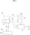
- Fig. 7 is a diagram schematically showing another example of the accelerated cooling operation of the cryocooler 10 according to the embodiment.
- the other compressor 13 having a larger capacity than the compressor 12 may be connected to the expander motor 42 via the inverter 60, as a power source, and may be used for the accelerated cooling operation of the cryocooler 10.
- the other compressor 13 is connected to the external power source 46, and electric power having a power source frequency (for example, 50 Hz or 60 Hz) is supplied from the external power source 46 to the compressor 13.
- a power source frequency for example, 50 Hz or 60 Hz
- the inverter 60 is connected to the expander motor 42 by the power supply cable 48
- the compressor 13 is connected to the inverter 60 by the power supply cable 49.
- the gas line 62 is also removed from the compressor 12 and is connected to the other compressor 13.
- the accelerated cooling operation of the cryocooler 10 may be performed using the other compressor 13 having a larger capacity than the compressor 12.
- more working gas can be supplied from the other compressor 13 to the expander 14 as compared with the normal cooling operation using the compressor 12.
- the superconducting coil 102 of the superconducting device 100 can be re-cooled to a desired cooling temperature in a short time by using the accelerated cooling operation of the cryocooler 10.
- Fig. 8 is a diagram schematically showing another example of the accelerated cooling operation of the cryocooler 10 according to the embodiment.
- the compressor 12 serving as a power source is electrically connected to the inverter 60 by the power supply cable 49
- the inverter 60 is electrically connected to the expander motor 42 of the expander 14 by the power supply cable 48.
- the method for operating the cryocooler 10 according to the embodiment may further include temporarily increasing the amount of the working gas of the cryocooler 10 during the execution of the accelerated cooling operation.
- a buffer volume 70 may be connected to the gas line 62 of the cryocooler 10.
- the buffer volume 70 is a volume for storing the working gas, and may be, for example, a buffer tank.
- the pressure of the buffer volume 70 may be an intermediate pressure (for example, an average pressure of the high pressure and the low pressure) between the pressure of the high pressure line 63 and the pressure of the low pressure line 64 during the operation of the cryocooler 10.
- a supply valve 72 connects the buffer volume 70 to the low pressure line 64, and a collection valve 74 connects the buffer volume 70 to the high pressure line 63.
- Each of the supply valve 72 and the collection valve 74 may be an on/off valve or a flow rate control valve, and may be an electromagnetic valve, for example.
- the supply valve 72 when the supply valve 72 is opened during the operation of the cryocooler 10, the working gas is supplied from the buffer volume 70 to the low pressure line 64 through the supply valve 72.
- the supply valve 72 When the supply valve 72 is closed, the supply of the working gas from the buffer volume 70 to the low pressure line 64 is stopped.
- the collection valve 74 when the collection valve 74 is opened, the working gas is collected from the high pressure line 63 to the buffer volume 70 through the collection valve 74.
- the collection valve 74 When the collection valve 74 is closed, the collection of the working gas from the high pressure line 63 to the buffer volume 70 is stopped. In this way, the amount of the working gas circulating through the gas line 62 can be adjusted by opening and closing the supply valve 72 and the collection valve 74.
- the supply valve 72 is opened, so that the working gas is supplied from the buffer volume 70 to the low pressure line 64, and the amount of the working gas circulating through the cryocooler 10 can be increased.
- the collection valve 74 is opened, so that the working gas is collected from the high pressure line 63 to the buffer volume 70, and the amount of the working gas circulating through the cryocooler 10 can be restored.
- the cooling capacity can be improved by temporarily increasing the amount of the working gas of the cryocooler 10 during the execution of the accelerated cooling operation, and it is possible to assist in the re-cooling of an object to be cooled, such as the superconducting coil 102.
- Fig. 9 is a diagram schematically showing another example of the accelerated cooling operation of the cryocooler 10 according to the embodiment.
- the compressor 12 serving as a power source is electrically connected to the expander motor 42 of the expander 14 via the inverter 60 for the accelerated cooling operation of the cryocooler 10.
- the superconducting coil 102 may be cooled by using an additional cooling device, for example, a circulation cooling device 80, which supplies a cooled gas to the periphery of the superconducting coil 102.
- a circulation cooling device 80 which supplies a cooled gas to the periphery of the superconducting coil 102.
- the circulation cooling device 80 is configured to cool a refrigerant gas to a cryogenic temperature and circulate the cooled refrigerant gas to the superconducting device 100.
- the refrigerant gas is a helium gas in the embodiment, other gases such as a nitrogen gas, for example, may be used in some cases.
- the circulation cooling device 80 includes a circulation device 82, at least one (in the embodiment, a plurality of, for example, four) cryocooler 84, a vacuum vessel 86, a supply line 88, and a collection line 90.
- the circulation device 82 is configured to send the refrigerant gas collected from the collection line 90 to the supply line 88, thereby allowing the refrigerant gas to be circulated between the circulation cooling device 80 and the superconducting device 100.
- the circulation device 82 is installed inside the vacuum vessel 86.
- the circulation device 82 may be, for example, a fan.
- the circulation device 82 may be a compressor that is disposed in the surrounding environment (for example, a room temperature atmosphere) outside the vacuum vessel 86.
- the compressor may be a compressor different from the compressor 12 of the cryocooler 10.
- the refrigerant gas that is sent to the supply line 88 is pressurized to, for example, a pressure of 1 MPa or higher and 2 MPa or lower by the circulation device 82.
- Each of the plurality of cryocoolers 84 includes a cooling stage 84a for cooling the refrigerant gas, and is installed at the vacuum vessel 86 such that the cooling stage 84a is disposed within the vacuum vessel 86.
- the cryocooler 84 may be, for example, a Gifford-McMahon (GM) cryocooler, similarly to the cryocooler 10 of the superconducting device 100.
- the cryocooler 84 may be a single stage type and can provide a cooling temperature (for example, a liquid nitrogen temperature) that is selected from a range of 100 K to 10 K, for example, to the cooling stage 84a.
- the vacuum vessel 86 is an insulated vacuum vessel that provides a cryogenic vacuum environment inside, and is also called a cryostat.
- the supply line 88 and the collection line 90 are accommodated in the vacuum vessel 86 together with the cooling stage 84a of the cryocooler 84.
- the wall surface of the vacuum vessel 86 is provided with a refrigerant gas supply port 92 and a refrigerant gas collection port 94.
- the supply line 88 connects the circulation device 82 to the refrigerant gas supply port 92, and the collection line 90 connects the refrigerant gas collection port 94 to the refrigerant gas supply port 92.
- the supply line 88 includes a heat exchanger 88a that cools the refrigerant gas by heat exchange with the cooling stage 84a of the cryocooler 84.
- the heat exchanger 88a is provided for each cooling stage 84a, and these heat exchangers 88a are connected in series.
- the vacuum vessel 106 of the superconducting device 100 may be provided with a refrigerant container 112, a refrigerant inlet 114, and a refrigerant outlet 116.
- the refrigerant container 112 accommodates the superconducting coil 102 and is disposed to be surrounded by the heat shield 104 inside the vacuum vessel 106.
- the refrigerant inlet 114 is a supply port for the refrigerant gas from the outside of the vacuum vessel 106 to the refrigerant container 112, and the refrigerant outlet 116 is a collection port for the refrigerant gas from the refrigerant container 112 to the outside of the vacuum vessel 106.
- the circulation cooling device 80 is connected to the superconducting device 100 by a supply-side transfer line 96 and a collection-side transfer line 98.
- the supply-side transfer line 96 connects the refrigerant gas supply port 92 of the circulation cooling device 80 to the refrigerant inlet 114 of the superconducting device 100
- the collection-side transfer line 98 connects the refrigerant gas collection port 94 of the circulation cooling device 80 to the refrigerant outlet 116 of the superconducting device 100.
- the supply-side transfer line 96 and the collection-side transfer line 98 may be flexible tubes compatible with the refrigerant gas cooled to a cryogenic temperature.
- the refrigerant gas sequentially passes through the plurality of heat exchangers 88a connected in series on the supply line 88, and is cooled by the cooling stage 84a of each of the cryocoolers 84.
- the refrigerant gas cooled to the cooling temperature of the cooling stage 84a in this way is supplied to the refrigerant container 112 of the superconducting device 100 through the supply-side transfer line 96, and cools the superconducting coil 102.
- the refrigerant gas is collected from the refrigerant container 112 to the collection line 90 of the circulation cooling device 80 through the collection-side transfer line 98, and is sent to the supply line 88 again by the circulation device 82.
- a liquid refrigerant such as liquid nitrogen is not used.
- the circulation cooling device 80 can cool the superconducting coil 102 of the superconducting device 100 to the cooling temperature of the refrigerant gas of the circulation cooling device 80. Thereafter, the operation of the circulation cooling device 80 is stopped, and the circulation cooling device 80 is removed from the superconducting device 100.
- an additional cooling device for example, the circulation cooling device 80 can be used in combination, so that it is possible to assist in the re-cooling of the object to be cooled, such as the superconducting coil 102.
- the features described in connection with a certain embodiment may be combined with the features described in connection with another embodiment.
- the use of the other compressor 13 referred to with reference to Fig. 7 may be used in combination with the buffer volume 70 referred to with reference to Fig. 8 .
- the other compressor 13 may be used in combination with the circulation cooling device 80 referred to with reference to Fig. 9 .
- the buffer volume 70 and the circulation cooling device 80 may be used in combination.
- the compressor 12 is used as the power source of the expander 14. However, this is not essential.
- the expander 14 may be connected to the external power source 46 without passing through the compressor 12, and may be supplied with power from the external power source 46.
- cryocooler 10 is a two-stage GM cryocooler
- the cryocooler 10 may be a single-stage or multi-stage GM cryocooler, and may be a pulse tube cryocooler, a Stirling cryocooler, or other types of cryocoolers.
- cryocooler 84 is also not limited to the GM cryocooler, and may be a pulse tube cryocooler, a Stirling cryocooler, or other cryocoolers.
- the superconducting device 100 may configure a part of, for example, a single crystal pulling device, an NMR system, an accelerator such as a cyclotron, a high-energy physical system such as a nuclear fusion system, or other equipment that utilizes a high magnetic field.
- the present invention can be used in the field of a method for operating a cryocooler.
Landscapes
- Engineering & Computer Science (AREA)
- Physics & Mathematics (AREA)
- Mechanical Engineering (AREA)
- Thermal Sciences (AREA)
- General Engineering & Computer Science (AREA)
- Condensed Matter Physics & Semiconductors (AREA)
- General Physics & Mathematics (AREA)
- Compressors, Vaccum Pumps And Other Relevant Systems (AREA)
- Containers, Films, And Cooling For Superconductive Devices (AREA)
Abstract
Description
- The present invention relates to a method for operating a cryocooler.
- One of the main uses of a cryocooler is to cool a superconducting magnet. For that purpose, so-called immersion cooling in which the entire superconducting magnet is immersed in liquid helium is often used in the related art. The cryocooler is used to re-condense the vaporized liquid helium.
- In general, the cryocooler may stop the cooling operation, for example, in order to receive regular maintenance, or suddenly due to a failure or some abnormality. In the immersion cooling, even when the cryocooler is stopped, the liquid helium can contribute to cooling and maintaining the temperature of an object to be cooled such as a superconducting magnet.
- [PTL 1]
PCT Japanese Translation Patent Publication No. 2020-515038 - However, the immersion cooling system requires a large amount (for example, several hundred liters or more) of liquid helium. Therefore, against the background of the recent tight global helium supply and demand, research and development of a helium-saving cooling method in which the amount of liquid helium used is significantly reduced compared to the immersion cooling is being conducted. In the helium-saving cooling, a cryocooler serves as a main (or only) cooling source. Therefore, unlike the immersion cooling, the object to be cooled may be significantly heated due to input heat from the surrounding environment during the operation stop of the cryocooler. In that case, there is a concern that it may take a considerable time to re-cool to a desired cooling temperature after the operation of the cryocooler is resumed. The downtime in which the object to be cooled cannot be used is prolonged, which is undesirable.
- One exemplary object of an aspect of the present invention is to provide a method for operating a cryocooler that assists in re-cooling of an object to be cooled.
- According to an aspect of the present invention, there is provided a method for operating a cryocooler. The cryocooler includes an expander having an expander motor that is connected to a power source by a power supply cable and is capable of being driven at a power source frequency. The method includes: releasing connection between the power source and the expander motor by the power supply cable; connecting the power source and the expander motor via an inverter; executing an accelerated cooling operation of the cryocooler in which the power source frequency is converted into an operation frequency higher than the power source frequency by the inverter and the expander motor is driven at the converted operation frequency; and removing the inverter and reconnecting the power source and the expander motor, after the accelerated cooling operation is stopped.
- Any combination of the above components or components or expressions of the present invention that are mutually replaced between methods, devices, systems, or the like are also effective as aspects of the present invention.
- According to the present invention, it is possible to provide a method for operating a cryocooler that assists in re-cooling of an object to be cooled.
-
-
Fig. 1 is a diagram schematically showing a superconducting device according to an embodiment. -
Fig. 2 is a diagram schematically showing a cryocooler according to the embodiment. -
Fig. 3 is a diagram schematically showing the cryocooler according to the embodiment. -
Fig. 4 is a flowchart illustrating a method for operating the cryocooler according to the embodiment. -
Fig. 5 is a diagram schematically showing an example of accelerated cooling operation of the cryocooler according to the embodiment. -
Fig. 6 is a diagram schematically showing another example of the accelerated cooling operation of the cryocooler according to the embodiment. -
Fig. 7 is a diagram schematically showing another example of the accelerated cooling operation of the cryocooler according to the embodiment. -
Fig. 8 is a diagram schematically showing another example of the accelerated cooling operation of the cryocooler according to the embodiment. -
Fig. 9 is a diagram schematically showing another example of the accelerated cooling operation of the cryocooler according to the embodiment. - Hereinafter, embodiments for carrying out the present invention will be described in detail with reference to the drawings. In the description and drawings, identical or equivalent components, members, and processing are denoted by the same reference numerals, and overlapping description is omitted as appropriate. The scale or shape of each part that is shown in the drawings is conveniently set for ease of description and is not limitedly interpreted unless otherwise specified. The embodiments are exemplary and do not limit the scope of the present invention in any way. All features or combinations thereof described in the embodiments are not essential to the invention.
-
Fig. 1 is a diagram schematically showing asuperconducting device 100 according to an embodiment.Figs. 2 and3 are diagrams schematically showing acryocooler 10 according to the embodiment. - As shown in
Fig. 1 , thesuperconducting device 100 includes asuperconducting coil 102, aheat shield 104, avacuum vessel 106, and acryocooler 10. In the embodiment, thesuperconducting device 100 configures, for example, a part of a magnetic resonance imaging (MRI) system. - The
superconducting coil 102 is cooled to a cryogenic temperature equal to or lower than a critical temperature at which superconductivity is manifested by thecryocooler 10 during use. An exciting current is supplied to thesuperconducting coil 102 from an external power source (not shown) disposed outside thevacuum vessel 106, whereby a strong magnetic field can be generated. - The
heat shield 104 is disposed around thesuperconducting coil 102, and is configured to thermally protect thesuperconducting coil 102 from radiant heat that can enter from the outside of theheat shield 104. Theheat shield 104 is formed of a metal material such as copper, for example, or another material having high thermal conductivity. - The
vacuum vessel 106 is an insulated vacuum vessel that provides a cryogenic vacuum environment suitable for bringing thesuperconducting coil 102 into a superconducting state, and is also called a cryostat. Theheat shield 104 is accommodated in thevacuum vessel 106 together with thesuperconducting coil 102. Thevacuum vessel 106 is formed of a metal material such as stainless steel, for example, or another appropriate high strength material so as to withstand ambient pressure (for example, atmospheric pressure). - As an example, the
cryocooler 10 is a two-stage Gifford-McMahon (GM) cryocooler. InFig. 2 , acompressor 12 and anexpander 14 that configure thecryocooler 10 are schematically shown, and inFig. 3 , an internal structure of theexpander 14 of thecryocooler 10 is shown. Theexpander 14 is also referred to as a cold head. - The
compressor 12 is disposed outside thevacuum vessel 106, and theexpander 14 is installed on thevacuum vessel 106 such that a low-temperature section thereof is disposed inside thevacuum vessel 106. Thecompressor 12 is configured to collect a working gas of thecryocooler 10 from theexpander 14, to pressurize the collected working gas, and to supply the working gas to theexpander 14 again. A refrigeration cycle (for example, a GM cycle) of thecryocooler 10 is configured by thecompressor 12 and theexpander 14, and thus, theexpander 14 can provide cryogenic cooling. The working gas is typically a helium gas. However, other suitable gases may be used. For the sake of understanding, a flow direction of the working gas is shown by an arrow in each drawing. - During the operation of the
superconducting device 100, a first-stage cooling stage (for example, afirst cooling stage 33 described later) of thecryocooler 10 is cooled to a first cooling temperature, for example, a temperature in a range of 30 K to 50 K, and a second-stage cooling stage (for example, asecond cooling stage 35 described later) of thecryocooler 10 is cooled to a second cooling temperature lower than the first cooling temperature, for example, a temperature in a range of 3 K to 20 K (for example, about 4 K). Theheat shield 104 is thermally coupled to the first-stage cooling stage of thecryocooler 10 and is cooled to the first cooling temperature. Thesuperconducting coil 102 is thermally coupled to the second-stage cooling stage of thecryocooler 10 and is cooled to the second cooling temperature. - The
superconducting coil 102 may be cooled by conduction cooling by the second-stage cooling stage of thecryocooler 10. For example, as shown inFig. 1 , thesuperconducting coil 102 may be physically connected to the second-stage cooling stage of thecryocooler 10 by a flexible or rigidheat transfer member 108 formed of a material having high thermal conductivity such as copper, similarly to theheat shield 104. Thesuperconducting coil 102 may be directly coupled to the second-stage cooling stage of thecryocooler 10 without theheat transfer member 108. - Alternatively, the
superconducting device 100 may be a helium-saving type device that is cooled by circulating a small amount (for example, several liters or less) of cryogenic refrigerant through thesuperconducting coil 102. In this case, thesuperconducting device 100 may include a cryogenic refrigerant circuit disposed on the surface and/or the inside of thesuperconducting coil 102. This refrigerant circuit configures a superconducting coil cooling system together with thecryocooler 10. Thecryocooler 10 cools the cryogenic refrigerant of the refrigerant circuit, and the cooled cryogenic refrigerant cools thesuperconducting coil 102 by flowing through the refrigerant circuit. The cryogenic refrigerant may be, for example, liquid helium or high-pressure helium gas enclosed in the cryogenic refrigerant circuit. - An exemplary configuration of the
cryocooler 10 that can be used in the embodiment will be described with reference toFigs. 2 and3 . Thecompressor 12 may be, for example, a scroll type, a rotary type, or another appropriate pump for pressurizing the working gas. In the embodiment, thecompressor 12 is configured to discharge a fixed and constant working gas flow rate. Alternatively, thecompressor 12 may be configured to allow a variable flow rate of the working gas to be discharged. For example, a cooling device such as a chiller may be attached to thecompressor 12 in order to remove the compression heat that is generated by compressing the working gas. - In general, both the pressure of the working gas that is supplied from the
compressor 12 to theexpander 14 and the pressure of the working gas that is collected from theexpander 14 to thecompressor 12 are considerably higher than the atmospheric pressure, and can be called a first high pressure and a second high pressure, respectively. For convenience of description, the first high pressure and the second high pressure are also simply referred to as high pressure and low pressure, respectively. Typically, the high pressure is, for example, a pressure in a range of 2 to 3 MPa. The low pressure is, for example, a pressure in a range of 0.5 to 1.5 MPa and is, for example, about 0.8 MPa. For the sake of understanding, the flow direction of the working gas is shown by an arrow. - The
expander 14 includes acryocooler cylinder 16 and adisplacer assembly 18. Thecryocooler cylinder 16 guides the linear reciprocating motion of thedisplacer assembly 18, and forms expansion chambers (32, 34) for the working gas between itself and thedisplacer assembly 18. In addition, theexpander 14 includes apressure switching valve 40 that determines an intake start timing of the working gas into the expansion chamber and an exhaust start timing of the working gas from the expansion chamber. - In the present specification, in order to describe a positional relationship between the components of the
cryocooler 10, for convenience, a side close to a top dead center of the axial reciprocation of the displacer is described as "upper", and a side close to a bottom dead center is described as "lower". The top dead center is the position of the displacer where the volume of an expansion space is maximized, and the bottom dead center is the position of the displacer where the volume of the expansion space is minimized. Since a temperature gradient is generated in which a temperature drops from the upper side to the lower side in the axial direction during the operation of thecryocooler 10, the upper side can be referred to as a high temperature side and the lower side can be referred to as a low temperature side. - The
cryocooler cylinder 16 includes afirst cylinder 16a and asecond cylinder 16b. As an example, thefirst cylinder 16a and thesecond cylinder 16b are members having a cylindrical shape, and thesecond cylinder 16b has a smaller diameter than thefirst cylinder 16a. Thefirst cylinder 16a and thesecond cylinder 16b are coaxially disposed, and a lower end of thefirst cylinder 16a is rigidly connected to an upper end of thesecond cylinder 16b. - The
displacer assembly 18 includes afirst displacer 18a and asecond displacer 18b, which are connected to each other, and these displacers move integrally. As an example, thefirst displacer 18a and thesecond displacer 18b are members having a cylindrical shape, and thesecond displacer 18b has a smaller diameter than thefirst displacer 18a. Thefirst displacer 18a and thesecond displacer 18b are coaxially disposed. - The
first displacer 18a is accommodated in thefirst cylinder 16a, and thesecond displacer 18b is accommodated in thesecond cylinder 16b. Thefirst displacer 18a can reciprocate in an axial direction along thefirst cylinder 16a, and thesecond displacer 18b can reciprocate in the axial direction along thesecond cylinder 16b. - As shown in
Fig. 3 , thefirst displacer 18a accommodates afirst regenerator 26. Thefirst regenerator 26 is formed by filling a tubular main body portion of thefirst displacer 18a with a wire mesh such as copper, for example, or another appropriate first regenerator material. An upper lid portion and a lower lid portion of thefirst displacer 18a may be provided as separate members from the main body portion of thefirst displacer 18a, and the upper lid portion and the lower lid portion of thefirst displacer 18a may be fixed to the main body by appropriate means such as fastening or welding, whereby the first regenerator material may be accommodated in thefirst displacer 18a. - Similarly, the
second displacer 18b accommodates asecond regenerator 28. Thesecond regenerator 28 is formed by filling a tubular main body portion of thesecond displacer 18b with a non-magnetic regenerator material such as bismuth, a magnetic regenerator material such as HoCu2, or another appropriate second regenerator material. The second regenerator material may be formed in a granular shape. An upper lid portion and a lower lid portion of thesecond displacer 18b may be provided as separate members from the main body portion of thesecond displacer 18b, and the lower lid portion of the upper lid portion of thesecond displacer 18b may be fixed to the main body by appropriate means such as fastening or welding, whereby the second regenerator material may be accommodated in thesecond displacer 18b. - The
displacer assembly 18 forms aroom temperature chamber 30, afirst expansion chamber 32, and asecond expansion chamber 34 inside thecryocooler cylinder 16. Theexpander 14 includes thefirst cooling stage 33 and thesecond cooling stage 35 for heat exchange with a desired object or medium to be cooled by thecryocooler 10. Theroom temperature chamber 30 is formed between the upper lid portion of thefirst displacer 18a and the upper portion of thefirst cylinder 16a. Thefirst expansion chamber 32 is formed between the lower lid portion of thefirst displacer 18a and thefirst cooling stage 33. Thesecond expansion chamber 34 is formed between the lower lid portion of thesecond displacer 18b and thesecond cooling stage 35. Thefirst cooling stage 33 is fixed to the lower portion of thefirst cylinder 16a to surround thefirst expansion chamber 32, and thesecond cooling stage 35 is fixed to the lower portion of thesecond cylinder 16b to surround thesecond expansion chamber 34. - The
first regenerator 26 is connected to theroom temperature chamber 30 through a workinggas flow path 36a formed in the upper lid portion of thefirst displacer 18a, and is connected to thefirst expansion chamber 32 through a workinggas flow path 36b formed in the lower lid portion of thefirst displacer 18a. Thesecond regenerator 28 is connected to thefirst regenerator 26 through a workinggas flow path 36c formed from the lower lid portion of thefirst displacer 18a to the upper lid portion of thesecond displacer 18b. In addition, thesecond regenerator 28 is connected to thesecond expansion chamber 34 through a workinggas flow path 36d formed in the lower lid portion of thesecond displacer 18b. - The working gas flow between the
first expansion chamber 32, thesecond expansion chamber 34, and theroom temperature chamber 30 is not the clearance between thecryocooler cylinder 16 and thedisplacer assembly 18, and afirst seal 38a and asecond seal 38b may be provided to be guided to thefirst regenerator 26 and thesecond regenerator 28. Thefirst seal 38a may be mounted to the upper lid portion of thefirst displacer 18a to be disposed between thefirst displacer 18a and thefirst cylinder 16a. Thesecond seal 38b may be mounted to the upper lid portion of thesecond displacer 18b to be disposed between thesecond displacer 18b and thesecond cylinder 16b. - As shown in
Fig. 2 , theexpander 14 includes acryocooler housing 20 that accommodates thepressure switching valve 40. Thecryocooler housing 20 is coupled to thecryocooler cylinder 16, thereby configuring a hermetic container that accommodates thepressure switching valve 40 and thedisplacer assembly 18. - As shown in
Fig. 3 , thepressure switching valve 40 includes ahigh pressure valve 40a and alow pressure valve 40b, and is configured to generate periodic pressure fluctuations in thecryocooler cylinder 16. A working gas discharge port of thecompressor 12 is connected to theroom temperature chamber 30 via thehigh pressure valve 40a, and a working gas suction port of thecompressor 12 is connected to theroom temperature chamber 30 via thelow pressure valve 40b. Thehigh pressure valve 40a and thelow pressure valve 40b are configured to be selectively and alternately opened and closed (that is, when one of the valves is open, the other of the valves is closed). - The
pressure switching valve 40 may take the form of a rotary valve. That is, thepressure switching valve 40 may be configured such that thehigh pressure valve 40a and thelow pressure valve 40b are alternately opened and closed by the rotational sliding of a valve disc with respect to a stationary valve main body. In that case, anexpander motor 42 may be connected to thepressure switching valve 40 to rotate the valve disc of thepressure switching valve 40. For example, thepressure switching valve 40 is disposed such that a valve rotation shaft is coaxial with a rotation shaft of theexpander motor 42. - Alternatively, the
high pressure valve 40a and thelow pressure valve 40b may be valves that can be individually controlled. In this case, thepressure switching valve 40 may not be connected to theexpander motor 42. - The
expander motor 42 may be, for example, a permanent magnet type motor that is driven by three-phase alternating current. Theexpander motor 42 is connected to adisplacer drive shaft 44 via amotion conversion mechanism 43 such as a Scotch yoke mechanism, for example. Theexpander motor 42 is attached to thecryocooler housing 20. Themotion conversion mechanism 43 is accommodated in thecryocooler housing 20 as with thepressure switching valve 40. Themotion conversion mechanism 43 converts the rotary motion output by theexpander motor 42 into a linear reciprocating motion of thedisplacer drive shaft 44. Thedisplacer drive shaft 44 extends from themotion conversion mechanism 43 into theroom temperature chamber 30, and is fixed to the upper lid portion of thefirst displacer 18a. The rotation of theexpander motor 42 is converted into an axial reciprocation of thedisplacer drive shaft 44 by themotion conversion mechanism 43, and thedisplacer assembly 18 reciprocates linearly in thecryocooler cylinder 16 in the axial direction. - In
Fig. 2 , the electrical connection between thecompressor 12 and theexpander 14 in a normal cooling operation of thecryocooler 10 is shown. In the embodiment, thecompressor 12 is connected to anexternal power source 46 such as a commercial power source (three-phase alternating-current power source), and electric power having a power source frequency (for example, 50 Hz or 60 Hz) is supplied from theexternal power source 46 to thecompressor 12. - The
compressor 12 is used as a power source for theexpander 14. That is, theexpander motor 42 is connected to thecompressor 12 as a power source by apower supply cable 48, and can be driven at the power source frequency. Thepower supply cable 48 is, for example, a power supply line of AC 200 V. In the normal cooling operation of thecryocooler 10, theexpander motor 42 is driven at a constant operation frequency equal to the power source frequency. Therefore, in the normal cooling operation, the frequency (the number of times per unit time) of the refrigeration cycle of thecryocooler 10 is constant. As will be described later, in a case where theexpander motor 42 is connected to an inverter, the operation frequency of the expander motor 42 (and the frequency of the refrigeration cycle of the cryocooler 10) can be controlled by the inverter. - In addition, the
cryocooler 10 includes agas line 62 that circulates the working gas between thecompressor 12 and theexpander 14. Thegas line 62 includes ahigh pressure line 63 connecting thecompressor 12 to theexpander 14 to supply the working gas from thecompressor 12 to theexpander 14, and alow pressure line 64 connecting thecompressor 12 to theexpander 14 to collect the working gas from theexpander 14 to thecompressor 12. Thecryocooler housing 20 of theexpander 14 is provided with a highpressure gas inlet 22 and a low pressure gas outlet 24. The highpressure gas inlet 22 of theexpander 14 is connected to a highpressure gas outlet 50 of thecompressor 12 by thehigh pressure line 63, and the low pressure gas outlet 24 of theexpander 14 is connected to a lowpressure gas inlet 51 of thecompressor 12 by thelow pressure line 64. Each of thehigh pressure line 63 and thelow pressure line 64 may be a flexible pipe, a rigid pipe, or a combination thereof. - When the
compressor 12 and theexpander motor 42 are operated, thecryocooler 10 generates periodic volume fluctuations and pressure fluctuations of the working gas synchronized with the periodic volume fluctuations in thefirst expansion chamber 32 and thesecond expansion chamber 34. Typically, in an intake process, thelow pressure valve 40b is closed and thehigh pressure valve 40a is opened, whereby the high pressure working gas flows from thecompressor 12 into theroom temperature chamber 30 through thehigh pressure valve 40a, is supplied tofirst expansion chamber 32 through thefirst regenerator 26, and is supplied to thesecond expansion chamber 34 through thesecond regenerator 28. In this manner, thefirst expansion chamber 32 and thesecond expansion chamber 34 are pressurized from the low pressure to the high pressure. In this case, thedisplacer assembly 18 is moved upward from the bottom dead center to the top dead center, and the volumes of thefirst expansion chamber 32 and thesecond expansion chamber 34 are increased. When thehigh pressure valve 40a is closed, the intake process ends. - In an exhaust process, the
high pressure valve 40a is closed and thelow pressure valve 40b is opened, whereby the high pressurefirst expansion chamber 32 and the high pressuresecond expansion chamber 34 are opened to the low pressure working gas suction port of thecompressor 12, and thus the working gas expands in thefirst expansion chamber 32 and thesecond expansion chamber 34. As a result, the low pressure working gas is discharged from thefirst expansion chamber 32 and thesecond expansion chamber 34 to theroom temperature chamber 30 through thefirst regenerator 26 and thesecond regenerator 28. In this case, thedisplacer assembly 18 is moved downward from the top dead center to the bottom dead center, and the volumes of thefirst expansion chamber 32 and thesecond expansion chamber 34 are reduced. The working gas is collected from theexpander 14 to thecompressor 12 through thelow pressure valve 40b. When thelow pressure valve 40b is closed, the exhaust process ends. - In this way, a refrigeration cycle such as a GM cycle, for example, is configured in the
cryocooler 10, and thefirst cooling stage 33 and thesecond cooling stage 35 are cooled to a desired cryogenic temperature. Thefirst cooling stage 33 is cooled to the first cooling temperature, and thesecond cooling stage 35 is cooled to the second cooling temperature lower than the first cooling temperature. By thecryocooler 10, thesuperconducting coil 102 is cooled to a cryogenic temperature equal to or lower than a critical temperature at which superconductivity is manifested. Thesuperconducting coil 102 cooled to the cryogenic temperature can generate a desired high magnetic field by being supplied with power from a coil power source (not shown) disposed outside thevacuum vessel 106. In this way, thesuperconducting device 100 such as an MRI system is operated. - Typically, the
superconducting device 100 can be continuously operated for a long period (for example, several months or several years or more) once the operation is started. After such a long-term normal operation, thesuperconducting device 100 and thecryocooler 10 may be inspected, or be subjected to maintenance such as repair or replacement as needed. Alternatively, although it is not desirable, even in a case where a failure or some abnormality occurs in thesuperconducting device 100 or thecryocooler 10, maintenance is performed. - During the maintenance, the operation of the
superconducting device 100 is stopped, that is, the current supply to thesuperconducting coil 102 is stopped, and the cooling operation of thecryocooler 10 is also stopped. In the immersion cooling of the related art in which thesuperconducting coil 102 is immersed in a large amount of liquid helium and is cooled to a cryogenic temperature, even when thecryocooler 10 is stopped, thesuperconducting coil 102 can continue to be cooled by the liquid helium. Therefore, the cooling of thesuperconducting coil 102 can be maintained until the end of the maintenance, and thereafter, the operation of thesuperconducting device 100 can be promptly resumed. - In contrast, in the helium-saving cooling, the
cryocooler 10 serves as a main (or only) cooling source. Therefore, unlike the immersion cooling, thesuperconducting coil 102 may be significantly heated by the input heat from the surrounding environment during the operation stop of thecryocooler 10. In that case, when the maintenance is ended, thesuperconducting coil 102 has to be re-cooled to a target cooling temperature by thecryocooler 10. A considerable time is required for the re-cooling although the time depends on the specifications such as the size or the weight of thesuperconducting device 100. It is not desirable that the downtime in which thesuperconducting device 100 cannot be used is prolonged. Therefore, in the embodiment, the accelerated cooling operation of thecryocooler 10 described below is proposed. -
Fig. 4 is a flowchart illustrating a method for operating thecryocooler 10 according to the embodiment.Fig. 5 is a diagram schematically showing an example of the accelerated cooling operation of thecryocooler 10 according to the embodiment. - The present method is performed after the end of the normal cooling operation of the
cryocooler 10 described above. The present method may be performed after the end of the maintenance of thesuperconducting device 100 or thecryocooler 10, which is performed as necessary, after the end of the normal cooling operation. - In the present method, first, the connection between the power source (that is, the compressor 12) and the
expander motor 42 by thepower supply cable 48 is released (S10 inFig. 4 ). For example, a worker such as a service engineer removes one end of thepower supply cable 48 from a terminal of thecompressor 12 and removes the other end of thepower supply cable 48 from a terminal of theexpander motor 42. In this way, the electrical connection between thecompressor 12 and theexpander motor 42 is once released. - Next, the power source (that is, the compressor 12) and the
expander motor 42 are connected to each other via an inverter 60 (S20 inFig. 4 ). The worker connects theexpander motor 42 and theinverter 60 to each other by using thepower supply cable 48. The worker connects one end of thepower supply cable 48 to the terminal of theexpander motor 42 again, and connects the other end of thepower supply cable 48 to an output terminal of theinverter 60. In addition, the worker prepares an additionalpower supply cable 49, connects one end of thepower supply cable 49 to an input terminal of theinverter 60, and connects the other end of thepower supply cable 49 to a terminal of thecompressor 12. In this way, as shown inFig. 5 , the electrical connection between thecompressor 12 and theexpander motor 42 is re-established via theinverter 60. Thecompressor 12 and theinverter 60 may be connected to each other by the originalpower supply cable 48, and theexpander motor 42 and theinverter 60 may be connected to each other by the additionalpower supply cable 49. - The
inverter 60 is configured to convert a power source frequency that is input (supplied) from thecompressor 12 serving as a power source into an operation frequency higher than the power source frequency and output the electric power having the converted higher operation frequency to theexpander motor 42. Theinverter 60 may be configured to be capable of adjusting the operation frequency to be output. The operation frequency that is output from theinverter 60 may be selected from a frequency range higher than, for example, 50 Hz (or 60 Hz) and lower than, for example, 100 Hz. The operation frequency can be appropriately selected by the worker operating theinverter 60. - The
inverter 60 may be mounted in a portable inverter box. The worker can easily bring theinverter 60 to the site, which is convenient. Theinverter 60 may be disposed inside a casing of the inverter box, and an input terminal and an output terminal of theinverter 60 may be provided on the casing surface of the inverter box. - Subsequently, the accelerated cooling operation of the
cryocooler 10 is executed (S30 inFig. 4 ). When thecryocooler 10 is started, the power source frequency that is input from thecompressor 12 to theinverter 60 through thepower supply cable 48 is converted into a preselected operation frequency higher than the power source frequency by theinverter 60, and the converted operation frequency is output from theinverter 60 to theexpander motor 42 through thepower supply cable 49. - In this way, the
expander motor 42 is driven at a higher operation frequency compared to the normal cooling operation of thecryocooler 10. Therefore, in the accelerated cooling operation, thecryocooler 10 is operated with a higher cooling capacity compared to the normal cooling operation. In this way, thecryocooler 10 can be rapidly cooled, and an object to be cooled, such as thesuperconducting coil 102, can be quickly cooled to a target cooling temperature. - In a case where the cooling temperature of the
cryocooler 10 or thesuperconducting coil 102 can be identified on the spot, the worker may compare the cooling temperature with the target temperature while executing the accelerated cooling operation of thecryocooler 10. The accelerated cooling operation may be continued until the cooling temperature falls to the target temperature. The accelerated cooling operation may be stopped when the cooling temperature reaches the target temperature. - Alternatively, the
cryocooler 10 may have a timer. The timer may be provided in theinverter 60. A time from the start to the end of the accelerated cooling operation may be set in advance in the timer, and the accelerated cooling operation may be automatically ended by the elapse of the setting time. The setting time may be set by the worker. - After the accelerated cooling operation is stopped, the
inverter 60 is removed, and the power source (that is, the compressor 12) and theexpander motor 42 are reconnected to each other (S40 inFig. 4 ). Thecompressor 12 and theexpander motor 42 may be connected to each other again by thepower supply cable 48. The electrical connection between thecompressor 12 and theexpander 14 returns to the initial state shown inFig. 2 . In this way, thecryocooler 10 can resume the normal cooling operation. - Therefore, according to the embodiment, it is possible to provide a method for operating the
cryocooler 10 that assists in the re-cooling of the object to be cooled such as thesuperconducting coil 102. The object to be cooled can be re-cooled to a desired cooling temperature in a short time by using the accelerated cooling operation of thecryocooler 10. -
Fig. 6 is a diagram schematically showing another example of the accelerated cooling operation of thecryocooler 10 according to the embodiment. Similarly to the embodiment described above, in order to perform the accelerated cooling operation of thecryocooler 10, thecompressor 12 serving as a power source is electrically connected to theinverter 60 by thepower supply cable 49, and theinverter 60 is electrically connected to theexpander motor 42 of theexpander 14 by thepower supply cable 48. - The
inverter 60 may be controlled by acontroller 66. That is, thecontroller 66 may be configured to generate a control signal instructing the end of the accelerated cooling operation of thecryocooler 10 and output the control signal to theinverter 60. Thecontroller 66 may be communicably connected to theinverter 60 by asignal cable 67 for transmitting the control signal. Theinverter 60 receives the control signal from thecontroller 66, whereby the accelerated cooling operation of thecryocooler 10 may be ended. - For example, the
controller 66 may be a host controller that controls the superconducting device 100 (for example, the MRI system). Thesuperconducting device 100 may include atemperature sensor 110 that is provided in thesuperconducting coil 102, measures the temperature of thesuperconducting coil 102, and outputs a measured temperature signal indicating the measured temperature of thesuperconducting coil 102 to thecontroller 66. Thecontroller 66 may receive the measured temperature signal from thetemperature sensor 110 and compare the cooling temperature of thesuperconducting coil 102 with a target temperature during the execution of the accelerated cooling operation of thecryocooler 10. In a case where the cooling temperature of thesuperconducting coil 102 is higher than the target temperature, thecontroller 66 may continue the accelerated cooling operation (that is, may not instruct the end of the accelerated cooling operation), and in a case where the cooling temperature of thesuperconducting coil 102 reaches the target temperature, thecontroller 66 may generate a control signal instructing the end of the accelerated cooling operation and output the control signal to theinverter 60. - As shown by a dashed line arrow in
Fig. 6 , the control signal instructing the end of the accelerated cooling operation may be given from thecontroller 66 to theinverter 60 via thecompressor 12. Thecontroller 66 may be connected to thecompressor 12 by asignal cable 68a, and thecompressor 12 may be connected to theinverter 60 by anothersignal cable 68b. - As an alternative, the
controller 66 may be a cryocooler controller that controls thecryocooler 10, instead of the host controller that controls thesuperconducting device 100. The cryocooler controller may be mounted on thecompressor 12. - The
controller 66 is realized by elements or circuits such as a CPU or a memory of a computer as a hardware configuration, and is realized by a computer program or the like as a software configuration. However, inFig. 6 , thecontroller 66 is appropriately depicted as functional blocks which are realized by the cooperation of the hardware configuration and the software configuration. It will be understood by those skilled in the art that these functional blocks can be realized in various ways by combining hardware and software. -
Fig. 7 is a diagram schematically showing another example of the accelerated cooling operation of thecryocooler 10 according to the embodiment. Instead of thecompressor 12, theother compressor 13 having a larger capacity than thecompressor 12 may be connected to theexpander motor 42 via theinverter 60, as a power source, and may be used for the accelerated cooling operation of thecryocooler 10. - The
other compressor 13 is connected to theexternal power source 46, and electric power having a power source frequency (for example, 50 Hz or 60 Hz) is supplied from theexternal power source 46 to thecompressor 13. As for the electrical connection between theother compressor 13 and theexpander 14, theinverter 60 is connected to theexpander motor 42 by thepower supply cable 48, and thecompressor 13 is connected to theinverter 60 by thepower supply cable 49. In addition, thegas line 62 is also removed from thecompressor 12 and is connected to theother compressor 13. - In this way, the accelerated cooling operation of the
cryocooler 10 may be performed using theother compressor 13 having a larger capacity than thecompressor 12. In the accelerated cooling operation, more working gas can be supplied from theother compressor 13 to theexpander 14 as compared with the normal cooling operation using thecompressor 12. Thesuperconducting coil 102 of thesuperconducting device 100 can be re-cooled to a desired cooling temperature in a short time by using the accelerated cooling operation of thecryocooler 10. -
Fig. 8 is a diagram schematically showing another example of the accelerated cooling operation of thecryocooler 10 according to the embodiment. Similarly to the embodiment described above, in order to perform the accelerated cooling operation of thecryocooler 10, thecompressor 12 serving as a power source is electrically connected to theinverter 60 by thepower supply cable 49, and theinverter 60 is electrically connected to theexpander motor 42 of theexpander 14 by thepower supply cable 48. - The method for operating the
cryocooler 10 according to the embodiment may further include temporarily increasing the amount of the working gas of thecryocooler 10 during the execution of the accelerated cooling operation. In order to realize this, abuffer volume 70 may be connected to thegas line 62 of thecryocooler 10. - The
buffer volume 70 is a volume for storing the working gas, and may be, for example, a buffer tank. The pressure of thebuffer volume 70 may be an intermediate pressure (for example, an average pressure of the high pressure and the low pressure) between the pressure of thehigh pressure line 63 and the pressure of thelow pressure line 64 during the operation of thecryocooler 10. Asupply valve 72 connects thebuffer volume 70 to thelow pressure line 64, and acollection valve 74 connects thebuffer volume 70 to thehigh pressure line 63. Each of thesupply valve 72 and thecollection valve 74 may be an on/off valve or a flow rate control valve, and may be an electromagnetic valve, for example. - Therefore, when the
supply valve 72 is opened during the operation of thecryocooler 10, the working gas is supplied from thebuffer volume 70 to thelow pressure line 64 through thesupply valve 72. When thesupply valve 72 is closed, the supply of the working gas from thebuffer volume 70 to thelow pressure line 64 is stopped. Further, when thecollection valve 74 is opened, the working gas is collected from thehigh pressure line 63 to thebuffer volume 70 through thecollection valve 74. When thecollection valve 74 is closed, the collection of the working gas from thehigh pressure line 63 to thebuffer volume 70 is stopped. In this way, the amount of the working gas circulating through thegas line 62 can be adjusted by opening and closing thesupply valve 72 and thecollection valve 74. - When the accelerated cooling operation of the
cryocooler 10 is started, thesupply valve 72 is opened, so that the working gas is supplied from thebuffer volume 70 to thelow pressure line 64, and the amount of the working gas circulating through thecryocooler 10 can be increased. In addition, when the accelerated cooling operation is ended, thecollection valve 74 is opened, so that the working gas is collected from thehigh pressure line 63 to thebuffer volume 70, and the amount of the working gas circulating through thecryocooler 10 can be restored. - In this way, the cooling capacity can be improved by temporarily increasing the amount of the working gas of the
cryocooler 10 during the execution of the accelerated cooling operation, and it is possible to assist in the re-cooling of an object to be cooled, such as thesuperconducting coil 102. -
Fig. 9 is a diagram schematically showing another example of the accelerated cooling operation of thecryocooler 10 according to the embodiment. Similarly to the embodiment described above, thecompressor 12 serving as a power source is electrically connected to theexpander motor 42 of theexpander 14 via theinverter 60 for the accelerated cooling operation of thecryocooler 10. - In addition to the accelerated cooling operation of the
cryocooler 10, thesuperconducting coil 102 may be cooled by using an additional cooling device, for example, acirculation cooling device 80, which supplies a cooled gas to the periphery of thesuperconducting coil 102. - The
circulation cooling device 80 is configured to cool a refrigerant gas to a cryogenic temperature and circulate the cooled refrigerant gas to thesuperconducting device 100. Although the refrigerant gas is a helium gas in the embodiment, other gases such as a nitrogen gas, for example, may be used in some cases. Thecirculation cooling device 80 includes acirculation device 82, at least one (in the embodiment, a plurality of, for example, four)cryocooler 84, avacuum vessel 86, asupply line 88, and acollection line 90. - The
circulation device 82 is configured to send the refrigerant gas collected from thecollection line 90 to thesupply line 88, thereby allowing the refrigerant gas to be circulated between thecirculation cooling device 80 and thesuperconducting device 100. Thecirculation device 82 is installed inside thevacuum vessel 86. Thecirculation device 82 may be, for example, a fan. In addition, thecirculation device 82 may be a compressor that is disposed in the surrounding environment (for example, a room temperature atmosphere) outside thevacuum vessel 86. The compressor may be a compressor different from thecompressor 12 of thecryocooler 10. The refrigerant gas that is sent to thesupply line 88 is pressurized to, for example, a pressure of 1 MPa or higher and 2 MPa or lower by thecirculation device 82. - Each of the plurality of
cryocoolers 84 includes acooling stage 84a for cooling the refrigerant gas, and is installed at thevacuum vessel 86 such that thecooling stage 84a is disposed within thevacuum vessel 86. Thecryocooler 84 may be, for example, a Gifford-McMahon (GM) cryocooler, similarly to thecryocooler 10 of thesuperconducting device 100. Thecryocooler 84 may be a single stage type and can provide a cooling temperature (for example, a liquid nitrogen temperature) that is selected from a range of 100 K to 10 K, for example, to thecooling stage 84a. - The
vacuum vessel 86 is an insulated vacuum vessel that provides a cryogenic vacuum environment inside, and is also called a cryostat. Thesupply line 88 and thecollection line 90 are accommodated in thevacuum vessel 86 together with thecooling stage 84a of thecryocooler 84. The wall surface of thevacuum vessel 86 is provided with a refrigerantgas supply port 92 and a refrigerantgas collection port 94. Thesupply line 88 connects thecirculation device 82 to the refrigerantgas supply port 92, and thecollection line 90 connects the refrigerantgas collection port 94 to the refrigerantgas supply port 92. - The
supply line 88 includes aheat exchanger 88a that cools the refrigerant gas by heat exchange with thecooling stage 84a of thecryocooler 84. Theheat exchanger 88a is provided for each coolingstage 84a, and theseheat exchangers 88a are connected in series. - The
vacuum vessel 106 of thesuperconducting device 100 may be provided with arefrigerant container 112, arefrigerant inlet 114, and arefrigerant outlet 116. Therefrigerant container 112 accommodates thesuperconducting coil 102 and is disposed to be surrounded by theheat shield 104 inside thevacuum vessel 106. Therefrigerant inlet 114 is a supply port for the refrigerant gas from the outside of thevacuum vessel 106 to therefrigerant container 112, and therefrigerant outlet 116 is a collection port for the refrigerant gas from therefrigerant container 112 to the outside of thevacuum vessel 106. - When the accelerated cooling operation of the
cryocooler 10 described above is performed, thecirculation cooling device 80 is connected to thesuperconducting device 100 by a supply-side transfer line 96 and a collection-side transfer line 98. The supply-side transfer line 96 connects the refrigerantgas supply port 92 of thecirculation cooling device 80 to therefrigerant inlet 114 of thesuperconducting device 100, and the collection-side transfer line 98 connects the refrigerantgas collection port 94 of thecirculation cooling device 80 to therefrigerant outlet 116 of thesuperconducting device 100. The supply-side transfer line 96 and the collection-side transfer line 98 may be flexible tubes compatible with the refrigerant gas cooled to a cryogenic temperature. - When the
circulation device 82 operates, the refrigerant gas sequentially passes through the plurality ofheat exchangers 88a connected in series on thesupply line 88, and is cooled by thecooling stage 84a of each of thecryocoolers 84. The refrigerant gas cooled to the cooling temperature of thecooling stage 84a in this way is supplied to therefrigerant container 112 of thesuperconducting device 100 through the supply-side transfer line 96, and cools thesuperconducting coil 102. The refrigerant gas is collected from therefrigerant container 112 to thecollection line 90 of thecirculation cooling device 80 through the collection-side transfer line 98, and is sent to thesupply line 88 again by thecirculation device 82. In the precooling of thesuperconducting device 100 using thecirculation cooling device 80, a liquid refrigerant such as liquid nitrogen is not used. - By continuing such circulation of the refrigerant gas, the
circulation cooling device 80 can cool thesuperconducting coil 102 of thesuperconducting device 100 to the cooling temperature of the refrigerant gas of thecirculation cooling device 80. Thereafter, the operation of thecirculation cooling device 80 is stopped, and thecirculation cooling device 80 is removed from thesuperconducting device 100. - In this way, during the execution of the accelerated cooling operation, an additional cooling device, for example, the
circulation cooling device 80 can be used in combination, so that it is possible to assist in the re-cooling of the object to be cooled, such as thesuperconducting coil 102. - The features described in connection with a certain embodiment may be combined with the features described in connection with another embodiment. For example, the use of the
other compressor 13 referred to with reference toFig. 7 may be used in combination with thebuffer volume 70 referred to with reference toFig. 8 . Alternatively, theother compressor 13 may be used in combination with thecirculation cooling device 80 referred to with reference toFig. 9 . Thebuffer volume 70 and thecirculation cooling device 80 may be used in combination. - The present invention has been described above based on the examples. It will be understood by those skilled in the art that the present invention is not limited to the above embodiments, various design changes can be made, various modification examples are possible, and such modification examples are also within the scope of the present invention. Various features described in relation to a certain embodiment are also applicable to other embodiments. New embodiments resulting from combinations have the effect of each of embodiments which are combined.
- In the embodiment described above, the
compressor 12 is used as the power source of theexpander 14. However, this is not essential. In a certain embodiment, theexpander 14 may be connected to theexternal power source 46 without passing through thecompressor 12, and may be supplied with power from theexternal power source 46. - In the embodiment described above, a case where the
cryocooler 10 is a two-stage GM cryocooler was described as an example. However, there is no limitation thereto. Thecryocooler 10 may be a single-stage or multi-stage GM cryocooler, and may be a pulse tube cryocooler, a Stirling cryocooler, or other types of cryocoolers. Similarly, thecryocooler 84 is also not limited to the GM cryocooler, and may be a pulse tube cryocooler, a Stirling cryocooler, or other cryocoolers. - In the embodiment described above, a case where the
superconducting device 100 is mounted in the MRI system has been described as an example. However, there is no limitation thereto. Thesuperconducting device 100 may configure a part of, for example, a single crystal pulling device, an NMR system, an accelerator such as a cyclotron, a high-energy physical system such as a nuclear fusion system, or other equipment that utilizes a high magnetic field. - The present invention has been described above based on the examples. It will be understood by those skilled in the art that the present invention is not limited to the above embodiments, various design changes can be made, various modification examples are possible, and such modification examples are also within the scope of the present invention.
- The present invention can be used in the field of a method for operating a cryocooler.
-
- 10
- cryocooler
- 12
- compressor
- 13
- the other compressor
- 14
- expander
- 42
- expander motor
- 48
- power supply cable
- 60
- inverter
- 102
- superconducting coil
Claims (6)
- A method for operating a cryocooler, in which the cryocooler includes an expander having an expander motor that is connected to a power source by a power supply cable and is capable of being driven at a power source frequency, the method comprising:releasing connection between the power source and the expander motor by the power supply cable;connecting the power source and the expander motor via an inverter;executing an accelerated cooling operation of the cryocooler in which the power source frequency is converted into an operation frequency higher than the power source frequency by the inverter and the expander motor is driven at the converted operation frequency; andremoving the inverter and reconnecting the power source and the expander motor, after the accelerated cooling operation is stopped.
- The method according to claim 1, wherein the cryocooler includes a compressor for suctioning and discharging a working gas to and from the expander, and the compressor is connected to the expander motor by the power supply cable as the power source.
- The method according to claim 2, wherein instead of the compressor, as the power source, the other compressor having a larger capacity than the compressor is connected to the expander motor via the inverter, and is used for the accelerated cooling operation.
- The method according to any one of claims 1 to 3, further comprising:
temporarily increasing an amount of a working gas of the cryocooler during the execution of the accelerated cooling operation. - The method according to any one of claims 1 to 4, wherein the cryocooler is used for cooling of a superconducting coil, and
the superconducting coil is cooled by using an additional cooling device that supplies a cooled gas to a periphery of the superconducting coil, in addition to the accelerated cooling operation. - The method according to any one of claims 1 to 5, further comprising:executing normal cooling operation of the cryocooler that drives the expander motor at the power source frequency, before releasing connection between the power source and the expander motor by the power supply cable; andending the normal cooling operation.
Applications Claiming Priority (2)
| Application Number | Priority Date | Filing Date | Title |
|---|---|---|---|
| JP2022052332 | 2022-03-28 | ||
| PCT/JP2023/010835 WO2023189805A1 (en) | 2022-03-28 | 2023-03-20 | Method for operating cryogenic refrigerator |
Publications (3)
| Publication Number | Publication Date |
|---|---|
| EP4502499A1 true EP4502499A1 (en) | 2025-02-05 |
| EP4502499A4 EP4502499A4 (en) | 2025-07-16 |
| EP4502499B1 EP4502499B1 (en) | 2026-05-13 |
Family
ID=88201041
Family Applications (1)
| Application Number | Title | Priority Date | Filing Date |
|---|---|---|---|
| EP23779821.0A Active EP4502499B1 (en) | 2022-03-28 | 2023-03-20 | Method for operating cryogenic refrigerator |
Country Status (5)
| Country | Link |
|---|---|
| US (1) | US20250012486A1 (en) |
| EP (1) | EP4502499B1 (en) |
| JP (1) | JPWO2023189805A1 (en) |
| CN (1) | CN118843772A (en) |
| WO (1) | WO2023189805A1 (en) |
Family Cites Families (9)
| Publication number | Priority date | Publication date | Assignee | Title |
|---|---|---|---|---|
| JPH067023B2 (en) * | 1985-04-09 | 1994-01-26 | ダイキン工業株式会社 | Helium refrigeration equipment |
| JP2722731B2 (en) * | 1989-11-08 | 1998-03-09 | アイシン精機株式会社 | Cryogenic refrigerator |
| JP2000121192A (en) * | 1998-10-21 | 2000-04-28 | Daikin Ind Ltd | Cryogenic refrigeration equipment |
| JP2000292024A (en) * | 1999-04-02 | 2000-10-20 | Daikin Ind Ltd | Standby unit of compressor for refrigerator |
| JP2005024239A (en) * | 2004-09-17 | 2005-01-27 | Sumitomo Heavy Ind Ltd | Pulse tube refrigerating machine |
| JP6410589B2 (en) * | 2014-12-17 | 2018-10-24 | 住友重機械工業株式会社 | Cryo pump, cryopump control method, and refrigerator |
| JP6632917B2 (en) * | 2016-03-16 | 2020-01-22 | 住友重機械工業株式会社 | Moving table cooling device and moving table cooling system |
| CA3047912C (en) * | 2016-12-20 | 2021-08-03 | Sumitomo (Shi) Cryogenics Of America, Inc. | System for warming-up and cooling-down a superconducting magnet |
| JP2018127929A (en) * | 2017-02-07 | 2018-08-16 | 住友重機械工業株式会社 | Compressor unit for cryogenic refrigerator, and cryopump system |
-
2023
- 2023-03-20 EP EP23779821.0A patent/EP4502499B1/en active Active
- 2023-03-20 CN CN202380026420.4A patent/CN118843772A/en active Pending
- 2023-03-20 JP JP2024511871A patent/JPWO2023189805A1/ja active Pending
- 2023-03-20 WO PCT/JP2023/010835 patent/WO2023189805A1/en not_active Ceased
-
2024
- 2024-09-25 US US18/895,405 patent/US20250012486A1/en active Pending
Also Published As
| Publication number | Publication date |
|---|---|
| CN118843772A (en) | 2024-10-25 |
| EP4502499A4 (en) | 2025-07-16 |
| JPWO2023189805A1 (en) | 2023-10-05 |
| EP4502499B1 (en) | 2026-05-13 |
| US20250012486A1 (en) | 2025-01-09 |
| WO2023189805A1 (en) | 2023-10-05 |
Similar Documents
| Publication | Publication Date | Title |
|---|---|---|
| JP7319462B2 (en) | Superconducting magnet device and cooling method for superconducting magnet device | |
| US6347522B1 (en) | Cooling system for HTS machines | |
| JP2008035604A (en) | Gm freezer, pulse tube freezer, cryopump, mri device, super-conductive magnet system, nmr device, and freezer for cooling of semiconductor | |
| JP7544462B2 (en) | Superconducting magnet cooling device and superconducting magnet cooling method | |
| EP4542134A1 (en) | Superconducting equipment cooling device and operating method for superconducting equipment cooling device | |
| EP3559565B1 (en) | System for warming-up and cooling-down a superconducting magnet | |
| US11713912B2 (en) | Cryocooler and starting method of cryocooler | |
| EP4502499B1 (en) | Method for operating cryogenic refrigerator | |
| US11846458B2 (en) | Cryocooler and control method of cryocooler | |
| EP4350249B1 (en) | Method for operating cryocooler and cryocooler | |
| EP4332460A1 (en) | Cryogenic refrigerator and operating method for cryogenic refrigerator | |
| WO2024014117A1 (en) | Cryogenic system and control method for cryogenic system | |
| WO2025239024A1 (en) | Superconducting magnet device and cooling device for superconducting magnet device | |
| EP4660556A1 (en) | Cryogenic refrigerator, and method for cooling down cryogenic refrigerator | |
| US12209785B2 (en) | Pneumatically actuated cryocooler | |
| US10451318B2 (en) | Cryogenic cooling system and method | |
| KR20250056182A (en) | Disassembly method of a two-stage cold head and a displacer extraction jig | |
| JP2024088218A (en) | Refrigerant recondensation device and refrigerant supply method | |
| US20240318875A1 (en) | Method for disassembling cryocooler | |
| Dang et al. | Development of a miniature coaxial pulse tube cryocooler for a space-borne infrared detector system | |
| WO2018221371A1 (en) | Extreme-low-temperature freezer |
Legal Events
| Date | Code | Title | Description |
|---|---|---|---|
| STAA | Information on the status of an ep patent application or granted ep patent |
Free format text: STATUS: THE INTERNATIONAL PUBLICATION HAS BEEN MADE |
|
| PUAI | Public reference made under article 153(3) epc to a published international application that has entered the european phase |
Free format text: ORIGINAL CODE: 0009012 |
|
| STAA | Information on the status of an ep patent application or granted ep patent |
Free format text: STATUS: REQUEST FOR EXAMINATION WAS MADE |
|
| 17P | Request for examination filed |
Effective date: 20240911 |
|
| AK | Designated contracting states |
Kind code of ref document: A1 Designated state(s): AL AT BE BG CH CY CZ DE DK EE ES FI FR GB GR HR HU IE IS IT LI LT LU LV MC ME MK MT NL NO PL PT RO RS SE SI SK SM TR |
|
| STAA | Information on the status of an ep patent application or granted ep patent |
Free format text: STATUS: EXAMINATION IS IN PROGRESS |
|
| DAV | Request for validation of the european patent (deleted) | ||
| DAX | Request for extension of the european patent (deleted) | ||
| A4 | Supplementary search report drawn up and despatched |
Effective date: 20250616 |
|
| RIC1 | Information provided on ipc code assigned before grant |
Ipc: F25B 9/14 20060101AFI20250610BHEP Ipc: F25B 9/06 20060101ALI20250610BHEP |
|
| 17Q | First examination report despatched |
Effective date: 20250627 |
|
| GRAP | Despatch of communication of intention to grant a patent |
Free format text: ORIGINAL CODE: EPIDOSNIGR1 |
|
| STAA | Information on the status of an ep patent application or granted ep patent |
Free format text: STATUS: GRANT OF PATENT IS INTENDED |
|
| INTG | Intention to grant announced |
Effective date: 20260211 |
|
| GRAS | Grant fee paid |
Free format text: ORIGINAL CODE: EPIDOSNIGR3 |
|
| GRAA | (expected) grant |
Free format text: ORIGINAL CODE: 0009210 |
|
| STAA | Information on the status of an ep patent application or granted ep patent |
Free format text: STATUS: THE PATENT HAS BEEN GRANTED |
|
| AK | Designated contracting states |
Kind code of ref document: B1 Designated state(s): AL AT BE BG CH CY CZ DE DK EE ES FI FR GB GR HR HU IE IS IT LI LT LU LV MC ME MK MT NL NO PL PT RO RS SE SI SK SM TR |
|
| REG | Reference to a national code |
Ref country code: CH Ref legal event code: F10 Free format text: ST27 STATUS EVENT CODE: U-0-0-F10-F00 (AS PROVIDED BY THE NATIONAL OFFICE) Effective date: 20260513 |