EP4502486A1 - Air conditioner - Google Patents
Air conditioner Download PDFInfo
- Publication number
- EP4502486A1 EP4502486A1 EP23780312.7A EP23780312A EP4502486A1 EP 4502486 A1 EP4502486 A1 EP 4502486A1 EP 23780312 A EP23780312 A EP 23780312A EP 4502486 A1 EP4502486 A1 EP 4502486A1
- Authority
- EP
- European Patent Office
- Prior art keywords
- heat
- heat exchanger
- compressor
- indoor
- air conditioner
- Prior art date
- Legal status (The legal status is an assumption and is not a legal conclusion. Google has not performed a legal analysis and makes no representation as to the accuracy of the status listed.)
- Pending
Links
Images
Classifications
-
- F—MECHANICAL ENGINEERING; LIGHTING; HEATING; WEAPONS; BLASTING
- F24—HEATING; RANGES; VENTILATING
- F24F—AIR-CONDITIONING; AIR-HUMIDIFICATION; VENTILATION; USE OF AIR CURRENTS FOR SCREENING
- F24F11/00—Control or safety arrangements
- F24F11/70—Control systems characterised by their outputs; Constructional details thereof
- F24F11/80—Control systems characterised by their outputs; Constructional details thereof for controlling the temperature of the supplied air
- F24F11/86—Control systems characterised by their outputs; Constructional details thereof for controlling the temperature of the supplied air by controlling compressors within refrigeration or heat pump circuits
-
- F—MECHANICAL ENGINEERING; LIGHTING; HEATING; WEAPONS; BLASTING
- F24—HEATING; RANGES; VENTILATING
- F24F—AIR-CONDITIONING; AIR-HUMIDIFICATION; VENTILATION; USE OF AIR CURRENTS FOR SCREENING
- F24F11/00—Control or safety arrangements
- F24F11/30—Control or safety arrangements for purposes related to the operation of the system, e.g. for safety or monitoring
- F24F11/41—Defrosting; Preventing freezing
-
- F—MECHANICAL ENGINEERING; LIGHTING; HEATING; WEAPONS; BLASTING
- F24—HEATING; RANGES; VENTILATING
- F24F—AIR-CONDITIONING; AIR-HUMIDIFICATION; VENTILATION; USE OF AIR CURRENTS FOR SCREENING
- F24F11/00—Control or safety arrangements
- F24F11/62—Control or safety arrangements characterised by the type of control or by internal processing, e.g. using fuzzy logic, adaptive control or estimation of values
- F24F11/63—Electronic processing
- F24F11/64—Electronic processing using pre-stored data
-
- F—MECHANICAL ENGINEERING; LIGHTING; HEATING; WEAPONS; BLASTING
- F24—HEATING; RANGES; VENTILATING
- F24F—AIR-CONDITIONING; AIR-HUMIDIFICATION; VENTILATION; USE OF AIR CURRENTS FOR SCREENING
- F24F11/00—Control or safety arrangements
- F24F11/70—Control systems characterised by their outputs; Constructional details thereof
- F24F11/80—Control systems characterised by their outputs; Constructional details thereof for controlling the temperature of the supplied air
- F24F11/87—Control systems characterised by their outputs; Constructional details thereof for controlling the temperature of the supplied air by controlling absorption or discharge of heat in outdoor units
-
- F—MECHANICAL ENGINEERING; LIGHTING; HEATING; WEAPONS; BLASTING
- F24—HEATING; RANGES; VENTILATING
- F24F—AIR-CONDITIONING; AIR-HUMIDIFICATION; VENTILATION; USE OF AIR CURRENTS FOR SCREENING
- F24F11/00—Control or safety arrangements
- F24F11/70—Control systems characterised by their outputs; Constructional details thereof
- F24F11/80—Control systems characterised by their outputs; Constructional details thereof for controlling the temperature of the supplied air
- F24F11/875—Control systems characterised by their outputs; Constructional details thereof for controlling the temperature of the supplied air by controlling heat-storage apparatus
-
- F—MECHANICAL ENGINEERING; LIGHTING; HEATING; WEAPONS; BLASTING
- F25—REFRIGERATION OR COOLING; COMBINED HEATING AND REFRIGERATION SYSTEMS; HEAT PUMP SYSTEMS; MANUFACTURE OR STORAGE OF ICE; LIQUEFACTION SOLIDIFICATION OF GASES
- F25B—REFRIGERATION MACHINES, PLANTS OR SYSTEMS; COMBINED HEATING AND REFRIGERATION SYSTEMS; HEAT PUMP SYSTEMS
- F25B13/00—Compression machines, plants or systems, with reversible cycle
-
- F—MECHANICAL ENGINEERING; LIGHTING; HEATING; WEAPONS; BLASTING
- F25—REFRIGERATION OR COOLING; COMBINED HEATING AND REFRIGERATION SYSTEMS; HEAT PUMP SYSTEMS; MANUFACTURE OR STORAGE OF ICE; LIQUEFACTION SOLIDIFICATION OF GASES
- F25B—REFRIGERATION MACHINES, PLANTS OR SYSTEMS; COMBINED HEATING AND REFRIGERATION SYSTEMS; HEAT PUMP SYSTEMS
- F25B47/00—Arrangements for preventing or removing deposits or corrosion, not provided for in another subclass
- F25B47/02—Defrosting cycles
-
- F—MECHANICAL ENGINEERING; LIGHTING; HEATING; WEAPONS; BLASTING
- F25—REFRIGERATION OR COOLING; COMBINED HEATING AND REFRIGERATION SYSTEMS; HEAT PUMP SYSTEMS; MANUFACTURE OR STORAGE OF ICE; LIQUEFACTION SOLIDIFICATION OF GASES
- F25B—REFRIGERATION MACHINES, PLANTS OR SYSTEMS; COMBINED HEATING AND REFRIGERATION SYSTEMS; HEAT PUMP SYSTEMS
- F25B47/00—Arrangements for preventing or removing deposits or corrosion, not provided for in another subclass
- F25B47/02—Defrosting cycles
- F25B47/022—Defrosting cycles hot gas defrosting
- F25B47/025—Defrosting cycles hot gas defrosting by reversing the cycle
-
- F—MECHANICAL ENGINEERING; LIGHTING; HEATING; WEAPONS; BLASTING
- F24—HEATING; RANGES; VENTILATING
- F24F—AIR-CONDITIONING; AIR-HUMIDIFICATION; VENTILATION; USE OF AIR CURRENTS FOR SCREENING
- F24F11/00—Control or safety arrangements
- F24F11/70—Control systems characterised by their outputs; Constructional details thereof
- F24F11/80—Control systems characterised by their outputs; Constructional details thereof for controlling the temperature of the supplied air
- F24F11/87—Control systems characterised by their outputs; Constructional details thereof for controlling the temperature of the supplied air by controlling absorption or discharge of heat in outdoor units
- F24F11/871—Control systems characterised by their outputs; Constructional details thereof for controlling the temperature of the supplied air by controlling absorption or discharge of heat in outdoor units by controlling outdoor fans
-
- F—MECHANICAL ENGINEERING; LIGHTING; HEATING; WEAPONS; BLASTING
- F24—HEATING; RANGES; VENTILATING
- F24F—AIR-CONDITIONING; AIR-HUMIDIFICATION; VENTILATION; USE OF AIR CURRENTS FOR SCREENING
- F24F2110/00—Control inputs relating to air properties
- F24F2110/10—Temperature
-
- F—MECHANICAL ENGINEERING; LIGHTING; HEATING; WEAPONS; BLASTING
- F25—REFRIGERATION OR COOLING; COMBINED HEATING AND REFRIGERATION SYSTEMS; HEAT PUMP SYSTEMS; MANUFACTURE OR STORAGE OF ICE; LIQUEFACTION SOLIDIFICATION OF GASES
- F25B—REFRIGERATION MACHINES, PLANTS OR SYSTEMS; COMBINED HEATING AND REFRIGERATION SYSTEMS; HEAT PUMP SYSTEMS
- F25B2313/00—Compression machines, plants or systems with reversible cycle not otherwise provided for
- F25B2313/003—Indoor unit with water as a heat sink or heat source
-
- F—MECHANICAL ENGINEERING; LIGHTING; HEATING; WEAPONS; BLASTING
- F25—REFRIGERATION OR COOLING; COMBINED HEATING AND REFRIGERATION SYSTEMS; HEAT PUMP SYSTEMS; MANUFACTURE OR STORAGE OF ICE; LIQUEFACTION SOLIDIFICATION OF GASES
- F25B—REFRIGERATION MACHINES, PLANTS OR SYSTEMS; COMBINED HEATING AND REFRIGERATION SYSTEMS; HEAT PUMP SYSTEMS
- F25B2400/00—Component parts or details not otherwise provided for in this subclass
- F25B2400/24—Thermal storage element
-
- F—MECHANICAL ENGINEERING; LIGHTING; HEATING; WEAPONS; BLASTING
- F25—REFRIGERATION OR COOLING; COMBINED HEATING AND REFRIGERATION SYSTEMS; HEAT PUMP SYSTEMS; MANUFACTURE OR STORAGE OF ICE; LIQUEFACTION SOLIDIFICATION OF GASES
- F25B—REFRIGERATION MACHINES, PLANTS OR SYSTEMS; COMBINED HEATING AND REFRIGERATION SYSTEMS; HEAT PUMP SYSTEMS
- F25B2700/00—Sensing or detecting of parameters; Sensors therefor
- F25B2700/21—Temperatures
- F25B2700/2104—Temperatures of an indoor room or compartment
Definitions
- the technology disclosed herein relates to an air conditioner.
- a regenerative air conditioner in which a heat accumulation tank is provided in a refrigerant circuit and in which, in the case in which the compressor rotation frequency drops to a low rotation frequency having poor operating efficiency as a result of lowering the air-conditioning capacity needed during the heating operation, the compressor rotation frequency is increased and the heat of the refrigerant that becomes surplus as a result of increasing the compressor rotation frequency (i.e., the surplus heat) is accumulated in the heat accumulation tank (refer to Patent Literature 1).
- Such a regenerative air conditioner makes use of the heat that is accumulated during, for example, the defrosting operation in which the outdoor heat exchanger is heated.
- the electric power that is consumed as a result of increasing the compressor rotation frequency with the aim of improving the operating efficiency of the compressor is converted into heat for accumulation purposes, and then the accumulated heat is used during the defrosting operation. That enables cutting down on unnecessary power consumption and enhancing the energy saving performance.
- Patent Literature 1 Japanese Laid-open Patent Publication No. 2016-125808
- the technology disclosed herein has been developed in view of the issues explained above, and it is an objective to provide an air conditioner that is capable of holding down a decline in the comfort level while improving the energy saving performance.
- an air conditioner includes an outdoor machine that includes a compressor and an outdoor heat exchanger, an indoor machine that includes an indoor heat exchanger and that heats inside of a room using heat supplied from the outdoor machine, an indoor temperature sensor that detects temperature inside the room, a heat accumulation circuit that includes a heat accumulating unit and that accumulates heat, which is generated in the outdoor machine, in the heat accumulating unit, and a control unit, wherein the control unit controls the compressor in such a way that detection value obtained by the indoor temperature sensor becomes equal to set temperature, and, when the compressor operates at minimum rotation frequency and when detection value obtained by the indoor temperature sensor exceeds the set temperature, operates the heat accumulation circuit.
- the air conditioner disclosed herein is capable of holding down a decline in the comfort level while improving the energy saving performance.
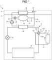
- FIG. 1 is a circuit diagram illustrating an air conditioner 1 according to a first embodiment.
- the air conditioner 1 includes an outdoor machine 2 and an indoor machine 3.
- the outdoor machine 2 is installed out of doors.
- the indoor machine 3 is installed inside a room that is to be cooled or heated using the air conditioner 1.
- the air conditioner 1 further includes a refrigerant circuit 5 and a water circuit 6.
- the refrigerant circuit 5 has a flow path formed therein for the purpose of circulating a refrigerant.
- the water circuit 6 has a flow path formed therein for the purpose of circulating a heating medium (in the following explanation, water) serving as another refrigerant.
- the heating medium circulated in the water circuit 6 can be an antifreeze liquid.
- the refrigerant circuit 5 is disposed inside the outdoor machine 2.
- the refrigerant circuit 5 includes a compressor 11, a four-way valve 12, an outdoor heat exchanger 14, an expansion valve 15, and an intermediate heat exchanger 16.
- the compressor 11 includes a suction pipe 17 and a discharge pipe 18. According to the compressor rotation frequency thereof, the compressor 11 compresses a low-pressure gas-phase refrigerant, which is supplied through the suction pipe 17, and discharges a high-pressure gas-phase refrigerant, which is generated as a result of compressing the low-pressure gas-phase refrigerant, through the discharge pipe 18.
- the four-way valve 12 includes a first connecting port 121, a second connecting port 122, a third connecting port 123, and a fourth connecting port 124.
- the first connecting port 121 is connected to the compressor 11 via the suction pipe 17.
- the second connecting port 122 is connected to the compressor 11 via the discharge pipe 18.
- the third connecting port 123 is connected to the outdoor heat exchanger 14.
- the fourth connecting port 124 is connected to the intermediate heat exchanger 16.
- the four-way valve 12 is switchable to one of the two modes, namely, a cooling mode and a heating mode. When the four-way valve 12 is switched to the heating mode, the second connecting port 122 is connected to the fourth connecting port 124, and the third connecting port 123 is connected to the first connecting port 121.
- the second connecting port 122 is connected to the third connecting port 123, and the fourth connecting port 124 is connected to the first connecting port 121.
- the outdoor heat exchanger 14 is connected to the expansion valve 15.
- the intermediate heat exchanger 16 is also connected to the expansion valve 15.
- the water circuit 6 includes a pump 21 and an indoor heat exchanger 22.
- the pump 21 is disposed inside the outdoor machine 2. Moreover, the pump 21 is connected to the intermediate heat exchanger 16 and the indoor heat exchanger 22.
- the pump 21 supplies the water, which is supplied thereto from the intermediate heat exchanger 16, to the indoor heat exchanger 22, and thus circulates the water in the water circuit 6.
- the indoor heat exchanger 22 is disposed inside the indoor machine 3. Moreover, the indoor heat exchanger 22 is connected to the intermediate heat exchanger 16.
- the air conditioner 1 further includes a heat accumulation circuit 31 that is disposed inside the outdoor machine 2.
- a heat accumulation flow path 32 is formed. Via the heat accumulation flow path 32, a first flow path 33 that is formed between the pump 21 and the indoor heat exchanger 22 of the water circuit 6 is connected to a second flow path 34 that is formed between the indoor heat exchanger 22 and the intermediate heat exchanger 16 of the water circuit 6.
- the heat accumulation circuit 31 includes a heat accumulating unit 35 and a heat accumulation circuit valve 36.
- the heat accumulating unit 35 is made of a material having a higher degree of specific heat as compared to the water.
- the heat accumulating unit 35 is used to store the water flowing through the heat accumulation flow path 32.
- the heat accumulation circuit valve 36 is opened in order to ensure that the first flow path 33 and the second flow path 34 are connected, and is closed in order to ensure that the first flow path 33 and the second flow path 34 are not connected.
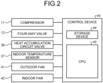
- FIG. 2 is a block diagram illustrating the air conditioner 1 according to the first embodiment.
- the air conditioner 1 includes an outdoor fan 41, an indoor fan 42, and a control device 43.
- the outdoor fan 41 is disposed inside the outdoor machine 2.
- the outdoor fan 41 is controlled by the control device 43 and blows the outside air so as to cause heat exchange between the outdoor heat exchanger 14 and the outside air.
- the indoor fan 42 is disposed inside the indoor machine 3.
- the indoor fan 42 is controlled by the control device 43 and blows the indoor air so as to cause heat exchange between the indoor heat exchanger 22 and the indoor air and to ensure that the indoor air having been subjected to heat exchange with the indoor heat exchanger 22 blows out from the indoor machine 3 into the room.
- the control device 43 is a computer that includes a storage device 44 and a CPU 45 (Central Processing Unit).
- the storage device 44 is used to store computer programs to be installed in the control device 43, and to store the information to be used by the CPU 45.
- the CPU 45 executes the computer programs installed in the control device 43, and accordingly performs information processing and controls the storage device 44.
- the control device 43 controls the compressor 11, the four-way valve 12, the heat accumulation circuit valve 36, the outdoor fan 41, and the indoor fan 42.
- the storage device 44 is used to store the minimum rotation frequency, the rotation frequency threshold value, and the threshold time period.
- the minimum rotation frequency represents a value specific to the compressor 11; and the compressor 11 is not capable of operating at a compressor rotation frequency lower than the minimum rotation frequency.
- the rotation frequency threshold value represents a value specific to the compressor 11 and indicates the minimum rotation frequency for the range in which the operating efficiency of the compressor 11 is equal to or greater than 80%.
- the indoor machine 3 includes an indoor temperature sensor 37 for detecting the indoor temperature.
- the operations performed by the air conditioner 1 include a cooling operation, a heating operation, a heat accumulation operation, and a defrosting operation.
- the cooling operation is performed when, for example, the air conditioner 1 is operated by a user.
- the control device 43 controls the four-way valve 12 and switches the mode thereof to the cooling mode. Then, based on the temperature difference between the set temperature, which is set by the user, and the indoor temperature detected by the indoor temperature sensor 37, the control device 43 calculates the rotation frequency of the compressor 11 and controls the compressor 11 to operate at the calculated rotation frequency; so that the low-pressure gas-phase refrigerant supplied via the suction pipe 17 is compressed.
- the low-pressure gas-phase refrigerant changes the state to the high-pressure gas-phase refrigerant.
- the compressor 11 discharges the high-pressure gas-phase refrigerant to the discharge pipe 18. Since the four-way valve 12 is switched to the cooling mode, the high-pressure gas-phase refrigerant discharged from the discharge pipe 18 is supplied to the outdoor heat exchanger 14.
- the control device 43 controls the outdoor fan 41 that blows the outside air so as to cause heat exchange of the outside air with the outdoor heat exchanger 14.
- the outdoor heat exchanger 14 causes heat exchange between the high-pressure gas-phase refrigerant, which is supplied from the four-way valve 12, and the outside air; so that the high-pressure gas-phase refrigerant is cooled and the outside air is heated.
- the high-pressure gas-phase refrigerant changes the state to the supercooled high-pressure gas-phase refrigerant. That is, when the cooling operation is performed in the air conditioner 1, the outdoor heat exchanger 14 functions as a condensing appliance.
- the high-pressure gas-phase refrigerant that flows out of the outdoor heat exchanger 14 is supplied to the expansion valve 15.
- the expansion valve 15 adjusts the flow rate of the refrigerant flowing out from the outdoor heat exchanger 14 to the intermediate heat exchanger 16, and reduces the pressure of the high-pressure gas-phase refrigerant that is supplied from the outdoor heat exchanger 14. As a result of pressure reduction, the high-pressure gas-phase refrigerant changes the state to the low-pressure gas-liquid two-phase refrigerant having a high degree of humidity wetness. The low-pressure gas-liquid two-phase refrigerant flowing out from the expansion valve 15 is then supplied to the intermediate heat exchanger 16.
- the intermediate heat exchanger 16 causes heat exchange between the low-pressure gas-liquid two-phase refrigerant, which flows out from the expansion valve 15, and the water circulating through the water circuit 6; so that the water is cooled and the low-pressure gas-liquid two-phase refrigerant is heated.
- the low-pressure gas-liquid two-phase refrigerant changes the state to the low-pressure gas-phase refrigerant. That is, when the cooling operation is performed in the air conditioner 1, the intermediate heat exchanger 16 functions as an evaporator.
- the low-pressure gas-phase refrigerant that flows out from the intermediate heat exchanger 16 is then supplied to the four-way valve 12. Since the four-way valve 12 is switched to the cooling mode, the low-pressure gas-phase refrigerant supplied thereto is further supplied to the compressor 11 via the suction pipe 17.
- the control device 43 controls the heat accumulation circuit valve 36 and blocks the heat accumulation flow path 32 in such a way that the water does not flow through the heat accumulation flow path 32. That is done to prevent a situation in which the heat accumulation circuit valve 36 is opened and the water stored in the heat accumulating unit 35 circulates through the water circuit 6. If the water stored in the heat accumulating unit 35 circulates through the water circuit 6, then the heat capacity of the water circuit 6 increases and hence the temperature of the water that is allowed to flow into the indoor heat exchanger 22 does not easily drop. Since the pump 21 circulates the water in the water circuit 6, the water cooled by the intermediate heat exchanger 16 is supplied to the indoor heat exchanger 22.
- the indoor heat exchanger 22 causes heat exchange between the water supplied from the pump 21 and the indoor air in the room in which the indoor machine 3 is installed; so that the water is heated and the indoor air is cooled.
- the heated water circulates through the water circuit 6 and is supplied to the intermediate heat exchanger 16.
- the control device 43 controls the indoor fan 42 that blows the indoor air so as to cause heat exchange of the indoor air with the indoor heat exchanger 22 and that the indoor air cooled by the indoor heat exchanger 22 is blown out into the room. That is, in the indoor machine 3, the indoor heat exchanger 22 cools the indoor air, so that the room becomes cool.
- the heating operation is performed when, for example, the air conditioner 1 is operated by a user.
- the control device 43 switches the four-way valve 12 to the heating mode.
- the control device 43 calculates the rotation frequency of the compressor 11 and controls the compressor 11 to operate at the calculated rotation frequency; so that the low-pressure gas-phase refrigerant supplied via the suction pipe 17 is compressed.
- the low-pressure gas-phase refrigerant changes the state to the high-pressure gas-phase refrigerant.
- the compressor 11 discharges the high-pressure gas-phase refrigerant to the discharge pipe 18. Since the four-way valve 12 is switched to the heating mode, the high-pressure gas-phase refrigerant discharged from the discharge pipe 18 is supplied to the intermediate heat exchanger 16.
- the intermediate heat exchanger 16 causes heat exchange between the high-pressure gas-phase refrigerant, which flows out from the four-way valve 12, and the water circulating through the water circuit 6; so that the water is heated and the high-pressure gas-phase refrigerant is cooled.
- the high-pressure gas-phase refrigerant changes the state to the supercooled high-pressure gas-phase refrigerant. That is, when the heating operation is performed in the air conditioner 1, the intermediate heat exchanger 16 functions as a condensing appliance.
- the high-pressure gas-phase refrigerant that flows out of the intermediate heat exchanger 16 is supplied to the expansion valve 15.
- the expansion valve 15 adjusts the flow rate of the refrigerant flowing out from the intermediate heat exchanger 16 to the outdoor heat exchanger 14, and reduces the pressure of the high-pressure gas-phase refrigerant that is supplied from the outdoor heat exchanger 14. As a result of pressure reduction, the high-pressure gas-phase refrigerant changes the state to the low-pressure gas-liquid two-phase refrigerant having a high degree of humidity wetness. The low-pressure gas-liquid two-phase refrigerant flowing out from the expansion valve 15 is supplied to the outdoor heat exchanger 14.
- the control device 43 controls the outdoor fan 41 that blows the outside air so as to cause heat exchange of the outside air with the outdoor heat exchanger 14.
- the outdoor heat exchanger 14 causes heat exchange between the low-pressure gas-liquid two-phase refrigerant, which is supplied from the expansion valve 15, and the outside air; so that the low-pressure gas-liquid two-phase refrigerant is heated and the outside air is cooled.
- the low-pressure gas-liquid two-phase refrigerant changes the state to the low-pressure gas-phase refrigerant having a low degree of humidity wetness. That is, when the heating operation is performed in the air conditioner 1, the outdoor heat exchanger 14 functions as a condensing appliance.
- the low-pressure gas-phase refrigerant that flows out from the outdoor heat exchanger 14 is supplied to the four-way valve 12. Since the four-way valve 12 is switched to the heating mode, the low-pressure gas-phase refrigerant that flows out from the outdoor heat exchanger 14 is supplied to the suction pipe 17, and is then supplied to the compressor 11 via the suction pipe 17.
- the control device 43 controls the heat accumulation circuit valve 36 and blocks the heat accumulation flow path 32 in such a way that the water does not flow through the heat accumulation flow path 32. That is done to prevent a situation in which the heat accumulation circuit valve 36 is opened and the water stored in the heat accumulating unit 35 circulates through the water circuit 6. If the water stored in the heat accumulating unit 35 circulates through the water circuit 6, then the heat capacity of the water circuit 6 increases and hence the temperature of the water that is allowed to flow into the indoor heat exchanger 22 does not easily rise. Since the pump 21 circulates the water in the water circuit 6, the water that is heated by the intermediate heat exchanger 16 is supplied to the indoor heat exchanger 22.
- the indoor heat exchanger 22 When heat exchange occurs between the water supplied from the pump 21 and the indoor air in the room inside which the indoor machine 3 is installed, the indoor heat exchanger 22 cools the water and heats the indoor air. Then, the heated water circulates through the water circuit 6 and is supplied to the intermediate heat exchanger 16.
- the control device 43 controls the indoor fan 42 that blows the indoor air so as to cause heat exchange of the indoor air with the indoor heat exchanger 22 and to ensure that the air heated by the indoor heat exchanger 22 is blown into the room. That is, in the indoor machine 3, the indoor air is heated by the heat supplied from the outdoor machine 2, so that the room becomes warm.
- the heat accumulation circuit 31 does not accumulate the heat of the water in the heat accumulating unit 35.
- the heat accumulation circuit 31 does not accumulate heat, during the heating operation, there is no unnecessary power consumption for the purpose of heat accumulation, thereby enabling achieving reduction in the power consumption.
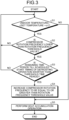
- FIG. 3 is a flowchart for explaining the operation for determining whether or not the heat accumulation operation can be performed.
- the storage device 44 is intermittently used to store the rotation frequency demanded from the compressor 11 (in the following explanation, referred to as the demanded rotation frequency), which is set in advance according to the temperature difference between the set temperature set by the user and the indoor temperature.
- the demanded rotation frequency represents the increase-decrease value of the rotation frequency demanded from the compressor 11 and set in advance according to the temperature difference.
- the demanded rotation frequency increases in proportion to the temperature difference.
- the control device 43 determines whether or not the indoor temperature detected by the indoor temperature sensor 37 is equal to or lower than the set temperature. More particularly, the control device 43 determines whether or not the indoor temperature detected by the indoor temperature sensor 37 is lower than (the set temperature + ⁇ °C) (i.e., lower than a positive value such as 0.5°C) (Step S1).
- the control device 43 determines whether or not the indoor temperature detected by the indoor temperature sensor 37 is lower than (the set temperature + ⁇ °C) (i.e., lower than a positive value such as 0.5°C) (Step S1).
- ⁇ is set to a smaller value (for example, an arbitrary value equal to or greater than 0.1°C and lower than 1.5°C).
- the thermo-off condition implies that the heating operation is stopped until the indoor temperature again drops below the set temperature.
- Step S1 If the indoor temperature is lower than the (the set temperature + ⁇ °C) (Yes at Step S1), then the control device 43 maintains the control of the compressor 11 for compressing the low-pressure gas-phase refrigerant according to the demanded rotation frequency.
- the control device 43 determines whether or not the rotation frequency of the compressor 11 is lower than the rotation frequency threshold value recorded in the storage device 44 (Step S2). If the rotation frequency of the compressor 11 is equal to or greater than the rotation frequency threshold value (No at Step S2), then the operations at Steps S1 and S2 are performed in a repeated manner.
- the rotation frequency threshold value represents a value specific to the compressor 11 and indicates the minimum rotation frequency for the range in which the operating efficiency of the compressor 11 is equal to or greater than 80%. That is, when the compressor 11 compresses the low-pressure gas-phase refrigerant at a rotation frequency lower than the rotation frequency threshold value, the efficiency is lower than the efficiency at the time when the compressor 11 compresses the low-pressure gas-phase refrigerant at the rotation frequency equal to the rotation frequency threshold value. Meanwhile, the rotation frequency threshold value is greater than the minimum rotation frequency.
- the indoor machine 3 includes the indoor temperature sensor 37 for detecting the indoor temperature.
- the control device 43 determines whether or not the remaining time period till the scheduled start timing of the defrosting operation is shorter than a threshold time period (for example, five minutes) that is recorded in the storage device 44 (Step S3).
- the scheduled start timing of the defrosting operation indicates the timing arriving after the elapse of a predetermined period of time since the timing at which the heating operation was started under a predetermined condition.
- Step S3 If the remaining time period is equal to or longer than the threshold time period (No at Step S3), then the control device 43 controls the compressor 11 to ensure that the low-pressure gas-phase refrigerant is compressed according to the demanded rotation frequency, and performs the operations from Step S1 to Step S3 in a repeated manner. Meanwhile, if the rotation frequency of the compressor 11 is lower than the rotation frequency threshold value (Yes at Step S2) and if the remaining time period is shorter than the threshold time period (Yes at Step S3), then the control device 43 controls the compressor 11 and increases the rotation frequency of the compressor 11 to be equal to or greater than the rotation frequency threshold value (Step S4).
- Step S5 the control device 43 controls the heat accumulation circuit valve 36 and opens it to enable the flow of the water through the heat accumulation flow path 32.
- the control device 43 controls the heat accumulation circuit valve 36 and opens it to enable the flow of the water through the heat accumulation flow path 32.
- the heat accumulation circuit 31 causes heat exchange of the water, which is supplied from the pump 21, with the heat accumulating unit 35; so that the heat accumulating unit 35 is heated and the water is cooled. That is, in the air conditioner 1, during the heat accumulation operation, the heat of the water is accumulated in the heat accumulating unit 35, and the heat of the refrigerant is accumulated in the heat accumulating unit 35 via the water.
- the heat accumulation operation is not performed. That enables holding down a situation in which performing the heat accumulation operation promotes frosting on the outdoor heat exchanger 14. Moreover, the surplus electric power is converted into heat for accumulation purposes, and then the accumulated heat is used during the defrosting operation. That enables cutting down on unnecessary power consumption and enhancing the energy saving performance. Furthermore, in the air conditioner 1, during the heat accumulation operation, the compressor 11 compresses the refrigerant at the rotation frequency equal to or greater than the rotation frequency threshold value. Hence, the heat accumulation operation can be performed in the state in which the compressor 11 is driven at such a rotation frequency which enables excellent operating efficiency. Moreover, in the air conditioner 1, since the heat accumulation operation is performed when the indoor temperature is equal to or greater than (the set temperature + ⁇ °C), the surplus heat can be accumulated in the heat accumulation circuit 31 and the accumulated heat can be used during the defrosting operation.
- the defrosting operation is performed.
- the control device 43 controls the four-way valve 12 and switches the mode thereof to the cooling mode. Then, the control device 43 controls the compressor 11 so that the low-pressure gas-phase refrigerant, which is supplied via the suction pipe 17, is compressed at a predetermined rotation frequency. When compressed by the compressor 11, the low-pressure gas-phase refrigerant changes the state to the high-pressure gas-phase refrigerant. Then, the compressor 11 discharges the high-pressure gas-phase refrigerant to the discharge pipe 18. Since the four-way valve 12 is switched to the cooling mode, the high-pressure gas phase refrigerant discharged to the discharge pipe 18 is supplied to the outdoor heat exchanger 14.
- the control device 43 controls the outdoor fan 41 and stops it to ensure that the outside air is not blown in.
- the outdoor heat exchanger 14 causes heat exchange between the high-pressure gas-phase refrigerant, which is supplied from the four-way valve 12, and the frost formed on the outdoor heat exchanger 14; so that the high-pressure gas-phase refrigerant is cooled and the frost formed on the outdoor heat exchanger 14 is heated.
- the high-pressure gas-phase refrigerant changes the state to the supercooled high-pressure gas-phase refrigerant. That is, when the defrosting operation is performed in the air conditioner 1, the outdoor heat exchanger 14 functions as a condensing appliance.
- the heated frost melts and drops down from the outdoor heat exchanger 14.
- the outdoor heat exchanger 14 can be defrosted.
- the outdoor heat exchanger 14 supplies the high-pressure gas-phase refrigerant to the expansion valve 15.
- the expansion valve 15 adjusts the flow rate of the refrigerant flowing out from the outdoor heat exchanger 14 to the intermediate heat exchanger 16, and causes expansion of the high-pressure gas-phase refrigerant that is supplied from the outdoor heat exchanger 14. As a result of expansion, the high-pressure gas-phase refrigerant changes the state to the low-pressure gas-liquid two-phase refrigerant having a high degree of humidity wetness. The low-pressure gas-liquid two-phase refrigerant flowing out from the expansion valve 15 is then supplied to the intermediate heat exchanger 16.
- the intermediate heat exchanger 16 causes heat exchange between the low-pressure gas-liquid two-phase refrigerant, which is supplied from the expansion valve 15, and the water circulating through the water circuit 6; so that the water is cooled and the low-pressure gas-liquid two-phase refrigerant is heated.
- the low-pressure gas-liquid two-phase refrigerant changes the state to the low-pressure gas-phase refrigerant. That is, when the defrosting operation is performed in the air conditioner 1, the intermediate heat exchanger 16 functions as an evaporator. Then, the intermediate heat exchanger 16 supplies the low-pressure gas-phase refrigerant to the four-way valve 12. Since the four-way valve 12 is switched to the cooling mode, the low-pressure gas-phase refrigerant, which is supplied from the intermediate heat exchanger 16, is supplied to the compressor 11 via the suction pipe 17.
- the control device 43 controls the heat accumulation circuit valve 36 and opens it to enable the flow of the water through the heat accumulation flow path 32.
- the pump 21 supplies the water, which is supplied from the intermediate heat exchanger 16, to the indoor heat exchanger 22 and the heat accumulation circuit 31, and thus circulates the water through the water circuit 6.
- the indoor heat exchanger 22 causes heat exchange of the water, which is supplied from the pump 21, with the indoor heat exchanger 22; so that the water is heated and the indoor heat exchanger 22 is cooled.
- the control device 43 controls the indoor fan 42 and stops it to ensure that the air is not blown into the room from the indoor machine 3.
- the heat accumulation circuit 31 Since the heat accumulation circuit valve 36 is opened, the heat accumulation circuit 31 causes heat exchange of the water, which is supplied from the pump 21, with the heat accumulating unit 35; so that the heat accumulating unit 35 is cooled and the water is heated. That is, during the defrosting operation, the heat accumulation circuit 31 heats the water using the heat accumulated in the heat accumulating unit 35.
- the water heated by the indoor heat exchanger 22 or the heat accumulation circuit 31 is circulated in the water circuit 6 by the pump 21 and is then supplied to the intermediate heat exchanger 16.
- the outdoor heat exchanger 14 can be heated using the heat accumulated in the heat accumulating unit 35; so that defrosting of the outdoor heat exchanger 14 can be done using the heat accumulated in the heat accumulating unit 35.
- the amount of heat to be obtained from the indoor air for the purpose of heating the outdoor heat exchanger 14 can be reduced, thereby making it possible to heat the outdoor heat exchanger 14 without excessively cooling the indoor heat exchanger 22.
- a decline in the comfort level during the defrosting operation can be held down by ensuring that the room is not excessively cooled.
- the air conditioner 1 includes the compressor 11, the indoor machine 3, the control device 43, and the heat accumulation circuit 31.
- the compressor 11 circulates the refrigerant in the refrigerant circuit 5.
- the indoor machine 3 heats the inside of the room using the heat of the refrigerant that is supplied to the indoor heat exchanger 22.
- the heat accumulation circuit 31 heats the heat accumulating unit 35 using the heat of the refrigerant.
- the air conditioner 1 when the compressor 11 operates at the minimum rotation frequency and when the indoor temperature exceeds the set temperature (i.e., becomes equal to or greater than (the set temperature + ⁇ °C)), the generated heat is accumulated in the heat accumulating unit 35; so that a decline in the comfort level can be held down by ensuring that the room is not excessively heated. In the air conditioner 1, as a result of effectively using the heat accumulated in the heat accumulating unit 35, it becomes possible to reduce the power consumption.
- the heat accumulation circuit 31 heats the refrigerant using the heat accumulated in the heat accumulating unit 35.
- the heat accumulated in the heat accumulating unit 35 is used in the defrosting operation, it becomes possible to hold down a drop in the indoor temperature during the defrosting operation.
- the control device 43 controls the compressor 11 in such a way that the compressor rotation frequency becomes equal to the demanded rotation frequency. If the remaining time period is shorter than the threshold time period, then the control device 43 controls the compressor 11 in such a way that the compressor rotation frequency becomes higher than the present rotation frequency, and heats the heat accumulating unit 35 using the heat of the refrigerant. In the air conditioner 1 according to the first embodiment, when the remaining time period till the start of the defrosting operation is equal to or longer than the threshold time period, the compressor rotation frequency is not increased to ensure that frost formation on the outdoor heat exchanger 14 is not promoted.
- the compressor rotation frequency is increased to be higher than the present rotation frequency.
- the heat accumulation circuit 31 when the present rotation frequency of the compressor 11 is equal to or greater than the rotation frequency threshold value, the heat accumulation circuit 31 continues the heating operation using the heat of the refrigerant and without heating the heat accumulating unit 35.
- the heat accumulation circuit 31 controls the compressor 11 in such a way that the compressor rotation frequency becomes equal to or higher than the rotation frequency threshold value, and then heats the heat accumulating unit 35 using the heat of the refrigerant.
- the compressor 11 becomes able to operate with excellent operating efficiency.
- the compressor rotation frequency of the compressor 11 when the rotation frequency of the compressor 11 is equal to or lower than the rotation frequency threshold value, that is, when the compressor 11 is operating with excellent operating efficiency, the compressor rotation frequency is not increased. However, when the operating efficiency is low, the compressor rotation frequency is increased to be equal to or higher than the rotation frequency threshold value, and then the heat accumulation operation is performed.
- the heat accumulating unit 35 accumulates heat by means of heat exchange with the water flowing through the heat accumulation flow path 32.
- the heat accumulating unit 35 can be replaced with a hot-water tank used for water storage.
- the hot-water tank In the hot-water tank, the water is stored and, when the heat accumulation circuit valve 36 is opened, the stored water is replaced with the water supplied from the pump 21. That is, when the heat accumulation circuit valve 36 is opened, the heated water is stored in the hot-water tank, thereby enabling accumulation of the heat of the water.
- the heat accumulation circuit valve 36 is opened, the hot water stored in the hot-water tank is supplied to the intermediate heat exchanger 16, so that the accumulated heat can be used in air heating. In the air conditioner 1, even when such a hot-water tank is used, it becomes possible to hold down a decline in the comfort level, while cutting down on power consumption and enhancing the energy saving performance in an identical manner to the air conditioner 1 according to the first embodiment.
- the heat accumulation circuit valve 36 is used to ensure that the water either flows or does not flow through the heat accumulation flow path 32.
- an on-off valve can be further installed.
- the control device 43 controls the on-off valve to ensure that the water flows through the indoor heat exchanger 22.
- the control device 43 controls the on-off valve to ensure that the water does not flow through the indoor heat exchanger 22. In the air conditioner 1, even when such an on-off valve is used, it becomes possible to hold down a decline in the comfort level, while cutting down on power consumption and enhancing the energy saving performance in an identical manner to the air conditioner 1 according to the first embodiment.
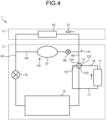
- FIG. 4 is a circuit diagram illustrating an air conditioner according to a second embodiment.
- the water circuit 6 included in the air conditioner 1 according to the first embodiment is omitted, and the refrigerant circuit 5 is replaced with another refrigerant circuit 61.
- an indoor heat exchanger 62 is substituted for the intermediate heat exchanger 16 of the refrigerant circuit 5 of the air conditioner 1 according to the first embodiment.
- the refrigerant circuit 61 is same as the refrigerant circuit 5.
- the indoor heat exchanger 62 is disposed inside the indoor machine 3.
- the indoor fan 42 blows the indoor air so that heat exchange of the indoor air occurs with the indoor heat exchanger 62, and the indoor air having been subjected to heat exchange in the indoor heat exchanger 62 blows into the room from the indoor machine 3.
- the air conditioner according to the second embodiment further includes a heat accumulation circuit 63 that is disposed inside the outdoor machine 2.
- a heat accumulation flow path 64 is formed.
- a first flow path 65 that is formed between the pump 21 and the indoor heat exchanger 22 is connected via the heat accumulation flow path 64 to a second flow path 66 that is formed between the indoor heat exchanger 22 and the intermediate heat exchanger 16.
- the heat accumulation circuit 63 includes a heat accumulating unit 67 and a heat accumulation circuit valve 68.
- the heat accumulating unit 67 is made of a material having a higher degree of specific heat as compared to the water.
- the heat accumulating unit 67 causes heat exchange with the water flowing through the heat accumulation flow path 64.
- the heat accumulation circuit valve 68 is opened in order to ensure that the first flow path 65 and the second flow path 66 are connected, and is closed in order to ensure that the first flow path 65 and the second flow path 66 are not connected.
- the control device 43 controls the compressor 11, the four-way valve 12, the outdoor fan 41, and the indoor fan 42; as well as controls the heat accumulation circuit valve 68 in an identical manner to controlling the heat accumulation circuit valve 36 of the air conditioner 1 according to the first embodiment. That is, when the cooling operation or the heating operation is performed in the air conditioner, the control device 43 controls the heat accumulation circuit valve 68 and blocks the heat accumulation flow path 64 in such a way that the water does not flow through the heat accumulation flow path 32.
- the control device 43 controls the heat accumulation circuit valve 68 and opens the heat accumulation flow path 64 in such a way that the water flows through the heat accumulation flow path 32.
- the heat accumulation is not performed.
- the surplus electric power is converted into heat for accumulation purposes, and then the accumulated heat is used during the defrosting operation. That enables cutting down on unnecessary power consumption and enhancing the energy saving performance.
- the compressor 11 compresses the refrigerant at the rotation frequency equal to or greater than the rotation frequency threshold value.
- the heat accumulation operation can be performed in the state in which the compressor 11 is driven at such a rotation frequency which enables excellent operating efficiency.
- the heat accumulation operation is performed when the indoor temperature is equal to or greater than (the set temperature + ⁇ °C)
- the surplus heat can be accumulated in the heat accumulation circuit 31 and the accumulated heat can be used during the defrosting operation.
- the control device 43 controls the heat accumulation circuit valve 68 and opens the heat accumulation flow path 64 in such a way that the water flows through the heat accumulation flow path 32.
- the outdoor heat exchanger 14 can be heated using the heat accumulated in the heat accumulating unit 67, so that defrosting of the outdoor heat exchanger 14 can be done using the heat accumulated in the heat accumulating unit 67.
- the outdoor heat exchanger 14 is heated using the heat accumulated in the heat accumulating unit 67, in an identical manner to the air conditioner 1 according to the first embodiment, defrosting of the outdoor heat exchanger 14 can be appropriately done without excessively cooling the indoor heat exchanger 22.
- the refrigerant does not pass through the inside of the room.
- the air conditioner according to the second embodiment it is possible to reduce the risk of leakage of the refrigerant into the room.
- the heat accumulation circuit 63 uses the heat accumulation circuit valve 68 to ensure that the refrigerant either flows or does not flow through the heat accumulation flow path 64.
- an on-off valve can be further installed.
- the control device 43 controls the on-off valve to ensure that the refrigerant flows through the indoor heat exchanger 22.
- the control device 43 controls the on-off valve to ensure that the water does not flow through the indoor heat exchanger 22. In the air conditioner, even when such an on-off valve is used, it becomes possible to cut down on power consumption, while holding down a decline in the comfort level in an identical manner to the air conditioner according to the second embodiment.
Landscapes
- Engineering & Computer Science (AREA)
- Mechanical Engineering (AREA)
- General Engineering & Computer Science (AREA)
- Physics & Mathematics (AREA)
- Chemical & Material Sciences (AREA)
- Combustion & Propulsion (AREA)
- Thermal Sciences (AREA)
- Signal Processing (AREA)
- Fuzzy Systems (AREA)
- Mathematical Physics (AREA)
- Air Conditioning Control Device (AREA)
Abstract
Description
- The technology disclosed herein relates to an air conditioner.
- A regenerative air conditioner is known in which a heat accumulation tank is provided in a refrigerant circuit and in which, in the case in which the compressor rotation frequency drops to a low rotation frequency having poor operating efficiency as a result of lowering the air-conditioning capacity needed during the heating operation, the compressor rotation frequency is increased and the heat of the refrigerant that becomes surplus as a result of increasing the compressor rotation frequency (i.e., the surplus heat) is accumulated in the heat accumulation tank (refer to Patent Literature 1). Such a regenerative air conditioner makes use of the heat that is accumulated during, for example, the defrosting operation in which the outdoor heat exchanger is heated. Thus, the electric power that is consumed as a result of increasing the compressor rotation frequency with the aim of improving the operating efficiency of the compressor is converted into heat for accumulation purposes, and then the accumulated heat is used during the defrosting operation. That enables cutting down on unnecessary power consumption and enhancing the energy saving performance.
- [Patent Literature 1]
Japanese Laid-open Patent Publication No. 2016-125808 - However, in such a regenerative air conditioner, at the time of accumulating the surplus heat of the refrigerant, the compression rotation frequency remains high and the situation becomes conducive to frost formation due to the cooling of the outdoor heat exchanger. For that reason, sometimes there is an increase in the duration or the frequency of the defrosting operation, thereby leading to longer periods of time for which the heating operation is stopped. That causes a decline in the comfort level of the user. Hence, conventionally, it is difficult to achieve a balance between improving the energy saving performance and holding down a decline in the comfort level.
- The technology disclosed herein has been developed in view of the issues explained above, and it is an objective to provide an air conditioner that is capable of holding down a decline in the comfort level while improving the energy saving performance.
- According to an aspect of an embodiment, an air conditioner includes an outdoor machine that includes a compressor and an outdoor heat exchanger, an indoor machine that includes an indoor heat exchanger and that heats inside of a room using heat supplied from the outdoor machine, an indoor temperature sensor that detects temperature inside the room, a heat accumulation circuit that includes a heat accumulating unit and that accumulates heat, which is generated in the outdoor machine, in the heat accumulating unit, and a control unit, wherein the control unit controls the compressor in such a way that detection value obtained by the indoor temperature sensor becomes equal to set temperature, and, when the compressor operates at minimum rotation frequency and when detection value obtained by the indoor temperature sensor exceeds the set temperature, operates the heat accumulation circuit.
- The air conditioner disclosed herein is capable of holding down a decline in the comfort level while improving the energy saving performance.
-
-
FIG. 1 is a circuit diagram illustrating an air conditioner according to a first embodiment. -
FIG. 2 is a block diagram illustrating the air conditioner according to the first embodiment. -
FIG. 3 is a flowchart for explaining an operation for determining whether or not a heat accumulation operation needs to be performed. -
FIG. 4 is a circuit diagram illustrating an air conditioner according to a second embodiment. - Exemplary embodiments of an air conditioner according to the application concerned are described below in detail. However, the technology disclosed herein is not limited by the embodiments described below. In the following explanation, identical constituent elements are referred to by the same reference numerals, and their explanation is not given repeatedly.
-
FIG. 1 is a circuit diagram illustrating an air conditioner 1 according to a first embodiment. The air conditioner 1 includes anoutdoor machine 2 and anindoor machine 3. Theoutdoor machine 2 is installed out of doors. Theindoor machine 3 is installed inside a room that is to be cooled or heated using the air conditioner 1. The air conditioner 1 further includes arefrigerant circuit 5 and awater circuit 6. Therefrigerant circuit 5 has a flow path formed therein for the purpose of circulating a refrigerant. Thewater circuit 6 has a flow path formed therein for the purpose of circulating a heating medium (in the following explanation, water) serving as another refrigerant. Alternatively, the heating medium circulated in thewater circuit 6 can be an antifreeze liquid. Therefrigerant circuit 5 is disposed inside theoutdoor machine 2. Therefrigerant circuit 5 includes acompressor 11, a four-way valve 12, anoutdoor heat exchanger 14, anexpansion valve 15, and anintermediate heat exchanger 16. - The
compressor 11 includes asuction pipe 17 and adischarge pipe 18. According to the compressor rotation frequency thereof, thecompressor 11 compresses a low-pressure gas-phase refrigerant, which is supplied through thesuction pipe 17, and discharges a high-pressure gas-phase refrigerant, which is generated as a result of compressing the low-pressure gas-phase refrigerant, through thedischarge pipe 18. - The four-
way valve 12 includes a first connectingport 121, a second connectingport 122, a third connectingport 123, and a fourth connectingport 124. The first connectingport 121 is connected to thecompressor 11 via thesuction pipe 17. The second connectingport 122 is connected to thecompressor 11 via thedischarge pipe 18. The third connectingport 123 is connected to theoutdoor heat exchanger 14. The fourth connectingport 124 is connected to theintermediate heat exchanger 16. The four-way valve 12 is switchable to one of the two modes, namely, a cooling mode and a heating mode. When the four-way valve 12 is switched to the heating mode, the second connectingport 122 is connected to the fourth connectingport 124, and the third connectingport 123 is connected to the first connectingport 121. When the four-way valve 12 is switched to the cooling mode, the second connectingport 122 is connected to the third connectingport 123, and the fourth connectingport 124 is connected to the first connectingport 121. - The
outdoor heat exchanger 14 is connected to theexpansion valve 15. Theintermediate heat exchanger 16 is also connected to theexpansion valve 15. - The
water circuit 6 includes apump 21 and anindoor heat exchanger 22. Thepump 21 is disposed inside theoutdoor machine 2. Moreover, thepump 21 is connected to theintermediate heat exchanger 16 and theindoor heat exchanger 22. Thepump 21 supplies the water, which is supplied thereto from theintermediate heat exchanger 16, to theindoor heat exchanger 22, and thus circulates the water in thewater circuit 6. Theindoor heat exchanger 22 is disposed inside theindoor machine 3. Moreover, theindoor heat exchanger 22 is connected to theintermediate heat exchanger 16. - The air conditioner 1 further includes a
heat accumulation circuit 31 that is disposed inside theoutdoor machine 2. In theheat accumulation circuit 31, a heataccumulation flow path 32 is formed. Via the heataccumulation flow path 32, afirst flow path 33 that is formed between thepump 21 and theindoor heat exchanger 22 of thewater circuit 6 is connected to asecond flow path 34 that is formed between theindoor heat exchanger 22 and theintermediate heat exchanger 16 of thewater circuit 6. Theheat accumulation circuit 31 includes aheat accumulating unit 35 and a heataccumulation circuit valve 36. Theheat accumulating unit 35 is made of a material having a higher degree of specific heat as compared to the water. Theheat accumulating unit 35 is used to store the water flowing through the heataccumulation flow path 32. The heataccumulation circuit valve 36 is opened in order to ensure that thefirst flow path 33 and thesecond flow path 34 are connected, and is closed in order to ensure that thefirst flow path 33 and thesecond flow path 34 are not connected. -
FIG. 2 is a block diagram illustrating the air conditioner 1 according to the first embodiment. The air conditioner 1 includes anoutdoor fan 41, anindoor fan 42, and acontrol device 43. Theoutdoor fan 41 is disposed inside theoutdoor machine 2. Theoutdoor fan 41 is controlled by thecontrol device 43 and blows the outside air so as to cause heat exchange between theoutdoor heat exchanger 14 and the outside air. Theindoor fan 42 is disposed inside theindoor machine 3. Theindoor fan 42 is controlled by thecontrol device 43 and blows the indoor air so as to cause heat exchange between theindoor heat exchanger 22 and the indoor air and to ensure that the indoor air having been subjected to heat exchange with theindoor heat exchanger 22 blows out from theindoor machine 3 into the room. - The
control device 43 is a computer that includes astorage device 44 and a CPU 45 (Central Processing Unit). Thestorage device 44 is used to store computer programs to be installed in thecontrol device 43, and to store the information to be used by the CPU 45. The CPU 45 executes the computer programs installed in thecontrol device 43, and accordingly performs information processing and controls thestorage device 44. - The
control device 43 controls thecompressor 11, the four-way valve 12, the heataccumulation circuit valve 36, theoutdoor fan 41, and theindoor fan 42. Thestorage device 44 is used to store the minimum rotation frequency, the rotation frequency threshold value, and the threshold time period. The minimum rotation frequency represents a value specific to thecompressor 11; and thecompressor 11 is not capable of operating at a compressor rotation frequency lower than the minimum rotation frequency. The rotation frequency threshold value represents a value specific to thecompressor 11 and indicates the minimum rotation frequency for the range in which the operating efficiency of thecompressor 11 is equal to or greater than 80%. That is, when thecompressor 11 compresses the low-pressure gas-phase refrigerant at a rotation frequency lower than the rotation frequency threshold value, the efficiency is lower than the efficiency at the time when thecompressor 11 compresses the low-pressure gas-phase refrigerant at the rotation frequency equal to the rotation frequency threshold value. Meanwhile, the rotation frequency threshold value is greater than the minimum rotation frequency. Moreover, theindoor machine 3 includes anindoor temperature sensor 37 for detecting the indoor temperature. - The operations performed by the air conditioner 1 include a cooling operation, a heating operation, a heat accumulation operation, and a defrosting operation.
- The cooling operation is performed when, for example, the air conditioner 1 is operated by a user. When the cooling operation is performed in the air conditioner 1, the
control device 43 controls the four-way valve 12 and switches the mode thereof to the cooling mode. Then, based on the temperature difference between the set temperature, which is set by the user, and the indoor temperature detected by theindoor temperature sensor 37, thecontrol device 43 calculates the rotation frequency of thecompressor 11 and controls thecompressor 11 to operate at the calculated rotation frequency; so that the low-pressure gas-phase refrigerant supplied via thesuction pipe 17 is compressed. When compressed by thecompressor 11, the low-pressure gas-phase refrigerant changes the state to the high-pressure gas-phase refrigerant. Then, thecompressor 11 discharges the high-pressure gas-phase refrigerant to thedischarge pipe 18. Since the four-way valve 12 is switched to the cooling mode, the high-pressure gas-phase refrigerant discharged from thedischarge pipe 18 is supplied to theoutdoor heat exchanger 14. - The
control device 43 controls theoutdoor fan 41 that blows the outside air so as to cause heat exchange of the outside air with theoutdoor heat exchanger 14. Theoutdoor heat exchanger 14 causes heat exchange between the high-pressure gas-phase refrigerant, which is supplied from the four-way valve 12, and the outside air; so that the high-pressure gas-phase refrigerant is cooled and the outside air is heated. When cooled, the high-pressure gas-phase refrigerant changes the state to the supercooled high-pressure gas-phase refrigerant. That is, when the cooling operation is performed in the air conditioner 1, theoutdoor heat exchanger 14 functions as a condensing appliance. The high-pressure gas-phase refrigerant that flows out of theoutdoor heat exchanger 14 is supplied to theexpansion valve 15. - The
expansion valve 15 adjusts the flow rate of the refrigerant flowing out from theoutdoor heat exchanger 14 to theintermediate heat exchanger 16, and reduces the pressure of the high-pressure gas-phase refrigerant that is supplied from theoutdoor heat exchanger 14. As a result of pressure reduction, the high-pressure gas-phase refrigerant changes the state to the low-pressure gas-liquid two-phase refrigerant having a high degree of humidity wetness. The low-pressure gas-liquid two-phase refrigerant flowing out from theexpansion valve 15 is then supplied to theintermediate heat exchanger 16. - During the cooling operation, the
intermediate heat exchanger 16 causes heat exchange between the low-pressure gas-liquid two-phase refrigerant, which flows out from theexpansion valve 15, and the water circulating through thewater circuit 6; so that the water is cooled and the low-pressure gas-liquid two-phase refrigerant is heated. When heated by theintermediate heat exchanger 16, the low-pressure gas-liquid two-phase refrigerant changes the state to the low-pressure gas-phase refrigerant. That is, when the cooling operation is performed in the air conditioner 1, theintermediate heat exchanger 16 functions as an evaporator. The low-pressure gas-phase refrigerant that flows out from theintermediate heat exchanger 16 is then supplied to the four-way valve 12. Since the four-way valve 12 is switched to the cooling mode, the low-pressure gas-phase refrigerant supplied thereto is further supplied to thecompressor 11 via thesuction pipe 17. - When the cooling operation is performed in the air conditioner 1, the
control device 43 controls the heataccumulation circuit valve 36 and blocks the heataccumulation flow path 32 in such a way that the water does not flow through the heataccumulation flow path 32. That is done to prevent a situation in which the heataccumulation circuit valve 36 is opened and the water stored in theheat accumulating unit 35 circulates through thewater circuit 6. If the water stored in theheat accumulating unit 35 circulates through thewater circuit 6, then the heat capacity of thewater circuit 6 increases and hence the temperature of the water that is allowed to flow into theindoor heat exchanger 22 does not easily drop. Since thepump 21 circulates the water in thewater circuit 6, the water cooled by theintermediate heat exchanger 16 is supplied to theindoor heat exchanger 22. Then, theindoor heat exchanger 22 causes heat exchange between the water supplied from thepump 21 and the indoor air in the room in which theindoor machine 3 is installed; so that the water is heated and the indoor air is cooled. The heated water circulates through thewater circuit 6 and is supplied to theintermediate heat exchanger 16. Thecontrol device 43 controls theindoor fan 42 that blows the indoor air so as to cause heat exchange of the indoor air with theindoor heat exchanger 22 and that the indoor air cooled by theindoor heat exchanger 22 is blown out into the room. That is, in theindoor machine 3, theindoor heat exchanger 22 cools the indoor air, so that the room becomes cool. - The heating operation is performed when, for example, the air conditioner 1 is operated by a user. When the heating operation is performed in the air conditioner 1, the
control device 43 switches the four-way valve 12 to the heating mode. Then, based on the set temperature, which is set by the user, and the indoor temperature, thecontrol device 43 calculates the rotation frequency of thecompressor 11 and controls thecompressor 11 to operate at the calculated rotation frequency; so that the low-pressure gas-phase refrigerant supplied via thesuction pipe 17 is compressed. When compressed by thecompressor 11, the low-pressure gas-phase refrigerant changes the state to the high-pressure gas-phase refrigerant. Then, thecompressor 11 discharges the high-pressure gas-phase refrigerant to thedischarge pipe 18. Since the four-way valve 12 is switched to the heating mode, the high-pressure gas-phase refrigerant discharged from thedischarge pipe 18 is supplied to theintermediate heat exchanger 16. - During the heating operation, the
intermediate heat exchanger 16 causes heat exchange between the high-pressure gas-phase refrigerant, which flows out from the four-way valve 12, and the water circulating through thewater circuit 6; so that the water is heated and the high-pressure gas-phase refrigerant is cooled. When cooled by theintermediate heat exchanger 16, the high-pressure gas-phase refrigerant changes the state to the supercooled high-pressure gas-phase refrigerant. That is, when the heating operation is performed in the air conditioner 1, theintermediate heat exchanger 16 functions as a condensing appliance. The high-pressure gas-phase refrigerant that flows out of theintermediate heat exchanger 16 is supplied to theexpansion valve 15. - The
expansion valve 15 adjusts the flow rate of the refrigerant flowing out from theintermediate heat exchanger 16 to theoutdoor heat exchanger 14, and reduces the pressure of the high-pressure gas-phase refrigerant that is supplied from theoutdoor heat exchanger 14. As a result of pressure reduction, the high-pressure gas-phase refrigerant changes the state to the low-pressure gas-liquid two-phase refrigerant having a high degree of humidity wetness. The low-pressure gas-liquid two-phase refrigerant flowing out from theexpansion valve 15 is supplied to theoutdoor heat exchanger 14. - The
control device 43 controls theoutdoor fan 41 that blows the outside air so as to cause heat exchange of the outside air with theoutdoor heat exchanger 14. Theoutdoor heat exchanger 14 causes heat exchange between the low-pressure gas-liquid two-phase refrigerant, which is supplied from theexpansion valve 15, and the outside air; so that the low-pressure gas-liquid two-phase refrigerant is heated and the outside air is cooled. When heated, the low-pressure gas-liquid two-phase refrigerant changes the state to the low-pressure gas-phase refrigerant having a low degree of humidity wetness. That is, when the heating operation is performed in the air conditioner 1, theoutdoor heat exchanger 14 functions as a condensing appliance. The low-pressure gas-phase refrigerant that flows out from theoutdoor heat exchanger 14 is supplied to the four-way valve 12. Since the four-way valve 12 is switched to the heating mode, the low-pressure gas-phase refrigerant that flows out from theoutdoor heat exchanger 14 is supplied to thesuction pipe 17, and is then supplied to thecompressor 11 via thesuction pipe 17. - When the heating operation is performed in the air conditioner 1, the
control device 43 controls the heataccumulation circuit valve 36 and blocks the heataccumulation flow path 32 in such a way that the water does not flow through the heataccumulation flow path 32. That is done to prevent a situation in which the heataccumulation circuit valve 36 is opened and the water stored in theheat accumulating unit 35 circulates through thewater circuit 6. If the water stored in theheat accumulating unit 35 circulates through thewater circuit 6, then the heat capacity of thewater circuit 6 increases and hence the temperature of the water that is allowed to flow into theindoor heat exchanger 22 does not easily rise. Since thepump 21 circulates the water in thewater circuit 6, the water that is heated by theintermediate heat exchanger 16 is supplied to theindoor heat exchanger 22. When heat exchange occurs between the water supplied from thepump 21 and the indoor air in the room inside which theindoor machine 3 is installed, theindoor heat exchanger 22 cools the water and heats the indoor air. Then, the heated water circulates through thewater circuit 6 and is supplied to theintermediate heat exchanger 16. Thecontrol device 43 controls theindoor fan 42 that blows the indoor air so as to cause heat exchange of the indoor air with theindoor heat exchanger 22 and to ensure that the air heated by theindoor heat exchanger 22 is blown into the room. That is, in theindoor machine 3, the indoor air is heated by the heat supplied from theoutdoor machine 2, so that the room becomes warm. - When the heating operation is performed in the air conditioner 1, since the water does not flow through the heat
accumulation flow path 32, theheat accumulation circuit 31 does not accumulate the heat of the water in theheat accumulating unit 35. In the air conditioner 1, since theheat accumulation circuit 31 does not accumulate heat, during the heating operation, there is no unnecessary power consumption for the purpose of heat accumulation, thereby enabling achieving reduction in the power consumption. - While the heating operation is underway, when the
control device 43 determines that the heat accumulation operation can be performed, the heat accumulation operation is performed.FIG. 3 is a flowchart for explaining the operation for determining whether or not the heat accumulation operation can be performed. While the heating operation is underway, thestorage device 44 is intermittently used to store the rotation frequency demanded from the compressor 11 (in the following explanation, referred to as the demanded rotation frequency), which is set in advance according to the temperature difference between the set temperature set by the user and the indoor temperature. The demanded rotation frequency represents the increase-decrease value of the rotation frequency demanded from thecompressor 11 and set in advance according to the temperature difference. Thus, the demanded rotation frequency increases in proportion to the temperature difference. Thecontrol device 43 determines whether or not the indoor temperature detected by theindoor temperature sensor 37 is equal to or lower than the set temperature. More particularly, thecontrol device 43 determines whether or not the indoor temperature detected by theindoor temperature sensor 37 is lower than (the set temperature + α°C) (i.e., lower than a positive value such as 0.5°C) (Step S1). Herein, as compared to the thermo-off condition (for example, 1.5°C) at which thecompressor 11 stops operating, α is set to a smaller value (for example, an arbitrary value equal to or greater than 0.1°C and lower than 1.5°C). The thermo-off condition implies that the heating operation is stopped until the indoor temperature again drops below the set temperature. - If the indoor temperature is lower than the (the set temperature + α°C) (Yes at Step S1), then the
control device 43 maintains the control of thecompressor 11 for compressing the low-pressure gas-phase refrigerant according to the demanded rotation frequency. When the indoor temperature is lower than (the set temperature + α°C), thecontrol device 43 determines whether or not the rotation frequency of thecompressor 11 is lower than the rotation frequency threshold value recorded in the storage device 44 (Step S2). If the rotation frequency of thecompressor 11 is equal to or greater than the rotation frequency threshold value (No at Step S2), then the operations at Steps S1 and S2 are performed in a repeated manner. The rotation frequency threshold value represents a value specific to thecompressor 11 and indicates the minimum rotation frequency for the range in which the operating efficiency of thecompressor 11 is equal to or greater than 80%. That is, when thecompressor 11 compresses the low-pressure gas-phase refrigerant at a rotation frequency lower than the rotation frequency threshold value, the efficiency is lower than the efficiency at the time when thecompressor 11 compresses the low-pressure gas-phase refrigerant at the rotation frequency equal to the rotation frequency threshold value. Meanwhile, the rotation frequency threshold value is greater than the minimum rotation frequency. Moreover, theindoor machine 3 includes theindoor temperature sensor 37 for detecting the indoor temperature. - Meanwhile, if the rotation frequency of the
compressor 11 is lower than the rotation frequency threshold value (Yes at Step S2), then thecontrol device 43 determines whether or not the remaining time period till the scheduled start timing of the defrosting operation is shorter than a threshold time period (for example, five minutes) that is recorded in the storage device 44 (Step S3). The scheduled start timing of the defrosting operation indicates the timing arriving after the elapse of a predetermined period of time since the timing at which the heating operation was started under a predetermined condition. If the remaining time period is equal to or longer than the threshold time period (No at Step S3), then thecontrol device 43 controls thecompressor 11 to ensure that the low-pressure gas-phase refrigerant is compressed according to the demanded rotation frequency, and performs the operations from Step S1 to Step S3 in a repeated manner. Meanwhile, if the rotation frequency of thecompressor 11 is lower than the rotation frequency threshold value (Yes at Step S2) and if the remaining time period is shorter than the threshold time period (Yes at Step S3), then thecontrol device 43 controls thecompressor 11 and increases the rotation frequency of thecompressor 11 to be equal to or greater than the rotation frequency threshold value (Step S4). - Either after increasing the rotation frequency of the
compressor 11 or when the indoor temperature is equal to or higher than (the set temperature + α°C) (No at Step S1), thecontrol device 43 performs the heat accumulation operation in which theheat accumulation circuit 31 is operated (Step S5). That is, thecontrol device 43 controls the heataccumulation circuit valve 36 and opens it to enable the flow of the water through the heataccumulation flow path 32. As a result of increasing the rotation frequency of thecompressor 11, the amount of heat supplied to theindoor heat exchanger 22 becomes excessive with respect to the amount of heat needed for heating. Hence, the surplus heat is accumulated in theheat accumulation circuit 31. As a result of opening the heataccumulation circuit valve 36, theheat accumulation circuit 31 causes heat exchange of the water, which is supplied from thepump 21, with theheat accumulating unit 35; so that theheat accumulating unit 35 is heated and the water is cooled. That is, in the air conditioner 1, during the heat accumulation operation, the heat of the water is accumulated in theheat accumulating unit 35, and the heat of the refrigerant is accumulated in theheat accumulating unit 35 via the water. - In the air conditioner 1, until the remaining time period till starting the defrosting operation becomes shorter than the threshold time period, the heat accumulation operation is not performed. That enables holding down a situation in which performing the heat accumulation operation promotes frosting on the
outdoor heat exchanger 14. Moreover, the surplus electric power is converted into heat for accumulation purposes, and then the accumulated heat is used during the defrosting operation. That enables cutting down on unnecessary power consumption and enhancing the energy saving performance. Furthermore, in the air conditioner 1, during the heat accumulation operation, thecompressor 11 compresses the refrigerant at the rotation frequency equal to or greater than the rotation frequency threshold value. Hence, the heat accumulation operation can be performed in the state in which thecompressor 11 is driven at such a rotation frequency which enables excellent operating efficiency. Moreover, in the air conditioner 1, since the heat accumulation operation is performed when the indoor temperature is equal to or greater than (the set temperature + α°C), the surplus heat can be accumulated in theheat accumulation circuit 31 and the accumulated heat can be used during the defrosting operation. - After the heating operation is performed on a continuous basis under a predetermined condition and for a predetermined period of time or beyond, the defrosting operation is performed. In the air conditioner 1, at the time of performing the defrosting operation, the
control device 43 controls the four-way valve 12 and switches the mode thereof to the cooling mode. Then, thecontrol device 43 controls thecompressor 11 so that the low-pressure gas-phase refrigerant, which is supplied via thesuction pipe 17, is compressed at a predetermined rotation frequency. When compressed by thecompressor 11, the low-pressure gas-phase refrigerant changes the state to the high-pressure gas-phase refrigerant. Then, thecompressor 11 discharges the high-pressure gas-phase refrigerant to thedischarge pipe 18. Since the four-way valve 12 is switched to the cooling mode, the high-pressure gas phase refrigerant discharged to thedischarge pipe 18 is supplied to theoutdoor heat exchanger 14. - The
control device 43 controls theoutdoor fan 41 and stops it to ensure that the outside air is not blown in. Theoutdoor heat exchanger 14 causes heat exchange between the high-pressure gas-phase refrigerant, which is supplied from the four-way valve 12, and the frost formed on theoutdoor heat exchanger 14; so that the high-pressure gas-phase refrigerant is cooled and the frost formed on theoutdoor heat exchanger 14 is heated. When cooled, the high-pressure gas-phase refrigerant changes the state to the supercooled high-pressure gas-phase refrigerant. That is, when the defrosting operation is performed in the air conditioner 1, theoutdoor heat exchanger 14 functions as a condensing appliance. The heated frost melts and drops down from theoutdoor heat exchanger 14. Thus, as a result of performing the defrosting operation in the air conditioner 1, theoutdoor heat exchanger 14 can be defrosted. Moreover, theoutdoor heat exchanger 14 supplies the high-pressure gas-phase refrigerant to theexpansion valve 15. - The
expansion valve 15 adjusts the flow rate of the refrigerant flowing out from theoutdoor heat exchanger 14 to theintermediate heat exchanger 16, and causes expansion of the high-pressure gas-phase refrigerant that is supplied from theoutdoor heat exchanger 14. As a result of expansion, the high-pressure gas-phase refrigerant changes the state to the low-pressure gas-liquid two-phase refrigerant having a high degree of humidity wetness. The low-pressure gas-liquid two-phase refrigerant flowing out from theexpansion valve 15 is then supplied to theintermediate heat exchanger 16. - The
intermediate heat exchanger 16 causes heat exchange between the low-pressure gas-liquid two-phase refrigerant, which is supplied from theexpansion valve 15, and the water circulating through thewater circuit 6; so that the water is cooled and the low-pressure gas-liquid two-phase refrigerant is heated. When heated by theintermediate heat exchanger 16, the low-pressure gas-liquid two-phase refrigerant changes the state to the low-pressure gas-phase refrigerant. That is, when the defrosting operation is performed in the air conditioner 1, theintermediate heat exchanger 16 functions as an evaporator. Then, theintermediate heat exchanger 16 supplies the low-pressure gas-phase refrigerant to the four-way valve 12. Since the four-way valve 12 is switched to the cooling mode, the low-pressure gas-phase refrigerant, which is supplied from theintermediate heat exchanger 16, is supplied to thecompressor 11 via thesuction pipe 17. - When the defrosting operation is performed in the air conditioner 1, the
control device 43 controls the heataccumulation circuit valve 36 and opens it to enable the flow of the water through the heataccumulation flow path 32. Thepump 21 supplies the water, which is supplied from theintermediate heat exchanger 16, to theindoor heat exchanger 22 and theheat accumulation circuit 31, and thus circulates the water through thewater circuit 6. Theindoor heat exchanger 22 causes heat exchange of the water, which is supplied from thepump 21, with theindoor heat exchanger 22; so that the water is heated and theindoor heat exchanger 22 is cooled. Thecontrol device 43 controls theindoor fan 42 and stops it to ensure that the air is not blown into the room from theindoor machine 3. When the defrosting operation is performed in the air conditioner 1, since theindoor fan 42 is stopped, the indoor air can be prevented from being cooled by theindoor heat exchanger 22, and hence a decline in the comfort level can be held down. - Since the heat
accumulation circuit valve 36 is opened, theheat accumulation circuit 31 causes heat exchange of the water, which is supplied from thepump 21, with theheat accumulating unit 35; so that theheat accumulating unit 35 is cooled and the water is heated. That is, during the defrosting operation, theheat accumulation circuit 31 heats the water using the heat accumulated in theheat accumulating unit 35. The water heated by theindoor heat exchanger 22 or theheat accumulation circuit 31 is circulated in thewater circuit 6 by thepump 21 and is then supplied to theintermediate heat exchanger 16. - That is, in the air conditioner 1, during the defrosting operation, the
outdoor heat exchanger 14 can be heated using the heat accumulated in theheat accumulating unit 35; so that defrosting of theoutdoor heat exchanger 14 can be done using the heat accumulated in theheat accumulating unit 35. In the air conditioner 1, since theoutdoor heat exchanger 14 is heated using the heat accumulated in theheat accumulating unit 35, the amount of heat to be obtained from the indoor air for the purpose of heating theoutdoor heat exchanger 14 can be reduced, thereby making it possible to heat theoutdoor heat exchanger 14 without excessively cooling theindoor heat exchanger 22. As a result, a decline in the comfort level during the defrosting operation can be held down by ensuring that the room is not excessively cooled. - The air conditioner 1 according to the first embodiment includes the
compressor 11, theindoor machine 3, thecontrol device 43, and theheat accumulation circuit 31. Thecompressor 11 circulates the refrigerant in therefrigerant circuit 5. Theindoor machine 3 heats the inside of the room using the heat of the refrigerant that is supplied to theindoor heat exchanger 22. When thecompressor 11 operates at the minimum rotation frequency and when the indoor temperature exceeds the set temperature (i.e., becomes equal to or greater than (the set temperature + α°C)), theheat accumulation circuit 31 heats theheat accumulating unit 35 using the heat of the refrigerant. - In the air conditioner 1 according to the first embodiment, when the
compressor 11 operates at the minimum rotation frequency and when the indoor temperature exceeds the set temperature (i.e., becomes equal to or greater than (the set temperature + α°C)), the generated heat is accumulated in theheat accumulating unit 35; so that a decline in the comfort level can be held down by ensuring that the room is not excessively heated. In the air conditioner 1, as a result of effectively using the heat accumulated in theheat accumulating unit 35, it becomes possible to reduce the power consumption. - Moreover, in the air conditioner 1 according to the first embodiment, during the defrosting operation in which a heat exchanger meant for causing heat exchange between the outside air and the refrigerant is heated, the
heat accumulation circuit 31 heats the refrigerant using the heat accumulated in theheat accumulating unit 35. In the air conditioner 1 according to the first embodiment, since the heat accumulated in theheat accumulating unit 35 is used in the defrosting operation, it becomes possible to hold down a drop in the indoor temperature during the defrosting operation. - Furthermore, in the air conditioner 1 according to the first embodiment, when the remaining time period till the start of the defrosting operation is equal to or longer than the predetermined threshold time period, the
control device 43 controls thecompressor 11 in such a way that the compressor rotation frequency becomes equal to the demanded rotation frequency. If the remaining time period is shorter than the threshold time period, then thecontrol device 43 controls thecompressor 11 in such a way that the compressor rotation frequency becomes higher than the present rotation frequency, and heats theheat accumulating unit 35 using the heat of the refrigerant. In the air conditioner 1 according to the first embodiment, when the remaining time period till the start of the defrosting operation is equal to or longer than the threshold time period, the compressor rotation frequency is not increased to ensure that frost formation on theoutdoor heat exchanger 14 is not promoted. In the air conditioner 1 according to the first embodiment, when the remaining time period is shorter than the threshold time period, the compressor rotation frequency is increased to be higher than the present rotation frequency. As a result, while holding down an increase or a decrease in the amount of frost formation attributed to operating the compressor at a high rotation frequency for a long period of time, a large amount of heat can be accumulated before performing the defrosting operation, thereby enabling appropriate defrosting of theoutdoor heat exchanger 14. - Moreover, in the air conditioner 1 according to the first embodiment, when the present rotation frequency of the
compressor 11 is equal to or greater than the rotation frequency threshold value, theheat accumulation circuit 31 continues the heating operation using the heat of the refrigerant and without heating theheat accumulating unit 35. When the present rotation frequency of thecompressor 11 drops below the rotation frequency threshold value, theheat accumulation circuit 31 controls thecompressor 11 in such a way that the compressor rotation frequency becomes equal to or higher than the rotation frequency threshold value, and then heats theheat accumulating unit 35 using the heat of the refrigerant. When the refrigerant is compressed according to the compressor rotation frequency equal to or greater than the rotation frequency threshold value, thecompressor 11 becomes able to operate with excellent operating efficiency. In the air conditioner 1 according to the first embodiment, when the rotation frequency of thecompressor 11 is equal to or lower than the rotation frequency threshold value, that is, when thecompressor 11 is operating with excellent operating efficiency, the compressor rotation frequency is not increased. However, when the operating efficiency is low, the compressor rotation frequency is increased to be equal to or higher than the rotation frequency threshold value, and then the heat accumulation operation is performed. - In the air conditioner 1 according to the first embodiment, the
heat accumulating unit 35 accumulates heat by means of heat exchange with the water flowing through the heataccumulation flow path 32. However, theheat accumulating unit 35 can be replaced with a hot-water tank used for water storage. In the hot-water tank, the water is stored and, when the heataccumulation circuit valve 36 is opened, the stored water is replaced with the water supplied from thepump 21. That is, when the heataccumulation circuit valve 36 is opened, the heated water is stored in the hot-water tank, thereby enabling accumulation of the heat of the water. When the heataccumulation circuit valve 36 is opened, the hot water stored in the hot-water tank is supplied to theintermediate heat exchanger 16, so that the accumulated heat can be used in air heating. In the air conditioner 1, even when such a hot-water tank is used, it becomes possible to hold down a decline in the comfort level, while cutting down on power consumption and enhancing the energy saving performance in an identical manner to the air conditioner 1 according to the first embodiment. - In the air conditioner 1 according to the first embodiment, the heat
accumulation circuit valve 36 is used to ensure that the water either flows or does not flow through the heataccumulation flow path 32. Alternatively, an on-off valve can be further installed. During the cooling operation, or during the heating operation, or during the heat accumulation operation; thecontrol device 43 controls the on-off valve to ensure that the water flows through theindoor heat exchanger 22. During the defrosting operation, thecontrol device 43 controls the on-off valve to ensure that the water does not flow through theindoor heat exchanger 22. In the air conditioner 1, even when such an on-off valve is used, it becomes possible to hold down a decline in the comfort level, while cutting down on power consumption and enhancing the energy saving performance in an identical manner to the air conditioner 1 according to the first embodiment. -
FIG. 4 is a circuit diagram illustrating an air conditioner according to a second embodiment. In the air conditioner according to the second embodiment, thewater circuit 6 included in the air conditioner 1 according to the first embodiment is omitted, and therefrigerant circuit 5 is replaced with anotherrefrigerant circuit 61. In therefrigerant circuit 61, anindoor heat exchanger 62 is substituted for theintermediate heat exchanger 16 of therefrigerant circuit 5 of the air conditioner 1 according to the first embodiment. Apart from that, therefrigerant circuit 61 is same as therefrigerant circuit 5. Theindoor heat exchanger 62 is disposed inside theindoor machine 3. Theindoor fan 42 blows the indoor air so that heat exchange of the indoor air occurs with theindoor heat exchanger 62, and the indoor air having been subjected to heat exchange in theindoor heat exchanger 62 blows into the room from theindoor machine 3. - The air conditioner according to the second embodiment further includes a
heat accumulation circuit 63 that is disposed inside theoutdoor machine 2. In theheat accumulation circuit 63, a heataccumulation flow path 64 is formed. In therefrigerant circuit 61, afirst flow path 65 that is formed between thepump 21 and theindoor heat exchanger 22 is connected via the heataccumulation flow path 64 to asecond flow path 66 that is formed between theindoor heat exchanger 22 and theintermediate heat exchanger 16. Theheat accumulation circuit 63 includes aheat accumulating unit 67 and a heataccumulation circuit valve 68. Theheat accumulating unit 67 is made of a material having a higher degree of specific heat as compared to the water. Theheat accumulating unit 67 causes heat exchange with the water flowing through the heataccumulation flow path 64. The heataccumulation circuit valve 68 is opened in order to ensure that thefirst flow path 65 and thesecond flow path 66 are connected, and is closed in order to ensure that thefirst flow path 65 and thesecond flow path 66 are not connected. - In an identical manner to the air conditioner 1 according to the first embodiment, the
control device 43 controls thecompressor 11, the four-way valve 12, theoutdoor fan 41, and theindoor fan 42; as well as controls the heataccumulation circuit valve 68 in an identical manner to controlling the heataccumulation circuit valve 36 of the air conditioner 1 according to the first embodiment. That is, when the cooling operation or the heating operation is performed in the air conditioner, thecontrol device 43 controls the heataccumulation circuit valve 68 and blocks the heataccumulation flow path 64 in such a way that the water does not flow through the heataccumulation flow path 32. - When the heat accumulation operation is performed in the air conditioner, the
control device 43 controls the heataccumulation circuit valve 68 and opens the heataccumulation flow path 64 in such a way that the water flows through the heataccumulation flow path 32. In the air conditioner, until the remaining time period till the start of the defrosting operation becomes shorter than the threshold time period, the heat accumulation is not performed. Hence, in an identical manner to the air conditioner 1 according to the first embodiment, it becomes possible to hold down a situation in which performing the heat accumulation operation promotes frosting on theoutdoor heat exchanger 14. Moreover, the surplus electric power is converted into heat for accumulation purposes, and then the accumulated heat is used during the defrosting operation. That enables cutting down on unnecessary power consumption and enhancing the energy saving performance. Furthermore, in the air conditioner, during the heat accumulation operation, thecompressor 11 compresses the refrigerant at the rotation frequency equal to or greater than the rotation frequency threshold value. Hence, in an identical manner to the air conditioner 1 according to the first embodiment, the heat accumulation operation can be performed in the state in which thecompressor 11 is driven at such a rotation frequency which enables excellent operating efficiency. Moreover, in the air conditioner, since the heat accumulation operation is performed when the indoor temperature is equal to or greater than (the set temperature + α°C), in an identical manner to the air conditioner 1 according to the first embodiment, the surplus heat can be accumulated in theheat accumulation circuit 31 and the accumulated heat can be used during the defrosting operation. - When the defrosting operation is performed in the air conditioner, the
control device 43 controls the heataccumulation circuit valve 68 and opens the heataccumulation flow path 64 in such a way that the water flows through the heataccumulation flow path 32. In the air conditioner, during the defrosting operation, in an identical manner to the air conditioner 1 according to the first embodiment, theoutdoor heat exchanger 14 can be heated using the heat accumulated in theheat accumulating unit 67, so that defrosting of theoutdoor heat exchanger 14 can be done using the heat accumulated in theheat accumulating unit 67. In the air conditioner, since theoutdoor heat exchanger 14 is heated using the heat accumulated in theheat accumulating unit 67, in an identical manner to the air conditioner 1 according to the first embodiment, defrosting of theoutdoor heat exchanger 14 can be appropriately done without excessively cooling theindoor heat exchanger 22. - In the air conditioner 1 according to the first embodiment, the refrigerant does not pass through the inside of the room. Hence, as compared to the air conditioner according to the second embodiment, it is possible to reduce the risk of leakage of the refrigerant into the room.
- In the air conditioner according to the second embodiment, the
heat accumulation circuit 63 uses the heataccumulation circuit valve 68 to ensure that the refrigerant either flows or does not flow through the heataccumulation flow path 64. Alternatively, an on-off valve can be further installed. During the cooling operation, or during the heating operation, or during the heat accumulation operation; thecontrol device 43 controls the on-off valve to ensure that the refrigerant flows through theindoor heat exchanger 22. During the defrosting operation, thecontrol device 43 controls the on-off valve to ensure that the water does not flow through theindoor heat exchanger 22. In the air conditioner, even when such an on-off valve is used, it becomes possible to cut down on power consumption, while holding down a decline in the comfort level in an identical manner to the air conditioner according to the second embodiment. - Although the invention has been described with respect to specific embodiments for a complete and clear disclosure, the appended claims are not to be thus limited but are to be construed as embodying all modifications and alternative constructions that may occur to one skilled in the art that fairly fall within the basic teaching herein set forth.
-
- 1
- air conditioner
- 2
- outdoor machine
- 3
- indoor machine
- 5
- refrigerant circuit
- 6
- water circuit
- 11
- compressor
- 12
- four-way valve
- 14
- outdoor heat exchanger
- 15
- expansion valve
- 16
- intermediate heat exchanger
- 21
- pump
- 22
- indoor heat exchanger
- 31
- heat accumulation circuit
- 32
- heat accumulation flow path
- 35
- heat accumulating unit
- 36
- heat accumulation circuit valve
- 43
- control device
- 61
- refrigerant circuit
- 62
- indoor heat exchanger
- 63
- heat accumulation circuit
- 67
- heat accumulating unit
- 68
- heat accumulation circuit valve
Claims (6)
- An air conditioner comprising:an outdoor machine that includes a compressor and an outdoor heat exchanger;an indoor machine that includes an indoor heat exchanger and that heats inside of a room using heat supplied from the outdoor machine;an indoor temperature sensor that detects temperature inside the room;a heat accumulation circuit that includes a heat accumulating unit and that accumulates heat, which is generated in the outdoor machine, in the heat accumulating unit; anda control unit, whereinthe control unitcontrols the compressor in such a way that detection value obtained by the indoor temperature sensor becomes equal to set temperature, andwhen the compressor operates at minimum rotation frequency and when detection value obtained by the indoor temperature sensor exceeds the set temperature, operates the heat accumulation circuit.
- The air conditioner according to claim 1, wherein, when a defrosting operation is performed in which the outdoor heat exchanger is heated, the heat accumulation circuit heats a refrigerant that flows through the outdoor heat exchanger using heat of the heat accumulating unit and.
- The air conditioner according to claim 2, whereinwhen remaining time period till scheduled start timing of the defrosting operation is shorter than a predetermined threshold time period, the control unit controls the compressor in such a way that rotation frequency of the compressor becomes higher than present rotation frequency, andthe heat accumulation circuit heats the heat accumulating unit using heat of the refrigerant.
- The air conditioner according to claim 1, wherein, when present rotation frequency of the compressor is lower than a rotation frequency threshold value, the heat accumulation circuitcontrols the compressor in such a way that rotation frequency of the compressor becomes equal to or higher than the rotation frequency threshold value, andheats the heat accumulating unit using heat of a refrigerant that flows through the outdoor heat exchanger.
- The air conditioner according to claim 1, further comprising:another circuit that circulates another refrigerant which is different than a refrigerant flowing through the outdoor heat exchanger; andan intermediate heat exchanger that heats the another refrigerant using heat of the refrigerant, whereinthe indoor machine heats the inside of the room using heat of the another refrigerant, andthe heat accumulation circuit heats the heat accumulating unit using heat of the another refrigerant.
- The air conditioner according to claim 5, wherein, when a defrosting operation is performed in which the outdoor heat exchanger is heated, the heat accumulation circuitheats the another refrigerant using heat of the heat accumulating unit, andheats the refrigerant using heat of the another refrigerant.
Applications Claiming Priority (2)
| Application Number | Priority Date | Filing Date | Title |
|---|---|---|---|
| JP2022054456A JP7315059B1 (en) | 2022-03-29 | 2022-03-29 | air conditioner |
| PCT/JP2023/012129 WO2023190302A1 (en) | 2022-03-29 | 2023-03-27 | Air conditioner |
Publications (2)
| Publication Number | Publication Date |
|---|---|
| EP4502486A1 true EP4502486A1 (en) | 2025-02-05 |
| EP4502486A4 EP4502486A4 (en) | 2026-04-15 |
Family
ID=87427972
Family Applications (1)
| Application Number | Title | Priority Date | Filing Date |
|---|---|---|---|
| EP23780312.7A Pending EP4502486A4 (en) | 2022-03-29 | 2023-03-27 | AIR CONDITIONING |
Country Status (6)
| Country | Link |
|---|---|
| US (1) | US20250198644A1 (en) |
| EP (1) | EP4502486A4 (en) |
| JP (1) | JP7315059B1 (en) |
| CN (1) | CN118922672A (en) |
| AU (1) | AU2023242067B2 (en) |
| WO (1) | WO2023190302A1 (en) |
Family Cites Families (6)
| Publication number | Priority date | Publication date | Assignee | Title |
|---|---|---|---|---|
| JP2776978B2 (en) * | 1990-11-28 | 1998-07-16 | 株式会社日立製作所 | Air conditioner |
| JP5144728B2 (en) * | 2010-09-09 | 2013-02-13 | パナソニック株式会社 | Air conditioner |
| EP2860474B1 (en) * | 2012-10-18 | 2018-07-04 | Daikin Industries, Ltd. | Air conditioner |
| CN107110570B (en) | 2014-12-26 | 2019-12-31 | 大金工业株式会社 | Thermal storage air conditioner |
| JP2019045106A (en) * | 2017-09-06 | 2019-03-22 | パナソニックIpマネジメント株式会社 | Air conditioner |
| JP2021055931A (en) * | 2019-09-30 | 2021-04-08 | 株式会社富士通ゼネラル | Heat pump cycle device |
-
2022
- 2022-03-29 JP JP2022054456A patent/JP7315059B1/en active Active
-
2023
- 2023-03-27 AU AU2023242067A patent/AU2023242067B2/en active Active
- 2023-03-27 CN CN202380028935.8A patent/CN118922672A/en active Pending
- 2023-03-27 US US18/848,524 patent/US20250198644A1/en active Pending
- 2023-03-27 EP EP23780312.7A patent/EP4502486A4/en active Pending
- 2023-03-27 WO PCT/JP2023/012129 patent/WO2023190302A1/en not_active Ceased
Also Published As
| Publication number | Publication date |
|---|---|
| US20250198644A1 (en) | 2025-06-19 |
| AU2023242067A1 (en) | 2024-10-03 |
| EP4502486A4 (en) | 2026-04-15 |
| CN118922672A (en) | 2024-11-08 |
| AU2023242067B2 (en) | 2025-10-02 |
| JP2023146975A (en) | 2023-10-12 |
| WO2023190302A1 (en) | 2023-10-05 |
| JP7315059B1 (en) | 2023-07-26 |
Similar Documents
| Publication | Publication Date | Title |
|---|---|---|
| US10345022B2 (en) | Air-conditioning apparatus | |
| CN110500664B (en) | Air conditioner outdoor unit, air conditioner and control method and device of air conditioner | |
| JP5053430B2 (en) | Air conditioner | |
| CN109945330A (en) | Refrigerating system capable of continuously heating and defrosting control method | |
| KR20110118417A (en) | Heat pump type hot water supply device | |
| JP2016017725A (en) | Air conditioner | |
| CN110186225B (en) | System for improving supercooling degree of fluorine pump inlet and control method thereof | |
| KR101203995B1 (en) | Air conditioner and defrosting method | |
| US20210341193A1 (en) | Air Conditioning Device | |
| JP6432641B1 (en) | Snow and ice air conditioning system | |
| JP5677198B2 (en) | Air cooling heat pump chiller | |
| US20250198644A1 (en) | Air conditioner | |
| CN114322220B (en) | Air conditioning device and control method thereof | |
| JP2007085569A (en) | Refrigeration system | |
| CN118999018A (en) | Four-way valve linkage control method, device, equipment and storage medium | |
| JP4434865B2 (en) | Regenerative air conditioner and method for operating the same | |
| KR20070064908A (en) | Air conditioner and its operation method | |
| CN216308067U (en) | Air conditioning unit | |
| JP4936006B2 (en) | Air conditioner | |
| KR20130080737A (en) | Air conditioner and home-leave driving method thereof | |
| JP2001021247A (en) | Method for operating brine cooling system | |
| KR100734537B1 (en) | Defrosting operation method of gas cooling and heating apparatus and gas cooling and heating apparatus for performing the same | |
| JP7838609B2 (en) | air conditioner | |
| JP2016033446A (en) | Air conditioner | |
| JPH0320571A (en) | Air conditioner |
Legal Events
| Date | Code | Title | Description |
|---|---|---|---|
| STAA | Information on the status of an ep patent application or granted ep patent |
Free format text: STATUS: THE INTERNATIONAL PUBLICATION HAS BEEN MADE |
|
| PUAI | Public reference made under article 153(3) epc to a published international application that has entered the european phase |
Free format text: ORIGINAL CODE: 0009012 |
|
| STAA | Information on the status of an ep patent application or granted ep patent |
Free format text: STATUS: REQUEST FOR EXAMINATION WAS MADE |
|
| 17P | Request for examination filed |
Effective date: 20240926 |
|
| AK | Designated contracting states |
Kind code of ref document: A1 Designated state(s): AL AT BE BG CH CY CZ DE DK EE ES FI FR GB GR HR HU IE IS IT LI LT LU LV MC ME MK MT NL NO PL PT RO RS SE SI SK SM TR |
|
| DAV | Request for validation of the european patent (deleted) | ||
| DAX | Request for extension of the european patent (deleted) | ||
| A4 | Supplementary search report drawn up and despatched |
Effective date: 20260318 |
|
| RIC1 | Information provided on ipc code assigned before grant |
Ipc: F24F 11/875 20180101AFI20260312BHEP Ipc: F24F 11/41 20180101ALI20260312BHEP Ipc: F24F 11/86 20180101ALI20260312BHEP Ipc: F25B 13/00 20060101ALI20260312BHEP Ipc: F25B 47/02 20060101ALI20260312BHEP Ipc: F24F 11/64 20180101ALI20260312BHEP |