EP4502460A1 - Vehicular lamp - Google Patents
Vehicular lamp Download PDFInfo
- Publication number
- EP4502460A1 EP4502460A1 EP23779939.0A EP23779939A EP4502460A1 EP 4502460 A1 EP4502460 A1 EP 4502460A1 EP 23779939 A EP23779939 A EP 23779939A EP 4502460 A1 EP4502460 A1 EP 4502460A1
- Authority
- EP
- European Patent Office
- Prior art keywords
- lamp
- light emitting
- lamp unit
- lamp units
- emitting element
- Prior art date
- Legal status (The legal status is an assumption and is not a legal conclusion. Google has not performed a legal analysis and makes no representation as to the accuracy of the status listed.)
- Withdrawn
Links
Images


Classifications
-
- F—MECHANICAL ENGINEERING; LIGHTING; HEATING; WEAPONS; BLASTING
- F21—LIGHTING
- F21S—NON-PORTABLE LIGHTING DEVICES; SYSTEMS THEREOF; VEHICLE LIGHTING DEVICES SPECIALLY ADAPTED FOR VEHICLE EXTERIORS
- F21S43/00—Signalling devices specially adapted for vehicle exteriors, e.g. brake lamps, direction indicator lights or reversing lights
- F21S43/10—Signalling devices specially adapted for vehicle exteriors, e.g. brake lamps, direction indicator lights or reversing lights characterised by the light source
- F21S43/19—Attachment of light sources or lamp holders
- F21S43/195—Details of lamp holders, terminals or connectors
-
- B—PERFORMING OPERATIONS; TRANSPORTING
- B60—VEHICLES IN GENERAL
- B60Q—ARRANGEMENT OF SIGNALLING OR LIGHTING DEVICES, THE MOUNTING OR SUPPORTING THEREOF OR CIRCUITS THEREFOR, FOR VEHICLES IN GENERAL
- B60Q1/00—Arrangement of optical signalling or lighting devices, the mounting or supporting thereof or circuits therefor
- B60Q1/0029—Spatial arrangement
- B60Q1/0041—Spatial arrangement of several lamps in relation to each other
-
- B—PERFORMING OPERATIONS; TRANSPORTING
- B60—VEHICLES IN GENERAL
- B60Q—ARRANGEMENT OF SIGNALLING OR LIGHTING DEVICES, THE MOUNTING OR SUPPORTING THEREOF OR CIRCUITS THEREFOR, FOR VEHICLES IN GENERAL
- B60Q1/00—Arrangement of optical signalling or lighting devices, the mounting or supporting thereof or circuits therefor
- B60Q1/0088—Details of electrical connections
-
- B—PERFORMING OPERATIONS; TRANSPORTING
- B62—LAND VEHICLES FOR TRAVELLING OTHERWISE THAN ON RAILS
- B62J—CYCLE SADDLES OR SEATS; AUXILIARY DEVICES OR ACCESSORIES SPECIALLY ADAPTED TO CYCLES AND NOT OTHERWISE PROVIDED FOR, e.g. ARTICLE CARRIERS OR CYCLE PROTECTORS
- B62J6/00—Arrangement of optical signalling or lighting devices on cycles; Mounting or supporting thereof; Circuits therefor
- B62J6/02—Headlights
- B62J6/022—Headlights specially adapted for motorcycles or the like
- B62J6/026—Headlights specially adapted for motorcycles or the like characterised by the structure, e.g. casings
-
- F—MECHANICAL ENGINEERING; LIGHTING; HEATING; WEAPONS; BLASTING
- F21—LIGHTING
- F21S—NON-PORTABLE LIGHTING DEVICES; SYSTEMS THEREOF; VEHICLE LIGHTING DEVICES SPECIALLY ADAPTED FOR VEHICLE EXTERIORS
- F21S41/00—Illuminating devices specially adapted for vehicle exteriors, e.g. headlamps
- F21S41/10—Illuminating devices specially adapted for vehicle exteriors, e.g. headlamps characterised by the light source
- F21S41/19—Attachment of light sources or lamp holders
- F21S41/192—Details of lamp holders, terminals or connectors
-
- F—MECHANICAL ENGINEERING; LIGHTING; HEATING; WEAPONS; BLASTING
- F21—LIGHTING
- F21S—NON-PORTABLE LIGHTING DEVICES; SYSTEMS THEREOF; VEHICLE LIGHTING DEVICES SPECIALLY ADAPTED FOR VEHICLE EXTERIORS
- F21S43/00—Signalling devices specially adapted for vehicle exteriors, e.g. brake lamps, direction indicator lights or reversing lights
- F21S43/20—Signalling devices specially adapted for vehicle exteriors, e.g. brake lamps, direction indicator lights or reversing lights characterised by refractors, transparent cover plates, light guides or filters
- F21S43/2605—Refractors
- F21S43/2641—Refractors or refracting portions characterised by their relative arrangement, e.g. parallel refractors
- F21S43/26411—Two or more successive refractors
-
- F—MECHANICAL ENGINEERING; LIGHTING; HEATING; WEAPONS; BLASTING
- F21—LIGHTING
- F21V—FUNCTIONAL FEATURES OR DETAILS OF LIGHTING DEVICES OR SYSTEMS THEREOF; STRUCTURAL COMBINATIONS OF LIGHTING DEVICES WITH OTHER ARTICLES, NOT OTHERWISE PROVIDED FOR
- F21V23/00—Arrangement of electric circuit elements in or on lighting devices
- F21V23/001—Arrangement of electric circuit elements in or on lighting devices the elements being electrical wires or cables
-
- F—MECHANICAL ENGINEERING; LIGHTING; HEATING; WEAPONS; BLASTING
- F21—LIGHTING
- F21Y—INDEXING SCHEME ASSOCIATED WITH SUBCLASSES F21K, F21L, F21S and F21V, RELATING TO THE FORM OR THE KIND OF THE LIGHT SOURCES OR OF THE COLOUR OF THE LIGHT EMITTED
- F21Y2115/00—Light-generating elements of semiconductor light sources
- F21Y2115/10—Light-emitting diodes [LED]
Definitions
- the present disclosure relates to a vehicular lamp to be mounted on a vehicle.
- a vehicular lamp disclosed in Patent Literature 1 is a front lamp for a two-wheeled vehicle, which includes first and second lamp units arranged side by side in a left-right direction, and a panel member surrounding the first and second lamp units. Lenses of the first and second lamp units are formed in a convex shape along a surface contour of the panel member.
- Patent Literature 1 JP2015-076364A
- An object of the present disclosure is to provide a vehicular lamp that can further facilitate work when attaching a vehicular lamp to a vehicle.
- a vehicular lamp configured to be mounted on a vehicle, the vehicular lamp including a plurality of lamp units, each of the plurality of lamp units including a light emitting element, a lens disposed on a front side relative to the light emitting element, and a body supporting the light emitting element.
- the body of at least one of the plurality of lamp units includes a coupling portion configured to couple the body of the at least one of the plurality of lamp units with the body of another one of the plurality of lamp units.
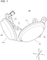
- FIG. 1 is a front perspective view illustrating configurations of a vehicular lamp according to an embodiment of the present disclosure.
- a vehicular lamp 100 is a front lamp such as a clearance lamp to be mounted on a vehicle such as a motorcycle.
- a direction of an arrow F illustrated in FIG. 1 is “front”
- a direction of an arrow B is “rear”.
- a direction of an arrow R illustrated in FIG. 1 is “right”
- a direction of an arrow L is “left”.
- a direction of an arrow U illustrated in FIG. 1 is “upper”
- a direction of an arrow D is “lower”.
- the vehicular lamp 100 includes a plurality of lamp units 51.
- the vehicular lamp 100 includes a left lamp unit 51L and a right lamp unit 51R, which are two lamp units 51 arranged in a left-right direction, will be described.
- the left lamp unit 51L is provided on a left side in the left-right direction
- the right lamp unit 51R is provided on a right side in the left-right direction.
- the left lamp unit 51L and the right lamp unit 51R may be coupled.
- the left lamp unit 51L and the right lamp unit 51R have different orientations of light emitting surfaces when attached to a vehicle. Specifically, the light emitting surface of the left lamp unit 51L faces leftward rather than forward. On the other hand, the light emitting surface of the right lamp unit 51R faces rightward rather than forward.
- the left lamp unit 51L includes a light emitting element to be described later, an outer lens (lens) 10L disposed on a front side relative to the light emitting element, and a body 11L supporting the light emitting element.
- the right lamp unit 51R includes a light emitting element to be described later, an outer lens (lens) 10R disposed on a front side relative to the light emitting element, and a body 11R supporting the light emitting element.
- FIG. 2 is an exploded perspective view illustrating detailed configurations of a right lamp unit illustrated in FIG. 1 .
- the right lamp unit 51R further includes, in addition to the outer lens 10R and the body 11R, an inner lens 12R, light emitting elements 13R, a substrate 14R supporting the light emitting elements 13, and a cord 15R for supplying power to the light emitting elements 13R.
- FIG. 2 further illustrates a cord 15L of the right lamp unit 51R and a wiring component 16 for wiring the cords 15R and 15L.
- the left lamp unit 51L has the same configurations as the right lamp unit 51R except for a configuration of the body 11L.
- the left lamp unit 51L includes, in addition to the outer lens 10L and the body 11L, an inner lens 12L, light emitting elements 13L, and a substrate 14L, which are not illustrated, and the above-described cord 15L.
- each of the inner lenses 12R and 12L is also referred to as an "inner lens 12".
- Each of the light emitting elements 13R and 13L is also referred to as a “light emitting element 13".
- Each of the substrates 14R and 14L is also referred to as a “substrate 14".
- Each of the cords 15R and 15L is also referred to as a "cord 15”.
- Each of the outer lenses 10R and 10L is also referred to as an "outer lens 10".
- Each of the bodies 11R and 11L is also referred to as a "body 11".
- the inner lens 12 is provided between the outer lens 10 and the light emitting element 13, and refracts light from the light emitting element 13.
- the light emitting element 13 is, for example, a white light emitting diode, and has a rectangular light emitting surface.
- the light emitting surface of the light emitting element 13 is provided on a front side, and a rear surface of the light emitting element 13 is supported by the substrate 14.
- the substrate 14 is supported by the body 11.
- the plurality of lamp units 51 are not limited to the configuration in which the orientations of the light emitting surfaces are different from each other when attached to the vehicle, and the orientations of the light emitting surfaces of the lamp units 51 may be the same as each other.
- the vehicular lamp 100 is not limited to a clearance lamp, and may be another type of lamp.
- the plurality of lamp units 51 are not limited to the configuration in which the lamp units 51 are arranged in the left-right direction when attached to the vehicle, and may be arranged in an upper-lower direction, for example.
- the cords 15L and 15R are not limited to the configuration of being wired by the common wiring component 16, and may be wired by wiring components different from each other.
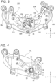
- FIG. 3 is a back perspective view illustrating a state in which two lamp units illustrated in FIG. 1 are coupled.
- FIG. 4 illustrates a configuration of a body provided in the left lamp unit illustrated in FIG. 3 .
- the body 11L of the left lamp unit 51L includes a support portion 21 that supports the substrate 14 and a coupling portion 22 that couples the body 11L and the body 11R.
- the coupling portion 22 is a plate-shaped member protruding rearward from a right end portion of the support portion 21, and is in contact with a rear surface of the body 11R of the right lamp unit 51R when the left lamp unit 51L and the right lamp unit 51R are coupled.
- the coupling portion 22 has a plurality of holes 31 into which a plurality of fixing members 35 illustrated in FIG. 3 are respectively inserted and a hole 32 into which the cord 15R illustrated in FIG. 3 is inserted.
- the coupling portion 22 further has a plurality of holes 33 into which a plurality of positioning pins to be described later are respectively inserted.
- the support portion 21 has a hole 34 into which the cord 15L illustrated in FIG. 3 is inserted.
- the coupling portion 22 is not limited to the configuration provided in the left lamp unit 51L, and may be provided in the right lamp unit 51R, or in both the left lamp unit 51L and the right lamp unit 51R.
- the left lamp unit 51L and the right lamp unit 51R may have the same configuration or different configurations.
- FIG. 5 illustrates a configuration of a body provided in the right lamp unit illustrated in FIG. 3 .
- the body 11R has a plurality of holes 41 provided in positions corresponding to the plurality of holes 31 illustrated in FIG. 4 and a hole 42 provided in a position corresponding to the hole 32 illustrated in FIG. 4 .
- the body 11R is provided with a plurality of positioning pins 43 in positions corresponding to the plurality of holes 33 illustrated in FIG. 4 when the left lamp unit 51L and the right lamp unit 51R are coupled.
- the coupling portion 22 may be in contact with a front surface of the body 11R of the right lamp unit 51R. However, when the coupling portion 22 is in contact with the rear surface of the body 11R, the coupling portion 22 can be prevented from being seen through the outer lens 10 in a front view of the vehicular lamp 100. In this case, the two lamp units 51 can be coupled by effectively utilizing a space on a rear side different from an emission side of light from the light emitting element 13. For this reason, the coupling portion 22 is preferably in contact with the rear surface of the body 11R.
- the coupling portion 22 of the lamp unit 51 is not limited to a plate-shaped member that is in contact with a surface of the body 11 of another lamp unit 51, and may be, for example, a linear member.
- the vehicular lamp 100 may include three or more lamp units 51.
- the body 11 of at least one or two of the three or more lamp units 51 includes the coupling portion 22 configured to couple the body of the at least one or two of the three or more lamp units 51 with the body 11 of another lamp unit 51.
- the substrate 14R, to which the light emitting element 13R is attached, and the inner lens 12R are attached to the body 11R.
- the outer lens 10R is attached to the body 11R.
- the body 11R and the outer lens 10R are bonded by hot plate welding using, for example, a fixture. The same work is also performed when the left lamp unit 51L is assembled. Accordingly, assembly of the left lamp unit 51L and the right lamp unit 51R is completed.
- the plurality of positioning pins 43 of the right lamp unit 51R are respectively inserted into the plurality of holes 33 of the left lamp unit 51L, so that the coupling portion 22 of the left lamp unit 51L is in contact with the body 11R of the right lamp unit 51R.
- the fixing member 35 is inserted into the hole 31 of the left lamp unit 51L and the hole 41 of the right lamp unit 51R corresponding to the hole 31. Accordingly, the left lamp unit 51L and the right lamp unit 51R can be coupled.
- the fixing member 35 is, for example, a screw having a screw head of a special shape such as a star shape. Fastening such screws in a plurality of positions can improve durability against vibration or the like of the vehicle.
- the wiring component 16 is attached to the right lamp unit 51R.
- both of the cords 15L and 15R are preferably inserted into the wiring component 16 with end portions thereof exposed to outside of the wiring component 16.
- the end portion of the cord 15L is inserted into the hole 34 of the left lamp unit 51L and connected to the substrate 14L.
- the end portion of the cord 15R is inserted into the hole 32 of the coupling portion 22 of the left lamp unit 51L and the hole 42 of the right lamp unit 51R and connected to the substrate 14R.
- the vehicular lamp 100 assembled in this manner is attached to a member such as a panel (not illustrated) provided in a front portion of the vehicle.
- the vehicular lamp 100 includes a plurality of lamp units 51 each including the light emitting element 13, the outer lens 10 disposed on the front side relative to the light emitting element 13, and the body 11 supporting the light emitting element 13.
- the body 11 of at least one of the plurality of lamp units 51 includes the coupling portion 22 that couples the body 11 of the at least one of the plurality of lamp units 51 with the body 11 of another lamp unit 51.
- the body 11 of the lamp unit 51 includes the coupling portion 22 configured to couple the body 11 of the lamp unit 51 with the body 11 of another lamp unit 51, the plurality of lamp units 51 can be integrally attached to a member such as a panel. Accordingly, work when attaching the vehicular lamp 100 to the vehicle can be further facilitated.
- the outer lens 10 and the body 11 are bonded by hot plate welding using, for example, a fixture.
- the fixture for welding the outer lens 10 and the body 11 by hot plate welding has a large size and a complicated shape.
- the outer lens 10 and the body 11 can be welded for each lamp unit 51 by hot plate welding, and it is possible to implement a reduced size and a simplified shape of the fixture used for hot plate welding.
- the coupling portion 22 is a plate-shaped member that is in contact with a surface of another body 11 when the body 11 including the coupling portion 22 and the other body 11 are coupled. In this manner, since the coupling portion 22 of the body 11 and the other body 11 are coupled in a surface contact state, a plurality of bodies 11 can be coupled firmly.
- the vehicular lamp 100 further includes the cord 15 that supplies power to the light emitting element 13 for each lamp unit 51.
- the cord 15 of each lamp unit 51 is wired by the common wiring component 16. With such a configuration, the number of components of the wiring component 16 can be reduced, and a reduced space can be achieved.
- the orientations of the light emitting surfaces of the light emitting elements 13 of the respective lamp units 51 differ from one another in a state in which the lamp units 51 are attached to the vehicle.
- the fixture for welding the outer lens 10 and the body 11 by hot plate welding has a large size and a complicated shape.
- the shape of the fixture is further complicated.
- the outer lens 10 and the body 11 can be welded by hot plate welding for each lamp unit 51, which is particularly effective when the light emitting surfaces of the light emitting elements 13 of the respective lamp units 51 differ from one another.
Landscapes
- Engineering & Computer Science (AREA)
- General Engineering & Computer Science (AREA)
- Mechanical Engineering (AREA)
- Non-Portable Lighting Devices Or Systems Thereof (AREA)
Abstract
Description
- The present disclosure relates to a vehicular lamp to be mounted on a vehicle.
- Techniques relating to a vehicular lamp are being developed in the related art. For example, a vehicular lamp disclosed in Patent Literature 1 is a front lamp for a two-wheeled vehicle, which includes first and second lamp units arranged side by side in a left-right direction, and a panel member surrounding the first and second lamp units. Lenses of the first and second lamp units are formed in a convex shape along a surface contour of the panel member.
- Patent Literature 1:
JP2015-076364A - In the technique described in Patent Literature 1, when the front lamp for a two-wheeled vehicle is attached to the vehicle, the first and second lamp units are separately attached to the panel member, and the panel member to which the first and second lamp units are attached is attached to the vehicle.
- An object of the present disclosure is to provide a vehicular lamp that can further facilitate work when attaching a vehicular lamp to a vehicle.
- A vehicular lamp according to an aspect of the present disclosure is a vehicular lamp configured to be mounted on a vehicle, the vehicular lamp including a plurality of lamp units, each of the plurality of lamp units including a light emitting element, a lens disposed on a front side relative to the light emitting element, and a body supporting the light emitting element. The body of at least one of the plurality of lamp units includes a coupling portion configured to couple the body of the at least one of the plurality of lamp units with the body of another one of the plurality of lamp units.
- According to the present disclosure, it is possible to further facilitate work when attaching a vehicular lamp to a vehicle.
-
- [
FIG. 1] FIG. 1 is a front perspective view illustrating configurations of a vehicular lamp according to an embodiment of the present disclosure. - [
FIG. 2] FIG. 2 is an exploded perspective view illustrating detailed configurations of a right lamp unit illustrated inFIG. 1 . - [
FIG. 3] FIG. 3 is a back perspective view illustrating a state in which two lamp units illustrated inFIG. 1 are coupled. - [
FIG. 4] FIG. 4 illustrates a configuration of a body provided in the left lamp unit illustrated inFIG. 3 . - [
FIG. 5] FIG. 5 illustrates a configuration of a body provided in the right lamp unit illustrated inFIG. 3 . - The present disclosure will be described with reference to the drawings.
FIG. 1 is a front perspective view illustrating configurations of a vehicular lamp according to an embodiment of the present disclosure. - Referring to
FIG. 1 , avehicular lamp 100 is a front lamp such as a clearance lamp to be mounted on a vehicle such as a motorcycle. In this example, a direction of an arrow F illustrated inFIG. 1 is "front", and a direction of an arrow B is "rear". A direction of an arrow R illustrated inFIG. 1 is "right", and a direction of an arrow L is "left". A direction of an arrow U illustrated inFIG. 1 is "upper", and a direction of an arrow D is "lower". - The
vehicular lamp 100 includes a plurality of lamp units 51. In this example, a case in which thevehicular lamp 100 includes aleft lamp unit 51L and aright lamp unit 51R, which are two lamp units 51 arranged in a left-right direction, will be described. For example, theleft lamp unit 51L is provided on a left side in the left-right direction, and theright lamp unit 51R is provided on a right side in the left-right direction. - The
left lamp unit 51L and theright lamp unit 51R may be coupled. Theleft lamp unit 51L and theright lamp unit 51R have different orientations of light emitting surfaces when attached to a vehicle. Specifically, the light emitting surface of theleft lamp unit 51L faces leftward rather than forward. On the other hand, the light emitting surface of theright lamp unit 51R faces rightward rather than forward. - The
left lamp unit 51L includes a light emitting element to be described later, an outer lens (lens) 10L disposed on a front side relative to the light emitting element, and abody 11L supporting the light emitting element. Theright lamp unit 51R includes a light emitting element to be described later, an outer lens (lens) 10R disposed on a front side relative to the light emitting element, and abody 11R supporting the light emitting element. -
FIG. 2 is an exploded perspective view illustrating detailed configurations of a right lamp unit illustrated inFIG. 1 . Referring toFIG. 2 , theright lamp unit 51R further includes, in addition to theouter lens 10R and thebody 11R, aninner lens 12R,light emitting elements 13R, asubstrate 14R supporting the light emitting elements 13, and acord 15R for supplying power to thelight emitting elements 13R. - In addition to the
outer lens 10R, theinner lens 12R, thelight emitting elements 13R, thesubstrate 14R, and thecord 15R of theright lamp unit 51R,FIG. 2 further illustrates acord 15L of theright lamp unit 51R and awiring component 16 for wiring thecords - The
left lamp unit 51L has the same configurations as theright lamp unit 51R except for a configuration of thebody 11L. Theleft lamp unit 51L includes, in addition to theouter lens 10L and thebody 11L, an inner lens 12L, light emitting elements 13L, and a substrate 14L, which are not illustrated, and the above-describedcord 15L. - Hereinafter, each of the
inner lenses 12R and 12L is also referred to as an "inner lens 12". Each of thelight emitting elements 13R and 13L is also referred to as a "light emitting element 13". Each of thesubstrates 14R and 14L is also referred to as a "substrate 14". Each of thecords outer lenses bodies - The inner lens 12 is provided between the outer lens 10 and the light emitting element 13, and refracts light from the light emitting element 13.
- The light emitting element 13 is, for example, a white light emitting diode, and has a rectangular light emitting surface. The light emitting surface of the light emitting element 13 is provided on a front side, and a rear surface of the light emitting element 13 is supported by the substrate 14. The substrate 14 is supported by the body 11.
- The plurality of lamp units 51 are not limited to the configuration in which the orientations of the light emitting surfaces are different from each other when attached to the vehicle, and the orientations of the light emitting surfaces of the lamp units 51 may be the same as each other. The
vehicular lamp 100 is not limited to a clearance lamp, and may be another type of lamp. - As illustrated in
FIG. 1 , the plurality of lamp units 51 are not limited to the configuration in which the lamp units 51 are arranged in the left-right direction when attached to the vehicle, and may be arranged in an upper-lower direction, for example. - The
cords common wiring component 16, and may be wired by wiring components different from each other. -
FIG. 3 is a back perspective view illustrating a state in which two lamp units illustrated inFIG. 1 are coupled.FIG. 4 illustrates a configuration of a body provided in the left lamp unit illustrated inFIG. 3 . - Referring to
FIGS. 3 and 4 , thebody 11L of theleft lamp unit 51L includes asupport portion 21 that supports the substrate 14 and acoupling portion 22 that couples thebody 11L and thebody 11R. Thecoupling portion 22 is a plate-shaped member protruding rearward from a right end portion of thesupport portion 21, and is in contact with a rear surface of thebody 11R of theright lamp unit 51R when theleft lamp unit 51L and theright lamp unit 51R are coupled. - As illustrated in
FIG. 4 , thecoupling portion 22 has a plurality ofholes 31 into which a plurality offixing members 35 illustrated inFIG. 3 are respectively inserted and ahole 32 into which thecord 15R illustrated inFIG. 3 is inserted. Thecoupling portion 22 further has a plurality ofholes 33 into which a plurality of positioning pins to be described later are respectively inserted. Thesupport portion 21 has ahole 34 into which thecord 15L illustrated inFIG. 3 is inserted. - The
coupling portion 22 is not limited to the configuration provided in theleft lamp unit 51L, and may be provided in theright lamp unit 51R, or in both theleft lamp unit 51L and theright lamp unit 51R. When thecoupling portion 22 is provided in both theleft lamp unit 51L and theright lamp unit 51R, theleft lamp unit 51L and theright lamp unit 51R may have the same configuration or different configurations. -
FIG. 5 illustrates a configuration of a body provided in the right lamp unit illustrated inFIG. 3 . Referring toFIGS. 3 to 5 , when theleft lamp unit 51L and theright lamp unit 51R are coupled, thebody 11R has a plurality ofholes 41 provided in positions corresponding to the plurality ofholes 31 illustrated inFIG. 4 and ahole 42 provided in a position corresponding to thehole 32 illustrated inFIG. 4 . - The
body 11R is provided with a plurality of positioning pins 43 in positions corresponding to the plurality ofholes 33 illustrated inFIG. 4 when theleft lamp unit 51L and theright lamp unit 51R are coupled. - The
coupling portion 22 may be in contact with a front surface of thebody 11R of theright lamp unit 51R. However, when thecoupling portion 22 is in contact with the rear surface of thebody 11R, thecoupling portion 22 can be prevented from being seen through the outer lens 10 in a front view of thevehicular lamp 100. In this case, the two lamp units 51 can be coupled by effectively utilizing a space on a rear side different from an emission side of light from the light emitting element 13. For this reason, thecoupling portion 22 is preferably in contact with the rear surface of thebody 11R. - The
coupling portion 22 of the lamp unit 51 is not limited to a plate-shaped member that is in contact with a surface of the body 11 of another lamp unit 51, and may be, for example, a linear member. - The
vehicular lamp 100 may include three or more lamp units 51. In this case, the body 11 of at least one or two of the three or more lamp units 51 includes thecoupling portion 22 configured to couple the body of the at least one or two of the three or more lamp units 51 with the body 11 of another lamp unit 51. - Referring again to
FIG. 2 , when theright lamp unit 51R is assembled, thesubstrate 14R, to which thelight emitting element 13R is attached, and theinner lens 12R are attached to thebody 11R. Thereafter, theouter lens 10R is attached to thebody 11R. Thebody 11R and theouter lens 10R are bonded by hot plate welding using, for example, a fixture. The same work is also performed when theleft lamp unit 51L is assembled. Accordingly, assembly of theleft lamp unit 51L and theright lamp unit 51R is completed. - Thereafter, as illustrated in
FIGS. 3 to 5 , the plurality of positioning pins 43 of theright lamp unit 51R are respectively inserted into the plurality ofholes 33 of theleft lamp unit 51L, so that thecoupling portion 22 of theleft lamp unit 51L is in contact with thebody 11R of theright lamp unit 51R. Thereafter, the fixingmember 35 is inserted into thehole 31 of theleft lamp unit 51L and thehole 41 of theright lamp unit 51R corresponding to thehole 31. Accordingly, theleft lamp unit 51L and theright lamp unit 51R can be coupled. - The fixing
member 35 is, for example, a screw having a screw head of a special shape such as a star shape. Fastening such screws in a plurality of positions can improve durability against vibration or the like of the vehicle. - After the
left lamp unit 51L and theright lamp unit 51R are coupled, for example, thewiring component 16 is attached to theright lamp unit 51R. At this time, both of thecords wiring component 16 with end portions thereof exposed to outside of thewiring component 16. - Thereafter, for example, the end portion of the
cord 15L is inserted into thehole 34 of theleft lamp unit 51L and connected to the substrate 14L. The end portion of thecord 15R is inserted into thehole 32 of thecoupling portion 22 of theleft lamp unit 51L and thehole 42 of theright lamp unit 51R and connected to thesubstrate 14R. Thevehicular lamp 100 assembled in this manner is attached to a member such as a panel (not illustrated) provided in a front portion of the vehicle. - As described above, the
vehicular lamp 100 according to the embodiment of the present disclosure includes a plurality of lamp units 51 each including the light emitting element 13, the outer lens 10 disposed on the front side relative to the light emitting element 13, and the body 11 supporting the light emitting element 13. The body 11 of at least one of the plurality of lamp units 51 includes thecoupling portion 22 that couples the body 11 of the at least one of the plurality of lamp units 51 with the body 11 of another lamp unit 51. - In this manner, since the body 11 of the lamp unit 51 includes the
coupling portion 22 configured to couple the body 11 of the lamp unit 51 with the body 11 of another lamp unit 51, the plurality of lamp units 51 can be integrally attached to a member such as a panel. Accordingly, work when attaching thevehicular lamp 100 to the vehicle can be further facilitated. - The outer lens 10 and the body 11 are bonded by hot plate welding using, for example, a fixture. When the plurality of lamp units 51 are integrally formed from a beginning, the fixture for welding the outer lens 10 and the body 11 by hot plate welding has a large size and a complicated shape. In contrast, as described above, since the plurality of lamp units 51 are separate from each other and coupled via the
coupling portion 22, the outer lens 10 and the body 11 can be welded for each lamp unit 51 by hot plate welding, and it is possible to implement a reduced size and a simplified shape of the fixture used for hot plate welding. - In the
vehicular lamp 100 according to the embodiment of the present disclosure, thecoupling portion 22 is a plate-shaped member that is in contact with a surface of another body 11 when the body 11 including thecoupling portion 22 and the other body 11 are coupled. In this manner, since thecoupling portion 22 of the body 11 and the other body 11 are coupled in a surface contact state, a plurality of bodies 11 can be coupled firmly. - The
vehicular lamp 100 according to the embodiment of the present disclosure further includes the cord 15 that supplies power to the light emitting element 13 for each lamp unit 51. The cord 15 of each lamp unit 51 is wired by thecommon wiring component 16. With such a configuration, the number of components of thewiring component 16 can be reduced, and a reduced space can be achieved. - In the
vehicular lamp 100 according to the embodiment of the present disclosure, the orientations of the light emitting surfaces of the light emitting elements 13 of the respective lamp units 51 differ from one another in a state in which the lamp units 51 are attached to the vehicle. - Here, as described above, when the plurality of lamp units 51 are integrally formed from a beginning, the fixture for welding the outer lens 10 and the body 11 by hot plate welding has a large size and a complicated shape. When the orientations of the light emitting surfaces of the light emitting elements 13 of the respective lamp units 51 differ from one another in a state in which the lamp units 51 are attached to the vehicle, the shape of the fixture is further complicated.
- In contrast, since the plurality of lamp units 51 are separated from each other as described above, the outer lens 10 and the body 11 can be welded by hot plate welding for each lamp unit 51, which is particularly effective when the light emitting surfaces of the light emitting elements 13 of the respective lamp units 51 differ from one another.
- Although the embodiment of the present disclosure is described above, it is needless to say that the technical scope of the present disclosure should not be construed as being limited by the description of the embodiment. It should be understood by a person skilled in the art that the present embodiment is merely an example, and that various modifications of the embodiment are possible within the scope of the inventions described in the claims. The technical scope of the present disclosure is determined based on the scope of the inventions described in the claims and an equivalent scope thereof.
- The present application is based on a
Japanese patent application No. 2022-059252 filed on March 31, 2022
Claims (4)
- A vehicular lamp configured to be mounted on a vehicle, the vehicular lamp comprising:a plurality of lamp units, each of the plurality of lamp units comprising a light emitting element, a lens disposed on a front side relative to the light emitting element, and a body supporting the light emitting element,wherein the body of at least one of the plurality of lamp units comprises a coupling portion configured to couple the body of the at least one of the plurality of lamp units with the body of another one of the plurality of lamp units.
- The vehicular lamp according to claim 1, wherein the coupling portion is a plate-shaped member configured to contact a surface of another body in a state in which the body comprising the coupling portion is coupled with the another body.
- The vehicular lamp according to claim 1 or 2, further comprising:a cord configured to supply power to the light emitting element for each of the lamp units,wherein the cord of each of the lamp units is wired by a common wiring component.
- The vehicular lamp according to any one of claims 1 to 3, wherein orientations of light emitting surfaces of light emitting elements of the respective lamp units differ from one another in a state in which the lamp units are attached to the vehicle.
Applications Claiming Priority (2)
| Application Number | Priority Date | Filing Date | Title |
|---|---|---|---|
| JP2022059252 | 2022-03-31 | ||
| PCT/JP2023/011179 WO2023189927A1 (en) | 2022-03-31 | 2023-03-22 | Vehicular lamp |
Publications (2)
| Publication Number | Publication Date |
|---|---|
| EP4502460A1 true EP4502460A1 (en) | 2025-02-05 |
| EP4502460A4 EP4502460A4 (en) | 2025-03-26 |
Family
ID=88201944
Family Applications (1)
| Application Number | Title | Priority Date | Filing Date |
|---|---|---|---|
| EP23779939.0A Withdrawn EP4502460A4 (en) | 2022-03-31 | 2023-03-22 | VEHICLE LAMP |
Country Status (5)
| Country | Link |
|---|---|
| US (1) | US20250216048A1 (en) |
| EP (1) | EP4502460A4 (en) |
| JP (1) | JPWO2023189927A1 (en) |
| CN (1) | CN118984919A (en) |
| WO (1) | WO2023189927A1 (en) |
Family Cites Families (15)
| Publication number | Priority date | Publication date | Assignee | Title |
|---|---|---|---|---|
| US6123441A (en) * | 1992-08-28 | 2000-09-26 | Kasboske; George C. | Modular lighting unit |
| US5663707A (en) * | 1995-04-11 | 1997-09-02 | Bartilucci; Gary M. | Signalling light visible through a rear view window of a vehicle |
| JP4115921B2 (en) * | 2003-11-04 | 2008-07-09 | 株式会社小糸製作所 | Vehicle headlamp |
| JP4796364B2 (en) * | 2005-09-15 | 2011-10-19 | 川崎重工業株式会社 | VEHICLE LAMP DEVICE AND MOTORCYCLE HAVING THE SAME |
| AU2008200865B2 (en) * | 2007-03-30 | 2010-03-18 | Honda Motor Co., Ltd. | Motocycle front lighting apparatus structure |
| US7789544B1 (en) * | 2007-10-10 | 2010-09-07 | Baja Designs, Inc. | Modular off-road accessory light rack |
| JP5955110B2 (en) * | 2012-06-05 | 2016-07-20 | 株式会社小糸製作所 | Vehicle lighting |
| JP6261276B2 (en) | 2013-10-11 | 2018-01-17 | 株式会社小糸製作所 | Vehicle lighting |
| CN103759203A (en) * | 2013-12-31 | 2014-04-30 | 东莞市贻嘉光电科技有限公司 | LED automobile lamp combined structure |
| JP6262539B2 (en) * | 2014-01-15 | 2018-01-17 | 株式会社小糸製作所 | Vehicle lighting |
| US9676322B2 (en) * | 2015-05-05 | 2017-06-13 | Kc Hilites Inc. | Light linking system |
| JP2019012623A (en) * | 2017-06-30 | 2019-01-24 | 株式会社小糸製作所 | Vehicular lighting fixture |
| WO2019232210A1 (en) * | 2018-05-30 | 2019-12-05 | Federal Signal Corporation | Modular flexible light bar |
| CN210592252U (en) * | 2019-09-10 | 2020-05-22 | 重庆亮迅科技有限公司 | A combined motorcycle headlight |
| JP2022059252A (en) | 2020-10-01 | 2022-04-13 | 株式会社オリジン | Electromagnetic wave shield |
-
2023
- 2023-03-22 EP EP23779939.0A patent/EP4502460A4/en not_active Withdrawn
- 2023-03-22 US US18/852,879 patent/US20250216048A1/en active Pending
- 2023-03-22 JP JP2024511950A patent/JPWO2023189927A1/ja active Pending
- 2023-03-22 WO PCT/JP2023/011179 patent/WO2023189927A1/en not_active Ceased
- 2023-03-22 CN CN202380032206.XA patent/CN118984919A/en active Pending
Also Published As
| Publication number | Publication date |
|---|---|
| WO2023189927A1 (en) | 2023-10-05 |
| US20250216048A1 (en) | 2025-07-03 |
| CN118984919A (en) | 2024-11-19 |
| JPWO2023189927A1 (en) | 2023-10-05 |
| EP4502460A4 (en) | 2025-03-26 |
Similar Documents
| Publication | Publication Date | Title |
|---|---|---|
| US10442345B2 (en) | Vehicular lamp and light source unit | |
| JP5472598B2 (en) | LED light source unit for vehicle lamp | |
| US9206954B2 (en) | Light source unit and vehicular lamp | |
| WO2014091826A1 (en) | Headlight device for motorcycle | |
| US7686487B2 (en) | Door mirror equipped with lamp body | |
| US7789544B1 (en) | Modular off-road accessory light rack | |
| CN217503538U (en) | Lamp for vehicle and vehicle comprising same | |
| WO2019176869A1 (en) | Light source unit and method for producing mounting member which is used for same | |
| US20250216048A1 (en) | Vehicular lamp | |
| JP3089006B1 (en) | Motorcycle lamp unit | |
| CN113154333B (en) | Lamp for vehicle | |
| JP6889592B2 (en) | Lamp | |
| EP4466492B1 (en) | Lighting device for a motor vehicle | |
| US20240166126A1 (en) | Steering wheel | |
| US20230024988A1 (en) | Light-emitting unit for door mirror | |
| JP7261559B2 (en) | Headlamp device for saddle-riding vehicle | |
| JP2000090712A (en) | Vehicle sign lights | |
| US12560295B2 (en) | Vehicle lamp | |
| JP2002178972A (en) | Motorcycle headlamp mounting structure | |
| JP7491754B2 (en) | Vehicle Lighting | |
| JP6994893B2 (en) | Lamp | |
| JP4229737B2 (en) | Door mirror with side blinker | |
| CN116829870A (en) | Vehicle mounted light source unit | |
| JP4798177B2 (en) | Vehicle lighting | |
| JP2021022423A (en) | Manufacturing method of light-emitting device and light-emitting device |
Legal Events
| Date | Code | Title | Description |
|---|---|---|---|
| STAA | Information on the status of an ep patent application or granted ep patent |
Free format text: STATUS: THE INTERNATIONAL PUBLICATION HAS BEEN MADE |
|
| PUAI | Public reference made under article 153(3) epc to a published international application that has entered the european phase |
Free format text: ORIGINAL CODE: 0009012 |
|
| STAA | Information on the status of an ep patent application or granted ep patent |
Free format text: STATUS: REQUEST FOR EXAMINATION WAS MADE |
|
| 17P | Request for examination filed |
Effective date: 20240930 |
|
| AK | Designated contracting states |
Kind code of ref document: A1 Designated state(s): AL AT BE BG CH CY CZ DE DK EE ES FI FR GB GR HR HU IE IS IT LI LT LU LV MC ME MK MT NL NO PL PT RO RS SE SI SK SM TR |
|
| A4 | Supplementary search report drawn up and despatched |
Effective date: 20250225 |
|
| RIC1 | Information provided on ipc code assigned before grant |
Ipc: B62J 6/026 20200101ALI20250219BHEP Ipc: B60Q 1/00 20060101ALI20250219BHEP Ipc: F21Y 115/10 20160101ALI20250219BHEP Ipc: F21W 103/10 20180101ALI20250219BHEP Ipc: F21V 23/00 20150101ALI20250219BHEP Ipc: F21S 45/00 20180101AFI20250219BHEP |
|
| DAV | Request for validation of the european patent (deleted) | ||
| DAX | Request for extension of the european patent (deleted) | ||
| STAA | Information on the status of an ep patent application or granted ep patent |
Free format text: STATUS: THE APPLICATION IS DEEMED TO BE WITHDRAWN |
|
| 18D | Application deemed to be withdrawn |
Effective date: 20250916 |