EP4502439A1 - Electrical component assembly, electrical component assembly manufacturing method, and vehicle brake hydraulic pressure control device - Google Patents
Electrical component assembly, electrical component assembly manufacturing method, and vehicle brake hydraulic pressure control device Download PDFInfo
- Publication number
- EP4502439A1 EP4502439A1 EP23780719.3A EP23780719A EP4502439A1 EP 4502439 A1 EP4502439 A1 EP 4502439A1 EP 23780719 A EP23780719 A EP 23780719A EP 4502439 A1 EP4502439 A1 EP 4502439A1
- Authority
- EP
- European Patent Office
- Prior art keywords
- control board
- electrical component
- assembly
- housing
- setting
- Prior art date
- Legal status (The legal status is an assumption and is not a legal conclusion. Google has not performed a legal analysis and makes no representation as to the accuracy of the status listed.)
- Pending
Links
Images






Classifications
-
- H—ELECTRICITY
- H01—ELECTRIC ELEMENTS
- H01F—MAGNETS; INDUCTANCES; TRANSFORMERS; SELECTION OF MATERIALS FOR THEIR MAGNETIC PROPERTIES
- H01F7/00—Magnets
- H01F7/06—Electromagnets; Actuators including electromagnets
- H01F7/064—Circuit arrangements for actuating electromagnets
-
- B—PERFORMING OPERATIONS; TRANSPORTING
- B60—VEHICLES IN GENERAL
- B60T—VEHICLE BRAKE CONTROL SYSTEMS OR PARTS THEREOF; BRAKE CONTROL SYSTEMS OR PARTS THEREOF, IN GENERAL; ARRANGEMENT OF BRAKING ELEMENTS ON VEHICLES IN GENERAL; PORTABLE DEVICES FOR PREVENTING UNWANTED MOVEMENT OF VEHICLES; VEHICLE MODIFICATIONS TO FACILITATE COOLING OF BRAKES
- B60T8/00—Arrangements for adjusting wheel-braking force to meet varying vehicular or ground-surface conditions, e.g. limiting or varying distribution of braking force
- B60T8/32—Arrangements for adjusting wheel-braking force to meet varying vehicular or ground-surface conditions, e.g. limiting or varying distribution of braking force responsive to a speed condition, e.g. acceleration or deceleration
- B60T8/34—Arrangements for adjusting wheel-braking force to meet varying vehicular or ground-surface conditions, e.g. limiting or varying distribution of braking force responsive to a speed condition, e.g. acceleration or deceleration having a fluid pressure regulator responsive to a speed condition
- B60T8/343—Systems characterised by their lay-out
-
- B—PERFORMING OPERATIONS; TRANSPORTING
- B60—VEHICLES IN GENERAL
- B60T—VEHICLE BRAKE CONTROL SYSTEMS OR PARTS THEREOF; BRAKE CONTROL SYSTEMS OR PARTS THEREOF, IN GENERAL; ARRANGEMENT OF BRAKING ELEMENTS ON VEHICLES IN GENERAL; PORTABLE DEVICES FOR PREVENTING UNWANTED MOVEMENT OF VEHICLES; VEHICLE MODIFICATIONS TO FACILITATE COOLING OF BRAKES
- B60T8/00—Arrangements for adjusting wheel-braking force to meet varying vehicular or ground-surface conditions, e.g. limiting or varying distribution of braking force
- B60T8/32—Arrangements for adjusting wheel-braking force to meet varying vehicular or ground-surface conditions, e.g. limiting or varying distribution of braking force responsive to a speed condition, e.g. acceleration or deceleration
- B60T8/34—Arrangements for adjusting wheel-braking force to meet varying vehicular or ground-surface conditions, e.g. limiting or varying distribution of braking force responsive to a speed condition, e.g. acceleration or deceleration having a fluid pressure regulator responsive to a speed condition
- B60T8/343—Systems characterised by their lay-out
- B60T8/344—Hydraulic systems
-
- B—PERFORMING OPERATIONS; TRANSPORTING
- B60—VEHICLES IN GENERAL
- B60T—VEHICLE BRAKE CONTROL SYSTEMS OR PARTS THEREOF; BRAKE CONTROL SYSTEMS OR PARTS THEREOF, IN GENERAL; ARRANGEMENT OF BRAKING ELEMENTS ON VEHICLES IN GENERAL; PORTABLE DEVICES FOR PREVENTING UNWANTED MOVEMENT OF VEHICLES; VEHICLE MODIFICATIONS TO FACILITATE COOLING OF BRAKES
- B60T8/00—Arrangements for adjusting wheel-braking force to meet varying vehicular or ground-surface conditions, e.g. limiting or varying distribution of braking force
- B60T8/32—Arrangements for adjusting wheel-braking force to meet varying vehicular or ground-surface conditions, e.g. limiting or varying distribution of braking force responsive to a speed condition, e.g. acceleration or deceleration
- B60T8/34—Arrangements for adjusting wheel-braking force to meet varying vehicular or ground-surface conditions, e.g. limiting or varying distribution of braking force responsive to a speed condition, e.g. acceleration or deceleration having a fluid pressure regulator responsive to a speed condition
- B60T8/36—Arrangements for adjusting wheel-braking force to meet varying vehicular or ground-surface conditions, e.g. limiting or varying distribution of braking force responsive to a speed condition, e.g. acceleration or deceleration having a fluid pressure regulator responsive to a speed condition including a pilot valve responding to an electromagnetic force
- B60T8/3615—Electromagnetic valves specially adapted for anti-lock brake and traction control systems
- B60T8/3675—Electromagnetic valves specially adapted for anti-lock brake and traction control systems integrated in modulator units
- B60T8/368—Electromagnetic valves specially adapted for anti-lock brake and traction control systems integrated in modulator units combined with other mechanical components, e.g. pump units, master cylinders
-
- H—ELECTRICITY
- H01—ELECTRIC ELEMENTS
- H01F—MAGNETS; INDUCTANCES; TRANSFORMERS; SELECTION OF MATERIALS FOR THEIR MAGNETIC PROPERTIES
- H01F7/00—Magnets
- H01F7/06—Electromagnets; Actuators including electromagnets
- H01F7/08—Electromagnets; Actuators including electromagnets with armatures
- H01F7/126—Supporting or mounting
-
- F—MECHANICAL ENGINEERING; LIGHTING; HEATING; WEAPONS; BLASTING
- F16—ENGINEERING ELEMENTS AND UNITS; GENERAL MEASURES FOR PRODUCING AND MAINTAINING EFFECTIVE FUNCTIONING OF MACHINES OR INSTALLATIONS; THERMAL INSULATION IN GENERAL
- F16D—COUPLINGS FOR TRANSMITTING ROTATION; CLUTCHES; BRAKES
- F16D2250/00—Manufacturing; Assembly
- F16D2250/0084—Assembly or disassembly
Definitions
- the present invention relates to an electrical component assembly, a method of manufacturing the electrical component assembly, and a vehicle brake hydraulic pressure control device.
- the vehicle brake hydraulic pressure control device includes a base body with an internal brake fluid passage and a solenoid valve attached to one surface of the base body.
- An electrical component assembly is attached to one surface of the base body; the electrical component assembly includes a coil assembly, a bus bar terminal body, and a connector terminal body as electrical components, covered by a housing.
- the electrical components such as the coil assembly are connected to a control board disposed in the housing.
- Patent Literature 1 A known method for mounting the control board in the housing is disclosed in Patent Literature 1.
- the method involves mounting the electrical components in the housing in advance, aligning each of the through-holes of the control board with the tip end portion of each of the connecting terminals of the preassembled electrical components, and pushing the control board toward the electrical components. This enables the connecting terminals of the electrical components to be pressed into the through-holes of the control board, thereby electrically connecting the electrical components to the control board.
- Patent Literature 1 JP WO2018/151264 A1
- Patent Literature 1 involves aligning the connecting terminals of the electrical components with the through-holes of the control board via the housing.
- the structure of the housing becomes complicated, and high dimensional accuracy and high assembly accuracy are required for each electrical component and the housing involved in the alignment, leading to increased costs.
- the present invention aims to solve the aforementioned problem by providing an electrical component assembly, a method of manufacturing the electrical component assembly, and a vehicle brake hydraulic pressure control device, which can simplify the structure of the housing, enhance the ease of assembly of the electrical component, and reduce costs.
- an electrical component assembly is configured by mounting a control board assembly in a housing.
- the control board assembly comprises a control board and an electrical component mounted on the control board via connecting terminals.
- an assembling method in which an electrical component is mounted on a control board in advance to form a control board assembly, and then this control board assembly is mounted in a housing. Therefore, there is no need to use a conventional assembling method, which requires that an electrical component is mounted in a housing in advance, and then a control board is mounted in the housing while aligning connecting terminals of the electrical component with the control board (through-holes of the control board). Consequently, high dimensional accuracy and high assembly accuracy required for aligning the connecting terminals of the electrical component with the control board (through-holes of the control board) are not required, and the structure of the housing can be simplified.
- the electrical component assembly can be formed simply by mounting the control board assembly in the housing, the ease of assembly can be enhanced. As a result, the electrical component assembly according to the present invention can reduce costs.
- control board has fixing holes for fixing the electrical component
- electrical component includes a terminal main body in which the connecting terminals are integrated with resin, and fixing projections provided on the terminal main body and fitted into the fixing holes.
- the terminal main body can be fixed to the control board by fitting the fixing projections of the terminal main body into the fixing holes of the control board. Further, since the terminal main body can be directly fixed to the control board, the attachment strength is improved, and even when an unintentional external force is applied to the terminal main body, the fixing projections resist the external force. This can effectively prevent an external force load from being applied to a portion where the connecting terminals and the control board are electrically connected.
- the connecting terminals are press-fit terminals inserted into through-holes formed in the control board.
- the electrical component assembly preferably comprises: board positioning holes formed in the control board for fixing the control board to the housing; and housing-side projections formed on the housing for fixing the control board and fitted into the board positioning holes.
- control board assembly can be fixed to the housing by fitting the housing-side projections of the housing into the board positioning holes of the control board. Therefore, the control board assembly can be easily mounted in the housing, thereby enhancing the ease of assembly.
- the electrical component in the control board assembly is either one of a coil assembly for driving a solenoid valve, a bus bar terminal body connected to an electric motor, and a connector terminal body.
- a vehicle brake hydraulic pressure control device is equipped with the electrical component assembly as described above.
- the vehicle brake hydraulic pressure control device is connected between a master cylinder and a wheel brake to control brake hydraulic pressure acting on the wheel brake.
- the electrical component can be reliably connected to the control board, so that the quality of the product can be improved and the reliability of brake hydraulic pressure control by the device can be improved as well. Further, the vehicle brake hydraulic pressure control device can reduce costs.
- the present invention provides a method of manufacturing the electrical component assembly as described above, comprising the steps of: an electrical component setting step of setting the electrical component on an assembly jig; an assembling step of setting the control board on the assembly jig, and electrically connecting the connecting terminals of the electrical component set on the assembly jig in the electrical component setting step to the control board to assemble the control board assembly; and a control board assembly setting step of setting the control board assembly assembled in the assembling step in the housing.
- the method of manufacturing the electrical component assembly according to the present invention allows for positioning of the electrical component using the assembly jig, so that the positioning accuracy of the electrical component is improved. Further, since the connecting terminals of the electrical component are connected to the control board using the assembly jig, high dimensional accuracy and high assembly accuracy for aligning the electrical component with the control board are not required. This can enhance the ease of assembly and reduce costs.
- the present invention provides a method of manufacturing the electrical component assembly as described above, comprising the steps of: an electrical component setting step of setting the electrical component on an assembly jig; an assembling step of setting the control board on the assembly jig, and electrically connecting the connecting terminals of the electrical component set on the assembly jig in the electrical component setting step to the control board to assemble the control board assembly; and a control board assembly setting step of setting the control board assembly assembled in the assembling step in the housing, wherein the control board assembly setting step comprises the steps of: fitting the housing-side projections into the board positioning holes; and heat staking the housing-side projections.
- the method of manufacturing the electrical component assembly according to the present invention allows for positioning of the electrical component using the assembly jig, so that the positioning accuracy of the electrical component is improved. Further, since the connecting terminals of the electrical component are connected to the control board using the assembly jig, high dimensional accuracy and high assembly accuracy for aligning the electrical component with the control board are not required. This can enhance the ease of assembly and reduce costs.
- control board assembly can be reliably fixed to the housing by heat staking. Therefore, the control board assembly can be positioned to the housing with high precision.
- the electrical component assembly, the method of manufacturing an electrical component assembly, and the vehicle brake hydraulic pressure control device according to the present invention can simplify the structure of the housing, enhance the ease of assembly of the electrical component, and reduce costs.
- a vehicle brake hydraulic pressure control device 100 is connected between a master cylinder (not shown) and wheel brakes to control brake hydraulic pressure acting on the wheel brakes.
- the vehicle brake hydraulic pressure control device 100 includes a base body 110 and an electrical component assembly 1 attached to one surface of the base body 110.
- Solenoid valves 120 corresponding to brake systems mounted on a vehicle, various sensors such as pressure sensors (not shown), an electric motor M, and a reciprocating pump P are attached to the base body 110.
- the electrical component assembly 1 functions as an electronic control unit that detects the behavior of the vehicle body and controls the opening and closing of the solenoid valves 120 and the operation of the electric motor M.
- the base body 110 is a metal component formed in a generally rectangular prism shape, in which brake fluid paths (oil paths), not shown, are formed. Ports and the like for connecting the piping that leads to the wheel brakes are formed at an outer surface (not shown) of the base body 110.
- the vehicle brake hydraulic pressure control device 100 varies the brake fluid pressure within the brake fluid passages by operating the solenoid valves 120 and the electric motor M through the control board 11 in the electrical component assembly 1, based on the behavior of the vehicle.
- the electrical component assembly 1 includes a housing 2 made of plastic resin and a control board assembly 3 mounted in the housing 2.
- the housing 2 is a box body integrally fixed to an upper surface of the base body 110 (see FIG. 1 ) by means such as screw fastening.
- the housing 2 houses the control board assembly 3 and also houses the solenoid valves 120 protruding from the base body 110 and a motor bus bar (not shown).
- the housing 2 is open at its upper surface side and lower surface side of FIG. 3 .
- the upper surface side is the surface opposite the base body 110 (see FIG. 1 , the same applies hereinafter), where a lid member (not shown) to be described later will be attached.
- the lower surface side is the base body 110 side.
- the housing 2 includes a plate-shaped bottom wall portion 24, a lid member-side peripheral wall portion 25 provided on the upper surface side of the bottom wall portion 24, and a base body-side peripheral wall portion 21 provided on the lower surface side of the bottom wall portion 24.
- the bottom wall portion 24 has a generally rectangular outline that is larger in the right-left direction than in the front-rear direction, as shown in the figure.
- the lid member-side peripheral wall portion 25 extends upward from the peripheral edge portion of the bottom wall portion 24 and has a generally rectangular outer shape.
- a base body-side housing chamber 25a is formed inside the lid member-side peripheral wall portion 25.
- the base body-side housing chamber 25a is configured to house upper parts of electrical components such as the control board 11 having a generally rectangular shape, and coil assembles 15.
- lid member-side peripheral wall portion 25 is sealed with a lid member (not shown) made of plastic resin.
- the lid member is fixed to the upper opening portion of the lid member-side peripheral wall portion 25 by means of welding, adhesion, screw fastening, or other means.
- the base body-side peripheral wall portion 21 extends downward in the figure from a lower surface of the bottom wall portion 24, and has a generally octagonal outer shape (partially shown).
- the base body-side peripheral wall portion 21 forms a base body-side housing chamber 21a, into which the coil assemblies 15 are housed.
- the inner surface shape of the base body-side peripheral wall portion 21 conforms to the outer surface shape of the coil assemblies 15.
- a generally cylindrical first protruding portion 130 configured to protrude frontward is formed on an inner surface of a rear wall of the base body-side peripheral wall portion 21.
- a circular hollow portion 131 that penetrates in the upper-lower direction shown in the figure is formed inside the first protruding portion 130.
- the hollow portion 131 serves as a housing hole to house the bus bar terminal body 16.
- a generally cylindrical second protruding portion 24a configured to protrude toward the right in the figure is formed on an inner surface of a left wall in the figure of the base body-side peripheral wall portion 21.
- a generally cylindrical third protruding portion 24b configured to protrude toward the left in the figure is formed on an inner surface of a right wall in the figure of the base body-side peripheral wall portion 21.
- Outer peripheral portions of the second protruding portion 24a and the third protruding portion 24b are arranged on the sides of four coil assemblies 15 housed in the base body-side housing chamber 21a, and serve as positioning members (movement regulating members) for the coil assemblies 15.
- the second protruding portion 24a and the third protruding portion 24b have hollowed-out portions 24c formed to penetrate in the upper-lower direction of the figure.
- a connector terminal body housing chamber 26a is formed on the right side in the figure of the bottom wall portion 24.
- the connector terminal body housing chamber 26a extends through the bottom wall portion 24 in the upper-lower direction of the figure.
- the connector terminal body housing chamber 26a has a generally rectangular shape that is larger in the front-rear direction than in the right-left direction of the figure.
- the connector terminal body housing chamber 26a is defined by a base body-side coil peripheral wall portion 26 extending upward from the upper surface of the bottom wall portion 24, and a connector-side coil peripheral wall portion 22 extending downward from the lower surface of the bottom wall portion 24.
- a connector terminal body 17 is disposed in the connector terminal body housing chamber 26a.
- Housing-side projections 23 for positioning and fixing the control board 11 rise at each front, rear, right, and left portions of the bottom wall portion 24.
- Each housing-side projection 23 has a cylindrical shape that is fitted into corresponding board positioning holes 12 formed in the control board 11.
- the housing-side projections 23 shown in FIG. 2 have their head portions 23a formed into hemispherical shapes by heat caulking.
- the head portions 23a may have various shapes as long as it can fix the control board 11.
- the control board assembly 3 includes the control board 11, the coil assemblies 15, the bus bar terminal body 16, and the connector terminal body 17 as electrical components mounted on the control board 11.
- the coil assemblies 15, the bus bar terminal body 16, and the connector terminal body 17 are electrically connected to the control board 11 via press-fit terminals 14 as connecting terminals.
- each of the coil assemblies 15, the bus bar terminal body 16, and the connector terminal body 17 may be referred to simply as an electrical component.
- the control board 11 is a generally rectangular board body on which electrical circuits are printed and electrical components such as semiconductor chips are mounted. A plurality of through-holes 13 are formed in the control board 11.
- the press-fit terminals 14 of each of the coil assemblies 15, the bus bar terminal body 16, and the connector terminal body 17 are inserted into the through-holes 13 and pressed against hole walls of the through-holes 13.
- the control board 11 performs control based on information obtained from sensors (not shown) provided in the vehicle and programs stored in advance. To be more specific, the control board 11 controls the energization of the coil assemblies 15 and the electric motor M, thereby controlling the opening and closing operation of the solenoid valves 120 and the driving of the electric motor M.
- Sensors include various types such as pressure sensors, angular velocity sensors, and acceleration sensors.
- the coil assembly 15 includes a bobbin 15a made of plastic resin, a coil 15b wound around the bobbin 15a, and a yoke 15c attached to the bobbin 15a.
- Press-fit terminals 14 rise from the base body-side end portion of the bobbin 15a. Proximal portions of the press-fit terminals 14 are embedded in the bobbin 15a by molding.
- Four coil assemblies 15 are provided in total, corresponding to the positions where the solenoid valves 120 are located, and as seen in FIG. 1 , each coil assembly 15 is housed in the housing 2, surrounding the solenoid valve 120.
- Each coil assembly 15 is configured to generate a magnetic field around each solenoid valve 120 by energizing the coil 15b from the control board 11 through the press-fit terminals 14, thereby driving the solenoid valve 120.
- the bus bar terminal body 16 has a bottomed cylindrical tubular portion made of plastic resin. Press-fit terminals 14 rise at the base body-side end portion of the tubular portion of the bus bar terminal body 16. Proximal portions of the press-fit terminals 14 are embedded in the tubular portion of the bus bar terminal body 16 by molding.
- the bus bar terminal body 16 is mounted on the control board 11 corresponding to the hollow portion 131 of the base body-side peripheral wall portion 21 of the housing 2, and is housed in the hollow portion 131 when the control board assembly 3 is mounted in the housing 2.
- the bus bar terminal body 16 internally contains a connection portion (not shown), to which the bus bar from the electric motor M is connected. The bus bar terminal body 16 supplies power from the control board 11 to the electric motor M.
- the connector terminal body 17 has a terminal main body 17a as a resin member, in which a plurality of press-fit terminals 14 are integrated by molding.
- the terminal main body 17a has a generally prismatic shape extending in the front-rear direction of the figure.
- a lid member-side surface 17d of the terminal main body 17a is entirely flat and abuts on a base body-side surface 11a of the control board 11.
- a pair of front and rear fixing projections 17b protrude from the lid member-side surface 17d of the terminal main body 17a (only one is shown in FIG. 4 ).
- Each fixing projection 17b has a cylindrical shape that can be fitted into a fixing hole 18 formed in the control board 11 (see FIGS.
- the fixing projection 17b shown in FIG. 4 shows the state in which the head portion 17b1 is formed into a hemispherical shape by heat staking.
- the head portion 17b1 may have various shapes as long as they can fix the connector terminal body 17.
- a plurality of press-fit terminals 14 are arranged in two rows on the right and left sides of the terminal main body 17a, spaced apart in the front-rear direction of FIG. 3 .
- Each press-fit terminal 14 has a central portion in the upper-lower direction of FIG. 3 that is embedded (molded) in the terminal main body 17a, while its upper and lower portions are exposed.
- Each press-fit terminal 14 has an inlet hole 14b1 through which molded resin flows.
- the connector terminal body 17 according to this embodiment has two types of terminals as press-fit terminals 14, including press-fit terminals 14B located at the front and rear end portions of the terminal main body 17a, and press-fit terminals 14A located at other parts of the terminal main body 17a.
- the connector terminal body 17 the plurality of press-fit terminals 14 are inserted into the through-holes 13 and the fixing projections 17b are fitted into the fixing holes 18, followed by securing the head portions of the fixing projections 17b to the fixing holes 18 by welding or adhesion. This allows for fixing the terminal main body 17a to the lower surface of the control board 11. Then, the connector terminal body 17 is housed in the connector terminal body housing chamber 26a of the housing 2 during the process of mounting the control board assembly 3 in the housing 2. A connector (not shown) of the vehicle is connected to the connector terminal body 17.
- the terminal main body 17a may be configured such that the lid member-side surface 17d does not entirely abut on the base body-side surface 11a of the control board 11, and a part of the lid member-side surface 17d abuts on the base body-side surface 11a.
- FIG. 5 is a perspective view showing an assembly jig used for manufacturing the control board assembly 3 that constitutes the electrical component assembly 1.
- FIG. 6 is a perspective view showing the assembly jig with electrical components mounted thereon.
- FIG. 7 is a perspective view showing the state in which the control board is mounted on the assembly jig with the electrical components mounted thereon.
- An assembly jig 50 is a jig used for mounting electric components on the control board 11.
- the assembly jig 50 includes a plate-like base 51, board support portions 52, 53, coil support portions 54, a bus bar terminal body support portion 55, and a connector terminal body support portion 56.
- the board support portions 52, 53, the coil support portions 54, the bus bar terminal body support portion 55, and the connector terminal body support portion 56 are integrally provided on the base 51.
- the base 51 has a generally rectangular shape that is larger in the right-left direction than in the front-rear direction.
- the board support portion 52 which has a plate shape extending in the front-rear direction, is provided along the left edge portion of the base 51.
- the upper surface of the board support portion 52 has a placement surface 52a on which the left edge portion of the control board 11 (see FIG. 7 ) is placed.
- Board support portions 53 which have a columnar shape, are provided in pairs at the front edge portion and the rear edge portion of the base 51.
- the upper surfaces of the board support portions 53 have placement surfaces 53a on which the front edge portion and the rear edge portion of the control board 11 are placed.
- the coil support portions 54 have a cylindrical shape. A total of four coil support portions 54 are provided in predetermined positions on the base 51. Each coil support portion 54 is formed to be insertable into a bobbin 15a of the coil assembly 15 (see FIG. 6 ).
- the base 51 has recesses 54a formed around the base body-side end portions of the coil support portions 54. Each recess 54a has a shape into which the base body-side end portion of the coil assembly 15 can be fitted. With this configuration of the coil support portions 54 and the recesses 54a, the coil assemblies 15 are positioned on the base 51, allowing for the alignment of the press-fit terminals 14 of the coil assemblies 15.
- the bus bar terminal body support portion 55 has a cylindrical shape.
- the bus bar terminal body support portion 55 is provided on the rear end portion side of the base 51 at approximately the center in the right-left direction of the base 51.
- the bus bar terminal body support portion 55 is formed to be insertable into the bus bar terminal body 16.
- the connector terminal body support portion 56 has a bottomed rectangular frame shape that is larger in the front-rear direction than in the right-left direction, and is provided along the right edge portion of the base 51.
- a housing portion 56a is formed inside the connector terminal body support portion 56.
- the housing portion 56a is sized to house the connector terminal body 17.
- the bottom portion of the housing portion 56a has insertion holes 56b, into which part of the press-fit terminals 14 of the connector terminal body 17 are inserted.
- the manufacturing method of the control board assembly 3 includes an electrical component setting step, an assembling step, and a control board assembly setting step.
- the electrical component setting step involves setting electrical components on an assembly jig 50.
- the assembling step involves setting the control board 11 on the assembly jig 50, and electrically connecting the press-fit terminals 14 of each electrical component to the control board 11 to assemble the control board assembly 3.
- the fixing projections 17b of the connector terminal body 17 are fitted into the fixing holes 18 of the control board 11.
- the fixing projections 17b are heat staked to form the head portions 17b1, 17b1, and the connector terminal body 17 is fixed to the control board 11. Accordingly, the control board assembly 3, in which the electrical components are mounted on the control board 11, is completed.
- the control board assembly setting step involves setting the thus assembled control board assembly 3 in the housing 2 for assembling.
- the control board assembly setting step involves staking to be described later.
- control board assembly setting step as seen in FIG. 3 , the control board assembly 3 is moved closer to the base body-side housing chamber 25a from above the housing 2, and the coil assemblies 15 mounted on the lower surface of the control board 11 are housed in the base body-side housing chamber 21a from the base body-side housing chamber 25a while the bus bar terminal body 16 is housed in the hollow portion 131 from the base body-side housing chamber 25a. Further, the connector terminal body 17 is housed in the connector terminal body housing chamber 26a.
- the board positioning holes 12 of the control board 11 are aligned with the housing-side projections 23 of the housing 2, and the control board 11 is pushed (downward) toward the bottom wall portion 24. This causes the housing-side projections 23 to be fitted into the board positioning holes 12, and the control board assembly 3 is mounted in the housing 2 (see FIG. 2 ).
- the staking step involves securely fixing the control board assembly 3 (the control board 11) to the housing 2 by heat staking.
- the housing-side projections 23 fitted into the board positioning holes 12 are melted to heat stake the housing-side projections 23.
- the housing-side projections 23 protruding from the board positioning holes 12 are deformed while applying heat to form a portion having a diameter larger than that of the board positioning hole 12.
- the housing-side projections 23 act as a retainer, so that the control board assembly 3 (the control board) is securely fixed to the housing 2. This ensures that the control board assembly 3 (the control board) is securely fixed to the housing 2.
- the electrical component assembly 1 of this embodiment described above it is possible to adopt an assembling method, in which electrical components are mounted on the control board 11 in advance to form the control board assembly 3, and then this control board assembly 3 is mounted in the housing 2. Therefore, there is no need to use a conventional assembling method, which requires that the electrical components are mounted in the housing in advance, and then the control board is mounted in the housing while aligning connecting terminals (press-fit terminals) of the electrical components with the control board (through-holes of the control board). Consequently, high dimensional accuracy and high assembly accuracy required for aligning the press-fit terminals 14 of the electrical components with the control board 11 (through-holes of the control board) are not required, and the structure of the housing 2 can be simplified.
- the electrical component assembly 1 can be formed simply by mounting the control board assembly 3 in the housing 2, the ease of assembly can be enhanced. As a result, the electrical component assembly 1 according to the present invention can reduce costs.
- the terminal main body 17a can be mounted on the control board 11 by fitting the fixing projections 17b of the terminal main body 17a into the fixing holes 18 of the control board 11. Further, since the terminal main body 17a can be directly fixed to the control board 11, the attachment strength is improved, and even when an unintentional external force is applied to the terminal main body 17a, the fixing projections 17b resist the external force. This can effectively prevent an external force load from being applied to a portion where the press-fit terminals 14 and the through-holes 13 are electrically connected.
- press-fit terminals 14 are used as connecting terminals, the electrical components and the control board 11 can be easily connected, thereby enhancing the ease of assembly.
- the control board assembly 3 can be fixed to the housing 2 by fitting the housing-side projections 23 of the housing 2 into the board positioning holes 12 of the control board 11. Therefore, the control board assembly 3 can be easily mounted in the housing 2, thereby enhancing the ease of assembly.
- the electrical components are the coil assemblies 15, the bus bar terminal body 16, and the connector terminal body 17, a cost-reduced electrical component assembly 1 can be obtained.
- the coil assemblies 15 (electrical components) can be reliably connected to the control board 11, so that the quality of the product can be improved and the reliability of brake hydraulic pressure control by the device can be improved as well. Further, the vehicle brake hydraulic pressure control device 100 can reduce costs.
- the method of manufacturing the electrical component assembly 1 according to the present invention allows for positioning of the electrical components using the assembly jig 50, so that the positioning accuracy of the electrical components is improved. Further, since the press-fit terminals 14 of the electrical components are connected to the control board 11 using the assembly jig 50, high dimensional accuracy and high assembly accuracy for aligning the electrical components with the control board 11 are not required. This can enhance the ease of assembly and reduce costs.
- the method of manufacturing the electrical component assembly 1 allows for reliably fixing the control board assembly 3 to the housing 2 by the control board assembly setting step. This can enhance the ease of assembly and reduce costs.
- FIGS. 8A and 8B show a connector terminal body used in an electrical component assembly according to the second embodiment of the present invention, in which FIG. 8A is a front view and FIG. 8B is a side view.
- FIG. 9A and 9B are cross-sectional views of the connector terminal body, in which FIG. 9A is a cross-sectional view taken along the line IX-IX of FIG. 8B and FIG. 9B is partial cross-sectional side view.
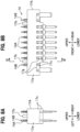
- the connector terminal body 17A has terminal placement holes 17j, 17k (partially shown in FIG. 9A ) formed in the terminal main body 17a, and the press-fit terminals 14 placed in these terminal placement holes 17j, 17k are fixed by molten plastic resin.
- the terminal placement holes 17j, 17k are pre-formed when the terminal main body 17a is resin molded.
- the terminal placement hole 17j is a hole for placing the straight shaped press-fit terminal 14A.
- the press-fit terminal 14A is inserted into the terminal placement hole 17j from the lower side of the terminal main body 17a.
- the terminal placement hole 17k is a hole for placing the crank-shaped press-fit terminal 14B.
- the press-fit terminal 14B is inserted into the terminal placement hole 17k from the lower side of the terminal main body 17a.
- each of the press-fit terminals 14A, 14B has an inlet hole 14b1 through which molten resin flows.
- melting recesses 17g are formed in the side surface of the terminal main body 17a at positions corresponding to each of the press-fit terminals 14A, 14B.
- Melting thickened portions 17c having a generally hemispherical shape protruding sideward are formed within the melting recesses 17g.
- the melting thickened portions 17c are formed at positions corresponding to the inlet holes 14b1 of the press-fit terminals 14A, 14B.
- the melting recesses 17g and the melting thickened portions 17c are similarly formed on the opposite left side of the terminal main body 17a.
- the press-fit terminals 14A, 14B are fixed to the terminal main body 17a during the manufacturing process of the connector terminal body 17A, the press-fit terminals 14A, 14B are inserted into the terminal placement holes 17j, 17k from below, and then heat is applied to the melting thickened portions 17c by clamping the connector terminal body 17A from both the right and left sides. This causes the melting thickened portions 17c to melt, and the molten resin flows into the inlet holes 14b1 of the press-fit terminals 14A, 14B. Accordingly, the press-fit terminals 14A, 14B are molded and fixed to the connector terminal body 17A.
- the press-fit terminals 14A, 14B can be fixed to the terminal main body 17a by a simple means of applying heat to the melting thickened portions 17c. This can simplify the manufacture of the connector terminal body 17A and enhance the productivity. Further, the options for manufacturing methods can be increased.
- FIGS. 10 and 11 show a connector terminal body 17B in another form, which is manufactured using a different manufacturing method from that of the above embodiment.
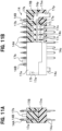
- FIGS. 10A and 10B show another form of connector terminal body used in the electrical component assembly according to the second embodiment of the present invention, in which FIG. 10A is a front view and FIG. 10B is a side view.
- FIGS. 11A and 11B are cross-sectional views of the another form of connector terminal body, in which FIG. 11A is a cross-sectional view taken along the line XI-XI of FIG. 10B and FIG. 11B is a partial cross-sectional side view.
- the connector terminal body 17B includes a terminal main body 17a, and a plug main body 17m attached to the lower portion of the terminal main body 17a.
- recess-shaped engagement portions 17e are formed at front and rear portions of the terminal main body 17a.
- hook portions 17f are formed at front and rear portions of the plug main body 17m. The hook portions 17f are engageable with the engagement portions 17e of the terminal main body 17a.
- the plug main body 17m is fixed to the terminal main body 17a by engaging the hook portions 17f with the engagement portions 17e of the terminal main body 17a.
- the terminal placement holes 17j, 17k are formed in the terminal main body 17a.
- plug-side placement holes 17n communicating with the terminal placement holes 17j and plug-side placement holes 17p communicating with the terminal placement holes 17k are formed in the plug main body portion 17m.
- the plug-side placement holes 17n, 17p are shaped to correspond to the lower portions of the press-fit terminals 14A, 14B, and has retaining portions 17r, 17s for holding widened portions 14n, 14p of the press-fit terminals 14A, 14B.
- the retaining portions 17r, 17s abut on the widened portions 14n, 14p of the press-fit terminals 14A, 14B from below to prevent the press-fit terminals 14A, 14B from being come off.
- the press-fit terminals 14A, 14B are fixed as follows: First, the press-fit terminals 14A, 14B are inserted into the terminal placement holes 17j, 17k of the terminal main body 17a from below. Then, the plug main body 17m is moved closer to the terminal main body 17a from below, and the upper surface of the plug main body 17m is brought into contact with the lower surface of the terminal main body 17a while inserting the lower portions 14c of the press-fit terminals 14A, 14B into the plug-side placement holes 17n, 17p.
- the press-fit terminals 14A, 14B can be fixed to the terminal main body 17a by a simple means of attaching the plug main body 17m to the terminal main body 17a and engaging them. This can simplify the manufacture of the connector terminal body 17B and enhance the productivity. Further, the options for manufacturing methods can be increased.
- the press-fit terminals 14 are used as an example of the connecting terminals.
- the connecting terminals are not limited to this specific configuration and may be any other connecting terminals.
- the connector terminal body 17 (electrical component) is provided with the fixing projections 17b, and the control board 11 has fixing holes 18.
- the connector terminal body 17 (electrical component) may have fixing holes, and the control board 11 may have fixing projections.
- the terminal main body 17a of the connector terminal body 17 is erected and fixed on the control board 11.
- the present invention is not limited to this specific configuration.
- the coil assemblies 15 and the bus bar terminal body 16 may be erected and fixed on the control board 11.
- control board 11 is fitted into the housing 2 and fixed to the housing 2 by heat staking.
- the method of fixing the control board 11 is not limited to this, and various fixing methods can be adopted.
- the electrical component assembly 1 is fixed to the base body 110 after the electrical component assembly 1 is assembled.
- the present invention is not limited to this specific configuration.
- the housing 2 may be attached to the base body 110 first, and then the control board assembly 3 may be mounted in the housing 2.
Landscapes
- Physics & Mathematics (AREA)
- Engineering & Computer Science (AREA)
- Electromagnetism (AREA)
- Fluid Mechanics (AREA)
- Transportation (AREA)
- Mechanical Engineering (AREA)
- Power Engineering (AREA)
- Regulating Braking Force (AREA)
Abstract
Description
- The present invention relates to an electrical component assembly, a method of manufacturing the electrical component assembly, and a vehicle brake hydraulic pressure control device.
- Conventionally, it is known that vehicles such as motorcycles and four-wheeled vehicles are equipped in their brake system with a brake hydraulic pressure control device that controls brake hydraulic pressure acting on the wheel brakes. The vehicle brake hydraulic pressure control device includes a base body with an internal brake fluid passage and a solenoid valve attached to one surface of the base body. An electrical component assembly is attached to one surface of the base body; the electrical component assembly includes a coil assembly, a bus bar terminal body, and a connector terminal body as electrical components, covered by a housing. The electrical components such as the coil assembly are connected to a control board disposed in the housing.
- A known method for mounting the control board in the housing is disclosed in
Patent Literature 1. InPatent Literature 1, the method involves mounting the electrical components in the housing in advance, aligning each of the through-holes of the control board with the tip end portion of each of the connecting terminals of the preassembled electrical components, and pushing the control board toward the electrical components. This enables the connecting terminals of the electrical components to be pressed into the through-holes of the control board, thereby electrically connecting the electrical components to the control board. - Patent Literature 1: JP
WO2018/151264 A1 - However, the assembling method disclosed in
Patent Literature 1 involves aligning the connecting terminals of the electrical components with the through-holes of the control board via the housing. As a result, the structure of the housing becomes complicated, and high dimensional accuracy and high assembly accuracy are required for each electrical component and the housing involved in the alignment, leading to increased costs. - The present invention aims to solve the aforementioned problem by providing an electrical component assembly, a method of manufacturing the electrical component assembly, and a vehicle brake hydraulic pressure control device, which can simplify the structure of the housing, enhance the ease of assembly of the electrical component, and reduce costs.
- To solve the above problem, an electrical component assembly according to the present invention is configured by mounting a control board assembly in a housing. The control board assembly comprises a control board and an electrical component mounted on the control board via connecting terminals.
- According to the present invention, it is possible to adopt an assembling method, in which an electrical component is mounted on a control board in advance to form a control board assembly, and then this control board assembly is mounted in a housing. Therefore, there is no need to use a conventional assembling method, which requires that an electrical component is mounted in a housing in advance, and then a control board is mounted in the housing while aligning connecting terminals of the electrical component with the control board (through-holes of the control board). Consequently, high dimensional accuracy and high assembly accuracy required for aligning the connecting terminals of the electrical component with the control board (through-holes of the control board) are not required, and the structure of the housing can be simplified.
- Further, since there is no need to insert-mold terminals for connecting the electrical component to the control board into the housing, the options for electrical connection methods can be increased.
- Further, since the electrical component assembly can be formed simply by mounting the control board assembly in the housing, the ease of assembly can be enhanced. As a result, the electrical component assembly according to the present invention can reduce costs.
- Preferably, the control board has fixing holes for fixing the electrical component, and the electrical component includes a terminal main body in which the connecting terminals are integrated with resin, and fixing projections provided on the terminal main body and fitted into the fixing holes.
- With this configuration, the terminal main body can be fixed to the control board by fitting the fixing projections of the terminal main body into the fixing holes of the control board. Further, since the terminal main body can be directly fixed to the control board, the attachment strength is improved, and even when an unintentional external force is applied to the terminal main body, the fixing projections resist the external force. This can effectively prevent an external force load from being applied to a portion where the connecting terminals and the control board are electrically connected.
- Preferably, the connecting terminals are press-fit terminals inserted into through-holes formed in the control board.
- With this configuration, the electrical component and the control board can be easily connected, thereby enhancing the ease of assembly.
- The electrical component assembly preferably comprises: board positioning holes formed in the control board for fixing the control board to the housing; and housing-side projections formed on the housing for fixing the control board and fitted into the board positioning holes.
- With this configuration, the control board assembly can be fixed to the housing by fitting the housing-side projections of the housing into the board positioning holes of the control board. Therefore, the control board assembly can be easily mounted in the housing, thereby enhancing the ease of assembly.
- Preferably, the electrical component in the control board assembly is either one of a coil assembly for driving a solenoid valve, a bus bar terminal body connected to an electric motor, and a connector terminal body.
- With this configuration, a cost-reduced electrical component assembly can be obtained.
- A vehicle brake hydraulic pressure control device according to the present invention is equipped with the electrical component assembly as described above. The vehicle brake hydraulic pressure control device is connected between a master cylinder and a wheel brake to control brake hydraulic pressure acting on the wheel brake.
- With this configuration of the vehicle brake hydraulic pressure control device according to the present invention, the electrical component can be reliably connected to the control board, so that the quality of the product can be improved and the reliability of brake hydraulic pressure control by the device can be improved as well. Further, the vehicle brake hydraulic pressure control device can reduce costs.
- Further, the present invention provides a method of manufacturing the electrical component assembly as described above, comprising the steps of: an electrical component setting step of setting the electrical component on an assembly jig; an assembling step of setting the control board on the assembly jig, and electrically connecting the connecting terminals of the electrical component set on the assembly jig in the electrical component setting step to the control board to assemble the control board assembly; and a control board assembly setting step of setting the control board assembly assembled in the assembling step in the housing.
- The method of manufacturing the electrical component assembly according to the present invention allows for positioning of the electrical component using the assembly jig, so that the positioning accuracy of the electrical component is improved. Further, since the connecting terminals of the electrical component are connected to the control board using the assembly jig, high dimensional accuracy and high assembly accuracy for aligning the electrical component with the control board are not required. This can enhance the ease of assembly and reduce costs.
- Further, the present invention provides a method of manufacturing the electrical component assembly as described above, comprising the steps of: an electrical component setting step of setting the electrical component on an assembly jig; an assembling step of setting the control board on the assembly jig, and electrically connecting the connecting terminals of the electrical component set on the assembly jig in the electrical component setting step to the control board to assemble the control board assembly; and a control board assembly setting step of setting the control board assembly assembled in the assembling step in the housing, wherein the control board assembly setting step comprises the steps of: fitting the housing-side projections into the board positioning holes; and heat staking the housing-side projections.
- The method of manufacturing the electrical component assembly according to the present invention allows for positioning of the electrical component using the assembly jig, so that the positioning accuracy of the electrical component is improved. Further, since the connecting terminals of the electrical component are connected to the control board using the assembly jig, high dimensional accuracy and high assembly accuracy for aligning the electrical component with the control board are not required. This can enhance the ease of assembly and reduce costs.
- Further, the control board assembly can be reliably fixed to the housing by heat staking. Therefore, the control board assembly can be positioned to the housing with high precision.
- The electrical component assembly, the method of manufacturing an electrical component assembly, and the vehicle brake hydraulic pressure control device according to the present invention can simplify the structure of the housing, enhance the ease of assembly of the electrical component, and reduce costs.
-
-
FIG. 1 is a perspective view showing a vehicle brake hydraulic pressure control device, in which an electrical component assembly according to a first embodiment of the present invention is mounted. -
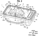
FIG. 2 is a perspective view showing the electrical component assembly according to the first embodiment of the present invention. -
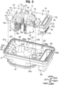
FIG. 3 is a perspective view showing how a control board assembly is mounted in a housing in the electrical component assembly according to the first embodiment of the present invention. -
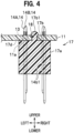
FIG. 4 is an enlarged cross-sectional view taken along the line IV-IV ofFIG. 3 . -
FIG. 5 is a perspective view showing an assembly jig used for assembling the control board assembly of the electrical component assembly according to the first embodiment of the present invention. -
FIG. 6 is a perspective view showing the assembly jig with electrical components mounted thereon. -
FIG. 7 is a perspective view showing the state in which a control board is mounted on the assembly jig with the electrical components mounted thereon. -
FIGS. 8A and 8B show a connector terminal body used in an electrical component assembly according to a second embodiment of the present invention, in whichFIG. 8A is a front view andFIG. 8B is a side view. -
FIG. 9A and 9B are cross-sectional views of the connector terminal body, in whichFIG. 9A is a cross-sectional view taken along the line IX-IX ofFIG. 8B andFIG. 9B is partial cross-sectional side view. -
FIGS. 10A and 10B show another form of connector terminal body used in the electrical component assembly according to the second embodiment of the present invention, in whichFIG. 10A is a front view andFIG. 10B is a side view. -
FIGS. 11A and 11B are cross-sectional views of the another form of connector terminal body, in whichFIG. 11A is a cross-sectional view taken along the line XI-XI ofFIG. 10B andFIG. 11B is a partial cross-sectional side view. -
FIG. 12 is an exploded perspective view showing another assembling method of the control board assembly. - Hereinafter, embodiments of the present invention will be described in detail with reference to the accompanying drawings as appropriate. In the following description, the same reference signs will be used for identical elements, and duplicated descriptions will be omitted. In the following description, an electrical component assembly that functions as a component of a vehicle brake hydraulic pressure control device will be described. However, this is not intended to limit the application of the electrical component assembly. When referring to front, rear, right, left, upper, and lower directions of a vehicle brake hydraulic pressure control device, an electrical component assembly, and a control board assembly, the reference is made based on the state where a control board is placed on electrical components (directions shown in
FIG. 1 , etc.). However, this is not intended to limit each direction. These directions do not necessarily correspond to the front, rear, right, left, upper, and lower directions of the electrical component assembly when in use (when mounted on a vehicle, etc.). - A vehicle brake hydraulic
pressure control device 100 is connected between a master cylinder (not shown) and wheel brakes to control brake hydraulic pressure acting on the wheel brakes. - As seen in
FIG. 1 , the vehicle brake hydraulicpressure control device 100 includes abase body 110 and anelectrical component assembly 1 attached to one surface of thebase body 110.Solenoid valves 120 corresponding to brake systems mounted on a vehicle, various sensors such as pressure sensors (not shown), an electric motor M, and a reciprocating pump P are attached to thebase body 110. Theelectrical component assembly 1 functions as an electronic control unit that detects the behavior of the vehicle body and controls the opening and closing of thesolenoid valves 120 and the operation of the electric motor M. - The
base body 110 is a metal component formed in a generally rectangular prism shape, in which brake fluid paths (oil paths), not shown, are formed. Ports and the like for connecting the piping that leads to the wheel brakes are formed at an outer surface (not shown) of thebase body 110. The vehicle brake hydraulicpressure control device 100 varies the brake fluid pressure within the brake fluid passages by operating thesolenoid valves 120 and the electric motor M through thecontrol board 11 in theelectrical component assembly 1, based on the behavior of the vehicle. - As seen in
FIG. 2 , theelectrical component assembly 1 includes ahousing 2 made of plastic resin and acontrol board assembly 3 mounted in thehousing 2. Thehousing 2 is a box body integrally fixed to an upper surface of the base body 110 (seeFIG. 1 ) by means such as screw fastening. As seen inFIG. 1 , thehousing 2 houses thecontrol board assembly 3 and also houses thesolenoid valves 120 protruding from thebase body 110 and a motor bus bar (not shown). - As seen in
FIG. 3 , thehousing 2 is open at its upper surface side and lower surface side ofFIG. 3 . The upper surface side is the surface opposite the base body 110 (seeFIG. 1 , the same applies hereinafter), where a lid member (not shown) to be described later will be attached. The lower surface side is thebase body 110 side. Thehousing 2 includes a plate-shapedbottom wall portion 24, a lid member-sideperipheral wall portion 25 provided on the upper surface side of thebottom wall portion 24, and a base body-sideperipheral wall portion 21 provided on the lower surface side of thebottom wall portion 24. - The
bottom wall portion 24 has a generally rectangular outline that is larger in the right-left direction than in the front-rear direction, as shown in the figure. The lid member-sideperipheral wall portion 25 extends upward from the peripheral edge portion of thebottom wall portion 24 and has a generally rectangular outer shape. A base body-side housing chamber 25a is formed inside the lid member-sideperipheral wall portion 25. The base body-side housing chamber 25a is configured to house upper parts of electrical components such as thecontrol board 11 having a generally rectangular shape, and coil assembles 15. - It is noted that an upper opening portion of the lid member-side
peripheral wall portion 25 is sealed with a lid member (not shown) made of plastic resin. The lid member is fixed to the upper opening portion of the lid member-sideperipheral wall portion 25 by means of welding, adhesion, screw fastening, or other means. - The base body-side
peripheral wall portion 21 extends downward in the figure from a lower surface of thebottom wall portion 24, and has a generally octagonal outer shape (partially shown). The base body-sideperipheral wall portion 21 forms a base body-side housing chamber 21a, into which thecoil assemblies 15 are housed. The inner surface shape of the base body-sideperipheral wall portion 21 conforms to the outer surface shape of thecoil assemblies 15. - A generally cylindrical first protruding
portion 130 configured to protrude frontward is formed on an inner surface of a rear wall of the base body-sideperipheral wall portion 21. A circularhollow portion 131 that penetrates in the upper-lower direction shown in the figure is formed inside the first protrudingportion 130. Thehollow portion 131 serves as a housing hole to house the busbar terminal body 16. - A generally cylindrical second protruding
portion 24a configured to protrude toward the right in the figure is formed on an inner surface of a left wall in the figure of the base body-sideperipheral wall portion 21. Further, a generally cylindrical third protrudingportion 24b configured to protrude toward the left in the figure is formed on an inner surface of a right wall in the figure of the base body-sideperipheral wall portion 21. Outer peripheral portions of the second protrudingportion 24a and the third protrudingportion 24b are arranged on the sides of fourcoil assemblies 15 housed in the base body-side housing chamber 21a, and serve as positioning members (movement regulating members) for thecoil assemblies 15. The secondprotruding portion 24a and the third protrudingportion 24b have hollowed-outportions 24c formed to penetrate in the upper-lower direction of the figure. - A connector terminal
body housing chamber 26a is formed on the right side in the figure of thebottom wall portion 24. The connector terminalbody housing chamber 26a extends through thebottom wall portion 24 in the upper-lower direction of the figure. The connector terminalbody housing chamber 26a has a generally rectangular shape that is larger in the front-rear direction than in the right-left direction of the figure. The connector terminalbody housing chamber 26a is defined by a base body-side coilperipheral wall portion 26 extending upward from the upper surface of thebottom wall portion 24, and a connector-side coilperipheral wall portion 22 extending downward from the lower surface of thebottom wall portion 24. Aconnector terminal body 17 is disposed in the connector terminalbody housing chamber 26a. - Housing-
side projections 23 for positioning and fixing thecontrol board 11 rise at each front, rear, right, and left portions of thebottom wall portion 24. Each housing-side projection 23 has a cylindrical shape that is fitted into corresponding board positioning holes 12 formed in thecontrol board 11. The housing-side projections 23 shown inFIG. 2 have theirhead portions 23a formed into hemispherical shapes by heat caulking. Thehead portions 23a may have various shapes as long as it can fix thecontrol board 11. - As seen in
FIG. 3 , thecontrol board assembly 3 includes thecontrol board 11, thecoil assemblies 15, the busbar terminal body 16, and theconnector terminal body 17 as electrical components mounted on thecontrol board 11. Thecoil assemblies 15, the busbar terminal body 16, and theconnector terminal body 17 are electrically connected to thecontrol board 11 via press-fit terminals 14 as connecting terminals. In the following, each of thecoil assemblies 15, the busbar terminal body 16, and theconnector terminal body 17 may be referred to simply as an electrical component. - The
control board 11 is a generally rectangular board body on which electrical circuits are printed and electrical components such as semiconductor chips are mounted. A plurality of through-holes 13 are formed in thecontrol board 11. The press-fit terminals 14 of each of thecoil assemblies 15, the busbar terminal body 16, and theconnector terminal body 17 are inserted into the through-holes 13 and pressed against hole walls of the through-holes 13. Thecontrol board 11 performs control based on information obtained from sensors (not shown) provided in the vehicle and programs stored in advance. To be more specific, thecontrol board 11 controls the energization of thecoil assemblies 15 and the electric motor M, thereby controlling the opening and closing operation of thesolenoid valves 120 and the driving of the electric motor M. Sensors include various types such as pressure sensors, angular velocity sensors, and acceleration sensors. - The
coil assembly 15 includes abobbin 15a made of plastic resin, acoil 15b wound around thebobbin 15a, and ayoke 15c attached to thebobbin 15a. Press-fit terminals 14 rise from the base body-side end portion of thebobbin 15a. Proximal portions of the press-fit terminals 14 are embedded in thebobbin 15a by molding. Fourcoil assemblies 15 are provided in total, corresponding to the positions where thesolenoid valves 120 are located, and as seen inFIG. 1 , eachcoil assembly 15 is housed in thehousing 2, surrounding thesolenoid valve 120. Eachcoil assembly 15 is configured to generate a magnetic field around eachsolenoid valve 120 by energizing thecoil 15b from thecontrol board 11 through the press-fit terminals 14, thereby driving thesolenoid valve 120. - As seen in
FIG. 3 , the busbar terminal body 16 has a bottomed cylindrical tubular portion made of plastic resin. Press-fit terminals 14 rise at the base body-side end portion of the tubular portion of the busbar terminal body 16. Proximal portions of the press-fit terminals 14 are embedded in the tubular portion of the busbar terminal body 16 by molding. The busbar terminal body 16 is mounted on thecontrol board 11 corresponding to thehollow portion 131 of the base body-sideperipheral wall portion 21 of thehousing 2, and is housed in thehollow portion 131 when thecontrol board assembly 3 is mounted in thehousing 2. The busbar terminal body 16 internally contains a connection portion (not shown), to which the bus bar from the electric motor M is connected. The busbar terminal body 16 supplies power from thecontrol board 11 to the electric motor M. - As seen in
FIG. 4 , theconnector terminal body 17 has a terminalmain body 17a as a resin member, in which a plurality of press-fit terminals 14 are integrated by molding. As seen inFIG. 3 , the terminalmain body 17a has a generally prismatic shape extending in the front-rear direction of the figure. A lid member-side surface 17d of the terminalmain body 17a is entirely flat and abuts on a base body-side surface 11a of thecontrol board 11. A pair of front andrear fixing projections 17b protrude from the lid member-side surface 17d of the terminalmain body 17a (only one is shown inFIG. 4 ). Each fixingprojection 17b has a cylindrical shape that can be fitted into a fixinghole 18 formed in the control board 11 (seeFIGS. 8A and 8B ). The fixingprojection 17b shown inFIG. 4 shows the state in which the head portion 17b1 is formed into a hemispherical shape by heat staking. The head portion 17b1 may have various shapes as long as they can fix theconnector terminal body 17. - In the
connector terminal body 17, a plurality of press-fit terminals 14 are arranged in two rows on the right and left sides of the terminalmain body 17a, spaced apart in the front-rear direction ofFIG. 3 . Each press-fit terminal 14 has a central portion in the upper-lower direction ofFIG. 3 that is embedded (molded) in the terminalmain body 17a, while its upper and lower portions are exposed. Each press-fit terminal 14 has an inlet hole 14b1 through which molded resin flows. Theconnector terminal body 17 according to this embodiment has two types of terminals as press-fit terminals 14, including press-fit terminals 14B located at the front and rear end portions of the terminalmain body 17a, and press-fit terminals 14A located at other parts of the terminalmain body 17a. - In this
connector terminal body 17, the plurality of press-fit terminals 14 are inserted into the through-holes 13 and the fixingprojections 17b are fitted into the fixing holes 18, followed by securing the head portions of the fixingprojections 17b to the fixing holes 18 by welding or adhesion. This allows for fixing the terminalmain body 17a to the lower surface of thecontrol board 11. Then, theconnector terminal body 17 is housed in the connector terminalbody housing chamber 26a of thehousing 2 during the process of mounting thecontrol board assembly 3 in thehousing 2. A connector (not shown) of the vehicle is connected to theconnector terminal body 17. - The terminal
main body 17a may be configured such that the lid member-side surface 17d does not entirely abut on the base body-side surface 11a of thecontrol board 11, and a part of the lid member-side surface 17d abuts on the base body-side surface 11a. - Next, the manufacturing method of the
electrical component assembly 1 will be described. -
FIG. 5 is a perspective view showing an assembly jig used for manufacturing thecontrol board assembly 3 that constitutes theelectrical component assembly 1.FIG. 6 is a perspective view showing the assembly jig with electrical components mounted thereon.FIG. 7 is a perspective view showing the state in which the control board is mounted on the assembly jig with the electrical components mounted thereon. - An
assembly jig 50 is a jig used for mounting electric components on thecontrol board 11. As seen inFIG. 5 , theassembly jig 50 includes a plate-like base 51,board support portions coil support portions 54, a bus bar terminalbody support portion 55, and a connector terminalbody support portion 56. Theboard support portions coil support portions 54, the bus bar terminalbody support portion 55, and the connector terminalbody support portion 56 are integrally provided on thebase 51. - As viewed in plan view, the
base 51 has a generally rectangular shape that is larger in the right-left direction than in the front-rear direction. Theboard support portion 52, which has a plate shape extending in the front-rear direction, is provided along the left edge portion of thebase 51. The upper surface of theboard support portion 52 has aplacement surface 52a on which the left edge portion of the control board 11 (seeFIG. 7 ) is placed.Board support portions 53, which have a columnar shape, are provided in pairs at the front edge portion and the rear edge portion of thebase 51. The upper surfaces of theboard support portions 53 haveplacement surfaces 53a on which the front edge portion and the rear edge portion of thecontrol board 11 are placed. - The
coil support portions 54 have a cylindrical shape. A total of fourcoil support portions 54 are provided in predetermined positions on thebase 51. Eachcoil support portion 54 is formed to be insertable into abobbin 15a of the coil assembly 15 (seeFIG. 6 ). Thebase 51 hasrecesses 54a formed around the base body-side end portions of thecoil support portions 54. Eachrecess 54a has a shape into which the base body-side end portion of thecoil assembly 15 can be fitted. With this configuration of thecoil support portions 54 and therecesses 54a, thecoil assemblies 15 are positioned on thebase 51, allowing for the alignment of the press-fit terminals 14 of thecoil assemblies 15. - The bus bar terminal
body support portion 55 has a cylindrical shape. The bus bar terminalbody support portion 55 is provided on the rear end portion side of the base 51 at approximately the center in the right-left direction of thebase 51. The bus bar terminalbody support portion 55 is formed to be insertable into the busbar terminal body 16. The connector terminalbody support portion 56 has a bottomed rectangular frame shape that is larger in the front-rear direction than in the right-left direction, and is provided along the right edge portion of thebase 51. Ahousing portion 56a is formed inside the connector terminalbody support portion 56. Thehousing portion 56a is sized to house theconnector terminal body 17. The bottom portion of thehousing portion 56a hasinsertion holes 56b, into which part of the press-fit terminals 14 of theconnector terminal body 17 are inserted. - The manufacturing method of the
control board assembly 3 includes an electrical component setting step, an assembling step, and a control board assembly setting step. - The electrical component setting step involves setting electrical components on an
assembly jig 50. - An example of the specific procedure is as follows: As seen in
FIG. 6 , first,coil assemblies 15 are inserted overcoil support portions 54, and the base body-side end portions of thecoil assemblies 15 are fitted into therecesses 54a. Next, the busbar terminal body 16 is fitted over the bus bar terminalbody support portion 55, and two press-fit terminals 14 thereof are oriented such that they are aligned in the right-left direction. Then, theconnector terminal body 17 is moved closer to thehousing portion 56a of the connector terminalbody support portion 56, and the press-fit terminals 14 are inserted into the insertion holes 56b to house theconnector terminal body 17 within thehousing portion 56a. - The assembling step involves setting the
control board 11 on theassembly jig 50, and electrically connecting the press-fit terminals 14 of each electrical component to thecontrol board 11 to assemble thecontrol board assembly 3. - An example of the specific procedure is as follows: As seen in
FIG. 7 , thecontrol board 11 is moved closer to theassembly jig 50 from above, and tip end portions of the press-fit terminals 14 of each electrical component are aligned with the through-holes 13 of thecontrol board 11 while aligning thecontrol board 11 such that each portion of thecontrol board 11 is placed on the left-side placement surface 52a and the right-side front and rear placement surfaces 53a. Once the alignment of thecontrol board 11 is completed, thecontrol board 11 is pushed toward thebase 51. This causes the tip end portions of the press-fit terminals 14 of each electrical component to be inserted into the through-holes 13 of thecontrol board 11 and pressed against the hole walls of the through-holes 13. Further, the fixingprojections 17b of theconnector terminal body 17 are fitted into the fixing holes 18 of thecontrol board 11. The fixingprojections 17b are heat staked to form the head portions 17b1, 17b1, and theconnector terminal body 17 is fixed to thecontrol board 11. Accordingly, thecontrol board assembly 3, in which the electrical components are mounted on thecontrol board 11, is completed. - The control board assembly setting step involves setting the thus assembled
control board assembly 3 in thehousing 2 for assembling. The control board assembly setting step involves staking to be described later. - In the control board assembly setting step, as seen in
FIG. 3 , thecontrol board assembly 3 is moved closer to the base body-side housing chamber 25a from above thehousing 2, and thecoil assemblies 15 mounted on the lower surface of thecontrol board 11 are housed in the base body-side housing chamber 21a from the base body-side housing chamber 25a while the busbar terminal body 16 is housed in thehollow portion 131 from the base body-side housing chamber 25a. Further, theconnector terminal body 17 is housed in the connector terminalbody housing chamber 26a. - Then, the board positioning holes 12 of the
control board 11 are aligned with the housing-side projections 23 of thehousing 2, and thecontrol board 11 is pushed (downward) toward thebottom wall portion 24. This causes the housing-side projections 23 to be fitted into the board positioning holes 12, and thecontrol board assembly 3 is mounted in the housing 2 (seeFIG. 2 ). - The staking step involves securely fixing the control board assembly 3 (the control board 11) to the
housing 2 by heat staking. - In the staking step, the housing-
side projections 23 fitted into the board positioning holes 12 are melted to heat stake the housing-side projections 23. In other words, the housing-side projections 23 protruding from the board positioning holes 12 are deformed while applying heat to form a portion having a diameter larger than that of theboard positioning hole 12. As a result, the housing-side projections 23 act as a retainer, so that the control board assembly 3 (the control board) is securely fixed to thehousing 2. This ensures that the control board assembly 3 (the control board) is securely fixed to thehousing 2. - According to the
electrical component assembly 1 of this embodiment described above, it is possible to adopt an assembling method, in which electrical components are mounted on thecontrol board 11 in advance to form thecontrol board assembly 3, and then thiscontrol board assembly 3 is mounted in thehousing 2. Therefore, there is no need to use a conventional assembling method, which requires that the electrical components are mounted in the housing in advance, and then the control board is mounted in the housing while aligning connecting terminals (press-fit terminals) of the electrical components with the control board (through-holes of the control board). Consequently, high dimensional accuracy and high assembly accuracy required for aligning the press-fit terminals 14 of the electrical components with the control board 11 (through-holes of the control board) are not required, and the structure of thehousing 2 can be simplified. - Since there is no need to insert-mold terminals for connecting the electrical components to the
control board 11 into thehousing 2, the options for electrical connection methods can be increased. - Further, since the
electrical component assembly 1 can be formed simply by mounting thecontrol board assembly 3 in thehousing 2, the ease of assembly can be enhanced. As a result, theelectrical component assembly 1 according to the present invention can reduce costs. - The terminal
main body 17a can be mounted on thecontrol board 11 by fitting the fixingprojections 17b of the terminalmain body 17a into the fixing holes 18 of thecontrol board 11. Further, since the terminalmain body 17a can be directly fixed to thecontrol board 11, the attachment strength is improved, and even when an unintentional external force is applied to the terminalmain body 17a, the fixingprojections 17b resist the external force. This can effectively prevent an external force load from being applied to a portion where the press-fit terminals 14 and the through-holes 13 are electrically connected. - Since the press-
fit terminals 14 are used as connecting terminals, the electrical components and thecontrol board 11 can be easily connected, thereby enhancing the ease of assembly. - The
control board assembly 3 can be fixed to thehousing 2 by fitting the housing-side projections 23 of thehousing 2 into the board positioning holes 12 of thecontrol board 11. Therefore, thecontrol board assembly 3 can be easily mounted in thehousing 2, thereby enhancing the ease of assembly. - Since the electrical components are the
coil assemblies 15, the busbar terminal body 16, and theconnector terminal body 17, a cost-reducedelectrical component assembly 1 can be obtained. - Further, according to the vehicle brake hydraulic
pressure control device 100 of the present invention, the coil assemblies 15 (electrical components) can be reliably connected to thecontrol board 11, so that the quality of the product can be improved and the reliability of brake hydraulic pressure control by the device can be improved as well. Further, the vehicle brake hydraulicpressure control device 100 can reduce costs. - Further, the method of manufacturing the
electrical component assembly 1 according to the present invention allows for positioning of the electrical components using theassembly jig 50, so that the positioning accuracy of the electrical components is improved. Further, since the press-fit terminals 14 of the electrical components are connected to thecontrol board 11 using theassembly jig 50, high dimensional accuracy and high assembly accuracy for aligning the electrical components with thecontrol board 11 are not required. This can enhance the ease of assembly and reduce costs. - Further, the method of manufacturing the
electrical component assembly 1 allows for reliably fixing thecontrol board assembly 3 to thehousing 2 by the control board assembly setting step. This can enhance the ease of assembly and reduce costs. - Next, an electrical component assembly according to the second embodiment will be described. The difference between this embodiment and the first embodiment is that a
connector terminal body 17A manufactured using a different method from that of the first embodiment is used in this embodiment. -
FIGS. 8A and 8B show a connector terminal body used in an electrical component assembly according to the second embodiment of the present invention, in whichFIG. 8A is a front view andFIG. 8B is a side view.FIG. 9A and 9B are cross-sectional views of the connector terminal body, in whichFIG. 9A is a cross-sectional view taken along the line IX-IX ofFIG. 8B andFIG. 9B is partial cross-sectional side view. - As seen in
FIGS. 9A and 9B , theconnector terminal body 17A according to this embodiment hasterminal placement holes FIG. 9A ) formed in the terminalmain body 17a, and the press-fit terminals 14 placed in theseterminal placement holes terminal placement holes main body 17a is resin molded. - The
terminal placement hole 17j is a hole for placing the straight shaped press-fit terminal 14A. The press-fit terminal 14A is inserted into theterminal placement hole 17j from the lower side of the terminalmain body 17a. On the other hand, theterminal placement hole 17k is a hole for placing the crank-shaped press-fit terminal 14B. The press-fit terminal 14B is inserted into theterminal placement hole 17k from the lower side of the terminalmain body 17a. As seen inFIG. 9B , each of the press-fit terminals - As seen in
FIG. 8B , generallyrectangular melting recesses 17g are formed in the side surface of the terminalmain body 17a at positions corresponding to each of the press-fit terminals portions 17c having a generally hemispherical shape protruding sideward are formed within the melting recesses 17g. The melting thickenedportions 17c are formed at positions corresponding to the inlet holes 14b1 of the press-fit terminals portions 17c are similarly formed on the opposite left side of the terminalmain body 17a. - When the press-
fit terminals main body 17a during the manufacturing process of theconnector terminal body 17A, the press-fit terminals terminal placement holes portions 17c by clamping theconnector terminal body 17A from both the right and left sides. This causes the melting thickenedportions 17c to melt, and the molten resin flows into the inlet holes 14b1 of the press-fit terminals fit terminals connector terminal body 17A. - According to this embodiment, the press-
fit terminals main body 17a by a simple means of applying heat to the melting thickenedportions 17c. This can simplify the manufacture of theconnector terminal body 17A and enhance the productivity. Further, the options for manufacturing methods can be increased. -
FIGS. 10 and11 show aconnector terminal body 17B in another form, which is manufactured using a different manufacturing method from that of the above embodiment. -
FIGS. 10A and 10B show another form of connector terminal body used in the electrical component assembly according to the second embodiment of the present invention, in whichFIG. 10A is a front view andFIG. 10B is a side view.FIGS. 11A and 11B are cross-sectional views of the another form of connector terminal body, in whichFIG. 11A is a cross-sectional view taken along the line XI-XI ofFIG. 10B andFIG. 11B is a partial cross-sectional side view. - As seen in
FIGS. 10A and 10B andFIGS. 11A and 11B , theconnector terminal body 17B includes a terminalmain body 17a, and a plugmain body 17m attached to the lower portion of the terminalmain body 17a. As seen inFIG. 11B , recess-shapedengagement portions 17e are formed at front and rear portions of the terminalmain body 17a. On the other hand,hook portions 17f are formed at front and rear portions of the plugmain body 17m. Thehook portions 17f are engageable with theengagement portions 17e of the terminalmain body 17a. The plugmain body 17m is fixed to the terminalmain body 17a by engaging thehook portions 17f with theengagement portions 17e of the terminalmain body 17a. - As with the above embodiment, the
terminal placement holes main body 17a. On the other hand, plug-side placement holes 17n communicating with theterminal placement holes 17j and plug-side placement holes 17p communicating with the terminal placement holes 17k are formed in the plugmain body portion 17m. The plug-side placement holes fit terminals portions portions fit terminals portions portions fit terminals fit terminals - In the manufacturing process of the
connector terminal body 17B as described above, the press-fit terminals fit terminals terminal placement holes main body 17a from below. Then, the plugmain body 17m is moved closer to the terminalmain body 17a from below, and the upper surface of the plugmain body 17m is brought into contact with the lower surface of the terminalmain body 17a while inserting thelower portions 14c of the press-fit terminals side placement holes hook portions 17f of the plugmain body 17m to be engaged with theengagement portions 17e of the terminalmain body 17a, so that the plugmain body 17m is fixed to the terminalmain body 17a and the press-fit terminals - According to this embodiment, the press-
fit terminals main body 17a by a simple means of attaching the plugmain body 17m to the terminalmain body 17a and engaging them. This can simplify the manufacture of theconnector terminal body 17B and enhance the productivity. Further, the options for manufacturing methods can be increased. - Although the embodiments of the present invention have been described above, the present invention is not limited to the above-described embodiments and can be appropriately modified without departing from the gist of the invention.
- In the above embodiments, the press-
fit terminals 14 are used as an example of the connecting terminals. However, the connecting terminals are not limited to this specific configuration and may be any other connecting terminals. - Further, in the above embodiments, the connector terminal body 17 (electrical component) is provided with the fixing
projections 17b, and thecontrol board 11 has fixingholes 18. However, as an alternative, the connector terminal body 17 (electrical component) may have fixing holes, and thecontrol board 11 may have fixing projections. - Further, in the above embodiments, the terminal
main body 17a of theconnector terminal body 17 is erected and fixed on thecontrol board 11. However, the present invention is not limited to this specific configuration. Thecoil assemblies 15 and the busbar terminal body 16 may be erected and fixed on thecontrol board 11. - Further, in the above embodiments, the
control board 11 is fitted into thehousing 2 and fixed to thehousing 2 by heat staking. However, the method of fixing thecontrol board 11 is not limited to this, and various fixing methods can be adopted. - Further, in the first embodiment, the
electrical component assembly 1 is fixed to thebase body 110 after theelectrical component assembly 1 is assembled. However, the present invention is not limited to this specific configuration. As seen inFIG. 12 , thehousing 2 may be attached to thebase body 110 first, and then thecontrol board assembly 3 may be mounted in thehousing 2. -
- 1
- electrical component assembly
- 2
- housing
- 3
- control board assembly
- 11
- control board
- 12
- board positioning hole
- 13
- through-hole
- 14
- press-fit terminal (connecting terminal)
- 15
- coil assembly (electrical component)
- 16
- bus bar terminal body (electrical component)
- 17
- connector terminal body (electrical component)
- 17A, 17B
- connector terminal body (electrical component)
- 17a
- terminal main body (resin member)
- 17b
- fixing projection
- 17b1
- head portion
- 18
- fixing hole
- 23
- housing-side projection
- 23a
- head portion
- 100
- vehicle brake hydraulic pressure control device
Claims (8)
- An electrical component assembly comprising a control board assembly mounted in a housing, wherein
the control board assembly comprises a control board and an electrical component mounted on the control board via connecting terminals. - The electrical component assembly according to claim 1, whereinthe control board has fixing holes for fixing the electrical component, andthe electrical component includes a terminal main body in which the connecting terminals are integrated with resin, and fixing projections provided on the terminal main body and fitted into the fixing holes.
- The electrical component assembly according to claim 1 or 2, wherein
the connecting terminals are press-fit terminals inserted into through-holes formed in the control board. - The electrical component assembly according to any one of claims 1 to 3, further comprising:board positioning holes formed in the control board for fixing the control board to the housing; andhousing-side projections formed on the housing for fixing the control board and fitted into the board positioning holes.
- The electrical component assembly according to any one of claims 1 to 4, wherein
the electrical component in the control board assembly is either one of a coil assembly for driving a solenoid valve, a bus bar terminal body connected to an electric motor, and a connector terminal body. - A vehicle brake hydraulic pressure control device equipped with the electrical component assembly according to any one of claims 1 to 5, wherein
the vehicle brake hydraulic pressure control device is connected between a master cylinder and a wheel brake to control brake hydraulic pressure acting on the wheel brake. - A method of manufacturing the electrical component assembly according to any one of claims 1 to 5, comprising the steps of:an electrical component setting step of setting the electrical component on an assembly jig;an assembling step of setting the control board on the assembly jig, and electrically connecting the connecting terminals of the electrical component set on the assembly jig in the electrical component setting step to the control board to assemble the control board assembly; anda control board assembly setting step of setting the control board assembly assembled in the assembling step in the housing.
- A method of manufacturing the electrical component assembly according to claim 4, comprising the steps of:an electrical component setting step of setting the electrical component on an assembly jig;an assembling step of setting the control board on the assembly jig, and electrically connecting the connecting terminals of the electrical component set on the assembly jig in the electrical component setting step to the control board to assemble the control board assembly; anda control board assembly setting step of setting the control board assembly assembled in the assembling step in the housing, whereinthe control board assembly setting step comprises the steps of:fitting the housing-side projections into the board positioning holes; andheat staking the housing-side projections.
Applications Claiming Priority (2)
| Application Number | Priority Date | Filing Date | Title |
|---|---|---|---|
| JP2022061056 | 2022-03-31 | ||
| PCT/JP2023/012864 WO2023190711A1 (en) | 2022-03-31 | 2023-03-29 | Electrical component assembly, electrical component assembly manufacturing method, and vehicle brake hydraulic pressure control device |
Publications (2)
| Publication Number | Publication Date |
|---|---|
| EP4502439A1 true EP4502439A1 (en) | 2025-02-05 |
| EP4502439A4 EP4502439A4 (en) | 2026-04-01 |
Family
ID=88202094
Family Applications (1)
| Application Number | Title | Priority Date | Filing Date |
|---|---|---|---|
| EP23780719.3A Pending EP4502439A4 (en) | 2022-03-31 | 2023-03-29 | ELECTRICAL COMPONENT ARRANGEMENT, MANUFACTURING METHOD FOR ELECTRICAL COMPONENT ARRANGEMENT AND HYDRAULIC PRESSURE CONTROL DEVICE FOR VEHICLE BRAKES |
Country Status (4)
| Country | Link |
|---|---|
| EP (1) | EP4502439A4 (en) |
| JP (1) | JP7675319B2 (en) |
| CN (1) | CN118900798A (en) |
| WO (1) | WO2023190711A1 (en) |
Families Citing this family (1)
| Publication number | Priority date | Publication date | Assignee | Title |
|---|---|---|---|---|
| DE102024106989A1 (en) * | 2024-03-12 | 2025-09-18 | Zf Cv Systems Global Gmbh | Electronically controllable pneumatic braking system for a commercial vehicle and commercial vehicle and method for operating the braking system |
Family Cites Families (5)
| Publication number | Priority date | Publication date | Assignee | Title |
|---|---|---|---|---|
| JP2000221368A (en) * | 1999-02-04 | 2000-08-11 | Nippon Telegr & Teleph Corp <Ntt> | Optical semiconductor mounting equipment |
| JP2008537517A (en) * | 2004-12-21 | 2008-09-18 | コンティネンタル・テーベス・アクチエンゲゼルシヤフト・ウント・コンパニー・オッフェネ・ハンデルスゲゼルシヤフト | Electrohydraulic pressure regulator for automotive brake systems |
| JP2012158228A (en) * | 2011-01-31 | 2012-08-23 | Advics Co Ltd | Solenoid control apparatus |
| JP2015160482A (en) * | 2014-02-26 | 2015-09-07 | 株式会社デンソー | Actuator for brake fluid pressure control |
| CN110447314B (en) * | 2017-02-17 | 2021-08-20 | 日信工业株式会社 | Electric component assemblies and brake hydraulic control devices for vehicles |
-
2023
- 2023-03-29 WO PCT/JP2023/012864 patent/WO2023190711A1/en not_active Ceased
- 2023-03-29 EP EP23780719.3A patent/EP4502439A4/en active Pending
- 2023-03-29 JP JP2024512695A patent/JP7675319B2/en active Active
- 2023-03-29 CN CN202380029211.5A patent/CN118900798A/en active Pending
Also Published As
| Publication number | Publication date |
|---|---|
| EP4502439A4 (en) | 2026-04-01 |
| CN118900798A (en) | 2024-11-05 |
| JPWO2023190711A1 (en) | 2023-10-05 |
| WO2023190711A1 (en) | 2023-10-05 |
| JP7675319B2 (en) | 2025-05-14 |
Similar Documents
| Publication | Publication Date | Title |
|---|---|---|
| JP5611332B2 (en) | Connecting element and fluid group | |
| US11167740B2 (en) | Coil assembly and brake control device | |
| US10940848B2 (en) | Electric component assembly, and brake fluid pressure control device for vehicle | |
| JPH10132122A (en) | Solenoid valve unit | |
| US6616249B2 (en) | Device for mounting coil assemblies of solenoid valves in electronically controlled brake systems | |
| CN115666974B (en) | Chassis component and method for producing such a chassis component | |
| WO2017159061A1 (en) | Electronic control device | |
| CN110382314B (en) | Electric component assemblies and brake hydraulic control devices for vehicles | |
| JP7675319B2 (en) | Electrical component assembly, manufacturing method of electrical component assembly, and vehicle brake fluid pressure control device | |
| JP4626846B2 (en) | Method of connecting solenoid and lead frame and assembly of solenoid and lead frame | |
| JP6917157B2 (en) | Coil assembly and brake control | |
| US11594840B2 (en) | Resin molded product | |
| JP2018131187A (en) | Electric component assembly and vehicle brake fluid pressure control device | |
| US10673184B2 (en) | Rigid electrical connection to strain sensitive sensing component | |
| US20040135428A1 (en) | Hydraulic unit for anti-lock automobile brake systems and method for producing the same | |
| JP5281608B2 (en) | Electronic control unit and vehicle brake hydraulic pressure control device | |
| JP2003341498A (en) | Electronic control unit | |
| KR20200138896A (en) | Solenoid coil assembly of solenoid valve of ESC for vehicles | |
| JP2011213264A (en) | Electronic control unit and brake fluid pressure control device for vehicle | |
| JP7737012B2 (en) | Hydraulic pressure control device and method for manufacturing the same. | |
| KR102484448B1 (en) | Coil Assembly for Breaking Vehicle And Brake Apparatus Having The Same | |
| CN106024271B (en) | Choke coil for brake control device | |
| JP2011068226A (en) | Method of manufacturing housing device, housing device, and brake fluid pressure control device for vehicle using the same | |
| US20190277872A1 (en) | Remote sensor construction via integrated vacuum manufacture process | |
| KR100484027B1 (en) | Coil assembly of solenoid valve for ABS |
Legal Events
| Date | Code | Title | Description |
|---|---|---|---|
| STAA | Information on the status of an ep patent application or granted ep patent |
Free format text: STATUS: THE INTERNATIONAL PUBLICATION HAS BEEN MADE |
|
| PUAI | Public reference made under article 153(3) epc to a published international application that has entered the european phase |
Free format text: ORIGINAL CODE: 0009012 |
|
| STAA | Information on the status of an ep patent application or granted ep patent |
Free format text: STATUS: REQUEST FOR EXAMINATION WAS MADE |
|
| 17P | Request for examination filed |
Effective date: 20241020 |
|
| AK | Designated contracting states |
Kind code of ref document: A1 Designated state(s): AL AT BE BG CH CY CZ DE DK EE ES FI FR GB GR HR HU IE IS IT LI LT LU LV MC ME MK MT NL NO PL PT RO RS SE SI SK SM TR |
|
| DAV | Request for validation of the european patent (deleted) | ||
| DAX | Request for extension of the european patent (deleted) | ||
| RAP3 | Party data changed (applicant data changed or rights of an application transferred) |
Owner name: ASTEMO, LTD. |
|
| A4 | Supplementary search report drawn up and despatched |
Effective date: 20260304 |
|
| RIC1 | Information provided on ipc code assigned before grant |
Ipc: F16K 31/06 20060101AFI20260226BHEP Ipc: H01F 7/06 20060101ALI20260226BHEP Ipc: H01F 7/16 20060101ALI20260226BHEP Ipc: B60T 8/36 20060101ALI20260226BHEP |