EP4502425A1 - Vehicular drive device - Google Patents
Vehicular drive device Download PDFInfo
- Publication number
- EP4502425A1 EP4502425A1 EP23852456.5A EP23852456A EP4502425A1 EP 4502425 A1 EP4502425 A1 EP 4502425A1 EP 23852456 A EP23852456 A EP 23852456A EP 4502425 A1 EP4502425 A1 EP 4502425A1
- Authority
- EP
- European Patent Office
- Prior art keywords
- specific
- radial direction
- bevel
- tubular
- bevel gear
- Prior art date
- Legal status (The legal status is an assumption and is not a legal conclusion. Google has not performed a legal analysis and makes no representation as to the accuracy of the status listed.)
- Pending
Links
Images

Classifications
-
- F—MECHANICAL ENGINEERING; LIGHTING; HEATING; WEAPONS; BLASTING
- F16—ENGINEERING ELEMENTS AND UNITS; GENERAL MEASURES FOR PRODUCING AND MAINTAINING EFFECTIVE FUNCTIONING OF MACHINES OR INSTALLATIONS; THERMAL INSULATION IN GENERAL
- F16H—GEARING
- F16H48/00—Differential gearings
- F16H48/06—Differential gearings with gears having orbital motion
- F16H48/08—Differential gearings with gears having orbital motion comprising bevel gears
-
- B—PERFORMING OPERATIONS; TRANSPORTING
- B60—VEHICLES IN GENERAL
- B60K—ARRANGEMENT OR MOUNTING OF PROPULSION UNITS OR OF TRANSMISSIONS IN VEHICLES; ARRANGEMENT OR MOUNTING OF PLURAL DIVERSE PRIME-MOVERS IN VEHICLES; AUXILIARY DRIVES FOR VEHICLES; INSTRUMENTATION OR DASHBOARDS FOR VEHICLES; ARRANGEMENTS IN CONNECTION WITH COOLING, AIR INTAKE, GAS EXHAUST OR FUEL SUPPLY OF PROPULSION UNITS IN VEHICLES
- B60K1/00—Arrangement or mounting of electrical propulsion units
-
- F—MECHANICAL ENGINEERING; LIGHTING; HEATING; WEAPONS; BLASTING
- F16—ENGINEERING ELEMENTS AND UNITS; GENERAL MEASURES FOR PRODUCING AND MAINTAINING EFFECTIVE FUNCTIONING OF MACHINES OR INSTALLATIONS; THERMAL INSULATION IN GENERAL
- F16H—GEARING
- F16H48/00—Differential gearings
- F16H48/38—Constructional details
- F16H48/40—Constructional details characterised by features of the rotating cases
-
- F—MECHANICAL ENGINEERING; LIGHTING; HEATING; WEAPONS; BLASTING
- F16—ENGINEERING ELEMENTS AND UNITS; GENERAL MEASURES FOR PRODUCING AND MAINTAINING EFFECTIVE FUNCTIONING OF MACHINES OR INSTALLATIONS; THERMAL INSULATION IN GENERAL
- F16H—GEARING
- F16H57/00—General details of gearing
- F16H57/02—Gearboxes; Mounting gearing therein
- F16H57/037—Gearboxes for accommodating differential gearings
-
- B—PERFORMING OPERATIONS; TRANSPORTING
- B60—VEHICLES IN GENERAL
- B60K—ARRANGEMENT OR MOUNTING OF PROPULSION UNITS OR OF TRANSMISSIONS IN VEHICLES; ARRANGEMENT OR MOUNTING OF PLURAL DIVERSE PRIME-MOVERS IN VEHICLES; AUXILIARY DRIVES FOR VEHICLES; INSTRUMENTATION OR DASHBOARDS FOR VEHICLES; ARRANGEMENTS IN CONNECTION WITH COOLING, AIR INTAKE, GAS EXHAUST OR FUEL SUPPLY OF PROPULSION UNITS IN VEHICLES
- B60K1/00—Arrangement or mounting of electrical propulsion units
- B60K2001/001—Arrangement or mounting of electrical propulsion units one motor mounted on a propulsion axle for rotating right and left wheels of this axle
-
- F—MECHANICAL ENGINEERING; LIGHTING; HEATING; WEAPONS; BLASTING
- F16—ENGINEERING ELEMENTS AND UNITS; GENERAL MEASURES FOR PRODUCING AND MAINTAINING EFFECTIVE FUNCTIONING OF MACHINES OR INSTALLATIONS; THERMAL INSULATION IN GENERAL
- F16H—GEARING
- F16H48/00—Differential gearings
- F16H48/38—Constructional details
- F16H48/40—Constructional details characterised by features of the rotating cases
- F16H2048/405—Constructional details characterised by features of the rotating cases characterised by features of the bearing of the rotating case
Definitions
- the present invention relates to a vehicle drive device including an input member drivingly connected to a driving force source, a pair of output shafts drivingly connected to wheels, a speed reducer that reduces the speed of rotation of the input member, and a differential gear device that distributes the rotation of the input member transmitted via the speed reducer to the pair of output shafts.
- Patent Document 1 An example of such a vehicle drive device is disclosed in Patent Document 1 below.
- signs used in Patent Document 1 are shown in parentheses.
- a differential gear device (5) of a vehicle drive device (1) of Patent Document 1 includes a differential case (50) and a differential gear mechanism housed in the differential case.
- the differential gear mechanism includes a shaft member (51) formed so as to extend along a radial direction, a first bevel gear (52) rotatably supported by the shaft member, and a pair of second bevel gears (54A, 54B) disposed separately on both axial sides of the shaft member (51) and meshing with the first bevel gear (52).
- One second bevel gear (54A) is connected to a first drive shaft (9A) so as to rotate integrally with the first drive shaft (9A), and the other second bevel gear (54B) is connected to a second drive shaft (9B) so as to rotate integrally with the second drive shaft (9B).
- Patent Document 1 Japanese Unexamined Patent Application Publication No. 2021-107737 ( JP 2021-107737 A )
- the other second bevel gear (54B) includes a bevel tooth portion that meshes with the first bevel gear (52), a bevel tooth support portion that is formed integrally with the bevel tooth portion and supports the bevel tooth portion, and a tubular shaft portion (540) formed in a tubular shape and extending from the bevel tooth support portion to one side in the axial direction (left side in FIG. 4 of Patent Document 1).
- the tubular shaft portion (540) is supported from an outer side in the radial direction by a differential case tubular portion (72) provided to the differential case (50).
- the bevel tooth support portion is supported in the axial direction against the inner surface of the differential case (50) via a washer inserted to the tubular shaft portion (540).
- the other second bevel gear (54B) is supported in the axial direction in addition to the radial direction. Therefore, the axial dimension of the other second bevel gear (54B) is likely to increase.
- the tubular shaft portion (540) is connected to the second drive shaft (9B) disposed on an inner side in the radial direction with respect to the tubular shaft portion (540) so as to rotate integrally with the second drive shaft (9B).
- the tubular shaft portion (540) includes an engaged portion that is connected by spline engagement to an engaging portion formed at the tip of the second drive shaft (9B), and a fitting portion to which a portion of the second drive shaft (9B) adjacent to the engaging portion in the axial direction is fitted.
- the above configuration of the second bevel gear leads to an increase in size of the vehicle drive device. Therefore, it is desirable to realize a vehicle drive device that is easily downsized in a configuration including a bevel gear type differential gear device.
- a characteristic configuration of a vehicle drive device in view of the above includes: an input member drivingly connected to a driving force source; a pair of output shafts drivingly connected to wheels; a speed reducer configured to reduce a speed of rotation of the input member; and a differential gear device configured to distribute the rotation of the input member transmitted via the speed reducer to the pair of output shafts, in which, assuming that an axial direction is a direction along an output rotation axis that is a rotation axis of the pair of output shafts, a first axial side is one side in the axial direction, a second axial side is the other side in the axial direction, a radial direction is a direction orthogonal to the output rotation axis, and a circumferential direction is a direction about the output rotation axis, the differential gear device includes a differential case and a differential gear mechanism housed in the differential case, the differential gear mechanism includes a shaft member formed so as to extend along the radial direction, a plurality of first bevel gears rotatably
- the specific bevel gear is not supported on the differential case in the radial direction, and is supported in the radial direction by an aligning action caused by meshing between the specific bevel gear and the plurality of first bevel gears. Therefore, there is no need to provide a bearing or a fitting portion for supporting the specific bevel gear on the differential case in the radial direction.
- the engaging portion of the specific output shaft and the engaged portion of the specific bevel gear restrict the relative movement in the circumferential direction and the radial direction.
- the specific bevel gear with a fitting portion to which the specific output shaft is fitted and that restricts misalignment or inclination between the rotation axis of the specific output shaft and the rotation axis of the specific bevel gear.
- the support structure for supporting the specific bevel gear and the specific output shaft on the differential case can be downsized easily. Therefore, the vehicle drive device can easily be downsized in the configuration including the bevel gear type differential gear device.
- the vehicle drive device 100 includes an input member 10 drivingly connected to a driving force source D, a pair of output shafts 2 drivingly connected to wheels W (see FIG. 2 ), a speed reducer 3 that reduces the speed of rotation of the input member 10, and a differential gear device 4 that distributes the rotation of the input member 10 transmitted via the speed reducer 3 to the pair of output shafts 2.
- axial direction L a direction along an output rotation axis X that is a rotation axis of the pair of output shafts 2
- axial direction L One side in the axial direction L will be referred to as “first axial side L1” and the other side in the axial direction L will be referred to as “second axial side L2.”
- a direction orthogonal to the output rotation axis X will be referred to as “radial direction R.”
- the side of the output rotation axis X will be referred to as “radially inner side R1” and the opposite side will be referred to as “radially outer side R2.”
- a direction about the output rotation axis X will be referred to as "circumferential direction C.”
- the input member 10, the pair of output shafts 2, the speed reducer 3, and the differential gear device 4 are disposed coaxially. That is, the input member 10, the pair of output shafts 2, the speed reducer 3, and the differential gear device 4 are disposed on the output rotation axis X. In the present embodiment, the input member 10, the speed reducer 3, and the differential gear device 4 are disposed in the stated order from the first axial side L1 to the second axial side L2.
- the vehicle drive device 100 further includes an outer case 9 that houses the input member 10, the speed reducer 3, and the differential gear device 4.
- the outer case 9 includes a first case member 91, a second case member 92, a support member 93, and a cover member 94.
- the first case member 91 includes a first side wall portion 911 and a first peripheral wall portion 912.
- the first side wall portion 911 is formed so as to extend along the radial direction R.
- the first side wall portion 911 is disposed so as to cover the differential gear device 4 from the second axial side L2.
- the first peripheral wall portion 912 is formed in a tubular shape having an axis along the axial direction L.
- the first peripheral wall portion 912 is disposed so as to cover the speed reducer 3 and the differential gear device 4 from the radially outer side R2.
- the first side wall portion 911 and the first peripheral wall portion 912 are integrally formed so that the end of the first side wall portion 911 on the radially outer side R2 and the end of the first peripheral wall portion 912 on the second axial side L2 are connected. That is, the first case member 91 is formed in a bottomed tubular shape that is open to the first axial side L1.
- the second case member 92 is structured as a separate member from the first case member 91.
- the second case member 92 is joined to the first case member 91 from the first axial side L1.
- the second case member 92 includes a second peripheral wall portion 921.
- the second peripheral wall portion 921 is formed in a tubular shape having an axis along the axial direction L.
- the second peripheral wall portion 921 is disposed so as to cover a rotary electric machine 1 from the radially outer side R2.
- the second peripheral wall portion 921 is joined to the first peripheral wall portion 912 of the first case member 91 from the first axial side L1.
- the support member 93 is structured as a separate member from the first case member 91 and the second case member 92.
- the support member 93 is formed so as to extend along the radial direction R.
- the support member 93 is disposed so as to partition the inside of the outer case 9 in the axial direction L into a disposition area of the rotary electric machine 1 and a disposition area of the speed reducer 3 and the differential gear device 4. That is, the support member 93 is disposed between the rotary electric machine 1 and the speed reducer 3 in the axial direction L.
- the support member 93 is fixed to the first case member 91.
- the support member 93 is fixed to the first peripheral wall portion 912 so as to extend to the radially inner side R1 with respect to the first peripheral wall portion 912.
- the cover member 94 is structured as a separate member from the first case member 91, the second case member 92, and the support member 93.
- the cover member 94 includes a second side wall portion 941 and a third peripheral wall portion 942.
- the second side wall portion 941 is formed so as to extend along the radial direction R.
- the second side wall portion 941 is disposed so as to cover the rotary electric machine 1 from the first axial side L1.
- the third peripheral wall portion 942 is formed in a tubular shape having an axis along the axial direction L.
- the third peripheral wall portion 942 is joined to the second peripheral wall portion 921 of the second case member 92 from the first axial side L1.
- the second side wall portion 941 and the third peripheral wall portion 942 are integrally formed so that the end of the second side wall portion 941 on the radially outer side R2 and the end of the third peripheral wall portion 942 on the first axial side L1 are connected. That is, the cover member 94 is formed in a bottomed tubular shape that is open to the second axial side L2.
- the driving force source D is the rotary electric machine 1 including a stator 11 and a rotor 12.
- the rotary electric machine 1 functions as a driving force source for the pair of wheels W (see FIG. 2 ).
- the rotary electric machine 1 has a function as a motor (electric motor) that receives supply of electric power to generate driving force, and a function as a generator (electric power generator) that receives supply of driving force to generate electric power.
- the rotary electric machine 1 is electrically connected to a power storage device such as a battery or a capacitor (not shown).
- the rotary electric machine 1 generates a driving force by power running with electric power stored in the power storage device.
- the rotary electric machine 1 generates electric power with a driving force transmitted from the pair of wheels W to charge the power storage device.
- the stator 11 of the rotary electric machine 1 includes a cylindrical stator core 11a.
- the stator core 11a is fixed to the outer case 9 (in this case, the second peripheral wall portion 921 of the second case member 92).
- the rotor 12 of the rotary electric machine 1 includes a cylindrical rotor core 12a.
- the rotor core 12a is supported so as to be rotatable relative to the stator core 11a.
- the rotor core 12a is connected to a rotor shaft 12b so as to rotate integrally with the rotor shaft 12b.
- the rotor shaft 12b corresponds to the input member 10.
- the rotor shaft 12b is formed in a tubular shape coaxial with the rotor core 12a.
- the rotor shaft 12b is disposed so as to protrude from the rotor core 12a to both sides in the axial direction L.
- a portion of the rotor shaft 12b that protrudes from the rotor core 12a to the first axial side L1 is rotatably supported on a first support portion 943 of the cover member 94 of the outer case 9 via a first bearing B1.
- the first support portion 943 is formed in a tubular shape that protrudes from the second side wall portion 941 to the second axial side L2 and covers the rotor shaft 12b from the radially outer side R2.
- the first bearing B1 is disposed between the first support portion 943 and the rotor shaft 12b in the radial direction R.
- a portion of the rotor shaft 12b that protrudes from the rotor core 12a to the second axial side L2 is disposed so as to extend through the support member 93 of the outer case 9 in the axial direction L.
- the portion of the rotor shaft 12b that protrudes from the rotor core 12a to the second axial side L2 is supported so as to be rotatable relative to the support member 93 via a second bearing B2.
- the rotary electric machine 1 is an inner rotor type rotary electric machine. Therefore, the rotor core 12a is disposed on the radially inner side R1 of the stator core 11a.
- the rotor shaft 12b is disposed on the radially inner side R1 of the rotor core 12a.
- the rotary electric machine 1 is a revolving field type rotary electric machine. Therefore, the stator 11 further includes a stator coil 11b.
- the stator coil 11b is wound around the stator core 11a so as to form coil end portions protruding from the stator core 11a to both sides in the axial direction L.
- the rotor core 12a is provided with permanent magnets.
- the speed reducer 3 is a planetary gear mechanism including a sun gear SG, a carrier CR, a first ring gear RG1, and a second ring gear RG2.
- the sun gear SG is connected to the rotor 12 so as to rotate integrally with the rotor 12.
- the sun gear SG is connected to the rotor shaft 12b by welding etc. so as to rotate integrally with the rotor shaft 12b.
- the carrier CR rotatably supports first pinion gears PG1 and second pinion gears PG2.
- the first pinion gears PG1 and the second pinion gears PG2 are connected so as to rotate integrally with each other.
- the first pinion gears PG1 mesh with the sun gear SG and the first ring gear RG1.
- the second pinion gears PG2 mesh with the second ring gear RG2.
- the second pinion gear PG2 has a smaller diameter than the first pinion gear PG1.
- the first ring gear RG1 is fixed to the outer case 9.
- the first ring gear RG1 is fixed to the support member 93 of the outer case 9.
- the differential gear device 4 includes a differential case 5 and a differential gear mechanism 6 housed in the differential case 5.
- the differential gear device 4 is a bevel gear type differential gear device.
- the differential case 5 rotates about the output rotation axis X.
- the differential case 5 is an input element of the differential gear device 4.
- the differential case 5 is connected to the second ring gear RG2 of the speed reducer 3 by welding etc. so as to rotate integrally with the second ring gear RG2.
- the differential gear mechanism 6 includes shaft members 61, a plurality of first bevel gears 62, and a pair of second bevel gears 63.
- the shaft members 61 are supported by the differential case 5 so as to rotate integrally with the differential case 5.
- the shaft members 61 are formed so as to extend along the radial direction R.
- the shaft members 61 are radially formed along the radial direction R (e.g., formed in a cross shape in an axial view along the axial direction L).
- the plurality of first bevel gears 62 is disposed separately in the circumferential direction C.
- the plurality of first bevel gears 62 is rotatably supported by the shaft members 61. More specifically, each of the plurality of first bevel gears 62 is rotatable (spinnable) about its own axis and rotatable (revolvable) about the output rotation axis X. In this example, four first bevel gears 62 are provided.
- the pair of second bevel gears 63 is disposed separately on both sides of the shaft members 61 in the axial direction L.
- the pair of second bevel gears 63 meshes with the plurality of first bevel gears 62.
- the pair of second bevel gears 63 rotates about the output rotation axis X.
- the pair of second bevel gears 63 is connected to the pair of output shafts 2 so as to rotate integrally with the pair of output shafts 2.
- one of the pair of second bevel gears 63 that is disposed on the second axial side L2 with respect to the shaft members 61 will be referred to as “specific bevel gear 63S.”
- One of the pair of second bevel gears 63 that is disposed on the first axial side L1 with respect to the shaft members 61 will be referred to as “non-specific bevel gear 63N.”
- One of the pair of output shafts 2 that rotates integrally with the specific bevel gear 63S will be referred to as “specific output shaft 2S.”
- One of the pair of output shafts 2 that rotates integrally with the non-specific bevel gear 63N will be referred to as “non-specific output shaft 2N.”
- the specific output shaft 2S is a drive shaft.
- the non-specific output shaft 2N includes a transmission shaft 21 and a drive shaft 22.
- the transmission shaft 21 is connected to the non-specific bevel gear 63N so as to rotate integrally with the non-specific bevel gear 63N.
- the transmission shaft 21 is inserted from the first axial side L1 to the radially inner side R1 of the non-specific bevel gear 63N and is connected to the non-specific bevel gear 63N by spline engagement.
- the transmission shaft 21 is connected to the drive shaft 22 so as to rotate integrally with the drive shaft 22.
- the transmission shaft 21 includes a connection portion 211 connected to the drive shaft 22.
- the connection portion 211 is disposed at an end of the transmission shaft 21 on the first axial side L1.
- the connection portion 211 is formed in a tubular shape that is open to the first axial side L1.
- the drive shaft 22 is inserted from the first axial side L1 to the radially inner side R1 of the connection portion 211 and they are connected to each other by spline engagement.
- connection portion 211 is rotatably supported on a second support portion 944 of the cover member 94 of the outer case 9 via a third bearing B3.
- the second support portion 944 is formed in a tubular shape that protrudes from the second side wall portion 941 to the first axial side L1 and covers the connection portion 211 from the radially outer side R2.
- the third bearing B3 is disposed between the second support portion 944 and the connection portion 211 in the radial direction R.
- a first seal member 71 is provided between the connection portion 211 and the second support portion 944 in the radial direction R.
- the first seal member 71 is disposed so as to provide an oil-tight seal between the outer peripheral surface of the connection portion 211 and the inner peripheral surface of the second support portion 944.
- the specific bevel gear 63S includes a bevel tooth portion 631, a bevel tooth support portion 632, and a tubular shaft portion 633.
- the bevel tooth portion 631 is formed so as to mesh with the plurality of first bevel gears 62.
- the bevel tooth portion 631 is composed of a plurality of teeth disposed at equal intervals in the circumferential direction C.
- the bevel tooth support portion 632 supports the bevel tooth portion 631.
- the bevel tooth support portion 632 is formed integrally with the bevel tooth portion 631. More specifically, the bevel tooth support portion 632 has a surface in the shape of a side surface of a truncated cone oriented to the first axial side L1 and the radially outer side R2, and the bevel tooth portion 631 is formed on this surface.
- the bevel tooth support portion 632 is supported so as to be rotatable relative to the differential case 5 via a washer WS disposed between a surface of the bevel tooth support portion 632 that is oriented to the second axial side L2 and a portion of the inner surface of the differential case 5 that is oriented to the first axial side L1. In this way, the specific bevel gear 63S is supported on the differential case 5 in the axial direction L.
- the tubular shaft portion 633 is formed in a tubular shape extending from the bevel tooth support portion 632 to the second axial side L2. In the example shown in FIG. 3 , the tubular shaft portion 633 is formed integrally with the bevel tooth support portion 632.
- the differential case 5 includes a differential case tubular portion 51.
- the differential case tubular portion 51 is formed in a tubular shape.
- the differential case tubular portion 51 is disposed so as to cover the tubular shaft portion 633 of the specific bevel gear 63S from the radially outer side R2.
- a first clearance C1 that is a clearance in the radial direction R is provided between the outer peripheral surface of the tubular shaft portion 633 and the inner peripheral surface of the differential case tubular portion 51.
- the specific bevel gear 63S is not supported on the differential case 5 in the radial direction R.
- the specific bevel gear 63S is supported in the radial direction R by an aligning action caused by meshing with the plurality of first bevel gears 62.
- the specific output shaft 2S includes an engaging portion 2a.
- the specific bevel gear 63S includes an engaged portion 6a with which the engaging portion 2a engages.
- the engaging portion 2a and the engaged portion 6a engage with each other so as to restrict relative movement in the circumferential direction C and the radial direction R between the specific output shaft 2S and the specific bevel gear 63S.
- a portion of the specific output shaft 2S on the second axial side L2 with respect to the portion where the engaging portion 2a is formed is positioned away from the specific bevel gear 63 S (specifically, the tubular shaft portion 633).
- the specific output shaft 2S is disposed away from the differential case 5. In the example shown in FIG.
- each of the engaging portion 2a and the engaged portion 6a is composed of a plurality of spline teeth distributed in the circumferential direction C.
- the specific output shaft 2S is inserted from the second axial side L2 to the radially inner side R1 of the tubular shaft portion 633 of the specific bevel gear 63S.
- the engaging portion 2a is formed on the outer peripheral surface of the portion of the specific output shaft 2S that is inserted to the tubular shaft portion 633, and the engaged portion 6a is formed on the inner peripheral surface of the tubular shaft portion 633.
- the vehicle drive device 100 is the vehicle drive device 100 including: the input member 10 drivingly connected to the driving force source D; the pair of output shafts 2 drivingly connected to the wheels W; the speed reducer 3 configured to reduce the speed of rotation of the input member 10; and the differential gear device 4 configured to distribute the rotation of the input member 10 transmitted via the speed reducer 3 to the pair of output shafts 2, in which the differential gear device 4 includes the differential case 5 and the differential gear mechanism 6 housed in the differential case 5, the differential gear mechanism 6 includes the shaft members 61 formed so as to extend along the radial direction R, the plurality of first bevel gears 62 rotatably supported by the shaft members 61 and disposed separately in the circumferential direction C, and the pair of second bevel gears 63 disposed separately on both sides of the shaft members 61 in the axial direction L and meshing with the plurality of first bevel gears 62, the pair of second bevel gears 63 is connected to the pair of output shafts 2 so as to rotate integrally with the pair of output shaft
- the specific bevel gear 63S is not supported on the differential case 5 in the radial direction R, and is supported in the radial direction R by the aligning action caused by the meshing between the specific bevel gear 63 S and the plurality of first bevel gears 62. Therefore, there is no need to provide a bearing or a fitting portion for supporting the specific bevel gear 63 S on the differential case 5 in the radial direction R.
- the engaging portion 2a of the specific output shaft 2S and the engaged portion 6a of the specific bevel gear 63S restrict the relative movement in the circumferential direction C and the radial direction R.
- the specific bevel gear 63S with a fitting portion to which the specific output shaft 2S is fitted and that restricts misalignment or inclination between the rotation axis of the specific output shaft 2S and the rotation axis of the specific bevel gear 63S.
- the support structure for supporting the specific bevel gear 63S and the specific output shaft 2S on the differential case 5 can be downsized easily. Therefore, the vehicle drive device 100 can easily be downsized in the configuration including the bevel gear type differential gear device 4.
- the specific bevel gear 63 S includes the bevel tooth portion 631 that meshes with the plurality of first bevel gears 62, the bevel tooth support portion 632 that is formed integrally with the bevel tooth portion 631 and supports the bevel tooth portion 631, and the tubular shaft portion 633 that is formed in the tubular shape extending from the bevel tooth support portion 632 to the second axial side L2,
- the differential case 5 includes the differential case tubular portion 51 that is formed in the tubular shape and is disposed so as to cover the tubular shaft portion 633 from the radially outer side R2, and the first clearance C1 that is the clearance in the radial direction R is provided between the outer peripheral surface of the tubular shaft portion 633 and the inner peripheral surface of the differential case tubular portion 51.
- a second clearance C2 that is a clearance in the radial direction R is provided between a tooth surface of each of the plurality of first bevel gears 62 and a tooth surface of the specific bevel gear 63S.
- the first clearance C1 is larger than the second clearance C2.
- the tooth surface of the first bevel gear 62 is a surface of each of the projections and recesses defining the teeth of the first bevel gear 62 and is a surface oriented outward in a direction orthogonal to the spinning axis of the first bevel gear 62.
- the tooth surface of the specific bevel gear 63S is a surface of each of the projections and recesses defining the teeth of the specific bevel gear 63S and is a surface oriented to one side in the axial direction L (in this case, the first axial side L1).
- the second clearance C2 is a distance in the radial direction R at the portion where the tooth surface of each of the plurality of first bevel gears 62 and the tooth surface of the specific bevel gear 63S face each other in the radial direction R.
- part of the tip surface of the first bevel gear 62 and part of the root surface of the specific bevel gear 63S are disposed so as to face each other in the radial direction R.
- the tip surface of the first bevel gear 62 and the root surface of the specific bevel gear 63S each have an inclined portion that is gradually inclined to the first axial side L1 as it is closer to the radially inner side R1.
- the second clearance C2 is provided between the inclined portions in the radial direction R.
- the outer case 9 further includes an outer support portion 914.
- the outer support portion 914 is disposed on the radially outer side R2 with respect to the differential case tubular portion 51.
- the outer support portion 914 is formed so as to protrude to the radially inner side R1 from an end of the first side wall portion 911 of the first case member 91 on the radially inner side R1.
- the outer support portion 914 is formed in an annular shape with the output rotation axis X as its axis.
- the differential case 5 further includes a radial extension portion 52.
- the radial extension portion 52 is formed so as to extend along the radial direction R.
- the radial extension portion 52 is disposed on the first axial side L1 with respect to the outer support portion 914.
- a thrust bearing B4 that supports the radial extension portion 52 in the axial direction L is provided between a surface of the radial extension portion 52 that is oriented to the second axial side L2 and a surface of the outer support portion 914 that is oriented to the first axial side L1.
- the thrust bearing B4 is a needle roller bearing.
- the above washer WS is provided between a surface of the radial extension portion 52 that is oriented to the first axial side L1 and a surface of the bevel tooth support portion 632 of the specific bevel gear 63 S that is oriented to the second axial side L2.
- a radial bearing B5 that supports the differential case tubular portion 51 in the radial direction R is provided between the outer peripheral surface of the differential case tubular portion 51 and the inner peripheral surface of the outer support portion 914.
- the radial bearing B5 is a bushing.
- the outer case 9 that houses the input member 10, the speed reducer 3, and the differential gear device 4 is further provided
- the outer case 9 includes the outer support portion 914 disposed on the radially outer side R2 with respect to the differential case tubular portion 51
- the differential case 5 further includes the radial extension portion 52 formed so as to extend along the radial direction R and disposed on the first axial side L1 with respect to the outer support portion 914
- the thrust bearing B4 that supports the radial extension portion 52 in the axial direction L is provided between the surface of the radial extension portion 52 that is oriented to the second axial side L2 and the surface of the outer support portion 914 that is oriented to the first axial side L1
- the radial bearing B5 that supports the differential case tubular portion 51 in the radial direction R is provided between the outer peripheral surface of the differential case tubular portion 51 and the inner peripheral surface of the outer support portion 914.
- the bearings that support the differential case 5 on the outer case 9 are divided into the thrust bearing B4 that supports the differential case 5 in the axial direction L and the radial bearing B5 that supports the differential case 5 in the radial direction R. Therefore, the radial bearing B5 can be downsized easily. Thus, the structures of the differential case 5 and the outer case 9 around the radial bearing B5 can also be downsized easily.
- the outer case 9 further includes an outer case tubular portion 915.
- the outer case tubular portion 915 is formed in a tubular shape.
- the outer case tubular portion 915 is disposed so as to cover the tubular shaft portion 633 from the radially outer side R2.
- the outer case tubular portion 915 is formed so as to protrude to the second axial side L2 from the end of the first side wall portion 911 of the first case member 91 on the radially inner side R1.
- a second seal member 72 is provided to provide an oil-tight seal between the outer peripheral surface of the tubular shaft portion 633 and the inner peripheral surface of the outer case tubular portion 915.
- the tubular shaft portion 633 has a protruding portion that protrudes to the second axial side L2 with respect to the differential case tubular portion 51, and the second seal member 72 is disposed between the outer peripheral surface of the protruding portion of the tubular shaft portion 633 and the inner peripheral surface of the outer case tubular portion 915.
- the second seal member 72 is disposed so as to overlap the engaged portion 6a of the specific bevel gear 63S in a radial view along the radial direction R.
- overlap when viewed in a specific direction means that, when a virtual straight line parallel to the line-of-sight direction is moved in directions orthogonal to the virtual straight line, an area where the virtual straight line intersects both the two elements is present at least in part.
- the outer case 9 that houses the input member 10, the speed reducer 3, and the differential gear device 4 is further provided
- the outer case 9 further includes the outer case tubular portion 915 that is formed in the tubular shape and is disposed so as to cover the tubular shaft portion 633 from the radially outer side R2
- the second seal member 72 is provided to provide the oil-tight seal between the outer peripheral surface of the tubular shaft portion 633 and the inner peripheral surface of the outer case tubular portion 915, and the second seal member 72 is disposed so as to overlap the engaged portion 6a in the radial view along the radial direction R.
- This configuration can be realized because, as described above, the specific bevel gear 63S is not provided with a fitting portion that restricts misalignment or inclination between the rotation axis of the specific output shaft 2S and the rotation axis of the specific bevel gear 63S.
- this configuration it is possible to appropriately restrict leakage of oil inside the outer case 9 through the gap in the radial direction R between the outer peripheral surface of the tubular shaft portion 633 and the inner peripheral surface of the outer case tubular portion 915 while reducing the dimension of the vehicle drive device 100 in the axial direction L, compared to a configuration in which the second seal member 72 is offset in the axial direction L from the engaged portion 6a.
- the outer case 9 that houses the input member 10, the speed reducer 3, and the differential gear device 4 is further provided, the outer case 9 includes the outer support portion 914 disposed on the radially outer side R2 with respect to the differential case tubular portion 51, and the outer support portion 914, the differential case tubular portion 51, and the engaged portion 6a are disposed so as to overlap each other in the radial view along the radial direction R.
- the dimension of the vehicle drive device 100 in the axial direction L can easily be reduced compared to a configuration in which the outer support portion 914, the differential case tubular portion 51, and the engaged portion 6a are offset in the axial direction L.
- the vehicle drive device (100) is a vehicle drive device (100) including: an input member (10) drivingly connected to a driving force source (D); a pair of output shafts (2) drivingly connected to wheels (W); a speed reducer (3) configured to reduce a speed of rotation of the input member (10); and a differential gear device (4) configured to distribute the rotation of the input member (10) transmitted via the speed reducer (3) to the pair of output shafts (2), in which, assuming that an axial direction (L) is a direction along an output rotation axis (X) that is a rotation axis of the pair of output shafts (2), a first axial side (L1) is one side in the axial direction (L), a second axial side (L2) is the other side in the axial direction (L), a radial direction (R) is a direction orthogonal to the output rotation axis (X), and a circumferential direction (C) is a direction about the output rotation axis (X), the differential gear device (4) includes a differential case (5)
- the specific bevel gear (63 S) is not supported on the differential case (5) in the radial direction (R), and is supported in the radial direction (R) by an aligning action caused by meshing between the specific bevel gear (63 S) and the plurality of first bevel gears (62). Therefore, there is no need to provide a bearing or a fitting portion for supporting the specific bevel gear (63 S) on the differential case (5) in the radial direction (R).
- the engaging portion (2a) of the specific output shaft (2S) and the engaged portion (6a) of the specific bevel gear (63 S) restrict the relative movement in the circumferential direction (C) and the radial direction (R).
- the specific bevel gear (63 S) with a fitting portion to which the specific output shaft (2S) is fitted and that restricts misalignment or inclination between the rotation axis of the specific output shaft (2S) and the rotation axis of the specific bevel gear (63S).
- the support structure for supporting the specific bevel gear (63 S) and the specific output shaft (2S) on the differential case (5) can be downsized easily. Therefore, the vehicle drive device (100) can easily be downsized in the configuration including the bevel gear type differential gear device (4).
- the specific bevel gear (63 S) include a bevel tooth portion (631) that meshes with the plurality of first bevel gears (62), a bevel tooth support portion (632) that is formed integrally with the bevel tooth portion (631) and supports the bevel tooth portion (631), and a tubular shaft portion (633) that is formed in a tubular shape extending from the bevel tooth support portion (632) to the second axial side (L2)
- the differential case (5) include a differential case tubular portion (51) that is formed in a tubular shape and is disposed so as to cover the tubular shaft portion (633) from an outer side (R2) in the radial direction (R), and a first clearance (C 1) that is a clearance in the radial direction (R) be provided between an outer peripheral surface of the tubular shaft portion (633) and an inner peripheral surface of the differential case tubular portion (51).
- a second clearance (C2) that is a clearance in the radial direction (R) be provided between a tooth surface of each of the plurality of first bevel gears (62) and a tooth surface of the specific bevel gear (63 S), and the first clearance (C1) be larger than the second clearance (C2).
- the vehicle drive device (100) further include an outer case (9) that houses the input member (10), the speed reducer (3), and the differential gear device (4)
- the outer case (9) further include an outer case tubular portion (915) that is formed in a tubular shape and is disposed so as to cover the tubular shaft portion (633) from the outer side (R2) in the radial direction (R), a seal member (72) be provided to provide an oil-tight seal between the outer peripheral surface of the tubular shaft portion (633) and an inner peripheral surface of the outer case tubular portion (915), and the seal member (72) be disposed so as to overlap the engaged portion (6a) in a radial view along the radial direction (R).
- This configuration can be realized because, as described above, the specific bevel gear (63 S) is not provided with a fitting portion that restricts misalignment or inclination between the rotation axis of the specific output shaft (2S) and the rotation axis of the specific bevel gear (63 S).
- this configuration it is possible to appropriately restrict leakage of oil inside the outer case (9) through a gap in the radial direction (R) between the outer peripheral surface of the tubular shaft portion (633) and the inner peripheral surface of the outer case tubular portion (915) while reducing the dimension of the vehicle drive device (100) in the axial direction (L), compared to a configuration in which the second seal member (72) is offset in the axial direction (L) from the engaged portion (6a).
- the vehicle drive device (100) further include an outer case (9) that houses the input member (10), the speed reducer (3), and the differential gear device (4)
- the outer case (9) include an outer support portion (914) disposed on the outer side (R2) in the radial direction (R) with respect to the differential case tubular portion (51), and the outer support portion (914), the differential case tubular portion (51), and the engaged portion (6a) be disposed so as to overlap each other in a radial view along the radial direction (R).
- the dimension of the vehicle drive device (100) in the axial direction (L) can easily be reduced compared to a configuration in which the outer support portion (914), the differential case tubular portion (51), and the engaged portion (6a) are offset in the axial direction (L).
- the technology disclosed herein is applicable to a vehicle drive device including an input member drivingly connected to a driving force source, a pair of output shafts drivingly connected to wheels, a speed reducer that reduces the speed of rotation of the input member, and a differential gear device that distributes the rotation of the input member transmitted via the speed reducer to the pair of output shafts.
- 100 vehicle drive device, 10: input member, 2: output shaft, 2S: specific output shaft, 2a: engaging portion, 3: speed reducer, 4: differential gear device, 5: differential case, 51: differential case tubular portion, 52: radial extension portion, 6: differential gear mechanism, 6a: engaged portion, 61: shaft member, 62: first bevel gear, 63: second bevel gear, 63S: specific bevel gear, 631: bevel tooth portion, 632: bevel tooth support portion, 633: tubular shaft portion, 72: second seal member (seal member), 9: outer case, 914: outer support portion, 915: outer case tubular portion, D: driving force source, B4: thrust bearing, B5: radial bearing, W: wheel, L: axial direction, L1: first axial side, L2: second axial side, R: radial direction, R1: radially inner side, R2: radially outer side, C: circumferential direction
Landscapes
- Engineering & Computer Science (AREA)
- General Engineering & Computer Science (AREA)
- Mechanical Engineering (AREA)
- Chemical & Material Sciences (AREA)
- Combustion & Propulsion (AREA)
- Transportation (AREA)
- Retarders (AREA)
Abstract
Description
- The present invention relates to a vehicle drive device including an input member drivingly connected to a driving force source, a pair of output shafts drivingly connected to wheels, a speed reducer that reduces the speed of rotation of the input member, and a differential gear device that distributes the rotation of the input member transmitted via the speed reducer to the pair of output shafts.
- An example of such a vehicle drive device is disclosed in
Patent Document 1 below. In the following description of the background art, signs used inPatent Document 1 are shown in parentheses. - A differential gear device (5) of a vehicle drive device (1) of
Patent Document 1 includes a differential case (50) and a differential gear mechanism housed in the differential case. The differential gear mechanism includes a shaft member (51) formed so as to extend along a radial direction, a first bevel gear (52) rotatably supported by the shaft member, and a pair of second bevel gears (54A, 54B) disposed separately on both axial sides of the shaft member (51) and meshing with the first bevel gear (52). One second bevel gear (54A) is connected to a first drive shaft (9A) so as to rotate integrally with the first drive shaft (9A), and the other second bevel gear (54B) is connected to a second drive shaft (9B) so as to rotate integrally with the second drive shaft (9B). - Patent Document 1:
Japanese Unexamined Patent Application Publication No. 2021-107737 JP 2021-107737 A - In the above vehicle drive device (1), the other second bevel gear (54B) includes a bevel tooth portion that meshes with the first bevel gear (52), a bevel tooth support portion that is formed integrally with the bevel tooth portion and supports the bevel tooth portion, and a tubular shaft portion (540) formed in a tubular shape and extending from the bevel tooth support portion to one side in the axial direction (left side in FIG. 4 of Patent Document 1).
- The tubular shaft portion (540) is supported from an outer side in the radial direction by a differential case tubular portion (72) provided to the differential case (50). The bevel tooth support portion is supported in the axial direction against the inner surface of the differential case (50) via a washer inserted to the tubular shaft portion (540). In this way, the other second bevel gear (54B) is supported in the axial direction in addition to the radial direction. Therefore, the axial dimension of the other second bevel gear (54B) is likely to increase.
- The tubular shaft portion (540) is connected to the second drive shaft (9B) disposed on an inner side in the radial direction with respect to the tubular shaft portion (540) so as to rotate integrally with the second drive shaft (9B). Specifically, the tubular shaft portion (540) includes an engaged portion that is connected by spline engagement to an engaging portion formed at the tip of the second drive shaft (9B), and a fitting portion to which a portion of the second drive shaft (9B) adjacent to the engaging portion in the axial direction is fitted. In this way, relative rotation of the tubular shaft portion (540) to the second drive shaft (9B) is restricted by the engaged portion, and misalignment or inclination between a rotation axis of the other second bevel gear (54B) and a rotation axis of the second drive shaft (9B) is restricted by the fitting portion. In this way, the tubular shaft portion (540) is structured such that the engaged portion and the fitting portion are arranged in the axial direction. Therefore, the axial dimension of the other second bevel gear (54B) is likely to increase.
- The above configuration of the second bevel gear leads to an increase in size of the vehicle drive device. Therefore, it is desirable to realize a vehicle drive device that is easily downsized in a configuration including a bevel gear type differential gear device.
- A characteristic configuration of a vehicle drive device in view of the above includes: an input member drivingly connected to a driving force source; a pair of output shafts drivingly connected to wheels; a speed reducer configured to reduce a speed of rotation of the input member; and a differential gear device configured to distribute the rotation of the input member transmitted via the speed reducer to the pair of output shafts, in which, assuming that an axial direction is a direction along an output rotation axis that is a rotation axis of the pair of output shafts, a first axial side is one side in the axial direction, a second axial side is the other side in the axial direction, a radial direction is a direction orthogonal to the output rotation axis, and a circumferential direction is a direction about the output rotation axis, the differential gear device includes a differential case and a differential gear mechanism housed in the differential case, the differential gear mechanism includes a shaft member formed so as to extend along the radial direction, a plurality of first bevel gears rotatably supported by the shaft member and disposed separately in the circumferential direction, and a pair of second bevel gears disposed separately on both sides of the shaft member in the axial direction and meshing with the plurality of first bevel gears, the pair of second bevel gears is connected to the pair of output shafts so as to rotate integrally with the pair of output shafts, and assuming that one of the pair of second bevel gears that is disposed on the second axial side with respect to the shaft member is a specific bevel gear and one of the pair of output shafts that rotates integrally with the specific bevel gear is a specific output shaft, an engaging portion provided on the specific output shaft and an engaged portion provided on the specific bevel gear engage with each other so as to restrict relative movement in the circumferential direction and the radial direction between the specific output shaft and the specific bevel gear, and the specific bevel gear is supported on the differential case in the axial direction and is not supported on the differential case in the radial direction.
- In this characteristic configuration, the specific bevel gear is not supported on the differential case in the radial direction, and is supported in the radial direction by an aligning action caused by meshing between the specific bevel gear and the plurality of first bevel gears. Therefore, there is no need to provide a bearing or a fitting portion for supporting the specific bevel gear on the differential case in the radial direction.
In this characteristic configuration, the engaging portion of the specific output shaft and the engaged portion of the specific bevel gear restrict the relative movement in the circumferential direction and the radial direction. Therefore, there is no need to provide the specific bevel gear with a fitting portion to which the specific output shaft is fitted and that restricts misalignment or inclination between the rotation axis of the specific output shaft and the rotation axis of the specific bevel gear.
As described above, with this characteristic configuration, the support structure for supporting the specific bevel gear and the specific output shaft on the differential case can be downsized easily. Therefore, the vehicle drive device can easily be downsized in the configuration including the bevel gear type differential gear device. -
- [
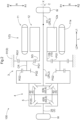
FIG. 1] FIG. 1 is a sectional view taken along an axial direction of a vehicle drive device according to an embodiment. - [
FIG. 2] FIG. 2 is a skeleton diagram of the vehicle drive device according to the embodiment. - [
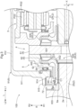
FIG. 3] FIG. 3 is a partially enlarged sectional view taken along the axial direction of the vehicle drive device according to the embodiment. - Hereinafter, a
vehicle drive device 100 according to an embodiment will be described with reference to the drawings.
As shown inFIGS. 1 and2 , thevehicle drive device 100 includes aninput member 10 drivingly connected to a driving force source D, a pair ofoutput shafts 2 drivingly connected to wheels W (seeFIG. 2 ), aspeed reducer 3 that reduces the speed of rotation of theinput member 10, and adifferential gear device 4 that distributes the rotation of theinput member 10 transmitted via thespeed reducer 3 to the pair ofoutput shafts 2. - In the following description, a direction along an output rotation axis X that is a rotation axis of the pair of
output shafts 2 will be referred to as "axial direction L." One side in the axial direction L will be referred to as "first axial side L1" and the other side in the axial direction L will be referred to as "second axial side L2." A direction orthogonal to the output rotation axis X will be referred to as "radial direction R." In the radial direction R, the side of the output rotation axis X will be referred to as "radially inner side R1" and the opposite side will be referred to as "radially outer side R2." A direction about the output rotation axis X will be referred to as "circumferential direction C." - In the present embodiment, the
input member 10, the pair ofoutput shafts 2, the speed reducer 3, and thedifferential gear device 4 are disposed coaxially. That is, theinput member 10, the pair ofoutput shafts 2, the speed reducer 3, and thedifferential gear device 4 are disposed on the output rotation axis X. In the present embodiment, theinput member 10, the speed reducer 3, and thedifferential gear device 4 are disposed in the stated order from the first axial side L1 to the second axial side L2. - In the present embodiment, the
vehicle drive device 100 further includes anouter case 9 that houses theinput member 10, the speed reducer 3, and thedifferential gear device 4. In the present embodiment, theouter case 9 includes afirst case member 91, asecond case member 92, asupport member 93, and acover member 94. - The
first case member 91 includes a firstside wall portion 911 and a firstperipheral wall portion 912. The firstside wall portion 911 is formed so as to extend along the radial direction R. The firstside wall portion 911 is disposed so as to cover thedifferential gear device 4 from the second axial side L2. The firstperipheral wall portion 912 is formed in a tubular shape having an axis along the axial direction L. The firstperipheral wall portion 912 is disposed so as to cover thespeed reducer 3 and thedifferential gear device 4 from the radially outer side R2. In the illustrated example, the firstside wall portion 911 and the firstperipheral wall portion 912 are integrally formed so that the end of the firstside wall portion 911 on the radially outer side R2 and the end of the firstperipheral wall portion 912 on the second axial side L2 are connected. That is, thefirst case member 91 is formed in a bottomed tubular shape that is open to the first axial side L1. - The
second case member 92 is structured as a separate member from thefirst case member 91. Thesecond case member 92 is joined to thefirst case member 91 from the first axial side L1. Thesecond case member 92 includes a secondperipheral wall portion 921. The secondperipheral wall portion 921 is formed in a tubular shape having an axis along the axial direction L. The secondperipheral wall portion 921 is disposed so as to cover a rotaryelectric machine 1 from the radially outer side R2. The secondperipheral wall portion 921 is joined to the firstperipheral wall portion 912 of thefirst case member 91 from the first axial side L1. - The
support member 93 is structured as a separate member from thefirst case member 91 and thesecond case member 92. Thesupport member 93 is formed so as to extend along the radial direction R. Thesupport member 93 is disposed so as to partition the inside of theouter case 9 in the axial direction L into a disposition area of the rotaryelectric machine 1 and a disposition area of thespeed reducer 3 and thedifferential gear device 4. That is, thesupport member 93 is disposed between the rotaryelectric machine 1 and thespeed reducer 3 in the axial direction L. Thesupport member 93 is fixed to thefirst case member 91. In the present embodiment, thesupport member 93 is fixed to the firstperipheral wall portion 912 so as to extend to the radially inner side R1 with respect to the firstperipheral wall portion 912. - The
cover member 94 is structured as a separate member from thefirst case member 91, thesecond case member 92, and thesupport member 93. Thecover member 94 includes a secondside wall portion 941 and a thirdperipheral wall portion 942. The secondside wall portion 941 is formed so as to extend along the radial direction R. The secondside wall portion 941 is disposed so as to cover the rotaryelectric machine 1 from the first axial side L1. The thirdperipheral wall portion 942 is formed in a tubular shape having an axis along the axial direction L. The thirdperipheral wall portion 942 is joined to the secondperipheral wall portion 921 of thesecond case member 92 from the first axial side L1. In the illustrated example, the secondside wall portion 941 and the thirdperipheral wall portion 942 are integrally formed so that the end of the secondside wall portion 941 on the radially outer side R2 and the end of the thirdperipheral wall portion 942 on the first axial side L1 are connected. That is, thecover member 94 is formed in a bottomed tubular shape that is open to the second axial side L2. - In the present embodiment, the driving force source D is the rotary
electric machine 1 including astator 11 and arotor 12. The rotaryelectric machine 1 functions as a driving force source for the pair of wheels W (seeFIG. 2 ). The rotaryelectric machine 1 has a function as a motor (electric motor) that receives supply of electric power to generate driving force, and a function as a generator (electric power generator) that receives supply of driving force to generate electric power. Specifically, the rotaryelectric machine 1 is electrically connected to a power storage device such as a battery or a capacitor (not shown). The rotaryelectric machine 1 generates a driving force by power running with electric power stored in the power storage device. The rotaryelectric machine 1 generates electric power with a driving force transmitted from the pair of wheels W to charge the power storage device. - As shown in
FIG. 1 , thestator 11 of the rotaryelectric machine 1 includes acylindrical stator core 11a. Thestator core 11a is fixed to the outer case 9 (in this case, the secondperipheral wall portion 921 of the second case member 92). Therotor 12 of the rotaryelectric machine 1 includes acylindrical rotor core 12a. Therotor core 12a is supported so as to be rotatable relative to thestator core 11a. Therotor core 12a is connected to arotor shaft 12b so as to rotate integrally with therotor shaft 12b. In the present embodiment, therotor shaft 12b corresponds to theinput member 10. - The
rotor shaft 12b is formed in a tubular shape coaxial with therotor core 12a. In the present embodiment, therotor shaft 12b is disposed so as to protrude from therotor core 12a to both sides in the axial direction L. A portion of therotor shaft 12b that protrudes from therotor core 12a to the first axial side L1 is rotatably supported on afirst support portion 943 of thecover member 94 of theouter case 9 via a first bearing B1. In the example shown inFIG. 1 , thefirst support portion 943 is formed in a tubular shape that protrudes from the secondside wall portion 941 to the second axial side L2 and covers therotor shaft 12b from the radially outer side R2. The first bearing B1 is disposed between thefirst support portion 943 and therotor shaft 12b in the radial direction R. In the present embodiment, a portion of therotor shaft 12b that protrudes from therotor core 12a to the second axial side L2 is disposed so as to extend through thesupport member 93 of theouter case 9 in the axial direction L. The portion of therotor shaft 12b that protrudes from therotor core 12a to the second axial side L2 is supported so as to be rotatable relative to thesupport member 93 via a second bearing B2. - In the present embodiment, the rotary
electric machine 1 is an inner rotor type rotary electric machine. Therefore, therotor core 12a is disposed on the radially inner side R1 of thestator core 11a. Therotor shaft 12b is disposed on the radially inner side R1 of therotor core 12a. - In the present embodiment, the rotary
electric machine 1 is a revolving field type rotary electric machine. Therefore, thestator 11 further includes astator coil 11b. In the present embodiment, thestator coil 11b is wound around thestator core 11a so as to form coil end portions protruding from thestator core 11a to both sides in the axial direction L. Although illustration is omitted, therotor core 12a is provided with permanent magnets. - In the present embodiment, the
speed reducer 3 is a planetary gear mechanism including a sun gear SG, a carrier CR, a first ring gear RG1, and a second ring gear RG2. - In the present embodiment, the sun gear SG is connected to the
rotor 12 so as to rotate integrally with therotor 12. In the example shown inFIG. 1 , the sun gear SG is connected to therotor shaft 12b by welding etc. so as to rotate integrally with therotor shaft 12b. - In the present embodiment, the carrier CR rotatably supports first pinion gears PG1 and second pinion gears PG2. The first pinion gears PG1 and the second pinion gears PG2 are connected so as to rotate integrally with each other. The first pinion gears PG1 mesh with the sun gear SG and the first ring gear RG1. The second pinion gears PG2 mesh with the second ring gear RG2. The second pinion gear PG2 has a smaller diameter than the first pinion gear PG1.
- In the present embodiment, the first ring gear RG1 is fixed to the
outer case 9. In the example shown inFIG. 1 , the first ring gear RG1 is fixed to thesupport member 93 of theouter case 9. - The
differential gear device 4 includes adifferential case 5 and adifferential gear mechanism 6 housed in thedifferential case 5. Thedifferential gear device 4 is a bevel gear type differential gear device. - The
differential case 5 rotates about the output rotation axis X. Thedifferential case 5 is an input element of thedifferential gear device 4. In the present embodiment, thedifferential case 5 is connected to the second ring gear RG2 of thespeed reducer 3 by welding etc. so as to rotate integrally with the second ring gear RG2. - The
differential gear mechanism 6 includesshaft members 61, a plurality offirst bevel gears 62, and a pair of second bevel gears 63. - The
shaft members 61 are supported by thedifferential case 5 so as to rotate integrally with thedifferential case 5. Theshaft members 61 are formed so as to extend along the radial direction R. In the present embodiment, theshaft members 61 are radially formed along the radial direction R (e.g., formed in a cross shape in an axial view along the axial direction L). - The plurality of first bevel gears 62 is disposed separately in the circumferential direction C. The plurality of first bevel gears 62 is rotatably supported by the
shaft members 61. More specifically, each of the plurality of first bevel gears 62 is rotatable (spinnable) about its own axis and rotatable (revolvable) about the output rotation axis X. In this example, fourfirst bevel gears 62 are provided. - The pair of second bevel gears 63 is disposed separately on both sides of the
shaft members 61 in the axial direction L. The pair of second bevel gears 63 meshes with the plurality of first bevel gears 62. The pair of second bevel gears 63 rotates about the output rotation axis X. The pair of second bevel gears 63 is connected to the pair ofoutput shafts 2 so as to rotate integrally with the pair ofoutput shafts 2. - In the following description, one of the pair of second bevel gears 63 that is disposed on the second axial side L2 with respect to the
shaft members 61 will be referred to as "specific bevel gear 63S." One of the pair of second bevel gears 63 that is disposed on the first axial side L1 with respect to theshaft members 61 will be referred to as "non-specific bevel gear 63N." One of the pair ofoutput shafts 2 that rotates integrally with the specific bevel gear 63S will be referred to as "specific output shaft 2S." One of the pair ofoutput shafts 2 that rotates integrally with thenon-specific bevel gear 63N will be referred to as "non-specific output shaft 2N." - In the present embodiment, the
specific output shaft 2S is a drive shaft. Thenon-specific output shaft 2N includes atransmission shaft 21 and adrive shaft 22. - The
transmission shaft 21 is connected to thenon-specific bevel gear 63N so as to rotate integrally with thenon-specific bevel gear 63N. In the example shown inFIG. 1 , thetransmission shaft 21 is inserted from the first axial side L1 to the radially inner side R1 of thenon-specific bevel gear 63N and is connected to thenon-specific bevel gear 63N by spline engagement. - The
transmission shaft 21 is connected to thedrive shaft 22 so as to rotate integrally with thedrive shaft 22. In the present embodiment, thetransmission shaft 21 includes aconnection portion 211 connected to thedrive shaft 22. Theconnection portion 211 is disposed at an end of thetransmission shaft 21 on the first axial side L1. Theconnection portion 211 is formed in a tubular shape that is open to the first axial side L1. In the example shown inFIG. 1 , thedrive shaft 22 is inserted from the first axial side L1 to the radially inner side R1 of theconnection portion 211 and they are connected to each other by spline engagement. - In the present embodiment, the
connection portion 211 is rotatably supported on asecond support portion 944 of thecover member 94 of theouter case 9 via a third bearing B3. In the example shown inFIG. 1 , thesecond support portion 944 is formed in a tubular shape that protrudes from the secondside wall portion 941 to the first axial side L1 and covers theconnection portion 211 from the radially outer side R2. The third bearing B3 is disposed between thesecond support portion 944 and theconnection portion 211 in the radial direction R. - In the present embodiment, a
first seal member 71 is provided between theconnection portion 211 and thesecond support portion 944 in the radial direction R. Thefirst seal member 71 is disposed so as to provide an oil-tight seal between the outer peripheral surface of theconnection portion 211 and the inner peripheral surface of thesecond support portion 944. - As shown in
FIG. 3 , in the present embodiment, the specific bevel gear 63S includes abevel tooth portion 631, a beveltooth support portion 632, and atubular shaft portion 633. - The
bevel tooth portion 631 is formed so as to mesh with the plurality of first bevel gears 62. Thebevel tooth portion 631 is composed of a plurality of teeth disposed at equal intervals in the circumferential direction C. - The bevel
tooth support portion 632 supports thebevel tooth portion 631. The beveltooth support portion 632 is formed integrally with thebevel tooth portion 631. More specifically, the beveltooth support portion 632 has a surface in the shape of a side surface of a truncated cone oriented to the first axial side L1 and the radially outer side R2, and thebevel tooth portion 631 is formed on this surface. In the present embodiment, the beveltooth support portion 632 is supported so as to be rotatable relative to thedifferential case 5 via a washer WS disposed between a surface of the beveltooth support portion 632 that is oriented to the second axial side L2 and a portion of the inner surface of thedifferential case 5 that is oriented to the first axial side L1. In this way, the specific bevel gear 63S is supported on thedifferential case 5 in the axial direction L. - The
tubular shaft portion 633 is formed in a tubular shape extending from the beveltooth support portion 632 to the second axial side L2. In the example shown inFIG. 3 , thetubular shaft portion 633 is formed integrally with the beveltooth support portion 632. - In the present embodiment, the
differential case 5 includes a differential casetubular portion 51. The differential casetubular portion 51 is formed in a tubular shape. The differential casetubular portion 51 is disposed so as to cover thetubular shaft portion 633 of the specific bevel gear 63S from the radially outer side R2. A first clearance C1 that is a clearance in the radial direction R is provided between the outer peripheral surface of thetubular shaft portion 633 and the inner peripheral surface of the differential casetubular portion 51. In this way, the specific bevel gear 63S is not supported on thedifferential case 5 in the radial direction R. The specific bevel gear 63S is supported in the radial direction R by an aligning action caused by meshing with the plurality of first bevel gears 62. - The
specific output shaft 2S includes an engagingportion 2a. The specific bevel gear 63S includes an engagedportion 6a with which the engagingportion 2a engages. The engagingportion 2a and the engagedportion 6a engage with each other so as to restrict relative movement in the circumferential direction C and the radial direction R between thespecific output shaft 2S and the specific bevel gear 63S. In the present embodiment, a portion of thespecific output shaft 2S on the second axial side L2 with respect to the portion where the engagingportion 2a is formed is positioned away from the specific bevel gear 63 S (specifically, the tubular shaft portion 633). In the present embodiment, thespecific output shaft 2S is disposed away from thedifferential case 5. In the example shown inFIG. 3 , a portion of thespecific output shaft 2S that faces the differential casetubular portion 51 in the radial direction R is covered from the radially outer side R2 by thetubular shaft portion 633 that is disposed with the clearance in the radial direction R from the differential casetubular portion 51. - In the present embodiment, each of the engaging
portion 2a and the engagedportion 6a is composed of a plurality of spline teeth distributed in the circumferential direction C. In the present embodiment, thespecific output shaft 2S is inserted from the second axial side L2 to the radially inner side R1 of thetubular shaft portion 633 of the specific bevel gear 63S. The engagingportion 2a is formed on the outer peripheral surface of the portion of thespecific output shaft 2S that is inserted to thetubular shaft portion 633, and the engagedportion 6a is formed on the inner peripheral surface of thetubular shaft portion 633. - As described above, the vehicle drive device 100 is the vehicle drive device 100 including: the input member 10 drivingly connected to the driving force source D; the pair of output shafts 2 drivingly connected to the wheels W; the speed reducer 3 configured to reduce the speed of rotation of the input member 10; and the differential gear device 4 configured to distribute the rotation of the input member 10 transmitted via the speed reducer 3 to the pair of output shafts 2, in which the differential gear device 4 includes the differential case 5 and the differential gear mechanism 6 housed in the differential case 5, the differential gear mechanism 6 includes the shaft members 61 formed so as to extend along the radial direction R, the plurality of first bevel gears 62 rotatably supported by the shaft members 61 and disposed separately in the circumferential direction C, and the pair of second bevel gears 63 disposed separately on both sides of the shaft members 61 in the axial direction L and meshing with the plurality of first bevel gears 62, the pair of second bevel gears 63 is connected to the pair of output shafts 2 so as to rotate integrally with the pair of output shafts 2, and assuming that one of the pair of second bevel gears 63 that is disposed on the second axial side L2 with respect to the shaft members 61 is the specific bevel gear 63S and one of the pair of output shafts 2 that rotates integrally with the specific bevel gear 63S is the specific output shaft 2S, the engaging portion 2a provided on the specific output shaft 2S and the engaged portion 6a provided on the specific bevel gear 63S engage with each other so as to restrict relative movement in the circumferential direction C and the radial direction R between the specific output shaft 2S and the specific bevel gear 63 S, and the specific bevel gear 63S is supported on the differential case 5 in the axial direction L and is not supported on the differential case 5 in the radial direction R.
- In this configuration, the specific bevel gear 63S is not supported on the
differential case 5 in the radial direction R, and is supported in the radial direction R by the aligning action caused by the meshing between the specific bevel gear 63 S and the plurality of first bevel gears 62. Therefore, there is no need to provide a bearing or a fitting portion for supporting the specific bevel gear 63 S on thedifferential case 5 in the radial direction R. In this configuration, the engagingportion 2a of thespecific output shaft 2S and the engagedportion 6a of the specific bevel gear 63S restrict the relative movement in the circumferential direction C and the radial direction R. Therefore, there is no need to provide the specific bevel gear 63S with a fitting portion to which thespecific output shaft 2S is fitted and that restricts misalignment or inclination between the rotation axis of thespecific output shaft 2S and the rotation axis of the specific bevel gear 63S.
As described above, with this configuration, the support structure for supporting the specific bevel gear 63S and thespecific output shaft 2S on thedifferential case 5 can be downsized easily. Therefore, thevehicle drive device 100 can easily be downsized in the configuration including the bevel gear typedifferential gear device 4. - As described above, in the present embodiment, the specific bevel gear 63 S includes the
bevel tooth portion 631 that meshes with the plurality offirst bevel gears 62, the beveltooth support portion 632 that is formed integrally with thebevel tooth portion 631 and supports thebevel tooth portion 631, and thetubular shaft portion 633 that is formed in the tubular shape extending from the beveltooth support portion 632 to the second axial side L2, thedifferential case 5 includes the differential casetubular portion 51 that is formed in the tubular shape and is disposed so as to cover thetubular shaft portion 633 from the radially outer side R2, and the first clearance C1 that is the clearance in the radial direction R is provided between the outer peripheral surface of thetubular shaft portion 633 and the inner peripheral surface of the differential casetubular portion 51. - With this configuration, it is possible to appropriately realize the configuration in which the specific bevel gear 63S is not supported on the
differential case 5 in the radial direction R. Therefore, it is possible to appropriately realize the configuration in which the specific bevel gear 63S is supported in the radial direction R by the aligning action caused by the meshing between the specific bevel gear 63 S and the first bevel gears 62. - As shown in
FIG. 3 , in the present embodiment, a second clearance C2 that is a clearance in the radial direction R is provided between a tooth surface of each of the plurality offirst bevel gears 62 and a tooth surface of the specific bevel gear 63S. The first clearance C1 is larger than the second clearance C2. The tooth surface of thefirst bevel gear 62 is a surface of each of the projections and recesses defining the teeth of thefirst bevel gear 62 and is a surface oriented outward in a direction orthogonal to the spinning axis of thefirst bevel gear 62. The tooth surface of the specific bevel gear 63S is a surface of each of the projections and recesses defining the teeth of the specific bevel gear 63S and is a surface oriented to one side in the axial direction L (in this case, the first axial side L1). The second clearance C2 is a distance in the radial direction R at the portion where the tooth surface of each of the plurality offirst bevel gears 62 and the tooth surface of the specific bevel gear 63S face each other in the radial direction R. In the illustrated example, part of the tip surface of thefirst bevel gear 62 and part of the root surface of the specific bevel gear 63S are disposed so as to face each other in the radial direction R. More specifically, the tip surface of thefirst bevel gear 62 and the root surface of the specific bevel gear 63S each have an inclined portion that is gradually inclined to the first axial side L1 as it is closer to the radially inner side R1. The second clearance C2 is provided between the inclined portions in the radial direction R. - In this configuration, when the
specific output shaft 2S is not rotating and thefirst bevel gear 62 moves to the radially inner side R1 relative to the specific bevel gear 63S so that the differential casetubular portion 51 approaches thetubular shaft portion 633, the second clearance C2 becomes zero before the first clearance C1 becomes zero. Therefore, further movement of thefirst bevel gear 62 to the radially inner side R1 relative to the specific bevel gear 63S can be restricted. Thus, the contact of the differential casetubular portion 51 with thetubular shaft portion 633 can be avoided. - As shown in
FIG. 3 , in the present embodiment, theouter case 9 further includes anouter support portion 914. Theouter support portion 914 is disposed on the radially outer side R2 with respect to the differential casetubular portion 51. In the example shown inFIG. 3 , theouter support portion 914 is formed so as to protrude to the radially inner side R1 from an end of the firstside wall portion 911 of thefirst case member 91 on the radially inner side R1. Theouter support portion 914 is formed in an annular shape with the output rotation axis X as its axis. - In the present embodiment, the
differential case 5 further includes aradial extension portion 52. Theradial extension portion 52 is formed so as to extend along the radial direction R. Theradial extension portion 52 is disposed on the first axial side L1 with respect to theouter support portion 914. A thrust bearing B4 that supports theradial extension portion 52 in the axial direction L is provided between a surface of theradial extension portion 52 that is oriented to the second axial side L2 and a surface of theouter support portion 914 that is oriented to the first axial side L1. In the example shown inFIG. 3 , the thrust bearing B4 is a needle roller bearing. In the present embodiment, the above washer WS is provided between a surface of theradial extension portion 52 that is oriented to the first axial side L1 and a surface of the beveltooth support portion 632 of the specific bevel gear 63 S that is oriented to the second axial side L2. - In the present embodiment, a radial bearing B5 that supports the differential case
tubular portion 51 in the radial direction R is provided between the outer peripheral surface of the differential casetubular portion 51 and the inner peripheral surface of theouter support portion 914. In the example shown inFIG. 3 , the radial bearing B5 is a bushing. - As described above, in the present embodiment, the
outer case 9 that houses theinput member 10, thespeed reducer 3, and thedifferential gear device 4 is further provided, theouter case 9 includes theouter support portion 914 disposed on the radially outer side R2 with respect to the differential casetubular portion 51, thedifferential case 5 further includes theradial extension portion 52 formed so as to extend along the radial direction R and disposed on the first axial side L1 with respect to theouter support portion 914, the thrust bearing B4 that supports theradial extension portion 52 in the axial direction L is provided between the surface of theradial extension portion 52 that is oriented to the second axial side L2 and the surface of theouter support portion 914 that is oriented to the first axial side L1, and the radial bearing B5 that supports the differential casetubular portion 51 in the radial direction R is provided between the outer peripheral surface of the differential casetubular portion 51 and the inner peripheral surface of theouter support portion 914. - In this configuration, the bearings that support the
differential case 5 on theouter case 9 are divided into the thrust bearing B4 that supports thedifferential case 5 in the axial direction L and the radial bearing B5 that supports thedifferential case 5 in the radial direction R. Therefore, the radial bearing B5 can be downsized easily. Thus, the structures of thedifferential case 5 and theouter case 9 around the radial bearing B5 can also be downsized easily. - In the present embodiment, the
outer case 9 further includes an outer casetubular portion 915. The outer casetubular portion 915 is formed in a tubular shape. The outer casetubular portion 915 is disposed so as to cover thetubular shaft portion 633 from the radially outer side R2. In the present embodiment, the outer casetubular portion 915 is formed so as to protrude to the second axial side L2 from the end of the firstside wall portion 911 of thefirst case member 91 on the radially inner side R1. - In the present embodiment, a
second seal member 72 is provided to provide an oil-tight seal between the outer peripheral surface of thetubular shaft portion 633 and the inner peripheral surface of the outer casetubular portion 915. In the example shown inFIG. 3 , thetubular shaft portion 633 has a protruding portion that protrudes to the second axial side L2 with respect to the differential casetubular portion 51, and thesecond seal member 72 is disposed between the outer peripheral surface of the protruding portion of thetubular shaft portion 633 and the inner peripheral surface of the outer casetubular portion 915. Thesecond seal member 72 is disposed so as to overlap the engagedportion 6a of the specific bevel gear 63S in a radial view along the radial direction R. Regarding the disposition of two elements, the phrase "overlap when viewed in a specific direction" means that, when a virtual straight line parallel to the line-of-sight direction is moved in directions orthogonal to the virtual straight line, an area where the virtual straight line intersects both the two elements is present at least in part. - As described above, in the present embodiment, the
outer case 9 that houses theinput member 10, thespeed reducer 3, and thedifferential gear device 4 is further provided, theouter case 9 further includes the outer casetubular portion 915 that is formed in the tubular shape and is disposed so as to cover thetubular shaft portion 633 from the radially outer side R2, thesecond seal member 72 is provided to provide the oil-tight seal between the outer peripheral surface of thetubular shaft portion 633 and the inner peripheral surface of the outer casetubular portion 915, and thesecond seal member 72 is disposed so as to overlap the engagedportion 6a in the radial view along the radial direction R. - This configuration can be realized because, as described above, the specific bevel gear 63S is not provided with a fitting portion that restricts misalignment or inclination between the rotation axis of the
specific output shaft 2S and the rotation axis of the specific bevel gear 63S. With this configuration, it is possible to appropriately restrict leakage of oil inside theouter case 9 through the gap in the radial direction R between the outer peripheral surface of thetubular shaft portion 633 and the inner peripheral surface of the outer casetubular portion 915 while reducing the dimension of thevehicle drive device 100 in the axial direction L, compared to a configuration in which thesecond seal member 72 is offset in the axial direction L from the engagedportion 6a. - In the present embodiment, the
outer case 9 that houses theinput member 10, thespeed reducer 3, and thedifferential gear device 4 is further provided, theouter case 9 includes theouter support portion 914 disposed on the radially outer side R2 with respect to the differential casetubular portion 51, and theouter support portion 914, the differential casetubular portion 51, and the engagedportion 6a are disposed so as to overlap each other in the radial view along the radial direction R. - With this configuration, the dimension of the
vehicle drive device 100 in the axial direction L can easily be reduced compared to a configuration in which theouter support portion 914, the differential casetubular portion 51, and the engagedportion 6a are offset in the axial direction L. -
- (1) The above embodiment illustrates the exemplary configuration in which the driving force source D drivingly connected to the
input member 10 is the rotaryelectric machine 1. However, the present invention is not limited to such a configuration, and the driving force source D may be an internal combustion engine. In this case, the rotaryelectric machine 1 may be omitted and the wheels W may be driven using only the driving force of the internal combustion engine. Alternatively, the wheels W may be driven using the driving forces of both the internal combustion engine and the rotary electric machine, that is, thevehicle drive device 100 may be a drive device for a hybrid vehicle. - (2) The above embodiment illustrates the exemplary configuration in which the
input member 10, the pair ofoutput shafts 2, thespeed reducer 3, and thedifferential gear device 4 are disposed coaxially and theinput member 10, thespeed reducer 3, and thedifferential gear device 4 are disposed in the stated order from the first axial side L1 to the second axial side L2. However, the present invention is not limited to such a configuration, and at least one of theinput member 10, the pair ofoutput shafts 2, thespeed reducer 3, and thedifferential gear device 4 may be disposed on a different axis. The disposition order of theinput member 10, thespeed reducer 3, and thedifferential gear device 4 in the axial direction L may be different from the above order. - (3) The above embodiment illustrates the exemplary configuration in which the
speed reducer 3 is the planetary gear mechanism disposed on the output rotation axis X. However, the present invention is not limited to such a configuration. For example, thespeed reducer 3 may be a counter gear mechanism instead of the planetary gear mechanism. In this configuration, the counter gear mechanism is disposed on the output rotation axis X and on an axis different from the output rotation axis X. - (4) The above embodiment illustrates the exemplary configuration in which the
speed reducer 3 is the planetary gear mechanism including the sun gear SG, the carrier CR, the first ring gear RG1, and the second ring gear RG2. However, the present invention is not limited to such a configuration, and thespeed reducer 3 may be, for example, a single-pinion type planetary gear mechanism. - (5) The above embodiment illustrates the exemplary configuration in which the thrust bearing B4 that supports the
radial extension portion 52 in the axial direction L is provided between the surface of theradial extension portion 52 that is oriented to the second axial side L2 and the surface of theouter support portion 914 that is oriented to the first axial side L1, and the radial bearing B5 that supports the differential casetubular portion 51 in the radial direction R is provided between the outer peripheral surface of the differential casetubular portion 51 and the inner peripheral surface of theouter support portion 914. However, the present invention is not limited to such a configuration. For example, ball bearings that support thedifferential case 5 in the axial direction L and the radial direction R may be provided between the surface of thedifferential case 5 that is oriented to the second axial side L2 and the surface of theouter support portion 914 that is oriented to the first axial side L1 and between the outer peripheral surface of thedifferential case 5 and the inner peripheral surface of theouter support portion 914. - (6) The above embodiment illustrates the exemplary configuration in which the
second seal member 72 is disposed so as to overlap the engagedportion 6a in the radial view along the radial direction R. However, the present invention is not limited to such a configuration. For example, thesecond seal member 72 may be disposed on the second axial side L2 with respect to the engagedportion 6a. - (7) The above embodiment illustrates the exemplary configuration in which the
outer support portion 914, the differential casetubular portion 51, and the engagedportion 6a are disposed so as to overlap each other in the radial view along the radial direction R. However, the present invention is not limited to such a configuration. For example, the engagedportion 6a may be disposed on the second axial side L2 with respect to theouter support portion 914 and the differential casetubular portion 51. - (8) The configuration disclosed in each of the above embodiments can be applied in combination with any of the configurations disclosed in the other embodiments as long as no contradiction arises. Regarding the other configurations as well, the embodiments disclosed herein are merely illustrative in all respects. Therefore, various modifications can be made as appropriate without departing from the spirit of the present disclosure.
- Hereinafter, a summary of the vehicle drive device (100) described above will be provided.
- The vehicle drive device (100) is a vehicle drive device (100) including: an input member (10) drivingly connected to a driving force source (D); a pair of output shafts (2) drivingly connected to wheels (W); a speed reducer (3) configured to reduce a speed of rotation of the input member (10); and a differential gear device (4) configured to distribute the rotation of the input member (10) transmitted via the speed reducer (3) to the pair of output shafts (2), in which, assuming that an axial direction (L) is a direction along an output rotation axis (X) that is a rotation axis of the pair of output shafts (2), a first axial side (L1) is one side in the axial direction (L), a second axial side (L2) is the other side in the axial direction (L), a radial direction (R) is a direction orthogonal to the output rotation axis (X), and a circumferential direction (C) is a direction about the output rotation axis (X), the differential gear device (4) includes a differential case (5) and a differential gear mechanism (6) housed in the differential case (5), the differential gear mechanism (6) includes a shaft member (61) formed so as to extend along the radial direction (R), a plurality of first bevel gears (62) rotatably supported by the shaft member (61) and disposed separately in the circumferential direction (C), and a pair of second bevel gears (63) disposed separately on both sides of the shaft member (61) in the axial direction (L) and meshing with the plurality of first bevel gears (62), the pair of second bevel gears (63) is connected to the pair of output shafts (2) so as to rotate integrally with the pair of output shafts (2), and assuming that one of the pair of second bevel gears (63) that is disposed on the second axial side (L2) with respect to the shaft member (61) is a specific bevel gear (63 S) and one of the pair of output shafts (2) that rotates integrally with the specific bevel gear (63 S) is a specific output shaft (2S), an engaging portion (2a) provided on the specific output shaft (2S) and an engaged portion (6a) provided on the specific bevel gear (63S) engage with each other so as to restrict relative movement in the circumferential direction (C) and the radial direction (R) between the specific output shaft (2S) and the specific bevel gear (63S), and the specific bevel gear (63S) is supported on the differential case (5) in the axial direction (L) and is not supported on the differential case (5) in the radial direction (R).
- In this configuration, the specific bevel gear (63 S) is not supported on the differential case (5) in the radial direction (R), and is supported in the radial direction (R) by an aligning action caused by meshing between the specific bevel gear (63 S) and the plurality of first bevel gears (62). Therefore, there is no need to provide a bearing or a fitting portion for supporting the specific bevel gear (63 S) on the differential case (5) in the radial direction (R).
In this configuration, the engaging portion (2a) of the specific output shaft (2S) and the engaged portion (6a) of the specific bevel gear (63 S) restrict the relative movement in the circumferential direction (C) and the radial direction (R). Therefore, there is no need to provide the specific bevel gear (63 S) with a fitting portion to which the specific output shaft (2S) is fitted and that restricts misalignment or inclination between the rotation axis of the specific output shaft (2S) and the rotation axis of the specific bevel gear (63S).
As described above, with this configuration, the support structure for supporting the specific bevel gear (63 S) and the specific output shaft (2S) on the differential case (5) can be downsized easily. Therefore, the vehicle drive device (100) can easily be downsized in the configuration including the bevel gear type differential gear device (4). - It is preferable that the specific bevel gear (63 S) include a bevel tooth portion (631) that meshes with the plurality of first bevel gears (62), a bevel tooth support portion (632) that is formed integrally with the bevel tooth portion (631) and supports the bevel tooth portion (631), and a tubular shaft portion (633) that is formed in a tubular shape extending from the bevel tooth support portion (632) to the second axial side (L2), the differential case (5) include a differential case tubular portion (51) that is formed in a tubular shape and is disposed so as to cover the tubular shaft portion (633) from an outer side (R2) in the radial direction (R), and a first clearance (C 1) that is a clearance in the radial direction (R) be provided between an outer peripheral surface of the tubular shaft portion (633) and an inner peripheral surface of the differential case tubular portion (51).
- With this configuration, it is possible to appropriately realize the configuration in which the specific bevel gear (63S) is not supported on the differential case (5) in the radial direction (R). Therefore, it is possible to appropriately realize the configuration in which the specific bevel gear (63 S) is supported in the radial direction (R) by the aligning action caused by the meshing between the specific bevel gear (63 S) and the first bevel gears (62).
- In the configuration in which the first clearance (C1) is provided between the outer peripheral surface of the tubular shaft portion (633) and the inner peripheral surface of the differential case tubular portion (51), it is preferable that a second clearance (C2) that is a clearance in the radial direction (R) be provided between a tooth surface of each of the plurality of first bevel gears (62) and a tooth surface of the specific bevel gear (63 S), and the first clearance (C1) be larger than the second clearance (C2).
- In this configuration, when the specific output shaft (2S) is not rotating and the first bevel gear (62) moves to an inner side (R1) in the radial direction (R) relative to the specific bevel gear (63 S) so that the differential case tubular portion (51) approaches the tubular shaft portion (633), the second clearance (C2) becomes zero before the first clearance (C1) becomes zero. Therefore, further movement of the first bevel gear (62) to the inner side (R1) in the radial direction (R) relative to the specific bevel gear (63 S) can be restricted. Thus, the contact of the differential case tubular portion (51) with the tubular shaft portion (633) can be avoided.
- It is preferable that the vehicle drive device (100) further include an outer case (9) that houses the input member (10), the speed reducer (3), and the differential gear device (4), the outer case (9) further include an outer case tubular portion (915) that is formed in a tubular shape and is disposed so as to cover the tubular shaft portion (633) from the outer side (R2) in the radial direction (R), a seal member (72) be provided to provide an oil-tight seal between the outer peripheral surface of the tubular shaft portion (633) and an inner peripheral surface of the outer case tubular portion (915), and the seal member (72) be disposed so as to overlap the engaged portion (6a) in a radial view along the radial direction (R).
- This configuration can be realized because, as described above, the specific bevel gear (63 S) is not provided with a fitting portion that restricts misalignment or inclination between the rotation axis of the specific output shaft (2S) and the rotation axis of the specific bevel gear (63 S). With this configuration, it is possible to appropriately restrict leakage of oil inside the outer case (9) through a gap in the radial direction (R) between the outer peripheral surface of the tubular shaft portion (633) and the inner peripheral surface of the outer case tubular portion (915) while reducing the dimension of the vehicle drive device (100) in the axial direction (L), compared to a configuration in which the second seal member (72) is offset in the axial direction (L) from the engaged portion (6a).
- It is preferable that the vehicle drive device (100) further include an outer case (9) that houses the input member (10), the speed reducer (3), and the differential gear device (4), the outer case (9) include an outer support portion (914) disposed on the outer side (R2) in the radial direction (R) with respect to the differential case tubular portion (51), and the outer support portion (914), the differential case tubular portion (51), and the engaged portion (6a) be disposed so as to overlap each other in a radial view along the radial direction (R).
- With this configuration, the dimension of the vehicle drive device (100) in the axial direction (L) can easily be reduced compared to a configuration in which the outer support portion (914), the differential case tubular portion (51), and the engaged portion (6a) are offset in the axial direction (L).
- The technology disclosed herein is applicable to a vehicle drive device including an input member drivingly connected to a driving force source, a pair of output shafts drivingly connected to wheels, a speed reducer that reduces the speed of rotation of the input member, and a differential gear device that distributes the rotation of the input member transmitted via the speed reducer to the pair of output shafts.
- 100: vehicle drive device, 10: input member, 2: output shaft, 2S: specific output shaft, 2a: engaging portion, 3: speed reducer, 4: differential gear device, 5: differential case, 51: differential case tubular portion, 52: radial extension portion, 6: differential gear mechanism, 6a: engaged portion, 61: shaft member, 62: first bevel gear, 63: second bevel gear, 63S: specific bevel gear, 631: bevel tooth portion, 632: bevel tooth support portion, 633: tubular shaft portion, 72: second seal member (seal member), 9: outer case, 914: outer support portion, 915: outer case tubular portion, D: driving force source, B4: thrust bearing, B5: radial bearing, W: wheel, L: axial direction, L1: first axial side, L2: second axial side, R: radial direction, R1: radially inner side, R2: radially outer side, C: circumferential direction
Claims (5)
- A vehicle drive device comprising:an input member drivingly connected to a driving force source;a pair of output shafts drivingly connected to wheels;a speed reducer configured to reduce a speed of rotation of the input member; anda differential gear device configured to distribute the rotation of the input member transmitted via the speed reducer to the pair of output shafts, whereinassuming that an axial direction is a direction along an output rotation axis that is a rotation axis of the pair of output shafts, a first axial side is one side in the axial direction, a second axial side is the other side in the axial direction, a radial direction is a direction orthogonal to the output rotation axis, and a circumferential direction is a direction about the output rotation axis,the differential gear device includes a differential case and a differential gear mechanism housed in the differential case,the differential gear mechanism includes a shaft member formed so as to extend along the radial direction, a plurality of first bevel gears rotatably supported by the shaft member and disposed separately in the circumferential direction, and a pair of second bevel gears disposed separately on both sides of the shaft member in the axial direction and meshing with the plurality of first bevel gears,the pair of second bevel gears is connected to the pair of output shafts so as to rotate integrally with the pair of output shafts, andassuming that one of the pair of second bevel gears that is disposed on the second axial side with respect to the shaft member is a specific bevel gear and one of the pair of output shafts that rotates integrally with the specific bevel gear is a specific output shaft,an engaging portion provided on the specific output shaft and an engaged portion provided on the specific bevel gear engage with each other so as to restrict relative movement in the circumferential direction and the radial direction between the specific output shaft and the specific bevel gear, andthe specific bevel gear is supported on the differential case in the axial direction and is not supported on the differential case in the radial direction.
- The vehicle drive device according to claim 1, wherein:the specific bevel gear includes a bevel tooth portion that meshes with the plurality of first bevel gears, a bevel tooth support portion that is formed integrally with the bevel tooth portion and supports the bevel tooth portion, and a tubular shaft portion that is formed in a tubular shape extending from the bevel tooth support portion to the second axial side;the differential case includes a differential case tubular portion that is formed in a tubular shape and is disposed so as to cover the tubular shaft portion from an outer side in the radial direction; anda first clearance that is a clearance in the radial direction is provided between an outer peripheral surface of the tubular shaft portion and an inner peripheral surface of the differential case tubular portion.
- The vehicle drive device according to claim 2, wherein:a second clearance that is a clearance in the radial direction is provided between a tooth surface of each of the plurality of first bevel gears and a tooth surface of the specific bevel gear; andthe first clearance is larger than the second clearance.
- The vehicle drive device according to claim 2 or 3, further comprising an outer case that houses the input member, the speed reducer, and the differential gear device, whereinthe outer case further includes an outer case tubular portion that is formed in a tubular shape and is disposed so as to cover the tubular shaft portion from the outer side in the radial direction,a seal member is provided to provide an oil-tight seal between the outer peripheral surface of the tubular shaft portion and an inner peripheral surface of the outer case tubular portion, andthe seal member is disposed so as to overlap the engaged portion in a radial view along the radial direction.
- The vehicle drive device according to claim 2 or 3, further comprising an outer case that houses the input member, the speed reducer, and the differential gear device, whereinthe outer case includes an outer support portion disposed on the outer side in the radial direction with respect to the differential case tubular portion, andthe outer support portion, the differential case tubular portion, and the engaged portion are disposed so as to overlap each other in a radial view along the radial direction.
Applications Claiming Priority (2)
| Application Number | Priority Date | Filing Date | Title |
|---|---|---|---|
| JP2022128806 | 2022-08-12 | ||
| PCT/JP2023/028267 WO2024034489A1 (en) | 2022-08-12 | 2023-08-02 | Vehicular drive device |
Publications (2)
| Publication Number | Publication Date |
|---|---|
| EP4502425A1 true EP4502425A1 (en) | 2025-02-05 |
| EP4502425A4 EP4502425A4 (en) | 2025-09-03 |
Family
ID=89851577
Family Applications (1)
| Application Number | Title | Priority Date | Filing Date |
|---|---|---|---|
| EP23852456.5A Pending EP4502425A4 (en) | 2022-08-12 | 2023-08-02 | VEHICLE DRIVE DEVICE |
Country Status (4)
| Country | Link |
|---|---|
| EP (1) | EP4502425A4 (en) |
| JP (1) | JP7711849B2 (en) |
| CN (1) | CN119404028A (en) |
| WO (1) | WO2024034489A1 (en) |
Family Cites Families (5)
| Publication number | Priority date | Publication date | Assignee | Title |
|---|---|---|---|---|
| JPH10213209A (en) * | 1997-01-30 | 1998-08-11 | Aisin Aw Co Ltd | Automatic transmission |
| JP4778648B2 (en) * | 2001-09-14 | 2011-09-21 | Gknドライブラインジャパン株式会社 | Power transmission device for electric motor and method of assembling the same |
| EP3663609B1 (en) * | 2017-10-13 | 2023-08-30 | Aisin Corporation | Drive device for vehicle |
| JP7573932B2 (en) | 2019-12-30 | 2024-10-28 | ジヤトコ株式会社 | Power transmission |
| EP4428399A4 (en) * | 2022-03-25 | 2025-04-23 | Aisin Corporation | VEHICLE DRIVE DEVICE |
-
2023
- 2023-08-02 EP EP23852456.5A patent/EP4502425A4/en active Pending
- 2023-08-02 JP JP2024540417A patent/JP7711849B2/en active Active
- 2023-08-02 CN CN202380049078.XA patent/CN119404028A/en active Pending
- 2023-08-02 WO PCT/JP2023/028267 patent/WO2024034489A1/en not_active Ceased
Also Published As
| Publication number | Publication date |
|---|---|
| WO2024034489A1 (en) | 2024-02-15 |
| JP7711849B2 (en) | 2025-07-23 |
| CN119404028A (en) | 2025-02-07 |
| EP4502425A4 (en) | 2025-09-03 |
| JPWO2024034489A1 (en) | 2024-02-15 |
Similar Documents
| Publication | Publication Date | Title |
|---|---|---|
| JP4873264B2 (en) | Drive device | |
| EP2507532B1 (en) | Hybrid drive system | |
| EP3663614B1 (en) | Vehicle drive device | |
| US20250018788A1 (en) | Drive device for vehicle | |
| US11802614B2 (en) | Vehicle drive device | |
| US12338884B2 (en) | Vehicle drive device | |
| JP2009286367A (en) | Hybrid drive unit | |
| US20240392865A1 (en) | Vehicle drive device | |
| JP5093601B2 (en) | Hybrid drive unit | |
| EP4502425A1 (en) | Vehicular drive device | |
| JP2012122595A (en) | Structure for supporting coupling shaft, and hybrid drive system with the same | |
| EP4166816A1 (en) | Vehicle drive device | |
| JP5425879B2 (en) | Power transmission mechanism | |
| US12539747B2 (en) | Drive device for vehicle | |
| JP2024090827A (en) | Vehicle drive device | |
| JP2025006836A (en) | Vehicle drive device | |
| JP2023150296A (en) | Vehicle drive system | |
| JP2023089764A (en) | Vehicle drive system | |
| JP2025002487A (en) | Vehicle drive transmission device | |
| JP2025093236A (en) | Vehicle drive device | |
| WO2025141947A1 (en) | Vehicle drive device | |
| JP2023150297A (en) | Vehicle drive system | |
| WO2020261669A1 (en) | Vehicle driving device | |
| JP2023064995A (en) | Vehicular driving device |
Legal Events
| Date | Code | Title | Description |
|---|---|---|---|
| STAA | Information on the status of an ep patent application or granted ep patent |
Free format text: STATUS: THE INTERNATIONAL PUBLICATION HAS BEEN MADE |
|
| PUAI | Public reference made under article 153(3) epc to a published international application that has entered the european phase |
Free format text: ORIGINAL CODE: 0009012 |
|
| STAA | Information on the status of an ep patent application or granted ep patent |
Free format text: STATUS: REQUEST FOR EXAMINATION WAS MADE |
|
| 17P | Request for examination filed |
Effective date: 20241029 |
|
| AK | Designated contracting states |
Kind code of ref document: A1 Designated state(s): AL AT BE BG CH CY CZ DE DK EE ES FI FR GB GR HR HU IE IS IT LI LT LU LV MC ME MK MT NL NO PL PT RO RS SE SI SK SM TR |
|
| REG | Reference to a national code |
Ref country code: DE Ref legal event code: R079 Free format text: PREVIOUS MAIN CLASS: F16H0048380000 Ipc: F16H0048400000 |
|
| A4 | Supplementary search report drawn up and despatched |
Effective date: 20250805 |
|
| RIC1 | Information provided on ipc code assigned before grant |
Ipc: F16H 48/40 20120101AFI20250730BHEP Ipc: F16H 48/08 20060101ALI20250730BHEP Ipc: F16H 57/037 20120101ALI20250730BHEP Ipc: B60K 1/00 20060101ALI20250730BHEP |
|
| DAV | Request for validation of the european patent (deleted) | ||
| DAX | Request for extension of the european patent (deleted) |