EP4502413A1 - Electric brake device - Google Patents
Electric brake device Download PDFInfo
- Publication number
- EP4502413A1 EP4502413A1 EP23779420.1A EP23779420A EP4502413A1 EP 4502413 A1 EP4502413 A1 EP 4502413A1 EP 23779420 A EP23779420 A EP 23779420A EP 4502413 A1 EP4502413 A1 EP 4502413A1
- Authority
- EP
- European Patent Office
- Prior art keywords
- bracket member
- electric actuator
- electric
- brake apparatus
- motor
- Prior art date
- Legal status (The legal status is an assumption and is not a legal conclusion. Google has not performed a legal analysis and makes no representation as to the accuracy of the status listed.)
- Pending
Links
Images



Classifications
-
- B—PERFORMING OPERATIONS; TRANSPORTING
- B60—VEHICLES IN GENERAL
- B60T—VEHICLE BRAKE CONTROL SYSTEMS OR PARTS THEREOF; BRAKE CONTROL SYSTEMS OR PARTS THEREOF, IN GENERAL; ARRANGEMENT OF BRAKING ELEMENTS ON VEHICLES IN GENERAL; PORTABLE DEVICES FOR PREVENTING UNWANTED MOVEMENT OF VEHICLES; VEHICLE MODIFICATIONS TO FACILITATE COOLING OF BRAKES
- B60T13/00—Transmitting braking action from initiating means to ultimate brake actuator with power assistance or drive; Brake systems incorporating such transmitting means, e.g. air-pressure brake systems
- B60T13/74—Transmitting braking action from initiating means to ultimate brake actuator with power assistance or drive; Brake systems incorporating such transmitting means, e.g. air-pressure brake systems with electrical assistance or drive
-
- F—MECHANICAL ENGINEERING; LIGHTING; HEATING; WEAPONS; BLASTING
- F16—ENGINEERING ELEMENTS AND UNITS; GENERAL MEASURES FOR PRODUCING AND MAINTAINING EFFECTIVE FUNCTIONING OF MACHINES OR INSTALLATIONS; THERMAL INSULATION IN GENERAL
- F16D—COUPLINGS FOR TRANSMITTING ROTATION; CLUTCHES; BRAKES
- F16D65/00—Parts or details
- F16D65/14—Actuating mechanisms for brakes; Means for initiating operation at a predetermined position
- F16D65/16—Actuating mechanisms for brakes; Means for initiating operation at a predetermined position arranged in or on the brake
- F16D65/18—Actuating mechanisms for brakes; Means for initiating operation at a predetermined position arranged in or on the brake adapted for drawing members together, e.g. for disc brakes
-
- B—PERFORMING OPERATIONS; TRANSPORTING
- B60—VEHICLES IN GENERAL
- B60T—VEHICLE BRAKE CONTROL SYSTEMS OR PARTS THEREOF; BRAKE CONTROL SYSTEMS OR PARTS THEREOF, IN GENERAL; ARRANGEMENT OF BRAKING ELEMENTS ON VEHICLES IN GENERAL; PORTABLE DEVICES FOR PREVENTING UNWANTED MOVEMENT OF VEHICLES; VEHICLE MODIFICATIONS TO FACILITATE COOLING OF BRAKES
- B60T13/00—Transmitting braking action from initiating means to ultimate brake actuator with power assistance or drive; Brake systems incorporating such transmitting means, e.g. air-pressure brake systems
- B60T13/74—Transmitting braking action from initiating means to ultimate brake actuator with power assistance or drive; Brake systems incorporating such transmitting means, e.g. air-pressure brake systems with electrical assistance or drive
- B60T13/741—Transmitting braking action from initiating means to ultimate brake actuator with power assistance or drive; Brake systems incorporating such transmitting means, e.g. air-pressure brake systems with electrical assistance or drive acting on an ultimate actuator
-
- F—MECHANICAL ENGINEERING; LIGHTING; HEATING; WEAPONS; BLASTING
- F16—ENGINEERING ELEMENTS AND UNITS; GENERAL MEASURES FOR PRODUCING AND MAINTAINING EFFECTIVE FUNCTIONING OF MACHINES OR INSTALLATIONS; THERMAL INSULATION IN GENERAL
- F16D—COUPLINGS FOR TRANSMITTING ROTATION; CLUTCHES; BRAKES
- F16D55/00—Brakes with substantially-radial braking surfaces pressed together in axial direction, e.g. disc brakes
- F16D55/02—Brakes with substantially-radial braking surfaces pressed together in axial direction, e.g. disc brakes with axially-movable discs or pads pressed against axially-located rotating members
- F16D55/22—Brakes with substantially-radial braking surfaces pressed together in axial direction, e.g. disc brakes with axially-movable discs or pads pressed against axially-located rotating members by clamping an axially-located rotating disc between movable braking members, e.g. movable brake discs or brake pads
- F16D55/224—Brakes with substantially-radial braking surfaces pressed together in axial direction, e.g. disc brakes with axially-movable discs or pads pressed against axially-located rotating members by clamping an axially-located rotating disc between movable braking members, e.g. movable brake discs or brake pads with a common actuating member for the braking members
- F16D55/225—Brakes with substantially-radial braking surfaces pressed together in axial direction, e.g. disc brakes with axially-movable discs or pads pressed against axially-located rotating members by clamping an axially-located rotating disc between movable braking members, e.g. movable brake discs or brake pads with a common actuating member for the braking members the braking members being brake pads
- F16D55/226—Brakes with substantially-radial braking surfaces pressed together in axial direction, e.g. disc brakes with axially-movable discs or pads pressed against axially-located rotating members by clamping an axially-located rotating disc between movable braking members, e.g. movable brake discs or brake pads with a common actuating member for the braking members the braking members being brake pads in which the common actuating member is moved axially, e.g. floating caliper disc brakes
-
- F—MECHANICAL ENGINEERING; LIGHTING; HEATING; WEAPONS; BLASTING
- F16—ENGINEERING ELEMENTS AND UNITS; GENERAL MEASURES FOR PRODUCING AND MAINTAINING EFFECTIVE FUNCTIONING OF MACHINES OR INSTALLATIONS; THERMAL INSULATION IN GENERAL
- F16D—COUPLINGS FOR TRANSMITTING ROTATION; CLUTCHES; BRAKES
- F16D65/00—Parts or details
- F16D65/14—Actuating mechanisms for brakes; Means for initiating operation at a predetermined position
- F16D65/16—Actuating mechanisms for brakes; Means for initiating operation at a predetermined position arranged in or on the brake
- F16D65/22—Actuating mechanisms for brakes; Means for initiating operation at a predetermined position arranged in or on the brake adapted for pressing members apart, e.g. for drum brakes
-
- F—MECHANICAL ENGINEERING; LIGHTING; HEATING; WEAPONS; BLASTING
- F16—ENGINEERING ELEMENTS AND UNITS; GENERAL MEASURES FOR PRODUCING AND MAINTAINING EFFECTIVE FUNCTIONING OF MACHINES OR INSTALLATIONS; THERMAL INSULATION IN GENERAL
- F16D—COUPLINGS FOR TRANSMITTING ROTATION; CLUTCHES; BRAKES
- F16D2121/00—Type of actuator operation force
- F16D2121/18—Electric or magnetic
- F16D2121/24—Electric or magnetic using motors
-
- F—MECHANICAL ENGINEERING; LIGHTING; HEATING; WEAPONS; BLASTING
- F16—ENGINEERING ELEMENTS AND UNITS; GENERAL MEASURES FOR PRODUCING AND MAINTAINING EFFECTIVE FUNCTIONING OF MACHINES OR INSTALLATIONS; THERMAL INSULATION IN GENERAL
- F16D—COUPLINGS FOR TRANSMITTING ROTATION; CLUTCHES; BRAKES
- F16D2125/00—Components of actuators
- F16D2125/18—Mechanical mechanisms
- F16D2125/20—Mechanical mechanisms converting rotation to linear movement or vice versa
- F16D2125/34—Mechanical mechanisms converting rotation to linear movement or vice versa acting in the direction of the axis of rotation
- F16D2125/40—Screw-and-nut
-
- F—MECHANICAL ENGINEERING; LIGHTING; HEATING; WEAPONS; BLASTING
- F16—ENGINEERING ELEMENTS AND UNITS; GENERAL MEASURES FOR PRODUCING AND MAINTAINING EFFECTIVE FUNCTIONING OF MACHINES OR INSTALLATIONS; THERMAL INSULATION IN GENERAL
- F16D—COUPLINGS FOR TRANSMITTING ROTATION; CLUTCHES; BRAKES
- F16D2125/00—Components of actuators
- F16D2125/18—Mechanical mechanisms
- F16D2125/44—Mechanical mechanisms transmitting rotation
- F16D2125/46—Rotating members in mutual engagement
- F16D2125/48—Rotating members in mutual engagement with parallel stationary axes, e.g. spur gears
-
- F—MECHANICAL ENGINEERING; LIGHTING; HEATING; WEAPONS; BLASTING
- F16—ENGINEERING ELEMENTS AND UNITS; GENERAL MEASURES FOR PRODUCING AND MAINTAINING EFFECTIVE FUNCTIONING OF MACHINES OR INSTALLATIONS; THERMAL INSULATION IN GENERAL
- F16D—COUPLINGS FOR TRANSMITTING ROTATION; CLUTCHES; BRAKES
- F16D2127/00—Auxiliary mechanisms
- F16D2127/06—Locking mechanisms, e.g. acting on actuators, on release mechanisms or on force transmission mechanisms
Definitions
- the present invention relates mainly to an electric brake apparatus for an automobile, and, in particular, to improvement of an electric brake apparatus including a bracket member fixed to a support member of a brake mechanism and an electric actuator joined to this bracket member and operable to actuate the above-described brake mechanism.
- the electric actuator is joined to the bracket member using the bayonet structure in the following manner.
- the electric actuator is advanced relative to the bracket member in the axial direction of an output spindle thereof, and then rotated around the output spindle, thereby causing engagement portions provided on both of them to be engaged with each other. With these operations, the joining work is completed.
- the above-described joining work requires the application of operations on the electric actuator in two directions, i.e., linear and rotational directions, and the assemblability thereof cannot be said to be excellent.
- the present invention has been contrived in consideration of these circumstances, and an object thereof is to provide an excellently assemblable electric brake apparatus configured to allow an electric actuator to be joined to a bracket member with a single operation.
- a first feature of the present invention relates to an electric brake apparatus.
- the electric brake apparatus includes a bracket member fixed to a support member of a brake mechanism, and an electric actuator joined to the bracket member and operable to actuate the brake mechanism.
- the electric actuator includes a motor portion. The electric actuator is engaged with the bracket member by inserting the electric actuator into the bracket member along an axial direction of the motor portion.
- the motor portion corresponds to a motor case portion 12a in an embodiment of the present invention that will be described below.
- a holding unit configured to hold the motor portion is provided to the bracket member.
- the holding unit is disposed on a distal end side of the motor portion.
- the holding unit has a rail structure.
- an elastic engagement unit is provided between the bracket member and the electric actuator.
- the elastic engagement unit includes a protruding engagement portion provided on one of the bracket member and the electric actuator and a recessed engagement portion provided on the other of the bracket member and the electric actuator, and first and second engagement portions are engaged with each other with the aid of elastic deformation of one of the first and second engagement portions.
- the electric actuator includes an output spindle portion arranged in such a manner that axes of the motor portion and the output spindle portion extend in parallel with each other, and the output spindle portion is engaged with a holding tube by fitting the output spindle portion to the holding tube provided to the bracket member.
- the output spindle portion corresponds to an output case portion 12b in the embodiment of the present invention that will be described below.
- the holding tube includes a press-fit portion to which the output spindle portion is press-fitted.
- the bracket member is made from synthetic resin, and a containing tube configured to contain the motor portion is molded integrally with the bracket member.
- the electric actuator can be joined to the bracket member with a single operation of inserting the electric actuator into the bracket member in the axial direction of the motor portion included in the electric actuator, and therefore the assemblability can be improved.
- the motor portion is held on the bracket member by the holding unit, and therefore a rotation of the electric actuator can be restricted and a swinging motion of the motor portion can also be suppressed when the vehicle vibrates.
- the holding unit is disposed at the distal end side away from a base portion of the motor portion, and therefore the swinging motion of the motor case portion can be further effectively suppressed.
- the holding unit has a rail structure, and therefore a movement of the motor portion in a rotational direction can be restricted and a vibration received from a vehicle body can also be suppressed.
- the elastic engagement unit can be simply configured.
- both the holding of the output spindle portion by the holding tube and the joining between the output spindle portion and the holding tube can be achieved at the same time.
- the holding tube includes the press-fit portion to which the output spindle portion is press-fitted, and therefore the joining strength between the output spindle portion and the holding tube can be enhanced.
- the bracket member can be reduced in weight by being made from synthetic resin and also can be reinforced with the aid of the containing tube for containing the motor portion that is integrally molded with the bracket member, and, further, the electric actuator can be robustly supported by the bracket member made from synthetic resin.
- a reference numeral 2 indicates an electric parking drum brake apparatus as an electric brake apparatus according to the present invention, which is mounted on a rear wheel of an automobile.
- a backplate 3 as a support member of this electric parking drum brake apparatus 2 is supported by a not-illustrated suspension member, and includes a central hole 4 at the central portion thereof.
- a rear wheel axle is inserted through the central hole 4.
- a known main brake mechanism and parking brake mechanism including a brake shoe or the like are arranged on the front side of this backplate 3.
- a boss 5 is bulgingly formed on a one-side portion of the rear surface of this backplate 3.
- This boss 5 includes a support surface 5a and a through-hole 5b.
- the support surface 5a slopes downward from a ridge line toward the outer peripheral side of the backplate 3.
- the through-hole 5b is opened to the support surface 5a.
- a bracket member 7 is fixed to the backplate 3 so as to cover this support surface 5a, and an electric actuator 8 is mounted on this bracket member 7.
- An actuator mechanism 9 of the electric actuator 8 includes a motor 10, an output spindle 11, and a transmission mechanism (not illustrated).
- the output spindle 11 is arranged adjacent to this motor 10 with their respective axes Y2 and Y1 in parallel with each other.
- the transmission mechanism converts a rotational output of the motor 10 into a thrust force and transmits it to the above-described output spindle 11.
- An actuator case 12 containing this actuator mechanism 9 includes a cylindrical motor case portion 12a (corresponding to a motor portion of the present invention), a cylindrical output case portion 12b (corresponding to an output spindle portion of the present invention), and a transmission case portion 12c.
- the motor case portion 12a contains the above-described motor 10.
- the output case portion 12b is arranged adjacent to this motor case portion 12a, and contains the above-described output spindle 11.
- the transmission case portion 12c contains the above-described transmission mechanism, and integrally couples a base portion of the above-described motor case portion 12a (a rotational output side of the motor 10) with the above-described output case portion 12b.
- the motor case portion 12a shares the axis Y1 with the above-described motor 10.
- the output case portion 12b shares the axis Y2 with the above-described output spindle 11.
- a connector 17 for supplying power to the motor 10 is provided at the base portion of the motor case portion 12a.
- the output case portion 12b is formed so as to have a diameter smaller than the motor case portion 12a. Further, this output case portion 12b includes a large-diameter cylindrical portion 13 and a small-diameter cylindrical portion 14. The large-diameter cylindrical portion 13 protrudes beyond the front surface of the transmission case portion 12c. The small-diameter cylindrical portion 14 is coaxially connected to this large-diameter cylindrical portion 13 via a stepped portion 15, and is smaller in diameter than the large-diameter cylindrical portion 13.
- the length of this output case portion 12b that protrudes from the front surface of the above-described transmission case portion 12c is shorter than the length of the above-described motor case portion 12a that protrudes from the front surface of the above-described transmission case portion 12c.
- a bellows-type dust prevention boot 16 is provided in a tensioned manner between the distal end portion of the above-described small-diameter cylindrical portion 14 and the distal end portion of the above-described output spindle 11 protruding beyond the distal end portion of the small-diameter cylindrical portion 14.
- the above-described bracket member 7 is molded using synthetic resin as a whole, and includes a bracket base 7a where a plurality of fixation pieces 18 each fixed to the above-described backplate 3 by a fixation member 19 such as a bolt is arranged on the outer periphery thereof as illustrated in Figs. 1 and 3 to 7 .
- This bracket base 7a includes a cylindrical first containing tube 21 and a cylindrical second containing tube 22 smaller in diameter than the first containing tube 21, which are integrally molded adjacent to and in parallel with each other.
- This second containing tube 22 is arranged so as to be supported on the support surface 5a of the above-described boss 5.
- a cylindrical holding tube 24 is provided continuously at the upper end of the above-described second containing tube 22 coaxially and integrally therewith.
- the holding tube 24 is thinner than the second containing tube 22.
- a plurality of ribs 25a (refer to Figs. 5 to 7 ) is formed on the inner peripheral surface of this holding tube 24 so as to be arranged at even intervals in the circumferential direction of the holding tube 24.
- the plurality of ribs 25a extends in the axial direction of the holding tube 24.
- These ribs 25a form a press-fit portion 25, to which the above-described output case portion 12b is press-fitted.
- a plurality of reinforcement ribs 26 is integrally formed on the outer peripheral surface of the holding tube 24. The plurality of reinforcement ribs 26 is erected from the upper surface of the above-described bracket base 7a.
- the distal end portion of the above-described motor case portion 12a is inserted in the first containing tube 21.
- the small-diameter cylindrical portion 14 of the above-described output case portion 12b is press-fitted to the above-described plurality of ribs 25a, i.e., the press-fit portion 25 on the inner peripheral surface of the holding tube 24.
- a limit on this press-fit is defined by abutment of the stepped portion 15 between the above-described large-diameter cylindrical portion 13 and small-diameter cylindrical portion 14 with the end surface of the holding tube 24.
- the plurality of ribs 25a on the inner peripheral surface of the holding tube 24, which forms the press-fit portion 25, is relatively easily elastically deformable, and therefore facilitates setting of a press-fit interference of the above-described small-diameter cylindrical portion 14 and is also effective in avoiding a crack in the holding tube 24 due to this press-fit.
- the distal end portion of the above-described output spindle 11 protrudes to the front side of the backplate 3 via the second containing tube 22 and the through-hole 5b of the above-described boss 5, and a brake cable (not illustrated) leading to the above-described brake mechanism is connected thereto.
- This output spindle 11 is configured to be driven so as to be axially advanced/retracted according to a forward/reverse rotation of a rotor of the above-described motor 10 to actuate/release the above-described parking mechanism via the above-described brake cable.
- An elastic engagement unit 28 is provided between the small-diameter cylindrical portion 14 of the above-described output case portion 12b and the above-described holding tube 24 including the press-fit portion 25 to which the small-diameter cylindrical portion 14 is press-fitted.
- the elastic engagement unit 28 locks the press-fit state between the small-diameter cylindrical portion 14 and the press-fit portion 25.
- This elastic engagement unit 28 includes a plurality of (two in the illustrated example) protruding engagement portions 29 (refer to Fig. 8 ) and a plurality of recessed engagement portions 30 (refer to Fig. 6 ).
- the plurality of protruding engagement portions 29 is formed on the outer periphery of the small-diameter cylindrical portion 14 so as to be arranged at even intervals along the circumferential direction of the small-diameter cylindrical portion 14.
- the plurality of recessed engagement portions 30 is formed on the holding tube 24, and is elastically engaged with the above-described protruding engagement portions 29 when the small-diameter cylindrical portion 14 is press-fitted to the press-fit portion 25.
- each of the protruding engagement portions 29 includes a rectangular guide protrusion 31 and an engagement claw 32.
- the guide protrusion 31 bulges from the outer peripheral surface of the small-diameter cylindrical portion 14.
- the engagement claw 32 is provided in a protruding manner on the front side of this guide protrusion 31.
- This engagement claw 32 includes an inclined surface 32b and a vertical surface 32c.
- the inclined surface 32b slopes down from a top portion 32a toward the distal end side of the small-diameter cylindrical portion 14.
- the vertical surface 32c extends from the top portion 32a toward the above-described guide protrusion 31.
- each of the recessed engagement portions 30 includes a guide wall 33 squared U-shaped in cross section, and an engagement hole 34.
- the guide wall 33 is formed so as to radially extend a part of the circumferential wall of the above-described holding tube 24.
- the engagement hole 34 is provided to this guide wall 33.
- the above-described guide wall 33 is elastically deformable in the radial direction of the holding tube 24 because the holding tube 24 is made from synthetic resin.
- the thickness of the guide wall 33 is set to be thinner than the thickness of the holding tube 24 in the illustrated example to facilitate this elastic deformation.
- a pair of left and right recessed movable rails 37 is formed on the outer surface of the motor case portion 12a.
- the movable rails 37 are formed in parallel with the axis Y of the motor case portion 12a.
- a pair of left and right protruding fixed rails 38, to which these movable rails 37 can be engaged, is formed on the outer surface of the above-described holding tube 24. Sliding engagement between these movable and fixed rails 37 and 38 defines the position at which the output case portion 12b is fitted to the holding tube 24, the position at which the motor case portion 12a is contained in the first containing tube 21, and the engageable position of the elastic engagement unit 28, and also prohibits the motor case portion 12a from rotating around the holding tube 24.
- each of the fixed rails 38 has a break at an intermediate portion thereof, but the length of this break is shorter than the length of the movable rail 37, and therefore the movable rail 37 is prevented from being disengaged from the fixed rail 38. It is apparent that the fixed rail 38 may be formed continuously with no break present over the entire length thereof.
- These movable and fixed rails 37 and 38 form a holding unit 36 that holds the motor case portion 12a.
- the actuator case 12 When the electric actuator 8 is mounted on the bracket member 7, first, the actuator case 12 is pressed toward the bracket member 7 with the movable rails 37 of the motor case portion 12a slidingly engaged with the fixed rails 38 of the bracket member 7. Then, due to the positioning and guide function of these rails 37 and 38, the distal end portion of the motor case portion 12a is inserted into the first containing tube 21 of the bracket member 7, and the small-diameter cylindrical portion 14 of the output case portion 12b is press-fitted to the press-fit portion 25 of the holding tube 24 of the bracket member 7 at the same time.
- the guide protrusions 31 of the small-diameter cylindrical portion 14 are being engaged with the inner grooves of the guide walls 33 of the holding tube 24, and the inclined surfaces 32b of the engagement claws 32 elastically deform the guide walls 33 radially outward.
- the engagement claws 32 reach the positions where they are engaged with the engagement holes 34, and the restoration from the elastic deformation of the guide walls 33 causes the vertical surfaces 32c of the engagement claws 32 to face the inner surfaces of the engagement holes 34, bringing the elastic engagement unit 28 into the elastically engaged state.
- the press-fit state between the small-diameter cylindrical portion 14 and the press-fit portion 25 of the holding tube 24, and the insertion state of the motor case portion 12a in the first containing tube 21 are locked.
- the electric actuator 8 can be easily joined to the bracket member 7 by placing the elastic engagement unit 28 into the elastically engaged state with a linear single operation of moving the actuator case 12 to the bracket member 7 side according to the guide function of the fixed rails 38 and the movable rails 37 extending in the axial direction of the motor case portion 12a, and the assemblability thereof is extremely excellent.
- the electric actuator 8 joined to the bracket member 7, at least a part of the motor case portion 12a is contained in the first containing tube 21 of the bracket member 7, and therefore the electric actuator 8 can be less exposed to outside the bracket member 7 and the electric brake apparatus can be reduced in size.
- the movable and fixed rails 37 and 38 forming the above-described holding unit 36 can exert a great reaction force against a rotational moment of the motor case portion 12a around the holding tube 24 with the holding tube 24 and the output case portion 12b joined to each other by the above-described elastic engagement unit 28, and this can effectively suppress a swinging motion of the motor case portion 12a containing the motor 10 relatively heavy in weight around the holding tube 24 when the vehicle vibrates, thereby ensuring the durability of the actuator case 12 and also reducing a load imposed on the elastic engagement unit 28 to enhance even the durability of the elastic engagement unit 28.
- laying the movable and fixed rails 37 and 38 on at least the distal end portion side of the motor case portion 12a can contribute to further effectively suppressing a swinging motion of the motor case portion 12a.
- the above-described elastic engagement unit 28 is constituted by the engagement claws 32 of the output case portion 12b and the engagement holes 34 of the holding tube 24, and is also formed elastically deformably in the portions thereof surrounding the engagement holes 34 so as to permit the engagement between them. Therefore, this elastic engagement unit 28 can be simply configured.
- bracket member 7 can be reduced in weight by being made from synthetic resin, and also can be effectively reinforced by being provided with the above-described first and second containing tubes 21 and 22 integrally molded therewith.
- press-fitting the output case portion 12b to the press-fit portion 25 of the holding tube 24 can enhance the joining strength between the output case portion 12b and the holding tube 24 to ease a load borne by the above-described elastic engagement unit 28 in a direction for extracting the output case portion 12b, thereby achieving the improvement of the durability thereof.
- the above-described elastic engagement unit 28 can be modified in such a manner that the engagement claw 32 and the engagement hole 34 are provided to the holding tube 24 and the output case portion 12b, respectively, in an opposite manner from the above-described embodiment.
- the motor case portion 12a can be press-fitted to the first containing tube 21 of the bracket member, and an elastic engagement unit can also be interposed between them.
- the protruding rail 37 and the recessed rail 38 forming the holding unit 36 can be formed on the bracket member 7 and the first containing tube 21, respectively, in an opposite manner from the embodiment.
- the present invention is also applicable to an electric brake apparatus including an electric actuator, such as an electric parking disk brake apparatus.
Landscapes
- Engineering & Computer Science (AREA)
- General Engineering & Computer Science (AREA)
- Mechanical Engineering (AREA)
- Transportation (AREA)
- Connection Of Motors, Electrical Generators, Mechanical Devices, And The Like (AREA)
- Braking Arrangements (AREA)
- Harvester Elements (AREA)
- Braking Systems And Boosters (AREA)
Abstract
Description
- The present invention relates mainly to an electric brake apparatus for an automobile, and, in particular, to improvement of an electric brake apparatus including a bracket member fixed to a support member of a brake mechanism and an electric actuator joined to this bracket member and operable to actuate the above-described brake mechanism.
- There are known this type of electric brake apparatuses using a bayonet structure to join an electric actuator to a bracket member fixed to a backplate that serves as a support member of a drum brake mechanism (refer to PTL 1).
- PTL 1:
US2020/ 0378460A1 - Then, the electric actuator is joined to the bracket member using the bayonet structure in the following manner. The electric actuator is advanced relative to the bracket member in the axial direction of an output spindle thereof, and then rotated around the output spindle, thereby causing engagement portions provided on both of them to be engaged with each other. With these operations, the joining work is completed. In this manner, the above-described joining work requires the application of operations on the electric actuator in two directions, i.e., linear and rotational directions, and the assemblability thereof cannot be said to be excellent.
- The present invention has been contrived in consideration of these circumstances, and an object thereof is to provide an excellently assemblable electric brake apparatus configured to allow an electric actuator to be joined to a bracket member with a single operation.
- To achieve the above-described object, a first feature of the present invention relates to an electric brake apparatus. The electric brake apparatus includes a bracket member fixed to a support member of a brake mechanism, and an electric actuator joined to the bracket member and operable to actuate the brake mechanism. The electric actuator includes a motor portion. The electric actuator is engaged with the bracket member by inserting the electric actuator into the bracket member along an axial direction of the motor portion. The motor portion corresponds to a
motor case portion 12a in an embodiment of the present invention that will be described below. - Further, according to a second feature of the present invention, in addition to the first feature, a holding unit configured to hold the motor portion is provided to the bracket member.
- Further, according to a third feature of the present invention, in addition to the second feature, the holding unit is disposed on a distal end side of the motor portion.
- Furthermore, according to a fourth feature of the present invention, in addition to the second or third feature, the holding unit has a rail structure.
- Furthermore, according to a fifth feature of the present invention, in addition to any of the first to fourth features, an elastic engagement unit is provided between the bracket member and the electric actuator. The elastic engagement unit includes a protruding engagement portion provided on one of the bracket member and the electric actuator and a recessed engagement portion provided on the other of the bracket member and the electric actuator, and first and second engagement portions are engaged with each other with the aid of elastic deformation of one of the first and second engagement portions.
- Furthermore, according to a sixth feature of the present invention, in addition to any of the first to fifth features, the electric actuator includes an output spindle portion arranged in such a manner that axes of the motor portion and the output spindle portion extend in parallel with each other, and the output spindle portion is engaged with a holding tube by fitting the output spindle portion to the holding tube provided to the bracket member. The output spindle portion corresponds to an
output case portion 12b in the embodiment of the present invention that will be described below. - Furthermore, according to a seventh feature of the present invention, in addition to the sixth feature, the holding tube includes a press-fit portion to which the output spindle portion is press-fitted.
- Furthermore, according to an eighth feature of the present invention, in addition to any of the first to seventh features, the bracket member is made from synthetic resin, and a containing tube configured to contain the motor portion is molded integrally with the bracket member.
- According to the first feature of the present invention, the electric actuator can be joined to the bracket member with a single operation of inserting the electric actuator into the bracket member in the axial direction of the motor portion included in the electric actuator, and therefore the assemblability can be improved.
- According to the second feature of the present invention, the motor portion is held on the bracket member by the holding unit, and therefore a rotation of the electric actuator can be restricted and a swinging motion of the motor portion can also be suppressed when the vehicle vibrates.
- According to the third feature of the present invention, the holding unit is disposed at the distal end side away from a base portion of the motor portion, and therefore the swinging motion of the motor case portion can be further effectively suppressed.
- According to the fourth feature of the present invention, the holding unit has a rail structure, and therefore a movement of the motor portion in a rotational direction can be restricted and a vibration received from a vehicle body can also be suppressed.
- According to the fifth feature of the present invention, the elastic engagement unit can be simply configured.
- According to the sixth feature of the present invention, both the holding of the output spindle portion by the holding tube and the joining between the output spindle portion and the holding tube can be achieved at the same time.
- According to the seventh feature of the present invention, the holding tube includes the press-fit portion to which the output spindle portion is press-fitted, and therefore the joining strength between the output spindle portion and the holding tube can be enhanced.
- According to the eighth feature of the present invention, the bracket member can be reduced in weight by being made from synthetic resin and also can be reinforced with the aid of the containing tube for containing the motor portion that is integrally molded with the bracket member, and, further, the electric actuator can be robustly supported by the bracket member made from synthetic resin.
-
-
Fig. 1 is a back view of a drum brake apparatus according to the present invention. -
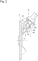
Fig. 2 is a side view ofFig. 1 . -
Fig. 3 is a partial perspective back view of the same drum brake apparatus. -
Fig. 4 is a side view ofFig. 3 . -
Fig. 5 illustrates a bracket member as viewed from arrows 5-5 illustrated inFig. 4 (a plan view of the bracket member). -
Fig. 6 is a cross-sectional view taken along a line 6-6 illustrated inFig. 5 . -
Fig. 7 is a perspective view of the bracket member. -
Fig. 8 is an enlarged view of a portion indicated by anarrow 8 illustrated inFig. 4 . - An embodiment of the present invention will be described with reference to accompanying
Figs. 1 to 8 . - First, in
Figs. 1 to 3 , areference numeral 2 indicates an electric parking drum brake apparatus as an electric brake apparatus according to the present invention, which is mounted on a rear wheel of an automobile. Abackplate 3 as a support member of this electric parkingdrum brake apparatus 2 is supported by a not-illustrated suspension member, and includes acentral hole 4 at the central portion thereof. A rear wheel axle is inserted through thecentral hole 4. A known main brake mechanism and parking brake mechanism including a brake shoe or the like are arranged on the front side of thisbackplate 3. - Further, a
boss 5 is bulgingly formed on a one-side portion of the rear surface of thisbackplate 3. Thisboss 5 includes asupport surface 5a and a through-hole 5b. Thesupport surface 5a slopes downward from a ridge line toward the outer peripheral side of thebackplate 3. The through-hole 5b is opened to thesupport surface 5a. Abracket member 7 is fixed to thebackplate 3 so as to cover thissupport surface 5a, and anelectric actuator 8 is mounted on thisbracket member 7. - An
actuator mechanism 9 of theelectric actuator 8 includes amotor 10, anoutput spindle 11, and a transmission mechanism (not illustrated). Theoutput spindle 11 is arranged adjacent to thismotor 10 with their respective axes Y2 and Y1 in parallel with each other. The transmission mechanism converts a rotational output of themotor 10 into a thrust force and transmits it to the above-describedoutput spindle 11. Anactuator case 12 containing thisactuator mechanism 9 includes a cylindricalmotor case portion 12a (corresponding to a motor portion of the present invention), a cylindricaloutput case portion 12b (corresponding to an output spindle portion of the present invention), and atransmission case portion 12c. Themotor case portion 12a contains the above-describedmotor 10. Theoutput case portion 12b is arranged adjacent to thismotor case portion 12a, and contains the above-describedoutput spindle 11. Thetransmission case portion 12c contains the above-described transmission mechanism, and integrally couples a base portion of the above-describedmotor case portion 12a (a rotational output side of the motor 10) with the above-describedoutput case portion 12b. Themotor case portion 12a shares the axis Y1 with the above-describedmotor 10. Further, theoutput case portion 12b shares the axis Y2 with the above-describedoutput spindle 11. Aconnector 17 for supplying power to themotor 10 is provided at the base portion of themotor case portion 12a. - The
output case portion 12b is formed so as to have a diameter smaller than themotor case portion 12a. Further, thisoutput case portion 12b includes a large-diametercylindrical portion 13 and a small-diametercylindrical portion 14. The large-diametercylindrical portion 13 protrudes beyond the front surface of thetransmission case portion 12c. The small-diametercylindrical portion 14 is coaxially connected to this large-diametercylindrical portion 13 via a steppedportion 15, and is smaller in diameter than the large-diametercylindrical portion 13. The length of thisoutput case portion 12b that protrudes from the front surface of the above-describedtransmission case portion 12c is shorter than the length of the above-describedmotor case portion 12a that protrudes from the front surface of the above-describedtransmission case portion 12c. - A bellows-type
dust prevention boot 16 is provided in a tensioned manner between the distal end portion of the above-described small-diametercylindrical portion 14 and the distal end portion of the above-describedoutput spindle 11 protruding beyond the distal end portion of the small-diametercylindrical portion 14. - On the other hand, the above-described
bracket member 7 is molded using synthetic resin as a whole, and includes abracket base 7a where a plurality offixation pieces 18 each fixed to the above-describedbackplate 3 by afixation member 19 such as a bolt is arranged on the outer periphery thereof as illustrated inFigs. 1 and3 to 7 . Thisbracket base 7a includes a cylindrical first containingtube 21 and a cylindrical second containingtube 22 smaller in diameter than the first containingtube 21, which are integrally molded adjacent to and in parallel with each other. This second containingtube 22 is arranged so as to be supported on thesupport surface 5a of the above-describedboss 5. - A
cylindrical holding tube 24 is provided continuously at the upper end of the above-described second containingtube 22 coaxially and integrally therewith. The holdingtube 24 is thinner than the second containingtube 22. A plurality ofribs 25a (refer toFigs. 5 to 7 ) is formed on the inner peripheral surface of this holdingtube 24 so as to be arranged at even intervals in the circumferential direction of the holdingtube 24. The plurality ofribs 25a extends in the axial direction of the holdingtube 24. Theseribs 25a form a press-fit portion 25, to which the above-describedoutput case portion 12b is press-fitted. Further, a plurality ofreinforcement ribs 26 is integrally formed on the outer peripheral surface of the holdingtube 24. The plurality ofreinforcement ribs 26 is erected from the upper surface of the above-describedbracket base 7a. - Then, the distal end portion of the above-described
motor case portion 12a is inserted in the first containingtube 21. Further, the small-diametercylindrical portion 14 of the above-describedoutput case portion 12b is press-fitted to the above-described plurality ofribs 25a, i.e., the press-fit portion 25 on the inner peripheral surface of the holdingtube 24. A limit on this press-fit is defined by abutment of the steppedportion 15 between the above-described large-diametercylindrical portion 13 and small-diametercylindrical portion 14 with the end surface of the holdingtube 24. - Now, the plurality of
ribs 25a on the inner peripheral surface of the holdingtube 24, which forms the press-fit portion 25, is relatively easily elastically deformable, and therefore facilitates setting of a press-fit interference of the above-described small-diametercylindrical portion 14 and is also effective in avoiding a crack in the holdingtube 24 due to this press-fit. - When the small-diameter
cylindrical portion 14 is press-fitted to the holdingtube 24, the distal end portion of the above-describedoutput spindle 11 protrudes to the front side of thebackplate 3 via the second containingtube 22 and the through-hole 5b of the above-describedboss 5, and a brake cable (not illustrated) leading to the above-described brake mechanism is connected thereto. Thisoutput spindle 11 is configured to be driven so as to be axially advanced/retracted according to a forward/reverse rotation of a rotor of the above-describedmotor 10 to actuate/release the above-described parking mechanism via the above-described brake cable. - An
elastic engagement unit 28 is provided between the small-diametercylindrical portion 14 of the above-describedoutput case portion 12b and the above-describedholding tube 24 including the press-fit portion 25 to which the small-diametercylindrical portion 14 is press-fitted. Theelastic engagement unit 28 locks the press-fit state between the small-diametercylindrical portion 14 and the press-fit portion 25. Thiselastic engagement unit 28 includes a plurality of (two in the illustrated example) protruding engagement portions 29 (refer toFig. 8 ) and a plurality of recessed engagement portions 30 (refer toFig. 6 ). The plurality of protrudingengagement portions 29 is formed on the outer periphery of the small-diametercylindrical portion 14 so as to be arranged at even intervals along the circumferential direction of the small-diametercylindrical portion 14. The plurality of recessedengagement portions 30 is formed on the holdingtube 24, and is elastically engaged with the above-describedprotruding engagement portions 29 when the small-diametercylindrical portion 14 is press-fitted to the press-fit portion 25. - More specifically, each of the protruding
engagement portions 29 includes arectangular guide protrusion 31 and anengagement claw 32. Theguide protrusion 31 bulges from the outer peripheral surface of the small-diametercylindrical portion 14. Theengagement claw 32 is provided in a protruding manner on the front side of thisguide protrusion 31. Thisengagement claw 32 includes aninclined surface 32b and avertical surface 32c. Theinclined surface 32b slopes down from atop portion 32a toward the distal end side of the small-diametercylindrical portion 14. Thevertical surface 32c extends from thetop portion 32a toward the above-describedguide protrusion 31. - On the other hand, each of the recessed
engagement portions 30 includes aguide wall 33 squared U-shaped in cross section, and anengagement hole 34. Theguide wall 33 is formed so as to radially extend a part of the circumferential wall of the above-describedholding tube 24. Theengagement hole 34 is provided to thisguide wall 33. The above-describedguide wall 33 is elastically deformable in the radial direction of the holdingtube 24 because the holdingtube 24 is made from synthetic resin. Especially, the thickness of theguide wall 33 is set to be thinner than the thickness of the holdingtube 24 in the illustrated example to facilitate this elastic deformation. - Then, when the small-diameter
cylindrical portion 14 is press-fitted to the press-fit portion 25 of the holdingtube 24, first, theguide protrusions 31 enter the inner grooves of theguide walls 33, and theinclined surfaces 32b of theengagement claws 32 elastically deform theguide walls 33 radially outward. When the small-diametercylindrical portion 14 reaches the limit on the press-fit between the small-diametercylindrical portion 14 and the press-fit portion 25 of the holdingtube 24, theengagement claws 32 reach the positions where they are engaged with the engagement holes 34 and thevertical surfaces 32c of theengagement claws 32 face the inner surfaces of the engagement holes 34 due to the restoration from the elastic deformation of theguide walls 33. This state is an elastically engaged state of theelastic engagement unit 28, and the press-fit state between the small-diametercylindrical portion 14 and the press-fit portion 25 of the holdingtube 24 is locked thereby. - Further, a pair of left and right recessed
movable rails 37 is formed on the outer surface of themotor case portion 12a. Themovable rails 37 are formed in parallel with the axis Y of themotor case portion 12a. A pair of left and right protruding fixedrails 38, to which thesemovable rails 37 can be engaged, is formed on the outer surface of the above-describedholding tube 24. Sliding engagement between these movable and fixedrails output case portion 12b is fitted to the holdingtube 24, the position at which themotor case portion 12a is contained in the first containingtube 21, and the engageable position of theelastic engagement unit 28, and also prohibits themotor case portion 12a from rotating around the holdingtube 24. - In the illustrated example, each of the fixed rails 38 has a break at an intermediate portion thereof, but the length of this break is shorter than the length of the
movable rail 37, and therefore themovable rail 37 is prevented from being disengaged from the fixedrail 38. It is apparent that the fixedrail 38 may be formed continuously with no break present over the entire length thereof. These movable and fixedrails unit 36 that holds themotor case portion 12a. - Next, the functions of this embodiment will be described.
- When the
electric actuator 8 is mounted on thebracket member 7, first, theactuator case 12 is pressed toward thebracket member 7 with themovable rails 37 of themotor case portion 12a slidingly engaged with the fixedrails 38 of thebracket member 7. Then, due to the positioning and guide function of theserails motor case portion 12a is inserted into the first containingtube 21 of thebracket member 7, and the small-diametercylindrical portion 14 of theoutput case portion 12b is press-fitted to the press-fit portion 25 of the holdingtube 24 of thebracket member 7 at the same time. Further, theguide protrusions 31 of the small-diametercylindrical portion 14 are being engaged with the inner grooves of theguide walls 33 of the holdingtube 24, and theinclined surfaces 32b of theengagement claws 32 elastically deform theguide walls 33 radially outward. When the small-diametercylindrical portion 14 reaches the limit on the press-fit to the press-fit portion 25 of the holdingtube 24, theengagement claws 32 reach the positions where they are engaged with the engagement holes 34, and the restoration from the elastic deformation of theguide walls 33 causes thevertical surfaces 32c of theengagement claws 32 to face the inner surfaces of the engagement holes 34, bringing theelastic engagement unit 28 into the elastically engaged state. As a result, the press-fit state between the small-diametercylindrical portion 14 and the press-fit portion 25 of the holdingtube 24, and the insertion state of themotor case portion 12a in the first containingtube 21 are locked. - In this manner, the
electric actuator 8 can be easily joined to thebracket member 7 by placing theelastic engagement unit 28 into the elastically engaged state with a linear single operation of moving theactuator case 12 to thebracket member 7 side according to the guide function of the fixedrails 38 and themovable rails 37 extending in the axial direction of themotor case portion 12a, and the assemblability thereof is extremely excellent. - In addition, with the
electric actuator 8 joined to thebracket member 7, at least a part of themotor case portion 12a is contained in the first containingtube 21 of thebracket member 7, and therefore theelectric actuator 8 can be less exposed to outside thebracket member 7 and the electric brake apparatus can be reduced in size. - Further, the movable and fixed
rails holding unit 36 can exert a great reaction force against a rotational moment of themotor case portion 12a around the holdingtube 24 with the holdingtube 24 and theoutput case portion 12b joined to each other by the above-describedelastic engagement unit 28, and this can effectively suppress a swinging motion of themotor case portion 12a containing themotor 10 relatively heavy in weight around the holdingtube 24 when the vehicle vibrates, thereby ensuring the durability of theactuator case 12 and also reducing a load imposed on theelastic engagement unit 28 to enhance even the durability of theelastic engagement unit 28. - In this case, laying the movable and fixed
rails motor case portion 12a can contribute to further effectively suppressing a swinging motion of themotor case portion 12a. - Further, the above-described slidingly engaged movable and fixed
rails output case portion 12a is fitted to the holdingtube 24, which leads to contribution to further excellent assemblability. - Further, the above-described
elastic engagement unit 28 is constituted by theengagement claws 32 of theoutput case portion 12b and the engagement holes 34 of the holdingtube 24, and is also formed elastically deformably in the portions thereof surrounding the engagement holes 34 so as to permit the engagement between them. Therefore, thiselastic engagement unit 28 can be simply configured. - Further, the
bracket member 7 can be reduced in weight by being made from synthetic resin, and also can be effectively reinforced by being provided with the above-described first and second containingtubes - Further, press-fitting the
output case portion 12b to the press-fit portion 25 of the holdingtube 24 can enhance the joining strength between theoutput case portion 12b and the holdingtube 24 to ease a load borne by the above-describedelastic engagement unit 28 in a direction for extracting theoutput case portion 12b, thereby achieving the improvement of the durability thereof. - Having described an embodiment of the present invention, the present invention is not limited to the above-described embodiment and can be subjected to various design modifications made without departing from the present invention recited in the claims.
- For example, the above-described
elastic engagement unit 28 can be modified in such a manner that theengagement claw 32 and theengagement hole 34 are provided to the holdingtube 24 and theoutput case portion 12b, respectively, in an opposite manner from the above-described embodiment. Further, themotor case portion 12a can be press-fitted to the first containingtube 21 of the bracket member, and an elastic engagement unit can also be interposed between them. Further, the protrudingrail 37 and the recessedrail 38 forming the holdingunit 36 can be formed on thebracket member 7 and the first containingtube 21, respectively, in an opposite manner from the embodiment. Further, the present invention is also applicable to an electric brake apparatus including an electric actuator, such as an electric parking disk brake apparatus. - The present application claims priority under the Paris Convention to
Japanese Patent Application No. 2022-056883 filed on March 30, 2022 Japanese Patent Application No. 2022-056883 filed on March 30, 2022 -
- 2
- electric brake apparatus (electric parking drum brake apparatus)
- 3
- support member (backplate)
- 7
- bracket member
- 8
- electric actuator
- 9
- actuator mechanism
- 12a
- motor portion (motor case portion)
- 12b
- output spindle portion (output case portion)
- 12c
- transmission case portion
- 21
- containing tube (first containing tube)
- 24
- holding tube
- 25
- press-fit portion
- 28
- elastic engagement unit
- 29
- protruding engagement portion
- 30
- recessed engagement portion
- 36
- holding unit
- 37
- movable rail
- Y1
- axis of motor portion (motor case portion)
- Y2
- axis of output spindle portion (output case portion)
Claims (8)
- An electric brake apparatus comprising:a bracket member (7) fixed to a support member (3) of a brake mechanism; andan electric actuator (8) joined to the bracket member (7) and operable to actuate the brake mechanism,wherein the electric actuator (8) includes a motor portion (12a), andwherein the electric actuator (8) is engaged with the bracket member (7) by inserting the electric actuator (8) into the bracket member (7) along an axial direction of the motor portion (12a).
- The electric brake apparatus according to claim 1, wherein a holding unit (36) configured to hold the motor portion (12a) is provided to the bracket member (7).
- The electric brake apparatus according to claim 2, wherein the holding unit (36) is disposed on a distal end side of the motor portion (12a).
- The electric brake apparatus according to claim 2 or 3, wherein the holding unit (36) has a rail structure.
- The electric brake apparatus according to any one of claims 1 to 4, wherein an elastic engagement unit (28) is provided between the bracket member (7) and the electric actuator (8),wherein the elastic engagement unit (28) includesa protruding engagement portion (29) provided on one of the bracket member (7) and the electric actuator (8) anda recessed engagement portion (30) provided on the other of the bracket member (7) and the electric actuator (8), andwherein first and second engagement portions (29 and 30) are engaged with each other with the aid of elastic deformation of one of the first and second engagement portions (29 and 30).
- The electric brake apparatus according to any one of claims 1 to 5, wherein the electric actuator (8) includes an output spindle portion (12b) arranged in such a manner that axes of the motor portion (12a) and the output spindle portion (12b) extend in parallel with each other, and the output spindle portion (12b) is engaged with a holding tube (24) by fitting the output spindle portion (12b) to the holding tube (24) provided to the bracket member (7).
- The electric brake apparatus according to claim 6, wherein the holding tube (24) includes a press-fit portion (25) to which the output spindle portion (12b) is press-fitted.
- The electric brake apparatus according to any one of claims 1 to 7, wherein the bracket member (7) is made from synthetic resin, and a containing tube (21) configured to contain the motor portion (12a) is molded integrally with the bracket member (7).
Applications Claiming Priority (2)
| Application Number | Priority Date | Filing Date | Title |
|---|---|---|---|
| JP2022056883 | 2022-03-30 | ||
| PCT/JP2023/009212 WO2023189396A1 (en) | 2022-03-30 | 2023-03-10 | Electric brake device |
Publications (2)
| Publication Number | Publication Date |
|---|---|
| EP4502413A1 true EP4502413A1 (en) | 2025-02-05 |
| EP4502413A4 EP4502413A4 (en) | 2025-07-09 |
Family
ID=88200689
Family Applications (1)
| Application Number | Title | Priority Date | Filing Date |
|---|---|---|---|
| EP23779420.1A Pending EP4502413A4 (en) | 2022-03-30 | 2023-03-10 | ELECTRIC BRAKE DEVICE |
Country Status (5)
| Country | Link |
|---|---|
| US (1) | US20250154995A1 (en) |
| EP (1) | EP4502413A4 (en) |
| JP (1) | JP7825705B2 (en) |
| CN (1) | CN118715150A (en) |
| WO (1) | WO2023189396A1 (en) |
Family Cites Families (9)
| Publication number | Priority date | Publication date | Assignee | Title |
|---|---|---|---|---|
| CN103339401B (en) * | 2011-02-02 | 2017-02-15 | 大陆-特韦斯贸易合伙股份公司及两合公司 | Drum brake module which can be operated by electric motor |
| FR3016013B1 (en) * | 2013-12-30 | 2016-02-12 | Chassis Brakes Int Bv | DRUM BRAKE ACTUATOR WITH MOTORIZATION BY EMBOITEMENT WITH ANGULAR GRIP |
| EP2921358B1 (en) * | 2014-03-21 | 2019-05-01 | IMS Gear SE & Co. KGaA | Actuator assembly |
| JP6581152B2 (en) * | 2017-06-23 | 2019-09-25 | 日信工業株式会社 | Electric actuator and electric parking brake device |
| JP6727178B2 (en) * | 2017-10-10 | 2020-07-22 | 日信工業株式会社 | Electric parking brake device |
| JP6603769B2 (en) * | 2018-08-29 | 2019-11-06 | 株式会社ミツバ | Brake actuator and brake device |
| JP7363309B2 (en) * | 2019-09-30 | 2023-10-18 | 株式会社アドヴィックス | connection structure |
| KR102822450B1 (en) * | 2020-06-23 | 2025-06-20 | 현대모비스 주식회사 | Drum break apparatus |
| JP6878665B1 (en) | 2020-09-30 | 2021-06-02 | グンゼ株式会社 | Adhesive sheet for image display device |
-
2023
- 2023-03-10 JP JP2024511656A patent/JP7825705B2/en active Active
- 2023-03-10 EP EP23779420.1A patent/EP4502413A4/en active Pending
- 2023-03-10 CN CN202380024995.2A patent/CN118715150A/en active Pending
- 2023-03-10 US US18/837,401 patent/US20250154995A1/en active Pending
- 2023-03-10 WO PCT/JP2023/009212 patent/WO2023189396A1/en not_active Ceased
Also Published As
| Publication number | Publication date |
|---|---|
| CN118715150A (en) | 2024-09-27 |
| JP7825705B2 (en) | 2026-03-06 |
| US20250154995A1 (en) | 2025-05-15 |
| JPWO2023189396A1 (en) | 2023-10-05 |
| KR20240110873A (en) | 2024-07-16 |
| WO2023189396A1 (en) | 2023-10-05 |
| EP4502413A4 (en) | 2025-07-09 |
Similar Documents
| Publication | Publication Date | Title |
|---|---|---|
| EP3171491B1 (en) | Brushless wiper motor | |
| US7503615B2 (en) | Window wiping device, particularly for a motor vehicle | |
| JP2010530504A (en) | Connecting device and shaft with joint | |
| EP3260724B1 (en) | Actuator for brake, and brake device | |
| US11180120B2 (en) | Actuator for electric parking brake | |
| CN110914558B (en) | Power transmission shaft | |
| KR101637850B1 (en) | Propeller shaft with locking device | |
| CN107605981A (en) | Power transmission shaft | |
| US11459020B2 (en) | Steering systems for a vehicle | |
| US20070295119A1 (en) | Starting device for a thermal engine | |
| US20250154995A1 (en) | Electric brake apparatus | |
| JP6382116B2 (en) | Brake actuator and brake device | |
| JPWO2016104687A1 (en) | Disc brake | |
| EP2220386B9 (en) | Connecting device for transmission cable in vehicle | |
| EP1630429A1 (en) | Conduit end fitting | |
| KR20100118642A (en) | Double clutch | |
| US20190093415A1 (en) | Clutch, motor, and power window device | |
| CN209340364U (en) | Coupling assembly, steering boost system and vehicle | |
| CN104131928B (en) | Motor and the method for installing motor | |
| US11047433B2 (en) | Clutch and motor | |
| KR20200016605A (en) | Actuator | |
| CN118176117A (en) | Wheel bearing unit for a vehicle | |
| CN116829847B (en) | Bearing unit and motor with reducer | |
| US12157445B2 (en) | Actuator for electronic parking brake | |
| JP2008146988A (en) | Connector structure |
Legal Events
| Date | Code | Title | Description |
|---|---|---|---|
| STAA | Information on the status of an ep patent application or granted ep patent |
Free format text: STATUS: THE INTERNATIONAL PUBLICATION HAS BEEN MADE |
|
| PUAI | Public reference made under article 153(3) epc to a published international application that has entered the european phase |
Free format text: ORIGINAL CODE: 0009012 |
|
| STAA | Information on the status of an ep patent application or granted ep patent |
Free format text: STATUS: REQUEST FOR EXAMINATION WAS MADE |
|
| 17P | Request for examination filed |
Effective date: 20240829 |
|
| AK | Designated contracting states |
Kind code of ref document: A1 Designated state(s): AL AT BE BG CH CY CZ DE DK EE ES FI FR GB GR HR HU IE IS IT LI LT LU LV MC ME MK MT NL NO PL PT RO RS SE SI SK SM TR |
|
| A4 | Supplementary search report drawn up and despatched |
Effective date: 20250612 |
|
| DAV | Request for validation of the european patent (deleted) | ||
| DAX | Request for extension of the european patent (deleted) | ||
| RIC1 | Information provided on ipc code assigned before grant |
Ipc: B60T 13/74 20060101ALI20250605BHEP Ipc: F16D 121/24 20120101ALI20250605BHEP Ipc: F16D 65/22 20060101AFI20250605BHEP |
|
| RAP3 | Party data changed (applicant data changed or rights of an application transferred) |
Owner name: ASTEMO, LTD. |
|
| STAA | Information on the status of an ep patent application or granted ep patent |
Free format text: STATUS: EXAMINATION IS IN PROGRESS |
|
| 17Q | First examination report despatched |
Effective date: 20260319 |
|
| GRAP | Despatch of communication of intention to grant a patent |
Free format text: ORIGINAL CODE: EPIDOSNIGR1 |
|
| STAA | Information on the status of an ep patent application or granted ep patent |
Free format text: STATUS: GRANT OF PATENT IS INTENDED |