EP4502287A1 - Swiveling work machine - Google Patents
Swiveling work machine Download PDFInfo
- Publication number
- EP4502287A1 EP4502287A1 EP23780189.9A EP23780189A EP4502287A1 EP 4502287 A1 EP4502287 A1 EP 4502287A1 EP 23780189 A EP23780189 A EP 23780189A EP 4502287 A1 EP4502287 A1 EP 4502287A1
- Authority
- EP
- European Patent Office
- Prior art keywords
- electric motor
- bracket
- hydraulic pump
- connector
- drive shaft
- Prior art date
- Legal status (The legal status is an assumption and is not a legal conclusion. Google has not performed a legal analysis and makes no representation as to the accuracy of the status listed.)
- Pending
Links
Images












Classifications
-
- E—FIXED CONSTRUCTIONS
- E02—HYDRAULIC ENGINEERING; FOUNDATIONS; SOIL SHIFTING
- E02F—DREDGING; SOIL-SHIFTING
- E02F9/00—Component parts of dredgers or soil-shifting machines, not restricted to one of the kinds covered by groups E02F3/00 - E02F7/00
- E02F9/08—Superstructures; Supports for superstructures
- E02F9/0858—Arrangement of component parts installed on superstructures not otherwise provided for, e.g. electric components, fenders, air-conditioning units
- E02F9/0866—Engine compartment, e.g. heat exchangers, exhaust filters, cooling devices, silencers, mufflers, position of hydraulic pumps in the engine compartment
-
- E—FIXED CONSTRUCTIONS
- E02—HYDRAULIC ENGINEERING; FOUNDATIONS; SOIL SHIFTING
- E02F—DREDGING; SOIL-SHIFTING
- E02F3/00—Dredgers; Soil-shifting machines
- E02F3/04—Dredgers; Soil-shifting machines mechanically-driven
- E02F3/28—Dredgers; Soil-shifting machines mechanically-driven with digging tools mounted on a dipper- or bucket-arm, i.e. there is either one arm or a pair of arms, e.g. dippers, buckets
- E02F3/30—Dredgers; Soil-shifting machines mechanically-driven with digging tools mounted on a dipper- or bucket-arm, i.e. there is either one arm or a pair of arms, e.g. dippers, buckets with a dipper-arm pivoted on a cantilever beam, i.e. boom
- E02F3/32—Dredgers; Soil-shifting machines mechanically-driven with digging tools mounted on a dipper- or bucket-arm, i.e. there is either one arm or a pair of arms, e.g. dippers, buckets with a dipper-arm pivoted on a cantilever beam, i.e. boom working downwardly and towards the machine, e.g. with backhoes
- E02F3/325—Backhoes of the miniature type
-
- E—FIXED CONSTRUCTIONS
- E02—HYDRAULIC ENGINEERING; FOUNDATIONS; SOIL SHIFTING
- E02F—DREDGING; SOIL-SHIFTING
- E02F9/00—Component parts of dredgers or soil-shifting machines, not restricted to one of the kinds covered by groups E02F3/00 - E02F7/00
- E02F9/08—Superstructures; Supports for superstructures
- E02F9/0808—Improving mounting or assembling, e.g. frame elements, disposition of all the components on the superstructures
-
- E—FIXED CONSTRUCTIONS
- E02—HYDRAULIC ENGINEERING; FOUNDATIONS; SOIL SHIFTING
- E02F—DREDGING; SOIL-SHIFTING
- E02F9/00—Component parts of dredgers or soil-shifting machines, not restricted to one of the kinds covered by groups E02F3/00 - E02F7/00
- E02F9/08—Superstructures; Supports for superstructures
- E02F9/0858—Arrangement of component parts installed on superstructures not otherwise provided for, e.g. electric components, fenders, air-conditioning units
-
- E—FIXED CONSTRUCTIONS
- E02—HYDRAULIC ENGINEERING; FOUNDATIONS; SOIL SHIFTING
- E02F—DREDGING; SOIL-SHIFTING
- E02F9/00—Component parts of dredgers or soil-shifting machines, not restricted to one of the kinds covered by groups E02F3/00 - E02F7/00
- E02F9/20—Drives; Control devices
- E02F9/2058—Electric or electro-mechanical or mechanical control devices of vehicle sub-units
- E02F9/2062—Control of propulsion units
- E02F9/207—Control of propulsion units of the type electric propulsion units, e.g. electric motors or generators
-
- H—ELECTRICITY
- H01—ELECTRIC ELEMENTS
- H01M—PROCESSES OR MEANS, e.g. BATTERIES, FOR THE DIRECT CONVERSION OF CHEMICAL ENERGY INTO ELECTRICAL ENERGY
- H01M50/00—Constructional details or processes of manufacture of the non-active parts of electrochemical cells other than fuel cells, e.g. hybrid cells
- H01M50/20—Mountings; Secondary casings or frames; Racks, modules or packs; Suspension devices; Shock absorbers; Transport or carrying devices; Holders
- H01M50/249—Mountings; Secondary casings or frames; Racks, modules or packs; Suspension devices; Shock absorbers; Transport or carrying devices; Holders specially adapted for aircraft or vehicles, e.g. cars or trains
-
- B—PERFORMING OPERATIONS; TRANSPORTING
- B60—VEHICLES IN GENERAL
- B60R—VEHICLES, VEHICLE FITTINGS, OR VEHICLE PARTS, NOT OTHERWISE PROVIDED FOR
- B60R16/00—Electric or fluid circuits specially adapted for vehicles and not otherwise provided for; Arrangement of elements of electric or fluid circuits specially adapted for vehicles and not otherwise provided for
- B60R16/02—Electric or fluid circuits specially adapted for vehicles and not otherwise provided for; Arrangement of elements of electric or fluid circuits specially adapted for vehicles and not otherwise provided for electric constitutive elements
- B60R16/04—Arrangement of batteries
-
- E—FIXED CONSTRUCTIONS
- E02—HYDRAULIC ENGINEERING; FOUNDATIONS; SOIL SHIFTING
- E02F—DREDGING; SOIL-SHIFTING
- E02F9/00—Component parts of dredgers or soil-shifting machines, not restricted to one of the kinds covered by groups E02F3/00 - E02F7/00
- E02F9/08—Superstructures; Supports for superstructures
- E02F9/0833—Improving access, e.g. for maintenance, steps for improving driver's access, handrails
Definitions
- a swivel working machine disclosed in Patent Literature 1 includes a swivel base, a hydraulic device provided on a swivel base, a battery, an electric motor driven by electricity outputted by a battery, and a hydraulic pump to be driven by the electric motor to deliver hydraulic fluid, and the battery includes a main secondary battery and an auxiliary secondary battery.
- the main secondary battery is provided at the central portion of the swivel base
- the hydraulic pump and the electric motor are provided at the rear portion of the swivel base
- the auxiliary secondary battery is provided at a side portion of the swivel base.
- the support portion may support the electric motor and the hydraulic pump arranged in a front-rear direction, and the plurality of mounting devices may each be located outward of the electric motor, the hydraulic pump and the support portion in plan view under the conditions in which the electric motor and the hydraulic pump are attached to the support portion.
- the connector may include a first connector portion attached to one of the shafts, a second connector portion attached to the other of the shafts, and an elastic body connecting the first connector portion and the second connector portion.
- the electric working machine may further include a housing to surround the connector at a position radially outward of the connector under the conditions in which the electric motor and the hydraulic pump are attached to the support portion, wherein, under the conditions in which the connector is attached to the electric motor or the hydraulic pump that has the one of the shafts and attached to the support portion, the electric motor or the hydraulic pump that has the other of the shafts may be removable from the connector by moving the connector in the axial direction of the shaft.
- a method of assembling an electric working machine is a method of assembling an electric working machine including an electric motor to rotate a drive shaft, a hydraulic pump including an input shaft to receive input of power from the drive shaft and configured to be driven by power inputted into the input shaft via the drive shaft to deliver hydraulic fluid, a connector to connect the drive shaft and the input shaft, and a support portion to support the electric motor and the hydraulic pump, the method including a first step including attaching the connector to one of the drive shaft and the input shaft such that the connector is rotatable together with the one of the drive shaft and the input shaft and is restricted from moving in the axial direction, and a second step including attaching, to the connector, the other of the drive shaft and the input shaft such that the other of the drive shaft and the input shaft is rotatable together with the connector and is not restricted from moving in the axial direction.
- the outer diameter of the connector may be greater than the inner diameter of the socket hole.
- a working machine includes a swivel base, a battery unit, an electric motor to rotate a drive shaft using electricity outputted from the battery unit, a hydraulic pump including an input shaft to receive input of power from the drive shaft and configured to be driven by power inputted into the input shaft from the drive shaft to deliver hydraulic fluid, a support portion to support the electric motor and the hydraulic pump on or above the swivel base, and a second bracket provided independently of the electric motor to connect the electric motor and the support portion, wherein a structure in which the second bracket is attached to the hydraulic pump is attached to the support portion via the second bracket.
- the second bracket may include a second extension portion extending outward in a radial direction of the input shaft relative to the hydraulic pump, and the second extension portion may include a second connected portion connected to the support portion.
- the second connected portion may be a hole to have a fastener inserted therethrough, and the second bracket and the support portion may be connected by the fastener.
- the second bracket may be provided with a first portion-for attachment to attach a first hoisting attachment.
- the swivel working machine may include a connector to connect the drive shaft and the input shaft, the hydraulic pump may be attached to the support portion via the second bracket, and the support portion may be a housing to, under the conditions in which the connector is attached to the input shaft, surround the connector at a position radially outward of the connector.
- a method of assembling a swivel working machine is a method of assembling a swivel working machine including an electric motor to rotate a drive shaft, a hydraulic pump including an input shaft to receive input of power from the drive shaft and configured to be driven by power inputted into the input shaft from the drive shaft to deliver hydraulic fluid, a support portion to support the electric motor and the hydraulic pump, and a second bracket provided independently of the hydraulic pump to connect the hydraulic pump and the support portion, the method including a first step including attaching the second bracket to the hydraulic pump, and a second step including attaching the second bracket and the hydraulic pump assembled in the first step to the support portion.
- An electric working machine (swivel working machine) according to an aspect of the present invention includes a machine body, a support body provided on the machine body, a battery unit to be placed on the support body, and an electric motor to be driven by electricity outputted from the battery unit, wherein the support body includes a plurality of long plate members for placement of an outer peripheral portion of a bottom of the battery unit, and surfaces for placement of the battery unit of the long plate members are smoothened by machining.
- Portions of the support body that are other than the surfaces for placement of the plate members may not be subjected to the machining.
- the plate members may be subjected to the machining after the plate members are fixed to the frame member by welding,.
- the plurality of plate members may be spaced from each other and fixed to the frame member.
- the battery unit may include a plurality of batteries, the first connector plate may have placed thereon two adjacent ones of the plurality of batteries, and have a vent hole between the two adjacent ones of the plurality of batteries.
- the support body may include a retainer provided on the first plate portion or the second plate portion to fix the battery unit, and the retainer may be attached such that the retainer is adjustable in the front-rear direction.
- FIG. 1 is a side view schematically illustrating a swivel working machine 1.
- FIG. 2 is a plan view schematically illustrating the swivel working machine 1.
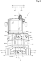
- FIG. 3 is a rear view schematically illustrating the swivel working machine 1.
- the swivel working machine 1 is a backhoe including, for example, a swivel base (machine body) 2, a lower carrier 10, and a working device 20.
- the swivel working machine 1 is an electric working machine driven by electricity.
- An operator's seat 8 where the operator can sit is provided on the swivel base 2, and the operator's seat 8 is enclosed by a protection structure 85.
- the direction that the operator sitting on the operator's seat 8 of the swivel working machine 1 is facing is referred to as front, and the opposite direction (direction of arrow A2 in FIGS. 1 and 2 ) is referred to as rear.
- the left side of the operator is referred to as left, and the right side of the operator (far side in FIG. 1 , and direction of arrow B2 in FIGS. 2 and 3 ) is referred to as right.
- the horizontal direction perpendicular to the front-rear direction is referred to as a width direction (see FIGS. 2 and 3 ), and the direction from the widthwise center of the swivel base 2 to the right or left is referred to as an outward width direction.
- the swivel base 2 is rotatable about a swivel axis (vertical axis) X extending in the up-down direction.
- the swivel base 2 is supported on the lower carrier 10 via a swiveling bearing 3 such that the swivel base 2 is rotatable about the swivel axis X (rotatable leftward and rightward).
- the center of the swiveling bearing 3 is the swiveling axis X (swiveling center), and a swivel motor (not illustrated) is attached to the swivel base 2.
- This swivel motor is a hydraulic device M to be driven by hydraulic fluid delivered by a hydraulic pump 92, and is a motor to drive the swivel base 2 to rotate about the swivel axis X.
- the swivel base 2 is provided with an exterior cover (cover) 80, bracket(s), stays(s)m and the like.
- the exterior cover 80 defines a space (rear room) R at a rear portion of the swivel base 2 for devices, tanks, and other components on the swivel base 2.
- Bracket(s), stay(s) and the like are configured to attach the components and the like.
- the lower carrier 10 includes a travel frame 11 and travel mechanism(s) 12.
- the travel frame (truck frame) 11 is a structure on which the travel mechanism(s) 12 is/are attached and which supports the swivel base 2 on an upper portion thereof.
- Each travel mechanism 12 is, for example, a crawler travel mechanism.
- the travel mechanism 12 includes an idler 13, a driving wheel 14, a plurality of track rollers 15, an endless crawler belt 16, and a travel-related hydraulic device M (travel motor ML, MR) to be driven by hydraulic fluid delivered by the hydraulic pump 92.
- the travel motors ML, MR are hydraulic motors, and each cause a corresponding crawler belt 16 to rotate circumferentially by driving a corresponding driving wheel 14.
- a front portion of the lower carrier 10 is provided with a dozer device 18 driven to move up and down by the extension and retraction of a dozer cylinder C5 (M) which is a hydraulic cylinder (hydraulic actuator).
- the working device 20 is provided at a front portion of the swivel base 2.
- the working device 20 includes a boom 21, an arm 22 and a bucket (working tool) 23.
- the proximal end of the boom 21 is pivotally attached to a swing bracket 24 such that the boom 21 is rotatable about a lateral axis (axis extending in the width direction) and that the boom 21 is swingable up and down (vertical direction).
- the arm 22 is pivotally attached to the distal portion of the boom 21 such that the arm 22 is rotatable about a lateral axis and that the arm 22 is swingable forward and rearward or up and down.
- the bucket 23 is provided at the distal portion of the arm 22 such that the bucket 23 is capable of shoveling and dumping.
- the swivel working machine 1 is configured to attach thereto other working tools (hydraulic attachments) to be driven by hydraulic fluid, instead of or in addition to the bucket 23.
- working tools include hydraulic breakers, hydraulic crushers, angle brooms, earth augers, pallet forks, sweepers, mowers, and snow blowers.
- the swivel working machine 1 includes work-related hydraulic devices M to be driven by hydraulic fluid delivered by the hydraulic pump 92, and the working device 20 is driven by operation of the work-related hydraulic devices M.
- the hydraulic devices M include a swing cylinder C1, a boom cylinder C2, an arm cylinder C3, and a bucket cylinder C4.
- the swing cylinder C1, the boom cylinder C2, the arm cylinder C3 and the bucket cylinder C4 each include a hydraulic cylinder (hydraulic actuator).
- the swing bracket 24 is swingable by the extension and retraction of the swing cylinder C1 provided at a right portion of the swivel base 2.
- the boom 21 is swingable by the extension and retraction of the boom cylinder C2.
- the arm 22 is swingable by the extension and the retraction of the arm cylinder C3.
- the bucket 23 is capable of shoveling and dumping by the extension and retraction of the bucket cylinder C4.
- the hydraulic devices M included in the swivel working machine 1 include the swivel motor, the travel motors ML and MR, the swing cylinder C1, the boom cylinder C2, the arm cylinder C3, the bucket cylinder C4, and the dozer cylinder C5.
- FIG. 4 is a front left perspective view showing the swivel base 2.
- FIG. 5 is a rear right perspective view showing the swivel base 2.
- the swivel base 2 includes a swivel board (board) 30, a plurality of vertical ribs 31 (first vertical rib 31a, second vertical rib 31b, and third vertical rib 31c), a support bracket 32, a partition plate 33, a lateral rib 34, and a support frame 35.
- the swivel board 30 includes a thick steel plate, and the plate is positioned such that the plate surfaces face up and down.
- the swivel board 30 is supported on the lower carrier 10 via the swiveling bearing 3 such that the swivel board 30 is rotatable about the swivel axis X.
- the first vertical rib 31a, the second vertical rib 31b, and the third vertical rib 31c are components to reinforce the swivel board 30, and are provided to extend in the front-rear direction of the swivel board 30.
- the first vertical rib 31a and the second vertical rib 31b are provided upright on the swivel board 30 and are separated from each other in the width direction.
- the first vertical rib 31a is provided at a left portion of the swivel board 30, and the second vertical rib 31b is provided at a right portion of the swivel board 30.
- the third vertical rib 31c is provided between the first vertical rib 31a and the second vertical rib 31b, and is provided to extend from a rear portion of the swivel board 30 to the partition plate 33.
- the support bracket 32 is provided at front portions of the first vertical rib 31a and the second vertical rib 31b. As shown in FIG. 4 , the support bracket 32 and the front portions of the first vertical rib 31a and the second vertical rib 31b are displaced from the widthwise center of the swivel board 30 to the right. As shown in FIG. 1 , the swing bracket 24 is attached to the support bracket 32 such that the swing bracket 24 is rotatable on a vertical axis (axis extending in the up-down direction).
- the partition plate 33 is a component to define a front lower side of the rear room R.
- the partition plate 33 is positioned such that the plate surfaces face forward and rearward and extends one of opposite sides in the width direction (left side) to the other of the opposite sides (right side) at the central portion of the swivel board 30.
- the support frame 35 is provided upright on the rear portion of the swivel board 30 and is located rearward of the partition plate 33.
- the rear portion of the support frame 35 is located rearward of the rear portion of the lower carrier 10.
- the support frame 35 is provided inside the rear room R, and supports the exterior cover 80 and surrounding component(s) provided inside the exterior cover 80.
- the support frame 35 includes a plurality of leg components provided upright on the swivel board 30 (first leg 35a, second leg 35b, third leg 35c, fourth leg 35d, and fifth leg 35e), a first rod member 35h, and a second rod member 35i.
- the first leg 35a is provided upright at a front left of the rear room R.
- the first leg 35a is provided upright at a front portion of a first base 40a which is provided at a left rear of the first vertical rib 31a.
- the first base 40a extends from the partition plate 33 to the lateral rib 34.
- the first leg 35a includes a lower portion extending upward from the first base 40a, an intermediate portion extending diagonally rearward and upward, and an upper portion bent and extending rearward.
- the second leg 35b is provided upright at a front right of the rear room R.
- the second leg 35b is provided upright on a second base 40b which is attached to a rear right portion of the partition plate 33. That is, the lower end of the second leg 35b is located forward of the lower end of the first leg 35a.
- the second leg 35b includes a lower portion extending upward from the second base 40b, an intermediate portion extending diagonally upward and rearward, and an upper portion bent and extending rearward.
- the third leg 35c is provided upright at a rear left of the rear room R.
- the third leg 35c is provided upright at a central portion of the first base 40a.
- the third leg 35c includes a lower portion extending upward from the first base 40a to reach the upper portion of the first leg 35a.
- the fourth leg 35d is provided upright at a rear portion of the rear room R.
- the fourth leg 35d is provided at a rear left portion of the rear room R, and is located inward (rightward) of the third leg 35c in the width direction.
- the fourth leg 35d is provided upright on a third base 40c which is provided at a left portion of the lateral rib 34.
- the fourth leg 35d includes a lower portion extending upward from the third base 40c, an intermediate portion extending diagonally upward and forward, and an upper portion bent and extending forward.
- the fifth leg 35e is provided upright at a rear portion of the rear room R.
- the fifth leg 35e is provided upright at a right rear portion of the rear room R, and is provided on a fourth base 40d which is provided at a right portion of the lateral rib 34.
- the fifth leg 35e includes a lower portion extending upward from the fourth base 40d, an intermediate portion extending diagonally upward and forward, and an upper portion bent and extending forward.
- the upper end of the fourth leg 35d and the upper end of the fifth leg 35e are connected by a connector plate 35f extending in the width direction.
- the connector plate 35f is provided with a pair of support beams 35g extending from the front edge of the connector plate 35f in the front direction.
- the pair of support beams 35g are spaced in the width direction such that the support beams 35g correspond to the upper end of the fourth leg 35d and the upper end of the fifth leg 35e.
- the rear portion of the fourth leg 35d and the rear portion of the fifth leg 35e are located rearward of the rear portion of the lower carrier 10.
- the first rod member 35h and the second rod member 35i are positioned such that their plate surfaces face upward and rearward and that the first rod member 35h and the second rod member 35i each extend in the width direction.
- the first rod member 35h is located forward of the second rod member 35i.
- the first rod member 35h and the second rod member 35i are placed on and fixed to the upper portion of the first leg 35a, the upper portion of the second leg 35b, the upper end of the left support beam 35g, and the upper end of the right support beam 35g.
- the first rod member 35h supports a rear portion of the protection structure 85.
- the second rod member 35i supports the exterior cover 80.
- FIG. 6 is a plan view showing the lower carrier 10, the swivel board 30, and various devices and the like provided on the swivel board 30.
- FIG. 7 is a right front perspective view showing the swivel board 30, a battery unit 90, an electric motor 91, a hydraulic pump 92, and electrical component(s) 93.
- the swivel working machine 1 includes the battery unit 90, the electric motor 91, the hydraulic pump 92, and the electrical component(s) 93.
- the battery unit 90, the electric motor 91, the hydraulic pump 92, and the electrical component(s) 93 are provided on the swivel base 2.
- the battery unit 90 is a structure that can store electricity and output the stored electricity.
- the battery unit 90 includes a plurality of batteries 90a.
- the plurality of batteries 90a are connected in parallel to each other.
- the plurality of batteries 90a can store electricity and are, for example, secondary batteries such as lithium-ion batteries or lead storage batteries.
- the plurality of batteries 90a each include a housing made of a flat steel sheet, and a plurality of cells provided inside that housing, and the plurality of cells are connected electrically in series and/or in parallel.
- the battery unit 90 includes two batteries 90a.
- the battery unit 90 need only include a plurality of batteries 90a, and the number of batteries included in the battery unit 90 is not limited to two.
- the number of batteries included in the battery unit 90 may be an even number other than two or three.
- the plurality of batteries 90a are arranged adjacent to each other in the width direction, and are connected by a coupling bracket 90b.
- the electric motor 91 is a drive source driven by electricity outputted from the battery unit 90 to rotate a drive shaft 91a.
- the electric motor 91 is an interior permanent magnet three-phase AC synchronous motor.
- the electric motor 91 includes a rotatable rotor (rotator) and a stator to generate a force to cause the rotor to rotate.
- the electric motor 91 may be another type of synchronization motor, an alternative-current (AC) motor, or a direct-current motor.
- the electric motor 91 causes the drive shaft 91a to rotate, and the drive shaft 91a transmits the driving force to the hydraulic pump 92.
- the drive shaft 91a is a splined shaft having a splined outer surface.
- the hydraulic pump 92 includes an input shaft 92a to receive input of power from the drive shaft 91a, and the power inputted from the drive shaft 91a into the input shaft 92a drives the input shaft 92a to deliver hydraulic fluid.
- the input shaft 92a is connected to the drive shaft 91a of the electric motor 91, and is driven by the driving force transmitted from the drive shaft 91a.
- the input shaft 92a is a splined shaft having a splined outer surface.
- the splines on the drive shaft 91a and the input shaft 92a may be referred to as external splines.
- the electrical component(s) 93 are, for example, device(s) connected directly or indirectly to the battery unit 90 and transmit(s) the electricity supplied by the battery unit 90 or is/are actuated by the electricity.
- the electrical component(s) 93 include, for example, a junction box 93a, an inverter 93b, and a DC/DC converter 93c.
- the junction box 93a is connected to the battery unit 90 and to other device(s) including the inverter 93b, and transmits the electricity supplied by the battery unit 90 to other device(s).
- the inverter 93b is provided on an electricity supply route from the battery unit 90 to the electric motor 91, and regulates the electricity outputted to the electric motor 91.
- the inverter 93b is a device to drive the electric motor 91, and convert direct current electricity into three phrase AC electricity and supply the three phrase AC electricity to the electric motor 91.
- the inverter 93b is configured to freely change the electric current or voltage of the electricity supplied to the electric motor 91.
- the DC/DC converter 93c converts the voltage of the inputted direct electric current into a different voltage.
- the DC/DC converter 93c is a step-down converter to convert the inputted voltage into a lower voltage.
- the DC/DC converter 93c is, for example, provided in or on the swivel working machine 1, and supplies electricity to an in-vehicle battery (not illustrated) to supply power to electronic equipment.
- the battery unit 90 is provided at the widthwise center of the rear portion of the swivel base 2. Specifically, the battery unit 90 extends from an intermediate portion in the front-rear direction of the swivel base 2 to the rear portion of the swivel base 2. That is, the rear portion of the battery unit 90 is located rearward of the rear portion of the lower carrier 10. As shown in FIG. 2 , the battery unit 90 is positioned such that the position of the center of gravity thereof is displaced in a first direction (leftward) from the widthwise central line Y of the swivel base 2, and is located rearward of the protection structure 85.
- the outer perimeter of the battery unit 90 is surrounded by the support frame 35.
- the lower end of the first leg 35a and the lower end of the second leg 35b are positioned forward of the battery unit 90.
- the third leg 35c is positioned leftward of the battery unit 90.
- the lower end of the fourth leg 35d and the lower end of the fifth leg 35e are positioned rearward of the battery unit 90.
- the upper end of the first leg 35a, the upper end of the second leg 35b, the upper end of the fourth leg 35d, the upper end of the fifth leg 35e, the pair of support beams 35g, the first rod member 35h and the second rod member 35i are positioned above the battery unit 90.
- the electric motor 91 and the hydraulic pump 92 are displaced in a second direction (rightward) from the widthwise center line Y of the swivel base 2 and, as shown in FIGS. 6 and 7 , arranged in the front-rear direction at one side of the battery unit 90.
- the electric motor 91 and the hydraulic pump 92 are provided at a lower portion of the space sideward of (rightward of) the battery unit 90. More specifically, as shown in FIG. 6 , the electric motor 91 and the hydraulic pump 92 are located rightward of the lower end of the second leg 35b.
- the electric motor 91 is provided rearward of the hydraulic pump 92, and is positioned such that the drive shaft 91a is directed in the front-rear direction.
- the hydraulic pump 92 is positioned such that the input shaft 92a is directed in the front-rear direction and that the axis of the input shaft 92a coincides with the axis of the drive shaft 91a.
- the hydraulic pump 92 is located forward of the electric motor 91. As shown in FIG. 2 , a hydraulic fluid tank 94 which stores hydraulic fluid to be sucked by the hydraulic pump 92 is provided in front of that hydraulic pump 92. The front portion of the hydraulic fluid tank 94 is provided with a control valve 95 to regulate the flow rate of hydraulic fluid supplied to the hydraulic device(s) M.
- the electrical components 93 are provided above the battery unit 90 and are arranged in the width direction.
- the battery unit 90 is provided below the electrical components 93, and the swivel base 2, the battery unit 90, and the electrical components 93 are provided in this order in the bottom-to-top direction. That is, the relatively heavy battery unit 90 is located lower than the electrical components 93, and is located at a low position in the swivel working machine 1.
- the swivel working machine 1 includes a support body 50, a upright frame 56, and a support portion 65.
- the support body 50 is a structure to support the battery unit 90 on or above the swivel base 2.
- FIG. 8 is a left front perspective view showing the support body 50.
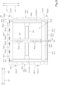
- FIG. 9 is a plan view showing the support body 50.
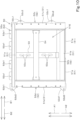
- FIG. 10 is a bottom view showing the support body 50.
- the support body 50 includes a thick steel sheet or the like.
- the support body 50 is provided on the swivel base 2 such that the sheet surfaces face upward and downward.
- the support body 50 is fixed to the swivel base 2 via fastener(s) V such as bolt(s). That is, the support body 50 is attached to the swivel base 2 such that the support body 50 cannot move relative to the swivel base 2.
- the support body 50 includes a frame member 51 and a plurality of plate members 52.
- the frame member 51 connects the plurality of plate members 52 together.
- the frame member 51 connects the plurality of plate members 52 such that the upper faces of the plurality of plate members 52 are flush with each other.
- the frame member 51 includes a front frame 51a, a front frame 51a, a rear frame 51b, and a pair of a lateral frames 51c and 51d.
- the front frame 51a, the rear frame 51b, and the pair of lateral frames 51c and 51d are long frames each having a substantially L shaped cross section obtained by bending a thick steel.
- the front frame 51a defines the front end portion of the frame member 51, and is positioned such that the lengthwise direction thereof matches the width direction.
- the rear frame 51b defines the rear end portion of the frame member 51, and is positioned such that the lengthwise direction thereof matches the width direction.
- the rear frame 51b is spaced from the front frame 51a in the front-rear direction.
- the pair of lateral frames 51c and 51d are spaced from each other in the width direction.
- the pair of lateral frames 51c and 51d respectively define one of opposite end portions in the width direction (left end portion) of the frame member 51 and the other of the opposite end portions (right end portion) of the frame member 51, and are positioned such that the lengthwise direction thereof matches the front-rear direction. That is, the frame member 51 is, in plan view, substantially in the form of a number sign (#)defined by the front frame 51a, the pair of lateral frames 51c and 51d, and the rear frame 51b.
- the frame member 51 includes an opening 51E at a central portion thereof. Note that the front frame 51a, the pair of lateral frames 51c and 51d, and the rear frame 51b need only connect the plurality of plate members 52, and may be connected together directly such as by welding, or may be connected indirectly via the plurality of plate members 52.
- the frame member 51 includes a pair of mount brackets 51e.
- the pair of mount brackets 51e are provided at one of opposite portions in the width direction (left portion) of the frame member 51 and the other of the opposite portions (right portion) of the frame member 51.
- the pair of mount brackets 51e are located at the rear end portion of the frame member 51.
- the left mount bracket 51e connects the rear end portion of the left lateral frame 51c and the rear portion of the rear frame 51b, and extends upward.
- the right mount bracket 51e connects the rear end portion of the right lateral frame 51d and the rear portion of the rear frame 51b, and extends upward.
- the pair of mount brackets 51e are fixed to a lower portion of a rear portion of the battery unit 90 via fastener(s) such as bolt(s).
- the frame member 51 is fixed to lower surfaces and/or side surfaces of the plate members 52 by welding.
- the plate members 52 are long flat components, and have placed thereon the outer peripheral portion of the bottom of the battery unit 90.
- the surfaces for placement of the battery unit 90 (hereinafter may be referred to as "placement surfaces") of the plate members 52 (surfaces on which the battery unit 90 is placed) (hatched portions in FIG. 8 ) are smoothened by machining.
- the support body 50 is not subjected to the machining, except for the placement surfaces of the plate members 52.
- the plate members 52 are fixed to the frame member 51 and then subjected to machining.
- the battery unit 90 is placed on the upper surfaces of the plate members 52, and therefore the placement surfaces are the upper surfaces of the plate members 52.
- the plurality of plate members 52 are spaced from each other and fixed to the frame member 51.
- the lower surfaces and/or side surfaces of the plate members 52 are fixed to the frame member 51 by welding.
- the plurality of plate members 52 are four plate members 52 including a first plate portion 52a, a second plate portion 52b, a third plate portion 52c, and a fourth plate portion 52d. Note that the number of the plurality of plate members 52 is not limited to four, and may be three or five.
- the first plate portion 52a is for placement of a front edge portion of the battery unit 90.
- the first plate portion 52a is for placement of the front edge portions of a plurality of batteries 90a.
- the first plate portion 52a is provided at a front edge portion of the support body 50, and is positioned such that the longitudinal direction thereof matches the width direction.
- the first plate portion 52a is connected to the third plate portion 52c and the fourth plate portion 52d via the front frame 51a.
- the lower surface and/or a side surface of the first plate portion 52a is/are fixed to the front frame 51a and to the pair of lateral frames 51c and 51d by welding.
- both the lower surface and a side surface of the first plate portion 52a are fixed to the front frame 51a and to the pair of lateral frames 51c and 51d by welding.
- the first plate portion 52a includes, in a front portion thereof, hole(s) 52a1 passing therethrough in the up-down direction, and cutout(s) 52a2 extending from its front edge portion rearward.
- the holes 52a1 are arranged over an area from one of the opposite ends in the width direction (left end) of the first plate portion 52a to the other of the opposite ends (right end) of the first plate portion 52a.
- the cutouts 52a2 are arranged over the area from one of the opposite ends in the width direction (left end) of the first plate portion 52a to the other of the opposite ends (right end) of the first plate portion 52a.
- the cutouts 52a2 are each provided between adjacent holes 52a1.
- the first plate portion 52a is substantially in the form of a comb.
- the rear edge portion of the battery unit 90 is placed on the second plate portion 52b.
- rear edge portions of the plurality of batteries 90a are placed on the second plate portion 52b.
- the second plate portion 52b is provided at a rear edge portion of the support body 50, and is positioned such that the longitudinal direction thereof matches the width direction.
- the second plate portion 52b is connected to the third plate portion 52c and the fourth plate portion 52d via the rear frame 51b.
- the lower surface and/or a side surface of the second plate portion 52b is/are fixed to the rear frame 51b and the pair of lateral frames 51c and 51d by welding.
- both the lower surface and a side surface of the second plate portion 52b are fixed to the rear frame 51b and the pair of lateral frames 51c and 51d by welding.
- One of the opposite edge portions in the width direction (left edge portion) of the battery unit 90 is placed on the third plate portion 52c.
- the left edge portion of one of the plurality of batteries 90a that is located at one of opposite sides in the width direction (leftmost battery 90a) is placed on the third plate portion 52c.
- the third plate portion 52c is provided at a left edge portion of the support body 50 and is positioned such that the longitudinal direction thereof matches the front-rear direction.
- the third plate portion 52c is connected to the first plate portion 52a and the second plate portion 52b via the pair of lateral frames 51c and 51d.
- the lower surface and/or a side surface of the third plate portion 52c is/are fixed to the front frame 51a and the left one of the lateral frames 51c and 51d by welding.
- both the lower surface and a side surface of the third plate portion 52c are fixed to the front frame 51a and the left one of the lateral frames 51c and 51d by welding.
- the third plate portion 52c includes first attached portion(s) 52c1 to be fixed to the swivel base 2 via fastener(s) V such as bolt(s).
- Each first attached portion 52c1 extends outward along the width direction (leftward), and has a hole 52c2 passing therethrough in the up-down direction.
- the hole 52c2 has a fastener V inserted therein, and the fastener V is fastened to the first base 40a.
- a plurality of the first attached portions 52c1 are provided near a front end portion of the third plate portion 52c and near a rear end portion of the third plate portion 52c.
- the other of the opposite edge portions in the width direction (right edge portion) of the battery unit 90 is placed on the fourth plate portion 52d.
- the right edge portion of one of the plurality of batteries 90a that is located at the other of the opposite ends in the width direction (rightmost battery 90a) is placed on the fourth plate portion 52d.
- the fourth plate portion 52d is provided at a right edge portion of the support body 50, and is positioned such that the longitudinal direction thereof matches the front-rear direction.
- the fourth plate portion 52d is connected to the first plate portion 52a and the second plate portion 52b via the pair of lateral frames 51c and 51d.
- the lower surface and/or a side surface of the fourth plate portion 52d is/are fixed to the front frame 51a and the right one of the lateral frames 51c and 51d by welding.
- both the lower surface and a side surface of the fourth plate portion 52d are fixed to the front frame 51a and the right one of the lateral frames 51c and 51d by welding.
- the fourth plate portion 52d includes second attached portion(s) 52d1 to be fixed to the swivel base 2 via fastener(s) V such as bolt(s).
- Each second attached portion 52d1 extends outward along the width direction (rightward), and has a hole 52d2 passing therethrough in the up-down direction.
- the hole 52d2 has a fastener V inserted therein, and the fastener V is fastened to a fifth base 40e provided at a right rear portion of the second vertical rib 31b and a sixth base 40f attached at a right end of the lateral rib 34.
- a plurality of the second attached portions 52d1 are provided at a front end portion of the fourth plate portion 52d and a rear end portion of the fourth plate portion 52d. That is, the front second attached portion 52d1 is located forward of the front first attached portion 52c 1, and the rear second attached portion 52d1 is located rearward of the rear first attached portion 52c 1.
- the support body 50 includes a first connector plate 53 and a second connector plate 54.
- the first connector plate 53 is a long frame to connect a widthwise central portion of the first plate portion 52a and a widthwise central portion of the second plate portion 52b.
- the first connector plate 53 includes a thick steel sheet thinner than the plate members 52, and the rear end portion of the first connector plate 53 is connected to the lower surface at the widthwise central portion of the second plate portion 52b.
- the rear end portion of the first connector plate 53 extends forward from the second plate portion 52b, is bent upward, is bent forward, and reaches the first plate portion 52a such that the upper surface is flush with the plurality of plate members 52.
- the lower surface and a side surface of the front end portion of the first connector plate 53 are fixed to the rear edge portion of the first plate portion 52a by welding. Adjacent two of the plurality of batteries 90a are placed on the first connector plate 53.
- the second connector plate 54 is a long frame which passes through the center of the opening 51E in the central portion of the frame member 51 and extends from one of the opposite sides in the widthwise direction (left side) of the frame member 51 to the other of the opposite sides (right sides) of the frame member 51.
- the left end portion of the second connector plate 54 is connected to the central portion in the front-rear direction of the third plate portion 52c, and the right end portion of the second connector plate 54 is connected to the central portion in the front-rear direction of the fourth plate portion 52d.
- the first connector plate 53 and the second connector plate 54 are perpendicular to each other.
- first connector plate 53 and the second connector plate 54 are not machined, and that the plate members 52 are machined before the first connector plate 53 and the second connector plate 54 are attached to the plate members 52 but after the plate members 52 are fixed to the frame member 51.
- FIG. 11 illustrates how the retainers 55 move.
- each retainer 55 is attached to the first plate portion 52a using fastener(s) such as bolt(s) and nut(s), and the fastener(s) is/are fastened to the hole(s) 52a1 in the front portion of the first plate portion 52a.
- the retainer 55 is a member having a substantially L-shaped cross section including a first fixing portion 55a and a second fixing portion 55b extending upward from the first fixing portion 55a.
- the first fixing portion 55a includes a through-hole 55a1 passing therethrough in the up-down direction and elongated in the front-rear direction.
- the second fixing portion 55b includes a through-hole 55b1 passing therethrough in the front-rear direction and elongated in the width direction.
- the second fixing portion 55b is attached and fixed to the lower portion of the rear portion of the battery unit 90 using fastener(s) such as bolt(s). Note that in the case where the pair of mount brackets 51e are provided at the front portion of the frame member 51, the retainers 55 are attached to the second plate portion 52b.
- the upright frame 56 includes a first upright portion 56L, a second upright portion 56R, and a coupling stay 56U.
- FIG. 12 is a left rear perspective view showing the support body 50, the first upright portion 56L, the second upright portion 56R, and the like.
- the first upright portion 56L is provided upright on the upper portion of the third plate portion 52c and, as shown in FIG. 7 , supports one side of the battery unit 90.
- the first upright portion 56L is a plate that includes a thick steel sheet or the like.
- the first upright portion 56L supports the battery unit 90 such that the first upright portion 56L supports the entire dimension in the front-rear direction at one of opposite sides in the width direction (left side) of the battery unit 90.
- the second upright portion 56R is provided upright on the upper portion of the fourth plate portion 52d and, as shown in FIG. 7 , supports the opposite side (right side) of the battery unit 90.
- the second upright portion 56R is a plate that includes a thick steel sheet or the like.
- the second upright portion 56R supports the battery unit 90 such that the second upright portion 56R supports the entire dimension in the front-rear direction at the other of the opposite sides in the width direction (right side) of the battery unit 90. That is, the battery unit 90 is held between the first upright portion 56L and the second upright portion 56R in the width direction.
- the first upright portion 56L and the second upright portion 56R each include a lower upright portion (stabilizer portion) 57 and an upper upright portion 58.
- the lower upright portion 57 is attached to the battery unit 90 such that the lower upright portion 57 extends over the dimension of the battery unit 90 in the front-rear direction.
- the lower upright portions 57 are provided at the left side and the right side of the support body 50, respectively.
- the lower upright portion 57 of the second upright portion 56R is provided upright between the support portion 65 and the battery unit 90, and attached to the opposite side (right side) of the battery unit 90.
- the lower upright portion 57 of the first upright portion 56L is provided, at the one side (left side) of the battery unit 90, upright on the upper portion of the support body 50 (swivel base 2).
- the lower upright portion 57 of the first upright portion 56L is attached to the one side (left side) of the battery unit 90, independently of the lower upright portion 57 of the second upright portion 56R.
- the lower upright portion 57 and the battery unit 90 are attached and fixed using fastener(s) such as bolt(s).
- the lower upright portion 57 includes a plurality of openings 57a spaced from each other in the front-rear direction.
- the upper upright portion 58 includes a plurality of openings 58c spaced from each other in the front-rear direction.
- the upper upright portion 58 and the battery unit 90 are spaced from each other, and a space is defined between the upper upright portion 58 and the battery unit 90.
- the upper upright portion 58 has, at the front and rear ends thereof, mounting portions 59 to and from which eyebolts 59A are attachable and detachable. With this, it is possible, when mounting a unit in which the battery unit 90 is placed on the support body 50 and the electrical components 93 are attached to the coupling stay 56U on the swivel base 2, to lift up (hoist up) the entire assembly.
- the coupling stay 56U connects the upper portion of the first upright portion 56L and the upper portion of the second upright portion 56R, and supports the electrical components 93. That is, the coupling stay 56U reinforces the first upright portion 56L and the second upright portion 56R, and also supports the electrical components 93.
- the coupling stay 56U includes, for example, a thick steel sheet or the like and is positioned such that the sheet surfaces face upward and downward. The coupling stay 56U is longer in the width direction than in the front-rear direction, and the dimension in the front-rear direction is shorter than the dimension in the front-rear direction of the battery unit 90.
- the electrical components 93 are placed on the upper portion of the coupling stay 56U such that the electrical components 93 are arranged in the width direction.
- the electrical components 93 are arranged on the upper portion of the coupling stay 56U in the following order from one of the opposite sides in the width direction (left side) of the coupling stay 56U: the inverter 93b, the junction box 93a, and the DC/DC converter 93c
- FIG. 13 is an exploded perspective view showing the coupling stay 56U and the electrical component 93 as seen diagonally from the front left.
- the electrical components 93 and the coupling stay 56U are attached and fixed using fasteners such as bolts.
- the electrical components 93 may be attached and fixed to the coupling stay 56U via mounting stay(s) 56U1, 56U2.
- the junction box 93a and the DC/DC converter 93c are attached and fixed to the coupling stay 56U via the mounting stays 56U1 and 56U2.
- the mounting stays 56U1 and 56U2 have holes to be attached and fixed to the electrical components 93 and the coupling stay 56U via fasteners V such as bolts.
- One or more of the holes in the mounting stays 56U2 to attach at least the junction box 93a that are to be attached and fixed to the coupling stay 56U using fastener(s) V are long holes elongated in the width direction. With this, it is possible to eliminate or reduce the likelihood that harnesses connected to the electrical components 93 will be subjected to a load resulting from variations in dimensional tolerances of the electrical components 93 and the coupling stay 56U.
- FIG. 14 is a plan view showing the electric motor 91, the support portion 65, and the hydraulic pump 92.
- the swivel working machine 1 includes a connector 60, a first bracket 61, a second bracket 62, and the support portion 65.
- the electric motor 91 and the hydraulic pump 92 have their drive shaft 91a and input shaft 92a connected via the connector 60, and are attached to the support portion 65 via the first bracket 61 and the second bracket 62 as one unit.
- a structure including the electric motor 91 as well as the connector 60 and the first bracket 61 attached to the electric motor 91 is attached to the support portion 65 via the first bracket 61.
- a structure including the hydraulic pump 92 and the second bracket 62 attached to the hydraulic pump 92 is attached to the support portion 65 via the second bracket 62.
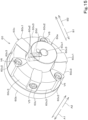
- FIG. 15 is a perspective view of the connector 60 as seen from the left rear.
- the connector 60 is a coupling to connect the drive shaft 91a and the input shaft 92a.
- the connector 60 extends between the drive shaft 91a and the input shaft 92a, and connects the drive shaft 91a and the input shaft 92a such that the drive shaft 91a and the input shaft 92a rotate together about the same axis.
- the connector 60 is, for example, a substantially cylindrical member extending in the axial direction of the drive shaft 91a and the input shaft 92a.
- the connector 60 is rotatable together with one of the drive shaft 91a and the input shaft 92a and is restricted from moving in the axial direction.
- the connector 60 is rotatable together with the other of the drive shaft 91a and the input shaft 92a and is not restricted from moving in the axial direction.
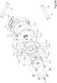
- FIG. 16 is an exploded perspective view showing the connector 60 as seen from the left rear.
- the connector 60 includes a first connector portion (clamping hub, boss portion) 60a to have attached thereto one of the drive shaft 91a and the input shaft 92a, a second connector portion (flange hub, flange portions) 60b to have attached thereto the other one of the drive shaft 91a and the input shaft 92a, and an elastic body 60c to connect the first connector portion 60a and the second connector portion 60b.
- the first connector portion 60a is rotatable together with one of the drive shaft 91a and the input shaft 92a and is restricted from moving in the axial direction.
- the second connector portion 60b is rotatable together with the other of the drive shaft 91a and the input shaft 92a and is not restricted in moving the axial direction.
- the first connector portion 60a has attached thereto a restrictor 60d to restrict (lock) the movement in the axial direction of one of the shafts.
- the second connector portion 60b has no restrictors 60d attached thereto, unlike the connector portion 60a.
- the first connector portion 60a is in the shape of a cylinder, and has, at a central portion thereof, a first insertion hole 60a1 to have the drive shaft 91a inserted therethrough.
- the first insertion hole 60a1 defines a splined bearing having internal splines which fit the external splines on the drive shaft 91a.
- the outer surface of the first connector portion 60a have first attaching hole(s) 60a2 and second attaching hole(s) 60a3.
- the first attaching hole 60a2 is a hole to attach the restrictor 60d thereto. As shown in FIGS. 15 and 16 , the first attaching hole 60a2 is a through-hole extending in a radial direction from the outer surface of the first connector portion 60a to the first insertion hole 60a1. The first attaching hole 60a2 is located in one of opposite end portions of the first connector portion 60a that is distant from the second connector portion 60b the other (in a rear portion of the first connector portion 60a in the present embodiment), and, when the first connector portion 60a is attached to the elastic body 60c, the first attaching hole 60a2 is located rearward of the elastic body 60c.
- the first connector portion 60a has a plurality of the first attaching holes 60a2 (two holes in the present embodiment).
- FIG. 17 is a cross-sectional view showing the electric motor 91, the support portion 65, the connector 60, and the hydraulic pump 92 as seen from the right side. As shown in FIG. 17 , the plurality of first attaching holes 60a2 are adjacent to each other in the axial direction (front-rear direction) of the drive shaft 91a and the input shaft 92a.
- the restrictor 60d is able to restrict the movement of the drive shaft 91a inserted in the first insertion hole 60a1.
- the restrictor 60d prevents the movement in the front-rear direction of the drive shaft 91a inserted in the first insertion hole 60a1.
- the restrictor 60d is a socket set screw.
- the restrictor 60d is screwed into the first insertion hole 60a1, and, when the distal portion of the restrictor 60d abuts the outer surface of the drive shaft 91a inserted in the first insertion hole 60a1, the restrictor 60d restricts the movement of the drive shaft 91a.
- the restrictor 60d is not limited to a socket set screw, and may be, for example, a bolt to be screwed into the first attaching hole 60a2, or may be a spring pin to be pressed into the first attaching hole 60a2. Further, the restrictor 60d need only be capable of restricting at least the movement in the axial direction of the drive shaft 91a, and may, for example, be a pin passing through the first attaching hole 60a2 and the drive shaft 91a.
- the restrictor 60d may be a ball lock mechanism provided on one of the first connector portion 60a and the drive shaft 91a instead of providing the first attaching hole 60a2 in the first connector portion 60a, and an existing technique can be used. In such a case, the other of the first connector portion 60a and the drive shaft 91a includes a recess with fits the ball lock mechanism or the like.
- the second attaching hole 60a3 is a hole to attach the elastic body 60c thereto. As shown in FIG. 16 , the second attaching hole 60a3 is a through-hole extending in a radial direction from the outer surface of the first connector portion 60a to the first insertion hole 60a1. The second attaching hole 60a3 is provided at one of the opposite end portions of the first connector portion 60a that is closer to the second connector portion 60b than the other (a front portion of the first connector portion 60a in the present embodiment). Specifically, the second attaching hole 60a3 is positioned such that the second attaching hole 60a3 overlaps the elastic body 60c in side view.
- the first connector portion 60a includes a plurality of the second attaching holes 60a3 (three holes in the present embodiment). The plurality of second attaching holes 60a3 are equally spaced from each other along the direction of rotation of the drive shaft 91a and the input shaft 92a.
- the second connector portion 60b is substantially in the form of a disc, and includes, at the central portion thereof, a second insertion hole 60b1 to have the input shaft 92a inserted therethrough.
- the second insertion hole 60b1 is a splined bearing having internal splines which fit the external splines on the input shaft 92a.
- the second connector portion 60b does not have attached thereto any member to restrict the movement in the axial direction of the shaft attached thereto, such as the restrictor 60d of the first connector portion 60a.
- the second connector portion 60b includes, at a radially outer portion thereof, third attaching hole(s) 60b2 to attach the elastic body 60c.
- Each third attaching hole 60b2 is a through-hole extending in the axial direction of the drive shaft 91a and of the input shaft 92a.
- the second connector portion 60b includes a plurality of the third attaching holes 60b2 (three holes in the present embodiment). The plurality of third attaching holes 60b2 are equally spaced from each other in the direction of rotation of the drive shaft 91a and the input shaft 92a.
- the plurality of third attaching holes 60b2 are positioned such that they do not coincide with the plurality of second attaching holes 60a3 in the direction of rotation of the drive shaft 91a and the input shaft 92a. In the present embodiment, the plurality of third attaching holes 60b2 are each located between adjacent second attaching holes 60a3.
- the elastic body 60c includes first connecting member(s) 60c1, second connecting member(s) 60c2, and elastic member(s) 60c3. Each first connecting member 60c1 is fixed to the first connector portion 60a.
- the first connecting member 60c1 is made of metal or the like.
- the elastic body 60c includes a plurality of the first connecting members 60c1 and, in the present embodiment, includes three first connecting members 60c1 corresponding to the number of second attaching holes 60a3.
- the first connecting members 60c1 are fixed to the first connector portion 60a via fastener(s) V5 such as bolt(s).
- Each first connecting member 60c1 includes hole(s) 60c 11 to have the fastener(s) V5 inserted therein.
- the first connecting members 60c1 are provided equally spaced from each other in the direction of rotation of the drive shaft 91a and of the input shaft 92a at the outer perimeter of the first connector portion 60a.
- Each second connecting member 60c2 is fixed to the second connector portion 60b.
- the second connecting member 60c2 is made of metal or the like.
- the elastic body 60c includes a plurality of the second connecting members 60c2 and, in the present embodiment, includes three second connecting members 60c2 corresponding to the number of third attaching holes 60a3.
- the second connecting members 60c2 are fixed to the second connector portion 60b via the fastener(s) V6 such as bolt(s).
- Each second connecting members 60c2 includes holes(s) 60c21 to have fastener(s) V6 inserted therein.
- the plurality of second connecting members 60c2 are equally spaced from each other in the direction of rotation of the drive shaft 91a and of the input shaft 92a at the outer perimeter of the second connector portion 60b.
- each elastic member 60c3 is fixed to the first connecting members 60c1 and to the second connecting members 60c2.
- each elastic member 60c3 is substantially in the shape of a sector in front view and rear view.
- each elastic member 60c3 is provided between a corresponding first connecting member 60c1 and a corresponding second connecting member 60c2. That is, the first connecting members 60c1, the second connecting members 60c2 and the elastic members 60c3 are arranged in the direction of rotation of the first drive shaft 91a and the input shaft 92a in the repeating order of the first connecting member 60c1, the second connecting member 60c2, and the elastic member 60c3.
- the elastic member 60c3 is fixed by being bonded to the first connecting member 60c1 and the second connecting member 60c2.
- the elastic member 60c3 is bonded at the contact surfaces with the first connecting member 60c1 and the second connecting member 60c2 using an adhesive.
- the contact surfaces of the first connecting member 60c1 and the elastic member 60c3, and the contact surfaces of the second connecting member 60c2 and the elastic member 60c3 are hatched.
- the first bracket (bracket) 61 is provided independently of the electric motor 91 and connects the electric motor 91 and the support portion 65.
- the first bracket 61 which is attached in advance to electric motor 91 together with the connector 60, is attached to the support portion 65.
- FIG. 18 is an exploded perspective view showing the electric motor 91, the connector 60, and the first bracket 61 as seen from the left front.
- the first bracket 61 includes a plate made of a thick steel sheet or the like.
- the first bracket 61 is substantially in the shape of a square in front view or rear view, and has, at the central portion thereof, a first socket hole (socket hole) 61a.
- the first socket hole 61a is for insertion of the drive shaft 91a, and has attached thereto a first spigot fitting portion (spigot fitting portion) 91b2 provided around the drive shaft 91a on a casing 91b of the electric motor 91.
- the first spigot fitting portion 91b2 projects toward the distal end of the drive shaft 91a from a first collar portion 91b1 provided at one of opposite end portions of the casing 91b of the electric motor 91 that is closer to the drive shaft 91a than the other.
- the inner diameter of the first socket hole 61a is smaller than the outer diameter of the connector 60, and the first bracket 61 is attached to the electric motor 91 before the connector 60 is connected to the drive shaft 91a.
- the first bracket 61 includes a first coupling portion 61A connected to the electric motor 91, and a first extension portion (extension portion) 61B connected to the support portion 65.
- the first coupling portion 61A is connected to the first collar portion 91b1, and has hole(s) 61A1 passing through the first coupling portion 61A in the axial direction of the first coupling portion 61A and configured to have fastener(s) V1 such as bolt(s) inserted therethrough.
- the first extension portion 61B is located outward of the first coupling portion 61A in the radial direction of the drive shaft 91a. That is, the first extension portion 61B projects outward in the radial direction of the drive shaft 91a relative to the electric motor 91.
- the first extension portion 61B includes first connected portion(s) (connected portion) 61B1 connected to the support portion 65.
- Each first connected portion 61B1 is a through-hole extending in the axial direction of the drive shaft 91a and configured to have a fastener V2 such as a bolt inserted therein, and the first bracket 61 and the support portion 65 are fastened via the fastener(s) V2.
- the first extension portion 61B has four first connected portions 61B1, which are located at respective corners of the first extension portion 61B.
- the first bracket 61 is attached to the electric motor 91 after fitting the first spigot fitting portion 91b2 and the first socket hole 61a with each other to position the axis of the drive shaft 91a and the center of the first socket hole 61a relative to each other.
- the second bracket (bracket) 62 is provided independently of the hydraulic pump 92 and connects the hydraulic pump 92 and the support portion 65.
- the second bracket 62 which is attached in advance to the hydraulic pump 92 together with the connector 60, is attached to the support portion 65.
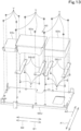
- FIG. 19 is an exploded perspective view showing the hydraulic pump 92 and the second bracket 62 as seen from the right rear.
- the second bracket 62 includes a plate made of a thick steel sheet or the like.
- the second bracket 62 is substantially in the form of a ring in front view and rear view, and has, at the central portion thereof, a second socket hole (socket hole) 62a.
- the second socket hole 62a is a hole to have the input shaft 92a inserted therethrough, and has attached thereto a second spigot fitting portion (spigot fitting portion) 92b2 provided around the input shaft 92a on a casing 92b of the hydraulic pump 92.
- the second spigot fitting portion 92b2 projects toward the distal portion of the input shaft 92a from a second collar portion 92b1 provided at one of the opposite end portions of the casing 92b of the hydraulic pump 92 that is closer to the input shaft 92a than the other.
- the second bracket 62 is attached to the hydraulic pump 92 before being attached to the support portion 65.
- the second bracket 62 includes a second coupling portion 62A connected to the hydraulic pump 92, and a second extension portion (extension portion) 62B connected to the support portion 65.
- the second coupling portion 62A is connected to the second collar portion 92b1, and has hole(s) 62A1 passing through the second coupling portion 62A in the axial direction of the input shaft 92a and configured to have fastener(s) V3 such as bolt(s) fastened.
- the two holes 62A1 are provided in the second coupling portion 62A, and are located above and below the input shaft 92a.
- the second extension portion 62B is located outward of the second coupling portion 62A in the radial direction of the input shaft 92a. That is, the second extension portion 62B projects outward in the radial direction of the input shaft 92a relative to the hydraulic pump 92.
- the second extension portion 62B includes second connected portion(s) (connected portion) 62B1 connected to the support portion 65.
- Each second connected portion 62B 1 is a through-hole extending in the axial direction of the input shaft 92a and configured to have a fastener V4 such as a bolt inserted therethrough, and the second bracket 62 and the support portion 65 are connected via the fastener(s) V4.
- three second connected portions 62B1 are provided in the second extension portion 62B.
- Two of the second connected portions 62B1 are provided at the upper portion of the second extension portion 62B, and the other one second connected portion 62B1 is provided at the lower portion of the second extension portion 62B.
- the second connected portion 62B1 at the lower portion of the second extension portion 62B is offset in the width direction from the input shaft 92a. With this, the operator can easily achieve access using a tool when attaching the fastener V4 to the second connected portion 62B1 at the lower portion of the second extension portion 62B.
- the second bracket 62 is attached to the hydraulic pump 92 after fitting the second spigot fitting portion 92b2 and the second socket hole 62a with each other to position of the axis of the input shaft 92a and the center of the second socket hole 62a relative to each other.
- the support portion 65 is a base to support the electric motor 91 and the hydraulic pump 92 above the swivel base 2 at one side of the battery unit 90.
- the support portion 65 is independent of the support body and supports the electric motor 91 and the hydraulic pump 92 above the swivel base 2 at the rear portion of the swivel base 2.
- the support portion 65 under the conditions in which the electric motor 91 is attached to the support portion 65 via the first bracket 61 and the hydraulic pump 92 is attached to the support portion 65 via the second bracket 62, the support portion 65 also functions as a housing to surround the connector 60 at a position radially outward of the connector.
- the support portion 65 functions also as a housing, but a housing to surround the connector 60 at a position radially outward of the connector 60 may be provided independently of the support portion 65.
- the support portion 65 connects the electric motor 91 and the hydraulic pump 92 and supports the electric motor 91 and the hydraulic pump 92 such that the electric motor 91 and the hydraulic pump 92 are arranged in the front-rear direction.
- FIG. 20 is a right-rear perspective view showing the support portion 65.
- FIG. 21 is an exploded perspective view showing the manner in which the first bracket 61 and the like are attached to the support portion 65.
- FIG. 22 is an exploded perspective view showing the manner in which the second bracket 62 and the like are attached to the support portion 65.
- the support portion 65 includes a first upright plate 66, a second upright plate 67, a curved portion 68, and a base portion 69.
- the first upright plate 66 includes a plate made of a thick steel sheet or the like.
- the first upright plate 66 is provided upright such that the sheet surfaces face in the axial direction of the drive shaft 91a and the input shaft 92a (front-rear direction).
- the first upright plate 66 is substantially in the shape of a square in front view and rear view, and corresponds to the first bracket 61.
- the central portion of the first upright plate 66 includes a first opening portion 66a to have the connector 60 inserted therein. That is, the inner diameter of the first opening portion 66a is greater than the outer diameter of the connector 60.
- the first upright plate 66 has, at a peripheral portion thereof, hole(s) 66b to have fastened thereto fastener(s) V2 such as bolt(s) inserted in the first connected portion(s) 61B1.
- first upright plate 66 has, at a peripheral portion thereof, cutout(s) 66c and hole(s) 66d to avoid contact with the fastener(s) V1 connecting the electric motor 91 and the first bracket 61.
- the second upright plate 67 includes a plate made of a thick steel sheet or the like.
- the second upright plate 67 is provided upright such that the sheet surfaces face in the axial direction of the drive shaft 91a and the input shaft 92a (front-rear direction).
- the second upright plate 67 is spaced from the first upright plate 66 and faces the first upright plate 66 in the axial direction of the drive shaft 91a and the input shaft 92a (front-rear direction).
- the upper portion of the second upright plate 67 is in the form of a semicircle, and the lower portion of the second upright plate 67 is substantially in the form of a rectangle in front view or rear view, and the second upright plate 67 corresponds to the second bracket 62.
- the second upright plate 67 has, at a central portion thereof, a second opening portion 67a corresponding to the first opening portion 66a.
- the second upright plate 67 has, at a peripheral portion thereof, hole(s) 67b to have fastened thereto fastener(s) V4 such as bolt(s) inserted in the second connected portion(s) 62B1.
- the curved portion 68 is a component provided between the first upright plate 66 and the second upright plate 67, and connecting the first upright plate 66 and the second upright plate 67.
- the curved portion 68 includes a plate made of a thick steel sheet or the like, and is in the form of a reverse U letter protruding upward in front view or rear view.
- One of opposite side portions (left end portion) of the curved portion 68 extends upward from the upper surface of the base portion 69, an intermediate portion of the curved portion 68 curves along the outer perimeter of the connector 60, and the other of the opposite side portions (right portion) of the curved portion 68 reaches the upper surface of the base portion 69.
- the base portion 69 includes a plate made of a thick steel sheet or the like, and is positioned such that the plate surfaces face in the up-down direction.
- the base portion 69 supports the first upright plate 66, the second upright plate 67, and the curved portion 68 above the swivel base 2.
- the base portion 69 includes a central portion 69a provided with the first upright plate 66, the second upright plate 67, and the curved portion 68, and a pair of extension portions 69b and 69c extending from the central portion 69a.
- the central portion 69a is substantially in the shape of a rectangle elongated in the width direction, and opposite side portions in the width direction of the central portion 69a protrude outward relative to the electric motor 91 and the hydraulic pump 92 along the width direction.
- the pair of extension portions 69b and 69c include a first extension portion 69b extending rearward from the rear edge of the central portion 69a, and a second extension portion 69c extending forward from the front edge of the central portion 69a.
- the first extension portion 69b defines a rear portion of the base portion 69, and is substantially in the shape of a trapezoid in plan view.
- the opposite end portions in the width direction of the first extension portion 69b protrude outward relative to the electric motor 91 and the hydraulic pump 92 in the width direction.
- the rear portion of the first extension portion 69b includes an inclined portion 69b1 extending diagonally from front to rear in the direction from the other of the opposite side portions (right portion) to the one of the opposite side portions (left portion).
- the inclined portion 69b1 is in the shape that conforms to the contour of the right rear portion of the outside cover 80.
- the first extension portion 69b includes an opening 69b2 passing through the first extension portion 69b in the up-down direction.
- the second extension portion 69c is a component defining a front end portion of the base portion 69, and the opposite side portions in the width direction of the second extension portion 69c protrude outward relative to the electric motor 91 and the hydraulic pump 92 in the width direction.
- the second extension portion 69c includes a cutout 69c1 at a front end portion thereof. The cutout 69c1 is provided to avoid contact with protrusions provided on the hydraulic pump 92 such as port(s).
- the support portion 65 is attached to the swivel base 2 via a plurality of mounting devices 70.
- the plurality of mounting devices 70 are located outward of the electric motor 91, the hydraulic pump 92, and the support portion 65 in the width direction in plan view,.
- the plurality of mounting devices 70 are a vibration-proof structure including elastically deformable elastic members and/or the like. As shown in FIG. 14 , there are four such mounting devices 70. As shown in FIG. 7 , the plurality of mounting devices 70 are attached to fixed brackets 41 and 42 attached to the swivel base 2. Note that the number of the plurality of mounting devices 70 is not limited to four, and may be three, or may be five. In the present embodiment, the plurality of mounting devices 70 include a pair of rear mounting devices 70a and a pair of front mounting devices 70b.
- the pair of rear portion mounting devices 70a are arranged in the width direction at the rear end portion of the first extension portion 69b.
- the pair of rear portion mounting devices 70a support one of the opposite sides in the width direction (left side) and the other of the opposite sides (right side) of the rear end portion of the first extension portion 69b.
- the pair of rear portion mounting devices 70a are, in plan view, located outward of the electric motor 91, the hydraulic pump 92 and the support portion 65.
- the center of a nut N fastening a corresponding rear portion mounting device 70a and the first extension portion 69b is located outward of the electric motor 91, the hydraulic pump 92 and the support portion 65 in the width direction.
- the pair of rear portion mounting devices 70a are displaced from each other in the front-rear direction.
- the pair of front portion mounting devices 70b are arranged in the width direction at the front end portion of the second extension portion 69c.
- the pair of front portion mounting devices 70b support one of the opposite sides in the width direction (, left side) and the other of the opposite sides (right side) of the front end portion of the second extension portion 69c.
- the pair of front portion mounting devices 70b are, in plan view, located outward of the electric motor 91, the hydraulic pump 92 and the support portion 65 in the width direction.
- the center of a nut N fastening a corresponding front portion mounting devices 70b and the second extension portion 69c is located outward of the electric motor 91, the hydraulic pump 92 and the support portion 65 in the width direction.
- the pair of front portion mounting devices 70b are arranged such that they coincide with each other in position in the front-rear direction.
- the support portion 65 is provided with dowel pin(s) 66e and 67c to be fitted in the first bracket 61 and/or the second bracket 62.
- the first upright plate 66 is provided with dowel pin(s) (first dowel pin) 66e directed in the axial direction of the drive shaft 91a.
- a plurality of the first dowel pins 66e are provided on the first upright plate 66 and, in the present embodiment, the first upright plate 66 is provided with two first dowel pins 66e.
- FIG. 23 is a rear view of the support portion 65 showing the positions of the first dowel pins 66e.
- the pair of first dowel pins 66e are provided at a peripheral portion of the first upright plate 66, and is positioned such that a straight line L1 connecting the axes of the first dowel pins 66e passes through the axis of the drive shaft 91a.
- one of the first dowel pins 66e is provided at a lower portion of one of the opposite sides in the width direction (left side) of the first extension portion 61B, and the other first dowel pin 66e is provided at an upper portion of the other of the opposite sides (right side) of the first extension portion 61B.
- the first bracket 61 includes holes (first fitting holes) 61B2 in which the first dowel pins 66e are fitted.
- the first fitting holes 61B2 are through-holes extending in the axial direction of the drive shaft 91a, and are provided at positions corresponding to the pair of first dowel pins 66e.
- the second upright plate 67 is provided with dowel pin(s) (second dowel pins) 67c directed in the axial direction of the input shaft 92a.
- a plurality of the second dowel pins 67c are provided on the second upright plate 67 and, in the present embodiment, the second upright plate 67 is provided with two first dowel pins 67c.
- FIG. 24 is a front view of the support portion 65 showing the positions of the second dowel pins 67c.
- the pair of second dowel pins 67c are provided at a peripheral portion of the second upright plate 67, and are arranged such that a straight line L2 connecting the axes of the second dowel pins 67c is displaced from the axis of the input shaft 92a.
- one of the second dowel pins 67c is provided at the other of the opposite sides in the width direction (right side) of the upper portion of the second extension portion 62B, and the other second dowel pin 67c is provided at the other of the opposite sides (right side) of the lower portion of the second extension portion 62B. That is, the pair of second dowel pins 67c are located rightward of a perpendicular line Z passing through the axis of the input shaft 92a.
- the second bracket 62 includes holes (second fitting holes) 62B2 to have the second dowel pins 67c fitted therein.
- the second fitting holes 62B2 are through-holes extending in the axial direction of the input shaft 92a, and are provided at positions corresponding to the pair of second dowel pins 67c.
- At least two or more of the electric motor 91, the first bracket 61, the support portion 65, the second bracket 62, and the hydraulic pump 92 are provided with a portion-for-attachment 71 to attach a hoisting attachment 75 thereto.
- such portions-for-attachment 71 are provided on the electric motor 91, the support portion 65, and the second bracket 62.
- the hoisting attachment 75 is an eyebolt, and is detachably attached to the portion-for-attachment 71. Note that the holes in the portions-for-attachment 71 to each of which the hoisting attachment 75 is fastened are the same, and therefore the same hoisting attachment 75 can be used.
- a pair of the portions-for-attachment 71 are provided on the electric motor 91.
- the pair of portions-for-attachment 71 are provided at an upper portion at one of opposite ends in the axial direction of the drive shaft 91a (left end) of the casing 91b of the electric motor 91 and at an upper portion at the other of the opposite ends (left end) of the casing 91b of the electric motor 91.
- the support portion 65 is provided with the portion-for-attachment 71 (second portion-for-attachment 71B) to attach the hoisting attachment 75 (second hoisting attachment 75B).
- the second portion-for-attachment 71B is configured to connect the upper portion of the first upright plate 66 and the upper portion of the curved portion 68.
- the second bracket 62 is provided with the portion-for-attachment 71 (first portion-for-attachment 71A) to attach the hoisting attachment 75 (first hoisting attachment 75A).
- the first portion-for-attachment 71A is provided at the upper portion of the second bracket 62.
- portions-for-attachment 71 are provided on the electric motor 91, the support portion 65 and the second bracket 62. However, it is only necessary that at least two of the electric motor 91, the first bracket 61, the support portion 65, the second bracket 62 and the hydraulic pump 92 be provided with the portions-for-attachment 71 to attach the hoisting attachment 75, and the portions-for-attachment 71 may be provided on the first bracket 61 and/or the hydraulic pump 92.
- the operator positions the first socket hole 61a and the first spigot fitting portion 91b2 relative to each other, and attaches the first spigot fitting portion 91b2 to the first socket hole 61a.
- the operator attaches the connector 60 to the drive shaft 91a of the electric motor 91 to which the first bracket 61 is attached. Specifically, the operator inserts the drive shaft 91a into the first insertion hole 60a1 in the first connector portion 60a of the connector 60, and causes the drive shaft 91a (which is a splined shaft) and the first insertion hole 60a1 (which is a splined bearing) to fit with each other in the direction of rotation of the drive shaft 91a. The operator screws the restrictors 60d (socket set screws) into the first attaching holes 60a2, and causes the distal portion of each restrictor 60d to abut the outer surface of the drive shaft 91a.
- the operator can attach the connector 60 to the drive shaft 91a such that the connector 60 is rotatable together with the drive shaft 91a and is restricted from moving in the axial direction.
- the step of attaching the first bracket 61 and the connector 60 to the electric motor 91 may be referred to a "first step" of the process to attach the electric motor 91 to the support portion 65.
- the structure that includes the electric motor 91, the first bracket 61 and the connector 60 assembled in the first step may be referred to as a "first assembly".
- the step of attaching the connector 60 to one of the drive shaft 91a and the input shaft 92a such that the connector 60 is rotatable together with the one of the drive shaft 91a and the input shaft 92a and restricted from moving in the axial direction may be referred to as a "first step" of the process to attach the connector 60 to the electric motor 91 and the hydraulic pump 92.
- the operator attaches the hoisting attachments 75 to the pair of portions-for-attachment 71 of the electric motor 91.
- the operator attaches the hook of a crane provided in a work site such as a factory or the like to each hoisting attachment 75, and lifts up (hists up) the first assembly.
- the operator inserts the connector 60 in the first opening portion 66a and positions the first dowel pins 66e and the first fitting holes 61B2 relative to each other.
- the pair of first dowel pins 66e are positioned such that the straight line L1 connecting the axes of the first dowel pins 66e passes through the axis of the drive shaft 91a, by swinging the first assembly about the drive shaft 91a, the operator can easily position the first dowel pins 66e and the first fitting holes 61B2 relative to each other.
- the operator After fitting the first dowel pins 66e into the first fitting holes 61B2, the operator inserts the fasteners V2 into the first connected portions 61B1, to attach the first bracket 61 to the support portion 65.
- the step of attaching the first assembly to the support portion 65 may be referred to as a "second step" of the process to attach the electric motor 91 to the support portion 65.
- the operator positions the second socket hole 62a and the second spigot fitting portion 92b2 relative to each other, and attaches the second spigot fitting portion 92b2 to the second socket hole 62a.
- the operator fastens the fasteners V3 to the holes 62A1 via the holes in the second collar portion 92b1, to attach the second bracket 62 to the hydraulic pump 92.
- the step of attaching the second bracket 62 to the hydraulic pump 92 may be referred to as a "first step" of the process to attach the hydraulic pump 92 to the support portion 65.
- the structure that includes the hydraulic pump 92 and the second bracket 62 assembled in the first step may be referred to as a "second assembly”.
- the operator while positioning the second dowel pins 67c and the second fitting holes 62B2 relative to each other, inserts the input shaft 92a into the second insertion hole 60b1 of the second connector portion 60b, and causes the input shaft 92a (which is a splined shaft) and the second insertion hole 60b1 (which is a splined bearing) to fit with each other in the direction of rotation of the input shaft 92a.
- the operator can attach the input shaft 92a to the connector 60 such that the connector 60 is rotatable together with the input shaft 92a and is not restricted from moving in the axial direction.
- the pair of second dowel pins 67c are positioned such that the straight line L2 connecting the axes of the second dowel pins 67c is displaced from the axis of the input shaft 92a, in the case where the operator performs work from one of opposite sides in the width direction (from left side), the operator can easily position the input shaft 92a and the second connector portion 60b relative to each other, and position the second dowel pins 67c and the second fitting holes 62B2 relative to each other, without being prevented by the second dowel pins 67c from checking the positions of the input shaft 92a and the second connector portion 60b.
- the step of attaching the other of the drive shaft 91a and the input shaft 92a to the connector 60 such that the other of the drive shaft 91a and the input shaft 92a is rotatable together with the connector 60 and is not restricted from moving in the axial direction relative to the connector 60 may be referred to as a "second step" of the process to attach the connector 60 to the electric motor 91 and the hydraulic pump 92.
- the connector 60 is attached to the electric motor 91 or the hydraulic pump 92 that has one of the shafts (the electric motor 91 in the present embodiment) and attached to the support portion 65, by moving the electric motor 91 or the hydraulic pump 92 that has the other of the shafts (the hydraulic pump 92 in the present embodiment) in the axial direction, it is possible to detach the hydraulic pump 92 from the connector 60.
- the operator may attach the first hoisting attachment 75A to the first portion-for-attachment 71A.
- the operator can attach the hook of a crane to the first hoisting attachment 75A and lift up (hoist up) the second assembly.
- the operator inserts the fasteners V4 into the second connected portions 62B1 to attach the second bracket 62 to the support portion 65.
- the step of attaching the second assembly to the support portion 65 may be referred to as a "second step" of the process to attach the hydraulic pump 92 to the support portion 65.
- the structure including the electric motor 91, the hydraulic pump92, the connector 60, the first bracket 61, the second bracket 62 and the support portion 65 may be referred to as a "third assembly".
- FIG. 25 is a right rear perspective view showing the manner in which the third assembly is attached.
- the operates moves the third assembly toward the fixed brackets 41 and 42 on the swivel base 2 using the crane and, as shown in FIG. 25 , positions the plurality of mounting devices 70 and the support portion 65 relative to each other.
- the operator fastens the pair of rear portion mounting devices 70a and the first extension portion 69b and fastens the pair of front portion mounting devices 70b and the second extension portion 69c, using nuts N.
- a the support portion 65 includes the dowel pins (first dowel pins) 66e and the dowel pins (second dowel pins) 67c, and the first bracket 61 and the second bracket 62 are positioned relative to the support portion 65.
- the configuration in which, instead of the dowel pins 66e and 67c, some other members are used to position the first bracket 61 and the second bracket 62 relative to the support portion 65 may be used.
- FIG. 26 is an exploded perspective view of the electric motor 91, the connector 60 and the first bracket 61 according to a variation as seen from the left front.
- FIG. 27 is an exploded perspective view of the hydraulic pump 92 and the second bracket 62 according to the variation as seen from the right rear.
- FIG. 28 is a right rear perspective view showing the manner in which the first assembly and the second assembly are attached to the support portion 65 according to the variation.
- the first bracket 61 includes a third spigot fitting portion (spigot fitting portion) 61C.
- the third spigot fitting portion 61C projects from the first coupling portion 61A toward the distal end of the drive shaft 91a, i.e., projects away from the electric motor 91 (projects forward).
- the third spigot fitting portion 61C is a rib in the form of a circular ring, and the outer diameter of the third spigot fitting portion 61C is substantially the same as the inner diameter of the first opening portion 66a.
- the third spigot fitting portion 61C is attached to the first opening portion 66a.
- the inner diameter of the third spigot fitting portion 61C is greater than the outer diameter of the connector 60.
- the third spigot fitting portion 61C may house a portion of the connector 60 therein. In such a case, since it is possible to cover the space between the connector 60 and the drive shaft 91a with the third spigot fitting portion 61C, it is possible to improve the dust resistance of the space between the connector 60 and the drive shaft 91a.
- the lower one of the first connected portions 61B1 provided on the first extension portion 61B is located closer to the hole 61A1 at the center in the up-down direction than to the lower hole 61A1.
- one of the first connected portions 61B1 provided on the first extension portion 61B is displaced outward along the width direction from a corresponding hole 61A1.
- one of the lower first connected portions 61B1 that is located at one of opposite sides in the width direction (right side) is displaced outward along the width direction (rightward) from the corresponding hole 61A1.
- the operator can easily achieve the access using a tool when attaching the fasteners V2 to the first connected portions 61B1.
- the second bracket 62 of the variation includes a fourth spigot fitting portion (spigot fitting portion) 62C.
- the fourth spigot fitting portion 62C projects from the second coupling portion 62A toward the distal end of the input shaft 92a, i.e., projects away from the hydraulic pump 92 (projects rearward).
- the fourth spigot fitting portion 62C is in the shape of a cylinder.
- the outer diameter of the fourth spigot fitting portion 62C is substantially the same as the inner diameter of the second opening portion 67a and, as shown in FIG. 28 , the fourth spigot fitting portion 62C is attached to the second opening portion 67a.
- a swivel working machine 1 as has been described includes a swivel base 2, a battery unit 90, an electric motor 91 to rotate a drive shaft 91a using electricity outputted from the battery unit 90, a hydraulic pump 92 including an input shaft 92a to receive input of power from the drive shaft 91a and configured to be driven by power inputted into the input shaft 92a from the drive shaft 91a to deliver hydraulic fluid, a connector 60 to connect the drive shaft 91a and the input shaft 92a, a support portion 65 to support the electric motor 91 and the hydraulic pump 92 on or above the swivel base 2, and a bracket (first bracket) 61 provided independently of the electric motor 91 to connect the electric motor 91 and the support portion 65, wherein a structure (first assembly) in which the connector 60 and the first bracket 61 are attached to the support portion 65 is attached to the support portion 65 via the first bracket 61.
- the electric motor 91 includes a spigot fitting portion (first spigot fitting portion) 91b2 around the drive shaft 91a, and the first bracket 61 includes a socket hole (first socket hole) 61a to have the spigot fitting portion 91b2 attached thereto.
- the outer diameter of the connector 60 is greater than the inner diameter of the first socket hole 61a.
- the support portion 65 is a housing to, under the conditions in which the electric motor 91 is attached to the support portion 65 via the first bracket 61, surround the connector 60 at a position radially outward of the connector 60.
- the support portion 65 is able to support the electric motor 91 and cover the connector 60.
- the first bracket 61 and the connector 60 are attached in advance to the electric motor 91 and then such first bracket 61, connector 60 and electric motor 91 are attached to the support portion 65, it is possible to easily perform positioning with respect to the drive shaft 91a as compared to cases where the electric motor 91 is attached to the support portion 65 and then the connector 60 is attached.
- the first bracket 61 includes an extension portion (first extension portion) 61B extending outward in a radial direction of the drive shaft 91a relative to the electric motor 91, and the first extension portion 61B includes a connected portion (first connected portion) 61B1 connected to the support portion 65.
- the first connected portion 61B1 is a hole to have a fastener V2 inserted therethrough, and the first bracket 61 and the support portion 65 are connected by the fastener V2.
- the first bracket 61 it is possible to easily and reliably attach the first bracket 61 to the support portion 65. Since the first extension portion 61B extends outward in the radial direction of the drive shaft 91a relative to the electric motor 91, it is possible to ensure a sufficient area in which a tool is operated to attach the fastener V2.
- the support portion 65 is provided with a dowel pin (first dowel pin) 66e directed in the axial direction of the drive shaft 91a, and the first bracket 61 includes a hole (first fitting hole) 61a to have the first dowel pin 66e fitted therein.
- the first bracket 61 is provided with a portion-for-attachment 71 to attach a hoisting attachment 75 thereto.
- a method of assembling a swivel working machine 1 is a method of assembling a swivel working machine 1 including an electric motor 91 to rotate a drive shaft 91a, a hydraulic pump 92 including an input shaft 92a to receive input of power from the drive shaft 91a and configured to be driven by power inputted into the input shaft 92a from the drive shaft 91a, a connector 60 to connect the drive shaft 91a and the input shaft 92a, a support portion 65 to support the electric motor 91 and the hydraulic pump 92, and a first bracket 61 provided independently of the electric motor 91 to connect the electric motor 91 and the support portion 65, the method including a first step including attaching the first bracket 61 and the connector 60 to the electric motor 91, and a second step including attaching the first bracket 61, the connector 60, and the electric motor 91 assembled in the first step to the support portion 65.
- a swivel working machine 1 as has been described includes a swivel base 2, a battery unit 90, an electric motor 91 to rotate a drive shaft 91a to rotate using electricity outputted from the battery unit 90, a hydraulic pump 92 including an input shaft 92a to receive input of power from the drive shaft 91a and configured to be driven by power inputted into the input shaft 92a from the drive shaft 91a to deliver hydraulic fluid, a support portion 65 to support the electric motor 91 and the hydraulic pump 92 on or above the swivel base 2, and a bracket (second bracket) 62 provided independently of the hydraulic pump 92 to connect the hydraulic pump 92 and the support portion 65, wherein a structure (second assembly) in which the second bracket 62 is attached to the hydraulic pump 92 is attached to the support portion 65 via the second bracket 62.
- the second bracket 62 includes an extension portion (second extension portion) 62B extending outward in a radial direction of the input shaft 92a relative to the hydraulic pump 92, and the second extension portion 62B includes a connected portion (second connected portion) 62B1 connected to the support portion 65.
- the second connected portion 62B1 is a hole to have a fastener V4 inserted therethrough, and the second bracket 62 and the support portion 65 are connected by the fastener V4.
- the support portion 65 is provided with a dowel pin (second dowel pin) 67c directed in the axial direction of the input shaft 92a, and the second bracket 62 includes a hole (second fitting hole) 62B2 to have the second dowel pin 67c fitted therein.
- the second bracket 62 is provided with a first portion-for-attachment 71A to attach a first hoisting attachment 75A thereto.
- the support portion 65 is provided with a second portion-for-attachment 71B to attach a second hoisting attachment 75B thereto.
- the hydraulic pump 92 includes a spigot fitting portion (second spigot fitting portion) 92b2 around the input shaft 92a, and the second bracket 62 includes a socket hole (second socket hole) 62a to attach the spigot fitting portion 91b2 thereto.
- the swivel working machine 1 includes a connector 60 to connect the drive shaft 91a and the input shaft 92a, the hydraulic pump 92 is attached to the support portion 65 via the second bracket 62, and the support portion 65 is a housing to, under the conditions in which the connector 60 is attached to the input shaft 92a, surround the connector 60 at a position radially outward of the connector 60.
- the support portion 65 is able to support the hydraulic pump 92 and cover the connector 60.
- the support portion 65 is able to support the hydraulic pump 92 and cover the connector 60.
- a method of assembling a swivel working machine 1 is a method of assembling a swivel working machine 1 including an electric motor 91 to rotate a drive shaft 91a, a hydraulic pump 92 including an input shaft 92a to receive input of power from the drive shaft 91a and configured to be driven by power inputted into the input shaft 92a from the drive shaft 91a to deliver hydraulic fluid, a support portion 65 to support the electric motor 91 and the hydraulic pump 92, and a second bracket 62 provided independently of the hydraulic pump 92 to connect the hydraulic pump 92 and the support portion 65, the method including a first step including attaching the second bracket 62 to the hydraulic pump 92, and a second step including attaching the second bracket 62 and the hydraulic pump 92 assembled in the first step to the support portion 65.
- a swivel working machine 1 as has been described includes a swivel base 2, a battery unit 90, a support body 50 to support the battery unit 90 on or above the swivel base 2, an electric motor 91 to be driven by electricity outputted from the battery unit 90, a hydraulic pump 92 to be driven by the electric motor 91 to deliver hydraulic fluid, and a support portion 65 to support the electric motor 91 and the hydraulic pump 92 on or above the swivel base 2, wherein the support portion 65 is separate from the support body 50 and is attached to the swivel base 2 via a plurality of mounting devices 70.
- the support portion 65 supports the electric motor 91 and the hydraulic pump 92 independently of the battery unit 90, it is possible to eliminate or reduce the likelihood that the vibrations generated by driving of the electric motor 91 and the pulsations of the hydraulic pump 92 will be directly transmitted to the battery unit 90. Furthermore, since the assembly of the battery unit 90 and the assembly of the electric motor 91 and the hydraulic pump 92 are structured separately from each other, it is possible to achieve easy mounting on the swivel base 2. It is also possible to eliminate or reduce the likelihood that the vibrations generated by driving of the electric motor 91 and the pulsations of the hydraulic pump 92 will be transmitted to the battery unit 90 via the support portion 65 and the swivel base 2. With this, it is possible to eliminate or reduce the likelihood that the battery unit 90 will resonate due to the vibrations and pulsations, the vibrations and the like will be amplified, and noise will be generated
- the support body 50 is fixed to the swivel base 2.
- the battery unit 90 placed on the support body 50 is fixed to the swivel base 2, if vibrations are transmitted from the swivel base 2, the battery unit 90 does not vibrate independently of the swivel base 2 but vibrates together with the swivel base 2.
- the battery unit 90 will resonate due to the vibrations and pulsations, the vibrations and the like will be amplified, and noise will be generated
- the swivel working machine 1 further includes a stabilizer portion (lower upright portion) 57 provided upright at an upper portion of the support body 50 and attached to at least one of opposite sides of the battery unit 90.
- the support portion 65 supports the electric motor 91 and the hydraulic pump 92 which are arranged in a front-rear direction, and under the conditions in which the electric motor 91 and the hydraulic pump 92 are attached to the support portion 65, the plurality of mounting devices 70 are each located outward of the electric motor 91, the hydraulic pump 92 and the support portion 65 in plan view.
- the plurality of mounting devices 70 are able to prevent or reduce vibrations in the width direction, and more suitably support the electric motor 91, the hydraulic pump 92 and the support portion 65. Furthermore, when attaching the plurality of mounting devices 70 to the support portion 65, it is possible to more easily achieve assess using a tool.
- the battery unit 90 is located at a widthwise central portion of a rear portion of the swivel base 2, and the electric motor 91 and the hydraulic pump 92 are provided at one side of the battery unit 90 via the support portion 65.
- the swivel working machine 1 further includes a first bracket 61 provided independently of the electric motor 91 to connect the electric motor 91 and the support portion 65, and a second bracket 62 provided independently of the hydraulic pump 92 to connect the hydraulic pump 92 and the support portion 65.
- At least two of the electric motor 91, the first bracket 61, the support portion 65, the second bracket 62 and the hydraulic pump 92 are provided with a portion-for-attachment 71 to attach a hoisting attachments 75 thereto, the portion-for-attachment 71 being configured such that attaching the hoisting attachment 75 to the portion-for-attachment 71 allows a connected structure to be hoisted, the connection structure being a structure in which the electric motor 91 is connected to the support portion 65 via the first bracket 61 and the hydraulic pump 92 is connected to the support portion 65 via the second bracket 62.
- An electric working machine 1 as has been described includes a machine body (swivel base) 2, a support body 50 provided on the swivel base 2, a battery unit 90 placed on the support body 50, and an electric motor 91 to be driven by electricity outputted from the battery unit 90, wherein the support body 50 includes a plurality of long plate members 52 for placement of an outer peripheral portion of a bottom of the battery unit 90, and surfaces for placement of the battery unit 90 of the long plate members 52 are smoothened by machining.
- the portion of the support body 50 that is other than the surfaces for placement of the plate members 52 is not subjected to machining.
- the support body 50 includes a frame member 51 to connect the plurality of plate members 52, and the frame member 51 is fixed by welding to lower surfaces and/or side surfaces of the plate members 52.
- the plurality of plate members 52 are spaced from each other and fixed to the frame member 51.
- the plate members 52 subjected to machining after fixed to the frame member 51 by welding.
- the plurality of plate members 52 include a first plate portion 52a for placement of a front edge portion of the battery unit 90, a second plate portion 52b for placement of a rear edge portion of the battery unit 90, a third plate portion 52c for placement of one of opposite sides in the width direction of the battery unit 90, and a fourth plate portion 52d for placement of the other of the opposite sides in the width direction of the battery unit 90.
- the support body 50 includes a long first connector plate 53 to connect a widthwise central portion of the first plate portion 52a and a widthwise central portion of the second plate portion 52b.
- the support body 50 includes a second connector plate 54 passing through a center of an opening 51E at a central portion of the frame member 51 and extending from one of opposite ends in the width direction of the frame member 51 to the other of the opposite ends of the frame member 51, and the first connector plate 53 and the second connector plate 54 are perpendicular to each other.
- the battery unit 90 includes a plurality of batteries 90a, the plurality of batteries 90a are arranged adjacent to each other in the width direction, the first plate portion 52a has placed thereon front edge portions of the plurality of batteries 90a, the second plate portion 52b has placed thereon rear edge portions of the plurality of batteries 90a, the third plate portion 52c has placed thereon a first edge portion of one of the batteries 90a that is located at one of opposite ends in the width direction, and the fourth plate portion 52d has placed thereon a second edge portion of another of the batteries 90a that is located at the other of the opposite ends in the width direction.
- the battery unit 90 includes a plurality of batteries 90a, the first connector plate 53 has placed thereon two adjacent ones of the batteries 90a, and has a vent hole 53a between the two adjacent ones of the batteries 90a.
- the support body 50 includes a retainer 55 provided on the first plate portion 52a or the second plate portion 52b to fix the battery unit 90.
- the retainer 55 is attached such that the retainer 55 is adjustable in the front-rear direction.
- the electric working machine 1 includes a hydraulic device M provided on the swivel base 2 and a hydraulic pump 92 to be driven by the electric motor 91 to deliver hydraulic fluid to actuate the hydraulic device M.
- An electric working machine 1 includes an machine body (swivel base) 2, a battery unit 90, an electric motor 91 to rotate a drive shaft 91a using electricity outputted from the battery unit 90, a hydraulic pump 92 including an input shaft 92a to receive input of power from the drive shaft 91a and configured to be driven by power inputted into the input shaft 92a from the drive shaft 91a to deliver hydraulic fluid, a connector 60 to connect the drive shaft 91a and the input shaft 92a, and a support portion 65 to support the electric motor 91 and the hydraulic pump 92 on or above the swivel base 2, wherein the connector 60 is rotatable together with one of the drive shaft 91a and the input shaft 92a and restricted from moving an axial direction, and is rotatable together with the other of the drive shaft 91a and the input shaft 92a and not restricted from moving in the axial direction.
- the electric motor 91 and the hydraulic pump 92 are supported by the support portion 65, and the connector 60 restricts the one of the shafts from moving in the axial direction.
- the step of restricting the movement in the axial direction of the other of the shafts using the connector 60 is omitted, it is possible to maintain the relative positions in the axial direction of the connector 60 and the other of the shafts.
- the connector 60 includes a first connector portion 60a to have attached thereto one of the shafts, a second connector portion 60b to have attached thereto the other of the shafts, and an elastic body 60c to connect the first connector portion 60a and the second connector portion 60b.
- the elastic body 60c includes a first connecting member 60c1 fixed to the first connector portion 60a, a second connecting member 60c2 fixed to the second connector portion 60b, and an elastic member 60c3 fixed to the first connecting member 60c1 and the second connecting member 60c2.
- the elastic member 60c3 is fixed by being bonded to the first connecting member 60c1 and the second connecting member 60c2.
- the drive shaft 91a and the input shaft 92a are splined shafts, and the first connector portion 60a and the second connector portion 60b include splined bearings to fit with the spline shafts.
- the first connector portion 60a is configured to have attached thereto a restrictor 60d to restrict movement of the one of the shafts in the axial direction.
- the support portion 65 is a housing to, under the conditions in which the electric motor 91 is attached to the support portion 65, surround the connector 60 at a position radially outward of the connector 60.
- the swivel working machine 1 includes a housing 65 to, under the conditions in which the electric motor 91 and the hydraulic pump 92 are attached to the support portion 65, surround the connector 60 at a position radially outward of the connector 60, and under the conditions in which the connector 60 is attached to the electric motor 91 or the hydraulic pump 92 that has the one of the shafts and attached to the support portion 65, the electric motor 91 or the hydraulic pump 92 that has the other of the shafts is detachable from the connector 60 by moving it in the axial direction of the other of the shafts.
- the housing 65 it is possible, using the housing 65, to eliminate to reduce the likelihood that the connector 60 rotated by the rotating shaft will come into contact with the surrounding devices. Since it is possible to omit the step of restricting the movement in the axial direction of the other of the shafts or the step of removing the restriction, it is possible to eliminate or reduce the likelihood that the hydraulic pump 92 will not be easily detachable and attachable due to a support portion 65 which is a housing.
- a method of assembling an electric working machine 1 is a method of assembling an electric working machine 1 including an electric motor 91 to rotate a drive shaft 91a, a hydraulic pump 92 including an input shaft 92a to receive input of power from the drive shaft 91a and configured to be driven by power inputted into the input shaft 92a from the drive shaft 91a to deliver hydraulic fluid, a connector 60 to connect the drive shaft 91a and the input shaft 92a, and a support portion 65 to support the electric motor 91 and the hydraulic pump 92, the method including a first step including attaching the connector 60 to one of the drive shaft 91a and the input shaft 92a such that the connector 60 is rotatable together with the one of the drive shaft 91a and the input shaft 92a and restricted from moving in the axial direction, and a second step including attaching, to the connector 60, the other of the drive shaft 91a and the input shaft 92a such that the other of the drive shaft 91a and the input shaft 92a is rotatable together with the
- the electric motor 91 and the hydraulic pump 92 are supported by the support portion 65, and the connector 60 restricts the one of the shafts from moving in the axial direction.
- the step of restricting the movement in the axial direction of the other of the shafts by the connector 60 is omitted, it is possible to maintain the relative positions in the axial direction of the connector 60 and the other of the shafts.
Landscapes
- Engineering & Computer Science (AREA)
- Mining & Mineral Resources (AREA)
- Civil Engineering (AREA)
- General Engineering & Computer Science (AREA)
- Structural Engineering (AREA)
- Mechanical Engineering (AREA)
- Aviation & Aerospace Engineering (AREA)
- Chemical & Material Sciences (AREA)
- Chemical Kinetics & Catalysis (AREA)
- Electrochemistry (AREA)
- General Chemical & Material Sciences (AREA)
- Arrangement Or Mounting Of Propulsion Units For Vehicles (AREA)
Abstract
Description
- The present invention relates to a swivel working machine such as a backhoe.
- A swivel working machine disclosed in
Patent Literature 1 includes a swivel base, a hydraulic device provided on a swivel base, a battery, an electric motor driven by electricity outputted by a battery, and a hydraulic pump to be driven by the electric motor to deliver hydraulic fluid, and the battery includes a main secondary battery and an auxiliary secondary battery. The main secondary battery is provided at the central portion of the swivel base, the hydraulic pump and the electric motor are provided at the rear portion of the swivel base, and the auxiliary secondary battery is provided at a side portion of the swivel base. - A working vehicle disclosed in
Patent Literature 2 includes a swivel base frame, a hydraulic device provided on the swivel base frame, a battery provided on the swivel base frame, an electric motor provided on the swivel base frame to rotate an output shaft using electricity outputted by the battery, and a hydraulic pump provided on the swivel base frame to deliver hydraulic fluid to actuate the hydraulic device. The output shaft of the electric motor and the input shaft of the hydraulic pump are connected in series via a coupling such that the housing end surface of the electric motor and the casing end surface of the hydraulic pump face each other. In the working vehicle disclosed inPatent Literature 2, the battery is composed of a main secondary battery and an auxiliary secondary battery. The hydraulic pump, the electric motor and the main secondary battery are provided at a rear portion of the swivel base frame, and the auxiliary secondary battery provided on a side portion of the swivel base frame. - PTL 1:
Japanese Unexamined Patent Application Publication No. 2014-237943 Japanese Unexamined Patent Application Publication No. 2011-89369 - With the technique of
Patent Literature 1, the hydraulic pump, the electric motor, the main secondary battery and the auxiliary secondary battery are provided at different positions. However, there are cases in which the vibrations resulting from the driving of the electric motor or pulsations of the hydraulic pump transmit through the swivel base and reach the battery unit. - With the technique of
Patent Literature 2, the hydraulic pump is connected via a coupling to the output shaft of the electric motor. However, in the case where the output shaft of the electric motor and the input shaft of the hydraulic pump are connected via a connector such as a coupling, a tool or the like may contact devices in the vicinity of the electric motor and the hydraulic pump or the connector attached to the output shaft or the input shaft may come off, resulting in a reduction in work performance when attaching the output shaft, the input shaft and the connector. - In the working vehicle of
Patent Literature 2, the housing end surface of the electric motor and the casing end surface of the hydraulic pump are fastened using screws. - It is noted here that there may be cases in which a support portion, which is connected to the housing end surface of the electric motor and the casing end surface of the hydraulic pump and which supports the electric motor and the hydraulic pump, is used to make it easy to attach the electric motor and the hydraulic pump to the swivel base frame. However, this may result in a limitation by the support portion on the area where work can be performed, and may result in difficulty in attaching the coupling and attaching the hydraulic pump to the support portion.
- In the working vehicle of
Patent Literature 2, the auxiliary secondary battery is attachable to and detachable from the swivel base frame. - It is noted here that, since the battery needs to be supported in a stable manner, there are cases in which the surface for placement of the battery is smoothened by machining (cutting).
- However, like the working vehicle of the
Patent Literature 2, in cases where the battery includes a plurality of rectangular battery packs and the area of the swivel base frame they occupy is relatively large, the area to be subjected to machining is also large. Thus, the machining takes a long time, resulting in an increase in cost for the machining of the area for placement of the battery. - The present invention was made to solve such a problem of related techniques, and an object thereof is to provide a swivel working machine which makes it possible to eliminate or reduce the likelihood that the vibrations from the electric motor and the hydraulic pump will be transmitted to the battery unit. The present invention was made in order to solve such a problem of related techniques, and an object thereof is to provide a swivel working machine which makes it possible to improve work performance when attaching an electric motor, a connector, and a hydraulic pump. The present invention was made to solve such a problem of related techniques, and an object thereof is to provide a swivel working machine which makes it possible to easily attach an electric motor to a support portion. The present invention was made in order to solve such a problem of related techniques, and an object thereof is to provide a swivel working machine which makes it possible to easily attach a hydraulic pump to a support portion. The present invention was made in order to solve such a problem of related techniques, and an object thereof is to provide a swivel working machine which makes it possible to reduce the cost for machining and reliably support a battery unit. Solution to Problem
- A swivel working machine according to an aspect of the present invention includes a swivel base, a battery unit, a support body to support the battery unit on or above the swivel base, an electric motor to be driven by electricity outputted from the battery unit, a hydraulic pump to be driven by the electric motor to deliver hydraulic fluid, a support portion to support the electric motor and the hydraulic pump on or above the swivel base, wherein the support portion is provided independently of the support body and is attached to the swivel base via a plurality of mounting devices.
- The support body may be fixed to the swivel base.
- The swivel working machine may include a stabilizer portion provided upright on the support body and attached to at least one of opposite sides of the battery unit.
- The support portion may support the electric motor and the hydraulic pump arranged in a front-rear direction, and the plurality of mounting devices may each be located outward of the electric motor, the hydraulic pump and the support portion in plan view under the conditions in which the electric motor and the hydraulic pump are attached to the support portion.
- The battery unit may be provided at a widthwise central portion of a rear portion of the swivel base, and the electric motor and the hydraulic pump may be provided at one side of the battery unit via the support portion.
- The working machine may include a first bracket provided independently of the electric motor to connect the electric motor and the support portion, and a second bracket provided independently of the hydraulic pump to connect the hydraulic pump and the support portion, wherein at least two of the electric motor, the first bracket, the support portion, the second bracket and the hydraulic pump may be provided with a portion-for-attachment for attachment of a hoisting attachment thereto, the portion-for-attachment being configured such that attaching the hoisting attachment to the portion-for-attachment allows a connection structure to be hoisted, the connected structure being a structure in which the electric motor is connected to the support portion via the first bracket and the hydraulic pump is connected to the support portion via the second bracket.
- An electric working machine (swivel working machine) according to an aspect of the present invention includes a machine body, a battery unit, an electric motor to rotate a drive shaft using electricity outputted from the battery unit, a hydraulic pump including an input shaft to receive input of power from the drive shaft and driven by power inputted into the input shaft from the drive shaft to deliver hydraulic fluid, a connector to connect the drive shaft and the input shaft, and a support portion to support the electric motor and the hydraulic pump on or above the machine body, wherein the connector is (i) rotatable together with one of the drive shaft and the input shaft and is restricted from moving in an axial direction, and (ii) rotatable together with the other of the drive shaft and the input shaft and is not restricted from moving in the axial direction.
- The connector may include a first connector portion attached to one of the shafts, a second connector portion attached to the other of the shafts, and an elastic body connecting the first connector portion and the second connector portion.
- The elastic body may include a first connecting member fixed to the first connector portion, a second connecting member fixed to the second connector portion, and an elastic member fixed to the first connecting member and the second connecting member.
- The elastic member may be fixed by being bonded to the first connecting member and the second connecting member.
- The drive shaft and the input shaft are splined shafts, and the first connector portion and the second connector portion may include splined bearings to fit with the splined shafts.
- The first connector portion may have attached thereto a restrictor to restrict the one of the shafts from moving in the axial direction.
- The electric working machine may further include a housing to surround the connector at a position radially outward of the connector under the conditions in which the electric motor and the hydraulic pump are attached to the support portion, wherein, under the conditions in which the connector is attached to the electric motor or the hydraulic pump that has the one of the shafts and attached to the support portion, the electric motor or the hydraulic pump that has the other of the shafts may be removable from the connector by moving the connector in the axial direction of the shaft.
- A method of assembling an electric working machine (swivel working machine) according to an aspect of the present invention is a method of assembling an electric working machine including an electric motor to rotate a drive shaft, a hydraulic pump including an input shaft to receive input of power from the drive shaft and configured to be driven by power inputted into the input shaft via the drive shaft to deliver hydraulic fluid, a connector to connect the drive shaft and the input shaft, and a support portion to support the electric motor and the hydraulic pump, the method including a first step including attaching the connector to one of the drive shaft and the input shaft such that the connector is rotatable together with the one of the drive shaft and the input shaft and is restricted from moving in the axial direction, and a second step including attaching, to the connector, the other of the drive shaft and the input shaft such that the other of the drive shaft and the input shaft is rotatable together with the connector and is not restricted from moving in the axial direction.
- A working machine according to an aspect of the present invention includes a swivel base, a battery unit, an electric motor to rotate a drive shaft using electricity outputted from the battery unit, a hydraulic pump including an input shaft to receive input of power from the drive shaft and configured to be driven using power inputted into the input shaft from the drive shaft to deliver hydraulic fluid, a connector to connect the drive shaft and the input shaft, a support portion to support the electric motor and the hydraulic pump on or above the swivel base, and a first bracket provided independently of the electric motor to connect the electric motor and the support portion, wherein a structure in which the connector and the first bracket are attached to the electric motor is attached to the support portion via the first bracket.
- The electric motor may include a spigot fitting portion around the drive shaft, and the first bracket may have a socket hole to attach the spigot fitting portion thereto.
- The outer diameter of the connector may be greater than the inner diameter of the socket hole.
- The support portion may be a housing to, under the conditions in which the electric motor is attached to the support portion via the first bracket, surround the connector at a position radially outward of the connector.
- The first bracket may include a first extension portion extending outward in a radial direction of the drive shaft relative to the electric motor, and the first extension portion may include a first connected portion connected to the support portion.
- The first connected portion may be a hole to have a fastener inserted therethrough, and the first bracket and the support portion may be connected by the fastener.
- The support portion may be provided with a first dowel pin directed in the axial direction of the drive shaft; and the first bracket may include a hole to have the first dowel pin fitted therein.
- The first bracket may be provided with a portion-for-attachment to attach a hoisting attachment thereto.
- The structure in which the connector and the first bracket are attached to the electric motor and the hydraulic pump is attached to another bracket different from the foregoing first bracket may be attached to the support portion via the another first bracket.
- A method of assembling a swivel working machine according to an aspect of the present invention is a method of assembling a swivel working machine including an electric motor to rotate a drive shaft, a hydraulic pump including an input shaft to receive input of power from the drive shaft and configured to be driven by power inputted into the input shaft from the drive shaft to deliver hydraulic fluid, a connector to connect the drive shaft and the input shaft, a support portion to support the electric motor and the hydraulic pump, and a first bracket provided independently of the electric motor to connect the electric motor and the support portion, the method including a first step including attaching the first bracket and the connector to the electric motor, and a second step including attaching the first bracket, the connector, and the electric motor assembled in the first step to the support portion.
- A working machine according to an aspect of the present invention includes a swivel base, a battery unit, an electric motor to rotate a drive shaft using electricity outputted from the battery unit, a hydraulic pump including an input shaft to receive input of power from the drive shaft and configured to be driven by power inputted into the input shaft from the drive shaft to deliver hydraulic fluid, a support portion to support the electric motor and the hydraulic pump on or above the swivel base, and a second bracket provided independently of the electric motor to connect the electric motor and the support portion, wherein a structure in which the second bracket is attached to the hydraulic pump is attached to the support portion via the second bracket.
- The second bracket may include a second extension portion extending outward in a radial direction of the input shaft relative to the hydraulic pump, and the second extension portion may include a second connected portion connected to the support portion.
- The second connected portion may be a hole to have a fastener inserted therethrough, and the second bracket and the support portion may be connected by the fastener.
- The support portion may be provided with a second dowel pin directed in the axial direction of the input shaft; and the second bracket have a hole to have the second dowel pin fitted therein.
- The second bracket may be provided with a first portion-for attachment to attach a first hoisting attachment.
- The support portion may be provided with a second portion-for-attachment to attach a second hoisting attachment.
- The hydraulic pump may include a spigot fitting portion around the input shaft, and the second bracket may have a socket hole to have the spigot fitting portion attached thereto.
- The swivel working machine may include a connector to connect the drive shaft and the input shaft, the hydraulic pump may be attached to the support portion via the second bracket, and the support portion may be a housing to, under the conditions in which the connector is attached to the input shaft, surround the connector at a position radially outward of the connector.
- A method of assembling a swivel working machine according to an aspect of the present invention is a method of assembling a swivel working machine including an electric motor to rotate a drive shaft, a hydraulic pump including an input shaft to receive input of power from the drive shaft and configured to be driven by power inputted into the input shaft from the drive shaft to deliver hydraulic fluid, a support portion to support the electric motor and the hydraulic pump, and a second bracket provided independently of the hydraulic pump to connect the hydraulic pump and the support portion, the method including a first step including attaching the second bracket to the hydraulic pump, and a second step including attaching the second bracket and the hydraulic pump assembled in the first step to the support portion.
- An electric working machine (swivel working machine) according to an aspect of the present invention includes a machine body, a support body provided on the machine body, a battery unit to be placed on the support body, and an electric motor to be driven by electricity outputted from the battery unit, wherein the support body includes a plurality of long plate members for placement of an outer peripheral portion of a bottom of the battery unit, and surfaces for placement of the battery unit of the long plate members are smoothened by machining.
- Portions of the support body that are other than the surfaces for placement of the plate members may not be subjected to the machining.
- The support body may include a frame member to connect the plurality of plate members, and the frame member may be fixed by welding to lower surfaces and/or side surfaces of the plate members.
- The plate members may be subjected to the machining after the plate members are fixed to the frame member by welding,.
- The plurality of plate members may be spaced from each other and fixed to the frame member.
- The plurality of plate members may include a first plate portion for placement of a front edge portion of the battery unit, a second plate portion for placement of a rear edge portion of the battery unit, a third plate portion for placement of one of opposite sides in the width direction of the battery unit, and a fourth plate portion for placement of the other of the opposite sides in the width direction of the battery unit.
- The support body may include a long first connector plate connecting a widthwise central portion of the first plate portion and a widthwise central portion of the second plate portion.
- The support body may include a second connector plate passing through the center of an opening in a central portion of the frame member and extending from one of opposite end portions in the width direction of the frame member to the other of the opposite end portions of the frame member, and the first connector plate and the second connector plate may be perpendicular to each other.
- The battery unit may include a plurality of batteries, the plurality of batteries may be provided adjacent to each other in the width direction, the first plate portion may have placed thereon front edge portions of the plurality of batteries, the second plate portion may have placed thereon rear edge portions of the plurality of batteries, the third plate portion may have placed thereon a first side portion of one of the batteries that is located at one of opposite ends in the width direction, and the fourth plate portion may have placed thereon a second side portion of another of the batteries that is located at the other of the opposite ends in the width direction.
- The battery unit may include a plurality of batteries, the first connector plate may have placed thereon two adjacent ones of the plurality of batteries, and have a vent hole between the two adjacent ones of the plurality of batteries.
- The support body may include a retainer provided on the first plate portion or the second plate portion to fix the battery unit, and the retainer may be attached such that the retainer is adjustable in the front-rear direction.
- The swivel working machine may include a hydraulic device provided on the machined body and a hydraulic pump to be driven by the electric motor to deliver hydraulic fluid to actuate the hydraulic device.
- With the swivel working machine above, it is possible to eliminate or reduce the likelihood that the vibrations from the electric motor and the hydraulic pump will be transmitted to the battery unit. With the swiveling machine above, it is possible to improve work performance when attaching the electric motor, the connector, and the hydraulic pump. With the swivel working machine above, it is possible to easily attach the electric motor to the support portion. With the swivel working machine above, it is possible to easily attach the hydraulic pump to the support portion. With the swiveling machine above, it is possible to reduce the cost for machining and reliably support a battery unit.
-
- [
FIG. 1] FIG. 1 is a side view schematically showing a swivel working machine. - [
FIG. 2] FIG. 2 is a plan view schematically showing a swivel working machine. - [
FIG. 3] FIG. 3 is a rear view schematically showing a swivel working machine. - [
FIG. 4] FIG. 4 is a left front perspective view showing a swivel base. - [
FIG. 5] FIG. 5 is a right rear perspective view showing a swivel base. - [
FIG. 6] FIG. 6 is a plan view showing a lower carrier, a swivel board, and devices and the like provided on the swivel board. - [
FIG. 7] FIG. 7 is a right front perspective view showing a swivel board, a battery unit, an electric motor, a hydraulic pump, and electrical components. - [
FIG. 8] FIG. 8 is a left front perspective view showing a support body. - [
FIG. 9] FIG. 9 is a plan view showing a support body. - [
FIG. 10] FIG. 10 is a bottom view showing a support body. - [
FIG. 11] FIG. 11 illustrates how retainers move. - [
FIG. 12] FIG. 12 is a left rear perspective view showing a support body, a first upright portion, a second upright portion, and the like. - [
FIG. 13] FIG. 13 is an exploded perspective view showing coupling stays and electrical components as seen from the left front. - [
FIG. 14] FIG. 14 is a plan view showing an electric motor, a support portion, and a hydraulic pump. - [
FIG. 15] FIG. 15 is a perspective view showing a connector as seen from the left rear. - [
FIG. 16] FIG. 16 is an exploded perspective view showing a connector as seen from the left rear. - [
FIG. 17] FIG. 17 is a cross-sectional view showing an electric motor, a support portion, a connector, and a hydraulic pump as seen from the right. - [
FIG. 18] FIG. 18 is an exploded perspective view showing an electric motor, a connector, and a first bracket as seen from the left front. - [
FIG. 19] FIG. 19 is an exploded perspective view showing a hydraulic pump and a second bracket as seen from the right rear. - [
FIG. 20] FIG. 20 is a right front perspective view showing a support portion. - [
FIG. 21] FIG. 21 is an exploded perspective view showing the manner in which a first bracket and the like are attached to a support portion. - [
FIG. 22] FIG. 22 is an exploded perspective view showing the manner in which a second bracket and the like are attached to a support portion. - [
FIG. 23] FIG. 23 is a rear view of a support portion showing the positions of first dowel pins. - [
FIG. 24] FIG. 24 is a front view of a support portion showing the positions of second dowel pins. - [
FIG. 25] FIG. 25 is a right rear perspective view showing the manner in which a third assembly is attached. - [
FIG. 26] FIG. 26 is an exploded perspective view of an electric motor, a connector, and a first bracket of a variation as seen from the left front. - [
FIG. 27] FIG. 27 is an exploded perspective view of a hydraulic pump and a second bracket of a variation as seen from the right rear. - [
FIG. 28] FIG. 28 is a right rear perspective view showing the manner in which a first assembly and a second assembly are attached to a support portion according to a variation. Description of Embodiments - The following description discusses embodiments of the present invention with reference to the accompanying drawings.
FIG. 1 is a side view schematically illustrating aswivel working machine 1.FIG. 2 is a plan view schematically illustrating theswivel working machine 1.FIG. 3 is a rear view schematically illustrating theswivel working machine 1. First, an overall configuration of the workingmachine 1 will be described. As shown inFIG. 1 , theswivel working machine 1 is a backhoe including, for example, a swivel base (machine body) 2, alower carrier 10, and a workingdevice 20. Theswivel working machine 1 is an electric working machine driven by electricity. An operator'sseat 8 where the operator can sit is provided on theswivel base 2, and the operator'sseat 8 is enclosed by aprotection structure 85. - Note that in the present embodiment, the direction that the operator sitting on the operator's
seat 8 of theswivel working machine 1 is facing (direction of arrow A1 inFIGS. 1 and2 ) is referred to as front, and the opposite direction (direction of arrow A2 inFIGS. 1 and2 ) is referred to as rear. The left side of the operator (near side inFIG. 1 , and direction of arrow B1 inFIGS. 2 and3 ) is referred to as left, and the right side of the operator (far side inFIG. 1 , and direction of arrow B2 inFIGS. 2 and3 ) is referred to as right. The horizontal direction perpendicular to the front-rear direction is referred to as a width direction (seeFIGS. 2 and3 ), and the direction from the widthwise center of theswivel base 2 to the right or left is referred to as an outward width direction. - As shown in
FIGS. 1 and3 , theswivel base 2 is rotatable about a swivel axis (vertical axis) X extending in the up-down direction. Specifically, theswivel base 2 is supported on thelower carrier 10 via a swivelingbearing 3 such that theswivel base 2 is rotatable about the swivel axis X (rotatable leftward and rightward). The center of the swivelingbearing 3 is the swiveling axis X (swiveling center), and a swivel motor (not illustrated) is attached to theswivel base 2. This swivel motor is a hydraulic device M to be driven by hydraulic fluid delivered by ahydraulic pump 92, and is a motor to drive theswivel base 2 to rotate about the swivel axis X. Theswivel base 2 is provided with an exterior cover (cover) 80, bracket(s), stays(s)m and the like. Theexterior cover 80 defines a space (rear room) R at a rear portion of theswivel base 2 for devices, tanks, and other components on theswivel base 2. Bracket(s), stay(s) and the like are configured to attach the components and the like. - As shown in
FIGS. 1 and3 , thelower carrier 10 includes atravel frame 11 and travel mechanism(s) 12. The travel frame (truck frame) 11 is a structure on which the travel mechanism(s) 12 is/are attached and which supports theswivel base 2 on an upper portion thereof. - Each
travel mechanism 12 is, for example, a crawler travel mechanism. Thetravel mechanism 12 includes an idler 13, adriving wheel 14, a plurality oftrack rollers 15, anendless crawler belt 16, and a travel-related hydraulic device M (travel motor ML, MR) to be driven by hydraulic fluid delivered by thehydraulic pump 92. The travel motors ML, MR are hydraulic motors, and each cause acorresponding crawler belt 16 to rotate circumferentially by driving acorresponding driving wheel 14. As shown inFIG. 3 , a front portion of thelower carrier 10 is provided with adozer device 18 driven to move up and down by the extension and retraction of a dozer cylinder C5 (M) which is a hydraulic cylinder (hydraulic actuator). - As shown in
FIGS. 1 and2 , the workingdevice 20 is provided at a front portion of theswivel base 2. The workingdevice 20 includes aboom 21, anarm 22 and a bucket (working tool) 23. The proximal end of theboom 21 is pivotally attached to aswing bracket 24 such that theboom 21 is rotatable about a lateral axis (axis extending in the width direction) and that theboom 21 is swingable up and down (vertical direction). Thearm 22 is pivotally attached to the distal portion of theboom 21 such that thearm 22 is rotatable about a lateral axis and that thearm 22 is swingable forward and rearward or up and down. Thebucket 23 is provided at the distal portion of thearm 22 such that thebucket 23 is capable of shoveling and dumping. Theswivel working machine 1 is configured to attach thereto other working tools (hydraulic attachments) to be driven by hydraulic fluid, instead of or in addition to thebucket 23. Examples of such other working tools include hydraulic breakers, hydraulic crushers, angle brooms, earth augers, pallet forks, sweepers, mowers, and snow blowers. - As shown in
FIG. 1 , theswivel working machine 1 includes work-related hydraulic devices M to be driven by hydraulic fluid delivered by thehydraulic pump 92, and the workingdevice 20 is driven by operation of the work-related hydraulic devices M. In the present embodiment, the hydraulic devices M include a swing cylinder C1, a boom cylinder C2, an arm cylinder C3, and a bucket cylinder C4. The swing cylinder C1, the boom cylinder C2, the arm cylinder C3 and the bucket cylinder C4 each include a hydraulic cylinder (hydraulic actuator). As shown inFIG. 1 , theswing bracket 24 is swingable by the extension and retraction of the swing cylinder C1 provided at a right portion of theswivel base 2. Theboom 21 is swingable by the extension and retraction of the boom cylinder C2. Thearm 22 is swingable by the extension and the retraction of the arm cylinder C3. Thebucket 23 is capable of shoveling and dumping by the extension and retraction of the bucket cylinder C4. - Thus, the hydraulic devices M included in the
swivel working machine 1 include the swivel motor, the travel motors ML and MR, the swing cylinder C1, the boom cylinder C2, the arm cylinder C3, the bucket cylinder C4, and the dozer cylinder C5. - The
swivel base 2 will now be described.FIG. 4 is a front left perspective view showing theswivel base 2.FIG. 5 is a rear right perspective view showing theswivel base 2. As shown inFIG. 4 and5 , theswivel base 2 includes a swivel board (board) 30, a plurality of vertical ribs 31 (firstvertical rib 31a, secondvertical rib 31b, and thirdvertical rib 31c), asupport bracket 32, apartition plate 33, alateral rib 34, and asupport frame 35. Theswivel board 30 includes a thick steel plate, and the plate is positioned such that the plate surfaces face up and down. Theswivel board 30 is supported on thelower carrier 10 via the swivelingbearing 3 such that theswivel board 30 is rotatable about the swivel axis X. - The first
vertical rib 31a, the secondvertical rib 31b, and the thirdvertical rib 31c are components to reinforce theswivel board 30, and are provided to extend in the front-rear direction of theswivel board 30. The firstvertical rib 31a and the secondvertical rib 31b are provided upright on theswivel board 30 and are separated from each other in the width direction. The firstvertical rib 31a is provided at a left portion of theswivel board 30, and the secondvertical rib 31b is provided at a right portion of theswivel board 30. The thirdvertical rib 31c is provided between the firstvertical rib 31a and the secondvertical rib 31b, and is provided to extend from a rear portion of theswivel board 30 to thepartition plate 33. - The
support bracket 32 is provided at front portions of the firstvertical rib 31a and the secondvertical rib 31b. As shown inFIG. 4 , thesupport bracket 32 and the front portions of the firstvertical rib 31a and the secondvertical rib 31b are displaced from the widthwise center of theswivel board 30 to the right. As shown inFIG. 1 , theswing bracket 24 is attached to thesupport bracket 32 such that theswing bracket 24 is rotatable on a vertical axis (axis extending in the up-down direction). - As shown in
FIGS. 4 and5 , thepartition plate 33 is a component to define a front lower side of the rear room R. Thepartition plate 33 is positioned such that the plate surfaces face forward and rearward and extends one of opposite sides in the width direction (left side) to the other of the opposite sides (right side) at the central portion of theswivel board 30. - The
lateral rib 34 is a component to reinforce theswivel board 30, and is positioned to extend from one of opposite sides in the width direction (left side) to the other of the opposite sides (right side) at the rear portion of theswivel board 30. Thelateral rib 34 is provided upright on theswivel board 30 and is connected to the rear end of the firstvertical rib 31a, the rear end of the secondvertical rib 31b, and the rear end of the thirdvertical rib 31c. - The
support frame 35 is provided upright on the rear portion of theswivel board 30 and is located rearward of thepartition plate 33. The rear portion of thesupport frame 35 is located rearward of the rear portion of thelower carrier 10. Specifically, thesupport frame 35 is provided inside the rear room R, and supports theexterior cover 80 and surrounding component(s) provided inside theexterior cover 80. Thesupport frame 35 includes a plurality of leg components provided upright on the swivel board 30 (first leg 35a,second leg 35b,third leg 35c,fourth leg 35d, andfifth leg 35e), afirst rod member 35h, and asecond rod member 35i. - The
first leg 35a is provided upright at a front left of the rear room R. Thefirst leg 35a is provided upright at a front portion of afirst base 40a which is provided at a left rear of the firstvertical rib 31a. Thefirst base 40a extends from thepartition plate 33 to thelateral rib 34. Thefirst leg 35a includes a lower portion extending upward from thefirst base 40a, an intermediate portion extending diagonally rearward and upward, and an upper portion bent and extending rearward. - The
second leg 35b is provided upright at a front right of the rear room R. Thesecond leg 35b is provided upright on asecond base 40b which is attached to a rear right portion of thepartition plate 33. That is, the lower end of thesecond leg 35b is located forward of the lower end of thefirst leg 35a. Thesecond leg 35b includes a lower portion extending upward from thesecond base 40b, an intermediate portion extending diagonally upward and rearward, and an upper portion bent and extending rearward. - The
third leg 35c is provided upright at a rear left of the rear room R. Thethird leg 35c is provided upright at a central portion of thefirst base 40a. Thethird leg 35c includes a lower portion extending upward from thefirst base 40a to reach the upper portion of thefirst leg 35a. - The
fourth leg 35d is provided upright at a rear portion of the rear room R. Thefourth leg 35d is provided at a rear left portion of the rear room R, and is located inward (rightward) of thethird leg 35c in the width direction. Thefourth leg 35d is provided upright on athird base 40c which is provided at a left portion of thelateral rib 34. Thefourth leg 35d includes a lower portion extending upward from thethird base 40c, an intermediate portion extending diagonally upward and forward, and an upper portion bent and extending forward. - The
fifth leg 35e is provided upright at a rear portion of the rear room R. Thefifth leg 35e is provided upright at a right rear portion of the rear room R, and is provided on afourth base 40d which is provided at a right portion of thelateral rib 34. Thefifth leg 35e includes a lower portion extending upward from thefourth base 40d, an intermediate portion extending diagonally upward and forward, and an upper portion bent and extending forward. - As shown in
FIGS. 4 and5 , the upper end of thefourth leg 35d and the upper end of thefifth leg 35e are connected by aconnector plate 35f extending in the width direction. Theconnector plate 35f is provided with a pair ofsupport beams 35g extending from the front edge of theconnector plate 35f in the front direction. The pair ofsupport beams 35g are spaced in the width direction such that the support beams 35g correspond to the upper end of thefourth leg 35d and the upper end of thefifth leg 35e. The rear portion of thefourth leg 35d and the rear portion of thefifth leg 35e are located rearward of the rear portion of thelower carrier 10. - The
first rod member 35h and thesecond rod member 35i are positioned such that their plate surfaces face upward and rearward and that thefirst rod member 35h and thesecond rod member 35i each extend in the width direction. Thefirst rod member 35h is located forward of thesecond rod member 35i. Thefirst rod member 35h and thesecond rod member 35i are placed on and fixed to the upper portion of thefirst leg 35a, the upper portion of thesecond leg 35b, the upper end of theleft support beam 35g, and the upper end of theright support beam 35g. Thefirst rod member 35h supports a rear portion of theprotection structure 85. Thesecond rod member 35i supports theexterior cover 80. - The following description discusses devices provided in the rear room R of the
swivel base 2.FIG. 6 is a plan view showing thelower carrier 10, theswivel board 30, and various devices and the like provided on theswivel board 30.FIG. 7 is a right front perspective view showing theswivel board 30, abattery unit 90, anelectric motor 91, ahydraulic pump 92, and electrical component(s) 93. As shown inFIGS. 6 and7 , theswivel working machine 1 includes thebattery unit 90, theelectric motor 91, thehydraulic pump 92, and the electrical component(s) 93. Thebattery unit 90, theelectric motor 91, thehydraulic pump 92, and the electrical component(s) 93 are provided on theswivel base 2. Thebattery unit 90 is a structure that can store electricity and output the stored electricity. In the present embodiment, thebattery unit 90 includes a plurality ofbatteries 90a. The plurality ofbatteries 90a are connected in parallel to each other. The plurality ofbatteries 90a can store electricity and are, for example, secondary batteries such as lithium-ion batteries or lead storage batteries. The plurality ofbatteries 90a each include a housing made of a flat steel sheet, and a plurality of cells provided inside that housing, and the plurality of cells are connected electrically in series and/or in parallel. - In the present embodiment, the
battery unit 90 includes twobatteries 90a. Note that thebattery unit 90 need only include a plurality ofbatteries 90a, and the number of batteries included in thebattery unit 90 is not limited to two. For example, the number of batteries included in thebattery unit 90 may be an even number other than two or three. The plurality ofbatteries 90a are arranged adjacent to each other in the width direction, and are connected by acoupling bracket 90b. - The
electric motor 91 is a drive source driven by electricity outputted from thebattery unit 90 to rotate adrive shaft 91a. Theelectric motor 91 is an interior permanent magnet three-phase AC synchronous motor. Theelectric motor 91 includes a rotatable rotor (rotator) and a stator to generate a force to cause the rotor to rotate. Note that theelectric motor 91 may be another type of synchronization motor, an alternative-current (AC) motor, or a direct-current motor. Theelectric motor 91 causes thedrive shaft 91a to rotate, and thedrive shaft 91a transmits the driving force to thehydraulic pump 92. Thedrive shaft 91a is a splined shaft having a splined outer surface. - The
hydraulic pump 92 includes aninput shaft 92a to receive input of power from thedrive shaft 91a, and the power inputted from thedrive shaft 91a into theinput shaft 92a drives theinput shaft 92a to deliver hydraulic fluid. Theinput shaft 92a is connected to thedrive shaft 91a of theelectric motor 91, and is driven by the driving force transmitted from thedrive shaft 91a. Theinput shaft 92a is a splined shaft having a splined outer surface. - In the following descriptions, the splines on the
drive shaft 91a and theinput shaft 92a may be referred to as external splines. - The electrical component(s) 93 are, for example, device(s) connected directly or indirectly to the
battery unit 90 and transmit(s) the electricity supplied by thebattery unit 90 or is/are actuated by the electricity. The electrical component(s) 93 include, for example, ajunction box 93a, aninverter 93b, and a DC/DC converter 93c. Thejunction box 93a is connected to thebattery unit 90 and to other device(s) including theinverter 93b, and transmits the electricity supplied by thebattery unit 90 to other device(s). - The
inverter 93b is provided on an electricity supply route from thebattery unit 90 to theelectric motor 91, and regulates the electricity outputted to theelectric motor 91. Theinverter 93b is a device to drive theelectric motor 91, and convert direct current electricity into three phrase AC electricity and supply the three phrase AC electricity to theelectric motor 91. Theinverter 93b is configured to freely change the electric current or voltage of the electricity supplied to theelectric motor 91. - The DC/
DC converter 93c converts the voltage of the inputted direct electric current into a different voltage. In the present embodiment, the DC/DC converter 93c is a step-down converter to convert the inputted voltage into a lower voltage. The DC/DC converter 93c is, for example, provided in or on theswivel working machine 1, and supplies electricity to an in-vehicle battery (not illustrated) to supply power to electronic equipment. - The following description discusses the arrangement of the
battery unit 90, theelectric motor 91, thehydraulic pump 92 and theelectrical components 93. As shown inFIG. 6 , thebattery unit 90 is provided at the widthwise center of the rear portion of theswivel base 2. Specifically, thebattery unit 90 extends from an intermediate portion in the front-rear direction of theswivel base 2 to the rear portion of theswivel base 2. That is, the rear portion of thebattery unit 90 is located rearward of the rear portion of thelower carrier 10. As shown inFIG. 2 , thebattery unit 90 is positioned such that the position of the center of gravity thereof is displaced in a first direction (leftward) from the widthwise central line Y of theswivel base 2, and is located rearward of theprotection structure 85. - As shown in
FIG. 6 , the outer perimeter of thebattery unit 90 is surrounded by thesupport frame 35. Specifically, the lower end of thefirst leg 35a and the lower end of thesecond leg 35b are positioned forward of thebattery unit 90. Thethird leg 35c is positioned leftward of thebattery unit 90. The lower end of thefourth leg 35d and the lower end of thefifth leg 35e are positioned rearward of thebattery unit 90. The upper end of thefirst leg 35a, the upper end of thesecond leg 35b, the upper end of thefourth leg 35d, the upper end of thefifth leg 35e, the pair ofsupport beams 35g, thefirst rod member 35h and thesecond rod member 35i are positioned above thebattery unit 90. - As shown in
FIG. 2 , theelectric motor 91 and thehydraulic pump 92 are displaced in a second direction (rightward) from the widthwise center line Y of theswivel base 2 and, as shown inFIGS. 6 and7 , arranged in the front-rear direction at one side of thebattery unit 90. Specifically, theelectric motor 91 and thehydraulic pump 92 are provided at a lower portion of the space sideward of (rightward of) thebattery unit 90. More specifically, as shown inFIG. 6 , theelectric motor 91 and thehydraulic pump 92 are located rightward of the lower end of thesecond leg 35b. Theelectric motor 91 is provided rearward of thehydraulic pump 92, and is positioned such that thedrive shaft 91a is directed in the front-rear direction. Thehydraulic pump 92 is positioned such that theinput shaft 92a is directed in the front-rear direction and that the axis of theinput shaft 92a coincides with the axis of thedrive shaft 91a. - The
hydraulic pump 92 is located forward of theelectric motor 91. As shown inFIG. 2 , ahydraulic fluid tank 94 which stores hydraulic fluid to be sucked by thehydraulic pump 92 is provided in front of thathydraulic pump 92. The front portion of thehydraulic fluid tank 94 is provided with acontrol valve 95 to regulate the flow rate of hydraulic fluid supplied to the hydraulic device(s) M. - As shown in
FIGS. 3 and7 , theelectrical components 93 are provided above thebattery unit 90 and are arranged in the width direction. In other words, thebattery unit 90 is provided below theelectrical components 93, and theswivel base 2, thebattery unit 90, and theelectrical components 93 are provided in this order in the bottom-to-top direction. That is, the relativelyheavy battery unit 90 is located lower than theelectrical components 93, and is located at a low position in theswivel working machine 1. - The following discusses the manner in which the
battery unit 90, theelectric motor 91, thehydraulic pump 92, and theelectrical components 93 are attached. As shown inFIG. 7 , theswivel working machine 1 includes asupport body 50, aupright frame 56, and asupport portion 65. Thesupport body 50 is a structure to support thebattery unit 90 on or above theswivel base 2.FIG. 8 is a left front perspective view showing thesupport body 50.FIG. 9 is a plan view showing thesupport body 50.FIG. 10 is a bottom view showing thesupport body 50. - As shown in
FIGS. 8 ,9 and10 , thesupport body 50 includes a thick steel sheet or the like. Thesupport body 50 is provided on theswivel base 2 such that the sheet surfaces face upward and downward. Thesupport body 50 is fixed to theswivel base 2 via fastener(s) V such as bolt(s). That is, thesupport body 50 is attached to theswivel base 2 such that thesupport body 50 cannot move relative to theswivel base 2. - The
support body 50 includes aframe member 51 and a plurality ofplate members 52. Theframe member 51 connects the plurality ofplate members 52 together. Theframe member 51 connects the plurality ofplate members 52 such that the upper faces of the plurality ofplate members 52 are flush with each other. - The
frame member 51 includes afront frame 51a, afront frame 51a, arear frame 51b, and a pair of a lateral frames 51c and 51d. Thefront frame 51a, therear frame 51b, and the pair oflateral frames - The
front frame 51a defines the front end portion of theframe member 51, and is positioned such that the lengthwise direction thereof matches the width direction. - The
rear frame 51b defines the rear end portion of theframe member 51, and is positioned such that the lengthwise direction thereof matches the width direction. Therear frame 51b is spaced from thefront frame 51a in the front-rear direction. - The pair of
lateral frames lateral frames frame member 51 and the other of the opposite end portions (right end portion) of theframe member 51, and are positioned such that the lengthwise direction thereof matches the front-rear direction. That is, theframe member 51 is, in plan view, substantially in the form of a number sign (#)defined by thefront frame 51a, the pair oflateral frames rear frame 51b. Thus, theframe member 51 includes anopening 51E at a central portion thereof. Note that thefront frame 51a, the pair oflateral frames rear frame 51b need only connect the plurality ofplate members 52, and may be connected together directly such as by welding, or may be connected indirectly via the plurality ofplate members 52. - The
frame member 51 includes a pair ofmount brackets 51e. The pair ofmount brackets 51e are provided at one of opposite portions in the width direction (left portion) of theframe member 51 and the other of the opposite portions (right portion) of theframe member 51. In the present embodiment, the pair ofmount brackets 51e are located at the rear end portion of theframe member 51. Theleft mount bracket 51e connects the rear end portion of the leftlateral frame 51c and the rear portion of therear frame 51b, and extends upward. Theright mount bracket 51e connects the rear end portion of the rightlateral frame 51d and the rear portion of therear frame 51b, and extends upward. The pair ofmount brackets 51e are fixed to a lower portion of a rear portion of thebattery unit 90 via fastener(s) such as bolt(s). - The
frame member 51 is fixed to lower surfaces and/or side surfaces of theplate members 52 by welding. - The
plate members 52 are long flat components, and have placed thereon the outer peripheral portion of the bottom of thebattery unit 90. The surfaces for placement of the battery unit 90 (hereinafter may be referred to as "placement surfaces") of the plate members 52 (surfaces on which thebattery unit 90 is placed) (hatched portions inFIG. 8 ) are smoothened by machining. In other words, thesupport body 50 is not subjected to the machining, except for the placement surfaces of theplate members 52. Note that theplate members 52 are fixed to theframe member 51 and then subjected to machining. Thus, it is possible to eliminate the distortion (welding distortion) of the placement surfaces of theplate members 52 resulting from welding. Note that in the present embodiment, thebattery unit 90 is placed on the upper surfaces of theplate members 52, and therefore the placement surfaces are the upper surfaces of theplate members 52. - The plurality of
plate members 52 are spaced from each other and fixed to theframe member 51. The lower surfaces and/or side surfaces of theplate members 52 are fixed to theframe member 51 by welding. In the present embodiment, the plurality ofplate members 52 are fourplate members 52 including afirst plate portion 52a, asecond plate portion 52b, athird plate portion 52c, and afourth plate portion 52d. Note that the number of the plurality ofplate members 52 is not limited to four, and may be three or five. - The
first plate portion 52a is for placement of a front edge portion of thebattery unit 90. In the present embodiment, thefirst plate portion 52a is for placement of the front edge portions of a plurality ofbatteries 90a. Thefirst plate portion 52a is provided at a front edge portion of thesupport body 50, and is positioned such that the longitudinal direction thereof matches the width direction. Thefirst plate portion 52a is connected to thethird plate portion 52c and thefourth plate portion 52d via thefront frame 51a. - The lower surface and/or a side surface of the
first plate portion 52a is/are fixed to thefront frame 51a and to the pair oflateral frames first plate portion 52a are fixed to thefront frame 51a and to the pair oflateral frames - The
first plate portion 52a includes, in a front portion thereof, hole(s) 52a1 passing therethrough in the up-down direction, and cutout(s) 52a2 extending from its front edge portion rearward. The holes 52a1 are arranged over an area from one of the opposite ends in the width direction (left end) of thefirst plate portion 52a to the other of the opposite ends (right end) of thefirst plate portion 52a. The cutouts 52a2 are arranged over the area from one of the opposite ends in the width direction (left end) of thefirst plate portion 52a to the other of the opposite ends (right end) of thefirst plate portion 52a. The cutouts 52a2 are each provided between adjacent holes 52a1. Thus, in plan view, thefirst plate portion 52a is substantially in the form of a comb. - The rear edge portion of the
battery unit 90 is placed on thesecond plate portion 52b. In the present embodiment, rear edge portions of the plurality ofbatteries 90a are placed on thesecond plate portion 52b. Thesecond plate portion 52b is provided at a rear edge portion of thesupport body 50, and is positioned such that the longitudinal direction thereof matches the width direction. Thesecond plate portion 52b is connected to thethird plate portion 52c and thefourth plate portion 52d via therear frame 51b. - The lower surface and/or a side surface of the
second plate portion 52b is/are fixed to therear frame 51b and the pair oflateral frames second plate portion 52b are fixed to therear frame 51b and the pair oflateral frames - One of the opposite edge portions in the width direction (left edge portion) of the
battery unit 90 is placed on thethird plate portion 52c. The left edge portion of one of the plurality ofbatteries 90a that is located at one of opposite sides in the width direction (leftmost battery 90a) is placed on thethird plate portion 52c. Thethird plate portion 52c is provided at a left edge portion of thesupport body 50 and is positioned such that the longitudinal direction thereof matches the front-rear direction. Thethird plate portion 52c is connected to thefirst plate portion 52a and thesecond plate portion 52b via the pair oflateral frames - The lower surface and/or a side surface of the
third plate portion 52c is/are fixed to thefront frame 51a and the left one of the lateral frames 51c and 51d by welding. In the present embodiment, both the lower surface and a side surface of thethird plate portion 52c are fixed to thefront frame 51a and the left one of the lateral frames 51c and 51d by welding. - The
third plate portion 52c includes first attached portion(s) 52c1 to be fixed to theswivel base 2 via fastener(s) V such as bolt(s). Each first attached portion 52c1 extends outward along the width direction (leftward), and has a hole 52c2 passing therethrough in the up-down direction. The hole 52c2 has a fastener V inserted therein, and the fastener V is fastened to thefirst base 40a. In the present embodiment, a plurality of the first attached portions 52c1 are provided near a front end portion of thethird plate portion 52c and near a rear end portion of thethird plate portion 52c. - The other of the opposite edge portions in the width direction (right edge portion) of the
battery unit 90 is placed on thefourth plate portion 52d. The right edge portion of one of the plurality ofbatteries 90a that is located at the other of the opposite ends in the width direction (rightmost battery 90a) is placed on thefourth plate portion 52d. Thefourth plate portion 52d is provided at a right edge portion of thesupport body 50, and is positioned such that the longitudinal direction thereof matches the front-rear direction. Thefourth plate portion 52d is connected to thefirst plate portion 52a and thesecond plate portion 52b via the pair oflateral frames - The lower surface and/or a side surface of the
fourth plate portion 52d is/are fixed to thefront frame 51a and the right one of the lateral frames 51c and 51d by welding. In the present embodiment, both the lower surface and a side surface of thefourth plate portion 52d are fixed to thefront frame 51a and the right one of the lateral frames 51c and 51d by welding. - The
fourth plate portion 52d includes second attached portion(s) 52d1 to be fixed to theswivel base 2 via fastener(s) V such as bolt(s). Each second attached portion 52d1 extends outward along the width direction (rightward), and has a hole 52d2 passing therethrough in the up-down direction. The hole 52d2 has a fastener V inserted therein, and the fastener V is fastened to afifth base 40e provided at a right rear portion of the secondvertical rib 31b and asixth base 40f attached at a right end of thelateral rib 34. In the present embodiment, a plurality of the second attached portions 52d1 are provided at a front end portion of thefourth plate portion 52d and a rear end portion of thefourth plate portion 52d. That is, the front second attached portion 52d1 is located forward of the front first attachedportion 52cportion 52c - As shown in
FIGS. 8 ,9 and10 , thesupport body 50 includes afirst connector plate 53 and asecond connector plate 54. Thefirst connector plate 53 is a long frame to connect a widthwise central portion of thefirst plate portion 52a and a widthwise central portion of thesecond plate portion 52b. Thefirst connector plate 53 includes a thick steel sheet thinner than theplate members 52, and the rear end portion of thefirst connector plate 53 is connected to the lower surface at the widthwise central portion of thesecond plate portion 52b. The rear end portion of thefirst connector plate 53 extends forward from thesecond plate portion 52b, is bent upward, is bent forward, and reaches thefirst plate portion 52a such that the upper surface is flush with the plurality ofplate members 52. The lower surface and a side surface of the front end portion of thefirst connector plate 53 are fixed to the rear edge portion of thefirst plate portion 52a by welding. Adjacent two of the plurality ofbatteries 90a are placed on thefirst connector plate 53. - As shown in
FIGS. 8 ,9 and10 , thefirst connector plate 53 includes vent hole(s) 53a, and thevent holes 53a are located between the twobatteries 90a. The vent holes 53a are through-holes extending in the up-down direction. The width W1 of eachvent hole 53a is greater than the distance W2 betweenbatteries 90a. Note that thevent hole 53a need only overlap the gap between thebatteries 90a, and that the shape, the size and the number ofbatteries 90a are not limited to the example shown inFIG. 9 , etc. For example, thevent hole 53a may be in the form of a circle, a slit, a fin, and/or the like. - As shown in
FIGS. 8 ,9 and10 , thesecond connector plate 54 is a long frame which passes through the center of theopening 51E in the central portion of theframe member 51 and extends from one of the opposite sides in the widthwise direction (left side) of theframe member 51 to the other of the opposite sides (right sides) of theframe member 51. The left end portion of thesecond connector plate 54 is connected to the central portion in the front-rear direction of thethird plate portion 52c, and the right end portion of thesecond connector plate 54 is connected to the central portion in the front-rear direction of thefourth plate portion 52d. Thus, thefirst connector plate 53 and thesecond connector plate 54 are perpendicular to each other. - Note that the
first connector plate 53 and thesecond connector plate 54 are not machined, and that theplate members 52 are machined before thefirst connector plate 53 and thesecond connector plate 54 are attached to theplate members 52 but after theplate members 52 are fixed to theframe member 51. - As shown in
FIG. 8 , thesupport body 50 includes retainer(s) 55. Eachretainer 55 is a bracket provided on thefirst plate portion 52a or thesecond plate portion 52b to secure thebattery unit 90. Theretainer 55, together with a pair ofmount brackets 51e, secures thebattery unit 90. In the present embodiment, theretainer 55 is provided on thefirst plate portion 52a. Theretainer 55 is attached such that theretainer 55 is adjustable in the front-rear direction. -
FIG. 11 illustrates how theretainers 55 move. As shown inFIG. 11 , eachretainer 55 is attached to thefirst plate portion 52a using fastener(s) such as bolt(s) and nut(s), and the fastener(s) is/are fastened to the hole(s) 52a1 in the front portion of thefirst plate portion 52a. Specifically, theretainer 55 is a member having a substantially L-shaped cross section including afirst fixing portion 55a and asecond fixing portion 55b extending upward from thefirst fixing portion 55a. Thefirst fixing portion 55a includes a through-hole 55a1 passing therethrough in the up-down direction and elongated in the front-rear direction. Thus, as shown inFIG. 11 , by changing the position in which the fastener is inserted through the through-hole 55a1, it is possible to adjust the position at which theretainer 55 is attached along the front-rear direction. Thesecond fixing portion 55b includes a through-hole 55b1 passing therethrough in the front-rear direction and elongated in the width direction. Thesecond fixing portion 55b is attached and fixed to the lower portion of the rear portion of thebattery unit 90 using fastener(s) such as bolt(s). Note that in the case where the pair ofmount brackets 51e are provided at the front portion of theframe member 51, theretainers 55 are attached to thesecond plate portion 52b. - The following details the manner in which the
electrical components 93 are attached. As shown inFIG. 7 , theupright frame 56 includes a firstupright portion 56L, a secondupright portion 56R, and acoupling stay 56U.FIG. 12 is a left rear perspective view showing thesupport body 50, the firstupright portion 56L, the secondupright portion 56R, and the like. - As shown in
FIG. 12 , the firstupright portion 56L is provided upright on the upper portion of thethird plate portion 52c and, as shown inFIG. 7 , supports one side of thebattery unit 90. The firstupright portion 56L is a plate that includes a thick steel sheet or the like. Thus, the firstupright portion 56L supports thebattery unit 90 such that the firstupright portion 56L supports the entire dimension in the front-rear direction at one of opposite sides in the width direction (left side) of thebattery unit 90. - On the other hand, as shown in
FIG. 12 , the secondupright portion 56R is provided upright on the upper portion of thefourth plate portion 52d and, as shown inFIG. 7 , supports the opposite side (right side) of thebattery unit 90. The secondupright portion 56R is a plate that includes a thick steel sheet or the like. Thus, the secondupright portion 56R supports thebattery unit 90 such that the secondupright portion 56R supports the entire dimension in the front-rear direction at the other of the opposite sides in the width direction (right side) of thebattery unit 90. That is, thebattery unit 90 is held between the firstupright portion 56L and the secondupright portion 56R in the width direction. - As shown in
FIG. 12 , the firstupright portion 56L and the secondupright portion 56R each include a lower upright portion (stabilizer portion) 57 and anupper upright portion 58. Thelower upright portion 57 is attached to thebattery unit 90 such that thelower upright portion 57 extends over the dimension of thebattery unit 90 in the front-rear direction. The lowerupright portions 57 are provided at the left side and the right side of thesupport body 50, respectively. Thelower upright portion 57 of the secondupright portion 56R is provided upright between thesupport portion 65 and thebattery unit 90, and attached to the opposite side (right side) of thebattery unit 90. - The
lower upright portion 57 of the firstupright portion 56L is provided, at the one side (left side) of thebattery unit 90, upright on the upper portion of the support body 50 (swivel base 2). Thelower upright portion 57 of the firstupright portion 56L is attached to the one side (left side) of thebattery unit 90, independently of thelower upright portion 57 of the secondupright portion 56R. In the present embodiment, thelower upright portion 57 and thebattery unit 90 are attached and fixed using fastener(s) such as bolt(s). Note that thelower upright portion 57 includes a plurality ofopenings 57a spaced from each other in the front-rear direction. - As shown in
FIG. 12 , theupper upright portion 58 is attached to the upper portion of thelower upright portion 57. Theupper upright portion 58 decreases in its front-rear dimension in the below-to-top direction. That is, theupper upright portion 58 includes, at a rear portion thereof, aninclined portion 58a extending from the lower rear to the upper front. Theupper upright portion 58 includes, at a front portion thereof, aninclined portion 58b extending from the lower front to the upper rear. - Note that the
upper upright portion 58 includes a plurality ofopenings 58c spaced from each other in the front-rear direction. Theupper upright portion 58 and thebattery unit 90 are spaced from each other, and a space is defined between theupper upright portion 58 and thebattery unit 90. - The
upper upright portion 58 has, at the front and rear ends thereof, mountingportions 59 to and from whicheyebolts 59A are attachable and detachable. With this, it is possible, when mounting a unit in which thebattery unit 90 is placed on thesupport body 50 and theelectrical components 93 are attached to the coupling stay 56U on theswivel base 2, to lift up (hoist up) the entire assembly. - As shown in
FIG. 7 , thecoupling stay 56U connects the upper portion of the firstupright portion 56L and the upper portion of the secondupright portion 56R, and supports theelectrical components 93. That is, thecoupling stay 56U reinforces the firstupright portion 56L and the secondupright portion 56R, and also supports theelectrical components 93. Specifically, thecoupling stay 56U includes, for example, a thick steel sheet or the like and is positioned such that the sheet surfaces face upward and downward. Thecoupling stay 56U is longer in the width direction than in the front-rear direction, and the dimension in the front-rear direction is shorter than the dimension in the front-rear direction of thebattery unit 90. - As shown in
FIG. 7 , theelectrical components 93 are placed on the upper portion of thecoupling stay 56U such that theelectrical components 93 are arranged in the width direction. Theelectrical components 93 are arranged on the upper portion of thecoupling stay 56U in the following order from one of the opposite sides in the width direction (left side) of the coupling stay 56U: theinverter 93b, thejunction box 93a, and the DC/DC converter 93c -
FIG. 13 is an exploded perspective view showing the coupling stay 56U and theelectrical component 93 as seen diagonally from the front left. As shown inFIG. 13 , theelectrical components 93 and thecoupling stay 56U are attached and fixed using fasteners such as bolts. Theelectrical components 93 may be attached and fixed to the coupling stay 56U via mounting stay(s) 56U1, 56U2. In the present embodiment, thejunction box 93a and the DC/DC converter 93c are attached and fixed to the coupling stay 56U via the mounting stays 56U1 and 56U2. The mounting stays 56U1 and 56U2 have holes to be attached and fixed to theelectrical components 93 and thecoupling stay 56U via fasteners V such as bolts. One or more of the holes in the mounting stays 56U2 to attach at least thejunction box 93a that are to be attached and fixed to thecoupling stay 56U using fastener(s) V are long holes elongated in the width direction. With this, it is possible to eliminate or reduce the likelihood that harnesses connected to theelectrical components 93 will be subjected to a load resulting from variations in dimensional tolerances of theelectrical components 93 and thecoupling stay 56U. - The following details the manner in which the
electric motor 91 and thehydraulic pump 92 are attached.FIG. 14 is a plan view showing theelectric motor 91, thesupport portion 65, and thehydraulic pump 92. As shown inFIG. 14 , theswivel working machine 1 includes aconnector 60, afirst bracket 61, asecond bracket 62, and thesupport portion 65. Theelectric motor 91 and thehydraulic pump 92 have theirdrive shaft 91a andinput shaft 92a connected via theconnector 60, and are attached to thesupport portion 65 via thefirst bracket 61 and thesecond bracket 62 as one unit. A structure including theelectric motor 91 as well as theconnector 60 and thefirst bracket 61 attached to theelectric motor 91 is attached to thesupport portion 65 via thefirst bracket 61. A structure including thehydraulic pump 92 and thesecond bracket 62 attached to thehydraulic pump 92 is attached to thesupport portion 65 via thesecond bracket 62. -
FIG. 15 is a perspective view of theconnector 60 as seen from the left rear. Theconnector 60 is a coupling to connect thedrive shaft 91a and theinput shaft 92a. Theconnector 60 extends between thedrive shaft 91a and theinput shaft 92a, and connects thedrive shaft 91a and theinput shaft 92a such that thedrive shaft 91a and theinput shaft 92a rotate together about the same axis. - As shown in
FIG. 15 , theconnector 60 is, for example, a substantially cylindrical member extending in the axial direction of thedrive shaft 91a and theinput shaft 92a. Theconnector 60 is rotatable together with one of thedrive shaft 91a and theinput shaft 92a and is restricted from moving in the axial direction. Theconnector 60 is rotatable together with the other of thedrive shaft 91a and theinput shaft 92a and is not restricted from moving in the axial direction. -
FIG. 16 is an exploded perspective view showing theconnector 60 as seen from the left rear. As shown inFIG. 15 and16 , theconnector 60 includes a first connector portion (clamping hub, boss portion) 60a to have attached thereto one of thedrive shaft 91a and theinput shaft 92a, a second connector portion (flange hub, flange portions) 60b to have attached thereto the other one of thedrive shaft 91a and theinput shaft 92a, and anelastic body 60c to connect thefirst connector portion 60a and thesecond connector portion 60b. Thus, thefirst connector portion 60a is rotatable together with one of thedrive shaft 91a and theinput shaft 92a and is restricted from moving in the axial direction. Thesecond connector portion 60b is rotatable together with the other of thedrive shaft 91a and theinput shaft 92a and is not restricted in moving the axial direction. - Specifically, the
first connector portion 60a has attached thereto a restrictor 60d to restrict (lock) the movement in the axial direction of one of the shafts. On the other hand, thesecond connector portion 60b has norestrictors 60d attached thereto, unlike theconnector portion 60a. The following details theconnector 60 using, as an example, a case where thedrive shaft 91a is attached to thefirst connector portion 60a, and theinput shaft 92a is attached to thesecond connector portion 60b. Note that theinput shaft 92a may be attached to thefirst connector portion 60a and thedrive shaft 91a may be attached to thesecond connector portion 60b. - As shown in
FIGS. 15 and16 , thefirst connector portion 60a is in the shape of a cylinder, and has, at a central portion thereof, a first insertion hole 60a1 to have thedrive shaft 91a inserted therethrough. The first insertion hole 60a1 defines a splined bearing having internal splines which fit the external splines on thedrive shaft 91a. The outer surface of thefirst connector portion 60a have first attaching hole(s) 60a2 and second attaching hole(s) 60a3. - The first attaching hole 60a2 is a hole to attach the restrictor 60d thereto. As shown in
FIGS. 15 and16 , the first attaching hole 60a2 is a through-hole extending in a radial direction from the outer surface of thefirst connector portion 60a to the first insertion hole 60a1. The first attaching hole 60a2 is located in one of opposite end portions of thefirst connector portion 60a that is distant from thesecond connector portion 60b the other (in a rear portion of thefirst connector portion 60a in the present embodiment), and, when thefirst connector portion 60a is attached to theelastic body 60c, the first attaching hole 60a2 is located rearward of theelastic body 60c. Thefirst connector portion 60a has a plurality of the first attaching holes 60a2 (two holes in the present embodiment).FIG. 17 is a cross-sectional view showing theelectric motor 91, thesupport portion 65, theconnector 60, and thehydraulic pump 92 as seen from the right side. As shown inFIG. 17 , the plurality of first attaching holes 60a2 are adjacent to each other in the axial direction (front-rear direction) of thedrive shaft 91a and theinput shaft 92a. - The restrictor 60d is able to restrict the movement of the
drive shaft 91a inserted in the first insertion hole 60a1. The restrictor 60d prevents the movement in the front-rear direction of thedrive shaft 91a inserted in the first insertion hole 60a1. In the present embodiment, the restrictor 60d is a socket set screw. The restrictor 60d is screwed into the first insertion hole 60a1, and, when the distal portion of the restrictor 60d abuts the outer surface of thedrive shaft 91a inserted in the first insertion hole 60a1, the restrictor 60d restricts the movement of thedrive shaft 91a. - With this, it is possible to connect the
connector 60 to one of thedrive shaft 91a and theinput shaft 92a such that theconnector 60 is rotatable together with the one of thedrive shaft 91a and theinput shaft 92a and is restricted from moving in the axial direction. - Note that the restrictor 60d is not limited to a socket set screw, and may be, for example, a bolt to be screwed into the first attaching hole 60a2, or may be a spring pin to be pressed into the first attaching hole 60a2. Further, the restrictor 60d need only be capable of restricting at least the movement in the axial direction of the
drive shaft 91a, and may, for example, be a pin passing through the first attaching hole 60a2 and thedrive shaft 91a. The restrictor 60d may be a ball lock mechanism provided on one of thefirst connector portion 60a and thedrive shaft 91a instead of providing the first attaching hole 60a2 in thefirst connector portion 60a, and an existing technique can be used. In such a case, the other of thefirst connector portion 60a and thedrive shaft 91a includes a recess with fits the ball lock mechanism or the like. - The second attaching hole 60a3 is a hole to attach the
elastic body 60c thereto. As shown inFIG. 16 , the second attaching hole 60a3 is a through-hole extending in a radial direction from the outer surface of thefirst connector portion 60a to the first insertion hole 60a1. The second attaching hole 60a3 is provided at one of the opposite end portions of thefirst connector portion 60a that is closer to thesecond connector portion 60b than the other (a front portion of thefirst connector portion 60a in the present embodiment). Specifically, the second attaching hole 60a3 is positioned such that the second attaching hole 60a3 overlaps theelastic body 60c in side view. Thefirst connector portion 60a includes a plurality of the second attaching holes 60a3 (three holes in the present embodiment). The plurality of second attaching holes 60a3 are equally spaced from each other along the direction of rotation of thedrive shaft 91a and theinput shaft 92a. - The
second connector portion 60b is substantially in the form of a disc, and includes, at the central portion thereof, a second insertion hole 60b1 to have theinput shaft 92a inserted therethrough. The second insertion hole 60b1 is a splined bearing having internal splines which fit the external splines on theinput shaft 92a. Thesecond connector portion 60b does not have attached thereto any member to restrict the movement in the axial direction of the shaft attached thereto, such as the restrictor 60d of thefirst connector portion 60a. Thus, it is possible to connect the other of thedrive shaft 91a and theinput shaft 92a to theconnector 60 such that the other of thedrive shaft 91a and theinput shaft 92a is rotatable together with theconnector 60 and is not restricted from moving in the axial direction. That is, it is possible to detach thehydraulic pump 92 from theconnector 60 by moving thehydraulic pump 92 in the axial direction of theinput shaft 92a with theconnector 60 attached to theelectric motor 91. - Note that the description of embodiments above discusses example cases in which the
drive shaft 91a and theinput shaft 92a are splined shafts whereas the first insertion hole 60a1 and the second insertion hole 60b1 are splined bearings. However, it is only necessary that at least a structure to fix (keep) the relative positions in the direction of rotation of thedrive shaft 91a, theinput shaft 92a and theconnector 60 but allow thedrive shaft 91a, theinput shaft 92a and theconnector 60 to rotate together be provided. That is, an existing technique, such as including a key and a keyway, can be used to achieve the structure to fix the relative positions in the direction of rotation of thedrive shaft 91a, theinput shaft 92a and theconnector 60. - As shown in
FIG. 16 , thesecond connector portion 60b includes, at a radially outer portion thereof, third attaching hole(s) 60b2 to attach theelastic body 60c. Each third attaching hole 60b2 is a through-hole extending in the axial direction of thedrive shaft 91a and of theinput shaft 92a. Thesecond connector portion 60b includes a plurality of the third attaching holes 60b2 (three holes in the present embodiment). The plurality of third attaching holes 60b2 are equally spaced from each other in the direction of rotation of thedrive shaft 91a and theinput shaft 92a. The plurality of third attaching holes 60b2 are positioned such that they do not coincide with the plurality of second attaching holes 60a3 in the direction of rotation of thedrive shaft 91a and theinput shaft 92a. In the present embodiment, the plurality of third attaching holes 60b2 are each located between adjacent second attaching holes 60a3. - The
elastic body 60c includes first connecting member(s) 60c1, second connecting member(s) 60c2, and elastic member(s) 60c3. Each first connecting member 60c1 is fixed to thefirst connector portion 60a. In the present embodiment, the first connecting member 60c1 is made of metal or the like. Theelastic body 60c includes a plurality of the first connecting members 60c1 and, in the present embodiment, includes three first connecting members 60c1 corresponding to the number of second attaching holes 60a3. The first connecting members 60c1 are fixed to thefirst connector portion 60a via fastener(s) V5 such as bolt(s). Each first connecting member 60c1 includes hole(s)60c 11 to have the fastener(s) V5 inserted therein. The first connecting members 60c1 are provided equally spaced from each other in the direction of rotation of thedrive shaft 91a and of theinput shaft 92a at the outer perimeter of thefirst connector portion 60a. - Each second connecting member 60c2 is fixed to the
second connector portion 60b. In the present embodiment, the second connecting member 60c2 is made of metal or the like. Theelastic body 60c includes a plurality of the second connecting members 60c2 and, in the present embodiment, includes three second connecting members 60c2 corresponding to the number of third attaching holes 60a3. The second connecting members 60c2 are fixed to thesecond connector portion 60b via the fastener(s) V6 such as bolt(s). Each second connecting members 60c2 includes holes(s) 60c21 to have fastener(s) V6 inserted therein. The plurality of second connecting members 60c2 are equally spaced from each other in the direction of rotation of thedrive shaft 91a and of theinput shaft 92a at the outer perimeter of thesecond connector portion 60b. - The elastic members 60c3 are fixed to the first connecting members 60c1 and to the second connecting members 60c2. In the present embodiment, each elastic member 60c3 is substantially in the shape of a sector in front view and rear view. As shown in
FIG. 15 , each elastic member 60c3 is provided between a corresponding first connecting member 60c1 and a corresponding second connecting member 60c2. That is, the first connecting members 60c1, the second connecting members 60c2 and the elastic members 60c3 are arranged in the direction of rotation of thefirst drive shaft 91a and theinput shaft 92a in the repeating order of the first connecting member 60c1, the second connecting member 60c2, and the elastic member 60c3. - The elastic member 60c3 is fixed by being bonded to the first connecting member 60c1 and the second connecting member 60c2. The elastic member 60c3 is bonded at the contact surfaces with the first connecting member 60c1 and the second connecting member 60c2 using an adhesive. In
FIG. 16 , the contact surfaces of the first connecting member 60c1 and the elastic member 60c3, and the contact surfaces of the second connecting member 60c2 and the elastic member 60c3 are hatched. - With this, even in the case where the speed of rotation of the
drive shaft 91a increases and decreases and the load variations occur repeatedly, since the elastic members 60c3 are fixed to the first connecting members 60c1 and to the second connecting members 60c2, it is possible to eliminate or reduce the likelihood that the contact surfaces of the first connecting members 60c1 and the elastic members 60c3 will rub against each other to wear and the contact surfaces of the second connecting members 60c2 and the elastic members 60c3 will rub against each other to wear. - As shown in
FIG. 14 , the first bracket (bracket) 61 is provided independently of theelectric motor 91 and connects theelectric motor 91 and thesupport portion 65. Thefirst bracket 61, which is attached in advance toelectric motor 91 together with theconnector 60, is attached to thesupport portion 65. -
FIG. 18 is an exploded perspective view showing theelectric motor 91, theconnector 60, and thefirst bracket 61 as seen from the left front. As shown inFIG. 18 , thefirst bracket 61 includes a plate made of a thick steel sheet or the like. In the present embodiment, thefirst bracket 61 is substantially in the shape of a square in front view or rear view, and has, at the central portion thereof, a first socket hole (socket hole) 61a. Thefirst socket hole 61a is for insertion of thedrive shaft 91a, and has attached thereto a first spigot fitting portion (spigot fitting portion) 91b2 provided around thedrive shaft 91a on acasing 91b of theelectric motor 91. The first spigot fitting portion 91b2 projects toward the distal end of thedrive shaft 91a from a first collar portion 91b1 provided at one of opposite end portions of thecasing 91b of theelectric motor 91 that is closer to thedrive shaft 91a than the other. The inner diameter of thefirst socket hole 61a is smaller than the outer diameter of theconnector 60, and thefirst bracket 61 is attached to theelectric motor 91 before theconnector 60 is connected to thedrive shaft 91a. - The
first bracket 61 includes afirst coupling portion 61A connected to theelectric motor 91, and a first extension portion (extension portion) 61B connected to thesupport portion 65. Thefirst coupling portion 61A is connected to the first collar portion 91b1, and has hole(s) 61A1 passing through thefirst coupling portion 61A in the axial direction of thefirst coupling portion 61A and configured to have fastener(s) V1 such as bolt(s) inserted therethrough. - The
first extension portion 61B is located outward of thefirst coupling portion 61A in the radial direction of thedrive shaft 91a. That is, thefirst extension portion 61B projects outward in the radial direction of thedrive shaft 91a relative to theelectric motor 91. Thefirst extension portion 61B includes first connected portion(s) (connected portion) 61B1 connected to thesupport portion 65. Each first connected portion 61B1 is a through-hole extending in the axial direction of thedrive shaft 91a and configured to have a fastener V2 such as a bolt inserted therein, and thefirst bracket 61 and thesupport portion 65 are fastened via the fastener(s) V2. In the present embodiment, thefirst extension portion 61B has four first connected portions 61B1, which are located at respective corners of thefirst extension portion 61B. - Thus, the
first bracket 61 is attached to theelectric motor 91 after fitting the first spigot fitting portion 91b2 and thefirst socket hole 61a with each other to position the axis of thedrive shaft 91a and the center of thefirst socket hole 61a relative to each other. - As shown in
FIG. 14 , the second bracket (bracket) 62 is provided independently of thehydraulic pump 92 and connects thehydraulic pump 92 and thesupport portion 65. Thesecond bracket 62, which is attached in advance to thehydraulic pump 92 together with theconnector 60, is attached to thesupport portion 65. -
FIG. 19 is an exploded perspective view showing thehydraulic pump 92 and thesecond bracket 62 as seen from the right rear. As shown inFIG. 19 , thesecond bracket 62 includes a plate made of a thick steel sheet or the like. In the present embodiment, thesecond bracket 62 is substantially in the form of a ring in front view and rear view, and has, at the central portion thereof, a second socket hole (socket hole) 62a. Thesecond socket hole 62a is a hole to have theinput shaft 92a inserted therethrough, and has attached thereto a second spigot fitting portion (spigot fitting portion) 92b2 provided around theinput shaft 92a on acasing 92b of thehydraulic pump 92. The second spigot fitting portion 92b2 projects toward the distal portion of theinput shaft 92a from a second collar portion 92b1 provided at one of the opposite end portions of thecasing 92b of thehydraulic pump 92 that is closer to theinput shaft 92a than the other. Thesecond bracket 62 is attached to thehydraulic pump 92 before being attached to thesupport portion 65. - The
second bracket 62 includes asecond coupling portion 62A connected to thehydraulic pump 92, and a second extension portion (extension portion) 62B connected to thesupport portion 65. Thesecond coupling portion 62A is connected to the second collar portion 92b1, and has hole(s) 62A1 passing through thesecond coupling portion 62A in the axial direction of theinput shaft 92a and configured to have fastener(s) V3 such as bolt(s) fastened. In the present embodiment, the two holes 62A1 are provided in thesecond coupling portion 62A, and are located above and below theinput shaft 92a. - The
second extension portion 62B is located outward of thesecond coupling portion 62A in the radial direction of theinput shaft 92a. That is, thesecond extension portion 62B projects outward in the radial direction of theinput shaft 92a relative to thehydraulic pump 92. Thesecond extension portion 62B includes second connected portion(s) (connected portion) 62B1 connected to thesupport portion 65. Each secondconnected portion 62Binput shaft 92a and configured to have a fastener V4 such as a bolt inserted therethrough, and thesecond bracket 62 and thesupport portion 65 are connected via the fastener(s) V4. In the present embodiment, three second connected portions 62B1 are provided in thesecond extension portion 62B. Two of the second connected portions 62B1 are provided at the upper portion of thesecond extension portion 62B, and the other one second connected portion 62B1 is provided at the lower portion of thesecond extension portion 62B. The second connected portion 62B1 at the lower portion of thesecond extension portion 62B is offset in the width direction from theinput shaft 92a. With this, the operator can easily achieve access using a tool when attaching the fastener V4 to the second connected portion 62B1 at the lower portion of thesecond extension portion 62B. - Thus, the
second bracket 62 is attached to thehydraulic pump 92 after fitting the second spigot fitting portion 92b2 and thesecond socket hole 62a with each other to position of the axis of theinput shaft 92a and the center of thesecond socket hole 62a relative to each other. - As shown in
FIG. 7 , thesupport portion 65 is a base to support theelectric motor 91 and thehydraulic pump 92 above theswivel base 2 at one side of thebattery unit 90. Thesupport portion 65 is independent of the support body and supports theelectric motor 91 and thehydraulic pump 92 above theswivel base 2 at the rear portion of theswivel base 2. As shown inFIG. 14 , under the conditions in which theelectric motor 91 is attached to thesupport portion 65 via thefirst bracket 61 and thehydraulic pump 92 is attached to thesupport portion 65 via thesecond bracket 62, thesupport portion 65 also functions as a housing to surround theconnector 60 at a position radially outward of the connector. Note that, in the present embodiment, thesupport portion 65 functions also as a housing, but a housing to surround theconnector 60 at a position radially outward of theconnector 60 may be provided independently of thesupport portion 65. Thesupport portion 65 connects theelectric motor 91 and thehydraulic pump 92 and supports theelectric motor 91 and thehydraulic pump 92 such that theelectric motor 91 and thehydraulic pump 92 are arranged in the front-rear direction. -
FIG. 20 is a right-rear perspective view showing thesupport portion 65.FIG. 21 is an exploded perspective view showing the manner in which thefirst bracket 61 and the like are attached to thesupport portion 65.FIG. 22 is an exploded perspective view showing the manner in which thesecond bracket 62 and the like are attached to thesupport portion 65. As shown inFIGS. 20 ,21 and22 , thesupport portion 65 includes a firstupright plate 66, a secondupright plate 67, acurved portion 68, and abase portion 69. The firstupright plate 66 includes a plate made of a thick steel sheet or the like. The firstupright plate 66 is provided upright such that the sheet surfaces face in the axial direction of thedrive shaft 91a and theinput shaft 92a (front-rear direction). - In the present embodiment, the first
upright plate 66 is substantially in the shape of a square in front view and rear view, and corresponds to thefirst bracket 61. The central portion of the firstupright plate 66 includes afirst opening portion 66a to have theconnector 60 inserted therein. That is, the inner diameter of thefirst opening portion 66a is greater than the outer diameter of theconnector 60. The firstupright plate 66 has, at a peripheral portion thereof, hole(s) 66b to have fastened thereto fastener(s) V2 such as bolt(s) inserted in the first connected portion(s) 61B1. - Note that first
upright plate 66 has, at a peripheral portion thereof, cutout(s) 66c and hole(s) 66d to avoid contact with the fastener(s) V1 connecting theelectric motor 91 and thefirst bracket 61. - The second
upright plate 67 includes a plate made of a thick steel sheet or the like. The secondupright plate 67 is provided upright such that the sheet surfaces face in the axial direction of thedrive shaft 91a and theinput shaft 92a (front-rear direction). The secondupright plate 67 is spaced from the firstupright plate 66 and faces the firstupright plate 66 in the axial direction of thedrive shaft 91a and theinput shaft 92a (front-rear direction). The upper portion of the secondupright plate 67 is in the form of a semicircle, and the lower portion of the secondupright plate 67 is substantially in the form of a rectangle in front view or rear view, and the secondupright plate 67 corresponds to thesecond bracket 62. The secondupright plate 67 has, at a central portion thereof, asecond opening portion 67a corresponding to thefirst opening portion 66a. The secondupright plate 67 has, at a peripheral portion thereof, hole(s) 67b to have fastened thereto fastener(s) V4 such as bolt(s) inserted in the second connected portion(s) 62B1. - The
curved portion 68 is a component provided between the firstupright plate 66 and the secondupright plate 67, and connecting the firstupright plate 66 and the secondupright plate 67. Thecurved portion 68 includes a plate made of a thick steel sheet or the like, and is in the form of a reverse U letter protruding upward in front view or rear view. One of opposite side portions (left end portion) of thecurved portion 68 extends upward from the upper surface of thebase portion 69, an intermediate portion of thecurved portion 68 curves along the outer perimeter of theconnector 60, and the other of the opposite side portions (right portion) of thecurved portion 68 reaches the upper surface of thebase portion 69. - The
base portion 69 includes a plate made of a thick steel sheet or the like, and is positioned such that the plate surfaces face in the up-down direction. Thebase portion 69 supports the firstupright plate 66, the secondupright plate 67, and thecurved portion 68 above theswivel base 2. Thebase portion 69 includes acentral portion 69a provided with the firstupright plate 66, the secondupright plate 67, and thecurved portion 68, and a pair ofextension portions central portion 69a. Thecentral portion 69a is substantially in the shape of a rectangle elongated in the width direction, and opposite side portions in the width direction of thecentral portion 69a protrude outward relative to theelectric motor 91 and thehydraulic pump 92 along the width direction. - The pair of
extension portions first extension portion 69b extending rearward from the rear edge of thecentral portion 69a, and asecond extension portion 69c extending forward from the front edge of thecentral portion 69a. Thefirst extension portion 69b defines a rear portion of thebase portion 69, and is substantially in the shape of a trapezoid in plan view. The opposite end portions in the width direction of thefirst extension portion 69b protrude outward relative to theelectric motor 91 and thehydraulic pump 92 in the width direction. - Specifically, the rear portion of the
first extension portion 69b includes an inclined portion 69b1 extending diagonally from front to rear in the direction from the other of the opposite side portions (right portion) to the one of the opposite side portions (left portion). Thus, the inclined portion 69b1 is in the shape that conforms to the contour of the right rear portion of theoutside cover 80. Thefirst extension portion 69b includes an opening 69b2 passing through thefirst extension portion 69b in the up-down direction. - The
second extension portion 69c is a component defining a front end portion of thebase portion 69, and the opposite side portions in the width direction of thesecond extension portion 69c protrude outward relative to theelectric motor 91 and thehydraulic pump 92 in the width direction. Thesecond extension portion 69c includes a cutout 69c1 at a front end portion thereof. The cutout 69c1 is provided to avoid contact with protrusions provided on thehydraulic pump 92 such as port(s). - As shown in
FIGS. 7 and14 , thesupport portion 65 is attached to theswivel base 2 via a plurality of mountingdevices 70. Under the conditions in which theelectric motor 91 and thehydraulic pump 92 are attached to thesupport portion 65, the plurality of mountingdevices 70 are located outward of theelectric motor 91, thehydraulic pump 92, and thesupport portion 65 in the width direction in plan view,. - The plurality of mounting
devices 70 are a vibration-proof structure including elastically deformable elastic members and/or the like. As shown inFIG. 14 , there are foursuch mounting devices 70. As shown inFIG. 7 , the plurality of mountingdevices 70 are attached to fixedbrackets swivel base 2. Note that the number of the plurality of mountingdevices 70 is not limited to four, and may be three, or may be five. In the present embodiment, the plurality of mountingdevices 70 include a pair ofrear mounting devices 70a and a pair of front mountingdevices 70b. - As shown in
FIG. 14 , the pair of rearportion mounting devices 70a are arranged in the width direction at the rear end portion of thefirst extension portion 69b. The pair of rearportion mounting devices 70a support one of the opposite sides in the width direction (left side) and the other of the opposite sides (right side) of the rear end portion of thefirst extension portion 69b. Thus, the pair of rearportion mounting devices 70a are, in plan view, located outward of theelectric motor 91, thehydraulic pump 92 and thesupport portion 65. Specifically, the center of a nut N fastening a corresponding rearportion mounting device 70a and thefirst extension portion 69b is located outward of theelectric motor 91, thehydraulic pump 92 and thesupport portion 65 in the width direction. The pair of rearportion mounting devices 70a are displaced from each other in the front-rear direction. - The pair of front
portion mounting devices 70b are arranged in the width direction at the front end portion of thesecond extension portion 69c. The pair of frontportion mounting devices 70b support one of the opposite sides in the width direction (, left side) and the other of the opposite sides (right side) of the front end portion of thesecond extension portion 69c. Thus, the pair of frontportion mounting devices 70b are, in plan view, located outward of theelectric motor 91, thehydraulic pump 92 and thesupport portion 65 in the width direction. Specifically, the center of a nut N fastening a corresponding frontportion mounting devices 70b and thesecond extension portion 69c is located outward of theelectric motor 91, thehydraulic pump 92 and thesupport portion 65 in the width direction. The pair of frontportion mounting devices 70b are arranged such that they coincide with each other in position in the front-rear direction. - As shown in
FIGS. 21 and22 , thesupport portion 65 is provided with dowel pin(s) 66e and 67c to be fitted in thefirst bracket 61 and/or thesecond bracket 62. As shown inFIG. 21 , the firstupright plate 66 is provided with dowel pin(s) (first dowel pin) 66e directed in the axial direction of thedrive shaft 91a. A plurality of the first dowel pins 66e are provided on the firstupright plate 66 and, in the present embodiment, the firstupright plate 66 is provided with twofirst dowel pins 66e. -
FIG. 23 is a rear view of thesupport portion 65 showing the positions of thefirst dowel pins 66e. As shown inFIG. 23 , the pair of first dowel pins 66e are provided at a peripheral portion of the firstupright plate 66, and is positioned such that a straight line L1 connecting the axes of the first dowel pins 66e passes through the axis of thedrive shaft 91a. In the present embodiment, one of thefirst dowel pins 66e is provided at a lower portion of one of the opposite sides in the width direction (left side) of thefirst extension portion 61B, and the otherfirst dowel pin 66e is provided at an upper portion of the other of the opposite sides (right side) of thefirst extension portion 61B. - As shown in
FIG. 21 , thefirst bracket 61 includes holes (first fitting holes) 61B2 in which the first dowel pins 66e are fitted. The first fitting holes 61B2 are through-holes extending in the axial direction of thedrive shaft 91a, and are provided at positions corresponding to the pair offirst dowel pins 66e. - As shown in
FIG. 22 , the secondupright plate 67 is provided with dowel pin(s) (second dowel pins) 67c directed in the axial direction of theinput shaft 92a. A plurality of the second dowel pins 67c are provided on the secondupright plate 67 and, in the present embodiment, the secondupright plate 67 is provided with two first dowel pins 67c. -
FIG. 24 is a front view of thesupport portion 65 showing the positions of the second dowel pins 67c. As shown inFIG. 24 , the pair of second dowel pins 67c are provided at a peripheral portion of the secondupright plate 67, and are arranged such that a straight line L2 connecting the axes of the second dowel pins 67c is displaced from the axis of theinput shaft 92a. In the present embodiment, one of the second dowel pins 67c is provided at the other of the opposite sides in the width direction (right side) of the upper portion of thesecond extension portion 62B, and the othersecond dowel pin 67c is provided at the other of the opposite sides (right side) of the lower portion of thesecond extension portion 62B. That is, the pair of second dowel pins 67c are located rightward of a perpendicular line Z passing through the axis of theinput shaft 92a. - As shown in
FIG. 22 , thesecond bracket 62 includes holes (second fitting holes) 62B2 to have the second dowel pins 67c fitted therein. The second fitting holes 62B2 are through-holes extending in the axial direction of theinput shaft 92a, and are provided at positions corresponding to the pair of second dowel pins 67c. - At least two or more of the
electric motor 91, thefirst bracket 61, thesupport portion 65, thesecond bracket 62, and thehydraulic pump 92 are provided with a portion-for-attachment 71 to attach a hoistingattachment 75 thereto. In the present embodiment, such portions-for-attachment 71 are provided on theelectric motor 91, thesupport portion 65, and thesecond bracket 62. With this, by attaching a hoistingattachment 75 to each portion-for-attachment 71, it is possible to lift up (hoist up) a connected structure in which theelectric motor 91 is connected to thesupport portion 65 via thefirst bracket 61 and thehydraulic pump 92 is connected to thesupport portion 65 via thesecond bracket 62. In the present embodiment, the hoistingattachment 75 is an eyebolt, and is detachably attached to the portion-for-attachment 71. Note that the holes in the portions-for-attachment 71 to each of which thehoisting attachment 75 is fastened are the same, and therefore thesame hoisting attachment 75 can be used. - A pair of the portions-for-
attachment 71 are provided on theelectric motor 91. The pair of portions-for-attachment 71 are provided at an upper portion at one of opposite ends in the axial direction of thedrive shaft 91a (left end) of thecasing 91b of theelectric motor 91 and at an upper portion at the other of the opposite ends (left end) of thecasing 91b of theelectric motor 91. - The
support portion 65 is provided with the portion-for-attachment 71 (second portion-for-attachment 71B) to attach the hoisting attachment 75 (second hoisting attachment 75B). The second portion-for-attachment 71B is configured to connect the upper portion of the firstupright plate 66 and the upper portion of thecurved portion 68. - The
second bracket 62 is provided with the portion-for-attachment 71 (first portion-for-attachment 71A) to attach the hoisting attachment 75 (first hoistingattachment 75A). The first portion-for-attachment 71A is provided at the upper portion of thesecond bracket 62. - Note that the description of embodiments above discusses example cases in which the portions-for-
attachment 71 are provided on theelectric motor 91, thesupport portion 65 and thesecond bracket 62. However, it is only necessary that at least two of theelectric motor 91, thefirst bracket 61, thesupport portion 65, thesecond bracket 62 and thehydraulic pump 92 be provided with the portions-for-attachment 71 to attach the hoistingattachment 75, and the portions-for-attachment 71 may be provided on thefirst bracket 61 and/or thehydraulic pump 92. - The following details the manner in which the
electric motor 91, thehydraulic pump 92, theconnector 60, thefirst bracket 61, thesecond bracket 62 and thesupport portion 65 are assembled. The following first discusses the manner in which theelectric motor 91, theconnector 60, thefirst bracket 61 and thesupport portion 65 are assembled. As shown inFIG. 18 , the operator positions thefirst socket hole 61a and the first spigot fitting portion 91b2 relative to each other, and attaches the first spigot fitting portion 91b2 to thefirst socket hole 61a. The operator puts the fasteners V1 through the holes 61A1 in thefirst coupling portion 61A to attach thefirst bracket 61 to theelectric motor 91. - The operator attaches the
connector 60 to thedrive shaft 91a of theelectric motor 91 to which thefirst bracket 61 is attached. Specifically, the operator inserts thedrive shaft 91a into the first insertion hole 60a1 in thefirst connector portion 60a of theconnector 60, and causes thedrive shaft 91a (which is a splined shaft) and the first insertion hole 60a1 (which is a splined bearing) to fit with each other in the direction of rotation of thedrive shaft 91a. The operator screws therestrictors 60d (socket set screws) into the first attaching holes 60a2, and causes the distal portion of each restrictor 60d to abut the outer surface of thedrive shaft 91a. With this, the operator can attach theconnector 60 to thedrive shaft 91a such that theconnector 60 is rotatable together with thedrive shaft 91a and is restricted from moving in the axial direction. Note that, in the following description, the step of attaching thefirst bracket 61 and theconnector 60 to theelectric motor 91 may be referred to a "first step" of the process to attach theelectric motor 91 to thesupport portion 65. The structure that includes theelectric motor 91, thefirst bracket 61 and theconnector 60 assembled in the first step may be referred to as a "first assembly". In the following description, the step of attaching theconnector 60 to one of thedrive shaft 91a and theinput shaft 92a such that theconnector 60 is rotatable together with the one of thedrive shaft 91a and theinput shaft 92a and restricted from moving in the axial direction may be referred to as a "first step" of the process to attach theconnector 60 to theelectric motor 91 and thehydraulic pump 92. - The operator attaches the hoisting
attachments 75 to the pair of portions-for-attachment 71 of theelectric motor 91. The operator attaches the hook of a crane provided in a work site such as a factory or the like to each hoistingattachment 75, and lifts up (hists up) the first assembly. - As shown in
FIG. 21 , the operator inserts theconnector 60 in thefirst opening portion 66a and positions the first dowel pins 66e and the first fitting holes 61B2 relative to each other. In so doing, since the pair of first dowel pins 66e are positioned such that the straight line L1 connecting the axes of the first dowel pins 66e passes through the axis of thedrive shaft 91a, by swinging the first assembly about thedrive shaft 91a, the operator can easily position the first dowel pins 66e and the first fitting holes 61B2 relative to each other. After fitting the first dowel pins 66e into the first fitting holes 61B2, the operator inserts the fasteners V2 into the first connected portions 61B1, to attach thefirst bracket 61 to thesupport portion 65. Note that, in the following description, the step of attaching the first assembly to thesupport portion 65 may be referred to as a "second step" of the process to attach theelectric motor 91 to thesupport portion 65. - The following discusses the manner in which the
hydraulic pump 92, theconnector 60, thesecond bracket 62 and thesupport portion 65 are assembled. As shown inFIG. 19 , the operator positions thesecond socket hole 62a and the second spigot fitting portion 92b2 relative to each other, and attaches the second spigot fitting portion 92b2 to thesecond socket hole 62a. As shown inFIG. 19 , the operator fastens the fasteners V3 to the holes 62A1 via the holes in the second collar portion 92b1, to attach thesecond bracket 62 to thehydraulic pump 92. - Note that, in the following description, the step of attaching the
second bracket 62 to thehydraulic pump 92 may be referred to as a "first step" of the process to attach thehydraulic pump 92 to thesupport portion 65. The structure that includes thehydraulic pump 92 and thesecond bracket 62 assembled in the first step may be referred to as a "second assembly". - The operator, while positioning the second dowel pins 67c and the second fitting holes 62B2 relative to each other, inserts the
input shaft 92a into the second insertion hole 60b1 of thesecond connector portion 60b, and causes theinput shaft 92a (which is a splined shaft) and the second insertion hole 60b1 (which is a splined bearing) to fit with each other in the direction of rotation of theinput shaft 92a. With this, the operator can attach theinput shaft 92a to theconnector 60 such that theconnector 60 is rotatable together with theinput shaft 92a and is not restricted from moving in the axial direction. In so doing, since the pair of second dowel pins 67c are positioned such that the straight line L2 connecting the axes of the second dowel pins 67c is displaced from the axis of theinput shaft 92a, in the case where the operator performs work from one of opposite sides in the width direction (from left side), the operator can easily position theinput shaft 92a and thesecond connector portion 60b relative to each other, and position the second dowel pins 67c and the second fitting holes 62B2 relative to each other, without being prevented by the second dowel pins 67c from checking the positions of theinput shaft 92a and thesecond connector portion 60b. - Note that, in the following description, the step of attaching the other of the
drive shaft 91a and theinput shaft 92a to theconnector 60 such that the other of thedrive shaft 91a and theinput shaft 92a is rotatable together with theconnector 60 and is not restricted from moving in the axial direction relative to theconnector 60 may be referred to as a "second step" of the process to attach theconnector 60 to theelectric motor 91 and thehydraulic pump 92. Under the conditions in which theconnector 60 is attached to theelectric motor 91 or thehydraulic pump 92 that has one of the shafts (theelectric motor 91 in the present embodiment) and attached to thesupport portion 65, by moving theelectric motor 91 or thehydraulic pump 92 that has the other of the shafts (thehydraulic pump 92 in the present embodiment) in the axial direction, it is possible to detach thehydraulic pump 92 from theconnector 60. - When the operator attaches the second assembly to the
support portion 65, the operator may attach thefirst hoisting attachment 75A to the first portion-for-attachment 71A. The operator can attach the hook of a crane to thefirst hoisting attachment 75A and lift up (hoist up) the second assembly. - As shown in
FIG. 22 , the operator inserts the fasteners V4 into the second connected portions 62B1 to attach thesecond bracket 62 to thesupport portion 65. Note that, in the following description, the step of attaching the second assembly to thesupport portion 65 may be referred to as a "second step" of the process to attach thehydraulic pump 92 to thesupport portion 65. The structure including theelectric motor 91, the hydraulic pump92, theconnector 60, thefirst bracket 61, thesecond bracket 62 and thesupport portion 65 may be referred to as a "third assembly". - Then, the operator attaches the
first hoisting attachment 75A to the first portion-for-attachment 71A, and attaches thesecond hoisting attachment 75B to the second portion-for-attachment 71B. The operator can attach the hook of a crane to thefirst hoisting attachment 75A and to thesecond hoisting attachment 75B, and lift up (hoist up) the third assembly.FIG. 25 is a right rear perspective view showing the manner in which the third assembly is attached. The operates moves the third assembly toward the fixedbrackets swivel base 2 using the crane and, as shown inFIG. 25 , positions the plurality of mountingdevices 70 and thesupport portion 65 relative to each other. The operator fastens the pair of rearportion mounting devices 70a and thefirst extension portion 69b and fastens the pair of frontportion mounting devices 70b and thesecond extension portion 69c, using nuts N. - The description of embodiments above discusses example cases in which a the
support portion 65 includes the dowel pins (first dowel pins) 66e and the dowel pins (second dowel pins) 67c, and thefirst bracket 61 and thesecond bracket 62 are positioned relative to thesupport portion 65. However, the configuration in which, instead of the dowel pins 66e and 67c, some other members are used to position thefirst bracket 61 and thesecond bracket 62 relative to thesupport portion 65 may be used. -
FIG. 26 is an exploded perspective view of theelectric motor 91, theconnector 60 and thefirst bracket 61 according to a variation as seen from the left front.FIG. 27 is an exploded perspective view of thehydraulic pump 92 and thesecond bracket 62 according to the variation as seen from the right rear.FIG. 28 is a right rear perspective view showing the manner in which the first assembly and the second assembly are attached to thesupport portion 65 according to the variation. - As shown in
FIG. 26 , thefirst bracket 61 according to the variation includes a third spigot fitting portion (spigot fitting portion) 61C. The thirdspigot fitting portion 61C projects from thefirst coupling portion 61A toward the distal end of thedrive shaft 91a, i.e., projects away from the electric motor 91 (projects forward). The thirdspigot fitting portion 61C is a rib in the form of a circular ring, and the outer diameter of the thirdspigot fitting portion 61C is substantially the same as the inner diameter of thefirst opening portion 66a. As shown inFIG. 28 , the thirdspigot fitting portion 61C is attached to thefirst opening portion 66a. The inner diameter of the thirdspigot fitting portion 61C is greater than the outer diameter of theconnector 60. Thus, the thirdspigot fitting portion 61C may house a portion of theconnector 60 therein. In such a case, since it is possible to cover the space between theconnector 60 and thedrive shaft 91a with the thirdspigot fitting portion 61C, it is possible to improve the dust resistance of the space between theconnector 60 and thedrive shaft 91a. - With regard to the
first bracket 61 of the variation, unlike thefirst bracket 61 shown inFIG. 18 , etc., the lower one of the first connected portions 61B1 provided on thefirst extension portion 61B is located closer to the hole 61A1 at the center in the up-down direction than to the lower hole 61A1. - Furthermore, with regard to the
first bracket 61 of the variation, unlike thefirst bracket 61 shown inFIG. 18 , etc., one of the first connected portions 61B1 provided on thefirst extension portion 61B is displaced outward along the width direction from a corresponding hole 61A1. In the example shown inFIG. 26 and28 , one of the lower first connected portions 61B1 that is located at one of opposite sides in the width direction (right side) is displaced outward along the width direction (rightward) from the corresponding hole 61A1. - Thus, since the first connected portions 61B1 are located outward of the
electric motor 91 and the like in the width direction, the operator can easily achieve the access using a tool when attaching the fasteners V2 to the first connected portions 61B1. - As shown in
FIG. 27 , thesecond bracket 62 of the variation includes a fourth spigot fitting portion (spigot fitting portion) 62C. The fourthspigot fitting portion 62C projects from thesecond coupling portion 62A toward the distal end of theinput shaft 92a, i.e., projects away from the hydraulic pump 92 (projects rearward). The fourthspigot fitting portion 62C is in the shape of a cylinder. The outer diameter of the fourthspigot fitting portion 62C is substantially the same as the inner diameter of thesecond opening portion 67a and, as shown inFIG. 28 , the fourthspigot fitting portion 62C is attached to thesecond opening portion 67a. - A
swivel working machine 1 as has been described includes aswivel base 2, abattery unit 90, anelectric motor 91 to rotate adrive shaft 91a using electricity outputted from thebattery unit 90, ahydraulic pump 92 including aninput shaft 92a to receive input of power from thedrive shaft 91a and configured to be driven by power inputted into theinput shaft 92a from thedrive shaft 91a to deliver hydraulic fluid, aconnector 60 to connect thedrive shaft 91a and theinput shaft 92a, asupport portion 65 to support theelectric motor 91 and thehydraulic pump 92 on or above theswivel base 2, and a bracket (first bracket) 61 provided independently of theelectric motor 91 to connect theelectric motor 91 and thesupport portion 65, wherein a structure (first assembly) in which theconnector 60 and thefirst bracket 61 are attached to thesupport portion 65 is attached to thesupport portion 65 via thefirst bracket 61. - With the above configuration, it is possible to easily attach the
electric motor 91 to thesupport portion 65 irrespective of the shape of theelectric motor 91 and the shape of thesupport portion 65. It is also possible to easily perform positioning with respect to thedrive shaft 91a by attaching theconnector 60 to theelectric motor 91 in advance. Thus, it is possible to properly transmit the power outputted from thedrive shaft 91a to theinput shaft 92a without loss. This makes it possible to extend the driving time of theelectric motor 91 by reducing loss. - The
electric motor 91 includes a spigot fitting portion (first spigot fitting portion) 91b2 around thedrive shaft 91a, and thefirst bracket 61 includes a socket hole (first socket hole) 61a to have the spigot fitting portion 91b2 attached thereto. - With the above configuration, it is possible to prevent or reduce the likelihood that the
drive shaft 91a will be displaced from thefirst bracket 61, and possible to accurately connect thedrive shaft 91a, theconnector 60 and theinput shaft 92a. With this, it is possible to properly transmit the power outputted from thedrive shaft 91a to theinput shaft 92a without loss. - The outer diameter of the
connector 60 is greater than the inner diameter of thefirst socket hole 61a. - With the above configuration, it is possible to use a relatively
large connector 60 regardless of the inner diameter of thefirst socket hole 61a, and it is possible to properly transmit the power to output from thedrive shaft 91a to theinput shaft 92a without loss. Furthermore, since thefirst bracket 61 and theconnector 60 are attached in advance to theelectric motor 91 and then suchfirst bracket 61,connector 60 andelectric motor 91 are attached to thesupport portion 65, it is possible to easily perform positioning with respect to thedrive shaft 91a as compared to cases where theelectric motor 91 is attached to thesupport portion 65 and then theconnector 60 is attached. - The
support portion 65 is a housing to, under the conditions in which theelectric motor 91 is attached to thesupport portion 65 via thefirst bracket 61, surround theconnector 60 at a position radially outward of theconnector 60. - With the above configuration, the
support portion 65 is able to support theelectric motor 91 and cover theconnector 60. Thus, it is possible to eliminate or reduce the likelihood that theconnector 60 rotated by thedrive shaft 91a will contact external objects . Furthermore, since thefirst bracket 61 and theconnector 60 are attached in advance to theelectric motor 91 and then suchfirst bracket 61,connector 60 andelectric motor 91 are attached to thesupport portion 65, it is possible to easily perform positioning with respect to thedrive shaft 91a as compared to cases where theelectric motor 91 is attached to thesupport portion 65 and then theconnector 60 is attached. - The
first bracket 61 includes an extension portion (first extension portion) 61B extending outward in a radial direction of thedrive shaft 91a relative to theelectric motor 91, and thefirst extension portion 61B includes a connected portion (first connected portion) 61B1 connected to thesupport portion 65. - With the above configuration, it is possible to ensure an area where the
first bracket 61 and thesupport portion 65 are connected irrespective of the shape of theelectric motor 91 and the shape of thesupport portion 65. With this, it is possible to easily attach theelectric motor 91 to thesupport portion 65. - The first connected portion 61B1 is a hole to have a fastener V2 inserted therethrough, and the
first bracket 61 and thesupport portion 65 are connected by the fastener V2. - With the above configuration, it is possible to easily and reliably attach the
first bracket 61 to thesupport portion 65. Since thefirst extension portion 61B extends outward in the radial direction of thedrive shaft 91a relative to theelectric motor 91, it is possible to ensure a sufficient area in which a tool is operated to attach the fastener V2. - The
support portion 65 is provided with a dowel pin (first dowel pin) 66e directed in the axial direction of thedrive shaft 91a, and thefirst bracket 61 includes a hole (first fitting hole) 61a to have thefirst dowel pin 66e fitted therein. - With the above configuration, it is possible to eliminate or reduce the likelihood that the
drive shaft 91a will be displaced from thesupport portion 65, and it is possible to accurately connect thedrive shaft 91a, theconnector 60 and theinput shaft 92a. With this, it is possible to properly transmit the power outputted from thedrive shaft 91a to theinput shaft 92a without loss. - The
first bracket 61 is provided with a portion-for-attachment 71 to attach a hoistingattachment 75 thereto. - With the above configuration, when attaching the
first bracket 61 and theconnector 60 attached to theelectric motor 91 to thesupport portion 65, it is possible to lift them up using the hoistingattachment 75. Thus, it is possible to easily attach thefirst bracket 61, theconnector 60, and theelectric motor 91 to thesupport portion 65. - A structure (second assembly), in which the
connector 60 and thefirst bracket 61 are attached to theelectric motor 91 and thehydraulic pump 92 is attached to another bracket (second bracket) other than thefirst bracket 61, is attached to thesupport portion 65 via thesecond bracket 62. - With the above configuration, it is possible to easily attach the
hydraulic pump 92 to thesupport portion 65 irrespective of the shape of thehydraulic pump 92 and the shape of thesupport portion 65. - A method of assembling a
swivel working machine 1 is a method of assembling aswivel working machine 1 including anelectric motor 91 to rotate adrive shaft 91a, ahydraulic pump 92 including aninput shaft 92a to receive input of power from thedrive shaft 91a and configured to be driven by power inputted into theinput shaft 92a from thedrive shaft 91a, aconnector 60 to connect thedrive shaft 91a and theinput shaft 92a, asupport portion 65 to support theelectric motor 91 and thehydraulic pump 92, and afirst bracket 61 provided independently of theelectric motor 91 to connect theelectric motor 91 and thesupport portion 65, the method including a first step including attaching thefirst bracket 61 and theconnector 60 to theelectric motor 91, and a second step including attaching thefirst bracket 61, theconnector 60, and theelectric motor 91 assembled in the first step to thesupport portion 65. - With the above configuration, it is possible to easily attach the
electric motor 91 to thesupport portion 65 irrespective of the shape of theelectric motor 91 and the shape of thesupport portion 65. Since theconnector 60 is attached in advance to theelectric motor 91, it is possible to easily perform positioning with respect to thedrive shaft 91a. - A
swivel working machine 1 as has been described includes aswivel base 2, abattery unit 90, anelectric motor 91 to rotate adrive shaft 91a to rotate using electricity outputted from thebattery unit 90, ahydraulic pump 92 including aninput shaft 92a to receive input of power from thedrive shaft 91a and configured to be driven by power inputted into theinput shaft 92a from thedrive shaft 91a to deliver hydraulic fluid, asupport portion 65 to support theelectric motor 91 and thehydraulic pump 92 on or above theswivel base 2, and a bracket (second bracket) 62 provided independently of thehydraulic pump 92 to connect thehydraulic pump 92 and thesupport portion 65, wherein a structure (second assembly) in which thesecond bracket 62 is attached to thehydraulic pump 92 is attached to thesupport portion 65 via thesecond bracket 62. - With the above configuration, it is possible to easily attach the
hydraulic pump 92 to thesupport portion 65 irrespective of the shape of thehydraulic pump 92 and the shape of thesupport portion 65. - The
second bracket 62 includes an extension portion (second extension portion) 62B extending outward in a radial direction of theinput shaft 92a relative to thehydraulic pump 92, and thesecond extension portion 62B includes a connected portion (second connected portion) 62B1 connected to thesupport portion 65. - With the above configuration, it is possible to ensure an area in which the
second bracket 62 and thesupport portion 65 are connected, irrespective of the shape of thehydraulic pump 92 and the shape of thesupport portion 65. With this, it is possible to easily attach thehydraulic pump 92 to thesupport portion 65. - The second connected portion 62B1 is a hole to have a fastener V4 inserted therethrough, and the
second bracket 62 and thesupport portion 65 are connected by the fastener V4. - With the above configuration, it is possible to easily and reliably attach the
second bracket 62 to thesupport portion 65. Since thesecond extension portion 62B extends outward in the radial direction of thedrive shaft 91a relative to thehydraulic pump 92, it is possible to ensure a sufficient area in which a too; to attach the fastener V4 is operated - The
support portion 65 is provided with a dowel pin (second dowel pin) 67c directed in the axial direction of theinput shaft 92a, and thesecond bracket 62 includes a hole (second fitting hole) 62B2 to have thesecond dowel pin 67c fitted therein. - With the above configuration, it is possible to eliminate or reduce the likelihood that the
input shaft 92a will be displaced relative to thesupport portion 65, and it is possible to accurately connect thedrive shaft 91a, theconnector 60 and theinput shaft 92a. With this, it is possible to properly transmit the power outputted from thedrive shaft 91a to theinput shaft 92a without loss. - The
second bracket 62 is provided with a first portion-for-attachment 71A to attach afirst hoisting attachment 75A thereto. - With the above configuration, when attaching, to the
support portion 65, thesecond bracket 62 attached to thehydraulic pump 92, it is possible to lift them up using thefirst hoisting attachment 75A. Thus, it is possible to easily attach thesecond bracket 62 and thehydraulic pump 92 to thesupport portion 65. By lifting up thefirst hoisting attachment 75A, it is possible to easily carry theelectric motor 91 and thehydraulic pump 92 attached on thesupport portion 65. - The
support portion 65 is provided with a second portion-for-attachment 71B to attach asecond hoisting attachment 75B thereto. - With the above configuration, by lifting up the
second hoisting attachment 75B in addition to thefirst hoisting attachment 75A, it is possible to easily carry theelectric motor 91 and thehydraulic pump 92 attached on thesupport portion 65. - The
hydraulic pump 92 includes a spigot fitting portion (second spigot fitting portion) 92b2 around theinput shaft 92a, and thesecond bracket 62 includes a socket hole (second socket hole) 62a to attach the spigot fitting portion 91b2 thereto. - With the above configuration, it is possible to eliminate or reduce the likelihood that the
drive shaft 91a will be displaced relative to thesecond bracket 62, and it is possible to accurately connect thedrive shaft 91a, theconnector 60 and theinput shaft 92a. With this, it is possible to properly transmit the power outputted from thedrive shaft 91a to theinput shaft 92a without loss. - The
swivel working machine 1 includes aconnector 60 to connect thedrive shaft 91a and theinput shaft 92a, thehydraulic pump 92 is attached to thesupport portion 65 via thesecond bracket 62, and thesupport portion 65 is a housing to, under the conditions in which theconnector 60 is attached to theinput shaft 92a, surround theconnector 60 at a position radially outward of theconnector 60. - With the above configuration, the
support portion 65 is able to support thehydraulic pump 92 and cover theconnector 60. Thus, it is possible to eliminate or reduce the likelihood that theconnector 60 rotated by thedrive shaft 91a will contact external objects. - A method of assembling a
swivel working machine 1 is a method of assembling aswivel working machine 1 including anelectric motor 91 to rotate adrive shaft 91a, ahydraulic pump 92 including aninput shaft 92a to receive input of power from thedrive shaft 91a and configured to be driven by power inputted into theinput shaft 92a from thedrive shaft 91a to deliver hydraulic fluid, asupport portion 65 to support theelectric motor 91 and thehydraulic pump 92, and asecond bracket 62 provided independently of thehydraulic pump 92 to connect thehydraulic pump 92 and thesupport portion 65, the method including a first step including attaching thesecond bracket 62 to thehydraulic pump 92, and a second step including attaching thesecond bracket 62 and thehydraulic pump 92 assembled in the first step to thesupport portion 65. - With the above configuration, it is possible to easily attach the
hydraulic pump 92 to thesupport portion 65 irrespective of thehydraulic pump 92 and the shape of thesupport portion 65. - A
swivel working machine 1 as has been described includes aswivel base 2, abattery unit 90, asupport body 50 to support thebattery unit 90 on or above theswivel base 2, anelectric motor 91 to be driven by electricity outputted from thebattery unit 90, ahydraulic pump 92 to be driven by theelectric motor 91 to deliver hydraulic fluid, and asupport portion 65 to support theelectric motor 91 and thehydraulic pump 92 on or above theswivel base 2, wherein thesupport portion 65 is separate from thesupport body 50 and is attached to theswivel base 2 via a plurality of mountingdevices 70. - With the above configuration, since the
support portion 65 supports theelectric motor 91 and thehydraulic pump 92 independently of thebattery unit 90, it is possible to eliminate or reduce the likelihood that the vibrations generated by driving of theelectric motor 91 and the pulsations of thehydraulic pump 92 will be directly transmitted to thebattery unit 90. Furthermore, since the assembly of thebattery unit 90 and the assembly of theelectric motor 91 and thehydraulic pump 92 are structured separately from each other, it is possible to achieve easy mounting on theswivel base 2. It is also possible to eliminate or reduce the likelihood that the vibrations generated by driving of theelectric motor 91 and the pulsations of thehydraulic pump 92 will be transmitted to thebattery unit 90 via thesupport portion 65 and theswivel base 2. With this, it is possible to eliminate or reduce the likelihood that thebattery unit 90 will resonate due to the vibrations and pulsations, the vibrations and the like will be amplified, and noise will be generated - The
support body 50 is fixed to theswivel base 2. - With the above configuration, since the
battery unit 90 placed on thesupport body 50 is fixed to theswivel base 2, if vibrations are transmitted from theswivel base 2, thebattery unit 90 does not vibrate independently of theswivel base 2 but vibrates together with theswivel base 2. Thus, it is possible to eliminate or reduce the likelihood that thebattery unit 90 will resonate due to the vibrations and pulsations, the vibrations and the like will be amplified, and noise will be generated - The
swivel working machine 1 further includes a stabilizer portion (lower upright portion) 57 provided upright at an upper portion of thesupport body 50 and attached to at least one of opposite sides of thebattery unit 90. - With the above configuration, it is possible to fix the
battery unit 90 more firmly to thesupport body 50. Thus, since it is possible to firmly fix thebattery unit 90 to theswivel base 2, if vibrations are transmitted from theswivel base 2, thebattery unit 90 does not vibrate independently of theswivel base 2, making it possible to eliminate or reduce the likelihood that thebattery unit 90 will resonate due to the vibrations and pulsation, the vibrations and the like will be amplified, and noise will be generated. - The
support portion 65 supports theelectric motor 91 and thehydraulic pump 92 which are arranged in a front-rear direction, and under the conditions in which theelectric motor 91 and thehydraulic pump 92 are attached to thesupport portion 65, the plurality of mountingdevices 70 are each located outward of theelectric motor 91, thehydraulic pump 92 and thesupport portion 65 in plan view. - With the above configuration, in the case where the
swivel base 2 rotates, the plurality of mountingdevices 70 are able to prevent or reduce vibrations in the width direction, and more suitably support theelectric motor 91, thehydraulic pump 92 and thesupport portion 65. Furthermore, when attaching the plurality of mountingdevices 70 to thesupport portion 65, it is possible to more easily achieve assess using a tool. - The
battery unit 90 is located at a widthwise central portion of a rear portion of theswivel base 2, and theelectric motor 91 and thehydraulic pump 92 are provided at one side of thebattery unit 90 via thesupport portion 65. - With the above configuration, it is possible to place, with priority, the
electric motor 91 and thehydraulic pump 92 supported by the mountingdevices 70 at the portion of theswivel base 2 that undergoes relatively large vibrations. Thus, it is possible to improve the durability of the devices provided on theswivel base 2, as well as reducing the number of mountingdevices 70 and the size of the mountingdevices 70, making it possible to reduce cost. - The
swivel working machine 1 further includes afirst bracket 61 provided independently of theelectric motor 91 to connect theelectric motor 91 and thesupport portion 65, and asecond bracket 62 provided independently of thehydraulic pump 92 to connect thehydraulic pump 92 and thesupport portion 65. At least two of theelectric motor 91, thefirst bracket 61, thesupport portion 65, thesecond bracket 62 and thehydraulic pump 92 are provided with a portion-for-attachment 71 to attach a hoistingattachments 75 thereto, the portion-for-attachment 71 being configured such that attaching the hoistingattachment 75 to the portion-for-attachment 71 allows a connected structure to be hoisted, the connection structure being a structure in which theelectric motor 91 is connected to thesupport portion 65 via thefirst bracket 61 and thehydraulic pump 92 is connected to thesupport portion 65 via thesecond bracket 62. - With the above configuration, by lifting them up using the hoisting
attachment 75 , it is possible to easily carry the assembly of theelectric motor 91, thefirst bracket 61, thesupport portion 65, thesecond bracket 62 and thehydraulic pump 92 toward the plurality of mountingdevices 70. This makes it possible to easily attach the assembly on the plurality of mountingdevices 70. - An electric working
machine 1 as has been described includes a machine body (swivel base) 2, asupport body 50 provided on theswivel base 2, abattery unit 90 placed on thesupport body 50, and anelectric motor 91 to be driven by electricity outputted from thebattery unit 90, wherein thesupport body 50 includes a plurality oflong plate members 52 for placement of an outer peripheral portion of a bottom of thebattery unit 90, and surfaces for placement of thebattery unit 90 of thelong plate members 52 are smoothened by machining. - With the above configuration, it is possible to support the
battery unit 90 with a simple configuration including the combination oflong plate members 52, making it possible to reduce the area subjected to machining and stably support thebattery unit 90. - The portion of the
support body 50 that is other than the surfaces for placement of theplate members 52 is not subjected to machining. - With the above configuration, it is possible to reduce an increase in processing cost resulting from machining on a wide area.
- The
support body 50 includes aframe member 51 to connect the plurality ofplate members 52, and theframe member 51 is fixed by welding to lower surfaces and/or side surfaces of theplate members 52. - With the above configuration, even though the surfaces for placement are subjected to machining, it is possible to reliably support the plurality of
plate members 52 without having to remove welded portions. - The plurality of
plate members 52 are spaced from each other and fixed to theframe member 51. - With the above configuration, it is possible to obtain areas for welding between the
plate members 52 to be welded to theframe member 51. - The
plate members 52 subjected to machining after fixed to theframe member 51 by welding. - With the above configuration, even in the case where welding distortion occurs on the
plate members 52 due to the welding, it is possible to reliably support thebattery unit 90. - The plurality of
plate members 52 include afirst plate portion 52a for placement of a front edge portion of thebattery unit 90, asecond plate portion 52b for placement of a rear edge portion of thebattery unit 90, athird plate portion 52c for placement of one of opposite sides in the width direction of thebattery unit 90, and afourth plate portion 52d for placement of the other of the opposite sides in the width direction of thebattery unit 90. - With the above configuration, it is possible to reliably and easily support the
battery unit 90 with theplate members 52 having been subjected to machining. - The
support body 50 includes a longfirst connector plate 53 to connect a widthwise central portion of thefirst plate portion 52a and a widthwise central portion of thesecond plate portion 52b. - With the above configuration, it is possible to improve the strength of the connection between the
first plate portion 52a and thesecond plate portion 52b with a simple configuration. - The
support body 50 includes asecond connector plate 54 passing through a center of anopening 51E at a central portion of theframe member 51 and extending from one of opposite ends in the width direction of theframe member 51 to the other of the opposite ends of theframe member 51, and thefirst connector plate 53 and thesecond connector plate 54 are perpendicular to each other. - With the above configuration, it is possible to improve the strength of the
frame member 51 with a simple configuration. - The
battery unit 90 includes a plurality ofbatteries 90a, the plurality ofbatteries 90a are arranged adjacent to each other in the width direction, thefirst plate portion 52a has placed thereon front edge portions of the plurality ofbatteries 90a, thesecond plate portion 52b has placed thereon rear edge portions of the plurality ofbatteries 90a, thethird plate portion 52c has placed thereon a first edge portion of one of thebatteries 90a that is located at one of opposite ends in the width direction, and thefourth plate portion 52d has placed thereon a second edge portion of another of thebatteries 90a that is located at the other of the opposite ends in the width direction. - With the above configuration, it is possible to support the
batteries 90a with a simple configuration including the combination oflong plate members 52, making it possible to reduce the area subjected to machining and stably support thebatteries 90a. - The
battery unit 90 includes a plurality ofbatteries 90a, thefirst connector plate 53 has placed thereon two adjacent ones of thebatteries 90a, and has avent hole 53a between the two adjacent ones of thebatteries 90a. - With the above configuration, it is possible to dissipate heat through the space between the
batteries 90a while reliably supporting the twobatteries 90a. Thus, it is possible to both support and cool thebatteries 90a. - The
support body 50 includes aretainer 55 provided on thefirst plate portion 52a or thesecond plate portion 52b to fix thebattery unit 90. Theretainer 55 is attached such that theretainer 55 is adjustable in the front-rear direction. - With the above configuration, it is possible to reliably fix the
battery unit 90 regardless of the size variations of thebattery units 90. - The
electric working machine 1 includes a hydraulic device M provided on theswivel base 2 and ahydraulic pump 92 to be driven by theelectric motor 91 to deliver hydraulic fluid to actuate the hydraulic device M. - With the above configuration, also with the electric working
machine 1 that includes a workingdevice 20 driven by hydraulic fluid, it is possible to achieve the specific effect(s) described above. - An electric working
machine 1 includes an machine body (swivel base) 2, abattery unit 90, anelectric motor 91 to rotate adrive shaft 91a using electricity outputted from thebattery unit 90, ahydraulic pump 92 including aninput shaft 92a to receive input of power from thedrive shaft 91a and configured to be driven by power inputted into theinput shaft 92a from thedrive shaft 91a to deliver hydraulic fluid, aconnector 60 to connect thedrive shaft 91a and theinput shaft 92a, and asupport portion 65 to support theelectric motor 91 and thehydraulic pump 92 on or above theswivel base 2, wherein theconnector 60 is rotatable together with one of thedrive shaft 91a and theinput shaft 92a and restricted from moving an axial direction, and is rotatable together with the other of thedrive shaft 91a and theinput shaft 92a and not restricted from moving in the axial direction. - With the above configuration, the
electric motor 91 and thehydraulic pump 92 are supported by thesupport portion 65, and theconnector 60 restricts the one of the shafts from moving in the axial direction. Thus, even though the step of restricting the movement in the axial direction of the other of the shafts using theconnector 60 is omitted, it is possible to maintain the relative positions in the axial direction of theconnector 60 and the other of the shafts. Furthermore, it is possible to detach the other of the shafts from theconnector 60 without performing the step of eliminating the restriction on theconnector 60 and the other of the shafts in the axial direction. Furthermore, since the movement of the one of the shafts relative to theconnector 60 in the axial direction is restricted, it is possible to prevent the elative positions of theconnector 60 and the one of the shafts from changing when detaching the other of the shafts from theconnector 60. Thus, it is possible to improve the work performance when attaching theelectric motor 91, theconnector 60 and thehydraulic pump 92. - The
connector 60 includes afirst connector portion 60a to have attached thereto one of the shafts, asecond connector portion 60b to have attached thereto the other of the shafts, and anelastic body 60c to connect thefirst connector portion 60a and thesecond connector portion 60b. - With the above configuration, even in the case of a relatively
large connector 60 including theelastic body 60c, it is possible to more easily attach thedrive shaft 91a and theinput shaft 92a. - The
elastic body 60c includes a first connecting member 60c1 fixed to thefirst connector portion 60a, a second connecting member 60c2 fixed to thesecond connector portion 60b, and an elastic member 60c3 fixed to the first connecting member 60c1 and the second connecting member 60c2. - With the above configuration, it is possible to prevent or reduce the wearing of the contact surfaces of the first connecting member 60c1 and the elastic member 60c3, and the contact surfaces of the second connecting member 60c2 and the elastic member 60c3. Thus, it is possible to increase the lifetime of the
connector 60. - The elastic member 60c3 is fixed by being bonded to the first connecting member 60c1 and the second connecting member 60c2.
- With the above configuration, it is possible to prevent or reduce more reliably the wearing of the contact surfaces of the first connecting member 60c1 and the elastic member 60c3, and the contact surfaces of the second connecting member 60c2 and the elastic member 60c3.
- The
drive shaft 91a and theinput shaft 92a are splined shafts, and thefirst connector portion 60a and thesecond connector portion 60b include splined bearings to fit with the spline shafts. - With the above configuration, it is possible to easily and reliably eliminate or reduce the likelihood that the relative positions of the axes of both the
drive shaft 91a and theinput shaft 92a and theconnector 60 will move in the direction of rotation. - The
first connector portion 60a is configured to have attached thereto a restrictor 60d to restrict movement of the one of the shafts in the axial direction. - With the above configuration, it is possible to prevent or reduce easily and reliably the movement of the one of the
drive shaft 91a and theinput shaft 92a and theconnector 60 in the axial direction. - The
support portion 65 is a housing to, under the conditions in which theelectric motor 91 is attached to thesupport portion 65, surround theconnector 60 at a position radially outward of theconnector 60. - The
swivel working machine 1 includes ahousing 65 to, under the conditions in which theelectric motor 91 and thehydraulic pump 92 are attached to thesupport portion 65, surround theconnector 60 at a position radially outward of theconnector 60, and under the conditions in which theconnector 60 is attached to theelectric motor 91 or thehydraulic pump 92 that has the one of the shafts and attached to thesupport portion 65, theelectric motor 91 or thehydraulic pump 92 that has the other of the shafts is detachable from theconnector 60 by moving it in the axial direction of the other of the shafts. - With the above configuration, it is possible, using the
housing 65, to eliminate to reduce the likelihood that theconnector 60 rotated by the rotating shaft will come into contact with the surrounding devices. Since it is possible to omit the step of restricting the movement in the axial direction of the other of the shafts or the step of removing the restriction, it is possible to eliminate or reduce the likelihood that thehydraulic pump 92 will not be easily detachable and attachable due to asupport portion 65 which is a housing. - A method of assembling an
electric working machine 1 is a method of assembling anelectric working machine 1 including anelectric motor 91 to rotate adrive shaft 91a, ahydraulic pump 92 including aninput shaft 92a to receive input of power from thedrive shaft 91a and configured to be driven by power inputted into theinput shaft 92a from thedrive shaft 91a to deliver hydraulic fluid, aconnector 60 to connect thedrive shaft 91a and theinput shaft 92a, and asupport portion 65 to support theelectric motor 91 and thehydraulic pump 92, the method including a first step including attaching theconnector 60 to one of thedrive shaft 91a and theinput shaft 92a such that theconnector 60 is rotatable together with the one of thedrive shaft 91a and theinput shaft 92a and restricted from moving in the axial direction, and a second step including attaching, to theconnector 60, the other of thedrive shaft 91a and theinput shaft 92a such that the other of thedrive shaft 91a and theinput shaft 92a is rotatable together with theconnector 60 and not restricted in moving in the axis shaft direction. - With the above configuration, the
electric motor 91 and thehydraulic pump 92 are supported by thesupport portion 65, and theconnector 60 restricts the one of the shafts from moving in the axial direction. Thus, even though the step of restricting the movement in the axial direction of the other of the shafts by theconnector 60 is omitted, it is possible to maintain the relative positions in the axial direction of theconnector 60 and the other of the shafts. Furthermore, it is possible to detach the other of the shafts from theconnector 60 without performing the step of removing the restriction on theconnector 60 and the other of the shafts in the axial direction. Moreover, since the movement of the one of the shafts relative to theconnector 60 in the axial direction is restricted, it is possible to prevent the relative positions of theconnector 60 and the one of the shafts from changing when detaching the other of the shafts from theconnector 60. Accordingly, it is possible to improve the work performance when attaching theelectric motor 91, theconnector 60 and thehydraulic pump 92. - While embodiments of the present invention have been described above, it is to be understood that the embodiments disclosed herein are considered as examples in all aspects and are not considered as limitations. The scope of the present invention is to be determined not by the foregoing description but by the claims, and is intended to include all variations and modifications within the scope of the claims and their equivalents. For example, the above description of embodiments discusses example eases in which the present invention is applied to a backhoe which is a swivel working machine, but this does not imply any limitation. The present invention is applicable to various working machines such as construction machines, civil engineering machines, and agricultural machines.
- The above description of embodiments discusses a configuration in which the travel motors ML and MR, the swivel motor MT and elements of the working
device 20 are driven by hydraulic fluid, i.e. a configuration in which they are driven by the driving force of theelectric motor 91 via hydraulic fluid. However, this does not imply any limitation. One or more of or all of those listed above may be driven directly by the electric motor (electric actuator) 91. -
- 1 Swivel working machine (electric working machine)
- 2 Swivel base (machine body)
- 50 Support body
- 52 Plate members
- 60 Connector
- 61 First bracket (bracket)
- 61B Extension portion (first extension portion)
- 61B1 Connected portion (first connected portion)
- 61a Socket hole (first socket hole)
- 62 Second bracket (bracket)
- 62B Extension portion (second extension portion)
-
62B 1 Connected portion (second connected portion) - 65 Support portion
- 67c Dowel pin (second dowel pin)
- 66e Dowel pin (first dowel pin)
- 70 Mounting devices
- 71 Portion-for-attachment
- 75 Hoisting attachment
- 90 Battery unit
- 91 Electric motor
- 91a Drive shaft
- 91b2 Spigot fitting portion (first spigot fitting portion)
- 92 Hydraulic pump
- 92a Input shaft
- 92b2 Spigot fitting portion (second spigot fitting portion)
- V2 Fastener
- V4 Fastener
Claims (20)
- A swivel working machine comprising:a swivel base;a battery unit;a support body to support the battery unit on or above the swivel base;an electric motor to be driven by electricity outputted from the battery unit;a hydraulic pump to be driven by the electric motor to deliver hydraulic fluid; anda support portion to support the electric motor and the hydraulic pump on or above the swivel base; whereinthe support portion is separate from the support body and is attached to the swivel base via a plurality of mounting devices.
- The swivel working machine according to claim 1, wherein the support body is fixed to the swivel base.
- The swivel working machine according to claim 2, further comprising a stabilizer portion provided upright at an upper portion of the support body and attached to at least one of opposite sides of the battery unit.
- The swivel working machine according to any one of claims 1 to 3, whereinthe support portion supports the electric motor and the hydraulic pump arranged in a front-rear direction; andunder conditions in which the electric motor and the hydraulic pump are attached to the support portion, the plurality of mounting devices are each located outward of the electric motor, the hydraulic pump, and the support portion in a width direction in plan view.
- The swivel working machine according to any one of claims 1 to 4, whereinthe battery unit is located at a widthwise central portion of a rear portion of the swivel base; andthe electric motor and the hydraulic pump are provided at one side of the battery unit via the support portion.
- The swivel working machine according to any one of claims 1 to 5, further comprising:a first bracket provided independently of the electric motor to connect the electric motor and the support portion; anda second bracket provided independently of the hydraulic pump to connect the hydraulic pump and the support portion; whereinat least two of the electric motor, the first bracket, the support portion, the second bracket, and the hydraulic pump are provided with a portion-for-attachment to attach a hoisting attachment thereto, the portion-for-attachment being configured such that attaching the hoisting attachment to the portion-for-attachment allows a connected structure to be hoisted, the connected structure being a structure in which the electric motor is connected to the support portion via the first bracket and the hydraulic pump is connected to the support portion via the second bracket.
- The swivel working machine according to any one of claims 1 to 6,whereinthe electric motor includes a drive shaft to be driven to rotate by electricity outputted by the battery unit; andthe hydraulic pump includes an input shaft to receive input of power from the drive shaft and is driven by power inputted from the drive shaft into the input shaft;the swivel working machine further comprises:a connector to connect the drive shaft and the input shaft; anda first bracket provided independently of the electric motor to connect the electric motor and the support portion; anda structure in which the connector and the first bracket are attached to the electric motor is attached to the support portion via the first bracket.
- The swivel working machine according to claim 7, whereinthe electric motor includes a spigot fitting portion around the drive shaft; andthe first bracket includes a socket hole to which the spigot fitting portion is attached.
- The swivel working machine according to claim 8, wherein
an outer diameter of the connector is larger than an inner diameter of the socket hole. - The swivel working machine according to any one of claims 7 to 9, wherein
the support portion is a housing to surround the connector at a position radially outward of the connector with the electric motor attached to the support portion via the first bracket. - The swivel working machine according to any one of claims 7 to 10, whereinthe first bracket includes a first extension portion extending outward in a radial direction of the drive shaft relative to the electric motor; andthe first extension portion includes a first connected portion to be connected to the support portion.
- The swivel working machine according to claim 11, whereinthe first connected portion is a hole into which a fastener is inserted; andthe first bracket and the support portion are connected via the fastener.
- The swivel working machine according to any one of claims 7 to 12, whereinthe support portion is provided with at least one first dowel pin extending in an axial direction of the drive shaft; andthe first bracket includes at least one hole into which the at least one first dowel pin fits.
- The swivel working machine according to any one of claims 1 to 13, whereinthe electric motor includes a drive shaft driven to be driven to rotate by electricity outputted from the battery unit;the hydraulic pump includes an input shaft to receive input of power from the drive shaft and is driven by power inputted into the input shaft from the drive shaft;the swivel working machine further comprises:a connector to connect the drive shaft and the input shaft; anda second bracket provided independently of the hydraulic pump to connect the hydraulic pump and the support portion; anda structure in which the second bracket is attached to the hydraulic pump is attached to the support portion via the second bracket.
- The swivel working machine according to claim 14, whereinthe second bracket includes a second extension portion extending outward in a radial direction of the input shaft relative to the hydraulic pump; andthe second extension portion includes a second connected portion to be connected to the support portion.
- The swivel working machine according to claim 15, whereinthe second connected portion is a hole into which a fastener is inserted; andthe second bracket and the support portion are connected via the fastener.
- The swivel working machine according to any one of claims 14 to 16, whereinthe support portion is provided with at least one second dowel pin extending in an axial direction of the input shaft; andthe second bracket includes at least one hole into which the second dowel pin is inserted.
- The swivel working machine according to any one of claims 14 to 17, whereinthe hydraulic pump includes a spigot fitting portion around the input shaft; andthe second bracket includes a socket to which the spigot fitting portion is attached.
- The swivel working machine according to any one of claims 1 to 18, whereinthe support body includes a plurality of long plate members for placement of an outer perimeter of a bottom of the battery unit; anda surface of each of the plurality of long plate members that is for placement of the battery unit is smoothened by machining.
- The swivel working machine according to any one of claims 1 to 19, wherein:the electric motor includes a drive shaft to be driven to rotate by electricity outputted from the battery unit; andthe hydraulic pump includes an input shaft to receive input of power from the drive shaft and is driven by power inputted into the input shaft from the drive shaft;the swivel working machine further comprises:
a connector to connect the drive shaft and the input shaft; andthe connector is (i) rotatable together with one of the drive shaft and the input shaft and is restricted from moving in an axial direction, and (ii) rotatable together with the other of the drive shaft and the input shaft and is not restricted from moving in the axial direction.
Applications Claiming Priority (5)
| Application Number | Priority Date | Filing Date | Title |
|---|---|---|---|
| JP2022060026A JP7815008B2 (en) | 2022-03-31 | 2022-03-31 | electric work equipment |
| JP2022060014A JP2023150756A (en) | 2022-03-31 | 2022-03-31 | Swing work machine and how to assemble the swing work machine |
| JP2022060012A JP2023150754A (en) | 2022-03-31 | 2022-03-31 | swing work machine |
| JP2022060013A JP2023150755A (en) | 2022-03-31 | 2022-03-31 | Swing work machine and how to assemble the swing work machine |
| PCT/JP2023/011856 WO2023190179A1 (en) | 2022-03-31 | 2023-03-24 | Swiveling work machine |
Publications (2)
| Publication Number | Publication Date |
|---|---|
| EP4502287A1 true EP4502287A1 (en) | 2025-02-05 |
| EP4502287A4 EP4502287A4 (en) | 2026-04-08 |
Family
ID=88201477
Family Applications (1)
| Application Number | Title | Priority Date | Filing Date |
|---|---|---|---|
| EP23780189.9A Pending EP4502287A4 (en) | 2022-03-31 | 2023-03-24 | SWIVEL WORK MACHINE |
Country Status (3)
| Country | Link |
|---|---|
| US (1) | US12366049B2 (en) |
| EP (1) | EP4502287A4 (en) |
| WO (1) | WO2023190179A1 (en) |
Families Citing this family (2)
| Publication number | Priority date | Publication date | Assignee | Title |
|---|---|---|---|---|
| FR3154043A1 (en) * | 2023-10-13 | 2025-04-18 | Psa Automobiles Sa | MOTOR VEHICLE COMPRISING AN IMPACT PROTECTION SYSTEM ON A 12-VOLT BATTERY, AND METHOD BASED ON SUCH A VEHICLE |
| US12358560B2 (en) * | 2023-10-30 | 2025-07-15 | Kubota Corporation | Chassis of electric work vehicle including intermediate frame with isolation structure |
Family Cites Families (29)
| Publication number | Priority date | Publication date | Assignee | Title |
|---|---|---|---|---|
| JPS6034123U (en) * | 1983-08-17 | 1985-03-08 | 日立建機株式会社 | shaft coupling |
| EP0879920B1 (en) | 1997-05-23 | 2005-08-24 | KABUSHIKI KAISHA KOBE SEIKO SHO also known as Kobe Steel Ltd. | Battery driven construction machine |
| JPH1121947A (en) * | 1997-06-27 | 1999-01-26 | Yutani Heavy Ind Ltd | Battery-driven construction machine |
| JP4080974B2 (en) * | 2003-08-12 | 2008-04-23 | 株式会社クボタ | Wheeled work machine |
| CN100482901C (en) * | 2004-03-29 | 2009-04-29 | 株式会社久保田 | Swiveling utility machine having swivel deck |
| JP4226546B2 (en) * | 2004-03-29 | 2009-02-18 | 株式会社クボタ | Swivel work machine |
| KR100693978B1 (en) * | 2004-11-19 | 2007-03-12 | 가부시끼 가이샤 구보다 | Turning machine |
| JP2006177397A (en) * | 2004-12-21 | 2006-07-06 | Yanmar Co Ltd | Hydraulic circuit |
| US7503419B2 (en) * | 2005-09-26 | 2009-03-17 | Kubota Corporation | Backhoe |
| JP2008019616A (en) * | 2006-07-12 | 2008-01-31 | Hitachi Constr Mach Co Ltd | Motor-driven construction machine |
| JP5445000B2 (en) | 2009-09-29 | 2014-03-19 | コベルコ建機株式会社 | Hybrid construction machinery |
| JP5297976B2 (en) * | 2009-10-26 | 2013-09-25 | 株式会社竹内製作所 | Work vehicle |
| KR101751086B1 (en) * | 2010-02-22 | 2017-06-26 | 가부시키가이샤 히다치 겡키 티에라 | Electrical construction machine |
| JP5824480B2 (en) * | 2013-06-07 | 2015-11-25 | ヤンマー株式会社 | Electric backhoe |
| WO2019131721A1 (en) * | 2017-12-27 | 2019-07-04 | 株式会社クボタ | Work equipment and method for producing work equipment |
| JP7025226B2 (en) | 2018-01-24 | 2022-02-24 | 株式会社小松製作所 | Swivel frame and construction machinery |
| JP6948293B2 (en) * | 2018-07-25 | 2021-10-13 | 日立建機株式会社 | Spline connection device |
| WO2020164103A1 (en) * | 2019-02-15 | 2020-08-20 | Guangxi Liugong Machinery Co., Ltd. | Construction machine with flywheel arrangement |
| JP7324837B2 (en) | 2019-04-18 | 2023-08-10 | 株式会社ヴァレオジャパン | Heat exchanger for cooling vehicle batteries |
| JP7232422B2 (en) * | 2019-05-30 | 2023-03-03 | マツダ株式会社 | Lower body structure of electric vehicle |
| WO2021042256A1 (en) * | 2019-09-03 | 2021-03-11 | Guangxi Liugong Machinery Co., Ltd. | Driving arrangement for construction machine |
| JP7293093B2 (en) * | 2019-11-18 | 2023-06-19 | 株式会社クボタ | swivel work machine |
| JP7242512B2 (en) * | 2019-11-18 | 2023-03-20 | 株式会社クボタ | swivel work machine |
| EP4063570A4 (en) | 2019-11-18 | 2024-03-20 | Kubota Corporation | Swiveling working machine |
| JP7201637B2 (en) * | 2020-03-26 | 2023-01-10 | 株式会社日立建機ティエラ | electric construction machine |
| JP7596671B2 (en) * | 2020-08-26 | 2024-12-10 | 三菱自動車工業株式会社 | Battery mounting structure |
| JP7393323B2 (en) | 2020-12-18 | 2023-12-06 | ヤンマーホールディングス株式会社 | construction machinery |
| JP2023019920A (en) * | 2021-07-30 | 2023-02-09 | ヤンマーホールディングス株式会社 | WORKING MACHINE CONTROL METHOD, WORKING MACHINE CONTROL PROGRAM, WORKING MACHINE CONTROL SYSTEM, AND WORKING MACHINE |
| JP7750713B2 (en) * | 2021-10-21 | 2025-10-07 | ヤンマーホールディングス株式会社 | electric work machine |
-
2023
- 2023-03-24 WO PCT/JP2023/011856 patent/WO2023190179A1/en not_active Ceased
- 2023-03-24 EP EP23780189.9A patent/EP4502287A4/en active Pending
-
2024
- 2024-09-27 US US18/900,386 patent/US12366049B2/en active Active
Also Published As
| Publication number | Publication date |
|---|---|
| US12366049B2 (en) | 2025-07-22 |
| US20250019928A1 (en) | 2025-01-16 |
| EP4502287A4 (en) | 2026-04-08 |
| WO2023190179A1 (en) | 2023-10-05 |
Similar Documents
| Publication | Publication Date | Title |
|---|---|---|
| US12366049B2 (en) | Swivel working machine | |
| CN115244249B (en) | Electric power machinery | |
| US9790662B2 (en) | Hybrid-type working machine | |
| EP4265853A1 (en) | Construction equipment | |
| EP2302139B1 (en) | Hybrid construction machine | |
| JP7436353B2 (en) | construction machinery | |
| EP4170098B1 (en) | Electric work machine techinical field | |
| JP2024012017A (en) | electric work machine | |
| US20250305242A1 (en) | Electric Work Vehicle | |
| US12305360B2 (en) | Electric drivetrain and component storage configurations for an electric work vehicle | |
| JP2019127751A (en) | Revolving frame and construction machine | |
| US12084831B2 (en) | Powertrain arrangement of a work machine and a work machine | |
| JP2023150755A (en) | Swing work machine and how to assemble the swing work machine | |
| US20250084616A1 (en) | Work machine | |
| JP7815008B2 (en) | electric work equipment | |
| US12528368B2 (en) | Electric work machine | |
| JP2024136978A (en) | Electric working machine and method for assembling electric working machine | |
| JP2023150754A (en) | swing work machine | |
| JP2023150756A (en) | Swing work machine and how to assemble the swing work machine | |
| CN113167048B (en) | Power machine with bracket mounting for engine with pump group | |
| US20230339305A1 (en) | Electric Work Machine | |
| WO2026070211A1 (en) | Work machine | |
| US20250003181A1 (en) | Electric power pack for power machine | |
| KR20240010429A (en) | Electric work machine | |
| WO2025018062A1 (en) | Electric work machine |
Legal Events
| Date | Code | Title | Description |
|---|---|---|---|
| STAA | Information on the status of an ep patent application or granted ep patent |
Free format text: STATUS: THE INTERNATIONAL PUBLICATION HAS BEEN MADE |
|
| PUAI | Public reference made under article 153(3) epc to a published international application that has entered the european phase |
Free format text: ORIGINAL CODE: 0009012 |
|
| STAA | Information on the status of an ep patent application or granted ep patent |
Free format text: STATUS: REQUEST FOR EXAMINATION WAS MADE |
|
| 17P | Request for examination filed |
Effective date: 20241029 |
|
| AK | Designated contracting states |
Kind code of ref document: A1 Designated state(s): AL AT BE BG CH CY CZ DE DK EE ES FI FR GB GR HR HU IE IS IT LI LT LU LV MC ME MK MT NL NO PL PT RO RS SE SI SK SM TR |
|
| DAV | Request for validation of the european patent (deleted) | ||
| DAX | Request for extension of the european patent (deleted) | ||
| REG | Reference to a national code |
Ref country code: DE Ref legal event code: R079 Free format text: PREVIOUS MAIN CLASS: E02F0009000000 Ipc: E02F0009080000 |
|
| A4 | Supplementary search report drawn up and despatched |
Effective date: 20260305 |
|
| RIC1 | Information provided on ipc code assigned before grant |
Ipc: E02F 9/08 20060101AFI20260227BHEP Ipc: E02F 9/20 20060101ALI20260227BHEP Ipc: B60R 16/04 20060101ALI20260227BHEP Ipc: H01M 50/244 20210101ALI20260227BHEP Ipc: H01M 50/249 20210101ALI20260227BHEP |