EP4502218A1 - Steel sheet, member, and method for producing same - Google Patents
Steel sheet, member, and method for producing same Download PDFInfo
- Publication number
- EP4502218A1 EP4502218A1 EP23803218.9A EP23803218A EP4502218A1 EP 4502218 A1 EP4502218 A1 EP 4502218A1 EP 23803218 A EP23803218 A EP 23803218A EP 4502218 A1 EP4502218 A1 EP 4502218A1
- Authority
- EP
- European Patent Office
- Prior art keywords
- less
- steel sheet
- bending
- inventive example
- test
- Prior art date
- Legal status (The legal status is an assumption and is not a legal conclusion. Google has not performed a legal analysis and makes no representation as to the accuracy of the status listed.)
- Pending
Links
Images

Classifications
-
- C—CHEMISTRY; METALLURGY
- C22—METALLURGY; FERROUS OR NON-FERROUS ALLOYS; TREATMENT OF ALLOYS OR NON-FERROUS METALS
- C22C—ALLOYS
- C22C38/00—Ferrous alloys, e.g. steel alloys
- C22C38/18—Ferrous alloys, e.g. steel alloys containing chromium
- C22C38/40—Ferrous alloys, e.g. steel alloys containing chromium with nickel
- C22C38/58—Ferrous alloys, e.g. steel alloys containing chromium with nickel with more than 1.5% by weight of manganese
-
- C—CHEMISTRY; METALLURGY
- C21—METALLURGY OF IRON
- C21D—MODIFYING THE PHYSICAL STRUCTURE OF FERROUS METALS; GENERAL DEVICES FOR HEAT TREATMENT OF FERROUS OR NON-FERROUS METALS OR ALLOYS; MAKING METAL MALLEABLE, e.g. BY DECARBURISATION OR TEMPERING
- C21D1/00—General methods or devices for heat treatment, e.g. annealing, hardening, quenching or tempering
- C21D1/18—Hardening; Quenching with or without subsequent tempering
- C21D1/19—Hardening; Quenching with or without subsequent tempering by interrupted quenching
-
- C—CHEMISTRY; METALLURGY
- C21—METALLURGY OF IRON
- C21D—MODIFYING THE PHYSICAL STRUCTURE OF FERROUS METALS; GENERAL DEVICES FOR HEAT TREATMENT OF FERROUS OR NON-FERROUS METALS OR ALLOYS; MAKING METAL MALLEABLE, e.g. BY DECARBURISATION OR TEMPERING
- C21D1/00—General methods or devices for heat treatment, e.g. annealing, hardening, quenching or tempering
- C21D1/26—Methods of annealing
-
- C—CHEMISTRY; METALLURGY
- C21—METALLURGY OF IRON
- C21D—MODIFYING THE PHYSICAL STRUCTURE OF FERROUS METALS; GENERAL DEVICES FOR HEAT TREATMENT OF FERROUS OR NON-FERROUS METALS OR ALLOYS; MAKING METAL MALLEABLE, e.g. BY DECARBURISATION OR TEMPERING
- C21D1/00—General methods or devices for heat treatment, e.g. annealing, hardening, quenching or tempering
- C21D1/74—Methods of treatment in inert gas, controlled atmosphere, vacuum or pulverulent material
- C21D1/76—Adjusting the composition of the atmosphere
-
- C—CHEMISTRY; METALLURGY
- C21—METALLURGY OF IRON
- C21D—MODIFYING THE PHYSICAL STRUCTURE OF FERROUS METALS; GENERAL DEVICES FOR HEAT TREATMENT OF FERROUS OR NON-FERROUS METALS OR ALLOYS; MAKING METAL MALLEABLE, e.g. BY DECARBURISATION OR TEMPERING
- C21D8/00—Modifying the physical properties of ferrous metals or ferrous alloys by deformation combined with, or followed by, heat treatment
- C21D8/02—Modifying the physical properties of ferrous metals or ferrous alloys by deformation combined with, or followed by, heat treatment during manufacturing of plates or strips
- C21D8/0221—Modifying the physical properties of ferrous metals or ferrous alloys by deformation combined with, or followed by, heat treatment during manufacturing of plates or strips characterised by the working steps
- C21D8/0226—Hot rolling
-
- C—CHEMISTRY; METALLURGY
- C21—METALLURGY OF IRON
- C21D—MODIFYING THE PHYSICAL STRUCTURE OF FERROUS METALS; GENERAL DEVICES FOR HEAT TREATMENT OF FERROUS OR NON-FERROUS METALS OR ALLOYS; MAKING METAL MALLEABLE, e.g. BY DECARBURISATION OR TEMPERING
- C21D8/00—Modifying the physical properties of ferrous metals or ferrous alloys by deformation combined with, or followed by, heat treatment
- C21D8/02—Modifying the physical properties of ferrous metals or ferrous alloys by deformation combined with, or followed by, heat treatment during manufacturing of plates or strips
- C21D8/0221—Modifying the physical properties of ferrous metals or ferrous alloys by deformation combined with, or followed by, heat treatment during manufacturing of plates or strips characterised by the working steps
- C21D8/0236—Cold rolling
-
- C—CHEMISTRY; METALLURGY
- C21—METALLURGY OF IRON
- C21D—MODIFYING THE PHYSICAL STRUCTURE OF FERROUS METALS; GENERAL DEVICES FOR HEAT TREATMENT OF FERROUS OR NON-FERROUS METALS OR ALLOYS; MAKING METAL MALLEABLE, e.g. BY DECARBURISATION OR TEMPERING
- C21D8/00—Modifying the physical properties of ferrous metals or ferrous alloys by deformation combined with, or followed by, heat treatment
- C21D8/02—Modifying the physical properties of ferrous metals or ferrous alloys by deformation combined with, or followed by, heat treatment during manufacturing of plates or strips
- C21D8/0247—Modifying the physical properties of ferrous metals or ferrous alloys by deformation combined with, or followed by, heat treatment during manufacturing of plates or strips characterised by the heat treatment
- C21D8/0263—Modifying the physical properties of ferrous metals or ferrous alloys by deformation combined with, or followed by, heat treatment during manufacturing of plates or strips characterised by the heat treatment following hot rolling
-
- C—CHEMISTRY; METALLURGY
- C21—METALLURGY OF IRON
- C21D—MODIFYING THE PHYSICAL STRUCTURE OF FERROUS METALS; GENERAL DEVICES FOR HEAT TREATMENT OF FERROUS OR NON-FERROUS METALS OR ALLOYS; MAKING METAL MALLEABLE, e.g. BY DECARBURISATION OR TEMPERING
- C21D8/00—Modifying the physical properties of ferrous metals or ferrous alloys by deformation combined with, or followed by, heat treatment
- C21D8/02—Modifying the physical properties of ferrous metals or ferrous alloys by deformation combined with, or followed by, heat treatment during manufacturing of plates or strips
- C21D8/0247—Modifying the physical properties of ferrous metals or ferrous alloys by deformation combined with, or followed by, heat treatment during manufacturing of plates or strips characterised by the heat treatment
- C21D8/0273—Final recrystallisation annealing
-
- C—CHEMISTRY; METALLURGY
- C21—METALLURGY OF IRON
- C21D—MODIFYING THE PHYSICAL STRUCTURE OF FERROUS METALS; GENERAL DEVICES FOR HEAT TREATMENT OF FERROUS OR NON-FERROUS METALS OR ALLOYS; MAKING METAL MALLEABLE, e.g. BY DECARBURISATION OR TEMPERING
- C21D9/00—Heat treatment, e.g. annealing, hardening, quenching or tempering, adapted for particular articles; Furnaces therefor
- C21D9/46—Heat treatment, e.g. annealing, hardening, quenching or tempering, adapted for particular articles; Furnaces therefor for sheet metals
-
- C—CHEMISTRY; METALLURGY
- C22—METALLURGY; FERROUS OR NON-FERROUS ALLOYS; TREATMENT OF ALLOYS OR NON-FERROUS METALS
- C22C—ALLOYS
- C22C38/00—Ferrous alloys, e.g. steel alloys
- C22C38/001—Ferrous alloys, e.g. steel alloys containing N
-
- C—CHEMISTRY; METALLURGY
- C22—METALLURGY; FERROUS OR NON-FERROUS ALLOYS; TREATMENT OF ALLOYS OR NON-FERROUS METALS
- C22C—ALLOYS
- C22C38/00—Ferrous alloys, e.g. steel alloys
- C22C38/002—Ferrous alloys, e.g. steel alloys containing In, Mg, or other elements not provided for in one single group C22C38/001 - C22C38/60
-
- C—CHEMISTRY; METALLURGY
- C22—METALLURGY; FERROUS OR NON-FERROUS ALLOYS; TREATMENT OF ALLOYS OR NON-FERROUS METALS
- C22C—ALLOYS
- C22C38/00—Ferrous alloys, e.g. steel alloys
- C22C38/005—Ferrous alloys, e.g. steel alloys containing rare earths, i.e. Sc, Y, Lanthanides
-
- C—CHEMISTRY; METALLURGY
- C22—METALLURGY; FERROUS OR NON-FERROUS ALLOYS; TREATMENT OF ALLOYS OR NON-FERROUS METALS
- C22C—ALLOYS
- C22C38/00—Ferrous alloys, e.g. steel alloys
- C22C38/008—Ferrous alloys, e.g. steel alloys containing tin
-
- C—CHEMISTRY; METALLURGY
- C22—METALLURGY; FERROUS OR NON-FERROUS ALLOYS; TREATMENT OF ALLOYS OR NON-FERROUS METALS
- C22C—ALLOYS
- C22C38/00—Ferrous alloys, e.g. steel alloys
- C22C38/02—Ferrous alloys, e.g. steel alloys containing silicon
-
- C—CHEMISTRY; METALLURGY
- C22—METALLURGY; FERROUS OR NON-FERROUS ALLOYS; TREATMENT OF ALLOYS OR NON-FERROUS METALS
- C22C—ALLOYS
- C22C38/00—Ferrous alloys, e.g. steel alloys
- C22C38/04—Ferrous alloys, e.g. steel alloys containing manganese
-
- C—CHEMISTRY; METALLURGY
- C22—METALLURGY; FERROUS OR NON-FERROUS ALLOYS; TREATMENT OF ALLOYS OR NON-FERROUS METALS
- C22C—ALLOYS
- C22C38/00—Ferrous alloys, e.g. steel alloys
- C22C38/06—Ferrous alloys, e.g. steel alloys containing aluminium
-
- C—CHEMISTRY; METALLURGY
- C22—METALLURGY; FERROUS OR NON-FERROUS ALLOYS; TREATMENT OF ALLOYS OR NON-FERROUS METALS
- C22C—ALLOYS
- C22C38/00—Ferrous alloys, e.g. steel alloys
- C22C38/08—Ferrous alloys, e.g. steel alloys containing nickel
-
- C—CHEMISTRY; METALLURGY
- C22—METALLURGY; FERROUS OR NON-FERROUS ALLOYS; TREATMENT OF ALLOYS OR NON-FERROUS METALS
- C22C—ALLOYS
- C22C38/00—Ferrous alloys, e.g. steel alloys
- C22C38/10—Ferrous alloys, e.g. steel alloys containing cobalt
-
- C—CHEMISTRY; METALLURGY
- C22—METALLURGY; FERROUS OR NON-FERROUS ALLOYS; TREATMENT OF ALLOYS OR NON-FERROUS METALS
- C22C—ALLOYS
- C22C38/00—Ferrous alloys, e.g. steel alloys
- C22C38/12—Ferrous alloys, e.g. steel alloys containing tungsten, tantalum, molybdenum, vanadium, or niobium
-
- C—CHEMISTRY; METALLURGY
- C22—METALLURGY; FERROUS OR NON-FERROUS ALLOYS; TREATMENT OF ALLOYS OR NON-FERROUS METALS
- C22C—ALLOYS
- C22C38/00—Ferrous alloys, e.g. steel alloys
- C22C38/14—Ferrous alloys, e.g. steel alloys containing titanium or zirconium
-
- C—CHEMISTRY; METALLURGY
- C22—METALLURGY; FERROUS OR NON-FERROUS ALLOYS; TREATMENT OF ALLOYS OR NON-FERROUS METALS
- C22C—ALLOYS
- C22C38/00—Ferrous alloys, e.g. steel alloys
- C22C38/16—Ferrous alloys, e.g. steel alloys containing copper
-
- C—CHEMISTRY; METALLURGY
- C22—METALLURGY; FERROUS OR NON-FERROUS ALLOYS; TREATMENT OF ALLOYS OR NON-FERROUS METALS
- C22C—ALLOYS
- C22C38/00—Ferrous alloys, e.g. steel alloys
- C22C38/18—Ferrous alloys, e.g. steel alloys containing chromium
- C22C38/26—Ferrous alloys, e.g. steel alloys containing chromium with niobium or tantalum
-
- C—CHEMISTRY; METALLURGY
- C22—METALLURGY; FERROUS OR NON-FERROUS ALLOYS; TREATMENT OF ALLOYS OR NON-FERROUS METALS
- C22C—ALLOYS
- C22C38/00—Ferrous alloys, e.g. steel alloys
- C22C38/18—Ferrous alloys, e.g. steel alloys containing chromium
- C22C38/28—Ferrous alloys, e.g. steel alloys containing chromium with titanium or zirconium
-
- C—CHEMISTRY; METALLURGY
- C22—METALLURGY; FERROUS OR NON-FERROUS ALLOYS; TREATMENT OF ALLOYS OR NON-FERROUS METALS
- C22C—ALLOYS
- C22C38/00—Ferrous alloys, e.g. steel alloys
- C22C38/18—Ferrous alloys, e.g. steel alloys containing chromium
- C22C38/32—Ferrous alloys, e.g. steel alloys containing chromium with boron
-
- C—CHEMISTRY; METALLURGY
- C22—METALLURGY; FERROUS OR NON-FERROUS ALLOYS; TREATMENT OF ALLOYS OR NON-FERROUS METALS
- C22C—ALLOYS
- C22C38/00—Ferrous alloys, e.g. steel alloys
- C22C38/18—Ferrous alloys, e.g. steel alloys containing chromium
- C22C38/38—Ferrous alloys, e.g. steel alloys containing chromium with more than 1.5% by weight of manganese
-
- C—CHEMISTRY; METALLURGY
- C22—METALLURGY; FERROUS OR NON-FERROUS ALLOYS; TREATMENT OF ALLOYS OR NON-FERROUS METALS
- C22C—ALLOYS
- C22C38/00—Ferrous alloys, e.g. steel alloys
- C22C38/18—Ferrous alloys, e.g. steel alloys containing chromium
- C22C38/40—Ferrous alloys, e.g. steel alloys containing chromium with nickel
- C22C38/42—Ferrous alloys, e.g. steel alloys containing chromium with nickel with copper
-
- C—CHEMISTRY; METALLURGY
- C22—METALLURGY; FERROUS OR NON-FERROUS ALLOYS; TREATMENT OF ALLOYS OR NON-FERROUS METALS
- C22C—ALLOYS
- C22C38/00—Ferrous alloys, e.g. steel alloys
- C22C38/18—Ferrous alloys, e.g. steel alloys containing chromium
- C22C38/40—Ferrous alloys, e.g. steel alloys containing chromium with nickel
- C22C38/44—Ferrous alloys, e.g. steel alloys containing chromium with nickel with molybdenum or tungsten
-
- C—CHEMISTRY; METALLURGY
- C22—METALLURGY; FERROUS OR NON-FERROUS ALLOYS; TREATMENT OF ALLOYS OR NON-FERROUS METALS
- C22C—ALLOYS
- C22C38/00—Ferrous alloys, e.g. steel alloys
- C22C38/18—Ferrous alloys, e.g. steel alloys containing chromium
- C22C38/40—Ferrous alloys, e.g. steel alloys containing chromium with nickel
- C22C38/46—Ferrous alloys, e.g. steel alloys containing chromium with nickel with vanadium
-
- C—CHEMISTRY; METALLURGY
- C22—METALLURGY; FERROUS OR NON-FERROUS ALLOYS; TREATMENT OF ALLOYS OR NON-FERROUS METALS
- C22C—ALLOYS
- C22C38/00—Ferrous alloys, e.g. steel alloys
- C22C38/18—Ferrous alloys, e.g. steel alloys containing chromium
- C22C38/40—Ferrous alloys, e.g. steel alloys containing chromium with nickel
- C22C38/48—Ferrous alloys, e.g. steel alloys containing chromium with nickel with niobium or tantalum
-
- C—CHEMISTRY; METALLURGY
- C22—METALLURGY; FERROUS OR NON-FERROUS ALLOYS; TREATMENT OF ALLOYS OR NON-FERROUS METALS
- C22C—ALLOYS
- C22C38/00—Ferrous alloys, e.g. steel alloys
- C22C38/18—Ferrous alloys, e.g. steel alloys containing chromium
- C22C38/40—Ferrous alloys, e.g. steel alloys containing chromium with nickel
- C22C38/50—Ferrous alloys, e.g. steel alloys containing chromium with nickel with titanium or zirconium
-
- C—CHEMISTRY; METALLURGY
- C22—METALLURGY; FERROUS OR NON-FERROUS ALLOYS; TREATMENT OF ALLOYS OR NON-FERROUS METALS
- C22C—ALLOYS
- C22C38/00—Ferrous alloys, e.g. steel alloys
- C22C38/18—Ferrous alloys, e.g. steel alloys containing chromium
- C22C38/40—Ferrous alloys, e.g. steel alloys containing chromium with nickel
- C22C38/52—Ferrous alloys, e.g. steel alloys containing chromium with nickel with cobalt
-
- C—CHEMISTRY; METALLURGY
- C22—METALLURGY; FERROUS OR NON-FERROUS ALLOYS; TREATMENT OF ALLOYS OR NON-FERROUS METALS
- C22C—ALLOYS
- C22C38/00—Ferrous alloys, e.g. steel alloys
- C22C38/18—Ferrous alloys, e.g. steel alloys containing chromium
- C22C38/40—Ferrous alloys, e.g. steel alloys containing chromium with nickel
- C22C38/54—Ferrous alloys, e.g. steel alloys containing chromium with nickel with boron
-
- C—CHEMISTRY; METALLURGY
- C22—METALLURGY; FERROUS OR NON-FERROUS ALLOYS; TREATMENT OF ALLOYS OR NON-FERROUS METALS
- C22C—ALLOYS
- C22C38/00—Ferrous alloys, e.g. steel alloys
- C22C38/60—Ferrous alloys, e.g. steel alloys containing lead, selenium, tellurium, or antimony, or more than 0.04% by weight of sulfur
-
- C—CHEMISTRY; METALLURGY
- C23—COATING METALLIC MATERIAL; COATING MATERIAL WITH METALLIC MATERIAL; CHEMICAL SURFACE TREATMENT; DIFFUSION TREATMENT OF METALLIC MATERIAL; COATING BY VACUUM EVAPORATION, BY SPUTTERING, BY ION IMPLANTATION OR BY CHEMICAL VAPOUR DEPOSITION, IN GENERAL; INHIBITING CORROSION OF METALLIC MATERIAL OR INCRUSTATION IN GENERAL
- C23C—COATING METALLIC MATERIAL; COATING MATERIAL WITH METALLIC MATERIAL; SURFACE TREATMENT OF METALLIC MATERIAL BY DIFFUSION INTO THE SURFACE, BY CHEMICAL CONVERSION OR SUBSTITUTION; COATING BY VACUUM EVAPORATION, BY SPUTTERING, BY ION IMPLANTATION OR BY CHEMICAL VAPOUR DEPOSITION, IN GENERAL
- C23C2/00—Hot-dipping or immersion processes for applying the coating material in the molten state without affecting the shape; Apparatus therefor
- C23C2/04—Hot-dipping or immersion processes for applying the coating material in the molten state without affecting the shape; Apparatus therefor characterised by the coating material
- C23C2/06—Zinc or cadmium or alloys based thereon
-
- C—CHEMISTRY; METALLURGY
- C21—METALLURGY OF IRON
- C21D—MODIFYING THE PHYSICAL STRUCTURE OF FERROUS METALS; GENERAL DEVICES FOR HEAT TREATMENT OF FERROUS OR NON-FERROUS METALS OR ALLOYS; MAKING METAL MALLEABLE, e.g. BY DECARBURISATION OR TEMPERING
- C21D2211/00—Microstructure comprising significant phases
- C21D2211/001—Austenite
-
- C—CHEMISTRY; METALLURGY
- C21—METALLURGY OF IRON
- C21D—MODIFYING THE PHYSICAL STRUCTURE OF FERROUS METALS; GENERAL DEVICES FOR HEAT TREATMENT OF FERROUS OR NON-FERROUS METALS OR ALLOYS; MAKING METAL MALLEABLE, e.g. BY DECARBURISATION OR TEMPERING
- C21D2211/00—Microstructure comprising significant phases
- C21D2211/002—Bainite
-
- C—CHEMISTRY; METALLURGY
- C21—METALLURGY OF IRON
- C21D—MODIFYING THE PHYSICAL STRUCTURE OF FERROUS METALS; GENERAL DEVICES FOR HEAT TREATMENT OF FERROUS OR NON-FERROUS METALS OR ALLOYS; MAKING METAL MALLEABLE, e.g. BY DECARBURISATION OR TEMPERING
- C21D2211/00—Microstructure comprising significant phases
- C21D2211/005—Ferrite
-
- C—CHEMISTRY; METALLURGY
- C21—METALLURGY OF IRON
- C21D—MODIFYING THE PHYSICAL STRUCTURE OF FERROUS METALS; GENERAL DEVICES FOR HEAT TREATMENT OF FERROUS OR NON-FERROUS METALS OR ALLOYS; MAKING METAL MALLEABLE, e.g. BY DECARBURISATION OR TEMPERING
- C21D2211/00—Microstructure comprising significant phases
- C21D2211/008—Martensite
-
- C—CHEMISTRY; METALLURGY
- C22—METALLURGY; FERROUS OR NON-FERROUS ALLOYS; TREATMENT OF ALLOYS OR NON-FERROUS METALS
- C22C—ALLOYS
- C22C2202/00—Physical properties
- C22C2202/04—Hydrogen absorbing
-
- C—CHEMISTRY; METALLURGY
- C23—COATING METALLIC MATERIAL; COATING MATERIAL WITH METALLIC MATERIAL; CHEMICAL SURFACE TREATMENT; DIFFUSION TREATMENT OF METALLIC MATERIAL; COATING BY VACUUM EVAPORATION, BY SPUTTERING, BY ION IMPLANTATION OR BY CHEMICAL VAPOUR DEPOSITION, IN GENERAL; INHIBITING CORROSION OF METALLIC MATERIAL OR INCRUSTATION IN GENERAL
- C23C—COATING METALLIC MATERIAL; COATING MATERIAL WITH METALLIC MATERIAL; SURFACE TREATMENT OF METALLIC MATERIAL BY DIFFUSION INTO THE SURFACE, BY CHEMICAL CONVERSION OR SUBSTITUTION; COATING BY VACUUM EVAPORATION, BY SPUTTERING, BY ION IMPLANTATION OR BY CHEMICAL VAPOUR DEPOSITION, IN GENERAL
- C23C2/00—Hot-dipping or immersion processes for applying the coating material in the molten state without affecting the shape; Apparatus therefor
- C23C2/02—Pretreatment of the material to be coated, e.g. for coating on selected surface areas
- C23C2/022—Pretreatment of the material to be coated, e.g. for coating on selected surface areas by heating
-
- C—CHEMISTRY; METALLURGY
- C23—COATING METALLIC MATERIAL; COATING MATERIAL WITH METALLIC MATERIAL; CHEMICAL SURFACE TREATMENT; DIFFUSION TREATMENT OF METALLIC MATERIAL; COATING BY VACUUM EVAPORATION, BY SPUTTERING, BY ION IMPLANTATION OR BY CHEMICAL VAPOUR DEPOSITION, IN GENERAL; INHIBITING CORROSION OF METALLIC MATERIAL OR INCRUSTATION IN GENERAL
- C23C—COATING METALLIC MATERIAL; COATING MATERIAL WITH METALLIC MATERIAL; SURFACE TREATMENT OF METALLIC MATERIAL BY DIFFUSION INTO THE SURFACE, BY CHEMICAL CONVERSION OR SUBSTITUTION; COATING BY VACUUM EVAPORATION, BY SPUTTERING, BY ION IMPLANTATION OR BY CHEMICAL VAPOUR DEPOSITION, IN GENERAL
- C23C2/00—Hot-dipping or immersion processes for applying the coating material in the molten state without affecting the shape; Apparatus therefor
- C23C2/02—Pretreatment of the material to be coated, e.g. for coating on selected surface areas
- C23C2/022—Pretreatment of the material to be coated, e.g. for coating on selected surface areas by heating
- C23C2/0224—Two or more thermal pretreatments
Definitions
- the present invention relates to a steel sheet, a member made of the steel sheet, and methods for producing them.
- Automotive steel sheets have been reinforced to achieve both the reduction of CO 2 emissions due to an improvement of fuel efficiency by reducing the thickness and weight of steel sheets used in automobile bodies and an improvement of crash safety. Furthermore, new laws and regulations are continuously introduced. Thus, for the purpose of increasing the strength of an automobile body, high-strength steel sheets, particularly high-strength steel sheets with a tensile strength (hereinafter also referred to simply as TS) of 780 MPa or more, are increasingly applied to main structural members and reinforcing members (hereinafter also referred to as automobile frame structural members or the like) to be assembled to frames of automobile cabins. Furthermore, high-strength steel sheets used for frame structural members or the like of automobiles are required to have high member strength during press forming.
- TS tensile strength
- YR yield ratio
- YS yield stress
- Patent Literature 1 discloses, as such a steel sheet serving as a material of an automobile body parts, a high-strength steel sheet with high stretch flangeability and enhanced crashworthiness, which has a chemical composition containing, on a mass percent basis, C: 0.04% to 0.22%, Si: 1.0% or less, Mn: 3.0% or less, P: 0.05% or less, S: 0.01% or less, Al: 0.01% to 0.1%, and N: 0.001% to 0.005%, the remainder being Fe and incidental impurities, and which is composed of a ferrite phase as a main phase and a martensite phase as a second phase, the martensite phase having a maximum grain size of 2 ⁇ m or less and an area fraction of 5% or more.
- Patent Literature 2 discloses a high-strength hot-dip galvanized steel sheet with high coating adhesion and formability having a hot-dip galvanized layer on the surface of a cold-rolled steel sheet, which has a surface layer ground off with a thickness of 0.1 ⁇ m or more and is precoated with 0.2 g/m 2 or more and 2.0 g/m 2 or less of Ni, wherein the cold-rolled steel sheet contains, on a mass percent basis, C: 0.05% or more and 0.4% or less, Si: 0.01% or more and 3.0% or less, Mn: 0.1% or more and 3.0% or less, P: 0.04% or less, S: 0.05% or less, N: 0.01% or less, Al: 0.01% or more and 2.0% or less, Si + Al > 0.5%, the remainder being Fe and incidental impurities, has a microstructure containing, on a volume fraction basis, 40% or more ferrite as a main phase, 8% or more retained austenite, two or more of three types of
- Patent Literature 3 discloses a high-strength hot-dip galvanized steel sheet that has a chemical composition composed of, on a mass percent basis, C: 0.15% or more and 0.25% or less, Si: 0.50% or more and 2.5% or less, Mn: 2.3% or more and 4.0% or less, P: 0.100% or less, S: 0.02% or less, and Al: 0.01% or more and 2.5% or less, the remainder being Fe and incidental impurities, and that has a steel sheet microstructure having, on an area fraction, a tempered martensite phase: 30% or more and 73% or less, a ferrite phase: 25% or more and 68% or less, a retained austenite phase: 2% or more and 20% or less, and other phases: 10% or less (including 0%), the other phases being a martensite phase: 3% or less (including 0%) and bainitic ferrite phase: less than 5% (including 0%), the tempered martensite phase having an average grain size of 8 ⁇ m or
- Patent Literature 4 discloses a hot-dip galvannealed steel sheet having a hot-dip galvannealed layer on the surface of the steel sheet, wherein the steel sheet has a chemical composition of, on a mass percent basis, C: 0.03% or more and 0.35% or less, Si: 0.005% or more and 2.0% or less, Mn: 1.0% or more and 4.0% or less, P: 0.0004% or more and 0.1% or less, S: 0.02% or less, sol.
- the concentrated portion average interval is 1000 ⁇ m or less at a depth of 50 ⁇ m from the surface of the steel sheet, the concentrated portion average interval being an average interval in the direction perpendicular to the rolling direction of a concentrated portion in which Mn and/or Si spread in the rolling direction is concentrated, the number density of cracks with a depth of 3 ⁇ m or more and 10 ⁇ m or less on the surface of the steel sheet is 3 /mm or more and 1000 /mm or less, the steel sheet has a steel microstructure containing, on an area percent basis, bainite: 60% or more, retained austenite: 1% or more, martensite: 1% or more, and ferrite: 2% or more and less than 20%, and having a superhard phase average interval, which is the average closest distance of martensite and retained austenite, of 20 ⁇ m or less, and the hot-dip galvannealed steel sheet has mechanical characteristics
- a steel sheet with a tensile strength TS (hereinafter also referred to simply as TS) of more than 590 MPa has been applied to a structural member of an automobile exemplified by a center pillar, only a steel sheet with a TS of 590 MPa is applied to an impact energy absorbing member of an automobile exemplified by a front side member or a rear side member.
- a steel sheet with higher YS and YR typically has lower press formability and, in particular, lower ductility, flangeability, bendability, and the like.
- YS yield stress
- YR yield ratio
- a steel sheet with higher TS and YS typically has lower press formability and, in particular, lower ductility, flangeability, bendability, and the like.
- Patent Literature 1 to Patent Literature 4 have a TS of 1180 MPa or more, high YS and YR, high press formability (ductility, flangeability, and bendability), and fracture resistance characteristics (bending fracture characteristics and axial compression characteristics) in case of a collision.
- the present invention has been developed in view of such circumstances and aims to provide a steel sheet with a tensile strength TS of 1180 MPa or more, high yield stress YS and yield ratio YR, high press formability (ductility, flangeability, and bendability), and fracture resistance characteristics (bending fracture characteristics and axial compression characteristics) in case of a collision, and a method for producing the steel sheet.
- the present invention also aims to provide a member made of the steel sheet and a method for producing the member.
- steel sheet includes a galvanized steel sheet, and the galvanized steel sheet is a hot-dip galvanized steel sheet (hereinafter also referred to as GI) or a hot-dip galvannealed steel sheet (hereinafter also referred to as GA).
- GI hot-dip galvanized steel sheet
- GA hot-dip galvannealed steel sheet
- the tensile strength TS is measured in the tensile test according to JIS Z 2241 (2011).
- high yield stress YS and yield ratio YR means that YS measured in the tensile test according to JIS Z 2241 (2011) satisfies the following formula (A) or (B) depending on TS measured in the tensile test.
- high ductility means that the total elongation (El) measured in the tensile test according to JIS Z 2241 (2011) satisfies the following formula (A) or (B) depending on TS measured in the tensile test.
- high flangeability refers to a limiting hole expansion ratio ( ⁇ ) of 25% or more as measured in the hole expansion test according to JIS Z 2256 (2020).
- high bendability means that R (critical bending radius)/t (thickness) measured in the V-bending test according to JIS Z 2248 (2014) satisfies the following formulae (A) or (B) depending on TS.
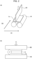
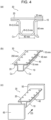
- good bending fracture characteristics means that the critical spacer thickness (ST) in the U-bending + tight bending bending test satisfies the formula (A) or (B) depending on TS, and the stroke at the maximum load (SFmax) measured in the V-bending + orthogonal VDA bending test satisfies the formula (A) or (B) depending on TS.
- the El (ductility), ⁇ (stretch flangeability), and R/t (bendability) are characteristics indicating the ease of forming a steel sheet during press forming (the degree of freedom of forming for press forming without cracking).
- the U-bending + tight bending test is a test simulating the deformation and fracture behavior of a vertical wall portion in a collision test
- the critical spacer thickness (ST) measured in the U-bending + tight bending test is a measure indicating the resistance to cracking of a steel sheet and a member of an automobile body in case of a collision (crashworthiness for absorbing impact energy without fracture).
- the V-bending + orthogonal VDA bending test is a test simulating the deformation and fracture behavior of a bending ridge line portion in a collision test, and the stroke at the maximum load (SFmax) measured in the V-bending + orthogonal VDA bending test is a measure indicating the resistance to cracking of an energy absorbing member.
- the present disclosure is based on these findings.
- the gist of the present disclosure is as follows:
- the present invention provides a steel sheet with a tensile strength TS of 1180 MPa or more, high yield stress YS and yield ratio YR, high press formability (ductility, flangeability, and bendability), and fracture resistance characteristics (bending fracture characteristics and axial compression characteristics) in case of a collision.
- a member including a steel sheet according to the present invention as a material has high strength, high press formability, and enhanced crashworthiness, and can therefore be extremely advantageously applied to a structural member, an impact energy absorbing member, and the like of an automobile.
- a steel sheet according to the present invention is a steel sheet including a base steel sheet, wherein the base steel sheet has a chemical composition containing, on a mass percent basis, C: 0.030% or more and 0.250% or less, Si: 0.01% or more and 0.75% or less, Mn: 2.00% or more and less than 3.50%, P: 0.001% or more and 0.100% or less, S: 0.0200% or less, Al: 0.010% or more and 2.000% or less, and N: 0.0100% or less, with the remainder being Fe and incidental impurities, and has a steel microstructure, as a microstructure at a quarter thickness position of the base steel sheet, in which the area fraction of ferrite: less than 20.0%, the area fraction of fresh martensite: 15.0% or less, the area fraction of retained austenite: 3.0% or less, the area fraction of bainite and tempered bainite: more than 10.0% and 70.0% or less, the area fraction of tempered martensite: 30.0% or more and 80.
- the steel sheet may have a galvanized layer as an outermost surface layer on one or both surfaces of the steel sheet.
- a steel sheet with a galvanized layer may be a galvanized steel sheet.
- the unit in the chemical composition is "% by mass” and is hereinafter expressed simply in “%” unless otherwise specified.
- C is an element effective in forming an appropriate amount of tempered martensite, bainite, tempered bainite, or the like to ensure a TS of 1180 MPa or more and high YS and YR.
- a C content of less than 0.030% results in an increase in the area fraction of ferrite and makes it difficult to achieve a TS of 1180 MPa or more. This also reduces YS and YR.
- a C content of more than 0.250% results in an increase in the area fraction of fresh martensite, excessively high TS, and lower El. This also results in an increase in the area fraction of fresh martensite, lower bendability in a V-bending test, and undesired R/t (press formability).
- the C content is 0.030% or more and 0.250% or less.
- the C content is preferably 0.080% or more.
- the C content is preferably 0.160% or less.
- Si 0.01% or more and 0.75% or less
- Si promotes ferrite transformation during annealing and in a cooling process after annealing.
- Si is an element that affects the area fraction of ferrite.
- a Si content of less than 0.01% results in a decrease in the area fraction of ferrite and lower ductility.
- a Si content of more than 0.75% results in an increase in the volume fraction of retained austenite, the formation of hard fresh martensite by deformation-induced transformation of retained austenite when a steel sheet is punched in a hole expansion test, is subjected to U-bending in a U-bending + tight bending test, or is subjected to V-bending in a V-bending + orthogonal VDA test, results in void formation and crack growth in a subsequent test, and results in undesired ⁇ , ST, and SFmax.
- the Si content is 0.01% or more and 0.75% or less.
- the Si content is preferably 0.10% or more.
- the Si content is preferably 0.70% or less.
- Mn 2.00% or more and less than 3.50%
- Mn is an element that adjusts the area fraction of tempered martensite, bainite, tempered bainite, or the like.
- a Mn content of less than 2.00% results in an increase in the area fraction of ferrite and makes it difficult to achieve a TS of 1180 MPa or more. This also reduces YS and YR.
- a Mn content of 3.50% or more results in a decrease in martensite start temperature Ms (hereinafter also referred to simply as an Ms temperature or Ms) and a decrease in martensite formed in a first cooling step.
- Ms martensite start temperature
- Ms temperature a decrease in martensite formed in a first cooling step.
- the Mn content is 2.00% or more and less than 3.50%.
- the Mn content is preferably 2.30% or more.
- the Mn content is preferably 3.30% or less.
- P is an element that has a solid-solution strengthening effect and increases TS and YS of a steel sheet. To produce such effects, the P content is 0.001% or more.
- a P content of more than 0.100% results in segregation of P at a prior-austenite grain boundary and embrittlement of the grain boundary. This results in void formation and crack growth along the prior-austenite grain boundary and undesired R/t in a V-bending test. This also results in void formation and crack growth along the prior-austenite grain boundary when a steel sheet is punched in a hole expansion test, is subjected to U-bending in a U-bending + tight bending test, or is subjected to V-bending in a V-bending + orthogonal VDA test, and undesired ⁇ , ST, and SFmax.
- the P content is 0.001% or more and 0.100% or less.
- the P content is preferably 0.030% or less.
- S is present as a sulfide in steel.
- a S content of more than 0.0200% results in void formation and crack growth from the sulfide as a starting point in a V-bending test and undesired R/t.
- This also results in void formation and crack growth from the sulfide as a starting point when a steel sheet is punched in a hole expansion test, is subjected to U-bending in a U-bending + tight bending test, or is subjected to V-bending in a V-bending + orthogonal VDA test, and undesired ⁇ , ST, and SFmax.
- the S content is 0.0200% or less.
- the S content is preferably 0.0080% or less.
- the S content may have any lower limit but is preferably 0.0001% or more due to constraints on production technology.
- Al 0.010% or more and 2.000% or less
- Al promotes ferrite transformation during annealing and in a cooling process after annealing.
- Al is an element that affects the area fraction of ferrite.
- An Al content of less than 0.010% results in a decrease in the area fraction of ferrite and lower ductility.
- an Al content of more than 2.000% results in an excessive increase in the area fraction of ferrite and makes it difficult to achieve a TS of 1180 MPa or more. This also reduces YS and YR.
- the Al content is 0.010% or more and 2.000% or less.
- the Al content is preferably 0.015% or more.
- the Al content is preferably 1.000% or less.
- N is present as a nitride in steel.
- a N content of more than 0.0100% results in void formation and crack growth from the nitride as a starting point in a V-bending test and undesired R/t.
- This also results in void formation and crack growth from the nitride as a starting point when a steel sheet is punched in a hole expansion test, is subjected to U-bending in a U-bending + tight bending test, or is subjected to V-bending in a V-bending + orthogonal VDA test, and undesired ⁇ , ST, and SFmax.
- the N content is 0.0100% or less.
- the N content is preferably 0.0050% or less.
- the N content may have any lower limit but is preferably 0.0005% or more due to constraints on production technology.
- a base chemical composition of a base steel sheet of a steel sheet according to an embodiment of the present invention has been described above.
- a base steel sheet of a steel sheet according to an embodiment of the present invention has a chemical composition that contains the base components and the remainder other than the base components including Fe (iron) and incidental impurities.
- a base steel sheet of a steel sheet according to an embodiment of the present invention preferably has a chemical composition that contains the base components and the remainder composed of Fe and incidental impurities.
- a base steel sheet of a steel sheet according to an embodiment of the present invention may contain, in addition to the base components, at least one selected from the following optional components.
- the following optional components are contained in an amount equal to or less than their respective upper limits described below, the advantages of the present invention can be achieved. Thus, there is no particular lower limit. Any of the following optional elements contained in amounts below the following appropriate lower limits is considered to be an incidental impurity.
- Nb forms fine carbide, nitride, or carbonitride during hot rolling or annealing and thereby increases TS, YS, and YR.
- the Nb content is preferably 0.001% or more.
- the Nb content is more preferably 0.005% or more.
- a Nb content of more than 0.200% may result in a large number of coarse precipitates or inclusions.
- a coarse precipitate or inclusion may act as a starting point of a void and a crack in a hole expansion test, a V-bending test, a U-bending + tight bending test, or a V-bending + orthogonal VDA bending test, and desired ⁇ , R/t, ST, and SFmax may not be achieved.
- the Nb content is preferably 0.200% or less.
- the Nb content is more preferably 0.060% or less.
- Ti forms fine carbide, nitride, or carbonitride during hot rolling or annealing and thereby increases TS, YS, and YR.
- the Ti content is preferably 0.001% or more.
- the Ti content is more preferably 0.005% or more.
- a Ti content of more than 0.200% may result in a large number of coarse precipitates or inclusions.
- a coarse precipitate or inclusion may act as a starting point of a void and a crack in a hole expansion test, a V-bending test, a U-bending + tight bending test, or a V-bending + orthogonal VDA bending test, and desired ⁇ , R/t, ST, and SFmax may not be achieved.
- the Ti content is preferably 0.200% or less.
- the Ti content is more preferably 0.060% or less.
- V 0.200% or less
- V forms fine carbide, nitride, or carbonitride during hot rolling or annealing and thereby increases TS and YS.
- the V content is preferably 0.001% or more.
- the V content is more preferably 0.005% or more.
- the V content is even more preferably 0.010% or more, and even further more preferably 0.030% or more.
- a V content of more than 0.200% may result in a large number of coarse precipitates or inclusions.
- a coarse precipitate or inclusion may act as a starting point of a void and a crack in a hole expansion test, a V-bending test, a U-bending + tight bending test, or a V-bending + orthogonal VDA bending test, and desired ⁇ , R/t, ST, and SFmax may not be achieved.
- the V content is preferably 0.200% or less.
- the V content is more preferably 0.060% or less.
- B is an element that segregates at an austenite grain boundary and enhances hardenability. B is also an element that controls the formation and grain growth of ferrite during cooling after annealing. To produce such effects, the B content is preferably 0.0001% or more. The B content is more preferably 0.0002% or more.
- the B content is even more preferably 0.0005% or more, and even further more preferably 0.0007% or more.
- a B content of more than 0.0100% may result in a crack in a steel sheet during hot rolling.
- the internal crack may act as a starting point of a crack in a hole expansion test, a V-bending test, a U-bending + tight bending test, or a V-bending + orthogonal VDA bending test, and desired ⁇ , R/t, ST, and SFmax may not be achieved.
- the B content is preferably 0.0100% or less.
- the B content is more preferably 0.0050% or less.
- Cr is an element that enhances hardenability, and the addition of Cr forms an appropriate amount of tempered martensite and increases TS, YS, and YR. To produce such effects, the Cr content is preferably 0.0005% or more. The Cr content is more preferably 0.010% or more.
- Cr is even more preferably 0.030% or more, and even further more preferably 0.050% or more.
- a Cr content of more than 1.000% may result in an increase in the area fraction of fresh martensite, lower flangeability, lower bendability in a V-bending test, and undesired ⁇ and R/t.
- the Cr content is preferably 1.000% or less.
- the Cr content is more preferably 0.800% or less, even more preferably 0.700% or less.
- Ni is an element that enhances hardenability, and the addition of Ni forms a large amount of tempered martensite and increases TS, YS, and YR. To produce such effects, the Ni content is preferably 0.005% or more.
- the Ni content is more preferably 0.020% or more.
- the Ni content is even more preferably 0.040% or more, and even further more preferably 0.060% or more.
- Ni content of more than 1.000% may result in an increase in the area fraction of fresh martensite, lower flangeability, lower bendability in a V-bending test, and undesired ⁇ and R/t.
- the Ni content is preferably 1.000% or less.
- the Ni content is more preferably 0.800% or less.
- the Ni content is even more preferably 0.600% or less, and even further more preferably 0.400% or less.
- Mo is an element that enhances hardenability, and the addition of Mo forms a large amount of tempered martensite and increases TS, YS, and YR. To produce such effects, the Mo content is preferably 0.010% or more. The Mo content is more preferably 0.030% or more.
- a Mo content of more than 1.000% may result in an increase in the area fraction of fresh martensite, lower flangeability, lower bendability in a V-bending test, and undesired ⁇ and R/t.
- the Mo content when Mo is contained, the Mo content is preferably 1.000% or less.
- the Mo content is more preferably 0.500% or less, even more preferably 0.450% or less, and even further more preferably 0.400% or less.
- the Mo content is even more preferably 0.350% or less, and even further more preferably 0.300% or less.
- Sb is an element effective in suppressing the diffusion of C near the surface of a steel sheet during annealing and controlling the formation of a soft layer near the surface of the steel sheet.
- An excessive increase of a soft layer near the surface of a steel sheet may make it difficult to achieve a TS of 1180 MPa or more. This may also reduce YS.
- the Sb content is preferably 0.002% or more.
- the Sb content is more preferably 0.005% or more.
- an Sb content of more than 0.200% may result in no soft layer near the surface of a steel sheet and lower ⁇ , R/t, ST, and SFmax.
- the Sb content is preferably 0.200% or less.
- the Sb content is more preferably 0.020% or less.
- Sn is an element effective in suppressing the diffusion of C near the surface of a steel sheet during annealing and controlling the formation of a soft layer near the surface of the steel sheet.
- An excessive increase of a soft layer near the surface of a steel sheet may make it difficult to achieve a TS of 1180 MPa or more. This may also reduce YS.
- the Sn content is preferably 0.002% or more.
- the Sn content is more preferably 0.005% or more.
- a Sn content of more than 0.200% may result in no soft layer near the surface of a steel sheet and lower ⁇ , R/t, ST, and SFmax.
- the Sn content is preferably 0.200% or less.
- the Sn content is more preferably 0.020% or less.
- Cu is an element that enhances hardenability, and the addition of Cu forms a large amount of tempered martensite and increases TS, YS, and YR. To produce such effects, the Cu content is preferably 0.005% or more. The Cu content is more preferably 0.008% or more, even more preferably 0.010% or more. The Cu content is even more preferably 0.020% or more.
- a Cu content of more than 1.000% may result in an excessive increase in the area fraction of fresh martensite. Furthermore, a large number of coarse precipitates and inclusions may be formed. In such a case, excessively formed fresh martensite or a coarse precipitate or inclusion may act as a starting point of a void and a crack in a hole expansion test, a V-bending test, a U-bending + tight bending test, or a V-bending + orthogonal VDA bending test, and desired ⁇ , R/t, ST, and SFmax may not be achieved.
- the Cu content is preferably 1.000% or less.
- the Cu content is more preferably 0.200% or less.
- Ta forms fine carbide, nitride, or carbonitride during hot rolling or annealing and increases TS, YS, and YR. Furthermore, Ta partially dissolves in Nb carbide or Nb carbonitride and forms a complex precipitate, such as (Nb, Ta) (C, N). This suppresses coarsening of a precipitate and stabilizes precipitation strengthening. This further improves TS and YS. To produce such effects, the Ta content is preferably 0.001% or more. The Ta content is more preferably 0.002% or more, even more preferably 0.004% or more.
- a Ta content of more than 0.100% may result in a large number of coarse precipitates or inclusions.
- an excessively coarse precipitate or inclusion may act as a starting point of a void and a crack in a hole expansion test, a V-bending test, a U-bending + tight bending test, or a V-bending + orthogonal VDA bending test, and desired ⁇ , R/t, ST, and SFmax may not be achieved.
- the Ta content is preferably 0.100% or less.
- the Ta content is more preferably 0.090% or less, even more preferably 0.080% or less.
- W is an element that enhances hardenability, and the addition of W forms a large amount of tempered martensite and increases TS, YS, and YR. To produce such effects, the W content is preferably 0.001% or more. The W content is more preferably 0.030% or more.
- a W content of more than 0.500% may result in an increase in the area fraction of fresh martensite, lower flangeability, lower bendability in a V-bending test, and undesired ⁇ and R/t.
- the W content is preferably 0.500% or less.
- the W content is more preferably 0.450% or less, even more preferably 0.400% or less.
- the W content is even further more preferably 0.300% or less.
- Mg is an element effective in spheroidizing the shape of an inclusion of sulfide, oxide, or the like and improving the flangeability and bendability of a steel sheet.
- the Mg content is preferably 0.0001% or more.
- the Mg content is more preferably 0.0005% or more, even more preferably 0.0010% or more.
- a Mg content of more than 0.0200% may result in a large number of coarse precipitates or inclusions.
- an excessively coarse precipitate or inclusion may act as a starting point of a void and a crack in a hole expansion test, a V-bending test, a U-bending + tight bending test, or a V-bending + orthogonal VDA bending test, and desired ⁇ , R/t, ST, and SFmax may not be achieved.
- the Mg content is preferably 0.0200% or less.
- the Mg content is more preferably 0.0180% or less, even more preferably 0.0150% or less.
- Zn is an element effective in spheroidizing the shape of an inclusion and improving the flangeability and bendability of a steel sheet. To produce such effects, the Zn content is preferably 0.0010% or more. The Zn content is more preferably 0.0020% or more, even more preferably 0.0030% or more.
- a Zn content of more than 0.0200% may result in a large number of coarse precipitates or inclusions.
- an excessively coarse precipitate or inclusion may act as a starting point of a void and a crack in a hole expansion test, a V-bending test, a U-bending + tight bending test, or a V-bending + orthogonal VDA bending test, and desired ⁇ , R/t, ST, and SFmax may not be achieved.
- the Zn content is preferably 0.0200% or less.
- the Zn content is more preferably 0.0180% or less, even more preferably 0.0150% or less.
- Co is an element effective in spheroidizing the shape of an inclusion and improving the flangeability and bendability of a steel sheet.
- the Co content is preferably 0.0010% or more.
- the Co content is more preferably 0.0020% or more, even more preferably 0.0030% or more.
- a Co content of more than 0.0200% may result in a large number of coarse precipitates or inclusions.
- an excessively coarse precipitate or inclusion may act as a starting point of a void and a crack in a hole expansion test, a V-bending test, a U-bending + tight bending test, or a V-bending + orthogonal VDA bending test, and desired ⁇ , R/t, ST, and SFmax may not be achieved.
- the Co content is preferably 0.0200% or less.
- the Co content is more preferably 0.0180% or less, even more preferably 0.0150% or less.
- Zr is an element effective in spheroidizing the shape of an inclusion and improving the flangeability and bendability of a steel sheet.
- the Zr content is preferably 0.0010% or more.
- an excessively coarse precipitate or inclusion may act as a starting point of a void and a crack in a hole expansion test, a V-bending test, a U-bending + tight bending test, or a V-bending + orthogonal VDA bending test, and desired ⁇ , R/t, ST, and SFmax may not be achieved.
- the Zr content is preferably 0.1000% or less.
- the Zr content is more preferably 0.0300% or less, even more preferably 0.0100% or less.
- Ca is present as an inclusion in steel.
- a Ca content of more than 0.0200% may result in a large number of coarse inclusions. In such a case, an excessively coarse precipitate or inclusion may act as a starting point of a void and a crack in a hole expansion test, a V-bending test, a U-bending + tight bending test, or a V-bending + orthogonal VDA bending test, and desired ⁇ , R/t, ST, and SFmax may not be achieved.
- the Ca content is preferably 0.0200% or less.
- the Ca content is preferably 0.0020% or less.
- the Ca content is more preferably 0.0019% or less, even more preferably 0.0018% or less.
- the Ca content may have any lower limit but is preferably 0.0005% or more. Due to constraints on production technology, the Ca content is more preferably 0.0010% or more.
- Se 0.0200% or less
- Te 0.0200% or less
- Ge 0.0200% or less
- Sr 0.0200% or less
- Cs 0.0200% or less
- Hf 0.0200% or less
- Pb 0.0200% or less
- Bi 0.0200% or less
- REM 0.0200% or less
- Se, Te, Ge, As, Sr, Cs, Hf, Pb, Bi, and REM are elements effective in improving the flangeability and bendability of a steel sheet.
- each of the Se, Te, Ge, As, Sr, Cs, Hf, Pb, Bi, and REM contents is preferably 0.0001% or more.
- a Se, Te, Ge, Sr, Cs, Hf, Pb, Bi, or REM content of more than 0.0200% or an As content of more than 0.0500% may result in a large number of coarse precipitates or inclusions.
- an excessively coarse precipitate or inclusion may act as a starting point of a void and a crack in a hole expansion test, a V-bending test, a U-bending + tight bending test, and a V-bending + orthogonal VDA bending test, and desired ⁇ , R/t, ST, and SFmax may not be achieved.
- each of the Se, Te, Ge, As, Sr, Cs, Hf, Pb, Bi, and REM contents is preferably 0.0200% or less, and the As content is preferably 0.0500% or less.
- the Se content is more preferably 0.0005% or more, even more preferably 0.0008% or more.
- the Se content is more preferably 0.0180% or less, even more preferably 0.0150% or less.
- the Te content is more preferably 0.0005% or more, even more preferably 0.0008% or more.
- the Te content is more preferably 0.0180% or less, even more preferably 0.0150% or less.
- the Ge content is more preferably 0.0005% or more, even more preferably 0.0008% or more.
- the Ge content is more preferably 0.0180% or less, even more preferably 0.0150% or less.
- the As content is more preferably 0.0010% or more, even more preferably 0.0015% or more.
- the As content is more preferably 0.0400% or less, even more preferably 0.0300% or less.
- the Sr content is more preferably 0.0005% or more, even more preferably 0.0008% or more.
- the Sr content is more preferably 0.0180% or less, even more preferably 0.0150% or less.
- the Cs content is more preferably 0.0005% or more, even more preferably 0.0008% or more.
- the Cs content is more preferably 0.0180% or less, even more preferably 0.0150% or less.
- the Hf content is more preferably 0.0005% or more, even more preferably 0.0008% or more.
- the Hf content is more preferably 0.0180% or less, even more preferably 0.0150% or less.
- the Pb content is more preferably 0.0005% or more, even more preferably 0.0008% or more.
- the Pb content is more preferably 0.0180% or less, even more preferably 0.0150% or less.
- the Bi content is more preferably 0.0005% or more, even more preferably 0.0008% or more.
- Bi is more preferably 0.0180% or less, even more preferably 0.0150% or less.
- REM is more preferably 0.0005% or more, even more preferably 0.0008% or more. REM is more preferably 0.0180% or less, even more preferably 0.0150% or less.
- REM scandium
- Y yttrium
- Lu lutetium
- REM concentration refers to the total content of one or two or more elements selected from the REM.
- REM is preferably, but not limited to, Sc, Y, Ce, or La.
- the area fraction of ferrite is less than 20.0% (including 0.0%).
- the area fraction of ferrite is preferably 15.0% or less.
- fresh martensite with an excessively increased area fraction acts as a starting point of void formation in a hole expanding process in a hole expansion test or in a bending process in a V-bending test, and desired ⁇ and R/t cannot be achieved.
- the area fraction of fresh martensite is 15.0% or less.
- the area fraction of fresh martensite is preferably 10.0% or less.
- fresh martensite refers to as-quenched (untempered) martensite.
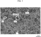
- the fresh martensite includes (isolated) island-like fresh martensite in bainite grains and in tempered bainite grains described later.
- an excessive increase in the area fraction of retained austenite results in the formation of hard fresh martensite by deformation-induced transformation of retained austenite when a steel sheet is punched in a hole expansion test, is subjected to U-bending in a U-bending + tight bending test, or is subjected to V-bending in a V-bending + orthogonal VDA test, results in void formation and crack growth in a subsequent test, and results in undesired ⁇ , ST, and SFmax.
- the area fraction of retained austenite is 3.0% or less.
- the area fraction of retained austenite is preferably 2.5% or less, more preferably 2.0% or less.
- the lower limit of the area fraction of retained austenite is preferably, but not limited to, 0.1% or more, more preferably 0.2% or more.
- the retained austenite includes (isolated) island-like retained austenite in bainite grains and in tempered bainite grains described later.
- the desired area fraction of tempered martensite can be ensured by applying a tension of 2.0 kgf/mm 2 or more to a steel sheet in the temperature range of 300°C or more and 450°C or less, then subjecting the steel sheet to five or more passes, each pass involving contact with a roll with a diameter of 500 mm or more and 1500 mm or less for a quarter circumference of the roll, to cause deformation-induced transformation of non-transformed austenite into fresh martensite, tempering the fresh martensite in a subsequent reheating step, and finally controlling the area fraction of fresh martensite to 15.0% or less and the area fraction of retained austenite to 3.0% or less.
- the term “bainite (B)” refers to a microstructure formed in the first cooling step and the intermediate holding step.
- tempered bainite (BT) refers to a microstructure in which the bainite formed in the reheating step is tempered.
- F denotes ferrite
- M denotes martensite
- RA denotes retained austenite
- TM denotes tempered martensite
- ⁇ denotes carbide.
- the area fraction of bainite and tempered bainite is 10.0% or less, it is difficult to ensure high ductility, that is, to achieve desired El. Thus, the area fraction of bainite and tempered bainite is more than 10.0%.
- the area fraction of bainite and tempered bainite is 70.0% or less.
- the area fraction of bainite and tempered bainite is preferably 15.0% or more.
- the area fraction of bainite and tempered bainite is preferably 65.0% or less.
- Tempered martensite is a microstructure formed in the reheating step.
- the hard second phase fresh martensite + retained austenite
- the hard second phase is a microstructure effective in ensuring desired TS but is a microstructure that promotes void formation and crack growth during press forming and in case of a collision.
- the area fraction of fresh martensite should be 15.0% or less
- the volume fraction of retained austenite should be 3.0% or less.
- tempered martensite is formed by applying a tension of 2.0 kgf/mm 2 or more in the temperature range of 300°C or more and 450°C or less, then subjecting a steel sheet to five or more passes, each pass involving contact with a roll with a diameter of 500 mm or more and 1500 mm or less for a quarter circumference of the roll, to cause deformation-induced transformation of non-transformed austenite into fresh martensite, and tempering the fresh martensite in a subsequent reheating step.
- the tempered martensite is a microstructure necessary to achieve desired ⁇ , R/t, ST, and SFmax.
- the area fraction of tempered martensite is 30.0% or more.
- the area fraction of tempered martensite is preferably 35.0% or more.
- the area fraction of tempered martensite is 70.0% or less.
- the area fraction of tempered martensite is preferably 60.0% or less.
- Average grain size of island-like fresh martensite and island-like retained austenite in bainite grains and in tempered bainite grains 2.00 ⁇ m or less
- isolated island-like fresh martensite and isolated island-like retained austenite in bainite grains and in tempered bainite grains have a small average grain size, it is possible to ensure a TS of 1180 MPa or more, further suppress void formation, and achieve better ⁇ , R/t, ST, and SFmax.
- the average grain size of isolated island-like fresh martensite and isolated island-like retained austenite in bainite grains and in tempered bainite grains is 2.00 ⁇ m or less.
- the average grain size of isolated island-like fresh martensite and isolated island-like retained austenite in bainite grains and in tempered bainite grains may be the average grain size of island-like fresh martensite and island-like retained austenite in the bainite grains and in the tempered bainite grains.
- the average grain size of island-like fresh martensite and island-like retained austenite in bainite grains and in tempered bainite grains is 2.00 ⁇ m or less.
- the average grain size of island-like fresh martensite and island-like retained austenite in bainite grains and in tempered bainite grains is preferably 1.00 ⁇ m or less.
- the average grain size of island-like fresh martensite and island-like retained austenite in bainite grains and in tempered bainite grains is preferably 0.10 ⁇ m or more, more preferably 0.20 ⁇ m or more.
- Average particle size of carbides in bainite grains and in tempered bainite grains 500 nm or less
- the average particle size of carbides in bainite grains and in tempered bainite grains is 500 nm or less.
- the average particle size of carbides in bainite grains and in tempered bainite grains is preferably 300 nm or less.
- the average particle size of carbides in bainite grains and in tempered bainite grains is preferably 50 nm or more, more preferably 80 nm or more.
- the number density of carbides with a particle size of 300 nm or more in bainite grains and in tempered bainite grains has a small number density, it is possible to ensure a TS of 1180 MPa or more, further suppress void formation, and achieve better ⁇ , R/t, ST, and SFmax.
- the number density of carbides with a particle size of 300 nm or more in bainite grains and in tempered bainite grains is 3.0 / ⁇ m 2 or less.
- the number density of carbides with a particle size of 300 nm or more in bainite grains and in tempered bainite grains is preferably 2.5 / ⁇ m 2 or less.
- the number density of carbides in bainite grains and in tempered bainite grains is preferably 0.2 / ⁇ m 2 or more, more preferably 0.5 / ⁇ m 2 or more.
- the area fraction of the remaining microstructure other than the ferrite, fresh martensite, retained austenite, bainite, tempered bainite, and tempered martensite is preferably 10.0% or less.
- the area fraction of the remaining microstructure is more preferably 5.0% or less.
- the area fraction of the remaining microstructure may be 0.0%.
- the remaining microstructure is, for example, but not limited to, unrecrystallized ferrite, pearlite, or the like.
- the type of the remaining microstructure can be determined, for example, by scanning electron microscope (SEM) observation.
- the area fractions of ferrite, bainite, tempered bainite, tempered martensite, and the hard second phase are measured at a quarter thickness position of a base steel sheet as described below.
- a sample is cut out to form a thickness cross section (L cross section) parallel to the rolling direction of a steel sheet as an observation surface.
- the observation surface of the sample is then polished with a diamond paste and is then subjected to final polishing with alumina.
- the observation surface of the sample is then etched with 3% by volume nital to expose the microstructure.
- the steel sheet is then observed at a quarter thickness position using a SEM at a magnification of 3000 times in five visual fields.
- the area fraction is calculated by dividing the area of each constituent microstructure (ferrite, bainite, tempered bainite, tempered martensite, and the hard second phase (fresh martensite + retained austenite)) by the measurement area in five visual fields using Adobe Photoshop available from Adobe Systems, and the area fractions are averaged to determine the area fraction of each microstructure.
- Isolated island-like fresh martensite and isolated island-like retained austenite in bainite grains and in tempered bainite grains are extracted by manual color-coding from the SEM image used for the microstructure fraction measurement, and the average grain size of the isolated island-like fresh martensite and the isolated island-like retained austenite in the bainite grains and in the tempered bainite grains are determined using ImageJ from an open source.
- the average grain size is an equivalent circular diameter calculated by dividing the total area of the island-like fresh martensite and the island-like retained austenite by the numbers of island-like fresh martensite pieces and island-like retained austenite pieces to obtain an average area, dividing the average area by the circumference ratio ⁇ , and multiplying the square root thereof by 2.
- an island-like region with the outer periphery surrounded by bainite and/or tempered bainite and integrally formed without interruption is regarded as a piece to be measured.
- carbides in the bainite grains and in the tempered bainite grains are extracted by manual color-coding from the SEM image used for the microstructure fraction measurement, and the average particle size of the carbides in the bainite grains and in the tempered bainite grains and the number density of carbides with a particle size of 300 nm or more among the carbides in the bainite grains and in the tempered bainite grains are determined using ImageJ from an open source.
- the average particle size is an equivalent circular diameter calculated by dividing the total area of carbides by the number of carbides to obtain an average area, dividing the average area by the circumference ratio ⁇ , and multiplying the square root thereof by 2.
- an island-like region with the outer periphery surrounded by bainite and/or tempered bainite and integrally formed without interruption is regarded as a piece to be measured.
- the area fraction of retained austenite is measured as described below.
- a base steel sheet is mechanically ground to a quarter thickness position in the thickness direction (depth direction) and is then chemically polished with oxalic acid to form an observation surface.
- the observation surface is then observed by X-ray diffractometry.
- a MoK ⁇ radiation source is used for incident X-rays to determine the ratio of the diffraction intensity of each of (200), (220), and (311) planes of fcc iron (austenite) to the diffraction intensity of each of (200), (211), and (220) planes of bcc iron.
- the volume fraction of retained austenite is calculated from the ratio of the diffraction intensity of each plane. On the assumption that retained austenite is three-dimensionally homogeneous, the volume fraction of retained austenite is defined as the area fraction of the retained austenite.
- the area fraction of fresh martensite is determined by subtracting the area fraction of retained austenite from the area fraction of the hard second phase determined as described above.
- [Area fraction of fresh martensite (%)] [area fraction (%) of hard second phase] - [area fraction (%) of retained austenite]
- the area fraction of the remaining microstructure is determined by subtracting the area fraction of ferrite, the area fraction of bainite and tempered bainite, the area fraction of tempered martensite, and the area fraction of the hard second phase, which are determined as described above, from 100.0%.
- [Area fraction of remaining microstructure (%)] 100.0 - [area fraction of ferrite (%)] - [area fraction of bainite and tempered bainite (%)] - [area fraction of tempered martensite (%)] - [area fraction of hard second phase (%)]
- the amount of diffusible hydrogen in a steel sheet is preferably 0.25 ppm by mass or less.
- the amount of diffusible hydrogen in a steel sheet may have any lower limit and is preferably 0.01 ppm by mass or more due to constraints on production technology.
- a base steel sheet in which the amount of diffusible hydrogen is measured may be, in addition to a high-strength steel sheet before coating treatment, a base steel sheet of a high-strength galvanized steel sheet after galvanizing treatment and before processing. It may also be a base steel sheet of a steel sheet subjected to processing, such as punching or stretch flange forming, after galvanizing treatment, or a base portion of a product produced by welding a steel sheet after processing.
- the amount of diffusible hydrogen in a steel sheet is measured by the following method.
- a test specimen with a length of 30 mm and a width of 5 mm is taken and, when a galvanized layer is formed on the steel sheet, the hot-dip galvanized layer or hot-dip galvannealed layer is removed with an alkali.
- the amount of hydrogen released from the test specimen is then measured by a temperature-programmed desorption analysis method. More specifically, the test specimen is continuously heated from room temperature (-5°C to 55°C) to 300°C at a heating rate of 200°C/h and is then cooled to room temperature.
- the cumulative amount of hydrogen released from the test specimen from room temperature to 210°C is measured as the amount of diffusible hydrogen in the steel sheet.
- the amount of diffusible hydrogen is preferably measured after the completion of the production of the steel sheet.
- the amount of hydrogen is more preferably measured within one week after the completion of the production of the steel sheet.
- the room temperature should be within the range of annual temperature variations at the location in consideration of global production. Typically, it preferably ranges from 10°C to 50°C.
- a base steel sheet of a steel sheet according to an embodiment of the present invention preferably has a surface soft layer on the surface of the base steel sheet.
- the surface soft layer contributes to the suppression of the development of flex cracking during press forming and in case of a collision of an automobile body and therefore further improves bending fracture resistance characteristics.
- the term "surface soft layer” means a decarburized layer and refers to a surface layer region with a Vickers hardness of 85% or less with respect to the Vickers hardness of a cross section at a quarter thickness position.
- the surface soft layer is formed in a region of 200 ⁇ m or less from the surface of the base steel sheet in the thickness direction.
- the region where the surface soft layer is formed is preferably 150 ⁇ m or less, more preferably 120 ⁇ m or less, from the surface of the base steel sheet in the thickness direction.
- the lower limit of the thickness of the surface soft layer is preferably, but not limited to, 7 ⁇ m or more, more preferably more than 14 ⁇ m.
- the surface soft layer is preferably 30 ⁇ m or more, more preferably 40 ⁇ m or more.
- the quarter thickness position of the base steel sheet where the Vickers hardness is measured is a non-surface-soft layer (a layer that does not satisfy the condition of the hardness of the surface soft layer defined in the present invention).
- the Vickers hardness is measured at a load of 10 gf in accordance with JIS Z 2244-1 (2020).
- the ratio of the number of measurements in which the nanohardness of the sheet surface at the quarter depth position in the thickness direction of the surface soft layer from the surface of the base steel sheet is 7.0 GPa or more is 0.10 or less with respect to the total number of measurements at the quarter depth position in the thickness direction of the surface soft layer.
- the ratio of the number of measurements in which the nanohardness of the sheet surface at the quarter depth position in the thickness direction of the surface soft layer from the surface of the base steel sheet is 7.0 GPa or more is preferably 0.10 or less with respect to the total number of measurements at the quarter depth position in the thickness direction of the surface soft layer.
- the ratio of the nanohardness of 7.0 GPa or more is 0.10 or less, it means a low ratio of a hard microstructure (martensite or the like), an inclusion, or the like, and this can further suppress the formation and connection of voids and crack growth in the hard microstructure (martensite and the like), inclusion, or the like during press forming and in case of a collision, thus resulting in good R/t and SFmax.
- the nanohardness of the sheet surface at the quarter depth position in the thickness direction of the surface soft layer from the surface of the steel sheet has a standard deviation ⁇ of 1.8 GPa or less
- the nanohardness of the sheet surface at the half depth position in the thickness direction of the surface soft layer from the surface of the steel sheet has a standard deviation ⁇ of 2.2 GPa or less.
- the nanohardness of the sheet surface at the quarter depth position in the thickness direction of the surface soft layer from the surface of the steel sheet preferably has a standard deviation ⁇ of 1.8 GPa or less
- the nanohardness of the sheet surface at the half depth position in the thickness direction of the surface soft layer from the surface of the steel sheet preferably has a standard deviation ⁇ of 2.2 GPa or less.
- the nanohardness of the sheet surface at the quarter depth position in the thickness direction of the surface soft layer from the surface of the base steel sheet preferably has a standard deviation ⁇ of 1.7 GPa or less.
- the nanohardness of the sheet surface at the quarter depth position in the thickness direction of the surface soft layer from the surface of the base steel sheet more preferably has a standard deviation ⁇ of 1.3 GPa or less.
- the standard deviation ⁇ of the nanohardness of the sheet surface at the quarter depth position in the thickness direction of the surface soft layer from the surface of the base steel sheet may have any lower limit and may be 0.5 GPa or more.
- the nanohardness of the sheet surface at the half depth position in the thickness direction of the surface soft layer from the surface of the base steel sheet more preferably has a standard deviation ⁇ of 2.1 GPa or less.
- the nanohardness of the sheet surface at the half depth position in the thickness direction of the surface soft layer from the surface of the base steel sheet more preferably has a standard deviation ⁇ of 1.7 GPa or less.
- the standard deviation ⁇ of the nanohardness of the sheet surface at the half depth position in the thickness direction of the surface soft layer from the surface of the base steel sheet may have any lower limit and may be 0.6 GPa or more.
- nanohardness of a sheet surface at a quarter depth position and at a half depth position in the thickness direction refers to a hardness measured by the following method.
- the coated layer to be peeled off is a galvanized layer when the galvanized layer is formed, is a metal coated layer when the metal coated layer is formed, or is a galvanized layer and a metal coated layer when the galvanized layer and the metal coated layer are formed.
- the nanohardness is measured with Hysitron tribo-950 and a Berkovich diamond indenter under the conditions of a load of 500 ⁇ N, a measurement area of 50 ⁇ m x 50 ⁇ m, and a dot-to-dot distance of 2 ⁇ m.
- nanohardness is measured with Hysitron tribo-950 and a Berkovich diamond indenter under the conditions of a load of 500 ⁇ N, a measurement area of 50 ⁇ m x 50 ⁇ m, and a dot-to-dot distance of 2 ⁇ m.
- the nanohardness is measured at 300 points or more at the quarter depth position in the thickness direction, and the nanohardness is measured at 300 points or more at the half depth position in the thickness direction.
- the quarter position is a position of 25 ⁇ m from the surface of the surface soft layer
- the half position is a position of 50 ⁇ m from the surface of the surface soft layer.
- the nanohardness is measured at 300 points or more at the position of 25 ⁇ m, and the nanohardness is also measured at 300 points or more at the position of 50 ⁇ m.
- a steel sheet according to an embodiment of the present invention preferably has a metal coated layer (first coated layer, precoated layer) on one or both surfaces of a base steel sheet (the metal coated layer (first coated layer) excludes a hot-dip galvanized layer and a galvanized layer of a hot-dip galvannealed layer).
- the metal coated layer is preferably a metal electroplated layer, and the metal electroplated layer is described below as an example.
- the metal electroplated layer When the metal electroplated layer is formed on the surface of a steel sheet, the metal electroplated layer as the outermost surface layer contributes to the suppression of the occurrence of flex cracking during press forming and in case of a collision of an automobile body and therefore further improves the bending fracture resistance characteristics.
- the dew point can be more than -20°C to further increase the thickness of the soft layer and significantly improve axial compression characteristics.
- the dew point due to a metal coated layer, even when the dew point is - 20°C or less and the soft layer has a small thickness, axial compression characteristics equivalent to those in the case where the soft layer has a large thickness can be achieved.
- the metal species of the metal electroplated layer may be any of Cr, Mn, Fe, Co, Ni, Cu, Ga, Ge, As, Ru, Rh, Pd, Ag, Cd, In, Sn, Sb, Os, Ir, Rt, Au, Hg, Ti, Pb, and Bi and is preferably Fe.
- an Fe-based electroplated layer is described below as an example, the following conditions for Fe can also be applied to other metal species.
- the coating weight of the Fe-based electroplated layer is more than 0 g/m 2 , preferably 2.0 g/m 2 or more.
- the upper limit of the coating weight per side of the Fe-based electroplated layer is not particularly limited, and from the perspective of cost, the coating weight per side of the Fe-based electroplated layer is preferably 60 g/m 2 or less.
- the coating weight of the Fe-based electroplated layer is preferably 50 g/m 2 or less, more preferably 40 g/m 2 or less, even more preferably 30 g/m 2 or less.
- the coating weight of the Fe-based electroplated layer is measured as described below.
- a sample with a size of 10 x 15 mm is taken from the Fe-based electroplated steel sheet and is embedded in a resin to prepare a cross-section embedded sample.
- Three arbitrary places on the cross section are observed with a scanning electron microscope (SEM) at an acceleration voltage of 15 kV and at a magnification of 2,000 to 10,000 times depending on the thickness of the Fe-based coated layer.
- SEM scanning electron microscope
- the average thickness of the three visual fields is multiplied by the specific gravity of iron to convert it into the coating weight per side of the Fe-based electroplated layer.
- the Fe-based electroplated layer may be, in addition to pure Fe, an alloy coated layer, such as an Fe-B alloy, an Fe-C alloy, an Fe-P alloy, an Fe-N alloy, an Fe-O alloy, an Fe-Ni alloy, an Fe-Mn alloy, an Fe-Mo alloy, or an Fe-W alloy.
- the Fe-based electroplated layer may have any chemical composition and preferably has a chemical composition containing 10% by mass or less in total of one or two or more elements selected from the group consisting of B, C, P, N, O, Ni, Mn, Mo, Zn, W, Pb, Sn, Cr, V, and Co, with the remainder being Fe and incidental impurities.
- the C content is preferably 0.08% by mass or less.
- a steel sheet according to an embodiment of the present invention has a tensile strength of 1180 MPa or more.
- the yield stress (YS), the yield ratio (YR), the total elongation (El), the limiting hole expansion ratio (A), the reference values of the critical spacer thickness (ST) in a U-bending + tight bending test and the stroke at the maximum load (SFmax) in a V-bending + orthogonal VDA bending test, and the presence or absence of fracture (appearance crack) in the axial compression test of a steel sheet according to an embodiment of the present invention are as described above.
- the tensile strength (TS), the yield stress (YS), the yield ratio (YR), and the total elongation (El) are measured in the tensile test according to JIS Z 2241 (2011) described later in Examples.
- the limiting hole expansion ratio ( ⁇ ) is measured in the hole expansion test according to JIS Z 2256 (2020) described later in Examples.
- the critical spacer thickness (ST) is measured in a U-bending + tight bending test described later in Examples.
- the stroke at the maximum load (SFmax) in the V-bending + orthogonal VDA bending test is measured in a V-bending + orthogonal VDA bending test described later in Examples.
- the presence or absence of fracture (appearance crack) in the axial compression test is measured in an axial compression test described later in Examples.
- a steel sheet according to an embodiment of the present invention may have a galvanized layer formed on a base steel sheet (on the surface of the base steel sheet or on the surface of a metal coated layer when the metal coated layer is formed) as the outermost surface layer, and the galvanized layer may be provided on only one surface or both surfaces of the base steel sheet.
- a steel sheet with a galvanized layer may be a galvanized steel sheet.
- a steel sheet according to the present invention may have a base steel sheet and a second coated layer (a galvanized layer, an aluminum coated layer, or the like) formed on the base steel sheet or may have a base steel sheet and a metal coated layer (a first coated layer (excluding a second coated layer of a galvanized layer)) and a second coated layer (a galvanized layer, an aluminum coated layer, or the like) sequentially formed on the base steel sheet.
- galvanized layer refers to a coated layer containing Zn as a main component (Zn content: 50.0% or more), for example, a hot-dip galvanized layer or a hot-dip galvannealed layer.
- the hot-dip galvanized layer is preferably composed of, for example, Zn, 20.0% by mass or less of Fe, and 0.001% by mass or more and 1.0% by mass or less of Al.
- the hot-dip galvanized layer may optionally contain one or two or more elements selected from the group consisting of Pb, Sb, Si, Sn, Mg, Mn, Ni, Cr, Co, Ca, Cu, Li, Ti, Be, Bi, and REM in a total amount of 0.0% by mass or more and 3.5% by mass or less.
- the hot-dip galvanized layer more preferably has an Fe content of less than 7.0% by mass. The remainder other than these elements is incidental impurities.
- the hot-dip galvannealed layer is preferably composed of, for example, Zn, 20.0% by mass or less of Fe, and 0.001% by mass or more and 1.0% by mass or less of Al.
- the hot-dip galvannealed layer may optionally contain one or two or more elements selected from the group consisting of Pb, Sb, Si, Sn, Mg, Mn, Ni, Cr, Co, Ca, Cu, Li, Ti, Be, Bi, and REM in a total amount of 0.0% by mass or more and 3.5% by mass or less.
- the hot-dip galvannealed layer more preferably has an Fe content of 7.0% by mass or more, even more preferably 8.0% by mass or more.
- the hot-dip galvannealed layer more preferably has an Fe content of 15.0% by mass or less, even more preferably 12.0% by mass or less. The remainder other than these elements is incidental impurities.
- the coating weight per side of the galvanized layer is preferably, but not limited to, 20 g/m 2 or more.
- the coating weight per side of the galvanized layer is preferably 80 g/m 2 or less.
- the coating weight of the galvanized layer is measured as described below.
- a treatment liquid is prepared by adding 0.6 g of a corrosion inhibitor for Fe ("IBIT 700BK” (registered trademark) manufactured by Asahi Chemical Co., Ltd.) to 1 L of 10% by mass aqueous hydrochloric acid.
- a steel sheet as a sample is immersed in the treatment liquid to dissolve a galvanized layer.
- the mass loss of the sample due to the dissolution is measured and is divided by the surface area of a base steel sheet (the surface area of a coated portion) to calculate the coating weight (g/m 2 ).
- the thickness of a steel sheet according to an embodiment of the present invention is preferably, but not limited to, 0.5 mm or more.
- the thickness is more preferably more than 0.8 mm.
- the thickness is even more preferably 0.9 mm or more.
- the thickness is more preferably 1.0 mm or more.
- the thickness is even more preferably 1.2 mm or more.
- the steel sheet preferably has a thickness of 3.5 mm or less.
- the thickness is more preferably 2.3 mm or less.
- the width of a steel sheet according to the present invention is preferably, but not limited to, 500 mm or more, more preferably 750 mm or more.
- the steel sheet preferably has a width of 1600 mm or less, more preferably 1450 mm or less.
- a method for producing a steel sheet according to the present invention includes a hot rolling step of hot-rolling a steel slab with the chemical composition described above under a condition of a finish rolling temperature of 820°C or more to produce a hot-rolled steel sheet; an annealing step of annealing the steel sheet after the hot rolling step under conditions of an annealing temperature of (Ac 1 + (Ac 3 - Ac 1 ) x 5/8) °C or more and 950°C or less and an annealing time of 20 seconds or more; a first cooling step of cooling the steel sheet to a temperature range of 300°C or more and 550°C or less after the annealing step; an intermediate holding step of holding the steel sheet under conditions of an intermediate holding temperature of 300°C or more and 550°C or less and a holding time of 20 seconds or more after the first cooling step; a second cooling step of applying a tension of 2.0 kgf/mm 2 or more to the steel sheet after the intermediate holding step in the temperature range of 300°C or more
- a steel material can be melted by any method, for example, by a known melting method using a converter, an electric arc furnace, or the like.
- a steel slab is preferably produced by continuous casting but may also be produced by ingot casting, thin slab casting, or the like. After a steel slab is produced, the steel slab may be temporarily cooled to room temperature and then reheated by a known method. Alternatively, without being cooled to room temperature, a steel slab may be subjected without problems to an energy-saving process, such as hot charge rolling or hot direct rolling, in which a hot slab is charged directly into a furnace or is immediately rolled after slight heat retention.
- the slab heating temperature is preferably 1100°C or more from the perspective of melting carbide and reducing rolling force.
- the slab heating temperature is preferably 1300°C or less to prevent an increase in scale loss.
- the slab heating temperature is the surface temperature of the slab.
- a slab is formed into a sheet bar by rough rolling under typical conditions.
- the sheet bar is preferably heated with a bar heater or the like before finish rolling.
- Finish rolling temperature 820°C or more
- Finish rolling reduces the ductility, flangeability, and bendability of the final material as a result of an increase in rolling load or an increase in rolling reduction in an unrecrystallized state of austenite and development of an abnormal microstructure elongated in the rolling direction.
- the finish rolling temperature is 820°C or more.
- the finish rolling temperature is preferably 830°C or more, more preferably 850°C or more.
- the finish rolling temperature is preferably 1080°C or less, more preferably 1050°C or less.
- the coiling temperature after hot rolling is not particularly limited, but it is necessary to consider the case where the ductility, flangeability, and bendability of the final material degrade.
- the coiling temperature after hot rolling is preferably 300°C or more.
- the coiling temperature after hot rolling is preferably 700°C or less.
- Rough-rolled sheets may be joined together during hot rolling to continuously perform finish rolling.
- a rough-rolled sheet may be temporarily coiled.
- the finish rolling may be partly or entirely rolling with lubrication.
- the rolling with lubrication is also effective in making the shape and the material quality of a steel sheet uniform.
- the friction coefficient in the rolling with lubrication is preferably 0.10 or more.
- the friction coefficient in the rolling with lubrication is preferably 0.25 or less.
- a hot-rolled steel sheet thus produced may be pickled.
- Pickling can remove an oxide from the surface of the steel sheet and can therefore be performed to ensure high chemical convertibility and quality of coating of a high-strength steel sheet of the final product.
- Pickling may be performed once or may be divided into a plurality of times.
- a pickled sheet after hot rolling or a hot-rolled steel sheet thus produced is cold-rolled as required.
- a pickled sheet may be directly cold-rolled or may be cold-rolled after heat treatment.
- a cold-rolled steel sheet after the cold rolling may be pickled.
- the cold rolling is, for example, multi-pass rolling requiring two or more passes, such as tandem multi-stand rolling or reverse rolling.
- Rolling reduction of optional cold rolling 20% or more and 80% or less
- the rolling reduction (cumulative rolling reduction ratio) in the cold rolling is preferably, but not limited to, 20% or more and 80% or less.
- a rolling reduction of less than 20% in the cold rolling tends to result in coarsening or a lack of uniformity of the steel microstructure in the annealing step and may result in the final product with lower TS or bendability.
- the rolling reduction in the cold rolling is preferably 20% or more.
- a rolling reduction of more than 80% in the cold rolling tends to result in a steel sheet with a poor shape and may result in an uneven galvanizing coating weight.
- the rolling reduction in the cold rolling is preferably 80% or less.
- An embodiment of the present invention may include a first coating step of performing metal coating on one or both surfaces of a steel sheet after the hot rolling step (after a cold rolling step when cold rolling is performed) and before an annealing step to form a metal coated layer (first coated layer).
- a metal electroplating treatment may be performed on the surface of the hot-rolled steel sheet or the cold-rolled steel sheet thus formed to produce a metal electroplated steel sheet before annealing in which a metal electroplated layer before annealing is formed on at least one surface thereof.
- metal coating excludes galvanizing (second coating).
- the metal electroplating treatment method is not particularly limited, as described above, the metal coated layer formed on the base steel sheet is preferably a metal electroplated layer, and the metal electroplating treatment is therefore preferably performed.
- a sulfuric acid bath, a hydrochloric acid bath, a mixture of both, or the like can be used as an Fe-based electroplating bath.
- the coating weight of the metal electroplated layer before annealing can be adjusted by the energization time or the like.
- the phrase "metal electroplated steel sheet before annealing" means that the metal electroplated layer is not subjected to an annealing step, and does not exclude a hot-rolled steel sheet, a pickled sheet after hot rolling, or a cold-rolled steel sheet each annealed in advance before a metal electroplating treatment.
- the metal species of the electroplated layer may be any of Cr, Mn, Fe, Co, Ni, Cu, Ga, Ge, As, Ru, Rh, Pd, Ag, Cd, In, Sn, Sb, Os, Ir, Rt, Au, Hg, Ti, Pb, and Bi and is preferably Fe.
- Fe-based electroplating is described below as an example, the following conditions for the Fe-based electroplating can also be applied to another metal electroplating.
- the Fe ion content of an Fe-based electroplating bath before the start of energization is preferably 0.5 mol/L or more in terms of Fe 2+ .
- the Fe ion content of an Fe-based electroplating bath before the start of energization is preferably 2.0 mol/L or less.
- the Fe-based electroplating bath may contain an Fe ion and at least one element selected from the group consisting of B, C, P, N, O, Ni, Mn, Mo, Zn, W, Pb, Sn, Cr, V, and Co.
- the total content of these elements in the Fe-based electroplating bath is preferably such that the total content of these elements in an Fe-based electroplated layer before annealing is 10% by mass or less.
- a metal element may be contained as a metal ion, and a non-metal element can be contained as part of boric acid, phosphoric acid, nitric acid, an organic acid, or the like.
- An iron sulfate coating solution may contain a conductive aid, such as sodium sulfate or potassium sulfate, a chelating agent, or a pH buffer.
- the temperature of an Fe-based electroplating solution is preferably 30°C or more and 85°C or less in view of constant temperature retention ability.
- the pH of the Fe-based electroplating bath is also not particularly limited, is preferably 1.0 or more from the perspective of preventing a decrease in current efficiency due to hydrogen generation, and is preferably 3.0 or less in consideration of the electrical conductivity of the Fe-based electroplating bath.
- the electric current density is preferably 10 A/dm 2 or more from the perspective of productivity and is preferably 150 A/dm 2 or less from the perspective of facilitating the control of the coating weight of an Fe-based electroplated layer.
- the line speed is preferably 5 mpm or more from the perspective of productivity and is preferably 150 mpm or less from the perspective of stably controlling the coating weight.
- a degreasing treatment and water washing for cleaning the surface of a steel sheet and also a pickling treatment and water washing for activating the surface of a steel sheet can be performed as a treatment before Fe-based electroplating treatment. These pretreatments are followed by an Fe-based electroplating treatment.
- the degreasing treatment and water washing may be performed by any method, for example, by a usual method.
- various acids such as sulfuric acid, hydrochloric acid, nitric acid, and mixtures thereof can be used. Among them, sulfuric acid, hydrochloric acid, or a mixture thereof is preferred.
- the acid concentration is not particularly limited and preferably ranges from 1% to 20% by mass in consideration of the capability of removing an oxide film, prevention of a rough surface (surface defect) due to overpickling, and the like.
- a pickling treatment liquid may contain an antifoaming agent, a pickling accelerator, a pickling inhibitor, or the like.
- An embodiment of the present invention includes an annealing step of annealing a steel sheet under conditions of an annealing temperature of (Ac 1 + (Ac 3 - Ac 1 ) ⁇ 5/8) °C or more and 950°C or less and a holding time of 20 seconds or more after the hot rolling step (after a cold rolling step when cold rolling is performed, after a metal coating step when metal coating is performed to form a metal coated layer (first coated layer), or after a metal coating step when cold rolling and metal coating are performed).
- Annealing temperature (Ac 1 + (Ac 3 - Ac 1 ) ⁇ 5/8) °C or more and 950°C or less
- An annealing temperature lower than (Ac 1 + (Ac 3 - Ac 1 ) ⁇ 5/8) °C results in an insufficient proportion of austenite formed during heating in a two-phase region of ferrite and austenite. This results in an excessive increase in the area fraction of ferrite after annealing and undesired TS, YS, and YR.
- an annealing temperature of more than 950°C results in coarse austenite grains, finally results in the average grain size of isolated island-like fresh martensite and isolated island-like retained austenite in bainite grains and in tempered bainite grains exceeding 2.00 ⁇ m, and makes it difficult to achieve good ⁇ , R/t, ST, and SFmax.
- the annealing temperature is (Ac 1 + (Ac 3 - Ac 1 ) ⁇ 5/8) °C or more and 950°C or less.
- the annealing temperature is preferably 900°C or less.
- the annealing temperature is the highest temperature reached in the annealing step.
- Annealing time 20 seconds or more
- an annealing time of less than 20 seconds results in an insufficient proportion of austenite formed during heating in a two-phase region of ferrite and austenite. This results in an excessive increase in the area fraction of ferrite after annealing, and TS, YS, and YR cannot be achieved.
- the annealing time is 20 seconds or more.
- the annealing time is preferably 30 seconds or more, more preferably 50 seconds or more.
- the annealing time may have any upper limit and is preferably 900 seconds or less, more preferably 800 seconds or less.
- the annealing time is even more preferably 300 seconds or less, even further more preferably 220 seconds or less.
- annealing time refers to the holding time in the temperature range of (annealing temperature - 40°C) or more and the annealing temperature or less.
- the annealing time includes, in addition to the holding time at the annealing temperature, the residence time in the temperature range of (annealing temperature - 40°C) or more and the annealing temperature or less in heating and cooling before and after reaching the annealing temperature.
- the number of annealing processes may be two or more but is preferably one from the perspective of energy efficiency.
- Dew-point temperature of atmosphere in annealing step (annealing atmosphere): -30°C or more
- the dew point of the atmosphere in the annealing step is preferably -30°C or more.
- Annealing at a dew point of -30°C or more in the annealing atmosphere in the annealing step can promote a decarburization reaction and more deeply form a surface soft layer.
- the dew point in the annealing atmosphere in the annealing step is more preferably -25°C or more, even more preferably more than - 20°C, even further more preferably -15°C or more, most preferably -5°C or more.
- the dew point of the annealing atmosphere in the annealing step may have any upper limit and is preferably 30°C or less in order to suitably prevent oxidation of the surface of an Fe-based electroplated layer and to improve the coating adhesion when a galvanized layer is provided.
- the dew point in the annealing atmosphere in the annealing step is preferably 25°C or less, more preferably 20°C or less.
- the present invention includes, after the annealing step, the first cooling step of setting the first cooling stop temperature to 300°C or more and 550°C or less and performing cooling to the first cooling stop temperature.
- First cooling stop temperature 300°C or more and 550°C or less
- the area fraction of bainite and tempered bainite is 10.0% or less, and it is difficult to ensure high ductility, that is, to achieve desired El.
- the average grain size of isolated island-like fresh martensite and isolated island-like retained austenite in bainite grains and in tempered bainite grains being more than 2.00 ⁇ m.
- the first cooling stop temperature is set to 300°C or more and 550°C or less, and cooling is performed to the first cooling stop temperature.
- Intermediate holding temperature 300°C or more and 550°C or less
- intermediate holding time 20 seconds or more
- the intermediate holding step holding is performed under conditions of an intermediate holding temperature of 300°C or more and 550°C or less and a holding time of 20 seconds or more.
- an intermediate holding temperature of less than 300°C or more than 550°C or a holding time (intermediate holding time) of 20 seconds or more the area fraction of bainite and tempered bainite is 10.0% or less, and it is difficult to ensure high ductility, that is, to achieve desired El.
- This also results in the average grain size of isolated island-like fresh martensite and isolated island-like retained austenite in bainite grains and in tempered bainite grains being more than 2.00 ⁇ m.
- the intermediate holding step holding is performed under conditions of an intermediate holding temperature of 300°C or more and 550°C or less and a holding time (intermediate holding time) of 20 seconds or more.
- the steel sheet may be subjected to a galvanizing treatment.
- a galvanized steel sheet can be produced by the galvanizing treatment.
- the galvanizing treatment is, for example, a hot-dip galvanizing treatment or a galvannealing treatment.
- the steel sheet is immersed in a galvanizing bath at 440°C or more and 500°C or less, and the coating weight is then adjusted by gas wiping or the like.
- the hot-dip galvanizing bath is not particularly limited as long as the galvanized layer has the composition described above.
- the galvanizing bath preferably has a composition with an Al content of 0.10% by mass or more, the remainder being Zn and incidental impurities.
- the Al content is preferably 0.23% by mass or less.
- a hot-dip galvanized steel sheet is preferably heated to an alloying temperature of 450°C or more to perform an alloying treatment.
- the alloying temperature is preferably 600°C or less.
- An alloying temperature of less than 450°C may result in a low Zn-Fe alloying speed and make alloying difficult.
- an alloying temperature of more than 600°C results in transformation of non-transformed austenite into pearlite and makes it difficult to achieve a TS of 1180 MPa or more.
- the alloying temperature is more preferably 500°C or more, even more preferably 510°C or more.
- the alloying temperature is more preferably 570°C or less.
- the coating weight of each of the hot-dip galvanized steel sheet (GI) and the hot-dip galvannealed steel sheet (GA) is preferably 20 g/m 2 or more per side.
- the coating weight per side of the galvanized layer is preferably 80 g/m 2 or less.
- the coating weight can be adjusted by gas wiping or the like.
- the present invention includes, after the intermediate holding step (after a galvanizing step when the galvanizing step is performed), a second cooling step of applying a tension of 2.0 kgf/mm 2 or more to a steel sheet in the temperature range of 300°C or more and 450°C or less, subjecting the steel sheet to five or more passes, each pass involving contact with a roll with a diameter of 500 mm or more and 1500 mm or less for a quarter circumference of the roll, and then cooling the steel sheet to a cooling stop temperature (second cooling stop temperature) of less than 300°C.
- applying a tension of 2.0 kgf/mm 2 or more to a steel sheet once or more can transform most of austenite into martensite by deformation-induced transformation (stress-strain-induced transformation), and subsequent tempering in the reheating step can reduce the area fraction of fresh martensite in the final microstructure and ensure an appropriate amount of tempered martensite. This can also reduce the amount of austenite immediately after the second cooling step and reduce the volume fraction of retained austenite in the final microstructure. Consequently, desired ⁇ , R/t, ST, and SFmax can be achieved.
- the load cells should be arranged parallel to the direction of the tension.
- the load cells are preferably disposed at a position of 200 mm from both ends of the roll.
- the length of the roll to be used is preferably 1500 mm or more.
- the length of the roll to be used is preferably 2500 mm or less.
- the tension is preferably 2.2 kgf/mm 2 or more, more preferably 2.4 kgf/mm 2 or more.
- the tension is preferably 15.0 kgf/mm 2 or less, more preferably 10.0 kgf/mm 2 or less.
- the tension is even more preferably 7.0 kgf/mm 2 or less, even further more preferably 4.0 kgf/mm 2 or less.
- subjecting a steel sheet to five or more passes, each pass involving contact with a roll with a diameter of 500 mm or more and 1500 mm or less for a quarter circumference of the roll can transform most of austenite into martensite by deformation-induced transformation (stress-strain-induced transformation), and subsequent tempering in the reheating step can reduce the area fraction of fresh martensite in the final microstructure and ensure an appropriate amount of tempered martensite. This can also reduce the amount of austenite immediately after the second cooling step and reduce the volume fraction of retained austenite in the final microstructure. Consequently, desired ⁇ , R/t, ST, and SFmax can be achieved.
- the number of passes is preferably six or more passes, more preferably seven or more passes.
- the upper limit is not particularly limited, the number of passes is preferably ten or less passes, more preferably nine or less passes.
- Second cooling stop temperature less than 300°C
- the cooling conditions in the second cooling step are not particularly limited and may be based on a usual method.
- the cooling method is, for example, gas jet cooling, mist cooling, roll cooling, water cooling, natural cooling, or the like. Setting the second cooling stop temperature to less than 300°C can transform an appropriate amount of austenite into martensite, and subsequent tempering in the reheating step can reduce the area fraction of fresh martensite in the final microstructure and ensure an appropriate amount of tempered martensite. This can also reduce the amount of austenite immediately after the second cooling step and reduce the volume fraction of retained austenite in the final microstructure. Consequently, desired ⁇ , R/t, ST, and SFmax can be achieved. From the perspective of preventing surface oxidation, cooling is preferably performed to 250°C or less.
- the lower limit is preferably, but not limited to, room temperature (-5°C or more and 55°C or less).
- the average cooling rate is preferably, for example, 1°C/s or more.
- the average cooling rate is preferably 50°C/s or less.
- the average cooling rate (°C/s) is calculated by (cooling start temperature (°C) - cooling stop temperature (°C))/cooling time (s).
- the steel sheet is reheated to the temperature range of the cooling stop temperature (second cooling stop temperature) or more and 440°C or less and is held for 20 seconds or more.
- reheating to the cooling stop temperature (second cooling stop temperature) or more and holding for 20 seconds or more release diffusible hydrogen from steel can also reduce the area fraction of fresh martensite in the final microstructure and ensure an appropriate amount of tempered martensite.
- These can also reduce the amount of austenite immediately after the second cooling step and reduce the volume fraction of retained austenite in the final microstructure. Consequently, desired ⁇ , R/t, ST, and SFmax can be achieved.
- a reheating temperature of more than 440°C when a galvanizing treatment is performed, a zinc coating is partially melted and adheres to a roll, and a uniformly galvanized hot-dip galvanized steel sheet cannot be produced.
- the reheating holding time is less than 20 seconds, a desired amount of diffusible hydrogen in steel is not released.
- reheating is performed to the temperature range of the second cooling stop temperature or more and 440°C or less, and holding is performed for 20 seconds or more.
- the reheating temperature is preferably 40°C or more, more preferably 160°C or more.
- the reheating temperature is preferably 420°C or less, more preferably 320°C or less.
- the reheating holding time is preferably 25 seconds or more, more preferably 30 seconds or more.
- the reheating holding time is preferably 300 seconds or less, more preferably 200 seconds or less.
- the steel sheet thus produced may be further subjected to temper rolling.
- a rolling reduction of more than 2.00% in the temper rolling may result in an increase in yield stress and a decrease in dimensional accuracy when the steel sheet is formed into a member.
- the rolling reduction in the temper rolling is preferably 2.00% or less.
- the lower limit of the rolling reduction in the temper rolling is preferably, but not limited to, 0.05% or more from the perspective of productivity.
- the temper rolling may be performed with an apparatus coupled to an annealing apparatus for each step (on-line) or with an apparatus separated from the annealing apparatus for each step (offline).
- the number of temper rolling processes may be one or two or more.
- the rolling may be performed with a leveler or the like, provided that the elongation can be equivalent to that in the temper rolling.
- Conditions for coating and the like other than these conditions may be based on a usual method for hot-dip galvanizing.
- a member according to an embodiment of the present invention is a member produced by using the steel sheet described above (as a material).
- the steel sheet as a material is subjected to at least one of forming and joining to produce a member.
- the steel sheet has a TS of 1180 MPa or more, high YS and YR, high press formability (ductility, flangeability, and bendability), and fracture resistance characteristics (bending fracture characteristics and axial compression characteristics) in case of a collision.
- a member according to an embodiment of the present invention has high strength and enhanced crashworthiness.
- a member according to an embodiment of the present invention is suitable for an impact energy absorbing member used in the automotive field.
- a method for producing a member according to an embodiment of the present invention includes a step of subjecting the steel sheet (for example, a steel sheet produced by the method for producing a steel sheet) to at least one of forming and joining to produce a member.
- the steel sheet for example, a steel sheet produced by the method for producing a steel sheet
- the forming method is, for example, but not limited to, a typical processing method, such as press working.
- the joining method is also, for example, but not limited to, typical welding, such as spot welding, laser welding, or arc welding, riveting, caulking, or the like.
- the forming conditions and the joining conditions are not particularly limited and may be based on a usual method.
- a steel material with the chemical composition (the remainder being Fe and incidental impurities) listed in Table 1 was produced by steelmaking in a converter and was formed into a steel slab in a continuous casting method.
- "-" indicates the content at the level of incidental impurities.
- Hot-rolled steel sheets No. 1 to No. 56, No. 60 to No. 83, No. 92 to No. 106, and No. 112 to No. 117 thus produced were pickled and cold-rolled to produce cold-rolled steel sheets with thicknesses shown in Tables 3, 5, and 7.
- Hot-rolled steel sheets No. 57 to No. 59, No. 84 to No. 91, and No. 107 to No. 111 were pickled to produce hot-rolled steel sheets (pickled) with thicknesses shown in Tables 3, 5, and 7.
- the cold-rolled steel sheets or hot-rolled steel sheets were subjected to treatments in the annealing step, the first cooling step, the intermediate holding step, the galvanizing step, the second cooling step, and the reheating step under the conditions shown in Table 2, and were subjected to treatments in the first coating step (metal coating step), the annealing step, the first cooling step, the intermediate holding step, the second coating step (galvanizing step), the second cooling step, and the reheating step under the conditions shown in Table 4 to produce steel sheets (galvanized steel sheets).
- Treatments in the first coating step metal coating step
- the annealing step the first cooling step
- the intermediate holding step the second cooling step
- the reheating step were performed under the conditions shown in Table 6 to produce steel sheets.
- the hot-dip galvanizing treatment or the galvannealing treatment was performed to produce a hot-dip galvanized steel sheet (hereinafter also referred to as GI) or a hot-dip galvannealed steel sheet (hereinafter also referred to as GA).
- GI hot-dip galvanized steel sheet
- GA hot-dip galvannealed steel sheet
- Table 2 the type in the coating step is also denoted by "GI” and "GA”.
- no alloying treatment was performed, and the alloying temperature is indicated by "-”.
- no galvanizing treatment was performed, and the results are indicated as CR (cold-rolled steel sheet (without coating)) or HR (hot-rolled steel sheet (without coating)).
- the galvanizing bath temperature was 470°C in the production of GI and GA.
- the galvanizing coating weight ranged from 45 to 72 g/m 2 per side to produce GI and was 45 g/m 2 per side to produce GA.
- composition of the galvanized layer of the final hot-dip galvanized steel sheet in GI contained Fe: 0.1% to 1.0% by mass and Al: 0.2% to 0.33% by mass, the remainder being Zn and incidental impurities.
- GA contained Fe: 8.0% to 12.0% by mass and Al: 0.1% to 0.23% by mass, the remainder being Zn and incidental impurities.
- the galvanized layer was formed on both surfaces of the base steel sheet.
- Measurement is performed on the surface soft layer as described below. After smoothing a thickness cross section (L cross section) parallel to the rolling direction of the steel sheet by wet grinding, measurement was performed in accordance with JIS Z 2244-1 (2020) using a Vickers hardness tester at a load of 10 gf from a 1- ⁇ m position to a 100- ⁇ m position in the thickness direction from the surface of the steel sheet at intervals of 1 ⁇ m. Measurement was then performed at intervals of 20 ⁇ m to the central portion in the thickness direction. A region with hardness corresponding to 85% or less of the hardness at the quarter thickness position is defined as a soft layer (surface soft layer), and the thickness of the region in the thickness direction is defined as the thickness of the soft layer.
- a tensile test, a hole expansion test, a V-bending test, a U-bending + tight bending test, a V-bending + orthogonal VDA bending test, and an axial compression test were performed in the manner described below.
- the tensile strength (TS), the yield stress (YS), the yield ratio (YR), the total elongation (El), the limiting hole expansion ratio (A), R/t in the V-bending test, the critical spacer thickness (ST) in the U-bending + tight bending bending test, the stroke at the maximum load (SFmax) measured in the V-bending + orthogonal VDA bending test, and the presence or absence of fracture (appearance crack) in the axial compression test were evaluated in accordance with the following criteria.
- the tensile test was performed in accordance with JIS Z 2241 (2011).
- a JIS No. 5 test specimen was taken from the steel sheet such that the longitudinal direction was perpendicular to the rolling direction of the base steel sheet.
- TS, YS, YR, and El of the test specimen were measured at a crosshead speed of 10 mm/min in the tensile test.
- Tables 3, 5, and 7 show the results.
- the hole expansion test was performed in accordance with JIS Z 2256 (2020).
- a 100 mm x 100 mm test specimen was taken from the steel sheet by shearing.
- a hole with a diameter of 10 mm was punched in the test specimen with a clearance of 12.5%.
- a blank holding force of 9 ton (88.26 kN) was then applied to the periphery of the hole, a conical punch with a vertex angle of 60 degrees was pushed into the hole, and the hole diameter of the test specimen at the crack initiation limit (in crack initiation) was measured.
- the limiting hole expansion ratio ⁇ (%) was determined using the following formula.
- ⁇ is a measure for evaluating stretch flangeability. Tables 3, 5, and 7 show the results.
- ⁇ % D f ⁇ D 0 / D 0 ⁇ 100 wherein
- V (90-degree) bending test was performed in accordance with JIS Z 2248 (2014).
- a 100 mm ⁇ 35 mm test specimen was taken from the steel sheet by shearing and end grinding. The sides of 100 mm are parallel to the width (C) direction.
- R/t was calculated by dividing the minimum bending radius (critical bending radius) R with no crack by the sheet thickness t.
- a crack with a length of 200 ⁇ m or more was determined as a crack using a stereomicroscope manufactured by Leica at a magnification of 25 times.
- R/t is a measure for evaluating bendability of press formability. Tables 3, 5, and 7 show the results.
- a 60 mm x 30 mm test specimen was taken from the steel sheet by shearing and end grinding.
- the sides of 60 mm are parallel to the width (C) direction.
- U-bending (primary bending) was performed at a radius of curvature/thickness ratio of 4.2 in the width (C) direction with respect to an axis extending in the rolling (L) direction to prepare a test specimen.
- a punch B1 was pressed against a steel sheet on rolls A1 to prepare a test specimen T1.
- Fig. 2(a) a punch B1 was pressed against a steel sheet on rolls A1 to prepare a test specimen T1.
- the U-bending + tight bending test was performed three times, and the critical spacer thickness (ST) without cracking in any of the three tests was determined.
- a crack with a length of 200 ⁇ m or more was determined as a crack using a stereomicroscope manufactured by Leica at a magnification of 25 times.
- ST is a measure for evaluating fracture resistance characteristics (fracture resistance characteristics of a vertical wall portion in the axial compression test) in case of a collision. Tables 3, 5, and 7 show the results.
- V-bending + orthogonal VDA bending test is performed as described below.
- a 60 mm x 65 mm test specimen was taken from the steel sheet by shearing and end grinding.
- the sides of 60 mm are parallel to the rolling (L) direction.
- 90-degree bending was performed at a radius of curvature/thickness ratio of 4.2 in the rolling (L) direction with respect to an axis extending in the width (C) direction to prepare a test specimen.
- a punch B3 was pressed against a steel sheet on a die A3 with a V-groove to prepare a test specimen T1.
- Fig. 3(a) a punch B3 was pressed against a steel sheet on a die A3 with a V-groove to prepare a test specimen T1.
- the test specimen T1 on support rolls A4 was subjected to orthogonal bending (secondary bending) by pressing a punch B4 against the test specimen T1 in the direction perpendicular to the rolling direction.
- D1 denotes the width (C) direction
- D2 denotes the rolling (L) direction.
- V-bending conditions in the V-bending + orthogonal VDA bending test are as follows:
- VDA bending conditions in the V-bending + orthogonal VDA bending test are as follows:
- the stroke at the maximum load is determined in a stroke-load curve of the VDA bending.
- the average value of the stroke at the maximum load when the V-bending + orthogonal VDA bending test was performed three times was defined as SFmax (mm).
- SFmax is a measure for evaluating fracture resistance characteristics (fracture resistance characteristics of a bending ridge line portion in the axial compression test) in case of a collision. Tables 3, 5, and 7 show the results.
- a 160 mm x 200 mm test specimen was taken from the steel sheet by shearing. The sides of 160 mm are parallel to the rolling (L) direction.
- a hat-shaped member 10 with a depth of 40 mm illustrated in Figs. 4(a) and 4(b) was produced by forming (bending) with a die having a punch corner radius of 5.0 mm and a die corner radius of 5.0 mm. The steel sheet used as the material of the hat-shaped member was separately cut into a size of 80 mm x 100 mm. Next, the cut-out steel sheet 20 and the hat-shaped member 10 were spot-welded together to produce a test member 30 as illustrated in Figs. 4(a) and 4(b).
- FIG. 4(a) is a front view of the test member 30 produced by spot-welding the hat-shaped member 10 and the steel sheet 20.
- Fig. 4(b) is a perspective view of the test member 30.
- spot welds 40 were positioned such that the distance between an end portion of the steel sheet and a weld was 10 mm and the distance between the welds was 45 mm.
- the test member 30 was joined to a base plate 50 by TIG welding to prepare an axial compression test sample.
- the axial compression test sample was collided with an impactor 60 at a constant collision speed of 10 mm/min to compress the axial compression test sample by 70 mm.
- the compression direction D3 was a direction parallel to the longitudinal direction of the test member 30. Tables 3, 5, and 7 show the results.
- the U-bending + tight bending test, the V-bending + orthogonal VDA bending test, and the axial compression test of a steel sheet with a thickness of more than 1.2 mm were all performed on a steel sheet with a thickness of 1.2 mm in consideration of the influence of the sheet thickness.
- a steel sheet with a thickness of more than 1.2 mm was ground on one side to have a thickness of 1.2 mm.
- the ground surface in the U-bending + tight bending bending test was the inside of the bend (valley side), and the ground surface in the V-bending + orthogonal VDA bending test was the outside of the bend (mountain side) in the V-bending test and was the inside of the bend (valley side) in the subsequent VDA bending test.
- the U-bending + tight bending test the V-bending + orthogonal VDA bending test, and the axial compression test of a steel sheet with a thickness of 1.2 mm or less, the sheet thickness has a small influence, and the test was performed without the grinding treatment.
- the ratio of the number of measurements in which the nanohardness of the sheet surface at the quarter depth position in the thickness direction of the surface soft layer from the surface of the base steel sheet is 7.0 GPa or more is more preferably 0.10 or less with respect to the total number of measurements at the quarter depth position in the thickness direction.
- the ratio of the nanohardness of 7.0 GPa or more is 0.10 or less, it means a low ratio of a hard microstructure (martensite or the like), an inclusion, or the like, and this could further suppress the formation and connection of voids and crack growth in the hard microstructure (martensite and the like), inclusion, or the like during press forming and in case of a collision, thus resulting in good R/t and SFmax.
- the comparative examples were not satisfactory in at least one of the tensile strength (TS), the yield stress (YS), the yield ratio (YR), the total elongation (El), the limiting hole expansion ratio ( ⁇ ), R/t in the V-bending test, the critical spacer thickness (ST) in the U-bending + tight bending bending test, the stroke at the maximum load (SFmax) measured in the V-bending + orthogonal VDA bending test, and the presence or absence of fracture (appearance crack) in the axial compression test.
- TS tensile strength
- YiS yield stress
- YR yield ratio
- El total elongation
- ⁇ limiting hole expansion ratio
- ST critical spacer thickness
- the members produced by forming or joining the steel sheets of the inventive examples had good characteristics of the present invention in all of the tensile strength (TS), the yield stress (YS), the yield ratio (YR), the total elongation (El), the limiting hole expansion ratio ( ⁇ ), R/t in the V-bending test, the critical spacer thickness (ST) in the U-bending + tight bending bending test, and the stroke at the maximum load (SFmax) measured in the V-bending + orthogonal VDA bending test, had no fracture (appearance crack) in the axial compression test, and had good characteristics of the present invention.
- the present invention enables the production of a steel sheet and a member with a TS of 1180 MPa or more, high YS and YR, high press formability (ductility, flangeability, and bendability), and fracture resistance characteristics (bending fracture characteristics and axial compression characteristics) in case of a collision.
- a steel sheet and a member produced by a method according to the present invention can improve, for example, fuel efficiency due to the weight reduction of automobile bodies when used in automobile structural members and have significantly high industrial utility value.
Landscapes
- Chemical & Material Sciences (AREA)
- Engineering & Computer Science (AREA)
- Materials Engineering (AREA)
- Mechanical Engineering (AREA)
- Metallurgy (AREA)
- Organic Chemistry (AREA)
- Physics & Mathematics (AREA)
- Thermal Sciences (AREA)
- Crystallography & Structural Chemistry (AREA)
- Chemical Kinetics & Catalysis (AREA)
- Heat Treatment Of Sheet Steel (AREA)
Abstract
Description
- The present invention relates to a steel sheet, a member made of the steel sheet, and methods for producing them.
- Automotive steel sheets have been reinforced to achieve both the reduction of CO2 emissions due to an improvement of fuel efficiency by reducing the thickness and weight of steel sheets used in automobile bodies and an improvement of crash safety. Furthermore, new laws and regulations are continuously introduced. Thus, for the purpose of increasing the strength of an automobile body, high-strength steel sheets, particularly high-strength steel sheets with a tensile strength (hereinafter also referred to simply as TS) of 780 MPa or more, are increasingly applied to main structural members and reinforcing members (hereinafter also referred to as automobile frame structural members or the like) to be assembled to frames of automobile cabins. Furthermore, high-strength steel sheets used for frame structural members or the like of automobiles are required to have high member strength during press forming. To increase the strength of parts, for example, it is effective to increase the yield ratio (hereinafter also referred to simply as YR) obtained by dividing the yield stress (hereinafter also referred to simply as YS) of a steel sheet by TS. This increases the impact absorbed energy in case of a vehicle collision (hereinafter also referred to simply as impact absorbed energy). Furthermore, among frame structural members and the like of automobiles, for example, crash boxes and the like, have bent portions. From the perspective of press formability, therefore, a steel sheet with high bendability is preferably applies to such parts. Furthermore, from the perspective of anti-rust performance of an automobile body, a steel sheet serving as a material of an automobile body parts is often galvanized. Thus, the development of a hot-dip galvanized steel sheet with high press formability and enhanced crashworthiness in addition to high strength has been desired.
- For example, Patent Literature 1 discloses, as such a steel sheet serving as a material of an automobile body parts, a high-strength steel sheet with high stretch flangeability and enhanced crashworthiness, which has a chemical composition containing, on a mass percent basis, C: 0.04% to 0.22%, Si: 1.0% or less, Mn: 3.0% or less, P: 0.05% or less, S: 0.01% or less, Al: 0.01% to 0.1%, and N: 0.001% to 0.005%, the remainder being Fe and incidental impurities, and which is composed of a ferrite phase as a main phase and a martensite phase as a second phase, the martensite phase having a maximum grain size of 2 µm or less and an area fraction of 5% or more.
- Patent Literature 2 discloses a high-strength hot-dip galvanized steel sheet with high coating adhesion and formability having a hot-dip galvanized layer on the surface of a cold-rolled steel sheet, which has a surface layer ground off with a thickness of 0.1 µm or more and is precoated with 0.2 g/m2 or more and 2.0 g/m2 or less of Ni, wherein the cold-rolled steel sheet contains, on a mass percent basis, C: 0.05% or more and 0.4% or less, Si: 0.01% or more and 3.0% or less, Mn: 0.1% or more and 3.0% or less, P: 0.04% or less, S: 0.05% or less, N: 0.01% or less, Al: 0.01% or more and 2.0% or less, Si + Al > 0.5%, the remainder being Fe and incidental impurities, has a microstructure containing, on a volume fraction basis, 40% or more ferrite as a main phase, 8% or more retained austenite, two or more of three types of martensite [1], [2], and [3] as specified below including martensite [3], 1% or more bainite, and 0% to 10% pearlite, the three types of martensite [1], [2], and [3] being, on a volume fraction basis, martensite [1]: 0% or more and 50% or less, martensite [2]: 0% or more and less than 20%, and martensite [3]: 1% or more and 30% or less, and having a hot-dip galvanized layer containing less than 7% Fe and the remainder composed of Zn, Al, and incidental impurities, on the surface of the cold rolled steel sheet, and has TS x EL of 18000 MPa·% or more and TS x λ of 35000 MPa·% or more, wherein TS denotes tensile strength (MPa), EL denotes total elongation percentage (%), and λ denotes hole expansion ratio (%), and a tensile strength of 980 MPa or more (when martensite [1]:C concentration (CM1) is less than 0.8%, hardness Hv1 satisfies Hv1/(-982.1 × CM12 + 1676 x CM1 + 189) ≤ 0.60, when martensite [2]:C concentration (CM2) is 0.8% or more, the hardness Hv2 satisfies Hv2/(-982.1 x CM22 + 1676 x CM2 + 189) ≤ 0.60, and when martensite [3]:C concentration (CM3) is 0.8% or more, the hardness Hv3 satisfies Hv3/(-982.1 x CM32 + 1676 x CM3 + 189) ≥ 0.80.
- Patent Literature 3 discloses a high-strength hot-dip galvanized steel sheet that has a chemical composition composed of, on a mass percent basis, C: 0.15% or more and 0.25% or less, Si: 0.50% or more and 2.5% or less, Mn: 2.3% or more and 4.0% or less, P: 0.100% or less, S: 0.02% or less, and Al: 0.01% or more and 2.5% or less, the remainder being Fe and incidental impurities, and that has a steel sheet microstructure having, on an area fraction, a tempered martensite phase: 30% or more and 73% or less, a ferrite phase: 25% or more and 68% or less, a retained austenite phase: 2% or more and 20% or less, and other phases: 10% or less (including 0%), the other phases being a martensite phase: 3% or less (including 0%) and bainitic ferrite phase: less than 5% (including 0%), the tempered martensite phase having an average grain size of 8 µm or less, the retained austenite phase having a C concentration of less than 0.7% by mass.
- Patent Literature 4 discloses a hot-dip galvannealed steel sheet having a hot-dip galvannealed layer on the surface of the steel sheet, wherein the steel sheet has a chemical composition of, on a mass percent basis, C: 0.03% or more and 0.35% or less, Si: 0.005% or more and 2.0% or less, Mn: 1.0% or more and 4.0% or less, P: 0.0004% or more and 0.1% or less, S: 0.02% or less, sol. Al: 0.0002% or more and 2.0% or less, and N: 0.01% or less, the remainder being Fe and impurities, the concentrated portion average interval is 1000 µm or less at a depth of 50 µm from the surface of the steel sheet, the concentrated portion average interval being an average interval in the direction perpendicular to the rolling direction of a concentrated portion in which Mn and/or Si spread in the rolling direction is concentrated, the number density of cracks with a depth of 3 µm or more and 10 µm or less on the surface of the steel sheet is 3 /mm or more and 1000 /mm or less, the steel sheet has a steel microstructure containing, on an area percent basis, bainite: 60% or more, retained austenite: 1% or more, martensite: 1% or more, and ferrite: 2% or more and less than 20%, and having a superhard phase average interval, which is the average closest distance of martensite and retained austenite, of 20 µm or less, and the hot-dip galvannealed steel sheet has mechanical characteristics with a tensile strength (TS) of 780 MPa or more.
-
- PTL 1:
Japanese Patent No. 3887235 - PTL 2:
Japanese Patent No. 5953693 - PTL 3:
Japanese Patent No. 6052472 - PTL 4:
Japanese Patent No. 5699764 - Incidentally, although a steel sheet with a tensile strength TS (hereinafter also referred to simply as TS) of more than 590 MPa has been applied to a structural member of an automobile exemplified by a center pillar, only a steel sheet with a TS of 590 MPa is applied to an impact energy absorbing member of an automobile exemplified by a front side member or a rear side member.
- Thus, to increase absorbed energy in case of a collision (hereinafter also referred to as impact absorbed energy), it is effective to improve the yield stress YS (hereinafter also referred to simply as YS) and the yield ratio YR (hereinafter also referred to simply as YR). However, a steel sheet with higher YS and YR typically has lower press formability and, in particular, lower ductility, flangeability, bendability, and the like. Thus, when such a steel sheet with higher TS and YS is applied to the impact energy absorbing members of automobiles, not only press forming is difficult, but also the member cracks in an axial compression test simulating a collision test. In other words, the actual impact absorbed energy is not increased as expected from the value of YS. Thus, the impact energy absorbing members are currently limited to steel sheets with a TS of 590 MPa.
- Actually, it also cannot be said that the steel sheets disclosed in Patent Literature 1 to Patent Literature 4 have a TS of 1180 MPa or more, high YS and YR, high press formability (ductility, flangeability, and bendability), and fracture resistance characteristics (bending fracture characteristics and axial compression characteristics) in case of a collision.
- The present invention has been developed in view of such circumstances and aims to provide a steel sheet with a tensile strength TS of 1180 MPa or more, high yield stress YS and yield ratio YR, high press formability (ductility, flangeability, and bendability), and fracture resistance characteristics (bending fracture characteristics and axial compression characteristics) in case of a collision, and a method for producing the steel sheet.
- The present invention also aims to provide a member made of the steel sheet and a method for producing the member.
- The term "steel sheet", as used herein, includes a galvanized steel sheet, and the galvanized steel sheet is a hot-dip galvanized steel sheet (hereinafter also referred to as GI) or a hot-dip galvannealed steel sheet (hereinafter also referred to as GA).
- The tensile strength TS is measured in the tensile test according to JIS Z 2241 (2011).
- The phrase "high yield stress YS and yield ratio YR" means that YS measured in the tensile test according to JIS Z 2241 (2011) satisfies the following formula (A) or (B) depending on TS measured in the tensile test.
- (A) For 1180 MPa ≤ TS < 1320 MPa, 750 MPa ≤ YS, and 0.64 ≤ YR
- (B) For 1320 MPa ≤ TS, 850 MPa ≤ YS, and 0.64 ≤ YR
- The phrase "high ductility" means that the total elongation (El) measured in the tensile test according to JIS Z 2241 (2011) satisfies the following formula (A) or (B) depending on TS measured in the tensile test.
- (A) For 1180 MPa ≤ TS < 1320 MPa, 8.0% ≤ El
- (B) For 1320 MPa ≤ TS, 7.0% ≤ El
- The phrase "high flangeability" refers to a limiting hole expansion ratio (λ) of 25% or more as measured in the hole expansion test according to JIS Z 2256 (2020).
- The phrase "high bendability" means that R (critical bending radius)/t (thickness) measured in the V-bending test according to JIS Z 2248 (2014) satisfies the following formulae (A) or (B) depending on TS.
- (A) For 1180 MPa ≤ TS < 1320 MPa, 2.5 ≥ R/t
- (B) For 1320 MPa ≤ TS, 3.0 ≥ R/t
- The phrase "good axial compression characteristics" means that the critical spacer thickness (ST) in a U-bending + tight bending bending test satisfies the following formula (A) or (B) depending on TS.
- (A) For 1180 MPa ≤ TS < 1320 MPa, 5.5 mm ≥ ST
- (B) For 1320 MPa ≤ TS, 6.0 mm ≥ ST
- The phrase "good axial compression characteristics" means that the stroke at the maximum load (SFmax) measured in a V-bending + orthogonal VDA bending test satisfies the following formulae (A) or (B) depending on TS.
- (A) For 1180 MPa ≤ TS < 1320 MPa, 25.5 mm ≤ SFmax
- (B) For 1320 MPa ≤ TS, 24.5 mm ≤ SFmax
- The phrase "good axial compression characteristics" means that, after an axial compression test, fracture (appearance crack) occurs at one or less positions in the regions of R = 5.0 mm and 200 mm of lower two bending ridge line portions in
Fig. 4(b) (see regions Cx inFigs. 4(a) and 4(b) ). - The phrase "good bending fracture characteristics" means that the critical spacer thickness (ST) in the U-bending + tight bending bending test satisfies the formula (A) or (B) depending on TS, and the stroke at the maximum load (SFmax) measured in the V-bending + orthogonal VDA bending test satisfies the formula (A) or (B) depending on TS.
- The El (ductility), λ (stretch flangeability), and R/t (bendability) are characteristics indicating the ease of forming a steel sheet during press forming (the degree of freedom of forming for press forming without cracking). On the other hand, the U-bending + tight bending test is a test simulating the deformation and fracture behavior of a vertical wall portion in a collision test, and the critical spacer thickness (ST) measured in the U-bending + tight bending test is a measure indicating the resistance to cracking of a steel sheet and a member of an automobile body in case of a collision (crashworthiness for absorbing impact energy without fracture).
- The V-bending + orthogonal VDA bending test is a test simulating the deformation and fracture behavior of a bending ridge line portion in a collision test, and the stroke at the maximum load (SFmax) measured in the V-bending + orthogonal VDA bending test is a measure indicating the resistance to cracking of an energy absorbing member. Solution to Problem
- As a result of extensive studies to achieve the objects, the present inventors have found the following.
- (1) A TS of 1180 MPa or more can be ensured with specified components by controlling the area fraction of ferrite to less than 20.0%, the area fraction of bainite and tempered bainite to more than 10.0%, and the area fraction of tempered martensite to 30.0% or more.
- (2) High YS and YR can be ensured with specified components by controlling the area fraction of ferrite to less than 20.0%, the area fraction of bainite and tempered bainite to more than 10.0%, and the area fraction of tempered martensite to 30.0% or more.
- (3) El, which is a measure of ductility correlated with stretch formability, which is one mode of press formability, can be improved with specified components by controlling the area fraction of bainite and tempered bainite to more than 10.0%.
- (4) λ, which is a measure of flangeability correlated with stretch flangeability, which is one mode of press formability, can be improved with specified components by controlling the area fraction of fresh martensite to 15.0% or less and the area fraction of retained austenite to 3.0% or less, controlling the average grain size of an isolated island-like hard second phase (martensite + retained austenite) in bainite grains and in tempered bainite grains to 2.00 µm or less, and controlling the number density of carbides with a particle size of 300 nm or more in the bainite grains and in the tempered bainite grains to 3.0 /µm2 or less.
- (5) R/t, which is a measure of bendability as one mode of press formability, can be improved with specified components by controlling the area fraction of fresh martensite to 15.0% or less, controlling the average grain size of isolated island-like martensite in bainite grains and in tempered bainite grains to 2.00 µm or less, and controlling the number density of carbides with a particle size of 300 nm or more in the bainite grains and in the tempered bainite grains to 3.0 /µm2 or less.
- (6) The formation of hard fresh martensite by deformation-induced transformation of retained austenite during primary processing, such as punching or press forming, and the void formation and crack growth in a subsequent test can be suppressed at Si: 0.75% by mass or less and with specified components by controlling the area fraction of retained austenite to 3.0% or less. Furthermore, the critical spacer thickness (ST) measured in a U-bending + tight bending test simulating the deformation and fracture behavior of a vertical wall portion in a collision test, and the stroke at the maximum load (SFmax) measured in a V-bending + orthogonal VDA bending test simulating the deformation and fracture behavior of a bending ridge line portion in a collision test, which are measures of the crashworthiness of a steel sheet and a member of an automobile body in case of a collision, can be improved by controlling the area fraction of fresh martensite to 15.0% or less, the average grain size of an isolated island-like hard second phase (martensite + retained austenite) in bainite grains and in tempered bainite grains to 2.00 µm or less, and the number density of carbides with a particle size of 300 nm or more in the bainite grains and in the tempered bainite grains to 3.0 /µm2 or less.
- The present disclosure is based on these findings. The gist of the present disclosure is as follows:
- [1] A steel sheet including a base steel sheet, wherein the base steel sheet has a chemical composition containing, on a mass percent basis,
- C: 0.030% or more and 0.250% or less,
- Si: 0.01% or more and 0.75% or less,
- Mn: 2.00% or more and less than 3.50%,
- P: 0.001% or more and 0.100% or less,
- S: 0.0200% or less,
- Al: 0.010% or more and 2.000% or less, and
- N: 0.0100% or less,
- with the remainder being Fe and incidental impurities,
- and has a steel microstructure,
- as a microstructure at a quarter thickness position of the base steel sheet,
- in which
- an area fraction of ferrite: less than 20.0%,
- an area fraction of fresh martensite: 15.0% or less,
- an area fraction of retained austenite: 3.0% or less,
- an area fraction of bainite and tempered bainite: more than 10.0% and 70.0% or less,
- an area fraction of tempered martensite: 30.0% or more and 80.0% or less,
- island-like fresh martensite and island-like retained austenite in bainite grains and in tempered bainite grains have an average grain size of 2.00 µm or less,
- carbides in the bainite grains and in the tempered bainite grains have an average particle size of 500 nm or less, and
- carbides with a particle size of 300 nm or more in the bainite grains and in the tempered bainite grains have a number density of 3.0 /µm2 or less, and
- an amount of diffusible hydrogen in the base steel sheet is 0.50 ppm by mass or less, and the steel sheet has a tensile strength of 1180 MPa or more.
- [2] The steel sheet according to [1], wherein the chemical composition further contains, on a mass percent basis, at least one element selected from
- Nb: 0.200% or less,
- Ti: 0.200% or less,
- V: 0.200% or less,
- B: 0.0100% or less,
- Cr: 1.000% or less,
- Ni: 1.000% or less,
- Mo: 1.000% or less,
- Sb: 0.200% or less,
- Sn: 0.200% or less,
- Cu: 1.000% or less,
- Ta: 0.100% or less,
- W: 0.500% or less,
- Mg: 0.0200% or less,
- Zn: 0.0200% or less,
- Co: 0.0200% or less,
- Zr: 0.1000% or less,
- Ca: 0.0200% or less,
- Se: 0.0200% or less,
- Te: 0.0200% or less,
- Ge: 0.0200% or less,
- As: 0.0500% or less,
- Sr: 0.0200% or less,
- Cs: 0.0200% or less,
- Hf: 0.0200% or less,
- Pb: 0.0200% or less,
- Bi: 0.0200% or less, and
- REM: 0.0200% or less.
- [3] The steel sheet according to [1] or [2], including a galvanized layer as an outermost surface layer on one or both surfaces of the steel sheet.
- [4] The steel sheet according to any one of [1] to [3], wherein
- when a region of 200 µm or less from a surface of the base steel sheet in a thickness direction is defined as a surface layer,
- the base steel sheet has, in the surface layer, a surface soft layer with a Vickers hardness of 85% or less with respect to a Vickers hardness at a quarter thickness position, and
- when nanohardness is measured at 300 points or more in a 50 µm x 50 µm region on a sheet surface at a quarter depth position in the thickness direction and at a half depth position in the thickness direction of the surface soft layer from the surface of the base steel sheet,
- a ratio of a number of measurements with a nanohardness of 7.0 GPa or more on the sheet surface at the quarter depth position in the thickness direction of the surface soft layer from the surface of the base steel sheet to a total number of measurements at the quarter depth position in the thickness direction of the surface soft layer is 0.10 or less,
- the nanohardness of the sheet surface at the quarter depth position in the thickness direction of the surface soft layer from the surface of the base steel sheet has a standard deviation σ of 1.8 GPa or less, and
- the nanohardness of the sheet surface at the half depth position in the thickness direction of the surface soft layer from the surface of the base steel sheet has a standard deviation σ of 2.2 GPa or less.
- [5] The steel sheet according to any one of [1] to [4], including a metal coated layer formed on the base steel sheet on one or both surfaces of the steel sheet.
- [6] A member including the steel sheet according to any one of [1] to [5].
- [7] A method for producing a steel sheet, including:
- a hot rolling step of hot-rolling a steel slab with the chemical composition according to [1] or [2] under a condition of a finish rolling temperature of 820°C or more to produce a hot-rolled steel sheet;
- an annealing step of annealing the steel sheet after the hot rolling step under conditions of an annealing temperature of (Ac1 + (Ac3 - Ac1) x 5/8) °C or more and 950°C or less and an annealing time of 20 seconds or more;
- a first cooling step of cooling the steel sheet to a temperature range of 300°C or more and 550°C or less after the annealing step;
- an intermediate holding step of holding the steel sheet under conditions of an intermediate holding temperature of 300°C or more and 550°C or less and a holding time of 20 seconds or more after the first cooling step;
- a second cooling step of applying a tension of 2.0 kgf/mm2 or more to the steel sheet after the intermediate holding step in a temperature range of 300°C or more and 450°C or less,
- then subjecting the steel sheet to five or more passes, each pass involving contact with a roll with a diameter of 500 mm or more and 1500 mm or less for a quarter circumference of the roll, and
- then cooling the steel sheet to a cooling stop temperature of less than 300°C;
- a reheating step of reheating the steel sheet to a temperature range of the cooling stop temperature or more and 440°C or less and holding the steel sheet for 20 seconds or more after the second cooling step; and
- optionally a cold rolling step of cold-rolling the steel sheet after the hot rolling step and before the annealing step at a rolling reduction of 20% or more and 80% or less to produce a cold-rolled steel sheet.
- [8] The method for producing a steel sheet according to [7], including a galvanizing step of performing a galvanizing treatment on the steel sheet after the intermediate holding step and before the second cooling step to form a galvanized layer on the steel sheet.
- [9] The method for producing a galvanized steel sheet according to [7] or [8], wherein the annealing in the annealing step is performed in an atmosphere with a dew point of -30°C or more.
- [10] The method for producing a steel sheet according to any one of [7] to [9], including a metal coating step of performing metal coating on one or both surfaces of the steel sheet to form a metal coated layer after the hot rolling step and before the annealing step.
- [11] A method for producing a member, including a step of subjecting the steel sheet according to any one of [1] to [5] to at least one of forming and joining to produce a member.
- The present invention provides a steel sheet with a tensile strength TS of 1180 MPa or more, high yield stress YS and yield ratio YR, high press formability (ductility, flangeability, and bendability), and fracture resistance characteristics (bending fracture characteristics and axial compression characteristics) in case of a collision.
- Furthermore, a member including a steel sheet according to the present invention as a material has high strength, high press formability, and enhanced crashworthiness, and can therefore be extremely advantageously applied to a structural member, an impact energy absorbing member, and the like of an automobile.
-
- [
Fig. 1] Fig. 1 is an example of a SEM image of the present invention (Inventive Example No. 13 in Examples). - [
Fig. 2] Fig. 2(a) is an explanatory view of U-bending (primary bending) in a U-bending + tight bending test in Examples.Fig. 2(b) is an explanatory view of tight bending (secondary bending) in a U-bending + tight bending test in Examples. - [
Fig. 3] Fig. 3(a) is an explanatory view of V-bending (primary bending) in a V-bending + orthogonal VDA bending test in Examples.Fig. 3(b) is an explanatory view of orthogonal VDA bending (secondary bending) in a V-bending + orthogonal VDA bending test in Examples. - [
Fig. 4] Fig. 4(a) is a front view of a test member composed of a hat-shaped member and a steel sheet spot-welded together for an axial compression test in Examples.Fig. 4(b) is a perspective view of the test member illustrated inFig. 4(a). Fig. 4(c) is a schematic explanatory view of an axial compression test in Examples. - The present invention is described on the basis of the following embodiments.
- A steel sheet according to the present invention is a steel sheet including a base steel sheet, wherein the base steel sheet has a chemical composition containing, on a mass percent basis, C: 0.030% or more and 0.250% or less, Si: 0.01% or more and 0.75% or less, Mn: 2.00% or more and less than 3.50%, P: 0.001% or more and 0.100% or less, S: 0.0200% or less, Al: 0.010% or more and 2.000% or less, and N: 0.0100% or less, with the remainder being Fe and incidental impurities, and has a steel microstructure, as a microstructure at a quarter thickness position of the base steel sheet, in which the area fraction of ferrite: less than 20.0%, the area fraction of fresh martensite: 15.0% or less, the area fraction of retained austenite: 3.0% or less, the area fraction of bainite and tempered bainite: more than 10.0% and 70.0% or less, the area fraction of tempered martensite: 30.0% or more and 80.0% or less, island-like fresh martensite and island-like retained austenite in bainite grains and in tempered bainite grains have an average grain size of 2.00 µm or less, carbides in the bainite grains and in the tempered bainite grains have an average particle size of 500 nm or less, and carbides with a particle size of 300 nm or more in the bainite grains and in the tempered bainite grains have a number density of 3.0 /µm2 or less, and the amount of diffusible hydrogen in the base steel sheet is 0.50 ppm by mass or less, and the steel sheet has a tensile strength of 1180 MPa or more.
- The steel sheet may have a galvanized layer as an outermost surface layer on one or both surfaces of the steel sheet. A steel sheet with a galvanized layer may be a galvanized steel sheet.
- First, the chemical composition of a base steel sheet of a steel sheet according to an embodiment of the present invention is described. The unit in the chemical composition is "% by mass" and is hereinafter expressed simply in "%" unless otherwise specified.
- C is an element effective in forming an appropriate amount of tempered martensite, bainite, tempered bainite, or the like to ensure a TS of 1180 MPa or more and high YS and YR. A C content of less than 0.030% results in an increase in the area fraction of ferrite and makes it difficult to achieve a TS of 1180 MPa or more. This also reduces YS and YR.
- On the other hand, a C content of more than 0.250% results in an increase in the area fraction of fresh martensite, excessively high TS, and lower El. This also results in an increase in the area fraction of fresh martensite, lower bendability in a V-bending test, and undesired R/t (press formability). This also results in an increase in the area fraction of retained austenite, the formation of hard fresh martensite by deformation-induced transformation of retained austenite when a steel sheet is punched in a hole expansion test, is subjected to U-bending in a U-bending + tight bending test, or is subjected to V-bending in a V-bending + orthogonal VDA test, results in void formation and crack growth in a subsequent test, and results in undesired λ (press formability), ST (fracture resistance characteristics in case of a collision), and SFmax (fracture resistance characteristics in case of a collision). Thus, the C content is 0.030% or more and 0.250% or less. The C content is preferably 0.080% or more. The C content is preferably 0.160% or less.
- Si promotes ferrite transformation during annealing and in a cooling process after annealing. Thus, Si is an element that affects the area fraction of ferrite. A Si content of less than 0.01% results in a decrease in the area fraction of ferrite and lower ductility.
- On the other hand, a Si content of more than 0.75% results in an increase in the volume fraction of retained austenite, the formation of hard fresh martensite by deformation-induced transformation of retained austenite when a steel sheet is punched in a hole expansion test, is subjected to U-bending in a U-bending + tight bending test, or is subjected to V-bending in a V-bending + orthogonal VDA test, results in void formation and crack growth in a subsequent test, and results in undesired λ, ST, and SFmax. Thus, the Si content is 0.01% or more and 0.75% or less. The Si content is preferably 0.10% or more. The Si content is preferably 0.70% or less.
- Mn is an element that adjusts the area fraction of tempered martensite, bainite, tempered bainite, or the like. A Mn content of less than 2.00% results in an increase in the area fraction of ferrite and makes it difficult to achieve a TS of 1180 MPa or more. This also reduces YS and YR.
- On the other hand, a Mn content of 3.50% or more results in a decrease in martensite start temperature Ms (hereinafter also referred to simply as an Ms temperature or Ms) and a decrease in martensite formed in a first cooling step. This results in an increase in fresh martensite formed in the second cooling step, insufficient tempering of the fresh martensite in a subsequent reheating step, an increase in the area fraction of the fresh martensite, lower bendability in a V-bending test, and undesired R/t. Thus, the Mn content is 2.00% or more and less than 3.50%. The Mn content is preferably 2.30% or more. The Mn content is preferably 3.30% or less.
- P is an element that has a solid-solution strengthening effect and increases TS and YS of a steel sheet. To produce such effects, the P content is 0.001% or more.
- On the other hand, a P content of more than 0.100% results in segregation of P at a prior-austenite grain boundary and embrittlement of the grain boundary. This results in void formation and crack growth along the prior-austenite grain boundary and undesired R/t in a V-bending test. This also results in void formation and crack growth along the prior-austenite grain boundary when a steel sheet is punched in a hole expansion test, is subjected to U-bending in a U-bending + tight bending test, or is subjected to V-bending in a V-bending + orthogonal VDA test, and undesired λ, ST, and SFmax. Thus, the P content is 0.001% or more and 0.100% or less. The P content is preferably 0.030% or less.
- S is present as a sulfide in steel. In particular, a S content of more than 0.0200% results in void formation and crack growth from the sulfide as a starting point in a V-bending test and undesired R/t. This also results in void formation and crack growth from the sulfide as a starting point when a steel sheet is punched in a hole expansion test, is subjected to U-bending in a U-bending + tight bending test, or is subjected to V-bending in a V-bending + orthogonal VDA test, and undesired λ, ST, and SFmax. Thus, the S content is 0.0200% or less. The S content is preferably 0.0080% or less.
- The S content may have any lower limit but is preferably 0.0001% or more due to constraints on production technology.
- Al promotes ferrite transformation during annealing and in a cooling process after annealing. Thus, Al is an element that affects the area fraction of ferrite. An Al content of less than 0.010% results in a decrease in the area fraction of ferrite and lower ductility.
- On the other hand, an Al content of more than 2.000% results in an excessive increase in the area fraction of ferrite and makes it difficult to achieve a TS of 1180 MPa or more. This also reduces YS and YR. Thus, the Al content is 0.010% or more and 2.000% or less. The Al content is preferably 0.015% or more. The Al content is preferably 1.000% or less.
- N is present as a nitride in steel. In particular, a N content of more than 0.0100% results in void formation and crack growth from the nitride as a starting point in a V-bending test and undesired R/t. This also results in void formation and crack growth from the nitride as a starting point when a steel sheet is punched in a hole expansion test, is subjected to U-bending in a U-bending + tight bending test, or is subjected to V-bending in a V-bending + orthogonal VDA test, and undesired λ, ST, and SFmax. Thus, the N content is 0.0100% or less. The N content is preferably 0.0050% or less.
- The N content may have any lower limit but is preferably 0.0005% or more due to constraints on production technology.
- A base chemical composition of a base steel sheet of a steel sheet according to an embodiment of the present invention has been described above. A base steel sheet of a steel sheet according to an embodiment of the present invention has a chemical composition that contains the base components and the remainder other than the base components including Fe (iron) and incidental impurities. A base steel sheet of a steel sheet according to an embodiment of the present invention preferably has a chemical composition that contains the base components and the remainder composed of Fe and incidental impurities.
- A base steel sheet of a steel sheet according to an embodiment of the present invention may contain, in addition to the base components, at least one selected from the following optional components. As long as the following optional components are contained in an amount equal to or less than their respective upper limits described below, the advantages of the present invention can be achieved. Thus, there is no particular lower limit. Any of the following optional elements contained in amounts below the following appropriate lower limits is considered to be an incidental impurity.
- At least one selected from Nb: 0.200% or less, Ti: 0.200% or less, V: 0.200% or less, B: 0.0100% or less, Cr: 1.000% or less, Ni: 1.000% or less, Mo: 1.000% or less, Sb: 0.200% or less, Sn: 0.200% or less, Cu: 1.000% or less, Ta: 0.100% or less, W: 0.500% or less, Mg: 0.0200% or less, Zn: 0.0200% or less, Co: 0.0200% or less, Zr: 0.1000% or less, Ca: 0.0200% or less, Se: 0.0200% or less, Te: 0.0200% or less, Ge: 0.0200% or less, As: 0.0500% or less, Sr: 0.0200% or less, Cs: 0.0200% or less, Hf: 0.0200% or less, Pb: 0.0200% or less, Bi: 0.0200% or less, and REM: 0.0200% or less
- Nb forms fine carbide, nitride, or carbonitride during hot rolling or annealing and thereby increases TS, YS, and YR. To produce such effects, the Nb content is preferably 0.001% or more. The Nb content is more preferably 0.005% or more.
- On the other hand, a Nb content of more than 0.200% may result in a large number of coarse precipitates or inclusions. In such a case, a coarse precipitate or inclusion may act as a starting point of a void and a crack in a hole expansion test, a V-bending test, a U-bending + tight bending test, or a V-bending + orthogonal VDA bending test, and desired λ, R/t, ST, and SFmax may not be achieved. Thus, when Nb is contained, the Nb content is preferably 0.200% or less. The Nb content is more preferably 0.060% or less.
- Like Nb, Ti forms fine carbide, nitride, or carbonitride during hot rolling or annealing and thereby increases TS, YS, and YR. To produce such effects, the Ti content is preferably 0.001% or more. The Ti content is more preferably 0.005% or more.
- On the other hand, a Ti content of more than 0.200% may result in a large number of coarse precipitates or inclusions. In such a case, a coarse precipitate or inclusion may act as a starting point of a void and a crack in a hole expansion test, a V-bending test, a U-bending + tight bending test, or a V-bending + orthogonal VDA bending test, and desired λ, R/t, ST, and SFmax may not be achieved. Thus, when Ti is contained, the Ti content is preferably 0.200% or less. The Ti content is more preferably 0.060% or less.
- Like Nb or Ti, V forms fine carbide, nitride, or carbonitride during hot rolling or annealing and thereby increases TS and YS. To produce such effects, the V content is preferably 0.001% or more. The V content is more preferably 0.005% or more. The V content is even more preferably 0.010% or more, and even further more preferably 0.030% or more.
- On the other hand, a V content of more than 0.200% may result in a large number of coarse precipitates or inclusions. In such a case, a coarse precipitate or inclusion may act as a starting point of a void and a crack in a hole expansion test, a V-bending test, a U-bending + tight bending test, or a V-bending + orthogonal VDA bending test, and desired λ, R/t, ST, and SFmax may not be achieved. Thus, when V is contained, the V content is preferably 0.200% or less. The V content is more preferably 0.060% or less.
- B is an element that segregates at an austenite grain boundary and enhances hardenability. B is also an element that controls the formation and grain growth of ferrite during cooling after annealing. To produce such effects, the B content is preferably 0.0001% or more. The B content is more preferably 0.0002% or more.
- The B content is even more preferably 0.0005% or more, and even further more preferably 0.0007% or more.
- On the other hand, a B content of more than 0.0100% may result in a crack in a steel sheet during hot rolling. The internal crack may act as a starting point of a crack in a hole expansion test, a V-bending test, a U-bending + tight bending test, or a V-bending + orthogonal VDA bending test, and desired λ, R/t, ST, and SFmax may not be achieved. Thus, when B is contained, the B content is preferably 0.0100% or less. The B content is more preferably 0.0050% or less.
- Cr is an element that enhances hardenability, and the addition of Cr forms an appropriate amount of tempered martensite and increases TS, YS, and YR. To produce such effects, the Cr content is preferably 0.0005% or more. The Cr content is more preferably 0.010% or more.
- Cr is even more preferably 0.030% or more, and even further more preferably 0.050% or more.
- On the other hand, a Cr content of more than 1.000% may result in an increase in the area fraction of fresh martensite, lower flangeability, lower bendability in a V-bending test, and undesired λ and R/t. Thus, when Cr is contained, the Cr content is preferably 1.000% or less. The Cr content is more preferably 0.800% or less, even more preferably 0.700% or less.
- Ni is an element that enhances hardenability, and the addition of Ni forms a large amount of tempered martensite and increases TS, YS, and YR. To produce such effects, the Ni content is preferably 0.005% or more. The Ni content is more preferably 0.020% or more. The Ni content is even more preferably 0.040% or more, and even further more preferably 0.060% or more.
- On the other hand, a Ni content of more than 1.000% may result in an increase in the area fraction of fresh martensite, lower flangeability, lower bendability in a V-bending test, and undesired λ and R/t. Thus, when Ni is contained, the Ni content is preferably 1.000% or less. The Ni content is more preferably 0.800% or less.
- The Ni content is even more preferably 0.600% or less, and even further more preferably 0.400% or less.
- Mo is an element that enhances hardenability, and the addition of Mo forms a large amount of tempered martensite and increases TS, YS, and YR. To produce such effects, the Mo content is preferably 0.010% or more. The Mo content is more preferably 0.030% or more.
- On the other hand, a Mo content of more than 1.000% may result in an increase in the area fraction of fresh martensite, lower flangeability, lower bendability in a V-bending test, and undesired λ and R/t. Thus, when Mo is contained, the Mo content is preferably 1.000% or less. The Mo content is more preferably 0.500% or less, even more preferably 0.450% or less, and even further more preferably 0.400% or less. The Mo content is even more preferably 0.350% or less, and even further more preferably 0.300% or less.
- Sb is an element effective in suppressing the diffusion of C near the surface of a steel sheet during annealing and controlling the formation of a soft layer near the surface of the steel sheet. An excessive increase of a soft layer near the surface of a steel sheet may make it difficult to achieve a TS of 1180 MPa or more. This may also reduce YS. Thus, the Sb content is preferably 0.002% or more. The Sb content is more preferably 0.005% or more.
- On the other hand, an Sb content of more than 0.200% may result in no soft layer near the surface of a steel sheet and lower λ, R/t, ST, and SFmax. Thus, when Sb is contained, the Sb content is preferably 0.200% or less. The Sb content is more preferably 0.020% or less.
- Like Sb, Sn is an element effective in suppressing the diffusion of C near the surface of a steel sheet during annealing and controlling the formation of a soft layer near the surface of the steel sheet. An excessive increase of a soft layer near the surface of a steel sheet may make it difficult to achieve a TS of 1180 MPa or more. This may also reduce YS. Thus, the Sn content is preferably 0.002% or more. The Sn content is more preferably 0.005% or more.
- On the other hand, a Sn content of more than 0.200% may result in no soft layer near the surface of a steel sheet and lower λ, R/t, ST, and SFmax. Thus, when Sn is contained, the Sn content is preferably 0.200% or less. The Sn content is more preferably 0.020% or less.
- Cu is an element that enhances hardenability, and the addition of Cu forms a large amount of tempered martensite and increases TS, YS, and YR. To produce such effects, the Cu content is preferably 0.005% or more. The Cu content is more preferably 0.008% or more, even more preferably 0.010% or more. The Cu content is even more preferably 0.020% or more.
- On the other hand, a Cu content of more than 1.000% may result in an excessive increase in the area fraction of fresh martensite. Furthermore, a large number of coarse precipitates and inclusions may be formed. In such a case, excessively formed fresh martensite or a coarse precipitate or inclusion may act as a starting point of a void and a crack in a hole expansion test, a V-bending test, a U-bending + tight bending test, or a V-bending + orthogonal VDA bending test, and desired λ, R/t, ST, and SFmax may not be achieved. Thus, when Cu is contained, the Cu content is preferably 1.000% or less. The Cu content is more preferably 0.200% or less.
- Like Ti, Nb, and V, Ta forms fine carbide, nitride, or carbonitride during hot rolling or annealing and increases TS, YS, and YR. Furthermore, Ta partially dissolves in Nb carbide or Nb carbonitride and forms a complex precipitate, such as (Nb, Ta) (C, N). This suppresses coarsening of a precipitate and stabilizes precipitation strengthening. This further improves TS and YS. To produce such effects, the Ta content is preferably 0.001% or more. The Ta content is more preferably 0.002% or more, even more preferably 0.004% or more.
- On the other hand, a Ta content of more than 0.100% may result in a large number of coarse precipitates or inclusions. In such a case, an excessively coarse precipitate or inclusion may act as a starting point of a void and a crack in a hole expansion test, a V-bending test, a U-bending + tight bending test, or a V-bending + orthogonal VDA bending test, and desired λ, R/t, ST, and SFmax may not be achieved. Thus, when Ta is contained, the Ta content is preferably 0.100% or less.
- The Ta content is more preferably 0.090% or less, even more preferably 0.080% or less.
- W is an element that enhances hardenability, and the addition of W forms a large amount of tempered martensite and increases TS, YS, and YR. To produce such effects, the W content is preferably 0.001% or more. The W content is more preferably 0.030% or more.
- On the other hand, a W content of more than 0.500% may result in an increase in the area fraction of fresh martensite, lower flangeability, lower bendability in a V-bending test, and undesired λ and R/t. Thus, when W is contained, the W content is preferably 0.500% or less. The W content is more preferably 0.450% or less, even more preferably 0.400% or less. The W content is even further more preferably 0.300% or less.
- Mg is an element effective in spheroidizing the shape of an inclusion of sulfide, oxide, or the like and improving the flangeability and bendability of a steel sheet. To produce such effects, the Mg content is preferably 0.0001% or more. The Mg content is more preferably 0.0005% or more, even more preferably 0.0010% or more.
- On the other hand, a Mg content of more than 0.0200% may result in a large number of coarse precipitates or inclusions. In such a case, an excessively coarse precipitate or inclusion may act as a starting point of a void and a crack in a hole expansion test, a V-bending test, a U-bending + tight bending test, or a V-bending + orthogonal VDA bending test, and desired λ, R/t, ST, and SFmax may not be achieved. Thus, when Mg is contained, the Mg content is preferably 0.0200% or less. The Mg content is more preferably 0.0180% or less, even more preferably 0.0150% or less.
- Zn is an element effective in spheroidizing the shape of an inclusion and improving the flangeability and bendability of a steel sheet. To produce such effects, the Zn content is preferably 0.0010% or more. The Zn content is more preferably 0.0020% or more, even more preferably 0.0030% or more.
- On the other hand, a Zn content of more than 0.0200% may result in a large number of coarse precipitates or inclusions. In such a case, an excessively coarse precipitate or inclusion may act as a starting point of a void and a crack in a hole expansion test, a V-bending test, a U-bending + tight bending test, or a V-bending + orthogonal VDA bending test, and desired λ, R/t, ST, and SFmax may not be achieved. Thus, when Zn is contained, the Zn content is preferably 0.0200% or less. The Zn content is more preferably 0.0180% or less, even more preferably 0.0150% or less.
- Like Zn, Co is an element effective in spheroidizing the shape of an inclusion and improving the flangeability and bendability of a steel sheet. To produce such effects, the Co content is preferably 0.0010% or more. The Co content is more preferably 0.0020% or more, even more preferably 0.0030% or more.
- On the other hand, a Co content of more than 0.0200% may result in a large number of coarse precipitates or inclusions. In such a case, an excessively coarse precipitate or inclusion may act as a starting point of a void and a crack in a hole expansion test, a V-bending test, a U-bending + tight bending test, or a V-bending + orthogonal VDA bending test, and desired λ, R/t, ST, and SFmax may not be achieved. Thus, when Co is contained, the Co content is preferably 0.0200% or less. The Co content is more preferably 0.0180% or less, even more preferably 0.0150% or less.
- Like Zn and Co, Zr is an element effective in spheroidizing the shape of an inclusion and improving the flangeability and bendability of a steel sheet. To produce such effects, the Zr content is preferably 0.0010% or more. On the other hand, when the Zr content is more than 0.1000%, an excessively coarse precipitate or inclusion may act as a starting point of a void and a crack in a hole expansion test, a V-bending test, a U-bending + tight bending test, or a V-bending + orthogonal VDA bending test, and desired λ, R/t, ST, and SFmax may not be achieved. Thus, when Zr is contained, the Zr content is preferably 0.1000% or less.
- The Zr content is more preferably 0.0300% or less, even more preferably 0.0100% or less.
- Ca is present as an inclusion in steel. A Ca content of more than 0.0200% may result in a large number of coarse inclusions. In such a case, an excessively coarse precipitate or inclusion may act as a starting point of a void and a crack in a hole expansion test, a V-bending test, a U-bending + tight bending test, or a V-bending + orthogonal VDA bending test, and desired λ, R/t, ST, and SFmax may not be achieved. Thus, when Ca is contained, the Ca content is preferably 0.0200% or less. The Ca content is preferably 0.0020% or less. The Ca content is more preferably 0.0019% or less, even more preferably 0.0018% or less. The Ca content may have any lower limit but is preferably 0.0005% or more. Due to constraints on production technology, the Ca content is more preferably 0.0010% or more.
- Se: 0.0200% or less, Te: 0.0200% or less, Ge: 0.0200% or less, As: 0.0500% or less, Sr: 0.0200% or less, Cs: 0.0200% or less, Hf: 0.0200% or less, Pb: 0.0200% or less, Bi: 0.0200% or less, and REM: 0.0200% or less
- Se, Te, Ge, As, Sr, Cs, Hf, Pb, Bi, and REM are elements effective in improving the flangeability and bendability of a steel sheet. To produce such effects, each of the Se, Te, Ge, As, Sr, Cs, Hf, Pb, Bi, and REM contents is preferably 0.0001% or more.
- On the other hand, a Se, Te, Ge, Sr, Cs, Hf, Pb, Bi, or REM content of more than 0.0200% or an As content of more than 0.0500% may result in a large number of coarse precipitates or inclusions. In such a case, an excessively coarse precipitate or inclusion may act as a starting point of a void and a crack in a hole expansion test, a V-bending test, a U-bending + tight bending test, and a V-bending + orthogonal VDA bending test, and desired λ, R/t, ST, and SFmax may not be achieved. Thus, when at least one of Se, Te, Ge, As, Sr, Cs, Hf, Pb, Bi, and REM is contained, each of the Se, Te, Ge, As, Sr, Cs, Hf, Pb, Bi, and REM contents is preferably 0.0200% or less, and the As content is preferably 0.0500% or less.
- The Se content is more preferably 0.0005% or more, even more preferably 0.0008% or more. The Se content is more preferably 0.0180% or less, even more preferably 0.0150% or less.
- The Te content is more preferably 0.0005% or more, even more preferably 0.0008% or more. The Te content is more preferably 0.0180% or less, even more preferably 0.0150% or less.
- The Ge content is more preferably 0.0005% or more, even more preferably 0.0008% or more. The Ge content is more preferably 0.0180% or less, even more preferably 0.0150% or less.
- The As content is more preferably 0.0010% or more, even more preferably 0.0015% or more. The As content is more preferably 0.0400% or less, even more preferably 0.0300% or less.
- The Sr content is more preferably 0.0005% or more, even more preferably 0.0008% or more. The Sr content is more preferably 0.0180% or less, even more preferably 0.0150% or less.
- The Cs content is more preferably 0.0005% or more, even more preferably 0.0008% or more. The Cs content is more preferably 0.0180% or less, even more preferably 0.0150% or less.
- The Hf content is more preferably 0.0005% or more, even more preferably 0.0008% or more. The Hf content is more preferably 0.0180% or less, even more preferably 0.0150% or less.
- The Pb content is more preferably 0.0005% or more, even more preferably 0.0008% or more. The Pb content is more preferably 0.0180% or less, even more preferably 0.0150% or less.
- The Bi content is more preferably 0.0005% or more, even more preferably 0.0008% or more. Bi is more preferably 0.0180% or less, even more preferably 0.0150% or less.
- REM is more preferably 0.0005% or more, even more preferably 0.0008% or more. REM is more preferably 0.0180% or less, even more preferably 0.0150% or less.
- The term "REM", as used herein, refers to scandium (Sc) with atomic number 21, yttrium (Y) with atomic number 39, and lanthanoids from lanthanum (La) with atomic number 57 to lutetium (Lu) with atomic number 71. The term "REM concentration", as used herein, refers to the total content of one or two or more elements selected from the REM.
- REM is preferably, but not limited to, Sc, Y, Ce, or La.
- Next, the steel microstructure of a base steel sheet of a steel sheet according to an embodiment of the present invention is described.
- An excessive increase in the area fraction of ferrite makes it difficult to achieve a TS of 1180 MPa or more. This also reduces YS and YR. Thus, the area fraction of ferrite is less than 20.0% (including 0.0%). The area fraction of ferrite is preferably 15.0% or less.
- In the present invention, fresh martensite with an excessively increased area fraction acts as a starting point of void formation in a hole expanding process in a hole expansion test or in a bending process in a V-bending test, and desired λ and R/t cannot be achieved. Thus, the area fraction of fresh martensite is 15.0% or less. The area fraction of fresh martensite is preferably 10.0% or less.
- The area fraction of fresh martensite may have any lower limit and may be 0.0%. The term "fresh martensite" refers to as-quenched (untempered) martensite. The fresh martensite includes (isolated) island-like fresh martensite in bainite grains and in tempered bainite grains described later.
- In the present invention, an excessive increase in the area fraction of retained austenite results in the formation of hard fresh martensite by deformation-induced transformation of retained austenite when a steel sheet is punched in a hole expansion test, is subjected to U-bending in a U-bending + tight bending test, or is subjected to V-bending in a V-bending + orthogonal VDA test, results in void formation and crack growth in a subsequent test, and results in undesired λ, ST, and SFmax. Thus, the area fraction of retained austenite is 3.0% or less. The area fraction of retained austenite is preferably 2.5% or less, more preferably 2.0% or less.
- The lower limit of the area fraction of retained austenite is preferably, but not limited to, 0.1% or more, more preferably 0.2% or more.
- The retained austenite includes (isolated) island-like retained austenite in bainite grains and in tempered bainite grains described later.
- In a second cooling step in a production method described later, the desired area fraction of tempered martensite can be ensured by applying a tension of 2.0 kgf/mm2 or more to a steel sheet in the temperature range of 300°C or more and 450°C or less, then subjecting the steel sheet to five or more passes, each pass involving contact with a roll with a diameter of 500 mm or more and 1500 mm or less for a quarter circumference of the roll, to cause deformation-induced transformation of non-transformed austenite into fresh martensite, tempering the fresh martensite in a subsequent reheating step, and finally controlling the area fraction of fresh martensite to 15.0% or less and the area fraction of retained austenite to 3.0% or less.
- As shown in
Fig. 1 , the term "bainite (B)" refers to a microstructure formed in the first cooling step and the intermediate holding step. As shown inFig. 1 , the term "tempered bainite (BT)", as used herein, refers to a microstructure in which the bainite formed in the reheating step is tempered. InFig. 1 , F denotes ferrite, M denotes martensite, RA denotes retained austenite, TM denotes tempered martensite, and θ denotes carbide. - When the area fraction of bainite and tempered bainite is 10.0% or less, it is difficult to ensure high ductility, that is, to achieve desired El. Thus, the area fraction of bainite and tempered bainite is more than 10.0%.
- On the other hand, when the area fraction of bainite and tempered bainite is excessively increased to more than 70.0%, it is difficult to ensure a TS of 1180 MPa or more. Thus, the area fraction of bainite and tempered bainite is 70.0% or less. The area fraction of bainite and tempered bainite is preferably 15.0% or more. The area fraction of bainite and tempered bainite is preferably 65.0% or less.
- Tempered martensite is a microstructure formed in the reheating step. The hard second phase (fresh martensite + retained austenite) is a microstructure effective in ensuring desired TS but is a microstructure that promotes void formation and crack growth during press forming and in case of a collision. Thus, the area fraction of fresh martensite should be 15.0% or less, and the volume fraction of retained austenite should be 3.0% or less. In particular, in a second cooling step in a production method described later, tempered martensite is formed by applying a tension of 2.0 kgf/mm2 or more in the temperature range of 300°C or more and 450°C or less, then subjecting a steel sheet to five or more passes, each pass involving contact with a roll with a diameter of 500 mm or more and 1500 mm or less for a quarter circumference of the roll, to cause deformation-induced transformation of non-transformed austenite into fresh martensite, and tempering the fresh martensite in a subsequent reheating step. Thus, the tempered martensite is a microstructure necessary to achieve desired λ, R/t, ST, and SFmax. Thus, the area fraction of tempered martensite is 30.0% or more. The area fraction of tempered martensite is preferably 35.0% or more.
- On the other hand, an excessive increase in the area fraction of tempered martensite results in bainite and tempered bainite with an undesired area fraction and makes it difficult to achieve high ductility, that is, desired El. Thus, the area fraction of tempered martensite is 70.0% or less. The area fraction of tempered martensite is preferably 60.0% or less.
- Average grain size of island-like fresh martensite and island-like retained austenite in bainite grains and in tempered bainite grains: 2.00 µm or less
- In the present invention, when isolated island-like fresh martensite and isolated island-like retained austenite in bainite grains and in tempered bainite grains have a small average grain size, it is possible to ensure a TS of 1180 MPa or more, further suppress void formation, and achieve better λ, R/t, ST, and SFmax. Thus, the average grain size of isolated island-like fresh martensite and isolated island-like retained austenite in bainite grains and in tempered bainite grains is 2.00 µm or less.
- In the present invention, the average grain size of isolated island-like fresh martensite and isolated island-like retained austenite in bainite grains and in tempered bainite grains may be the average grain size of island-like fresh martensite and island-like retained austenite in the bainite grains and in the tempered bainite grains. Thus, in the present invention, the average grain size of island-like fresh martensite and island-like retained austenite in bainite grains and in tempered bainite grains is 2.00 µm or less.
- The average grain size of island-like fresh martensite and island-like retained austenite in bainite grains and in tempered bainite grains is preferably 1.00 µm or less.
- Although the lower limit is not particularly limited, the average grain size of island-like fresh martensite and island-like retained austenite in bainite grains and in tempered bainite grains is preferably 0.10 µm or more, more preferably 0.20 µm or more.
- In the present invention, when carbides in bainite grains and in tempered bainite grains have a small average particle size, it is possible to ensure a TS of 1180 MPa or more, further suppress void formation, and achieve better A, R/t, ST, and SFmax. Thus, the average particle size of carbides in bainite grains and in tempered bainite grains is 500 nm or less. The average particle size of carbides in bainite grains and in tempered bainite grains is preferably 300 nm or less.
- Although the lower limit is not particularly limited, the average particle size of carbides in bainite grains and in tempered bainite grains is preferably 50 nm or more, more preferably 80 nm or more.
- Number density of carbides with particle size of 300 nm or more in bainite grains and in tempered bainite grains: 3.0 /µm2 or less
- In the present invention, when carbides with a particle size of 300 nm or more in bainite grains and in tempered bainite grains have a small number density, it is possible to ensure a TS of 1180 MPa or more, further suppress void formation, and achieve better λ, R/t, ST, and SFmax. Thus, the number density of carbides with a particle size of 300 nm or more in bainite grains and in tempered bainite grains is 3.0 /µm2 or less. The number density of carbides with a particle size of 300 nm or more in bainite grains and in tempered bainite grains is preferably 2.5 /µm2 or less.
- Although the lower limit is not particularly limited, the number density of carbides in bainite grains and in tempered bainite grains is preferably 0.2 /µm2 or more, more preferably 0.5 /µm2 or more.
- The area fraction of the remaining microstructure other than the ferrite, fresh martensite, retained austenite, bainite, tempered bainite, and tempered martensite is preferably 10.0% or less. The area fraction of the remaining microstructure is more preferably 5.0% or less. The area fraction of the remaining microstructure may be 0.0%.
- The remaining microstructure is, for example, but not limited to, unrecrystallized ferrite, pearlite, or the like. The type of the remaining microstructure can be determined, for example, by scanning electron microscope (SEM) observation.
- The area fractions of ferrite, bainite, tempered bainite, tempered martensite, and the hard second phase (fresh martensite + retained austenite) are measured at a quarter thickness position of a base steel sheet as described below.
- A sample is cut out to form a thickness cross section (L cross section) parallel to the rolling direction of a steel sheet as an observation surface. The observation surface of the sample is then polished with a diamond paste and is then subjected to final polishing with alumina. The observation surface of the sample is then etched with 3% by volume nital to expose the microstructure. The steel sheet is then observed at a quarter thickness position using a SEM at a magnification of 3000 times in five visual fields. From a microstructure image thus taken, the area fraction is calculated by dividing the area of each constituent microstructure (ferrite, bainite, tempered bainite, tempered martensite, and the hard second phase (fresh martensite + retained austenite)) by the measurement area in five visual fields using Adobe Photoshop available from Adobe Systems, and the area fractions are averaged to determine the area fraction of each microstructure.
- Ferrite: a massive black region. Almost no carbide is contained. The area fraction of ferrite does not include isolated island-like fresh martensite and isolated island-like retained austenite in a ferrite grain.
- Bainite and tempered bainite: a black to dark gray region of a massive form, an indefinite form, or the like. A relatively small number of carbides are contained.
- Tempered martensite: a gray region of an indefinite form. A relatively large number of carbides are contained.
- Hard second phase (retained austenite + fresh martensite): a white to light gray region of an indefinite form. No carbide is contained.
- Carbide: a dotted or linear white region. It is contained in bainite, tempered bainite, and tempered martensite.
- Remaining microstructure: the unrecrystallized ferrite, pearlite, and the like of known forms.
- Isolated island-like fresh martensite and isolated island-like retained austenite in bainite grains and in tempered bainite grains are extracted by manual color-coding from the SEM image used for the microstructure fraction measurement, and the average grain size of the isolated island-like fresh martensite and the isolated island-like retained austenite in the bainite grains and in the tempered bainite grains are determined using ImageJ from an open source.
- The average grain size is an equivalent circular diameter calculated by dividing the total area of the island-like fresh martensite and the island-like retained austenite by the numbers of island-like fresh martensite pieces and island-like retained austenite pieces to obtain an average area, dividing the average area by the circumference ratio π, and multiplying the square root thereof by 2.
- For a piece of isolated island-like fresh martensite or isolated island-like retained austenite, in the SEM image, an island-like region with the outer periphery surrounded by bainite and/or tempered bainite and integrally formed without interruption is regarded as a piece to be measured.
- Furthermore, only carbides in the bainite grains and in the tempered bainite grains are extracted by manual color-coding from the SEM image used for the microstructure fraction measurement, and the average particle size of the carbides in the bainite grains and in the tempered bainite grains and the number density of carbides with a particle size of 300 nm or more among the carbides in the bainite grains and in the tempered bainite grains are determined using ImageJ from an open source.
- The average particle size is an equivalent circular diameter calculated by dividing the total area of carbides by the number of carbides to obtain an average area, dividing the average area by the circumference ratio π, and multiplying the square root thereof by 2.
- For a piece of carbide, in the SEM image, an island-like region with the outer periphery surrounded by bainite and/or tempered bainite and integrally formed without interruption is regarded as a piece to be measured.
- The area fraction of retained austenite is measured as described below.
- A base steel sheet is mechanically ground to a quarter thickness position in the thickness direction (depth direction) and is then chemically polished with oxalic acid to form an observation surface. The observation surface is then observed by X-ray diffractometry. A MoKα radiation source is used for incident X-rays to determine the ratio of the diffraction intensity of each of (200), (220), and (311) planes of fcc iron (austenite) to the diffraction intensity of each of (200), (211), and (220) planes of bcc iron. The volume fraction of retained austenite is calculated from the ratio of the diffraction intensity of each plane. On the assumption that retained austenite is three-dimensionally homogeneous, the volume fraction of retained austenite is defined as the area fraction of the retained austenite.
- The area fraction of fresh martensite is determined by subtracting the area fraction of retained austenite from the area fraction of the hard second phase determined as described above.
[Area fraction of fresh martensite (%)] = [area fraction (%) of hard second phase] - [area fraction (%) of retained austenite] - The area fraction of the remaining microstructure is determined by subtracting the area fraction of ferrite, the area fraction of bainite and tempered bainite, the area fraction of tempered martensite, and the area fraction of the hard second phase, which are determined as described above, from 100.0%.
[Area fraction of remaining microstructure (%)] = 100.0 - [area fraction of ferrite (%)] - [area fraction of bainite and tempered bainite (%)] - [area fraction of tempered martensite (%)] - [area fraction of hard second phase (%)] - Amount of diffusible hydrogen contained in base steel sheet (in steel): 0.50 ppm by mass or less
- When the amount of diffusible hydrogen in a steel sheet is more than 0.50 ppm by mass, desired λ, R/t, ST, and SFmax cannot be achieved.
- The amount of diffusible hydrogen in a steel sheet is preferably 0.25 ppm by mass or less. The amount of diffusible hydrogen in a steel sheet may have any lower limit and is preferably 0.01 ppm by mass or more due to constraints on production technology.
- A base steel sheet in which the amount of diffusible hydrogen is measured may be, in addition to a high-strength steel sheet before coating treatment, a base steel sheet of a high-strength galvanized steel sheet after galvanizing treatment and before processing. It may also be a base steel sheet of a steel sheet subjected to processing, such as punching or stretch flange forming, after galvanizing treatment, or a base portion of a product produced by welding a steel sheet after processing.
- The amount of diffusible hydrogen in a steel sheet is measured by the following method. A test specimen with a length of 30 mm and a width of 5 mm is taken and, when a galvanized layer is formed on the steel sheet, the hot-dip galvanized layer or hot-dip galvannealed layer is removed with an alkali. The amount of hydrogen released from the test specimen is then measured by a temperature-programmed desorption analysis method. More specifically, the test specimen is continuously heated from room temperature (-5°C to 55°C) to 300°C at a heating rate of 200°C/h and is then cooled to room temperature. The cumulative amount of hydrogen released from the test specimen from room temperature to 210°C is measured as the amount of diffusible hydrogen in the steel sheet. The amount of diffusible hydrogen is preferably measured after the completion of the production of the steel sheet. The amount of hydrogen is more preferably measured within one week after the completion of the production of the steel sheet. The room temperature should be within the range of annual temperature variations at the location in consideration of global production. Typically, it preferably ranges from 10°C to 50°C.
- A base steel sheet of a steel sheet according to an embodiment of the present invention preferably has a surface soft layer on the surface of the base steel sheet. The surface soft layer contributes to the suppression of the development of flex cracking during press forming and in case of a collision of an automobile body and therefore further improves bending fracture resistance characteristics. The term "surface soft layer" means a decarburized layer and refers to a surface layer region with a Vickers hardness of 85% or less with respect to the Vickers hardness of a cross section at a quarter thickness position.
- The surface soft layer is formed in a region of 200 µm or less from the surface of the base steel sheet in the thickness direction. The region where the surface soft layer is formed is preferably 150 µm or less, more preferably 120 µm or less, from the surface of the base steel sheet in the thickness direction. The lower limit of the thickness of the surface soft layer is preferably, but not limited to, 7 µm or more, more preferably more than 14 µm. The surface soft layer is preferably 30 µm or more, more preferably 40 µm or more.
- The quarter thickness position of the base steel sheet where the Vickers hardness is measured is a non-surface-soft layer (a layer that does not satisfy the condition of the hardness of the surface soft layer defined in the present invention).
- The Vickers hardness is measured at a load of 10 gf in accordance with JIS Z 2244-1 (2020).
- When the nanohardness is measured at 300 points or more in a 50 µm x 50 µm region on a sheet surface at each of a quarter depth position in the thickness direction and a half depth position in the thickness direction of the surface soft layer from the surface of the base steel sheet, the ratio of the number of measurements in which the nanohardness of the sheet surface at the quarter depth position in the thickness direction of the surface soft layer from the surface of the base steel sheet is 7.0 GPa or more is 0.10 or less with respect to the total number of measurements at the quarter depth position in the thickness direction of the surface soft layer.
- In the present invention, to achieve high bendability during press forming and good bending fracture characteristics in case of a collision, when the nanohardness is measured at 300 points or more in a 50 µm x 50 µm region on a sheet surface at each of a quarter depth position in the thickness direction and a half depth position in the thickness direction of the surface soft layer from the surface of the base steel sheet, the ratio of the number of measurements in which the nanohardness of the sheet surface at the quarter depth position in the thickness direction of the surface soft layer from the surface of the base steel sheet is 7.0 GPa or more is preferably 0.10 or less with respect to the total number of measurements at the quarter depth position in the thickness direction of the surface soft layer. When the ratio of the nanohardness of 7.0 GPa or more is 0.10 or less, it means a low ratio of a hard microstructure (martensite or the like), an inclusion, or the like, and this can further suppress the formation and connection of voids and crack growth in the hard microstructure (martensite and the like), inclusion, or the like during press forming and in case of a collision, thus resulting in good R/t and SFmax.
- The nanohardness of the sheet surface at the quarter depth position in the thickness direction of the surface soft layer from the surface of the steel sheet has a standard deviation σ of 1.8 GPa or less, and the nanohardness of the sheet surface at the half depth position in the thickness direction of the surface soft layer from the surface of the steel sheet has a standard deviation σ of 2.2 GPa or less.
- In the present invention, to achieve high bendability during press forming and good bending fracture characteristics in case of a collision, the nanohardness of the sheet surface at the quarter depth position in the thickness direction of the surface soft layer from the surface of the steel sheet preferably has a standard deviation σ of 1.8 GPa or less, and the nanohardness of the sheet surface at the half depth position in the thickness direction of the surface soft layer from the surface of the steel sheet preferably has a standard deviation σ of 2.2 GPa or less. When the nanohardness of the sheet surface at the quarter depth position in the thickness direction of the surface soft layer from the surface of the steel sheet has a standard deviation σ of 1.8 GPa or less, and the nanohardness of the sheet surface at the half depth position in the thickness direction of the surface soft layer from the surface of the steel sheet has a standard deviation σ of 2.2 GPa or less, this means a small difference in microstructure hardness in a micro region and can further suppress the formation and connection of voids and crack growth during press forming and in case of a collision, thus resulting in good R/t and SFmax.
- The nanohardness of the sheet surface at the quarter depth position in the thickness direction of the surface soft layer from the surface of the base steel sheet preferably has a standard deviation σ of 1.7 GPa or less. The nanohardness of the sheet surface at the quarter depth position in the thickness direction of the surface soft layer from the surface of the base steel sheet more preferably has a standard deviation σ of 1.3 GPa or less. The standard deviation σ of the nanohardness of the sheet surface at the quarter depth position in the thickness direction of the surface soft layer from the surface of the base steel sheet may have any lower limit and may be 0.5 GPa or more.
- The nanohardness of the sheet surface at the half depth position in the thickness direction of the surface soft layer from the surface of the base steel sheet more preferably has a standard deviation σ of 2.1 GPa or less. The nanohardness of the sheet surface at the half depth position in the thickness direction of the surface soft layer from the surface of the base steel sheet more preferably has a standard deviation σ of 1.7 GPa or less. The standard deviation σ of the nanohardness of the sheet surface at the half depth position in the thickness direction of the surface soft layer from the surface of the base steel sheet may have any lower limit and may be 0.6 GPa or more.
- The phrase "nanohardness of a sheet surface at a quarter depth position and at a half depth position in the thickness direction" refers to a hardness measured by the following method.
- First, when a coated layer is formed, after the coated layer is peeled off, mechanical polishing is performed to the quarter depth position - 5 µm in the thickness direction of the surface soft layer from the surface of the base steel sheet, buffing with diamond and alumina is performed to the quarter depth position in the thickness direction of the surface soft layer from the surface of the base steel sheet, and colloidal silica polishing is further performed. The coated layer to be peeled off is a galvanized layer when the galvanized layer is formed, is a metal coated layer when the metal coated layer is formed, or is a galvanized layer and a metal coated layer when the galvanized layer and the metal coated layer are formed.
- The nanohardness is measured with Hysitron tribo-950 and a Berkovich diamond indenter under the conditions of a load of 500 µN, a measurement area of 50 µm x 50 µm, and a dot-to-dot distance of 2 µm.
- Furthermore, mechanical polishing is performed to the half depth position in the thickness direction of the surface soft layer, buffing with diamond and alumina is performed, and colloidal silica polishing is further performed. The nanohardness is measured with Hysitron tribo-950 and a Berkovich diamond indenter under the conditions of a load of 500 µN, a measurement area of 50 µm x 50 µm, and a dot-to-dot distance of 2 µm.
- The nanohardness is measured at 300 points or more at the quarter depth position in the thickness direction, and the nanohardness is measured at 300 points or more at the half depth position in the thickness direction.
- For example, when the surface soft layer has a thickness of 100 µm, the quarter position is a position of 25 µm from the surface of the surface soft layer, and the half position is a position of 50 µm from the surface of the surface soft layer. The nanohardness is measured at 300 points or more at the position of 25 µm, and the nanohardness is also measured at 300 points or more at the position of 50 µm.
- A steel sheet according to an embodiment of the present invention preferably has a metal coated layer (first coated layer, precoated layer) on one or both surfaces of a base steel sheet (the metal coated layer (first coated layer) excludes a hot-dip galvanized layer and a galvanized layer of a hot-dip galvannealed layer). The metal coated layer is preferably a metal electroplated layer, and the metal electroplated layer is described below as an example.
- When the metal electroplated layer is formed on the surface of a steel sheet, the metal electroplated layer as the outermost surface layer contributes to the suppression of the occurrence of flex cracking during press forming and in case of a collision of an automobile body and therefore further improves the bending fracture resistance characteristics.
- In the present invention, the dew point can be more than -20°C to further increase the thickness of the soft layer and significantly improve axial compression characteristics. In this regard, in the present invention, due to a metal coated layer, even when the dew point is - 20°C or less and the soft layer has a small thickness, axial compression characteristics equivalent to those in the case where the soft layer has a large thickness can be achieved.
- The metal species of the metal electroplated layer may be any of Cr, Mn, Fe, Co, Ni, Cu, Ga, Ge, As, Ru, Rh, Pd, Ag, Cd, In, Sn, Sb, Os, Ir, Rt, Au, Hg, Ti, Pb, and Bi and is preferably Fe. Although an Fe-based electroplated layer is described below as an example, the following conditions for Fe can also be applied to other metal species.
- The coating weight of the Fe-based electroplated layer is more than 0 g/m2, preferably 2.0 g/m2 or more. The upper limit of the coating weight per side of the Fe-based electroplated layer is not particularly limited, and from the perspective of cost, the coating weight per side of the Fe-based electroplated layer is preferably 60 g/m2 or less. The coating weight of the Fe-based electroplated layer is preferably 50 g/m2 or less, more preferably 40 g/m2 or less, even more preferably 30 g/m2 or less.
- The coating weight of the Fe-based electroplated layer is measured as described below. A sample with a size of 10 x 15 mm is taken from the Fe-based electroplated steel sheet and is embedded in a resin to prepare a cross-section embedded sample. Three arbitrary places on the cross section are observed with a scanning electron microscope (SEM) at an acceleration voltage of 15 kV and at a magnification of 2,000 to 10,000 times depending on the thickness of the Fe-based coated layer. The average thickness of the three visual fields is multiplied by the specific gravity of iron to convert it into the coating weight per side of the Fe-based electroplated layer.
- The Fe-based electroplated layer may be, in addition to pure Fe, an alloy coated layer, such as an Fe-B alloy, an Fe-C alloy, an Fe-P alloy, an Fe-N alloy, an Fe-O alloy, an Fe-Ni alloy, an Fe-Mn alloy, an Fe-Mo alloy, or an Fe-W alloy. The Fe-based electroplated layer may have any chemical composition and preferably has a chemical composition containing 10% by mass or less in total of one or two or more elements selected from the group consisting of B, C, P, N, O, Ni, Mn, Mo, Zn, W, Pb, Sn, Cr, V, and Co, with the remainder being Fe and incidental impurities. When the total amount of elements other than Fe is 10% by mass or less, this can prevent a decrease in electrolysis efficiency and can form an Fe-based electroplated layer at low cost. For an Fe-C alloy, the C content is preferably 0.08% by mass or less.
- Next, mechanical characteristics of a steel sheet according to an embodiment of the present invention are described.
- A steel sheet according to an embodiment of the present invention has a tensile strength of 1180 MPa or more.
- The yield stress (YS), the yield ratio (YR), the total elongation (El), the limiting hole expansion ratio (A), the reference values of the critical spacer thickness (ST) in a U-bending + tight bending test and the stroke at the maximum load (SFmax) in a V-bending + orthogonal VDA bending test, and the presence or absence of fracture (appearance crack) in the axial compression test of a steel sheet according to an embodiment of the present invention are as described above.
- The tensile strength (TS), the yield stress (YS), the yield ratio (YR), and the total elongation (El) are measured in the tensile test according to JIS Z 2241 (2011) described later in Examples. The limiting hole expansion ratio (λ) is measured in the hole expansion test according to JIS Z 2256 (2020) described later in Examples. The critical spacer thickness (ST) is measured in a U-bending + tight bending test described later in Examples. The stroke at the maximum load (SFmax) in the V-bending + orthogonal VDA bending test is measured in a V-bending + orthogonal VDA bending test described later in Examples. The presence or absence of fracture (appearance crack) in the axial compression test is measured in an axial compression test described later in Examples.
- A steel sheet according to an embodiment of the present invention may have a galvanized layer formed on a base steel sheet (on the surface of the base steel sheet or on the surface of a metal coated layer when the metal coated layer is formed) as the outermost surface layer, and the galvanized layer may be provided on only one surface or both surfaces of the base steel sheet. A steel sheet with a galvanized layer may be a galvanized steel sheet.
- Thus, a steel sheet according to the present invention may have a base steel sheet and a second coated layer (a galvanized layer, an aluminum coated layer, or the like) formed on the base steel sheet or may have a base steel sheet and a metal coated layer (a first coated layer (excluding a second coated layer of a galvanized layer)) and a second coated layer (a galvanized layer, an aluminum coated layer, or the like) sequentially formed on the base steel sheet.
- The term "galvanized layer", as used herein, refers to a coated layer containing Zn as a main component (Zn content: 50.0% or more), for example, a hot-dip galvanized layer or a hot-dip galvannealed layer.
- The hot-dip galvanized layer is preferably composed of, for example, Zn, 20.0% by mass or less of Fe, and 0.001% by mass or more and 1.0% by mass or less of Al. The hot-dip galvanized layer may optionally contain one or two or more elements selected from the group consisting of Pb, Sb, Si, Sn, Mg, Mn, Ni, Cr, Co, Ca, Cu, Li, Ti, Be, Bi, and REM in a total amount of 0.0% by mass or more and 3.5% by mass or less. The hot-dip galvanized layer more preferably has an Fe content of less than 7.0% by mass. The remainder other than these elements is incidental impurities.
- The hot-dip galvannealed layer is preferably composed of, for example, Zn, 20.0% by mass or less of Fe, and 0.001% by mass or more and 1.0% by mass or less of Al. The hot-dip galvannealed layer may optionally contain one or two or more elements selected from the group consisting of Pb, Sb, Si, Sn, Mg, Mn, Ni, Cr, Co, Ca, Cu, Li, Ti, Be, Bi, and REM in a total amount of 0.0% by mass or more and 3.5% by mass or less. The hot-dip galvannealed layer more preferably has an Fe content of 7.0% by mass or more, even more preferably 8.0% by mass or more. The hot-dip galvannealed layer more preferably has an Fe content of 15.0% by mass or less, even more preferably 12.0% by mass or less. The remainder other than these elements is incidental impurities.
- Furthermore, the coating weight per side of the galvanized layer is preferably, but not limited to, 20 g/m2 or more. The coating weight per side of the galvanized layer is preferably 80 g/m2 or less.
- The coating weight of the galvanized layer is measured as described below.
- A treatment liquid is prepared by adding 0.6 g of a corrosion inhibitor for Fe ("IBIT 700BK" (registered trademark) manufactured by Asahi Chemical Co., Ltd.) to 1 L of 10% by mass aqueous hydrochloric acid. A steel sheet as a sample is immersed in the treatment liquid to dissolve a galvanized layer. The mass loss of the sample due to the dissolution is measured and is divided by the surface area of a base steel sheet (the surface area of a coated portion) to calculate the coating weight (g/m2).
- The thickness of a steel sheet according to an embodiment of the present invention is preferably, but not limited to, 0.5 mm or more.
- The thickness is more preferably more than 0.8 mm. The thickness is even more preferably 0.9 mm or more. The thickness is more preferably 1.0 mm or more. The thickness is even more preferably 1.2 mm or more.
- The steel sheet preferably has a thickness of 3.5 mm or less. The thickness is more preferably 2.3 mm or less.
- The width of a steel sheet according to the present invention is preferably, but not limited to, 500 mm or more, more preferably 750 mm or more. The steel sheet preferably has a width of 1600 mm or less, more preferably 1450 mm or less.
- Next, a method for producing a steel sheet according to an embodiment of the present invention is described.
- A method for producing a steel sheet according to the present invention includes a hot rolling step of hot-rolling a steel slab with the chemical composition described above under a condition of a finish rolling temperature of 820°C or more to produce a hot-rolled steel sheet; an annealing step of annealing the steel sheet after the hot rolling step under conditions of an annealing temperature of (Ac1 + (Ac3 - Ac1) x 5/8) °C or more and 950°C or less and an annealing time of 20 seconds or more; a first cooling step of cooling the steel sheet to a temperature range of 300°C or more and 550°C or less after the annealing step; an intermediate holding step of holding the steel sheet under conditions of an intermediate holding temperature of 300°C or more and 550°C or less and a holding time of 20 seconds or more after the first cooling step; a second cooling step of applying a tension of 2.0 kgf/mm2 or more to the steel sheet after the intermediate holding step in the temperature range of 300°C or more and 450°C or less, then subjecting the steel sheet to five or more passes, each pass involving contact with a roll with a diameter of 500 mm or more and 1500 mm or less for a quarter circumference of the roll, and then cooling the steel sheet to a cooling stop temperature of less than 300°C; a reheating step of cooling the steel sheet after the second cooling step from room temperature to a cooling stop temperature of less than 300°C, reheating the steel sheet to the temperature range of the cooling stop temperature or more and 440°C or less, and holding the steel sheet for 20 seconds or more; and optionally a cold rolling step of coldrolling the steel sheet after the hot rolling step and before the annealing step at a rolling reduction of 20% or more and 80% or less to produce a cold-rolled steel sheet.
- In the present invention, a steel material (steel slab) can be melted by any method, for example, by a known melting method using a converter, an electric arc furnace, or the like. To prevent macrosegregation, a steel slab (slab) is preferably produced by continuous casting but may also be produced by ingot casting, thin slab casting, or the like. After a steel slab is produced, the steel slab may be temporarily cooled to room temperature and then reheated by a known method. Alternatively, without being cooled to room temperature, a steel slab may be subjected without problems to an energy-saving process, such as hot charge rolling or hot direct rolling, in which a hot slab is charged directly into a furnace or is immediately rolled after slight heat retention.
- For heating a slab, the slab heating temperature is preferably 1100°C or more from the perspective of melting carbide and reducing rolling force. The slab heating temperature is preferably 1300°C or less to prevent an increase in scale loss.
- The slab heating temperature is the surface temperature of the slab. A slab is formed into a sheet bar by rough rolling under typical conditions. At a low heating temperature, from the perspective of avoiding a trouble during hot rolling, the sheet bar is preferably heated with a bar heater or the like before finish rolling.
- Finish rolling reduces the ductility, flangeability, and bendability of the final material as a result of an increase in rolling load or an increase in rolling reduction in an unrecrystallized state of austenite and development of an abnormal microstructure elongated in the rolling direction. Thus, the finish rolling temperature is 820°C or more. The finish rolling temperature is preferably 830°C or more, more preferably 850°C or more. The finish rolling temperature is preferably 1080°C or less, more preferably 1050°C or less.
- The coiling temperature after hot rolling is not particularly limited, but it is necessary to consider the case where the ductility, flangeability, and bendability of the final material degrade. Thus, the coiling temperature after hot rolling is preferably 300°C or more. The coiling temperature after hot rolling is preferably 700°C or less.
- Rough-rolled sheets may be joined together during hot rolling to continuously perform finish rolling. A rough-rolled sheet may be temporarily coiled. Furthermore, to reduce the rolling force during hot rolling, the finish rolling may be partly or entirely rolling with lubrication. The rolling with lubrication is also effective in making the shape and the material quality of a steel sheet uniform. The friction coefficient in the rolling with lubrication is preferably 0.10 or more. The friction coefficient in the rolling with lubrication is preferably 0.25 or less.
- A hot-rolled steel sheet thus produced may be pickled. Pickling can remove an oxide from the surface of the steel sheet and can therefore be performed to ensure high chemical convertibility and quality of coating of a high-strength steel sheet of the final product. Pickling may be performed once or may be divided into a plurality of times.
- A pickled sheet after hot rolling or a hot-rolled steel sheet thus produced is cold-rolled as required. For cold rolling, after hot rolling, a pickled sheet may be directly cold-rolled or may be cold-rolled after heat treatment. Optionally, a cold-rolled steel sheet after the cold rolling may be pickled.
- The cold rolling is, for example, multi-pass rolling requiring two or more passes, such as tandem multi-stand rolling or reverse rolling.
- For cold rolling, the rolling reduction (cumulative rolling reduction ratio) in the cold rolling is preferably, but not limited to, 20% or more and 80% or less. A rolling reduction of less than 20% in the cold rolling tends to result in coarsening or a lack of uniformity of the steel microstructure in the annealing step and may result in the final product with lower TS or bendability. Thus, the rolling reduction in the cold rolling is preferably 20% or more. On the other hand, a rolling reduction of more than 80% in the cold rolling tends to result in a steel sheet with a poor shape and may result in an uneven galvanizing coating weight. Thus, the rolling reduction in the cold rolling is preferably 80% or less.
- An embodiment of the present invention may include a first coating step of performing metal coating on one or both surfaces of a steel sheet after the hot rolling step (after a cold rolling step when cold rolling is performed) and before an annealing step to form a metal coated layer (first coated layer).
- For example, a metal electroplating treatment may be performed on the surface of the hot-rolled steel sheet or the cold-rolled steel sheet thus formed to produce a metal electroplated steel sheet before annealing in which a metal electroplated layer before annealing is formed on at least one surface thereof. The term "metal coating", as used herein, excludes galvanizing (second coating).
- Although the metal electroplating treatment method is not particularly limited, as described above, the metal coated layer formed on the base steel sheet is preferably a metal electroplated layer, and the metal electroplating treatment is therefore preferably performed.
- For example, a sulfuric acid bath, a hydrochloric acid bath, a mixture of both, or the like can be used as an Fe-based electroplating bath. The coating weight of the metal electroplated layer before annealing can be adjusted by the energization time or the like. The phrase "metal electroplated steel sheet before annealing" means that the metal electroplated layer is not subjected to an annealing step, and does not exclude a hot-rolled steel sheet, a pickled sheet after hot rolling, or a cold-rolled steel sheet each annealed in advance before a metal electroplating treatment.
- The metal species of the electroplated layer may be any of Cr, Mn, Fe, Co, Ni, Cu, Ga, Ge, As, Ru, Rh, Pd, Ag, Cd, In, Sn, Sb, Os, Ir, Rt, Au, Hg, Ti, Pb, and Bi and is preferably Fe. Although Fe-based electroplating is described below as an example, the following conditions for the Fe-based electroplating can also be applied to another metal electroplating.
- The Fe ion content of an Fe-based electroplating bath before the start of energization is preferably 0.5 mol/L or more in terms of Fe2+. When the Fe ion content of an Fe-based electroplating bath is 0.5 mol/L or more in terms of Fe2+, a sufficient Fe coating weight can be obtained. To obtain a sufficient Fe coating weight, the Fe ion content of the Fe-based electroplating bath before the start of energization is preferably 2.0 mol/L or less.
- The Fe-based electroplating bath may contain an Fe ion and at least one element selected from the group consisting of B, C, P, N, O, Ni, Mn, Mo, Zn, W, Pb, Sn, Cr, V, and Co. The total content of these elements in the Fe-based electroplating bath is preferably such that the total content of these elements in an Fe-based electroplated layer before annealing is 10% by mass or less. A metal element may be contained as a metal ion, and a non-metal element can be contained as part of boric acid, phosphoric acid, nitric acid, an organic acid, or the like. An iron sulfate coating solution may contain a conductive aid, such as sodium sulfate or potassium sulfate, a chelating agent, or a pH buffer.
- Other conditions of the Fe-based electroplating bath are also not particularly limited. The temperature of an Fe-based electroplating solution is preferably 30°C or more and 85°C or less in view of constant temperature retention ability. The pH of the Fe-based electroplating bath is also not particularly limited, is preferably 1.0 or more from the perspective of preventing a decrease in current efficiency due to hydrogen generation, and is preferably 3.0 or less in consideration of the electrical conductivity of the Fe-based electroplating bath. The electric current density is preferably 10 A/dm2 or more from the perspective of productivity and is preferably 150 A/dm2 or less from the perspective of facilitating the control of the coating weight of an Fe-based electroplated layer. The line speed is preferably 5 mpm or more from the perspective of productivity and is preferably 150 mpm or less from the perspective of stably controlling the coating weight.
- A degreasing treatment and water washing for cleaning the surface of a steel sheet and also a pickling treatment and water washing for activating the surface of a steel sheet can be performed as a treatment before Fe-based electroplating treatment. These pretreatments are followed by an Fe-based electroplating treatment. The degreasing treatment and water washing may be performed by any method, for example, by a usual method. In the pickling treatment, various acids, such as sulfuric acid, hydrochloric acid, nitric acid, and mixtures thereof can be used. Among them, sulfuric acid, hydrochloric acid, or a mixture thereof is preferred. The acid concentration is not particularly limited and preferably ranges from 1% to 20% by mass in consideration of the capability of removing an oxide film, prevention of a rough surface (surface defect) due to overpickling, and the like. A pickling treatment liquid may contain an antifoaming agent, a pickling accelerator, a pickling inhibitor, or the like.
- An embodiment of the present invention includes an annealing step of annealing a steel sheet under conditions of an annealing temperature of (Ac1 + (Ac3 - Ac1) × 5/8) °C or more and 950°C or less and a holding time of 20 seconds or more after the hot rolling step (after a cold rolling step when cold rolling is performed, after a metal coating step when metal coating is performed to form a metal coated layer (first coated layer), or after a metal coating step when cold rolling and metal coating are performed).
- An annealing temperature lower than (Ac1 + (Ac3 - Ac1) × 5/8) °C results in an insufficient proportion of austenite formed during heating in a two-phase region of ferrite and austenite. This results in an excessive increase in the area fraction of ferrite after annealing and undesired TS, YS, and YR.
- On the other hand, an annealing temperature of more than 950°C results in coarse austenite grains, finally results in the average grain size of isolated island-like fresh martensite and isolated island-like retained austenite in bainite grains and in tempered bainite grains exceeding 2.00 µm, and makes it difficult to achieve good λ, R/t, ST, and SFmax.
- Thus, the annealing temperature is (Ac1 + (Ac3 - Ac1) × 5/8) °C or more and 950°C or less. The annealing temperature is preferably 900°C or less. The annealing temperature is the highest temperature reached in the annealing step.
- The Ac1 point (°C) and the Ac3 point (°C) can be calculated using the following formula:
Ac1 point (°C) = 727.0 - 32.7 × [%C] + 14.9 × [%Si] + 2.0 × [%Mn] Ac3 point (°C) = 912.0 - 230 × [%C] + 31.6 × [%Si] - 20.4 × [%Mn] - An annealing time of less than 20 seconds results in an insufficient proportion of austenite formed during heating in a two-phase region of ferrite and austenite. This results in an excessive increase in the area fraction of ferrite after annealing, and TS, YS, and YR cannot be achieved. Thus, the annealing time is 20 seconds or more. The annealing time is preferably 30 seconds or more, more preferably 50 seconds or more.
- The annealing time may have any upper limit and is preferably 900 seconds or less, more preferably 800 seconds or less. The annealing time is even more preferably 300 seconds or less, even further more preferably 220 seconds or less.
- The term "annealing time" refers to the holding time in the temperature range of (annealing temperature - 40°C) or more and the annealing temperature or less. Thus, the annealing time includes, in addition to the holding time at the annealing temperature, the residence time in the temperature range of (annealing temperature - 40°C) or more and the annealing temperature or less in heating and cooling before and after reaching the annealing temperature.
- The number of annealing processes may be two or more but is preferably one from the perspective of energy efficiency.
- In an embodiment of the present invention, the dew point of the atmosphere in the annealing step (annealing atmosphere) is preferably -30°C or more. Annealing at a dew point of -30°C or more in the annealing atmosphere in the annealing step can promote a decarburization reaction and more deeply form a surface soft layer. The dew point in the annealing atmosphere in the annealing step is more preferably -25°C or more, even more preferably more than - 20°C, even further more preferably -15°C or more, most preferably -5°C or more.
- The dew point of the annealing atmosphere in the annealing step may have any upper limit and is preferably 30°C or less in order to suitably prevent oxidation of the surface of an Fe-based electroplated layer and to improve the coating adhesion when a galvanized layer is provided. The dew point in the annealing atmosphere in the annealing step is preferably 25°C or less, more preferably 20°C or less.
- The present invention includes, after the annealing step, the first cooling step of setting the first cooling stop temperature to 300°C or more and 550°C or less and performing cooling to the first cooling stop temperature.
- At a first cooling stop temperature of less than 300°C or more than 550°C, the area fraction of bainite and tempered bainite is 10.0% or less, and it is difficult to ensure high ductility, that is, to achieve desired El.
- This also results in the average grain size of isolated island-like fresh martensite and isolated island-like retained austenite in bainite grains and in tempered bainite grains being more than 2.00 µm. This may also result in the average particle size of carbides in bainite grains and in tempered bainite grains being more than 500 nm, and the number density of carbides with a particle size of 300 nm or more in the bainite grains and in the tempered bainite grains being more than 3.0 /µm2. This makes it difficult to achieve good λ, R/t, ST, and SFmax. In the present invention, therefore, after the annealing step, the first cooling stop temperature is set to 300°C or more and 550°C or less, and cooling is performed to the first cooling stop temperature.
- Intermediate holding temperature: 300°C or more and 550°C or less, intermediate holding time: 20 seconds or more
- In the present invention, after the first cooling step, in the intermediate holding step, holding is performed under conditions of an intermediate holding temperature of 300°C or more and 550°C or less and a holding time of 20 seconds or more. At an intermediate holding temperature of less than 300°C or more than 550°C or a holding time (intermediate holding time) of 20 seconds or more, the area fraction of bainite and tempered bainite is 10.0% or less, and it is difficult to ensure high ductility, that is, to achieve desired El. This also results in the average grain size of isolated island-like fresh martensite and isolated island-like retained austenite in bainite grains and in tempered bainite grains being more than 2.00 µm. This may also result in the average particle size of carbides in bainite grains and in tempered bainite grains being more than 500 nm, and the number density of carbides with a particle size of 300 nm or more in the bainite grains and in the tempered bainite grains being more than 3.0 /µm2. This makes it difficult to achieve good λ, R/t, ST, and SFmax.
- In the present invention, therefore, in the intermediate holding step, holding is performed under conditions of an intermediate holding temperature of 300°C or more and 550°C or less and a holding time (intermediate holding time) of 20 seconds or more.
- In the present invention, after the intermediate holding step, the steel sheet may be subjected to a galvanizing treatment. A galvanized steel sheet can be produced by the galvanizing treatment.
- The galvanizing treatment is, for example, a hot-dip galvanizing treatment or a galvannealing treatment.
- In the hot-dip galvanizing treatment, preferably, the steel sheet is immersed in a galvanizing bath at 440°C or more and 500°C or less, and the coating weight is then adjusted by gas wiping or the like. The hot-dip galvanizing bath is not particularly limited as long as the galvanized layer has the composition described above. For example, the galvanizing bath preferably has a composition with an Al content of 0.10% by mass or more, the remainder being Zn and incidental impurities. The Al content is preferably 0.23% by mass or less.
- In the galvannealing treatment, after the hot-dip galvanizing treatment performed in the manner described above, a hot-dip galvanized steel sheet is preferably heated to an alloying temperature of 450°C or more to perform an alloying treatment. The alloying temperature is preferably 600°C or less.
- An alloying temperature of less than 450°C may result in a low Zn-Fe alloying speed and make alloying difficult. On the other hand, an alloying temperature of more than 600°C results in transformation of non-transformed austenite into pearlite and makes it difficult to achieve a TS of 1180 MPa or more. The alloying temperature is more preferably 500°C or more, even more preferably 510°C or more. The alloying temperature is more preferably 570°C or less.
- The coating weight of each of the hot-dip galvanized steel sheet (GI) and the hot-dip galvannealed steel sheet (GA) is preferably 20 g/m2 or more per side. The coating weight per side of the galvanized layer is preferably 80 g/m2 or less. The coating weight can be adjusted by gas wiping or the like.
- The present invention includes, after the intermediate holding step (after a galvanizing step when the galvanizing step is performed), a second cooling step of applying a tension of 2.0 kgf/mm2 or more to a steel sheet in the temperature range of 300°C or more and 450°C or less, subjecting the steel sheet to five or more passes, each pass involving contact with a roll with a diameter of 500 mm or more and 1500 mm or less for a quarter circumference of the roll, and then cooling the steel sheet to a cooling stop temperature (second cooling stop temperature) of less than 300°C.
- In the present invention, as described above, applying a tension of 2.0 kgf/mm2 or more to a steel sheet once or more can transform most of austenite into martensite by deformation-induced transformation (stress-strain-induced transformation), and subsequent tempering in the reheating step can reduce the area fraction of fresh martensite in the final microstructure and ensure an appropriate amount of tempered martensite. This can also reduce the amount of austenite immediately after the second cooling step and reduce the volume fraction of retained austenite in the final microstructure. Consequently, desired λ, R/t, ST, and SFmax can be achieved.
- The tension is calculated by dividing the total load (kgf) of a load cell on the left and right of the roll by the cross-sectional area of the steel sheet (= sheet thickness (mm) x sheet width (mm)) (mm2). The load cells should be arranged parallel to the direction of the tension.
- The load cells are preferably disposed at a position of 200 mm from both ends of the roll. The length of the roll to be used is preferably 1500 mm or more. The length of the roll to be used is preferably 2500 mm or less.
- The tension is preferably 2.2 kgf/mm2 or more, more preferably 2.4 kgf/mm2 or more. The tension is preferably 15.0 kgf/mm2 or less, more preferably 10.0 kgf/mm2 or less. The tension is even more preferably 7.0 kgf/mm2 or less, even further more preferably 4.0 kgf/mm2 or less.
- The number of passes to which a steel sheet is subjected, each pass involving contact with a roll with a diameter of 500 mm or more and 1500 mm or less for a quarter circumference of the roll: five or more passes
- In the present invention, subjecting a steel sheet to five or more passes, each pass involving contact with a roll with a diameter of 500 mm or more and 1500 mm or less for a quarter circumference of the roll, can transform most of austenite into martensite by deformation-induced transformation (stress-strain-induced transformation), and subsequent tempering in the reheating step can reduce the area fraction of fresh martensite in the final microstructure and ensure an appropriate amount of tempered martensite. This can also reduce the amount of austenite immediately after the second cooling step and reduce the volume fraction of retained austenite in the final microstructure. Consequently, desired λ, R/t, ST, and SFmax can be achieved.
- The number of passes is preferably six or more passes, more preferably seven or more passes.
- Although the upper limit is not particularly limited, the number of passes is preferably ten or less passes, more preferably nine or less passes.
- The cooling conditions in the second cooling step are not particularly limited and may be based on a usual method. The cooling method is, for example, gas jet cooling, mist cooling, roll cooling, water cooling, natural cooling, or the like. Setting the second cooling stop temperature to less than 300°C can transform an appropriate amount of austenite into martensite, and subsequent tempering in the reheating step can reduce the area fraction of fresh martensite in the final microstructure and ensure an appropriate amount of tempered martensite. This can also reduce the amount of austenite immediately after the second cooling step and reduce the volume fraction of retained austenite in the final microstructure. Consequently, desired λ, R/t, ST, and SFmax can be achieved. From the perspective of preventing surface oxidation, cooling is preferably performed to 250°C or less. The lower limit is preferably, but not limited to, room temperature (-5°C or more and 55°C or less). The average cooling rate is preferably, for example, 1°C/s or more. The average cooling rate is preferably 50°C/s or less. The average cooling rate (°C/s) is calculated by (cooling start temperature (°C) - cooling stop temperature (°C))/cooling time (s).
- After the second cooling step, as a reheating step, the steel sheet is reheated to the temperature range of the cooling stop temperature (second cooling stop temperature) or more and 440°C or less and is held for 20 seconds or more.
-
- Reheating temperature: the temperature range of the cooling stop temperature (second cooling stop temperature) or more and 440°C or less
- Reheating holding time: 20 seconds or more
- In the present invention, reheating to the cooling stop temperature (second cooling stop temperature) or more and holding for 20 seconds or more release diffusible hydrogen from steel. These can also reduce the area fraction of fresh martensite in the final microstructure and ensure an appropriate amount of tempered martensite. These can also reduce the amount of austenite immediately after the second cooling step and reduce the volume fraction of retained austenite in the final microstructure. Consequently, desired λ, R/t, ST, and SFmax can be achieved.
- On the other hand, at a reheating temperature of more than 440°C, when a galvanizing treatment is performed, a zinc coating is partially melted and adheres to a roll, and a uniformly galvanized hot-dip galvanized steel sheet cannot be produced. When the reheating holding time is less than 20 seconds, a desired amount of diffusible hydrogen in steel is not released.
- Thus, in the present invention, reheating is performed to the temperature range of the second cooling stop temperature or more and 440°C or less, and holding is performed for 20 seconds or more.
- The reheating temperature is preferably 40°C or more, more preferably 160°C or more.
- The reheating temperature is preferably 420°C or less, more preferably 320°C or less.
- The reheating holding time is preferably 25 seconds or more, more preferably 30 seconds or more.
- The reheating holding time is preferably 300 seconds or less, more preferably 200 seconds or less.
- The steel sheet thus produced may be further subjected to temper rolling. A rolling reduction of more than 2.00% in the temper rolling may result in an increase in yield stress and a decrease in dimensional accuracy when the steel sheet is formed into a member. Thus, the rolling reduction in the temper rolling is preferably 2.00% or less. The lower limit of the rolling reduction in the temper rolling is preferably, but not limited to, 0.05% or more from the perspective of productivity. The temper rolling may be performed with an apparatus coupled to an annealing apparatus for each step (on-line) or with an apparatus separated from the annealing apparatus for each step (offline). The number of temper rolling processes may be one or two or more. The rolling may be performed with a leveler or the like, provided that the elongation can be equivalent to that in the temper rolling.
- Other conditions of the production method are not particularly limited and, from the perspective of productivity, a series of these treatments, such as annealing, hot-dip galvanizing, and an alloying treatment of a zinc coating, are preferably performed in a continuous galvanizing line (CGL), which is a hot-dip galvanizing line. After the hot-dip galvanizing, the coating weight can be adjusted by wiping. Conditions for coating and the like other than these conditions may be based on a usual method for hot-dip galvanizing.
- Next, a member according to an embodiment of the present invention is described.
- A member according to an embodiment of the present invention is a member produced by using the steel sheet described above (as a material). For example, the steel sheet as a material is subjected to at least one of forming and joining to produce a member.
- The steel sheet has a TS of 1180 MPa or more, high YS and YR, high press formability (ductility, flangeability, and bendability), and fracture resistance characteristics (bending fracture characteristics and axial compression characteristics) in case of a collision. Thus, a member according to an embodiment of the present invention has high strength and enhanced crashworthiness. Thus, a member according to an embodiment of the present invention is suitable for an impact energy absorbing member used in the automotive field.
- Next, a method for producing a member according to an embodiment of the present invention is described.
- A method for producing a member according to an embodiment of the present invention includes a step of subjecting the steel sheet (for example, a steel sheet produced by the method for producing a steel sheet) to at least one of forming and joining to produce a member.
- The forming method is, for example, but not limited to, a typical processing method, such as press working. The joining method is also, for example, but not limited to, typical welding, such as spot welding, laser welding, or arc welding, riveting, caulking, or the like. The forming conditions and the joining conditions are not particularly limited and may be based on a usual method.
- A steel material with the chemical composition (the remainder being Fe and incidental impurities) listed in Table 1 was produced by steelmaking in a converter and was formed into a steel slab in a continuous casting method. In Table 1, "-" indicates the content at the level of incidental impurities.
- The calculated transformation points Ac1 (°C) and Ac3 (°C) in Table 1 were calculated using the following formula:
Ac1 point (°C) = 727.0 - 32.7 × [%C] + 14.9 × [%Si] + 2.0 × [%Mn] Ac3 point (°C) = 912.0 - 230 × [%C] + 31.6 × [%Si] - 20.4 × [%Mn] - The steel slab was heated to 1200°C and was then subjected to rough rolling and hot rolling to produce a hot-rolled steel sheet. Hot-rolled steel sheets No. 1 to No. 56, No. 60 to No. 83, No. 92 to No. 106, and No. 112 to No. 117 thus produced were pickled and cold-rolled to produce cold-rolled steel sheets with thicknesses shown in Tables 3, 5, and 7. Hot-rolled steel sheets No. 57 to No. 59, No. 84 to No. 91, and No. 107 to No. 111 were pickled to produce hot-rolled steel sheets (pickled) with thicknesses shown in Tables 3, 5, and 7.
- The cold-rolled steel sheets or hot-rolled steel sheets (pickled) were subjected to treatments in the annealing step, the first cooling step, the intermediate holding step, the galvanizing step, the second cooling step, and the reheating step under the conditions shown in Table 2, and were subjected to treatments in the first coating step (metal coating step), the annealing step, the first cooling step, the intermediate holding step, the second coating step (galvanizing step), the second cooling step, and the reheating step under the conditions shown in Table 4 to produce steel sheets (galvanized steel sheets).
- Treatments in the first coating step (metal coating step), the annealing step, the first cooling step, the intermediate holding step, the second cooling step, and the reheating step were performed under the conditions shown in Table 6 to produce steel sheets.
- In the galvanizing step, the hot-dip galvanizing treatment or the galvannealing treatment was performed to produce a hot-dip galvanized steel sheet (hereinafter also referred to as GI) or a hot-dip galvannealed steel sheet (hereinafter also referred to as GA). In Table 2, the type in the coating step is also denoted by "GI" and "GA". In the GI steel sheets in Tables 2 and 4, no alloying treatment was performed, and the alloying temperature is indicated by "-". In Table 6, no galvanizing treatment was performed, and the results are indicated as CR (cold-rolled steel sheet (without coating)) or HR (hot-rolled steel sheet (without coating)).
- The galvanizing bath temperature was 470°C in the production of GI and GA.
- The galvanizing coating weight ranged from 45 to 72 g/m2 per side to produce GI and was 45 g/m2 per side to produce GA.
- The composition of the galvanized layer of the final hot-dip galvanized steel sheet in GI contained Fe: 0.1% to 1.0% by mass and Al: 0.2% to 0.33% by mass, the remainder being Zn and incidental impurities. GA contained Fe: 8.0% to 12.0% by mass and Al: 0.1% to 0.23% by mass, the remainder being Zn and incidental impurities.
- In both cases, the galvanized layer was formed on both surfaces of the base steel sheet.
- In the steel sheet thus produced, the steel microstructure of the base steel sheet was identified in the manner described above. Tables 3, 5, and 7 show the measurement results. In Tables 3, 5, and 7, F denotes ferrite, M denotes martensite, RA denotes retained austenite, B and BT denote bainite and tempered bainite, TM denotes tempered martensite, P denotes pearlite, θ denotes carbide, and F' denotes unrecrystallized ferrite.
- Measurement is performed on the surface soft layer as described below. After smoothing a thickness cross section (L cross section) parallel to the rolling direction of the steel sheet by wet grinding, measurement was performed in accordance with JIS Z 2244-1 (2020) using a Vickers hardness tester at a load of 10 gf from a 1-µm position to a 100-µm position in the thickness direction from the surface of the steel sheet at intervals of 1 µm. Measurement was then performed at intervals of 20 µm to the central portion in the thickness direction. A region with hardness corresponding to 85% or less of the hardness at the quarter thickness position is defined as a soft layer (surface soft layer), and the thickness of the region in the thickness direction is defined as the thickness of the soft layer.
- In Tables 1 to 7, the underlined portions indicate values outside the appropriate range of the present invention.
- A tensile test, a hole expansion test, a V-bending test, a U-bending + tight bending test, a V-bending + orthogonal VDA bending test, and an axial compression test were performed in the manner described below. The tensile strength (TS), the yield stress (YS), the yield ratio (YR), the total elongation (El), the limiting hole expansion ratio (A), R/t in the V-bending test, the critical spacer thickness (ST) in the U-bending + tight bending bending test, the stroke at the maximum load (SFmax) measured in the V-bending + orthogonal VDA bending test, and the presence or absence of fracture (appearance crack) in the axial compression test were evaluated in accordance with the following criteria.
-
- TS
- Good (pass): 1180 MPa or more
- Poor (fail): less than 1180 MPa
- YS
- Good (pass):
- (A) For 1180 MPa ≤ TS < 1320 MPa, 750 MPa ≤ YS
- (B) For 1320 MPa ≤ TS, 850 MPa ≤ YS
- Poor (fail):
- (A) For 1180 MPa ≤ TS < 1320 MPa, 750 MPa > YS
- (B) For 1320 MPa ≤ TS, 850 MPa > YS
- Good (pass):
- YR
- Good (pass): 0.64 ≤ YR
- Poor (fail): 0.64 > YR
- El
- Good (pass):
- (A) For 1180 MPa ≤ TS < 1320 MPa, 8.0% ≤ El
- (B) For 1320 MPa ≤ TS, 7.0% ≤ El
- Poor (fail):
- (A) For 1180 MPa ≤ TS < 1320 MPa, 8.0% > El
- (B) For 1320 MPa ≤ TS, 7.0% > El
- Good (pass):
- λ
- Good (pass) : 25% or more
- Poor (fail): less than 25%
- R/t
- Good (pass):
- (A) For 1180 MPa ≤ TS < 1320 MPa, 2.5 ≥ R/t
- (B) For 1320 MPa ≤ TS, 3.0 ≥ R/t
- Poor (fail):
- (A) For 1180 MPa ≤ TS < 1320 MPa, 2.5 < R/t
- (B) For 1320 MPa ≤ TS, 3.0 < R/t
- Good (pass):
- ST
- Good (pass):
- (A) For 1180 MPa ≤ TS < 1320 MPa, 5.5 mm ≥ ST
- (B) For 1320 MPa ≤ TS, 6.0 mm ≥ ST
- Poor (fail):
- (A) For 1180 MPa ≤ TS < 1320 MPa, 5.5 mm < ST
- (B) For 1320 MPa ≤ TS, 6.0 mm < ST
- Good (pass):
- SFmax
- Good (pass):
- (A) For 1180 MPa ≤ TS < 1320 MPa, 25.5 mm ≤ SFmax
- (B) 1320 MPa ≤ TS, 24.5 mm ≤ SFmax
- Poor (fail):
- (A) For 1180 MPa ≤ TS < 1320 MPa, 25.5 mm > SFmax
- (B) For 1320 MPa ≤ TS, 24.5 mm > SFmax
- Good (pass):
- Presence or absence of axial compression fracture (appearance crack)
- Excellent (pass): No appearance crack was observed in the sample after the axial compression test.
- Good (pass): No more than one appearance crack was observed in the sample after the axial compression test.
- Poor (fail): Two or more appearance cracks were observed in the sample after the axial compression test.
- The tensile test was performed in accordance with JIS Z 2241 (2011). A JIS No. 5 test specimen was taken from the steel sheet such that the longitudinal direction was perpendicular to the rolling direction of the base steel sheet. TS, YS, YR, and El of the test specimen were measured at a crosshead speed of 10 mm/min in the tensile test. Tables 3, 5, and 7 show the results.
- The hole expansion test was performed in accordance with JIS Z 2256 (2020). A 100 mm x 100 mm test specimen was taken from the steel sheet by shearing. A hole with a diameter of 10 mm was punched in the test specimen with a clearance of 12.5%. Using a die with an inner diameter of 75 mm, a blank holding force of 9 ton (88.26 kN) was then applied to the periphery of the hole, a conical punch with a vertex angle of 60 degrees was pushed into the hole, and the hole diameter of the test specimen at the crack initiation limit (in crack initiation) was measured. The limiting hole expansion ratio λ (%) was determined using the following formula. λ is a measure for evaluating stretch flangeability. Tables 3, 5, and 7 show the results.

- Df: diameter (mm) of hole of test specimen in crack initiation
- D0: hole diameter (mm) of initial test specimen
- The V (90-degree) bending test was performed in accordance with JIS Z 2248 (2014).
- A 100 mm × 35 mm test specimen was taken from the steel sheet by shearing and end grinding. The sides of 100 mm are parallel to the width (C) direction.
- Bending radius R: change in 0.5 mm pitch
- Test method: die support, punch pressing
- Forming load: 10 ton
- Test speed: 30 mm/min
- Holding time: 5 s
- Bending direction: direction (C) perpendicular to rolling direction
- The evaluation was performed three times, and R/t was calculated by dividing the minimum bending radius (critical bending radius) R with no crack by the sheet thickness t. A crack with a length of 200 µm or more was determined as a crack using a stereomicroscope manufactured by Leica at a magnification of 25 times. R/t is a measure for evaluating bendability of press formability. Tables 3, 5, and 7 show the results.
- The U-bending + tight bending test was performed as described below.
- A 60 mm x 30 mm test specimen was taken from the steel sheet by shearing and end grinding. The sides of 60 mm are parallel to the width (C) direction. U-bending (primary bending) was performed at a radius of curvature/thickness ratio of 4.2 in the width (C) direction with respect to an axis extending in the rolling (L) direction to prepare a test specimen. In the U-bending (primary bending), as illustrated in
Fig. 2(a) , a punch B1 was pressed against a steel sheet on rolls A1 to prepare a test specimen T1. Next, as illustrated inFig. 2(b) , tight bending (secondary bending) was performed in which the test specimen T1 on a lower die A2 was crushed with an upper die B2. InFig. 2(a) , D1 denotes the width (C) direction, and D2 denotes the rolling (L) direction. A spacer S described later is inserted in the test specimen. - The conditions for U-bending in the U-bending + tight bending test are as follows:
- Test method: roll support, punch pressing
- Punch tip R: 5.0 mm
- Clearance between roll and punch: sheet thickness + 0.1 mm
- Stroke speed: 10 mm/min
- Bending direction: direction (C) perpendicular to rolling direction
- The conditions for tight bending in the U-bending + tight bending test are as follows:
- Spacer thickness: change in 0.5 mm pitch
- Test method: die support, punch pressing
- Forming load: 10 ton
- Test speed: 10 mm/min
- Holding time: 5 s
- Bending direction: direction (C) perpendicular to rolling direction
- The U-bending + tight bending test was performed three times, and the critical spacer thickness (ST) without cracking in any of the three tests was determined. A crack with a length of 200 µm or more was determined as a crack using a stereomicroscope manufactured by Leica at a magnification of 25 times. ST is a measure for evaluating fracture resistance characteristics (fracture resistance characteristics of a vertical wall portion in the axial compression test) in case of a collision. Tables 3, 5, and 7 show the results.
- The V-bending + orthogonal VDA bending test is performed as described below.
- A 60 mm x 65 mm test specimen was taken from the steel sheet by shearing and end grinding. The sides of 60 mm are parallel to the rolling (L) direction. 90-degree bending (primary bending) was performed at a radius of curvature/thickness ratio of 4.2 in the rolling (L) direction with respect to an axis extending in the width (C) direction to prepare a test specimen. In the 90-degree bending (primary bending), as illustrated in
Fig. 3(a) , a punch B3 was pressed against a steel sheet on a die A3 with a V-groove to prepare a test specimen T1. Next, as illustrated inFig. 3(b) , the test specimen T1 on support rolls A4 was subjected to orthogonal bending (secondary bending) by pressing a punch B4 against the test specimen T1 in the direction perpendicular to the rolling direction. InFigs. 3(a) and 3(b) , D1 denotes the width (C) direction, and D2 denotes the rolling (L) direction. - The V-bending conditions in the V-bending + orthogonal VDA bending test are as follows:
- Test method: die support, punch pressing
- Forming load: 10 ton
- Test speed: 30 mm/min
- Holding time: 5 s
- Bending direction: rolling (L) direction
- The VDA bending conditions in the V-bending + orthogonal VDA bending test are as follows:
- Test method: roll support, punch pressing
- Roll diameter: ϕ30 mm
- Punch tip R: 0.4 mm
- Distance between rolls: (sheet thickness x 2) + 0.5 mm
- Stroke speed: 20 mm/min
- Test specimen size: 60 mm x 60 mm
- Bending direction: direction (C) perpendicular to rolling direction
- The stroke at the maximum load is determined in a stroke-load curve of the VDA bending. The average value of the stroke at the maximum load when the V-bending + orthogonal VDA bending test was performed three times was defined as SFmax (mm). SFmax is a measure for evaluating fracture resistance characteristics (fracture resistance characteristics of a bending ridge line portion in the axial compression test) in case of a collision. Tables 3, 5, and 7 show the results.
- A 160 mm x 200 mm test specimen was taken from the steel sheet by shearing. The sides of 160 mm are parallel to the rolling (L) direction. A hat-shaped
member 10 with a depth of 40 mm illustrated inFigs. 4(a) and 4(b) was produced by forming (bending) with a die having a punch corner radius of 5.0 mm and a die corner radius of 5.0 mm. The steel sheet used as the material of the hat-shaped member was separately cut into a size of 80 mm x 100 mm. Next, the cut-outsteel sheet 20 and the hat-shapedmember 10 were spot-welded together to produce atest member 30 as illustrated inFigs. 4(a) and 4(b). Fig. 4(a) is a front view of thetest member 30 produced by spot-welding the hat-shapedmember 10 and thesteel sheet 20.Fig. 4(b) is a perspective view of thetest member 30. As illustrated inFig. 4(b) ,spot welds 40 were positioned such that the distance between an end portion of the steel sheet and a weld was 10 mm and the distance between the welds was 45 mm. Next, as illustrated inFig. 4(c) , thetest member 30 was joined to abase plate 50 by TIG welding to prepare an axial compression test sample. Next, the axial compression test sample was collided with an impactor 60 at a constant collision speed of 10 mm/min to compress the axial compression test sample by 70 mm. As illustrated inFig. 4(c) , the compression direction D3 was a direction parallel to the longitudinal direction of thetest member 30. Tables 3, 5, and 7 show the results. - The U-bending + tight bending test, the V-bending + orthogonal VDA bending test, and the axial compression test of a steel sheet with a thickness of more than 1.2 mm were all performed on a steel sheet with a thickness of 1.2 mm in consideration of the influence of the sheet thickness. A steel sheet with a thickness of more than 1.2 mm was ground on one side to have a thickness of 1.2 mm.
- Since grinding may affect the bendability of the surface of a steel sheet, the ground surface in the U-bending + tight bending bending test was the inside of the bend (valley side), and the ground surface in the V-bending + orthogonal VDA bending test was the outside of the bend (mountain side) in the V-bending test and was the inside of the bend (valley side) in the subsequent VDA bending test. On the other hand, in the U-bending + tight bending test, the V-bending + orthogonal VDA bending test, and the axial compression test of a steel sheet with a thickness of 1.2 mm or less, the sheet thickness has a small influence, and the test was performed without the grinding treatment.
- To achieve high bendability during press forming and good bending fracture characteristics in case of a collision, when the nanohardness is measured at 300 points or more in a 50 µm x 50 µm region on the sheet surface at each of a quarter depth position in the thickness direction and a half depth position in the thickness direction of the surface soft layer from a base surface layer, the ratio of the number of measurements in which the nanohardness of the sheet surface at the quarter depth position in the thickness direction of the surface soft layer from the surface of the base steel sheet is 7.0 GPa or more is more preferably 0.10 or less with respect to the total number of measurements at the quarter depth position in the thickness direction. When the ratio of the nanohardness of 7.0 GPa or more is 0.10 or less, it means a low ratio of a hard microstructure (martensite or the like), an inclusion, or the like, and this could further suppress the formation and connection of voids and crack growth in the hard microstructure (martensite and the like), inclusion, or the like during press forming and in case of a collision, thus resulting in good R/t and SFmax.
- In the present example, when coating was performed, peeling the coated layer was followed by mechanical polishing to the quarter depth position - 5 µm in the thickness direction of the surface soft layer from the surface of the base steel sheet, by buffing with diamond and alumina to the quarter depth position in the thickness direction of the surface soft layer from the surface of the base steel sheet, and then by colloidal silica polishing. The nanohardness was measured at 512 points in total with Hysitron tribo-950 and a Berkovich diamond indenter under the conditions of
- Load: 500 µN,
- Measurement area: 50 µm x 50 µm, and
- Dot-to-dot distance: 2 µm.
- Mechanical polishing, buffing with diamond and alumina, and colloidal silica polishing were then performed to the half depth position in the thickness direction of the surface soft layer. The nanohardness was measured at 512 points in total with Hysitron tribo-950 and a Berkovich diamond indenter under the conditions of
- Load: 500 µN,
- Measurement area: 50 µm x 50 µm, and
- Dot-to-dot distance: 2 µm.
- As shown in Tables 3, 5, and 7, all the inventive examples passed all the tensile strength (TS), the yield stress (YS), the yield ratio (YR), the total elongation (El), the limiting hole expansion ratio (λ), R/t in the V-bending test, the critical spacer thickness (ST) in the U-bending + tight bending bending test, and the stroke at the maximum load (SFmax) measured in the V-bending + orthogonal VDA bending test, and had no fracture (appearance crack) in the axial compression test.
- In contrast, the comparative examples were not satisfactory in at least one of the tensile strength (TS), the yield stress (YS), the yield ratio (YR), the total elongation (El), the limiting hole expansion ratio (λ), R/t in the V-bending test, the critical spacer thickness (ST) in the U-bending + tight bending bending test, the stroke at the maximum load (SFmax) measured in the V-bending + orthogonal VDA bending test, and the presence or absence of fracture (appearance crack) in the axial compression test.
- In Tables 5 and 7, at a dew point of -30°C or more and -20°C or less, although there were some cases where the surface layer had a soft layer thickness of 14 µm or less and the fracture (appearance crack) in the axial compression test was rated as "Good", even when the surface layer had a soft layer thickness of 14 µm or less, in the presence of the metal coated layer, the fracture (appearance crack) in the axial compression test was rated as "Excellent".
- It was also found that the members produced by forming or joining the steel sheets of the inventive examples had good characteristics of the present invention in all of the tensile strength (TS), the yield stress (YS), the yield ratio (YR), the total elongation (El), the limiting hole expansion ratio (λ), R/t in the V-bending test, the critical spacer thickness (ST) in the U-bending + tight bending bending test, and the stroke at the maximum load (SFmax) measured in the V-bending + orthogonal VDA bending test, had no fracture (appearance crack) in the axial compression test, and had good characteristics of the present invention.
-
- 10 hat-shaped member
- 20 steel sheet
- 30 test member
- 40 spot weld
- 50 base plate
- 60 impactor
- A1 die
- A2 support roll
- A3 die
- A4 support roll
- B1 punch
- B2 punch
- B3 punch
- B4 punch
- D1 width (C) direction
- D2 rolling (L) direction
- D3 compression direction
- S spacer
- T1 test specimen
- F ferrite
- M martensite
- RA retained austenite
- B bainite
- BT tempered bainite
- TM tempered martensite
- θ carbide
- The present invention enables the production of a steel sheet and a member with a TS of 1180 MPa or more, high YS and YR, high press formability (ductility, flangeability, and bendability), and fracture resistance characteristics (bending fracture characteristics and axial compression characteristics) in case of a collision. A steel sheet and a member produced by a method according to the present invention can improve, for example, fuel efficiency due to the weight reduction of automobile bodies when used in automobile structural members and have significantly high industrial utility value.
| Steel grade | Chemical composition (mass%) | Calculated transformation point (°C) | Note | ||||||||
| C | Si | Mn | P | S | Al | N | Others | Ac1 | Ac3 | ||
| A | 0.125 | 0.55 | 2.88 | 0.008 | 0.0007 | 0.039 | 0.0035 | - | 737 | 842 | Conforming steel |
| B | 0.119 | 0.35 | 2.96 | 0.009 | 0.0011 | 0.740 | 0.0032 | - | 734 | 835 | Conforming steel |
| C | 0.141 | 0.66 | 3.21 | 0.011 | 0.0010 | 0.036 | 0.0028 | - | 739 | 835 | Conforming steel |
| D | 0.320 | 0.45 | 2.80 | 0.013 | 0.0012 | 0.032 | 0.0029 | - | 729 | 796 | Comparative steel |
| E | 0.008 | 0.50 | 2.82 | 0.010 | 0.0015 | 0.028 | 0.0049 | - | 740 | 868 | Comparative steel |
| F | 0.128 | 2.20 | 2.75 | 0.012 | 0.0018 | 0.035 | 0.0032 | - | 761 | 896 | Comparative steel |
| G | 0.123 | 0.48 | 3.95 | 0.011 | 0.0008 | 0.029 | 0.0038 | - | 738 | 818 | Comparative steel |
| H | 0.125 | 0.54 | 1.40 | 0.014 | 0.0014 | 0.027 | 0.0042 | - | 734 | 872 | Comparative steel |
| I | 0.121 | 0.62 | 2.70 | 0.012 | 0.0012 | 0.041 | 0.0038 | Nb:0.033 | 738 | 849 | Conforming steel |
| J | 0.118 | 0.57 | 2.72 | 0.010 | 0.0008 | 0.032 | 0.0045 | Ti:0.040 | 737 | 847 | Conforming steel |
| K | 0.115 | 0.63 | 2.65 | 0.009 | 0.0009 | 0.035 | 0.0030 | Ti:0.028, B:0.0022 | 738 | 851 | Conforming steel |
| L | 0.124 | 0.59 | 2.62 | 0.010 | 0.0012 | 0.046 | 0.0033 | Nb:0.018, Ti:0.022, B:0.0014 | 737 | 849 | Conforming steel |
| M | 0.121 | 0.45 | 2.51 | 0.011 | 0.0012 | 0.029 | 0.0032 | Nb:0.035, Ti:0.015, B:0.0012, Cr:0.580 | 735 | 847 | Conforming steel |
| N | 0.137 | 0.69 | 3.12 | 0.009 | 0.0008 | 0.032 | 0.0035 | Nb:0.012, Ti:0.023, B:0.0015 | 739 | 839 | Conforming steel |
| O | 0.165 | 0.57 | 2.52 | 0.011 | 0.0009 | 0.039 | 0.0022 | Nb:0.025, Ti:0.025, B:0.0010, Cr:0.520 | 735 | 841 | Conforming steel |
| P | 0.075 | 0.61 | 2.55 | 0.014 | 0.0015 | 0.034 | 0.0051 | Nb:0.035, Ti:0.020, B:0.0015, Cr:0.440 | 739 | 862 | Conforming steel |
| Q | 0.115 | 0.73 | 2.53 | 0.012 | 0.0025 | 0.035 | 0.0033 | Nb:0.040, Ti:0.010, B:0.0014, Cr:0.680 | 739 | 857 | Conforming steel |
| R | 0.119 | 0.07 | 2.50 | 0.015 | 0.0038 | 0.054 | 0.0038 | Nb:0.015, Ti:0.015, B:0.0020, Cr:0.350 | 729 | 836 | Conforming steel |
| S | 0.121 | 0.43 | 3.35 | 0.018 | 0.0020 | 0.042 | 0.0029 | Nb:0.025, Ti:0.015, B:0.0012, Cr:0.550 | 736 | 829 | Conforming steel |
| T | 0.116 | 0.58 | 2.15 | 0.012 | 0.0014 | 0.031 | 0.0026 | Nb:0.020, Ti:0.020, B:0.0015, Cr:0.600 | 736 | 860 | Conforming steel |
| U | 0.125 | 0.60 | 2.63 | 0.010 | 0.0012 | 0.032 | 0.0035 | V:0.055 | 737 | 849 | Conforming steel |
| V | 0.130 | 0.55 | 2.78 | 0.009 | 0.0012 | 0.045 | 0.0032 | Cu:0.180 | 737 | 843 | Conforming steel |
| W | 0.113 | 0.50 | 2.72 | 0.010 | 0.0010 | 0.038 | 0.0019 | Cr:0.590 | 736 | 846 | Conforming steel |
| X | 0.109 | 0.18 | 2.95 | 0.008 | 0.0009 | 0.052 | 0.0026 | Ni:0.150 | 732 | 832 | Conforming steel |
| Y | 0.121 | 0.45 | 2.76 | 0.009 | 0.0023 | 0.041 | 0.0037 | Mo:0.200 | 735 | 842 | Conforming steel |
| Z | 0.120 | 0.40 | 2.85 | 0.007 | 0.0008 | 0.040 | 0.0034 | Sb:0.008 | 735 | 839 | Conforming steel |
| - The remainder other than these is Fe and incidental impurities. |
| Steel grad | Chemical composition (mass%) | Calculated transformation point (°C) | Note | ||||||||
| C | Si | Mn | P | S | Al | N | Others | Ac1 | Ac3 | ||
| AA | 0.105 | 0.55 | 2.92 | 0.009 | 0.0009 | 0.033 | 0.0036 | Sn:0.015 | 738 | 846 | Conforming steel |
| AB | 0.118 | 0.32 | 2.72 | 0.011 | 0.0012 | 0.035 | 0.0022 | Nb:0.032, Ta:0.007 | 733 | 839 | Conforming steel |
| AC | 0.098 | 0.51 | 2.98 | 0.010 | 0.0005 | 0.052 | 0.0025 | Ta:0.008 | 737 | 845 | Conforming steel |
| AD | 0.155 | 0.48 | 2.48 | 0.015 | 0.0029 | 0.049 | 0.0044 | W:0.090 | 734 | 841 | Conforming steel |
| AE | 0.122 | 0.56 | 2.81 | 0.004 | 0.0018 | 0.030 | 0.0053 | Mg:0.0050 | 737 | 844 | Conforming steel |
| AF | 0.117 | 0.62 | 2.72 | 0.009 | 0.0020 | 0.032 | 0.0034 | Zn:0.0060 | 738 | 849 | Conforming steel |
| AG | 0.139 | 0.47 | 2.32 | 0.011 | 0.0015 | 0.038 | 0.0032 | Co:0.0080 | 734 | 848 | Conforming steel |
| AH | 0.110 | 0.53 | 2.73 | 0.016 | 0.0009 | 0.025 | 0.0027 | Zr:0.0030 | 737 | 848 | Conforming steel |
| AI | 0.100 | 0.58 | 2.82 | 0.012 | 0.0016 | 0.042 | 0.0038 | Ca:0.0018 | 738 | 850 | Conforming steel |
| AJ | 0.117 | 0.49 | 2.78 | 0.045 | 0.0009 | 0.028 | 0.0032 | Se:0.0075 | 736 | 844 | Conforming steel |
| AK | 0.112 | 0.53 | 2.73 | 0.018 | 0.0078 | 0.037 | 0.0065 | Te:0.0140 | 737 | 847 | Conforming steel |
| AL | 0.127 | 0.28 | 2.68 | 0.027 | 0.0007 | 0.032 | 0.0027 | Ge:0.0060 | 732 | 837 | Conforming steel |
| AM | 0.118 | 0.45 | 2.71 | 0.016 | 0.0032 | 0.039 | 0.0071 | As:0.0210 | 735 | 844 | Conforming steel |
| AN | 0.091 | 0.60 | 3.18 | 0.009 | 0.0017 | 0.034 | 0.0035 | Sr:0.0070 | 739 | 845 | Conforming steel |
| AO | 0.122 | 0.52 | 2.69 | 0.007 | 0.0021 | 0.019 | 0.0039 | Cs:0.0100 | 736 | 845 | Conforming steel |
| AP | 0.099 | 0.41 | 3.29 | 0.010 | 0.0036 | 0.030 | 0.0031 | Hf:0.0070 | 736 | 835 | Conforming steel |
| AQ | 0.115 | 0.47 | 2.75 | 0.021 | 0.0019 | 0.031 | 0.0033 | Pb:0.0100 | 736 | 844 | Conforming steel |
| AR | 0.117 | 0.50 | 2.72 | 0.013 | 0.0011 | 0.042 | 0.0035 | Bi:0.0050 | 736 | 845 | Conforming steel |
| AS | 0.116 | 0.48 | 2.77 | 0.011 | 0.0015 | 0.035 | 0.0042 | REM:0.0040 | 736 | 844 | Conforming steel |
| AT | 0.102 | 0.23 | 2.14 | 0.013 | 0.0010 | 0.031 | 0.0034 | Nb:0.190, Ti:0.190, V:0.180, B:0.0085, Cr:0.950, Ni:0.960, Mo:0.950, Sb:0.190, Sn:0.180, Cu:0.900, Ta:0.095, W:0.450, Mg:0.0170, Zn:0.0180, Co:0.0180, Zr:0.0930, Ca:0.0180, Se:0.0190, Te:0.0185, Ge:0.0190, As:0.0400, Sr:0.0180, Cs:0.0185, Hf:0.0185, Pb:0.0190, Bi:0.0190, REM:0.0190 | 731 | 926 | Conforming steel |
| - The remainder other than these is Fe and incidental impurities. |
| No. | Steel grade | Hot rolling step | Cold rolling step | Annealing step | First cooling step | Intermediate holding step | Galvanizing step | Second cooling step | Reheating cooling | Note | |||||||
| Finish rolling temperature (°C) | Rolling reduction (%) | Ac1+ (Ac3-Ac1) ×5/8 (°C) | Annealing temperature (°C) | Annealing time (s) | First cooling stop temperature (°C) | Holding temperature (°C) | Holding time (s) | Type | Alloying temperature (°C) | Tension (kgf/mm2) | Number of passes (-) | Second cooling stop temperature (°C) | Reheating temperature (°C) | Holding time (s) | |||
| 1 | A | 880 | 57.1 | 802 | 830 | 150 | 480 | 460 | 40 | GA | 520 | 2.7 | 8 | 40 | 300 | 60 | Inventive example |
| 2 | B | 870 | 50.0 | 797 | 820 | 120 | 400 | 400 | 45 | GA | 530 | 2.5 | 9 | 50 | 280 | 70 | Inventive example |
| 3 | C | 900 | 64.7 | 799 | 840 | 180 | 500 | 470 | 40 | GA | 510 | 2.6 | 8 | 45 | 300 | 100 | Inventive example |
| 4 | D | 870 | 50.0 | 771 | 820 | 120 | 470 | 450 | 50 | GA | 520 | 3.2 | 10 | 55 | 320 | 60 | Comparative example |
| 5 | E | 860 | 53.8 | 820 | 840 | 100 | 490 | 490 | 60 | GA | 530 | 2.4 | 8 | 40 | 300 | 50 | Comparative example |
| 6 | F | 910 | 48.4 | 845 | 850 | 150 | 450 | 420 | 40 | GA | 530 | 2.3 | 7 | 45 | 270 | 80 | Comparative example |
| 7 | G | 900 | 57.1 | 788 | 800 | 80 | 500 | 470 | 45 | GI | - | 2.2 | 9 | 35 | 330 | 100 | Comparative example |
| 8 | H | 870 | 46.2 | 820 | 850 | 200 | 480 | 480 | 60 | GA | 510 | 2.6 | 7 | 50 | 310 | 60 | Comparative example |
| 9 | I | 890 | 47.8 | 807 | 835 | 180 | 480 | 460 | 90 | GA | 520 | 2.8 | 11 | 90 | 300 | 130 | Inventive example |
| 10 | J | 910 | 42.9 | 806 | 830 | 80 | 490 | 490 | 50 | GA | 510 | 2.9 | 8 | 60 | 310 | 80 | Inventive example |
| 11 | K | 920 | 543 | 809 | 840 | 280 | 400 | 400 | 80 | GI | - | 2.5 | 9 | 35 | 270 | 70 | Inventive example |
| 12 | L | 890 | 56.3 | 807 | 835 | 120 | 420 | 390 | 40 | GA | 530 | 3.4 | 7 | 50 | 310 | 100 | Inventive example |
| 13 | M | 870 | 58.6 | 805 | 840 | 150 | 400 | 400 | 50 | GA | 540 | 2.9 | 9 | 40 | 290 | 60 | Inventive example |
| 14 | M | 720 | 56.3 | 805 | 830 | 100 | 500 | 480 | 40 | GA | 520 | 2.7 | 7 | 50 | 310 | 90 | Comparative example |
| 15 | M | 860 | 50.0 | 805 | 710 | 120 | 480 | 470 | 70 | GI | - | 2.6 | 8 | 40 | 300 | 50 | Comparative example |
| 16 | M | 880 | 58.6 | 805 | 830 | 8 | 490 | 480 | 50 | GA | 520 | 3.1 | 9 | 30 | 280 | 70 | Comparative example |
| 17 | M | 900 | 41.7 | 805 | 840 | 100 | 650 | 620 | 40 | GA | 530 | 2.5 | 8 | 50 | 320 | 100 | Comparative example |
| 18 | M | 880 | 58.6 | 805 | 830 | 200 | 200 | 170 | 50 | GI | - | 2.8 | 10 | 40 | 310 | 90 | Comparative example |
| 19 | M | 890 | 48.4 | 805 | 835 | 150 | 450 | 450 | 5 | GA | 530 | 2.2 | 9 | 50 | 300 | 70 | Comparative example |
| 20 | M | 850 | 43.8 | 805 | 840 | 120 | 480 | 480 | 60 | GA | 520 | 0.7 | 10 | 35 | 290 | 50 | Comparative example |
| 21 | M | 870 | 60.0 | 805 | 830 | 150 | 470 | 470 | 40 | GA | 520 | 2.2 | 3 | 45 | 300 | 60 | Comparative example |
| 22 | M | 890 | 56.5 | 805 | 840 | 120 | 500 | 480 | 50 | GA | 530 | 3.4 | 8 | 370 | 270 | 80 | Comparative example |
| 23 | M | 880 | 52.0 | 805 | 830 | 180 | 480 | 470 | 40 | GA | 520 | 2.7 | 7 | 140 | 60 | 90 | Comparative example |
| 24 | M | 890 | 51.7 | 805 | 835 | 200 | 490 | 480 | 50 | GA | 520 | 2.5 | 8 | 50 | 280 | 5 | Comparative example |
| 25 | N | 900 | 60.0 | 801 | 820 | 150 | 480 | 480 | 45 | GA | 530 | 2.8 | 8 | 60 | 300 | 100 | Inventive example |
| 26 | O | 880 | 548 | 801 | 830 | 180 | 500 | 470 | 40 | GA | 520 | 2.7 | 11 | 30 | 320 | 80 | Inventive example |
| 27 | P | 870 | 58.6 | 816 | 840 | 200 | 400 | 400 | 50 | GA | 540 | 2.4 | 8 | 50 | 370 | 60 | Inventive example |
| 28 | Q | 860 | 47.8 | 813 | 840 | 100 | 490 | 480 | 70 | GI | - | 2.8 | 6 | 40 | 300 | 70 | Inventive example |
| 29 | R | 900 | 48.4 | 796 | 820 | 180 | 500 | 490 | 50 | GA | 530 | 2.3 | 9 | 60 | 290 | 50 | Inventive example |
| No. | Steel grade | Hot rolling step | Cold rolling step | Annealing step | First cooling step | Intermediate holding step | Galvanizing step | Second cooling step | Reheating cooling | Note | |||||||
| Finish rolling temperature (°C) | Rolling reduction (%) | Ac1+ (Ac3-Ac1) ×5/8 (°C) | Annealing temperature (°C) | Annealing time (s) | First cooling stop temperature (°C) | Holding temperature (°C) | Holding time (s) | Type | Alloying temperature (°C) | Tension (kgf/mm2) | Number of passes (-) | Second cooling stop temperature (°C) | Reheating temperature (°C) | Holding time (s) | |||
| 30 | S | 870 | 60.0 | 794 | 830 | 70 | 390 | 360 | 40 | GA | 510 | 2.8 | 13 | 50 | 320 | 100 | Inventive example |
| 31 | T | 860 | 52.0 | 813 | 850 | 90 | 400 | 400 | 60 | GA | 500 | 3.2 | 8 | 200 | 420 | 60 | Inventive example |
| 32 | U | 920 | 50.0 | 807 | 840 | 60 | 480 | 480 | 40 | GA | 530 | 2.8 | 7 | 50 | 290 | 280 | Inventive example |
| 33 | v | 890 | 61.3 | 803 | 830 | 200 | 500 | 490 | 70 | GA | 510 | 2.8 | 8 | 150 | 300 | 110 | Inventive example |
| 34 | W | 850 | 38.5 | 805 | 820 | 250 | 420 | 420 | 50 | GA | 500 | 2.5 | 7 | 50 | 280 | 50 | Inventive example |
| 35 | X | 880 | 43.8 | 795 | 810 | 500 | 490 | 480 | 50 | GA | 520 | 2.6 | 8 | 50 | 300 | 60 | Inventive example |
| 36 | Y | 850 | 47.4 | 802 | 820 | 120 | 520 | 490 | 40 | GA | 490 | 3.6 | 9 | 60 | 330 | 90 | Inventive example |
| 37 | Z | 870 | 36.0 | 800 | 830 | 150 | 480 | 470 | 70 | GA | 530 | 3.8 | 11 | 50 | 290 | 100 | Inventive example |
| 38 | AA | 890 | 47.8 | 805 | 840 | 200 | 430 | 480 | 50 | GI | - | 2.9 | 10 | 40 | 320 | 60 | Inventive example |
| 39 | AB | 860 | 58.8 | 800 | 830 | 300 | 380 | 380 | 60 | GA | 530 | 4.2 | 7 | 60 | 280 | 80 | Inventive example |
| 40 | AC | 910 | 50.0 | 804 | 840 | 100 | 500 | 500 | 100 | GA | 520 | 3.2 | 8 | 80 | 160 | 100 | Inventive example |
| 41 | AD | 880 | 63.0 | 801 | 820 | 180 | 480 | 480 | 40 | GA | 510 | 3.5 | 9 | 290 | 300 | 150 | Inventive example |
| 42 | AE | 830 | 57.1 | 804 | 840 | 90 | 490 | 480 | 45 | GA | 530 | 2.7 | 8 | 100 | 310 | 60 | Inventive example |
| 43 | AF | 920 | 60.0 | 807 | 830 | 140 | 360 | 400 | 40 | GA | 580 | 3.0 | 10 | 70 | 290 | 80 | Inventive example |
| 44 | AG | 880 | 51.7 | 805 | 830 | 170 | 470 | 470 | 50 | GI | - | 2.7 | 7 | 50 | 300 | 90 | Inventive example |
| 45 | AH | 970 | 42.9 | 806 | 840 | 220 | 500 | 490 | 60 | GA | 520 | 2.4 | 9 | 60 | 280 | 110 | Inventive example |
| 46 | Al | 900 | 69.2 | 808 | 920 | 180 | 480 | 470 | 40 | GA | 540 | 2.9 | 8 | 40 | 300 | 70 | Inventive example |
| 47 | AJ | 890 | 61.3 | 803 | 840 | 200 | 400 | 400 | 30 | GA | 530 | 3.1 | 11 | 35 | 270 | 170 | Inventive example |
| 48 | AK | 870 | 41.7 | 806 | 830 | 40 | 440 | 480 | 50 | GA | 530 | 3.7 | 9 | 50 | 320 | 90 | Inventive example |
| 49 | AL | 860 | 44.8 | 798 | 860 | 150 | 490 | 480 | 60 | GA | 510 | 2.1 | 7 | 70 | 290 | 50 | Inventive example |
| 50 | AM | 900 | 56.3 | 803 | 900 | 120 | 320 | 310 | 40 | GA | 530 | 2.5 | 8 | 40 | 310 | 140 | Inventive example |
| 51 | AN | 880 | 42.9 | 805 | 840 | 200 | 420 | 420 | 45 | GA | 520 | 2.8 | 9 | 50 | 300 | 60 | Inventive example |
| 52 | AO | 860 | 440 | 804 | 830 | 240 | 480 | 480 | 40 | GA | 500 | 2.9 | 9 | 40 | 280 | 150 | Inventive example |
| 53 | AP | 900 | 56.3 | 798 | 830 | 180 | 500 | 490 | 50 | GA | 540 | 2.6 | 8 | 50 | 300 | 110 | Inventive example |
| 54 | AQ | 890 | 46.2 | 804 | 840 | 100 | 540 | 530 | 60 | GA | 550 | 3.5 | 7 | 60 | 290 | 80 | Inventive example |
| 55 | AR | 870 | 71.4 | 804 | 850 | 90 | 490 | 480 | 40 | GA | 510 | 2.8 | 8 | 25 | 310 | 60 | Inventive example |
| 56 | AS | 860 | 42.9 | 803 | 840 | 80 | 400 | 400 | 50 | GI | - | 3.2 | 9 | 40 | 320 | 30 | Inventive example |
| 57 | M | 870 | - | 805 | 830 | 200 | 480 | 480 | 70 | GA | 520 | 2.9 | 9 | 50 | 300 | 90 | Inventive example |
| 58 | M | 880 | - | 805 | 830 | 180 | 480 | 480 | 65 | GA | 510 | 3.3 | 8 | 50 | 300 | 90 | Inventive example |
| 59 | M | 890 | - | 805 | 830 | 200 | 480 | 480 | 75 | GA | 530 | 3.5 | 9 | 40 | 300 | 90 | Inventive example |


| No | Steel grade | Hot rolling step | Cold rolling step | First coating step (Metal Coating step) | Annealing step | First cooling step | Intermediate holding step | Second coating step (Galvanizing step) | Second cooling step | Reheating cooling | Note | ||||||||
| Finish rolling temperature (°C) | Rolling reduction (%) | Presence or absence (Coating type) | Ac1+ (Ac3-Ac1) ×5/8 (°C) | Annealing temperature (°C) | Annealing time (s) | Dew point (°C) | First cooling stop temperature (°C) | Holding temperature (°C) | Holding time (s) | Type | Alloying temperature (°C) | Tension (kgf/mm2) | Number of passes (-) | Second cooling stop temperature (°C) | Reheating temperature (°C) | Holding time (s) | |||
| 60 | A | 880 | 57.1 | Absent | 802 | 827 | 132 | -30 | 502 | 502 | 73 | GA | 520 | 2.8 | 9 | 44 | 298 | 35 | Inventive example |
| 61 | A | 880 | 57.1 | Absent | 802 | 827 | 153 | 10 | 484 | 484 | 60 | GA | 510 | 3.6 | 7 | 40 | 315 | 61 | Inventive example |
| 62 | A | 880 | 57.1 | Present (Fe) | 802 | 819 | 154 | -30 | 501 | 501 | 72 | GA | 520 | 3.0 | 10 | 35 | 310 | 52 | Inventive example |
| 63 | A | 880 | 57.1 | Present (Fe) | 802 | 821 | 165 | 10 | 498 | 498 | 45 | GA | 510 | 2.5 | 8 | 44 | 298 | 60 | Inventive example |
| 64 | A | 880 | 57.1 | Present (Ni) | 802 | 832 | 163 | 10 | 474 | 474 | 56 | GA | 510 | 3.5 | 8 | 52 | 284 | 37 | Inventive example |
| 65 | A | 880 | 57.1 | Absent | 802 | 835 | 171 | 10 | 509 | 509 | 81 | GI | - | 2.9 | 10 | 49 | 297 | 37 | Inventive example |
| 66 | A | 880 | 57.1 | Present (Fe) | 802 | 819 | 175 | -30 | 494 | 494 | 83 | GI | - | 2.5 | 9 | 48 | 306 | 32 | Inventive example |
| 67 | A | 880 | 57.1 | Present (Fe) | 802 | 819 | 170 | 10 | 502 | 502 | 74 | GI | - | 2.6 | 9 | 42 | 285 | 63 | Inventive example |
| 68 | M | 870 | 58.6 | Absent | 805 | 825 | 167 | -27 | 498 | 498 | 81 | GA | 530 | 2.9 | 10 | 53 | 284 | 52 | Inventive example |
| 69 | M | 870 | 58.6 | Absent | 805 | 835 | 178 | 7 | 477 | 477 | 63 | GA | 520 | 3.0 | 8 | 60 | 303 | 30 | Inventive example |
| 70 | M | 870 | 58.6 | Present (Fe) | 805 | 818 | 151 | -27 | 501 | 501 | 55 | GA | 530 | 2.7 | 7 | 55 | 299 | 36 | Inventive example |
| 71 | M | 870 | 58.6 | Present (Fe) | 805 | 838 | 178 | 7 | 472 | 472 | 70 | GA | 510 | 3.0 | 10 | 50 | 281 | 58 | Inventive example |
| 72 | M | 870 | 58.6 | Present (Ni) | 805 | 816 | 123 | 7 | 481 | 481 | 59 | GA | 520 | 2.5 | 8 | 59 | 288 | 45 | Inventive example |
| 73 | M | 870 | 58.6 | Absent | 805 | 824 | 152 | 7 | 505 | 505 | 67 | GI | 2.6 | 7 | 47 | 301 | 37 | Inventive example | |
| 74 | M | 870 | 58.6 | Present (Fe) | 805 | 820 | 146 | -27 | 486 | 486 | 78 | GI | 3.2 | 7 | 60 | 300 | 43 | Inventive example | |
| 75 | M | 870 | 58.6 | Present (Fe) | 805 | 823 | 127 | 7 | 507 | 507 | 81 | GI | 3.2 | 10 | 43 | 287 | 35 | Inventive example | |
| 76 | N | 900 | 60.0 | Absent | 801 | 839 | 146 | -28 | 486 | 486 | 43 | GA | 530 | 3.1 | 6 | 44 | 307 | 47 | Inventive example |
| 77 | N | 900 | 60.0 | Absent | 801 | 828 | 158 | 9 | 491 | 491 | 64 | GA | 510 | 3.1 | 8 | 39 | 312 | 53 | Inventive example |
| 78 | N | 900 | 60.0 | Present (Fe) | 801 | 819 | 120 | -28 | 507 | 507 | 57 | GA | 520 | 3.6 | 10 | 48 | 299 | 42 | Inventive example |
| 79 | N | 900 | 60.0 | Present (Fe) | 801 | 820 | 142 | 9 | 473 | 473 | 55 | GA | 530 | 2.8 | 9 | 45 | 300 | 59 | Inventive example |
| 80 | N | 900 | 60.0 | Present (Ni) | 801 | 819 | 180 | 9 | 502 | 502 | 55 | GA | 530 | 3.4 | 6 | 51 | 320 | 59 | Inventive example |
| 81 | N | 900 | 60.0 | Absent | 801 | 820 | 157 | 9 | 476 | 476 | 46 | GI | - | 2.8 | 10 | 44 | 284 | 59 | Inventive example |
| 82 | N | 900 | 60.0 | Present (Fe) | 801 | 824 | 164 | -28 | 499 | 499 | 70 | GI | - | 2.7 | 6 | 48 | 286 | 46 | Inventive example |
| 83 | N | 900 | 60.0 | Present (Fe) | 801 | 839 | 168 | 9 | 478 | 478 | 57 | GI | - | 3.5 | 8 | 54 | 301 | 34 | Inventive example |
| 84 | M | 890 | - | Absent | 805 | 831 | 132 | -30 | 485 | 485 | 62 | GA | 530 | 3.5 | 9 | 42 | 300 | 51 | Inventive example |
| 85 | M | 890 | - | Absent | 805 | 829 | 162 | 9 | 479 | 479 | 71 | GA | 520 | 2.8 | 6 | 58 | 300 | 49 | Inventive example |
| 86 | M | 890 | - | Present (Fe) | 805 | 830 | 145 | -28 | 473 | 473 | 62 | GA | 510 | 3.1 | 10 | 49 | 311 | 38 | Inventive example |
| 87 | M | 890 | - | Present (Fe) | 805 | 821 | 123 | 9 | 493 | 493 | 56 | GA | 530 | 2.6 | 6 | 41 | 285 | 36 | Inventive example |
| 88 | M | 890 | - | Present (Ni) | 805 | 832 | 177 | 10 | 486 | 486 | 44 | GA | 510 | 3.1 | 9 | 41 | 307 | 65 | Inventive example |
| 89 | M | 890 | - | Absent | 805 | 823 | 130 | 9 | 488 | 488 | 61 | GI | - | 3.2 | 8 | 51 | 316 | 63 | Inventive example |
| 90 | M | 890 | - | Present (Fe) | 805 | 816 | 156 | -28 | 482 | 482 | 51 | GI | - | 3.3 | 8 | 58 | 314 | 66 | Inventive example |
| 91 | M | 890 | - | Present (Fe) | 805 | 820 | 179 | 9 | 504 | 504 | 75 | GI | - | 3.3 | 10 | 41 | 287 | 57 | Inventive example |
| No. | Steel grade | Sheet thickness (mm) | Steel microstructure | Amount of diffusible hydrogen in steel (ppm by mass) | Surface layer | Nanohardness of sheet surface | Type | Note | |||||||||||
| Area fraction of each phase(*1) | Microstructure of the remainder (*1) | Average grain size (µm) (*2) | Average particle size (nm) (*3) | Number density (-/µm2) (*4) | Soft layer thickness (µm) | Metal coating weight (g/m2) (*5) | Ratio of Hn of 7.0 GPa or more (*6) | Standard deviation of Hn at quarter position (GPa) (*7) | Standard deviation of Hn at half position (GPa) (*8) | ||||||||||
| F (%) | M (%) | RA (%) | B+BT (%) | TM (%) | |||||||||||||||
| 60 | A | 1.2 | 3.4 | 2.8 | 1.7 | 35.9 | 55.3 | θ | 0.30 | 105 | 0.6 | 0.12 | 9 | - | 0.19 | 1.9 | 2.3 | GA | Inventive example |
| 61 | A | 1.2 | 3.9 | 3.0 | 2.2 | 36.0 | 54.1 | θ | 0.35 | 99 | 0.8 | 0.08 | 38 | - | 0.06 | 1.5 | 1.6 | GA | Inventive example |
| 62 | A | 1.2 | 3.5 | 2.2 | 1.6 | 34.1 | 56.6 | θ | 0.34 | 116 | 0.9 | 0.04 | 12 | 10.0 | 0.20 | 1.7 | 2.0 | GA | Inventive example |
| 63 | A | 1.2 | 4.4 | 2.4 | 1.5 | 33.2 | 56.3 | θ | 0.33 | 100 | 0.5 | 0.12 | 48 | 10.0 | 0.01 | 0.7 | 0.8 | GA | Inventive example |
| 64 | A | 1.2 | 4.4 | 2.4 | 1.1 | 34.4 | 56.9 | θ | 0.33 | 116 | 0.6 | 0.10 | 49 | 10.0 | 0.02 | 0.8 | 1.0 | GA | Inventive example |
| 65 | A | 1.2 | 3.9 | 2.8 | 0.5 | 36.0 | 56.6 | θ | 0.30 | 112 | 0.5 | 0.05 | 38 | - | 0.05 | 1.4 | 1.5 | GI | Inventive example |
| 66 | A | 1.2 | 2.8 | 2.8 | 2.1 | 34.2 | 57.2 | θ | 0.40 | 110 | 0.9 | 0.11 | 12 | 10.0 | 0.19 | 1.6 | 1.9 | GI | Inventive example |
| 67 | A | 1.2 | 2.6 | 2.5 | 2.2 | 35.7 | 56.5 | θ | 0.36 | 95 | 0.7 | 0.07 | 48 | 10.0 | 0.01 | 0.6 | 0.7 | GI | Inventive example |
| 68 | M | 1.2 | 3.8 | 2.9 | 1.9 | 34.7 | 56.3 | θ | 0.38 | 98 | 0.7 | 0.06 | 7 | - | 0.22 | 2.1 | 2.4 | GA | Inventive example |
| 69 | M | 1.2 | 3.8 | 2.7 | 1.0 | 35.1 | 56.0 | θ | 0.39 | 112 | 0.9 | 0.06 | 34 | - | 0.10 | 1.6 | 2.0 | GA | Inventive example |
| 70 | M | 1.2 | 3.9 | 3.0 | 1.7 | 35.0 | 55.8 | θ | 0.34 | 94 | 0.8 | 0.08 | 9 | 16.0 | 0.21 | 1.7 | 2.0 | GA | Inventive example |
| 71 | M | 1.2 | 4.1 | 3.0 | 1.8 | 33.1 | 56.4 | θ | 0.37 | 109 | 0.8 | 0.04 | 44 | 16.0 | 0.04 | 0.8 | 1.2 | GA | Inventive example |
| 72 | M | 1.2 | 4.4 | 2.2 | 1.1 | 34.8 | 56.1 | θ | 0.32 | 99 | 0.8 | 0.12 | 42 | 16.0 | 0.04 | 0.9 | 1.3 | GA | Inventive example |
| 73 | M | 1.2 | 2.9 | 2.2 | 1.2 | 33.9 | 56.8 | θ | 0.30 | 104 | 0.7 | 0.07 | 36 | - | 0.09 | 1.5 | 1.9 | GI | Inventive example |
| 74 | M | 1.2 | 3.4 | 2.5 | 0.7 | 35.6 | 56.4 | θ | 0.39 | 112 | 0.6 | 0.12 | 10 | 16.0 | 0.23 | 1.8 | 2.1 | GI | Inventive example |
| 75 | M | 1.2 | 2.6 | 2.4 | 0.6 | 35.6 | 57.9 | θ | 0.37 | 93 | 0.9 | 0.10 | 49 | 16.0 | 0.03 | 0.7 | 1.1 | GI | Inventive example |
| 76 | N | 1.2 | 1.3 | 6.5 | 1.2 | 20.6 | 70.1 | θ | 1.19 | 261 | 2.0 | 0.10 | 6 | - | 0.16 | 2.0 | 2.4 | GA | Inventive example |
| 77 | N | 1.2 | 0.9 | 6.2 | 0.3 | 19.3 | 69.5 | θ | 1.26 | 280 | 2.0 | 0.13 | 29 | - | 0.05 | 1.3 | 1.4 | GA | Inventive example |
| 78 | N | 1.2 | 1.4 | 6.5 | 0.9 | 20.2 | 70.7 | θ | 1.15 | 254 | 1.8 | 0.11 | 9 | 13.0 | 0.18 | 1.7 | 1.9 | GA | Inventive example |
| 79 | N | 1.2 | 1.2 | 6.4 | 0.9 | 22.0 | 69.1 | θ | 1.36 | 264 | 2.0 | 0.13 | 37 | 13.0 | 0.03 | 0.4 | 0.6 | GA | Inventive example |
| 80 | N | 1.2 | 2.2 | 6.5 | 0.9 | 19.7 | 69.6 | θ | 1.38 | 253 | 1.8 | 0.08 | 35 | 13.0 | 0.03 | 0.7 | 1.0 | GA | Inventive example |
| 81 | N | 1.2 | 1.9 | 6.3 | 1.0 | 21.9 | 68.4 | θ | 1.20 | 251 | 2.1 | 0.10 | 30 | 0.04 | 1.2 | 1.3 | GI | Inventive example | |
| 82 | N | 1.2 | 1.9 | 5.8 | 1.9 | 19.7 | 70.2 | θ | 1.15 | 257 | 1.7 | 0.06 | 9 | 13.0 | 0.17 | 1.6 | 1.8 | GI | Inventive example |
| 83 | N | 1.2 | 0.8 | 6.1 | 1.6 | 19.1 | 69.1 | θ | 1.21 | 254 | 1.7 | 0.11 | 40 | 13.0 | 0.02 | 0.3 | 0.5 | GI | Inventive example |
| 84 | M | 3.2 | 3.0 | 2.6 | 1.8 | 35.6 | 56.3 | θ | 0.35 | 93 | 2.1 | 0.06 | 10 | - | 0.19 | 1.9 | 2.3 | GA | Inventive example |
| 85 | M | 3.2 | 3.1 | 2.7 | 1.1 | 34.9 | 57.4 | θ | 0.33 | 99 | 2.3 | 0.07 | 38 | - | 0.06 | 1.5 | 1.6 | GA | Inventive example |
| 86 | M | 3.2 | 3.0 | 2.8 | 2.2 | 34.1 | 56.6 | θ | 0.36 | 104 | 1.9 | 0.07 | 13 | 10.0 | 0.20 | 1.7 | 2.0 | GA | Inventive example |
| 87 | M | 3.2 | 3.5 | 2.7 | 2.0 | 34.9 | 56.7 | θ | 0.38 | 90 | 2.0 | 0.09 | 48 | 10.0 | 0.01 | 0.7 | 0.8 | GA | Inventive example |
| 88 | M | 3.2 | 4.1 | 2.7 | 0.8 | 33.3 | 56.8 | θ | 0.40 | 120 | 2.4 | 0.11 | 46 | 10.0 | 0.02 | 0.8 | 1.0 | GA | Inventive example |
| 89 | M | 3.2 | 2.9 | 2.7 | 0.9 | 34.8 | 56.2 | θ | 0.30 | 101 | 2.2 | 0.05 | 38 | - | 0.05 | 1.4 | 1.5 | GI | Inventive example |
| 90 | M | 3.2 | 3.2 | 2.8 | 1.4 | 35.9 | 56.1 | θ | 0.32 | 100 | 2.0 | 0.09 | 14 | 10.0 | 0.19 | 1.6 | 1.9 | GI | Inventive example |
| 91 | M | 3.2 | 3.1 | 3.0 | 1.6 | 34.6 | 56.5 | θ | 0.37 | 97 | 2.4 | 0.04 | 48 | 10.0 | 0.01 | 0.6 | 0.7 | GI | Inventive example |
| (*1) F: ferrite, M: fresh martensite, RA: retained austenite, B: bainite, BT: tempered bainite, TM: tempered martensite, θ: carbide (*2) The average grain size (µm) of island-like M and island-like RA in B and BT grains (*3) The average particle size (nm) of θ in B and BT grains (*4) The number density (-/µm2) of θ in B and BT grains with a particle size of 300 nm or more (*5) Metal coating weight (g/m2): first coating weight (g/m2) (*6) The ratio of the number of measurements with a nanohardness of 7.0 GPa or more to the total number of measurements of nanohardness at a quarter depth position in the thickness direction of a surface soft layer from the surface of a base steel sheet (*7) The standard deviation σ (GPa) of the nanohardness of a sheet surface at a quarter position in the thickness direction of a surface soft layer from the surface of a base steel sheet (*8) The standard deviation σ (Gpa) of the nanohardness of a sheet surface at a half position in the thickness direction of a surface soft layer from the surface of a base steel sheet |
| No. | YS (MPa) | TS (MPa) | YR (-) | El (%) | λ (%) | R/t | U-bending+ tight bending ST (mm) | V-bending+ VDA bending SFmax (mm) | Axial compression characteristics (appearance crack) | Type | Note |
| 60 | 943 | 1212 | 0.78 | 10.0 | 51 | 1.67 | 4.5 | 26.4 | Good | GA | Inventive example |
| 61 | 875 | 1230 | 0.71 | 10.6 | 41 | 0.83 | 3.5 | 27.1 | Excellent | GA | Inventive example |
| 62 | 894 | 1257 | 0.71 | 10.7 | 41 | 1.25 | 4.0 | 26.8 | Excellent | GA | Inventive example |
| 63 | 938 | 1229 | 0.76 | 11.1 | 49 | 0.00 | 3.0 | 27.7 | Excellent | GA | Inventive example |
| 64 | 914 | 1208 | 0.76 | 10.8 | 41 | 0.00 | 3.0 | 27.6 | Excellent | GA | Inventive example |
| 65 | 860 | 1235 | 0.70 | 11.5 | 54 | 0.83 | 3.5 | 27.1 | Excellent | GI | Inventive example |
| 66 | 975 | 1212 | 0.80 | 10.1 | 48 | 1.25 | 4.0 | 26.8 | Excellent | GI | Inventive example |
| 67 | 967 | 1259 | 0.77 | 10.9 | 54 | 0.00 | 3.0 | 27.7 | Excellent | GI | Inventive example |
| 68 | 908 | 1209 | 0.75 | 11.0 | 42 | 1.67 | 4.0 | 26.7 | Good | GA | Inventive example |
| 69 | 873 | 1239 | 0.70 | 10.7 | 54 | 0.83 | 3.0 | 27.4 | Excellent | GA | Inventive example |
| 70 | 964 | 1233 | 0.78 | 10.5 | 46 | 1.25 | 3.5 | 27.0 | Excellent | GA | Inventive example |
| 71 | 940 | 1250 | 0.75 | 9.9 | 40 | 0.00 | 2.5 | 27.9 | Excellent | GA | Inventive example |
| 72 | 865 | 1255 | 0.69 | 10.4 | 41 | 0.00 | 2.5 | 27.8 | Excellent | GA | Inventive example |
| 73 | 955 | 1239 | 0.77 | 10.9 | 55 | 0.83 | 3.0 | 27.4 | Excellent | GI | Inventive example |
| 74 | 957 | 1204 | 0.79 | 11.2 | 52 | 1.25 | 3.5 | 27.0 | Excellent | GI | Inventive example |
| 75 | 899 | 1211 | 0.74 | 10.0 | 42 | 0.00 | 2.5 | 27.9 | Excellent | GI | Inventive example |
| 76 | 894 | 1335 | 0.67 | 8.2 | 34 | 2.50 | 5.0 | 25.4 | Good | GA | Inventive example |
| 77 | 944 | 1351 | 0.70 | 8.6 | 28 | 1.25 | 4.0 | 26.3 | Excellent | GA | Inventive example |
| 78 | 1011 | 1339 | 0.76 | 8.6 | 30 | 1.67 | 4.5 | 25.9 | Excellent | GA | Inventive example |
| 79 | 945 | 1332 | 0.71 | 8.8 | 28 | 0.83 | 3.5 | 26.9 | Excellent | GA | Inventive example |
| 80 | 900 | 1350 | 0.67 | 8.5 | 30 | 0.83 | 3.5 | 26.8 | Excellent | GA | Inventive example |
| 81 | 1022 | 1331 | 0.77 | 8.9 | 34 | 1.25 | 4.0 | 26.3 | Excellent | GI | Inventive example |
| 82 | 974 | 1333 | 0.73 | 8.2 | 28 | 1.67 | 4.5 | 25.9 | Excellent | GI | Inventive example |
| 83 | 1024 | 1344 | 0.76 | 8.5 | 29 | 0.83 | 3.5 | 26.9 | Excellent | GI | Inventive example |
| 84 | 970 | 1242 | 0.78 | 10.1 | 50 | 1.88 | 4.5 | 26.3 | Good | GA | Inventive example |
| 85 | 939 | 1212 | 0.77 | 11.1 | 41 | 0.94 | 3.5 | 27.1 | Excellent | GA | Inventive example |
| 86 | 884 | 1247 | 0.71 | 10.3 | 50 | 1.25 | 4.0 | 26.8 | Excellent | GA | Inventive example |
| 87 | 931 | 1208 | 0.77 | 11.1 | 43 | 0.31 | 3.0 | 27.7 | Excellent | GA | Inventive example |
| 88 | 887 | 1225 | 0.72 | 10.6 | 45 | 0.31 | 3.0 | 27.6 | Excellent | GA | Inventive example |
| 89 | 872 | 1246 | 0.70 | 10.4 | 55 | 0.94 | 3.5 | 27.1 | Excellent | GI | Inventive example |
| 90 | 963 | 1214 | 0.79 | 10.9 | 50 | 1.25 | 4.0 | 26.8 | Excellent | GI | Inventive example |
| 91 | 903 | 1224 | 0.74 | 11.4 | 51 | 0.31 | 3.0 | 27.7 | Excellent | GI | Inventive example |
| No. | Steel grade | Hot rolling step | Cold rolling step | First coating step (Metal Coating step) | Annealing step | First cooling step | Intermediate holding step | Second coating step (Galvanizing step) | Second cooling step | Reheating cooling | Note | ||||||||
| Finish rolling temperature (°C) | Rolling reduction (%) | Presence or absence (Coating type) | Ac1+ (Ac3-Ac1) ×5/8 (°C) | Annealing temperatur e (°C) | Annealin 9 time (s) | Dew point (°C) | First cooling stop temperature (°C) | Holding temperature (°C) | Holding time (s) | Type | Alloying temperature (°C) | Tension (kgf/mm2) | Number of passes (-) | Second cooling stop temperature (°C) | Reheating temperature (°C) | Holding time (s) | |||
| 92 | A | 870 | 57.1 | Absent | 802 | 826 | 92 | -30 | 501 | 500 | 59 | CR | - | 2.7 | 8 | 37 | 252 | 46 | Inventive example |
| 93 | A | 875 | 57.1 | Absent | 802 | 828 | 110 | 10 | 490 | 487 | 55 | CR | - | 3.5 | 7 | 36 | 270 | 55 | Inventive example |
| 94 | A | 880 | 57.1 | Present (Fe) | 802 | 820 | 104 | -30 | 503 | 501 | 64 | CR | - | 3.2 | 9 | 33 | 260 | 52 | Inventive example |
| 95 | A | 870 | 57.1 | Present (Fe) | 802 | 822 | 101 | 10 | 495 | 492 | 40 | CR | - | 2.6 | 9 | 37 | 258 | 48 | Inventive example |
| 96 | A | 875 | 57.1 | Present (Ni) | 802 | 830 | 123 | 10 | 474 | 472 | 50 | CR | - | 3.3 | 8 | 35 | 240 | 40 | Inventive example |
| 97 | M | 890 | 58.6 | Absent | 805 | 826 | 117 | -27 | 496 | 491 | 68 | CR | - | 2.9 | 10 | 39 | 244 | 52 | Inventive example |
| 98 | M | 880 | 58.6 | Absent | 805 | 832 | 108 | 7 | 479 | 477 | 57 | CR | - | 3.0 | 9 | 35 | 262 | 55 | Inventive example |
| 99 | M | 890 | 58.6 | Present (Fe) | 805 | 819 | 111 | -27 | 500 | 498 | 54 | CR | - | 2.8 | 7 | 37 | 255 | 51 | Inventive example |
| 100 | M | 875 | 58.6 | Present (Fe) | 805 | 831 | 98 | 7 | 478 | 474 | 55 | CR | - | 3.1 | 10 | 32 | 241 | 58 | Inventive example |
| 101 | M | 880 | 58.6 | Present (Ni) | 805 | 820 | 83 | 7 | 483 | 481 | 44 | CR | - | 2.6 | 9 | 37 | 244 | 45 | Inventive example |
| 102 | N | 855 | 60.0 | Absent | 801 | 832 | 106 | -28 | 486 | 483 | 36 | CR | - | 3.1 | 7 | 38 | 260 | 47 | Inventive example |
| 103 | N | 860 | 60.0 | Absent | 801 | 825 | 118 | 9 | 490 | 488 | 47 | CR | - | 2.9 | 8 | 37 | 271 | 53 | Inventive example |
| 104 | N | 865 | 60.0 | Present (Fe) | 801 | 821 | 80 | -28 | 503 | 500 | 44 | CR | - | 3.5 | 10 | 40 | 259 | 42 | Inventive example |
| 105 | N | 860 | 60.0 | Present (Fe) | 801 | 822 | 102 | 9 | 478 | 473 | 40 | CR | - | 2.9 | 8 | 37 | 271 | 59 | Inventive example |
| 106 | N | 855 | 60.0 | Present (Ni) | 801 | 824 | 110 | 9 | 507 | 503 | 39 | CR | - | 3.2 | 7 | 38 | 266 | 60 | Inventive example |
| 107 | M | 890 | - | Absent | 805 | 831 | 92 | -30 | 485 | 480 | 47 | HR | - | 3.3 | 9 | 39 | 262 | 51 | Inventive example |
| 108 | M | 880 | - | Absent | 805 | 830 | 122 | 9 | 479 | 479 | 56 | HR | - | 2.9 | 6 | 38 | 264 | 49 | Inventive example |
| 109 | M | 885 | - | Present (Fe) | 805 | 833 | 105 | -28 | 477 | 476 | 47 | HR | - | 3.1 | 9 | 33 | 268 | 48 | Inventive example |
| 110 | M | 890 | - | Present (Fe) | 805 | 828 | 83 | 9 | 495 | 494 | 41 | HR | - | 2.9 | 7 | 30 | 249 | 46 | Inventive example |
| 111 | M | 885 | - | Present (Ni) | 805 | 834 | 90 | 10 | 489 | 487 | 34 | HR | - | 3.4 | 8 | 34 | 267 | 57 | Inventive example |
| 112 | Al | 895 | 60.0 | Absent | 805 | 900 | 95 | 5 | 482 | 478 | 37 | CR | - | 2.9 | 9 | 40 | 260 | 48 | Inventive example |
| 113 | AT | 855 | 47.8 | Absent | 853 | 872 | 112 | -15 | 487 | 485 | 66 | CR | - | 3.1 | 8 | 39 | 254 | 55 | Inventive example |
| 114 | AT | 850 | 47.8 | Absent | 853 | 881 | 123 | 6 | 481 | 480 | 48 | CR | - | 3.3 | 9 | 37 | 250 | 50 | Inventive example |
| 115 | AT | 860 | 47.8 | Present (Fe) | 853 | 870 | 134 | -15 | 485 | 485 | 40 | CR | - | 2.9 | 8 | 36 | 260 | 54 | Inventive example |
| 116 | AT | 865 | 47.8 | Present (Fe) | 853 | 874 | 125 | 6 | 489 | 486 | 55 | CR | - | 3.1 | 8 | 34 | 258 | 58 | Inventive example |
| 117 | AT | 860 | 47.8 | Present (Ni) | 853 | 876 | 113 | 6 | 486 | 483 | 44 | CR | - | 3.0 | 9 | 35 | 255 | 60 | Inventive example |
| No. | Steel grade | Sheet thickness (mm) | Steel microstructure | Amount of diffusible hydrogen in steel (ppm by mass) | Surface layer | Nanohardness of sheet surface | Type | Note | |||||||||||
| Area fraction of each phase(*1) | Microstructure of the remainder (*1) | Average grain size (µm) (*2) | Average particle size (nm) (*3) | Number density (-/µm2) (*4) | Soft layer thickness (µm) | Metal coating weight (g/m2) (*5) | Ratio of Hn of 7.0 GPa or more (*6) | Standard deviation of Hn at quarter position (GPa) (*7) | Standard deviation of Hn at half position (GPa) (*8) | ||||||||||
| F (%) | M (%) | RA (%) | B+BT (%) | TM (%) | |||||||||||||||
| 92 | A | 1.2 | 3.1 | 3.2 | 1.2 | 34.3 | 57.3 | θ | 0.38 | 106 | 0.7 | 0.13 | 8 | - | 0.18 | 1.9 | 2.3 | CR | Inventive example |
| 93 | A | 1.2 | 3.6 | 3.0 | 1.8 | 34.7 | 56.1 | θ | 0.37 | 103 | 0.8 | 0.09 | 39 | - | 0.06 | 1.4 | 1.6 | CR | Inventive example |
| 94 | A | 1.2 | 3.3 | 2.8 | 1.3 | 34.3 | 56.7 | θ | 0.39 | 98 | 0.9 | 0.07 | 11 | 10.0 | 0.20 | 1.6 | 1.9 | CR | Inventive example |
| 95 | A | 1.2 | 3.8 | 2.6 | 1.2 | 33.9 | 57.5 | θ | 0.37 | 110 | 0.7 | 0.11 | 50 | 10.0 | 0.02 | 0.7 | 0.9 | CR | Inventive example |
| 96 | A | 1.2 | 3.9 | 2.7 | 1.1 | 34.2 | 57.2 | θ | 0.34 | 101 | 0.6 | 0.12 | 49 | 10.0 | 0.03 | 0.8 | 1.0 | CR | Inventive example |
| 97 | M | 1.2 | 3.5 | 3.1 | 1.9 | 33.9 | 56.6 | θ | 0.38 | 92 | 0.8 | 0.09 | 9 | - | 0.21 | 2.0 | 2.3 | CR | Inventive example |
| 98 | M | 1.2 | 3.3 | 2.9 | 1.8 | 34.1 | 57.1 | θ | 0.42 | 90 | 0.9 | 0.11 | 36 | - | 0.09 | 1.6 | 2.0 | CR | Inventive example |
| 99 | M | 1.2 | 3.6 | 3.0 | 1.6 | 35.0 | 56.2 | θ | 0.36 | 94 | 0.8 | 0.12 | 12 | 16.0 | 0.20 | 1.6 | 1.9 | CR | Inventive example |
| 100 | M | 1.2 | 4.0 | 3.2 | 1.8 | 34.5 | 56.0 | θ | 0.40 | 96 | 0.9 | 0.08 | 51 | 16.0 | 0.03 | 0.8 | 1.2 | CR | Inventive example |
| 101 | M | 1.2 | 3.5 | 2.8 | 1.3 | 34.2 | 57.1 | θ | 0.34 | 98 | 0.8 | 0.14 | 53 | 16.0 | 0.02 | 0.8 | 1.1 | CR | Inventive example |
| 102 | N | 1.2 | 1.1 | 6.1 | 1.0 | 20.9 | 70.2 | θ | 1.22 | 253 | 2.4 | 0.10 | 7 | - | 0.15 | 1.9 | 2.3 | CR | Inventive example |
| 103 | N | 1.2 | 0.9 | 6.3 | 0.6 | 19.1 | 71.5 | θ | 1.28 | 274 | 2.3 | 0.10 | 31 | - | 0.06 | 1.3 | 1.5 | CR | Inventive example |
| 104 | N | 1.2 | 1.2 | 6.2 | 0.9 | 20.7 | 70.1 | θ | 1.14 | 263 | 1.9 | 0.13 | 10 | 13.0 | 0.13 | 1.7 | 2.0 | CR | Inventive example |
| 105 | N | 1.2 | 1.0 | 6.3 | 1.0 | 21.2 | 69.9 | θ | 1.31 | 258 | 2.2 | 0.07 | 45 | 13.0 | 0.03 | 0.5 | 0.8 | CR | Inventive example |
| 106 | N | 1.2 | 1.6 | 6.1 | 0.8 | 19.5 | 70.6 | θ | 1.37 | 263 | 1.9 | 0.15 | 48 | 13.0 | 0.02 | 0.6 | 0.9 | CR | Inventive example |
| 107 | M | 3.2 | 3.2 | 2.8 | 1.8 | 35.3 | 56.1 | θ | 0.34 | 90 | 2.0 | 0.06 | 11 | - | 0.18 | 2.0 | 2.3 | HR | Inventive example |
| 108 | M | 3.2 | 3.4 | 2.7 | 1.6 | 34.2 | 57.8 | θ | 0.31 | 91 | 2.1 | 0.07 | 40 | - | 0.05 | 1.4 | 1.6 | HR | Inventive example |
| 109 | M | 3.2 | 3.1 | 2.6 | 2.2 | 33.9 | 56.2 | θ | 0.38 | 102 | 2.3 | 0.12 | 16 | 10.0 | 0.15 | 1.5 | 1.8 | HR | Inventive example |
| 110 | M | 3.2 | 3.6 | 2.5 | 1.7 | 34.2 | 55.3 | θ | 0.34 | 94 | 2.2 | 0.14 | 53 | 10.0 | 0.02 | 0.6 | 0.9 | HR | Inventive example |
| 111 | M | 3.2 | 3.8 | 2.7 | 1.1 | 33.5 | 57.8 | θ | 0.41 | 118 | 2.7 | 0.15 | 55 | 10.0 | 0.03 | 0.5 | 0.8 | HR | Inventive example |
| 112 | Al | 0.9 | 2.9 | 2.0 | 1.2 | 40.6 | 52.6 | θ | 1.35 | 253 | 1.8 | 0.07 | 32 | - | 0.06 | 1.5 | 1.8 | CR | Inventive example |
| 113 | AT | 1.2 | 3.9 | 2.9 | 1.7 | 34.1 | 56.1 | θ | 0.32 | 89 | 0.7 | 0.12 | 7 | - | 0.21 | 2.1 | 2.4 | CR | Inventive example |
| 114 | AT | 1.2 | 3.7 | 3.0 | 1.2 | 34.4 | 56.0 | θ | 0.37 | 95 | 1.2 | 0.06 | 32 | - | 0.09 | 1.7 | 2.0 | CR | Inventive example |
| 115 | AT | 1.2 | 3.6 | 3.1 | 1.6 | 35.0 | 55.8 | θ | 0.34 | 102 | 0.9 | 0.06 | 10 | 8.0 | 0.20 | 1.7 | 2.0 | CR | Inventive example |
| 116 | AT | 1.2 | 4.0 | 3.0 | 1.7 | 33.4 | 55.8 | θ | 0.33 | 105 | 0.8 | 0.16 | 50 | 8.0 | 0.04 | 0.8 | 1.0 | CR | Inventive example |
| 117 | AT | 1.2 | 4.1 | 2.8 | 1.3 | 33.1 | 56.9 | θ | 0.35 | 101 | 0.7 | 0.13 | 48 | 8.0 | 0.03 | 0.7 | 0.9 | CR | Inventive example |
| (*1) F: ferrite, M: fresh martensite, RA: retained austenite, B: bainite, BT: tempered bainite, TM: tempered martensite, θ: carbide (*2) The average grain size (µm) of island-like M and island-like RA in B and BT grains (*3) The average particle size (nm) of θ in B and BT grains (*4) The number density (-/µm2) of θ in B and BT grains with a particle size of 300 nm or more (*5) Metal coating weight (g/m2): first coating weight (g/m2) (*6) The ratio of the number of measurements with a nanohardness of 7.0 GPa or more to the total number of measurements of nanohardness at a quarter depth position in the thickness direction of a surface soft layer from the surface of a base steel sheet (*7) The standard deviation σ (GPa) of the nanohardness of a sheet surface at a quarter position in the thickness direction of a surface soft layer from the surface of a base steel sheet (*8) The standard deviation σ (Gpa) of the nanohardness of a sheet surface at a half position in the thickness direction of a surface soft layer from the surface of a base steel sheet |
| No. | YS (MPa) | TS (MPa) | YR | EI (%) | λ (%) | R/t | U-bending+ tight bending ST (mm) | V-bending+ VDA bending SFmax (mm) | Axial compression characteristics (appearance crack) | Type | Note |
| 92 | 901 | 1243 | 0.72 | 10.4 | 48 | 1.67 | 4.5 | 26.7 | Good | CR | Inventive example |
| 93 | 878 | 1221 | 0.72 | 10.7 | 43 | 0.83 | 3.5 | 27.2 | Excellent | CR | Inventive example |
| 94 | 881 | 1238 | 0.71 | 10.8 | 41 | 1.25 | 4.0 | 26.9 | Excellent | CR | Inventive example |
| 95 | 865 | 1210 | 0.71 | 11.0 | 45 | 0.00 | 3.0 | 27.8 | Excellent | CR | Inventive example |
| 96 | 876 | 1211 | 0.72 | 10.9 | 42 | 0.00 | 3.0 | 27.9 | Excellent | CR | Inventive example |
| 97 | 885 | 1229 | 0.72 | 10.7 | 45 | 1.67 | 4.0 | 26.5 | Good | CR | Inventive example |
| 98 | 872 | 1211 | 0.72 | 10.9 | 43 | 0.83 | 3.0 | 27.5 | Excellent | CR | Inventive example |
| 99 | 893 | 1223 | 0.73 | 10.7 | 42 | 1.25 | 3.5 | 27.1 | Excellent | CR | Inventive example |
| 100 | 887 | 1206 | 0.74 | 10.9 | 47 | 0.00 | 2.5 | 28.0 | Excellent | CR | Inventive example |
| 101 | 890 | 1204 | 0.74 | 11.0 | 50 | 0.00 | 2.5 | 27.9 | Excellent | CR | Inventive example |
| 102 | 1012 | 1352 | 0.75 | 8.5 | 35 | 2.50 | 5.0 | 25.2 | Good | CR | Inventive example |
| 103 | 1024 | 1335 | 0.77 | 8.4 | 31 | 1.25 | 4.0 | 26.1 | Excellent | CR | Inventive example |
| 104 | 1018 | 1345 | 0.76 | 8.6 | 30 | 1.67 | 4.5 | 25.7 | Excellent | CR | Inventive example |
| 105 | 1026 | 1330 | 0.77 | 8.9 | 29 | 0.83 | 3.5 | 26.7 | Excellent | CR | Inventive example |
| 106 | 1009 | 1331 | 0.76 | 8.5 | 31 | 0.83 | 3.5 | 26.8 | Excellent | CR | Inventive example |
| 107 | 901 | 1248 | 0.72 | 10.4 | 48 | 1.88 | 4.5 | 26.4 | Good | HR | Inventive example |
| 108 | 913 | 1217 | 0.75 | 11.0 | 42 | 0.94 | 3.5 | 27.2 | Excellent | HR | Inventive example |
| 109 | 896 | 1240 | 0.72 | 10.8 | 48 | 1.25 | 4.0 | 26.8 | Excellent | HR | Inventive example |
| 110 | 906 | 1207 | 0.75 | 10.6 | 43 | 0.31 | 3.0 | 27.7 | Excellent | HR | Inventive example |
| 111 | 891 | 1205 | 0.74 | 10.9 | 44 | 0.31 | 3.0 | 27.8 | Excellent | HR | Inventive example |
| 112 | 912 | 1236 | 0.74 | 10.3 | 50 | 0.56 | 4.5 | 27.1 | Excellent | CR | Inventive example |
| 113 | 885 | 1229 | 0.72 | 10.8 | 43 | 1.67 | 4.0 | 26.3 | Good | CR | Inventive example |
| 114 | 876 | 1201 | 0.73 | 10.5 | 52 | 0.83 | 3.0 | 27.5 | Excellent | CR | Inventive example |
| 115 | 889 | 1222 | 0.73 | 10.3 | 48 | 1.25 | 3.5 | 27.0 | Excellent | CR | Inventive example |
| 116 | 875 | 1192 | 0.73 | 11.0 | 44 | 0.00 | 2.5 | 27.8 | Excellent | CR | Inventive example |
| 117 | 868 | 1190 | 0.73 | 10.8 | 47 | 0.00 | 2.5 | 27.7 | Excellent | CR | Inventive example |
Claims (11)
- A steel sheet comprising a base steel sheet, wherein the base steel sheet has a chemical composition containing, on a mass percent basis,C: 0.030% or more and 0.250% or less,Si: 0.01% or more and 0.75% or less,Mn: 2.00% or more and less than 3.50%,P: 0.001% or more and 0.100% or less,S: 0.0200% or less,Al: 0.010% or more and 2.000% or less, andN: 0.0100% or less, with the remainder being Fe and incidental impurities,and has a steel microstructure,as a microstructure at a quarter thickness position of the base steel sheet,in whichan area fraction of ferrite: less than 20.0%,an area fraction of fresh martensite: 15.0% or less,an area fraction of retained austenite: 3.0% or less,an area fraction of bainite and tempered bainite: more than 10.0% and 70.0% or less,an area fraction of tempered martensite: 30.0% or more and 80.0% or less,island-like fresh martensite and island-like retained austenite in bainite grains and in tempered bainite grains have an average grain size of 2.00 µm or less,carbides in the bainite grains and in the tempered bainite grains have an average particle size of 500 nm or less, andcarbides with a particle size of 300 nm or more in the bainite grains and in the tempered bainite grains have a number density of 3.0 /µm2 or less, andan amount of diffusible hydrogen in the base steel sheet is 0.50 ppm by mass or less, and the steel sheet has a tensile strength of 1180 MPa or more.
- The steel sheet according to Claim 1, wherein the chemical composition further contains, on a mass percent basis, at least one element selected fromNb: 0.200% or less,Ti: 0.200% or less,V: 0.200% or less,B: 0.0100% or less,Cr: 1.000% or less,Ni: 1.000% or less,Mo: 1.000% or less,Sb: 0.200% or less,Sn: 0.200% or less,Cu: 1.000% or less,Ta: 0.100% or less,W: 0.500% or less,Mg: 0.0200% or less,Zn: 0.0200% or less,Co: 0.0200% or less,Zr: 0.1000% or less,Ca: 0.0200% or less,Se: 0.0200% or less,Te: 0.0200% or less,Ge: 0.0200% or less,As: 0.0500% or less,Sr: 0.0200% or less,Cs: 0.0200% or less,Hf: 0.0200% or less,Pb: 0.0200% or less,Bi: 0.0200% or less, andREM: 0.0200% or less.
- The steel sheet according to claim 1 or 2, comprising a galvanized layer as an outermost surface layer on one or both surfaces of the steel sheet.
- The steel sheet according to any one of Claims 1 to 3, whereinwhen a region of 200 µm or less from a surface of the base steel sheet in a thickness direction is defined as a surface layer,the base steel sheet has, in the surface layer, a surface soft layer with a Vickers hardness of 85% or less with respect to a Vickers hardness at a quarter thickness position, andwhen nanohardness is measured at 300 points or more in a 50 µm x 50 µm region on a sheet surface at a quarter depth position in the thickness direction and at a half depth position in the thickness direction of the surface soft layer from the surface of the base steel sheet,a ratio of a number of measurements with a nanohardness of 7.0 GPa or more on the sheet surface at the quarter depth position in the thickness direction of the surface soft layer from the surface of the base steel sheet to a total number of measurements at the quarter depth position in the thickness direction of the surface soft layer is 0.10 or less,the nanohardness of the sheet surface at the quarter depth position in the thickness direction of the surface soft layer from the surface of the base steel sheet has a standard deviation σ of 1.8 GPa or less, andthe nanohardness of the sheet surface at the half depth position in the thickness direction of the surface soft layer from the surface of the base steel sheet has a standard deviation σ of 2.2 GPa or less.
- The steel sheet according to any one of Claims 1 to 4, comprising a metal coated layer formed on the base steel sheet on one or both surfaces of the steel sheet.
- A member comprising the steel sheet according to any one of Claims 1 to 5.
- A method for producing a steel sheet, comprising:a hot rolling step of hot-rolling a steel slab with the chemical composition according to Claim 1 or 2 under a condition of a finish rolling temperature of 820°C or more to produce a hot-rolled steel sheet;an annealing step of annealing the steel sheet after the hot rolling step under conditions of an annealing temperature of (Ac1 + (Ac3 - Ac1) x 5/8) °C or more and 950°C or less and an annealing time of 20 seconds or more;a first cooling step of cooling the steel sheet to a temperature range of 300°C or more and 550°C or less after the annealing step;an intermediate holding step of holding the steel sheet under conditions of an intermediate holding temperature of 300°C or more and 550°C or less and a holding time of 20 seconds or more after the first cooling step;a second cooling step of applying a tension of 2.0 kgf/mm2 or more to the steel sheet after the intermediate holding step in a temperature range of 300°C or more and 450°C or less,then subjecting the steel sheet to five or more passes, each pass involving contact with a roll with a diameter of 500 mm or more and 1500 mm or less for a quarter circumference of the roll, andthen cooling the steel sheet to a cooling stop temperature of less than 300°C;a reheating step of reheating the steel sheet to a temperature range of the cooling stop temperature or more and 440°C or less and holding the steel sheet for 20 seconds or more after the second cooling step; andoptionally a cold rolling step of cold-rolling the steel sheet after the hot rolling step and before the annealing step at a rolling reduction of 20% or more and 80% or less to produce a cold-rolled steel sheet.
- The method for producing a steel sheet according to Claim 7, comprising a galvanizing step of performing a galvanizing treatment on the steel sheet after the intermediate holding step and before the second cooling step to form a galvanized layer on the steel sheet.
- The method for producing a steel sheet according to Claim 7 or 8, wherein the annealing in the annealing step is performed in an atmosphere with a dew point of -30°C or more.
- The method for producing a steel sheet according to any one of Claims 7 to 9, comprising a metal coating step of performing metal coating on one or both surfaces of the steel sheet to form a metal coated layer after the hot rolling step and before the annealing step.
- A method for producing a member, comprising a step of subjecting the steel sheet according to any one of Claims 1 to 5 to at least one of forming and joining to produce a member.
Applications Claiming Priority (2)
| Application Number | Priority Date | Filing Date | Title |
|---|---|---|---|
| JP2022078348 | 2022-05-11 | ||
| PCT/JP2023/006925 WO2023218731A1 (en) | 2022-05-11 | 2023-02-27 | Steel sheet, member, and method for producing same |
Publications (2)
| Publication Number | Publication Date |
|---|---|
| EP4502218A1 true EP4502218A1 (en) | 2025-02-05 |
| EP4502218A4 EP4502218A4 (en) | 2025-07-30 |
Family
ID=88729906
Family Applications (1)
| Application Number | Title | Priority Date | Filing Date |
|---|---|---|---|
| EP23803218.9A Pending EP4502218A4 (en) | 2022-05-11 | 2023-02-27 | STEEL SHEET, ELEMENT AND PRODUCTION METHOD THEREOF |
Country Status (7)
| Country | Link |
|---|---|
| US (1) | US20250290186A1 (en) |
| EP (1) | EP4502218A4 (en) |
| JP (1) | JP7601257B2 (en) |
| KR (1) | KR20240172210A (en) |
| CN (1) | CN119137300A (en) |
| MX (1) | MX2024013684A (en) |
| WO (1) | WO2023218731A1 (en) |
Families Citing this family (10)
| Publication number | Priority date | Publication date | Assignee | Title |
|---|---|---|---|---|
| CN120958160A (en) * | 2023-03-31 | 2025-11-14 | 杰富意钢铁株式会社 | Steel plates, components and their manufacturing methods |
| KR20250093057A (en) * | 2023-12-15 | 2025-06-24 | 주식회사 포스코 | Steel plate and manufacturing method thereof |
| WO2025203937A1 (en) * | 2024-03-27 | 2025-10-02 | Jfeスチール株式会社 | High-strength hot-dip galvanized steel sheet and method for producing same |
| WO2025203938A1 (en) * | 2024-03-27 | 2025-10-02 | Jfeスチール株式会社 | High-strength hot-dip galvanized steel sheet and method for producing same |
| WO2025206335A1 (en) * | 2024-03-28 | 2025-10-02 | 日本製鉄株式会社 | Steel sheet, steel member, and method for producing steel sheet |
| WO2025225612A1 (en) * | 2024-04-22 | 2025-10-30 | 日本製鉄株式会社 | Steel sheet, method for producing same, and component |
| JP7817663B1 (en) * | 2024-07-24 | 2026-02-19 | 日本製鉄株式会社 | Steel plates and outer panel components |
| JP7806983B1 (en) * | 2024-08-09 | 2026-01-27 | Jfeスチール株式会社 | High-strength steel sheet and its manufacturing method, high-strength plated steel sheet and its manufacturing method, member and its manufacturing method, and automobile frame structural part or automobile reinforcing part |
| WO2026070023A1 (en) * | 2024-09-27 | 2026-04-02 | Jfeスチール株式会社 | Steel plate and member, and methods for manufacturing same |
| CN120443067B (en) * | 2025-07-09 | 2025-09-30 | 鞍钢股份有限公司 | A 1430MPa grade passenger car steel and its production method |
Family Cites Families (13)
| Publication number | Priority date | Publication date | Assignee | Title |
|---|---|---|---|---|
| JPS6037810Y2 (en) | 1979-12-28 | 1985-11-11 | 矢崎総業株式会社 | Terminal fittings for branch connections |
| JPS5953693U (en) | 1982-10-01 | 1984-04-09 | 象印チエンブロツク株式会社 | AC electric motor power supply device |
| JPS6052472U (en) | 1983-09-20 | 1985-04-12 | 日邦バルブ工業株式会社 | Ball valve type water stop valve with adjustable flow rate |
| JP3887235B2 (en) | 2002-01-11 | 2007-02-28 | 新日本製鐵株式会社 | High-strength steel sheet, high-strength hot-dip galvanized steel sheet, high-strength galvannealed steel sheet excellent in stretch flangeability and impact resistance, and manufacturing method thereof |
| ES2730891T3 (en) | 2009-08-31 | 2019-11-13 | Nippon Steel Corp | High strength annealed and galvanized steel sheet |
| JP5699764B2 (en) | 2011-04-11 | 2015-04-15 | 新日鐵住金株式会社 | Alloyed hot-dip galvanized steel sheet and method for producing the same |
| JP5953693B2 (en) | 2011-09-30 | 2016-07-20 | 新日鐵住金株式会社 | High-strength hot-dip galvanized steel sheet with excellent plating adhesion and formability and its manufacturing method |
| WO2015088523A1 (en) | 2013-12-11 | 2015-06-18 | ArcelorMittal Investigación y Desarrollo, S.L. | Cold rolled and annealed steel sheet |
| JP6052472B2 (en) | 2015-01-15 | 2016-12-27 | Jfeスチール株式会社 | High-strength hot-dip galvanized steel sheet and manufacturing method thereof |
| CN114645219B (en) * | 2017-11-29 | 2023-12-12 | 杰富意钢铁株式会社 | High-strength galvanized steel sheet and method for producing same |
| US11473165B2 (en) * | 2018-03-30 | 2022-10-18 | Jfe Steel Corporation | High-strength galvanized steel sheet, high strength member, and method for manufacturing the same |
| WO2020170542A1 (en) | 2019-02-22 | 2020-08-27 | Jfeスチール株式会社 | High-strength hot-dip galvanized steel sheet and method for manufacturing same |
| JP6874919B1 (en) | 2019-08-06 | 2021-05-19 | Jfeスチール株式会社 | High-strength thin steel sheet and its manufacturing method |
-
2023
- 2023-02-27 EP EP23803218.9A patent/EP4502218A4/en active Pending
- 2023-02-27 WO PCT/JP2023/006925 patent/WO2023218731A1/en not_active Ceased
- 2023-02-27 KR KR1020247036685A patent/KR20240172210A/en active Pending
- 2023-02-27 JP JP2023565497A patent/JP7601257B2/en active Active
- 2023-02-27 US US18/863,191 patent/US20250290186A1/en active Pending
- 2023-02-27 CN CN202380038563.7A patent/CN119137300A/en active Pending
-
2024
- 2024-11-05 MX MX2024013684A patent/MX2024013684A/en unknown
Also Published As
| Publication number | Publication date |
|---|---|
| MX2024013684A (en) | 2024-12-06 |
| JP7601257B2 (en) | 2024-12-17 |
| US20250290186A1 (en) | 2025-09-18 |
| KR20240172210A (en) | 2024-12-09 |
| JPWO2023218731A1 (en) | 2023-11-16 |
| WO2023218731A1 (en) | 2023-11-16 |
| EP4502218A4 (en) | 2025-07-30 |
| CN119137300A (en) | 2024-12-13 |
Similar Documents
| Publication | Publication Date | Title |
|---|---|---|
| US20250290186A1 (en) | Steel sheet, member, and methods for producing same | |
| EP4502195A1 (en) | Steel sheet, member, and methods for producing same | |
| KR102925979B1 (en) | Galvanized steel sheets and members, and their manufacturing methods | |
| EP4130323A1 (en) | Steel sheet, member, and method for manufacturing same | |
| JP7294549B1 (en) | High-strength steel plate and its manufacturing method | |
| EP4506474A1 (en) | Steel sheet, member, and method for manufacturing same | |
| EP4474496A1 (en) | Galvanized steel sheet, member, and methods for producing these | |
| EP4696800A1 (en) | High strength steel sheet, high strength plated steel sheet, methods for producing same, and member | |
| KR102955048B1 (en) | Galvanized steel sheets and components, and, methods of manufacturing them | |
| EP4502217A1 (en) | Steel sheet, member, and method for producing same | |
| EP4481080A1 (en) | Steel sheet, member, and method for producing same | |
| EP4663784A1 (en) | Zinc-plated steel sheet, member, and methods for producing same | |
| EP4647518A1 (en) | High-strength steel sheet, method for producing same, member, and automobile component | |
| EP4647519A1 (en) | Hot-dip galvanized steel sheet, member formed using hot-dip galvanized steel sheet, automobile frame structural component or automobile reinforcement component comprising member, and method for producing hot-dip galvanized steel sheet and member | |
| EP4696801A1 (en) | Hot-dip galvanized steel sheet, production method for same, member and production method for same, and automobile skeleton structure component or automobile reinforcing component comprising member | |
| EP4663785A1 (en) | Galvanized steel sheet, member, and production methods therefor | |
| EP4663801A1 (en) | Steel sheet, member, and production methods for these |
Legal Events
| Date | Code | Title | Description |
|---|---|---|---|
| STAA | Information on the status of an ep patent application or granted ep patent |
Free format text: STATUS: THE INTERNATIONAL PUBLICATION HAS BEEN MADE |
|
| PUAI | Public reference made under article 153(3) epc to a published international application that has entered the european phase |
Free format text: ORIGINAL CODE: 0009012 |
|
| STAA | Information on the status of an ep patent application or granted ep patent |
Free format text: STATUS: REQUEST FOR EXAMINATION WAS MADE |
|
| 17P | Request for examination filed |
Effective date: 20241030 |
|
| AK | Designated contracting states |
Kind code of ref document: A1 Designated state(s): AL AT BE BG CH CY CZ DE DK EE ES FI FR GB GR HR HU IE IS IT LI LT LU LV MC ME MK MT NL NO PL PT RO RS SE SI SK SM TR |
|
| REG | Reference to a national code |
Ref country code: DE Ref legal event code: R079 Free format text: PREVIOUS MAIN CLASS: C22C0038000000 Ipc: C21D0008020000 |
|
| A4 | Supplementary search report drawn up and despatched |
Effective date: 20250626 |
|
| RIC1 | Information provided on ipc code assigned before grant |
Ipc: C21D 8/02 20060101AFI20250620BHEP Ipc: C21D 1/19 20060101ALI20250620BHEP Ipc: C21D 1/26 20060101ALI20250620BHEP Ipc: C21D 1/76 20060101ALI20250620BHEP Ipc: C21D 9/46 20060101ALI20250620BHEP Ipc: C22C 38/00 20060101ALI20250620BHEP Ipc: C22C 38/02 20060101ALI20250620BHEP Ipc: C22C 38/04 20060101ALI20250620BHEP Ipc: C22C 38/06 20060101ALI20250620BHEP Ipc: C22C 38/08 20060101ALI20250620BHEP Ipc: C22C 38/10 20060101ALI20250620BHEP Ipc: C22C 38/12 20060101ALI20250620BHEP Ipc: C22C 38/14 20060101ALI20250620BHEP Ipc: C22C 38/16 20060101ALI20250620BHEP Ipc: C22C 38/26 20060101ALI20250620BHEP Ipc: C22C 38/28 20060101ALI20250620BHEP Ipc: C22C 38/32 20060101ALI20250620BHEP Ipc: C22C 38/38 20060101ALI20250620BHEP Ipc: C22C 38/60 20060101ALI20250620BHEP Ipc: C23C 2/06 20060101ALI20250620BHEP |
|
| DAV | Request for validation of the european patent (deleted) | ||
| DAX | Request for extension of the european patent (deleted) |