EP4502207A1 - Nicrfe alloy material - Google Patents
Nicrfe alloy material Download PDFInfo
- Publication number
- EP4502207A1 EP4502207A1 EP23780535.3A EP23780535A EP4502207A1 EP 4502207 A1 EP4502207 A1 EP 4502207A1 EP 23780535 A EP23780535 A EP 23780535A EP 4502207 A1 EP4502207 A1 EP 4502207A1
- Authority
- EP
- European Patent Office
- Prior art keywords
- content
- less
- alloy material
- alloy
- test
- Prior art date
- Legal status (The legal status is an assumption and is not a legal conclusion. Google has not performed a legal analysis and makes no representation as to the accuracy of the status listed.)
- Pending
Links
Images
Classifications
-
- C—CHEMISTRY; METALLURGY
- C22—METALLURGY; FERROUS OR NON-FERROUS ALLOYS; TREATMENT OF ALLOYS OR NON-FERROUS METALS
- C22C—ALLOYS
- C22C30/00—Alloys containing less than 50% by weight of each constituent
- C22C30/04—Alloys containing less than 50% by weight of each constituent containing tin or lead
-
- C—CHEMISTRY; METALLURGY
- C22—METALLURGY; FERROUS OR NON-FERROUS ALLOYS; TREATMENT OF ALLOYS OR NON-FERROUS METALS
- C22C—ALLOYS
- C22C19/00—Alloys based on nickel or cobalt
- C22C19/03—Alloys based on nickel or cobalt based on nickel
- C22C19/05—Alloys based on nickel or cobalt based on nickel with chromium
- C22C19/051—Alloys based on nickel or cobalt based on nickel with chromium and Mo or W
- C22C19/055—Alloys based on nickel or cobalt based on nickel with chromium and Mo or W with the maximum Cr content being at least 20% but less than 30%
-
- C—CHEMISTRY; METALLURGY
- C21—METALLURGY OF IRON
- C21D—MODIFYING THE PHYSICAL STRUCTURE OF FERROUS METALS; GENERAL DEVICES FOR HEAT TREATMENT OF FERROUS OR NON-FERROUS METALS OR ALLOYS; MAKING METAL MALLEABLE, e.g. BY DECARBURISATION OR TEMPERING
- C21D6/00—Heat treatment of ferrous alloys
- C21D6/004—Heat treatment of ferrous alloys containing Cr and Ni
-
- C—CHEMISTRY; METALLURGY
- C21—METALLURGY OF IRON
- C21D—MODIFYING THE PHYSICAL STRUCTURE OF FERROUS METALS; GENERAL DEVICES FOR HEAT TREATMENT OF FERROUS OR NON-FERROUS METALS OR ALLOYS; MAKING METAL MALLEABLE, e.g. BY DECARBURISATION OR TEMPERING
- C21D8/00—Modifying the physical properties of ferrous metals or ferrous alloys by deformation combined with, or followed by, heat treatment
- C21D8/10—Modifying the physical properties of ferrous metals or ferrous alloys by deformation combined with, or followed by, heat treatment during manufacturing of tubular bodies
-
- C—CHEMISTRY; METALLURGY
- C21—METALLURGY OF IRON
- C21D—MODIFYING THE PHYSICAL STRUCTURE OF FERROUS METALS; GENERAL DEVICES FOR HEAT TREATMENT OF FERROUS OR NON-FERROUS METALS OR ALLOYS; MAKING METAL MALLEABLE, e.g. BY DECARBURISATION OR TEMPERING
- C21D9/00—Heat treatment, e.g. annealing, hardening, quenching or tempering, adapted for particular articles; Furnaces therefor
- C21D9/08—Heat treatment, e.g. annealing, hardening, quenching or tempering, adapted for particular articles; Furnaces therefor for tubular bodies or pipes
-
- C—CHEMISTRY; METALLURGY
- C21—METALLURGY OF IRON
- C21D—MODIFYING THE PHYSICAL STRUCTURE OF FERROUS METALS; GENERAL DEVICES FOR HEAT TREATMENT OF FERROUS OR NON-FERROUS METALS OR ALLOYS; MAKING METAL MALLEABLE, e.g. BY DECARBURISATION OR TEMPERING
- C21D9/00—Heat treatment, e.g. annealing, hardening, quenching or tempering, adapted for particular articles; Furnaces therefor
- C21D9/46—Heat treatment, e.g. annealing, hardening, quenching or tempering, adapted for particular articles; Furnaces therefor for sheet metals
-
- C—CHEMISTRY; METALLURGY
- C22—METALLURGY; FERROUS OR NON-FERROUS ALLOYS; TREATMENT OF ALLOYS OR NON-FERROUS METALS
- C22C—ALLOYS
- C22C30/00—Alloys containing less than 50% by weight of each constituent
-
- C—CHEMISTRY; METALLURGY
- C22—METALLURGY; FERROUS OR NON-FERROUS ALLOYS; TREATMENT OF ALLOYS OR NON-FERROUS METALS
- C22C—ALLOYS
- C22C30/00—Alloys containing less than 50% by weight of each constituent
- C22C30/02—Alloys containing less than 50% by weight of each constituent containing copper
-
- C—CHEMISTRY; METALLURGY
- C22—METALLURGY; FERROUS OR NON-FERROUS ALLOYS; TREATMENT OF ALLOYS OR NON-FERROUS METALS
- C22C—ALLOYS
- C22C38/00—Ferrous alloys, e.g. steel alloys
- C22C38/001—Ferrous alloys, e.g. steel alloys containing N
-
- C—CHEMISTRY; METALLURGY
- C22—METALLURGY; FERROUS OR NON-FERROUS ALLOYS; TREATMENT OF ALLOYS OR NON-FERROUS METALS
- C22C—ALLOYS
- C22C38/00—Ferrous alloys, e.g. steel alloys
- C22C38/002—Ferrous alloys, e.g. steel alloys containing In, Mg, or other elements not provided for in one single group C22C38/001 - C22C38/60
-
- C—CHEMISTRY; METALLURGY
- C22—METALLURGY; FERROUS OR NON-FERROUS ALLOYS; TREATMENT OF ALLOYS OR NON-FERROUS METALS
- C22C—ALLOYS
- C22C38/00—Ferrous alloys, e.g. steel alloys
- C22C38/004—Very low carbon steels, i.e. having a carbon content of less than 0,01%
-
- C—CHEMISTRY; METALLURGY
- C22—METALLURGY; FERROUS OR NON-FERROUS ALLOYS; TREATMENT OF ALLOYS OR NON-FERROUS METALS
- C22C—ALLOYS
- C22C38/00—Ferrous alloys, e.g. steel alloys
- C22C38/005—Ferrous alloys, e.g. steel alloys containing rare earths, i.e. Sc, Y, Lanthanides
-
- C—CHEMISTRY; METALLURGY
- C22—METALLURGY; FERROUS OR NON-FERROUS ALLOYS; TREATMENT OF ALLOYS OR NON-FERROUS METALS
- C22C—ALLOYS
- C22C38/00—Ferrous alloys, e.g. steel alloys
- C22C38/008—Ferrous alloys, e.g. steel alloys containing tin
-
- C—CHEMISTRY; METALLURGY
- C22—METALLURGY; FERROUS OR NON-FERROUS ALLOYS; TREATMENT OF ALLOYS OR NON-FERROUS METALS
- C22C—ALLOYS
- C22C38/00—Ferrous alloys, e.g. steel alloys
- C22C38/02—Ferrous alloys, e.g. steel alloys containing silicon
-
- C—CHEMISTRY; METALLURGY
- C22—METALLURGY; FERROUS OR NON-FERROUS ALLOYS; TREATMENT OF ALLOYS OR NON-FERROUS METALS
- C22C—ALLOYS
- C22C38/00—Ferrous alloys, e.g. steel alloys
- C22C38/04—Ferrous alloys, e.g. steel alloys containing manganese
-
- C—CHEMISTRY; METALLURGY
- C22—METALLURGY; FERROUS OR NON-FERROUS ALLOYS; TREATMENT OF ALLOYS OR NON-FERROUS METALS
- C22C—ALLOYS
- C22C38/00—Ferrous alloys, e.g. steel alloys
- C22C38/06—Ferrous alloys, e.g. steel alloys containing aluminium
-
- C—CHEMISTRY; METALLURGY
- C22—METALLURGY; FERROUS OR NON-FERROUS ALLOYS; TREATMENT OF ALLOYS OR NON-FERROUS METALS
- C22C—ALLOYS
- C22C38/00—Ferrous alloys, e.g. steel alloys
- C22C38/18—Ferrous alloys, e.g. steel alloys containing chromium
- C22C38/40—Ferrous alloys, e.g. steel alloys containing chromium with nickel
- C22C38/42—Ferrous alloys, e.g. steel alloys containing chromium with nickel with copper
-
- C—CHEMISTRY; METALLURGY
- C22—METALLURGY; FERROUS OR NON-FERROUS ALLOYS; TREATMENT OF ALLOYS OR NON-FERROUS METALS
- C22C—ALLOYS
- C22C38/00—Ferrous alloys, e.g. steel alloys
- C22C38/18—Ferrous alloys, e.g. steel alloys containing chromium
- C22C38/40—Ferrous alloys, e.g. steel alloys containing chromium with nickel
- C22C38/44—Ferrous alloys, e.g. steel alloys containing chromium with nickel with molybdenum or tungsten
-
- C—CHEMISTRY; METALLURGY
- C22—METALLURGY; FERROUS OR NON-FERROUS ALLOYS; TREATMENT OF ALLOYS OR NON-FERROUS METALS
- C22C—ALLOYS
- C22C38/00—Ferrous alloys, e.g. steel alloys
- C22C38/18—Ferrous alloys, e.g. steel alloys containing chromium
- C22C38/40—Ferrous alloys, e.g. steel alloys containing chromium with nickel
- C22C38/46—Ferrous alloys, e.g. steel alloys containing chromium with nickel with vanadium
-
- C—CHEMISTRY; METALLURGY
- C22—METALLURGY; FERROUS OR NON-FERROUS ALLOYS; TREATMENT OF ALLOYS OR NON-FERROUS METALS
- C22C—ALLOYS
- C22C38/00—Ferrous alloys, e.g. steel alloys
- C22C38/18—Ferrous alloys, e.g. steel alloys containing chromium
- C22C38/40—Ferrous alloys, e.g. steel alloys containing chromium with nickel
- C22C38/48—Ferrous alloys, e.g. steel alloys containing chromium with nickel with niobium or tantalum
-
- C—CHEMISTRY; METALLURGY
- C22—METALLURGY; FERROUS OR NON-FERROUS ALLOYS; TREATMENT OF ALLOYS OR NON-FERROUS METALS
- C22C—ALLOYS
- C22C38/00—Ferrous alloys, e.g. steel alloys
- C22C38/18—Ferrous alloys, e.g. steel alloys containing chromium
- C22C38/40—Ferrous alloys, e.g. steel alloys containing chromium with nickel
- C22C38/50—Ferrous alloys, e.g. steel alloys containing chromium with nickel with titanium or zirconium
-
- C—CHEMISTRY; METALLURGY
- C22—METALLURGY; FERROUS OR NON-FERROUS ALLOYS; TREATMENT OF ALLOYS OR NON-FERROUS METALS
- C22C—ALLOYS
- C22C38/00—Ferrous alloys, e.g. steel alloys
- C22C38/18—Ferrous alloys, e.g. steel alloys containing chromium
- C22C38/40—Ferrous alloys, e.g. steel alloys containing chromium with nickel
- C22C38/52—Ferrous alloys, e.g. steel alloys containing chromium with nickel with cobalt
-
- C—CHEMISTRY; METALLURGY
- C22—METALLURGY; FERROUS OR NON-FERROUS ALLOYS; TREATMENT OF ALLOYS OR NON-FERROUS METALS
- C22C—ALLOYS
- C22C38/00—Ferrous alloys, e.g. steel alloys
- C22C38/18—Ferrous alloys, e.g. steel alloys containing chromium
- C22C38/40—Ferrous alloys, e.g. steel alloys containing chromium with nickel
- C22C38/54—Ferrous alloys, e.g. steel alloys containing chromium with nickel with boron
-
- C—CHEMISTRY; METALLURGY
- C22—METALLURGY; FERROUS OR NON-FERROUS ALLOYS; TREATMENT OF ALLOYS OR NON-FERROUS METALS
- C22F—CHANGING THE PHYSICAL STRUCTURE OF NON-FERROUS METALS AND NON-FERROUS ALLOYS
- C22F1/00—Changing the physical structure of non-ferrous metals or alloys by heat treatment or by hot or cold working
- C22F1/10—Changing the physical structure of non-ferrous metals or alloys by heat treatment or by hot or cold working of nickel or cobalt or alloys based thereon
Definitions
- the present disclosure relates to a Ni-Cr-Fe alloy material.
- Alloy materials that are used in primary processing equipment for petroleum and gas and equipment of chemical plants and the like come into contact with process fluids containing sulfides and/or chlorides. Therefore, the alloy materials used in these kinds of equipment are required to have excellent corrosion resistance.
- Examples of such materials which are required to have excellent corrosion resistance include 18-8 stainless steel materials such as SUS304H, SUS316H, SUS321H, and SUS347H, and Ni-Cr-Fe alloy materials represented by Alloy 800H, which is defined as NCF800H by the JIS Standard.
- Ni-Cr-Fe alloy materials have excellent corrosion resistance in comparison to 18-8 stainless steel materials.
- Ni-Cr-Fe alloy materials are also more excellent in economic efficiency in comparison to Ni-base alloy materials represented by Alloy 617. Therefore, in some cases Ni-Cr-Fe alloy materials are used as alloy materials that have excellent corrosion resistance.
- Patent Literature 1 Japanese Patent Application Publication No. 2-217445 (Patent Literature 1) and International Application Publication No. WO2015/072458 (Patent Literature 2) each propose an alloy material that has excellent corrosion resistance.
- Patent Literature 1 discloses an alloy material which is an Fe-Cr-Ni alloy that consists essentially of Ni: 27 to 32%, Cr: 24 to 28%, Cu: 1.25 to 3.0%, Mo: 1.0 to 3.0%, Si: 1.5 to 2.75%, and Mn: 1.0 to 2.0%, and the following elements whose amounts are controlled as follows: N: 0.015% or less, B: 0.10% or less, V: 0.10% or less, C: 0.10% or less, Al: 0.30% or less, P: 0.03% or less, and S: 0.02% or less, with the balance being Fe and impurities. It is described in Patent Literature 1 that this alloy material has high strength, galling resistance, and corrosion resistance under stress.
- Patent Literature 2 discloses an alloy material that is a Ni-Cr alloy material containing a chemical composition consisting of, by mass%, Si: 0.01 to 0.5%, Mn: 0.01 to less than 1.0%, Cu: 0.01 to less than 1.0%, Ni: 48 to less than 55%, Cr: 22 to 28%, Mo: 5.6 to less than 7.0%, N: 0.04 to 0.16%, sol.
- Patent Literature 2 It is described in Patent Literature 2 that this alloy material is excellent in hot workability and toughness, and is also excellent in corrosion resistance (stress corrosion cracking resistance in environments in which the temperature is a high temperature of more than 200°C and which contain hydrogen sulfide), and has a yield strength (0.2% proof stress) of 965 MPa or more.
- Ni-Cr-Fe alloy material having excellent corrosion resistance may also be obtained by a technique that is different from the techniques disclosed in the aforementioned Patent Literatures 1 and 2.
- Ni-Cr-Fe alloy materials when constructing and repairing primary processing equipment for petroleum and gas and equipment of chemical plants and the like, in some cases Ni-Cr-Fe alloy materials is subjected to welding. Therefore, Ni-Cr-Fe alloy materials that are used in primary processing equipment for petroleum and gas and equipment of chemical plants and the like are required to have not only excellent corrosion resistance but also excellent weldability.
- excellent weldability means that it is difficult for weld cracks (cracks that occur near the weld zone) to occur.
- Patent Literatures 1 and 2 the weldability of the alloy materials is not investigated.
- An objective of the present disclosure is to provide a Ni-Cr-Fe alloy material that has excellent corrosion resistance and excellent weldability.
- a Ni-Cr-Fe alloy material according to the present disclosure contains a chemical composition consisting of, by mass%,
- a Ni-Cr-Fe alloy material according to the present disclosure contains a chemical composition containing, by mass%,
- Ni-Cr-Fe alloy material according to the present disclosure has excellent corrosion resistance and excellent weldability.
- Ni-Cr-Fe alloy materials contains, by mass%, C: 0.002 to 0.030%, Si: 0.05 to 0.50%, Mn: 0.10 to 1.50%, P: 0.050% or less, S: 0.0200% or less, Ni: 29.0 to 40.0%, Cr: 24.00 to 30.00%, Mo: 5.0 to 7.5%, N: 0.20 to 0.40%, Al: 0.50% or less, Cu: 0 to 0.40%, W: 0 to 1.00%, Sn: 0 to 0.50%, Co: 0 to 0.50%, V: 0 to 0.50%, Nb: 0 to 0.50%, Ti: 0 to 0.50%, Zr: 0 to 0.200%, Hf: 0 to 0.200%, Ta: 0 to 0.50%, and rare earth metal: 0 to 0.0030%
- ductility-dip crack refers to a type of weld crack in which crystal grain boundaries exposed to high temperatures due to welding undergo a decrease in ductility and consequently crack due to being unable to withstand thermal contraction caused by cooling.
- crystal grain boundaries of a Ni-Cr-Fe alloy material containing the chemical composition described above can be strengthened, there is a possibility that the occurrence of ductility-dip cracks can be suppressed.
- the present inventors focused their attention on calcium (Ca), and conducted studies with regard to suppressing ductility-dip cracks. Specifically, when welding an alloy material containing the chemical composition described above, there is a possibility that sulfur (S) segregates to grain boundaries in a heat affected zone (hereunder, referred to as "HAZ") from welding. If S segregates to the grain boundaries, there is a possibility that the bonding strength of the grain boundaries will decrease and will crack due to being unable to withstand thermal contraction caused by cooling. The present inventors considered that it is likely that, in this way, ductility-dip cracks occur in an alloy material containing the chemical composition described above.
- S sulfur
- HZ heat affected zone
- the present inventors considered that if an alloy material contains Ca in an amount of 0.0002 to 0.0040% in addition to the chemical composition described above, there is a possibility that the Ca will fix S in the alloy material as CaS, and thus ductility-dip cracks in the alloy material can be suppressed.
- B boron
- Ni-Cr-Fe alloy material consists of, by mass%, C: 0.002 to 0.030%, Si: 0.05 to 0.50%, Mn: 0.10 to 1.50%, P: 0.050% or less, S: 0.0200% or less, Ni: 29.0 to 40.0%, Cr: 24.00 to 30.00%, Mo: 5.0 to 7.5%, N: 0.20 to 0.40%, Al: 0.50% or less, Ca: 0.0002 to 0.0040%, B: 0.0001 to 0.0050%, Cu: 0 to 0.40%, W: 0 to 1.00%, Sn: 0 to 0.50%, Co: 0 to 0.50%, V: 0 to 0.50%, Nb: 0 to 0.50%, Ti: 0 to 0.50%, Zr: 0 to 0.200%, Hf: 0 to 0.200%, Ta: 0 to 0.50%, and rare earth metal: 0 to 0.0030%, with the balance being Fe and im
- the present inventors produced various Ni-Cr-Fe alloy materials containing the chemical composition described above, and conducted further detailed studies on the occurrence of weld cracks. As a result, the present inventors found that in a Ni-Cr-Fe alloy material containing the chemical composition described above, by satisfying the following Formula (1), not only has the Ni-Cr-Fe alloy material excellent corrosion resistance, but furthermore, the occurrence of both ductility-dip cracks and liquation cracking can also be suppressed: 0.0 ⁇ 8.5 ⁇ Mn+19.5 ⁇ Ni-12.43 ⁇ Cr-42.4 ⁇ Mo-10250 ⁇ Ca+1250 ⁇ B-74.3776 ⁇ 6.5 where, a content of a corresponding element in mass% is substituted for each symbol of an element in Formula (1).
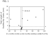
- FIG. 1 is a view illustrating the relation between the value of D and the total length of ductility-dip cracks (mm) in the present examples.
- FIG. 1 was prepared using the value of D and the total length of ductility-dip cracks (mm) with respect to examples which satisfied the chemical composition described above among examples that are described later. Note that, the total length of ductility-dip cracks (mm) was determined by a method to be described later. Further, in each of the examples shown in FIG. 1 , the occurrence of liquation cracking was not confirmed and each example had excellent corrosion resistance.
- the alloy material in an alloy material satisfying the chemical composition described above, if D is made to fall within the range of more than 0.0 to less than 6.5, the alloy material will have excellent corrosion resistance, and in addition, the occurrence of both liquation cracking and ductility-dip cracks can be suppressed.
- a Ni-Cr-Fe alloy material according to the present embodiment contains the chemical composition described above, and in addition, D is made to fall within the range of more than 0.0 to less than 6.5.
- the Ni-Cr-Fe alloy material according to the present embodiment can achieve both excellent corrosion resistance and excellent weldability.
- the gist of the Ni-Cr-Fe alloy material according to the present embodiment which has been completed based on the findings described above, is as follows.
- the gist of the Ni-Cr-Fe alloy material according to the present embodiment can also be described as follows.
- Ni-Cr-Fe alloy material according to the present embodiment is described in detail. Note that, the symbol “%" in relation to an element means mass percent unless otherwise stated.
- the chemical composition of the Ni-Cr-Fe alloy material according to the present embodiment contains the following elements.
- Silicon (Si) deoxidizes the alloy. If the content of Si is too low, the aforementioned advantageous effect will not be sufficiently obtained even if the contents of other elements are within the range of the present embodiment. On the other hand, if the content of Si is too high, even if the contents of other elements are within the range of the present embodiment, inclusions will be easily formed and the corrosion resistance of the alloy material will decrease. Therefore, the content of Si is to be 0.05 to 0.50%. A preferable lower limit of the content of Si is 0.07%, more preferably is 0.10%, and further preferably is 0.12%. A preferable upper limit of the content of Si is 0.35%, more preferably is 0.30%, and further preferably is 0.25%.
- Manganese (Mn) deoxidizes the alloy. Mn is also an austenite forming element, and stabilizes the austenite in the alloy material. If the content of Mn is too low, the aforementioned advantageous effects will not be sufficiently obtained even if the contents of other elements are within the range of the present embodiment. On the other hand, if the content of Mn is too high, even if the contents of other elements are within the range of the present embodiment, inclusions will be easily formed and the corrosion resistance of the alloy material will decrease. Therefore, the content of Mn is to be 0.10 to 1.50%. A preferable lower limit of the content of Mn is 0.20%, more preferably is 0.30%, and further preferably is 0.40%. A preferable upper limit of the content of Mn is 1.40%, more preferably is 1.30%, and further preferably is 1.20%.
- Phosphorus (P) is an impurity which is unavoidably contained. That is, the lower limit of the content of P is more than 0%. P segregates to grain boundaries. Therefore, if the content of P is too high, even if the contents of other elements are within the range of the present embodiment, the cracking susceptibility of the alloy material will increase and the weldability of the alloy material will decrease. Therefore, the content of P is to be 0.050% or less.
- a preferable upper limit of the content of P is 0.045%, more preferably is 0.040%, and further preferably is 0.030%.
- the content of P is preferably as low as possible. However, extremely reducing the content of P will significantly increase the production cost. Therefore, when industrial manufacturing is taken into consideration, a preferable lower limit of the content of P is 0.001%, more preferably is 0.002%, further preferably is 0.003%, and further preferably is 0.005%.
- Sulfur (S) is an impurity which is unavoidably contained. That is, the lower limit of the content of S is more than 0%. S segregates to grain boundaries. Therefore, if the content of S is too high, the cracking susceptibility of the alloy material will increase even if the contents of other elements are within the range of the present embodiment. In this case, in addition, inclusions will be easily formed and the corrosion resistance of the alloy material will decrease. Therefore, the content of S is to be 0.0200% or less.
- a preferable upper limit of the content of S is 0.0100%, more preferably is 0.0050%, and further preferably is 0.0030%.
- the content of S is preferably as low as possible. However, extremely reducing the content of S will significantly increase the production cost. Therefore, when industrial manufacturing is taken into consideration, a preferable lower limit of the content of S is 0.0001%, and more preferably is 0.0003%.
- Nickel (Ni) is an austenite forming element, and stabilizes the austenite in the alloy material. Ni also increases the corrosion resistance of the alloy material. If the content of Ni is too low, the aforementioned advantageous effects will not be sufficiently obtained even if the contents of other elements are within the range of the present embodiment. On the other hand, if the content of Ni is too high, the production cost will significantly increase even if the contents of other elements are within the range of the present embodiment. Furthermore, if the content of Ni is too high, in some cases the weldability of the alloy material will decrease. Therefore, the content of Ni is to be 29.0 to 40.0%. A preferable lower limit of the content of Ni is 29.5%, and more preferably is 30.0%. A preferable upper limit of the content of Ni is 39.0%, and more preferably is 38.0%.
- Chromium (Cr) increases the corrosion resistance of the alloy material.
- Cr increases the weldability of the alloy material. If the content of Cr is too low, the aforementioned advantageous effects will not be sufficiently obtained even if the contents of other elements are within the range of the present embodiment. On the other hand, if the content of Cr is too high, even if the contents of other elements are within the range of the present embodiment, intermetallic compounds typified by the ⁇ phase will be easily formed, and the corrosion resistance of the alloy material will, on the contrary, decrease. Furthermore, if the content of Cr is too high, in some cases the weldability of the alloy material will decrease. Therefore, the content of Cr is to be 24.00 to 30.00%. A preferable lower limit of the content of Cr is 24.50%, and more preferably is 25.00%. A preferable upper limit of the content of Cr is 29.00%, and more preferably is 28.00%.
- Molybdenum (Mo) increases the corrosion resistance of the alloy material. If the content of Mo is too low, the aforementioned advantageous effect will not be sufficiently obtained even if the contents of other elements are within the range of the present embodiment. On the other hand, if the content of Mo is too high, even if the contents of other elements are within the range of the present embodiment, intermetallic compounds typified by the ⁇ phase will be easily formed, and the corrosion resistance of the alloy material will, on the contrary, decrease. Furthermore, if the content of Mo is too high, in some cases the weldability of the alloy material will decrease. Therefore, the content of Mo is to be 5.0 to 7.5%. A preferable lower limit of the content of Mo is 5.1%, more preferably is 5.3%, and further preferably is 5.5%. A preferable upper limit of the content of Mo is 7.4%, more preferably is 7.2%, and further preferably is 7.0%.
- N Nitrogen
- the content of N is to be 0.20 to 0.40%.
- a preferable lower limit of the content of N is 0.21%, more preferably is 0.22%, and further preferably is 0.23%.
- a preferable upper limit of the content of N is 0.39%, more preferably is 0.37%, and further preferably is 0.36%.
- Aluminum (Al) is an impurity which is contained in the alloy material and which deoxidizes the alloy. That is, the lower limit of the content of Al is more than 0%. If the content of Al is too high, even if the contents of other elements are within the range of the present embodiment, Al oxides will excessively form and the corrosion resistance of the alloy material will decrease. Therefore, the content of Al is to be 0.50% or less. A preferable upper limit of the content of Al is 0.45%, more preferably is 0.40%, and further preferably is 0.35%. However, extremely reducing the content of Al will significantly increase the production cost. Therefore, when industrial manufacturing is taken into consideration, a preferable lower limit of the content of Al is 0.01%, more preferably is 0.03%, and further preferably is 0.05%. Note that, in the present description, the term "content of Al” means the “total Al” content, that is, the T-Al content.
- Ca Calcium (Ca) fixes S in the alloy material as a sulfide to make S harmless, and thereby suppresses ductility-dip cracks in the alloy material and increases the weldability of the alloy material. If the content of Ca is too low, the aforementioned advantageous effect will not be sufficiently obtained even if the contents of other elements are within the range of the present embodiment. On the other hand, if the content of Ca is too high, even if the contents of other elements are within the range of the present embodiment, coarse oxides will be formed in the alloy material, which will promote the occurrence of ductility-dip cracks in the alloy material, and the weldability of the alloy material will, on the contrary, decrease. Therefore, the content of Ca is to be 0.0002 to 0.0040%.
- a preferable lower limit of the content of Ca is 0.0003%, more preferably is 0.0005%, further preferably is 0.0008%, and further preferably is 0.0010%.
- a preferable upper limit of the content of Ca is 0.0035%, and more preferably is 0.0030%.
- B Boron
- B strengthens grain boundaries at high temperatures, thereby suppressing liquation cracking of the alloy material and increasing the weldability of the alloy material. If the content of B is too low, the aforementioned advantageous effect will not be sufficiently obtained even if the contents of other elements are within the range of the present embodiment. On the other hand, if the content of B is too high, B will segregate to grain boundaries, which will promote liquation cracking of the alloy material, and the weldability of the alloy material will, on the contrary, decrease. Therefore, the content of B is to be 0.0001 to 0.0050%.
- a preferable lower limit of the content of B is 0.0003%, more preferably is 0.0005%, further preferably is 0.0008%, and further preferably is 0.0010%.
- a preferable upper limit of the content of B is 0.0045%, more preferably is 0.0040%, and further preferably is 0.0035%.
- the balance of the chemical composition of the Ni-Cr-Fe alloy material according to the present embodiment is Fe and impurities.
- impurities means substances which are mixed in from ore and scrap as the raw material or from the production environment or the like when industrially producing the Ni-Cr-Fe alloy material, and which are permitted within a range that does not have a noticeable adverse effect on the operational advantages of the Ni-Cr-Fe alloy material according to the present embodiment.
- the chemical composition of the Ni-Cr-Fe alloy material according to the present embodiment may further contain one or more elements selected from the group consisting of Cu, W, Sn, and Co in lieu of a part of Fe. Each of these elements increases the corrosion resistance of the alloy material.
- Copper (Cu) is an optional element, and does not have to be contained. That is, the content of Cu may be 0%. When contained, Cu increases the corrosion resistance of the alloy material. If even a small amount of Cu is contained, the aforementioned advantageous effect will be obtained to a certain extent. However, if the content of Cu is too high, the hot workability of the alloy material will decrease even if the contents of other elements are within the range of the present embodiment. Therefore, the content of Cu is to be 0 to 0.40%, and the content of Cu in a case where Cu is contained is to be 0.40% or less.
- a preferable lower limit of the content of Cu is more than 0%, more preferably is 0.01%, further preferably is 0.02%, and further preferably is 0.04%.
- a preferable upper limit of the content of Cu is 0.38%, more preferably is 0.35%, and further preferably is 0.30%.
- Tungsten (W) is an optional element, and does not have to be contained. That is, the content of W may be 0%. When contained, W increases the corrosion resistance of the alloy material. W also increases the strength of the alloy material by solid-solution strengthening. If even a small amount of W is contained, the aforementioned advantageous effects will be obtained to a certain extent. However, if the content of W is too high, the hot workability of the alloy material will decrease even if the contents of other elements are within the range of the present embodiment. Therefore, the content of W is to be 0 to 1.00%, and the content of W in a case where W is contained is to be 1.00% or less.
- a preferable lower limit of the content of W is more than 0%, more preferably is 0.01%, further preferably is 0.03%, and further preferably is 0.05%.
- a preferable upper limit of the content of W is 0.95%, more preferably is 0.90%, and further preferably is 0.85%.
- Tin (Sn) is an optional element, and does not have to be contained. That is, the content of Sn may be 0%. When contained, Sn increases the corrosion resistance of the alloy material. If even a small amount of Sn is contained, the aforementioned advantageous effect will be obtained to a certain extent. However, if the content of Sn is too high, the hot workability of the alloy material will decrease even if the contents of other elements are within the range of the present embodiment. Therefore, the content of Sn is to be 0 to 0.50%, and the content of Sn in a case where Sn is contained is to be 0.50% or less.
- a preferable lower limit of the content of Sn is more than 0%, more preferably is 0.01%, further preferably is 0.02%, and further preferably is 0.03%.
- a preferable upper limit of the content of Sn is 0.45%, more preferably is 0.40%, and further preferably is 0.35%.
- Co Co
- the content of Co may be 0%.
- Co increases the corrosion resistance of the alloy material. If even a small amount of Co is contained, the aforementioned advantageous effect will be obtained to a certain extent. However, if the content of Co is too high, the production cost will increase extremely even if the contents of other elements are within the range of the present embodiment. Therefore, the content of Co is to be 0 to 0.50%, and the content of Co in a case where Co is contained is to be 0.50% or less.
- a preferable lower limit of the content of Co is more than 0%, more preferably is 0.01%, further preferably is 0.03%, and further preferably is 0.05%.
- a preferable upper limit of the content of Co is 0.45%, more preferably is 0.40%, and further preferably is 0.35%.
- the chemical composition of the Ni-Cr-Fe alloy material according to the present embodiment may further contain one or more elements selected from the group consisting of V, Nb, Ti, Zr, Hf, and Ta in lieu of a part of Fe. Each of these elements increases the strength of the alloy material.
- V 0.50% or less
- Vanadium (V) is an optional element, and does not have to be contained. That is, the content of V may be 0%. When contained, V forms carbo-nitrides and the like with C and N, thereby increasing the strength of the alloy material. If even a small amount of V is contained, the aforementioned advantageous effect will be obtained to a certain extent. However, if the content of V is too high, even if the contents of other elements are within the range of the present embodiment, the strength will become too high and the occurrence of ductility-dip cracks will be promoted in the alloy material, which will cause the weldability of the alloy material to decrease.
- the content of V is to be 0 to 0.50%, and the content of V in a case where V is contained is to be 0.50% or less.
- a preferable lower limit of the content of V is more than 0%, more preferably is 0.01%, further preferably is 0.03%, and further preferably is 0.05%.
- a preferable upper limit of the content of V is 0.45%, more preferably is 0.40%, and further preferably is 0.35%.
- Nb 0.50% or less
- Niobium (Nb) is an optional element, and does not have to be contained. That is, the content of Nb may be 0%. When contained, Nb forms carbo-nitrides and the like with C and N, thereby increasing the strength of the alloy material. If even a small amount of Nb is contained, the aforementioned advantageous effect will be obtained to a certain extent. However, if the content of Nb is too high, even if the contents of other elements are within the range of the present embodiment, the strength will become too high and the occurrence of ductility-dip cracks will be promoted in the alloy material, which will cause the weldability of the alloy material to decrease.
- the content of Nb is to be 0 to 0.50%, and the content of Nb in a case where Nb is contained is to be 0.50% or less.
- a preferable lower limit of the content of Nb is more than 0%, more preferably is 0.01%, further preferably is 0.03%, and further preferably is 0.05%.
- a preferable upper limit of the content of Nb is 0.45%, more preferably is 0.40%, and further preferably is 0.35%.
- Titanium (Ti) is an optional element, and does not have to be contained. That is, the content of Ti may be 0%. When contained, Ti forms carbo-nitrides and the like with C and N, thereby increasing the strength of the alloy material. If even a small amount of Ti is contained, the aforementioned advantageous effect will be obtained to a certain extent. However, if the content of Ti is too high, even if the contents of other elements are within the range of the present embodiment, the strength will become too high and the occurrence of ductility-dip cracks will be promoted in the alloy material, which will cause the weldability of the alloy material to decrease.
- the content of Ti is to be 0 to 0.50%, and the content of Ti in a case where Ti is contained is to be 0.50% or less.
- a preferable lower limit of the content of Ti is more than 0%, more preferably is 0.01%, further preferably is 0.03%, and further preferably is 0.05%.
- a preferable upper limit of the content of Ti is 0.45%, more preferably is 0.40%, and further preferably is 0.35%.
- Zirconium (Zr) is an optional element, and does not have to be contained. That is, the content of Zr may be 0%. When contained, Zr forms carbo-nitrides, thereby increasing the strength of the alloy material. If even a small amount of Zr is contained, the aforementioned advantageous effect will be obtained to a certain extent. However, if the content of Zr is too high, even if the contents of other elements are within the range of the present embodiment, the strength will become too high and the occurrence of ductility-dip cracks will be promoted in the alloy material, which will cause the weldability of the alloy material to decrease.
- the content of Zr is to be 0 to 0.200%, and the content of Zr in a case where Zr is contained is to be 0.200% or less.
- a preferable lower limit of the content of Zr is more than 0%, more preferably is 0.001%, further preferably is 0.002%, further preferably is 0.003%, and further preferably is 0.005%.
- a preferable upper limit of the content of Zr is 0.180%, more preferably is 0.150%, and further preferably is 0.120%.
- Hafnium (Hf) is an optional element, and does not have to be contained. That is, the content of Hf may be 0%. When contained, Hf forms carbo-nitrides, thereby increasing the strength of the alloy material. If even a small amount of Hf is contained, the aforementioned advantageous effect will be obtained to a certain extent. However, if the content of Hf is too high, even if the contents of other elements are within the range of the present embodiment, the strength will become too high and the occurrence of ductility-dip cracks will be promoted in the alloy material, which will cause the weldability of the alloy material to decrease.
- the content of Hf is to be 0 to 0.200%, and the content of Hf in a case where Hf is contained is to be 0.200% or less.
- a preferable lower limit of the content of Hf is more than 0%, more preferably is 0.001%, further preferably is 0.002%, further preferably is 0.003%, and further preferably is 0.005%.
- a preferable upper limit of the content of Hf is 0.180%, more preferably is 0.150%, and further preferably is 0.120%.
- Ta 0.50% or less
- Tantalum (Ta) is an optional element, and does not have to be contained. That is, the content of Ta may be 0%. When contained, Ta forms carbo-nitrides, thereby increasing the strength of the alloy material. If even a small amount of Ta is contained, the aforementioned advantageous effect will be obtained to a certain extent. However, if the content of Ta is too high, even if the contents of other elements are within the range of the present embodiment, the strength will become too high and the occurrence of ductility-dip cracks will be promoted in the alloy material, which will cause the weldability of the alloy material to decrease. Therefore, the content of Ta is to be 0 to 0.50%, and the content of Ta in a case where Ta is contained is to be 0.50% or less.
- a preferable lower limit of the content of Ta is more than 0%, more preferably is 0.01%, further preferably is 0.03%, and further preferably is 0.05%.
- a preferable upper limit of the content of Ta is 0.45%, more preferably is 0.40%, and further preferably is 0.35%.
- the chemical composition of the Ni-Cr-Fe alloy material according to the present embodiment may further contain rare earth metal in lieu of a part of Fe.
- Rare earth metal 0.0030% or less
- Rare earth metal is an optional element, and does not have to be contained. That is, the content of REM may be 0%. When contained, REM fixes S in the alloy material as a sulfide to make S harmless, thereby increasing the hot workability of the alloy material. If even a small amount of REM is contained, the aforementioned advantageous effect will be obtained to a certain extent. However, if the content of REM is too high, even if the contents of other elements are within the range of the present embodiment, coarse oxides will be formed in the alloy material, and the hot workability of the alloy material will, on the contrary, decrease.
- REM Rare earth metal
- the content of REM is to be 0 to 0.0030%, and the content of REM in a case where REM is contained is to be 0.0030% or less.
- a preferable lower limit of the content of REM is more than 0%, more preferably is 0.0001%, further preferably is 0.0005%, further preferably is 0.0008%, and further preferably is 0.0010%.
- a preferable upper limit of the content of REM is 0.0025%, and more preferably is 0.0020%.
- the term "REM” means one or more elements selected from the group consisting of scandium (Sc) which is the element with atomic number 21, yttrium (Y) which is the element with atomic number 39, and the elements from lanthanum (La) with atomic number 57 to lutetium (Lu) with atomic number 71 that are lanthanoids. Further, in the present description, the term “content of REM” means the total content of these elements.
- Ni-Cr-Fe alloy material contains the chemical composition described above and, in addition, satisfies the following Formula (1). 0.0 ⁇ 8.5 ⁇ Mn+19.5 ⁇ Ni-12.43 ⁇ Cr-42.4 ⁇ Mo-10250 ⁇ Ca+1250 ⁇ B-74.3776 ⁇ 6.5 where, a content of a corresponding element in mass% is substituted for each symbol of an element in Formula (1).
- D is 0.0 or less, although the occurrence of liquation cracking can be suppressed, the occurrence of ductility-dip cracks cannot be suppressed.
- D is 6.5 or more, although the occurrence of liquation cracking can be suppressed, the occurrence of ductility-dip cracks cannot be suppressed.
- D is made to fall within the range of more than 0.0 to less than 6.5.
- the Ni-Cr-Fe alloy material according to the present embodiment can achieve both excellent corrosion resistance and excellent weldability.
- a preferable lower limit of D is 0.1, more preferably is 0.3, and further preferably is 0.5.
- a preferable upper limit of D is 6.4, more preferably is 6.2, further preferably is 6.0, and further preferably is 5.5.
- the Ni-Cr-Fe alloy material according to the present embodiment contains the chemical composition described above and, in addition, satisfies Formula (1). As a result, the Ni-Cr-Fe alloy material according to the present embodiment has excellent corrosion resistance.
- the corrosion resistance of the alloy material in the present embodiment can be evaluated by a four-point bending test. Specifically, a test specimen is prepared from the Ni-Cr-Fe alloy material according to the present embodiment. If the alloy material is an alloy plate, the test specimen is to be prepared from a central portion of the thickness. If the alloy material is an alloy pipe, the test specimen is to be prepared from a central portion of the wall thickness.
- the test specimen has a thickness of 2 mm, a width of 10 mm, and a length of 75 mm.
- the longitudinal direction of the test specimen is to be parallel to the rolling direction of the alloy material.
- test solution A 25% by mass sodium chloride aqueous solution is employed as the test solution.
- stress is applied to the test specimen by four-point bending. The applied stress is controlled by a strain gauge to make the strain 0.2%.
- the test specimen to which stress has been applied is enclosed in an autoclave together with the test jig.
- the test solution is poured into the autoclave so as to leave a vapor phase portion, and the autoclave is sealed to thereby form a test bath.
- H 2 S gas at 1 atm is pressurized into the autoclave, and the test bath is stirred to saturate the test bath with H 2 S gas.
- the test bath is stirred at 216°C for 240 hours.
- a crack is not confirmed after 240 hours elapses in the aforementioned four-point bending test, it is determined that the alloy material has excellent corrosion resistance.
- the phrase "a crack is not confirmed” means that a crack is not confirmed in a case where the test specimen after the test is observed with the naked eye.
- the Ni-Cr-Fe alloy material according to the present embodiment contains the chemical composition described above and, in addition, satisfies Formula (1).
- the Ni-Cr-Fe alloy material according to the present embodiment not only has excellent corrosion resistance, but also has excellent weldability.
- the phrase "has excellent weldability" means that the occurrence of liquation cracking and the occurrence of ductility-dip cracks can both be suppressed.
- the weldability of the Ni-Cr-Fe alloy material according to the present embodiment can be evaluated by a longitudinal Varestraint test which is described hereunder.
- a test specimen is prepared from the Ni-Cr-Fe alloy material according to the present embodiment. If the alloy material is an alloy plate, the test specimen is to be prepared from a central portion of the thickness. If the alloy material is an alloy pipe, the test specimen is to be prepared from a central portion of the wall thickness. Regarding the size of the test specimen, for example, the test specimen has a thickness of 12 mm, a width of 50 mm, and a length of 300 mm. Note that, the longitudinal direction of the test specimen is to be parallel to the rolling direction of the alloy material.
- GTAW Gas Tungsten Arc Welding
- a region of the test specimen where the crack has occurred is polished by wet buffing and thereafter is observed using an optical microscope to identify whether the crack is a liquation crack or a ductility-dip crack.
- the magnification that is used in the observation by optical microscope is not particularly limited as long as the entire crack can be observed.
- those skilled in the art are capable of identifying liquation cracks and ductility-dip cracks.
- a weld crack that occurs in the HAZ away from the fusion line can be determined to be a ductility-dip crack.
- a crack in the HAZ near the fusion line can be determined to be a liquation crack. In this way, whether a weld crack which occurred in the test specimen is a liquation crack or a ductility-dip crack is identified by observation with an optical microscope.
- the total length of ductility-dip cracks is determined.
- the method of determining the total length of ductility-dip cracks is not particularly limited. For example, using a photograph generated by optical microscopy, the crack length can be determined by measurement with a ruler and comparison with a scale bar. In addition, for example, the crack length can be determined by image analysis of a photograph generated by optical microscopy.
- the shape of the Ni-Cr-Fe alloy material according to the present embodiment is not particularly limited.
- the shape of the alloy material for example, may be a pipe shape, may be a bar shape, may be a linear shape, may be a thick plate shape, may be a sheet shape, or may be a foil shape.
- the alloy material is a pipe shape, preferably the alloy material is a seamless alloy pipe.
- Ni-Cr-Fe alloy material according to the present embodiment are not particularly limited.
- the Ni-Cr-Fe alloy material according to the present embodiment can be used in equipment relating to the petroleum industry, the gas industry, the petrochemical industry, and the chemical industry.
- the Ni-Cr-Fe alloy material according to the present embodiment is suitable for use in primary processing equipment for petroleum and gas and equipment of chemical plants and the like.
- the method for producing a seamless alloy pipe includes a process of preparing a starting material (starting material preparation process), a process of producing a hollow shell from the starting material (hot working process), and a process of performing a solution heat treatment (solution heat treatment process).
- starting material preparation process a process of preparing a starting material
- hot working process a process of producing a hollow shell from the starting material
- solution heat treatment process a process of performing a solution heat treatment
- Ni-Cr-Fe alloy containing the chemical composition described above is melted.
- the Ni-Cr-Fe alloy may be melted by an electric furnace, may be melted by an Ar-O 2 mixed gas bottom-blowing decarburization furnace (AOD furnace), or may be melted by a vacuum-oxygen decarburization furnace (VOD furnace).
- AOD furnace Ar-O 2 mixed gas bottom-blowing decarburization furnace
- VOD furnace vacuum-oxygen decarburization furnace
- the melted Ni-Cr-Fe alloy may be made into an ingot by an ingot-making process, or may be made into a slab, a bloom, or a billet by a continuous casting process. As necessary, the slab, the bloom, or the ingot may be subjected to blooming to produce a billet.
- the starting material (a slab, a bloom, or a billet) is produced by the above process.
- the prepared starting material is subjected to hot working to produce an intermediate alloy material (hollow shell).
- the method of hot working is not particularly limited, and it suffices to use a well-known method. That is, in the present embodiment, the hot working may be hot rolling, may be hot extrusion, or may be hot forging. In the hot working, the heating temperature of the starting material is, for example, 1100 to 1300°C.
- the Mannesmann process may be performed as hot working to produce a hollow shell.
- the piercing ratio is, for example, 1.0 to 4.0.
- the Ugine-Sejournet process or the Ehrhardt push bench process (that is, hot extrusion) may be performed as hot working to produce a hollow shell.
- the produced hollow shell may be subjected to hot rolling using a mandrel mill, a stretch reducing mill, a sizing mill or the like.
- the produced intermediate alloy material (hollow shell) is subjected to a solution heat treatment.
- the method for performing the solution heat treatment is not particularly limited, and it suffices to use a well-known method.
- the hollow shell is loaded into a heat treatment furnace, and after being held at a desired temperature, is rapidly cooled.
- the temperature at which the solution heat treatment is performed (the solution heat treatment temperature) means the temperature (°C) of the heat treatment furnace used to perform the solution heat treatment.
- the time for which the solution heat treatment is performed means the time for which the hollow shell is held at the solution heat treatment temperature.
- the solution heat treatment temperature in the solution heat treatment process according to the present embodiment is set to 1100 to 1300°C. If the solution heat treatment temperature is too low, precipitates (for example, the ⁇ phase that is an intermetallic compound or the like) may sometimes remain in the hollow shell after the solution heat treatment. In this case, the corrosion resistance of the produced Ni-Cr-Fe alloy material may decrease. On the other hand, if the solution heat treatment temperature is too high, the advantageous effect of the solution heat treatment will be saturated. Therefore, in the present embodiment, preferably the solution heat treatment temperature in the solution heat treatment process is set to 1100 to 1300°C.
- the solution heat treatment time is not particularly limited, and it suffices that the solution heat treatment time is in accordance with a well-known condition.
- the solution heat treatment time is, for example, 5 to 180 minutes.
- the rapid cooling method is, for example, water-cooling.
- the Ni-Cr-Fe alloy material according to the present embodiment can be produced by the production method described above.
- the Ni-Cr-Fe alloy material according to the present embodiment may be subjected to other processes.
- the intermediate alloy material may be subjected to cold working.
- the cold working may be cold rolling or may be cold drawing.
- the intermediate alloy material can be processed into desired dimensions.
- the produced Ni-Cr-Fe alloy material may be further subjected to cold working. In this case, the strength of the Ni-Cr-Fe alloy material will increase.
- the Ni-Cr-Fe alloy material according to the present embodiment may be another shape, such as a plate shape.
- a method for producing the Ni-Cr-Fe alloy material that is another shape, such as a plate shape also includes, for example, a starting material preparation process, a hot working process, and a solution heat treatment process, similarly to the production method described above.
- the production method described above is an example, and the Ni-Cr-Fe alloy material according to the present embodiment may also be produced by a different production method.
- the alloy of each test number was used to produce a 50 kg ingot by vacuum melting. After the ingot of each symbol was heated at 1200°C for 24 hours, each ingot was subjected to hot forging to produce a rectangular bar having a cross section of 50 mm ⁇ 50 mm. Each obtained rectangular bar was heated at 1200°C for one hour, and thereafter was subjected to hot rolling to produce a plate with a thickness of 30 mm. After the hot rolling, the plate was subjected to cold rolling to produce a plate (alloy plate) with a thickness of 15 mm. The obtained alloy plate of each test number was subjected to a solution heat treatment in which the alloy plate was heated at 1200°C for one hour, and thereafter was water-cooled. An alloy plate of each test number was produced by the above process.
- the alloy plate of each test number was subjected to a corrosion resistance test and a weldability test which are described hereunder.
- the alloy plate of each test number was subjected to a four-point bending test by the method described above, and the corrosion resistance was evaluated. Specifically, a test specimen having a thickness of 2 mm, a width of 10 mm, and a length of 75 mm was prepared from a central portion of the thickness of the alloy plate of each test number. The longitudinal direction of the test specimen corresponded to the rolling direction of the alloy plate. A 25% by mass sodium chloride aqueous solution was employed as the test solution. In accordance with ASTM G39-99 (2011), the test specimen loaded with stress corresponding to a strain of 0.2% by four-point bending was enclosed in an autoclave together with the test jig.
- test solution was poured into the autoclave so as to leave a vapor phase portion, and the autoclave was sealed to thereby form a test bath.
- H 2 S gas at 1 atm was pressurized into the autoclave, and the test bath was stirred to saturate the test bath with the H 2 S gas.
- the test bath was stirred at 216°C for 240 hours. If the result of the four-point bending test performed under the aforementioned conditions was that a crack was not confirmed in the test specimen after 240 hours elapsed, it was determined that the alloy plate of the relevant test number had excellent corrosion resistance (indicated by "E" (Excellent) in the column "Corrosion Resistance” in Table 3).
- test numbers that were determined to have excellent corrosion resistance among all the test numbers was evaluated. That is, the weldability of test numbers which were determined as not having excellent corrosion resistance was not evaluated (indicated by "-" (no evaluation) in the column “Liquation Cracking” in Table 3). Specifically, the alloy plates of test numbers which had been evaluated as having excellent corrosion resistance were subjected to a longitudinal Varestraint test by the method described above, and the weldability was evaluated.
- a test specimen having a thickness of 12 mm, a width of 50 mm, and a length of 300 mm was prepared from a central portion of the thickness of the alloy plate of each test number that had been evaluated as having excellent corrosion resistance.
- the longitudinal direction of the test specimen corresponded to the rolling direction of the alloy plate.
- One end of the test specimen in the longitudinal direction was fixed, and bead-on-plate welding was performed by GTAW in the longitudinal direction of the test specimen from the fixed end.
- GTAW in the longitudinal direction of the test specimen from the fixed end.
- stress was applied to the unfixed end in the longitudinal direction of the test specimen to deform the test specimen along the curvature of a bending block. In this way, a crack was generated in the test specimen.
- the welding conditions were set as follows: a welding current of 200 A, a welding voltage of 12 V, a welding speed of 15 cm/min, and a load strain of 2%.
- a region of the test specimen where a crack had occurred was polished by wet buffing and thereafter was observed using an optical microscope to identify whether the crack was a liquation crack or a ductility-dip crack. If the identified crack was a liquation crack, it was determined that a liquation crack was confirmed in the alloy plate of the relevant test number (indicated by "NA” (Not Acceptable) in the column “Liquation Cracking” in Table 3). If the identified crack was a ductility-dip crack, it was determined that a liquation crack was not confirmed in the alloy plate of the relevant test number (indicated by "E” (Excellent) in the column “Liquation Cracking” in Table 3).
- the total length of ductility-dip cracks was determined.
- the total length of ductility-dip cracks was determined by using a ruler to measure the length of ductility-dip cracks from a photograph generated by optical microscopy, and performing a comparison with a scale bar.
- the obtained length (mm) of ductility-dip cracks is shown in Table 3.
- the alloy plates of Test Nos. 24 and 25 did not contain Ca and B, and in addition, in these alloy plates D was 6.5 or more. As a result, in these alloy plates the total length of ductility-dip cracks was 4.0 mm or more. That is, these alloy plates did not have excellent weldability.
Landscapes
- Chemical & Material Sciences (AREA)
- Engineering & Computer Science (AREA)
- Materials Engineering (AREA)
- Mechanical Engineering (AREA)
- Metallurgy (AREA)
- Organic Chemistry (AREA)
- Physics & Mathematics (AREA)
- Thermal Sciences (AREA)
- Crystallography & Structural Chemistry (AREA)
- Manufacturing & Machinery (AREA)
- Heat Treatment Of Steel (AREA)
Abstract
Description
- The present disclosure relates to a Ni-Cr-Fe alloy material.
- Alloy materials that are used in primary processing equipment for petroleum and gas and equipment of chemical plants and the like come into contact with process fluids containing sulfides and/or chlorides. Therefore, the alloy materials used in these kinds of equipment are required to have excellent corrosion resistance. Examples of such materials which are required to have excellent corrosion resistance include 18-8 stainless steel materials such as SUS304H, SUS316H, SUS321H, and SUS347H, and Ni-Cr-Fe alloy materials represented by Alloy 800H, which is defined as NCF800H by the JIS Standard. Ni-Cr-Fe alloy materials have excellent corrosion resistance in comparison to 18-8 stainless steel materials. Ni-Cr-Fe alloy materials are also more excellent in economic efficiency in comparison to Ni-base alloy materials represented by Alloy 617. Therefore, in some cases Ni-Cr-Fe alloy materials are used as alloy materials that have excellent corrosion resistance.
-
Japanese Patent Application Publication No. 2-217445 WO2015/072458 (Patent Literature 2) each propose an alloy material that has excellent corrosion resistance. - Patent Literature 1 discloses an alloy material which is an Fe-Cr-Ni alloy that consists essentially of Ni: 27 to 32%, Cr: 24 to 28%, Cu: 1.25 to 3.0%, Mo: 1.0 to 3.0%, Si: 1.5 to 2.75%, and Mn: 1.0 to 2.0%, and the following elements whose amounts are controlled as follows: N: 0.015% or less, B: 0.10% or less, V: 0.10% or less, C: 0.10% or less, Al: 0.30% or less, P: 0.03% or less, and S: 0.02% or less, with the balance being Fe and impurities. It is described in Patent Literature 1 that this alloy material has high strength, galling resistance, and corrosion resistance under stress.
- Patent Literature 2 discloses an alloy material that is a Ni-Cr alloy material containing a chemical composition consisting of, by mass%, Si: 0.01 to 0.5%, Mn: 0.01 to less than 1.0%, Cu: 0.01 to less than 1.0%, Ni: 48 to less than 55%, Cr: 22 to 28%, Mo: 5.6 to less than 7.0%, N: 0.04 to 0.16%, sol. Al: 0.03 to 0.20%, REM: 0.01 to 0.074%, W: 0 to less than 8.0%, Co: 0 to 2.0%, one or more of Ca and Mg: 0.0003 to 0.01% in total, and one or more of Ti, Nb, Zr, and V: 0 to 0.5% in total, with the balance being Fe and impurities, with C, P, S, and O in the impurities being as follows: C: 0.03% or less, P: 0.03% or less, S: 0.001% or less, and O: 0.01% or less, and in which a dislocation density ρ satisfies the formula (7.0×10¹⁵ ≤ ρ ≤ 2.7×10¹⁶-2.67×10¹⁷×[REM(%)]). It is described in Patent Literature 2 that this alloy material is excellent in hot workability and toughness, and is also excellent in corrosion resistance (stress corrosion cracking resistance in environments in which the temperature is a high temperature of more than 200°C and which contain hydrogen sulfide), and has a yield strength (0.2% proof stress) of 965 MPa or more.
-
- Patent Literature 1:
Japanese Patent Application Publication No. 2-217445 - Patent Literature 2: International Application Publication No.
WO2015/072458 - As described above, alloy materials having excellent corrosion resistance are disclosed in the aforementioned Patent Literatures 1 and 2. However, a Ni-Cr-Fe alloy material having excellent corrosion resistance may also be obtained by a technique that is different from the techniques disclosed in the aforementioned Patent Literatures 1 and 2.
- In this connection, when constructing and repairing primary processing equipment for petroleum and gas and equipment of chemical plants and the like, in some cases Ni-Cr-Fe alloy materials is subjected to welding. Therefore, Ni-Cr-Fe alloy materials that are used in primary processing equipment for petroleum and gas and equipment of chemical plants and the like are required to have not only excellent corrosion resistance but also excellent weldability. Here, the term "excellent weldability" means that it is difficult for weld cracks (cracks that occur near the weld zone) to occur. On the other hand, in the aforementioned Patent Literatures 1 and 2, the weldability of the alloy materials is not investigated.
- An objective of the present disclosure is to provide a Ni-Cr-Fe alloy material that has excellent corrosion resistance and excellent weldability.
- A Ni-Cr-Fe alloy material according to the present disclosure contains a chemical composition consisting of, by mass%,
- C: 0.002 to 0.030%,
- Si: 0.05 to 0.50%,
- Mn: 0.10 to 1.50%,
- P: 0.050% or less,
- S: 0.0200% or less,
- Ni: 29.0 to 40.0%,
- Cr: 24.00 to 30.00%,
- Mo: 5.0 to 7.5%,
- N: 0.20 to 0.40%,
- Al: 0.50% or less,
- Ca: 0.0002 to 0.0040%, and
- B: 0.0001 to 0.0050%,
- with the balance being Fe and impurities,
- the chemical composition satisfying the following Formula (1):
0.0 < 8.5×Mn+19.5×Ni-12.43×Cr-42.4×Mo-10250×Ca+1250×B-74.3776 < 6.5 - where, a content of a corresponding element in mass% is substituted for each symbol of an element in Formula (1).
- A Ni-Cr-Fe alloy material according to the present disclosure contains a chemical composition containing, by mass%,
- C: 0.002 to 0.030%,
- Si: 0.05 to 0.50%,
- Mn: 0.10 to 1.50%,
- P: 0.050% or less,
- S: 0.0200% or less,
- Ni: 29.0 to 40.0%,
- Cr: 24.00 to 30.00%,
- Mo: 5.0 to 7.5%,
- N: 0.20 to 0.40%,
- Al: 0.50% or less,
- Ca: 0.0002 to 0.0040%, and
- B: 0.0001 to 0.0050%,
- Cu: 0.40% or less,
- W: 1.00% or less,
- Sn: 0.50% or less,
- Co: 0.50% or less,
- V: 0.50% or less,
- Nb: 0.50% or less,
- Ti: 0.50% or less,
- Zr: 0.200% or less,
- Hf: 0.200% or less,
- Ta: 0.50% or less, and
- rare earth metal: 0.0030% or less,
- with the balance being Fe and impurities,
- the chemical composition satisfying the following Formula (1):
0.0 < 8.5×Mn+19.5×Ni-12.43×Cr-42.4×Mo-10250×Ca+1250×B-74.3776 < 6.5 - where, a content of a corresponding element in mass% is substituted for each symbol of an element in Formula (1).
- The Ni-Cr-Fe alloy material according to the present disclosure has excellent corrosion resistance and excellent weldability.
- [
FIG. 1] FIG. 1 is a view illustrating the relation between the value of D (= 8.5×Mn+19.5×Ni-12.43×Cr-42.4×Mo-10250×Ca+1250×B-74.3776) and a total length of ductility-dip cracks (mm) in the present examples. - First, the present inventors conducted studies regarding the corrosion resistance of Ni-Cr-Fe alloy materials from the viewpoint of the chemical composition. As a result, the present inventors considered that if a Ni-Cr-Fe alloy material contains, by mass%, C: 0.002 to 0.030%, Si: 0.05 to 0.50%, Mn: 0.10 to 1.50%, P: 0.050% or less, S: 0.0200% or less, Ni: 29.0 to 40.0%, Cr: 24.00 to 30.00%, Mo: 5.0 to 7.5%, N: 0.20 to 0.40%, Al: 0.50% or less, Cu: 0 to 0.40%, W: 0 to 1.00%, Sn: 0 to 0.50%, Co: 0 to 0.50%, V: 0 to 0.50%, Nb: 0 to 0.50%, Ti: 0 to 0.50%, Zr: 0 to 0.200%, Hf: 0 to 0.200%, Ta: 0 to 0.50%, and rare earth metal: 0 to 0.0030%, there is a possibility that the corrosion resistance will be increased.
- Here, in Ni-Cr-Fe alloy materials containing the chemical composition described above, welding thereof may cause weld cracks. Specifically, it has been revealed by detailed studies conducted by the present inventors that, in a Ni-Cr-Fe alloy material containing the chemical composition described above, among the different types of weld cracks, a ductility-dip crack is liable to occur. The term "ductility-dip crack" refers to a type of weld crack in which crystal grain boundaries exposed to high temperatures due to welding undergo a decrease in ductility and consequently crack due to being unable to withstand thermal contraction caused by cooling. In other words, if the crystal grain boundaries of a Ni-Cr-Fe alloy material containing the chemical composition described above can be strengthened, there is a possibility that the occurrence of ductility-dip cracks can be suppressed.
- Therefore, the present inventors focused their attention on calcium (Ca), and conducted studies with regard to suppressing ductility-dip cracks. Specifically, when welding an alloy material containing the chemical composition described above, there is a possibility that sulfur (S) segregates to grain boundaries in a heat affected zone (hereunder, referred to as "HAZ") from welding. If S segregates to the grain boundaries, there is a possibility that the bonding strength of the grain boundaries will decrease and will crack due to being unable to withstand thermal contraction caused by cooling. The present inventors considered that it is likely that, in this way, ductility-dip cracks occur in an alloy material containing the chemical composition described above. That is, the present inventors considered that if an alloy material contains Ca in an amount of 0.0002 to 0.0040% in addition to the chemical composition described above, there is a possibility that the Ca will fix S in the alloy material as CaS, and thus ductility-dip cracks in the alloy material can be suppressed.
- On the other hand, even when alloy materials contained Ca in an amount of 0.0002 to 0.0040% in addition to the chemical composition described above, weld cracks occurred in some cases. Specifically, in alloy materials containing Ca in an amount of 0.0002 to 0.0040% in addition to the chemical composition described above, among the different types of weld cracks, in some cases liquation cracking occurred. The term "liquation cracking" refers to a type of weld crack in which cracking occurs due to localized melting that occurs in the HAZ near the fusion line.
- Therefore, the present inventors focused their attention on boron (B), and conducted studies with regard to suppressing liquation cracking. Specifically, B strengthens grain boundaries at high temperatures, and thereby suppresses liquation cracking. On the other hand, if the content of B is too high, B segregates to grain boundaries and melts in a high temperature region near the fusion line, and thereby, on the contrary, promotes liquation cracking. In other words, by containing B in an amount of 0.0001 to 0.0050% and Ca in an amount of 0.0002 to 0.0040% in addition to the chemical composition described above, there is a possibility that the occurrence of ductility-dip cracks and liquation cracking can both be suppressed, and the weldability of the alloy material can be increased.
- That is, the present inventors considered that if a Ni-Cr-Fe alloy material consists of, by mass%, C: 0.002 to 0.030%, Si: 0.05 to 0.50%, Mn: 0.10 to 1.50%, P: 0.050% or less, S: 0.0200% or less, Ni: 29.0 to 40.0%, Cr: 24.00 to 30.00%, Mo: 5.0 to 7.5%, N: 0.20 to 0.40%, Al: 0.50% or less, Ca: 0.0002 to 0.0040%, B: 0.0001 to 0.0050%, Cu: 0 to 0.40%, W: 0 to 1.00%, Sn: 0 to 0.50%, Co: 0 to 0.50%, V: 0 to 0.50%, Nb: 0 to 0.50%, Ti: 0 to 0.50%, Zr: 0 to 0.200%, Hf: 0 to 0.200%, Ta: 0 to 0.50%, and rare earth metal: 0 to 0.0030%, with the balance being Fe and impurities, there is a possibility that both corrosion resistance and weldability can be achieved.
- The present inventors produced various Ni-Cr-Fe alloy materials containing the chemical composition described above, and conducted further detailed studies on the occurrence of weld cracks. As a result, the present inventors found that in a Ni-Cr-Fe alloy material containing the chemical composition described above, by satisfying the following Formula (1), not only has the Ni-Cr-Fe alloy material excellent corrosion resistance, but furthermore, the occurrence of both ductility-dip cracks and liquation cracking can also be suppressed:
0.0 < 8.5×Mn+19.5×Ni-12.43×Cr-42.4×Mo-10250×Ca+1250×B-74.3776 < 6.5 - Let D be defined as D = 8.5×Mn+19.5×Ni-12.43×Cr-42.4×Mo-10250×Ca+1250×B-74.3776.
FIG. 1 is a view illustrating the relation between the value of D and the total length of ductility-dip cracks (mm) in the present examples.FIG. 1 was prepared using the value of D and the total length of ductility-dip cracks (mm) with respect to examples which satisfied the chemical composition described above among examples that are described later. Note that, the total length of ductility-dip cracks (mm) was determined by a method to be described later. Further, in each of the examples shown inFIG. 1 , the occurrence of liquation cracking was not confirmed and each example had excellent corrosion resistance. - Referring to
FIG. 1 , in alloy materials that satisfied the chemical composition described above, in cases where D was 0.0 or less, although the occurrence of liquation cracking could be suppressed, the total length of ductility-dip cracks was 4.0 mm or more and thus the occurrence of ductility-dip cracks could not be suppressed. Referring further toFIG. 1 , in alloy materials that satisfied the chemical composition described above, in cases where D was 6.5 or more, although the occurrence of liquation cracking could be suppressed, the total length of ductility-dip cracks was 4.0 mm or more and thus the occurrence of ductility-dip cracks could not be suppressed. That is, in an alloy material satisfying the chemical composition described above, if D is made to fall within the range of more than 0.0 to less than 6.5, the alloy material will have excellent corrosion resistance, and in addition, the occurrence of both liquation cracking and ductility-dip cracks can be suppressed. - Therefore, a Ni-Cr-Fe alloy material according to the present embodiment contains the chemical composition described above, and in addition, D is made to fall within the range of more than 0.0 to less than 6.5. As a result, the Ni-Cr-Fe alloy material according to the present embodiment can achieve both excellent corrosion resistance and excellent weldability.
- The gist of the Ni-Cr-Fe alloy material according to the present embodiment, which has been completed based on the findings described above, is as follows.
- [1] A Ni-Cr-Fe alloy material containing a chemical composition consisting of, by mass%,
- C: 0.002 to 0.030%,
- Si: 0.05 to 0.50%,
- Mn: 0.10 to 1.50%,
- P: 0.050% or less,
- S: 0.0200% or less,
- Ni: 29.0 to 40.0%,
- Cr: 24.00 to 30.00%,
- Mo: 5.0 to 7.5%,
- N: 0.20 to 0.40%,
- Al: 0.50% or less,
- Ca: 0.0002 to 0.0040%, and
- B: 0.0001 to 0.0050%,
- with the balance being Fe and impurities,
- the chemical composition satisfying the following Formula (1):
0.0 < 8.5×Mn+19.5×Ni-12.43×Cr-42.4×Mo-10250×Ca+1250×B-74.3776 < 6.5 - where, a content of a corresponding element in mass% is substituted for each symbol of an element in Formula (1).
- [2] A Ni-Cr-Fe alloy material containing a chemical composition containing, by mass%,
- C: 0.002 to 0.030%,
- Si: 0.05 to 0.50%,
- Mn: 0.10 to 1.50%,
- P: 0.050% or less,
- S: 0.0200% or less,
- Ni: 29.0 to 40.0%,
- Cr: 24.00 to 30.00%,
- Mo: 5.0 to 7.5%,
- N: 0.20 to 0.40%,
- Al: 0.50% or less,
- Ca: 0.0002 to 0.0040%, and
- B: 0.0001 to 0.0050%,
- Cu: 0.40% or less,
- W: 1.00% or less,
- Sn: 0.50% or less,
- Co: 0.50% or less,
- V: 0.50% or less,
- Nb: 0.50% or less,
- Ti: 0.50% or less,
- Zr: 0.200% or less,
- Hf: 0.200% or less,
- Ta: 0.50% or less, and
- rare earth metal: 0.0030% or less,
- with the balance being Fe and impurities,
- the chemical composition satisfying the following Formula (1):
0.0 < 8.5×Mn+19.5×Ni-12.43×Cr-42.4×Mo-10250×Ca+1250×B-74.3776 < 6.5 - where, a content of a corresponding element in mass% is substituted for each symbol of an element in Formula (1).
- [3] The Ni-Cr-Fe alloy material according to [2], wherein the chemical composition contains one or more elements selected from a group consisting of:
- Cu: 0.40% or less,
- W: 1.00% or less,
- Sn: 0.50% or less, and
- Co: 0.50% or less.
- [4] The Ni-Cr-Fe alloy material according to [2], wherein the chemical composition contains one or more elements selected from a group consisting of:
- V: 0.50% or less,
- Nb: 0.50% or less,
- Ti: 0.50% or less,
- Zr: 0.200% or less,
- Hf: 0.200% or less, and
- Ta: 0.50% or less.
- [5] The Ni-Cr-Fe alloy material according to [2], wherein the chemical composition contains:
rare earth metal: 0.0030% or less. - The gist of the Ni-Cr-Fe alloy material according to the present embodiment can also be described as follows.
- [1] A Ni-Cr-Fe alloy material consisting of, by mass%,
- C: 0.002 to 0.030%,
- Si: 0.05 to 0.50%,
- Mn: 0.10 to 1.50%,
- P: 0.050% or less,
- S: 0.0200% or less,
- Ni: 29.0 to 40.0%,
- Cr: 24.00 to 30.00%,
- Mo: 5.0 to 7.5%,
- N: 0.20 to 0.40%,
- Al: 0.50% or less,
- Ca: 0.0002 to 0.0040%,
- B: 0.0001 to 0.0050%,
- Cu: 0 to 0.40%,
- W: 0 to 1.00%,
- Sn: 0 to 0.50%,
- Co: 0 to 0.50%,
- V: 0 to 0.50%,
- Nb: 0 to 0.50%,
- Ti: 0 to 0.50%,
- Zr: 0 to 0.200%,
- Hf: 0 to 0.200%,
- Ta: 0 to 0.50%,
- rare earth metal: 0 to 0.0030%, and
- the balance: Fe and impurities,
- and satisfying the following Formula (1):
0.0 < 8.5×Mn+19.5×Ni-12.43×Cr-42.4×Mo-10250×Ca+1250×B-74.3776 < 6.5 - where, a content of a corresponding element in mass% is substituted for each symbol of an element in Formula (1).
- [2] The Ni-Cr-Fe alloy material according to [1], containing one or more elements selected from a group consisting of:
- Cu: 0.01 to 0.40%,
- W: 0.01 to 1.00%,
- Sn: 0.01 to 0.50%,
- Co: 0.01 to 0.50%,
- V: 0.01 to 0.50%,
- Nb: 0.01 to 0.50%,
- Ti: 0.01 to 0.50%,
- Zr: 0.001 to 0.200%,
- Hf: 0.001 to 0.200%,
- Ta: 0.01 to 0.50%, and
- rare earth metal: 0.0001 to 0.0030%.
- Hereunder, the Ni-Cr-Fe alloy material according to the present embodiment is described in detail. Note that, the symbol "%" in relation to an element means mass percent unless otherwise stated.
- The chemical composition of the Ni-Cr-Fe alloy material according to the present embodiment contains the following elements.
- Carbon (C) deoxidizes the alloy. C also increases the strength of the alloy material. If the content of C is too low, the aforementioned advantageous effects will not be sufficiently obtained even if the contents of other elements are within the range of the present embodiment. On the other hand, if the content of C is too high, even if the contents of other elements are within the range of the present embodiment, the heat affected zone from welding will easily become sensitized during welding. Therefore, the content of C is to be 0.002 to 0.030%. A preferable lower limit of the content of C is 0.003%, more preferably is 0.005%, and further preferably is 0.007%. A preferable upper limit of the content of C is 0.025%, more preferably is 0.023%, and further preferably is 0.020%.
- Silicon (Si) deoxidizes the alloy. If the content of Si is too low, the aforementioned advantageous effect will not be sufficiently obtained even if the contents of other elements are within the range of the present embodiment. On the other hand, if the content of Si is too high, even if the contents of other elements are within the range of the present embodiment, inclusions will be easily formed and the corrosion resistance of the alloy material will decrease. Therefore, the content of Si is to be 0.05 to 0.50%. A preferable lower limit of the content of Si is 0.07%, more preferably is 0.10%, and further preferably is 0.12%. A preferable upper limit of the content of Si is 0.35%, more preferably is 0.30%, and further preferably is 0.25%.
- Manganese (Mn) deoxidizes the alloy. Mn is also an austenite forming element, and stabilizes the austenite in the alloy material. If the content of Mn is too low, the aforementioned advantageous effects will not be sufficiently obtained even if the contents of other elements are within the range of the present embodiment. On the other hand, if the content of Mn is too high, even if the contents of other elements are within the range of the present embodiment, inclusions will be easily formed and the corrosion resistance of the alloy material will decrease. Therefore, the content of Mn is to be 0.10 to 1.50%. A preferable lower limit of the content of Mn is 0.20%, more preferably is 0.30%, and further preferably is 0.40%. A preferable upper limit of the content of Mn is 1.40%, more preferably is 1.30%, and further preferably is 1.20%.
- Phosphorus (P) is an impurity which is unavoidably contained. That is, the lower limit of the content of P is more than 0%. P segregates to grain boundaries. Therefore, if the content of P is too high, even if the contents of other elements are within the range of the present embodiment, the cracking susceptibility of the alloy material will increase and the weldability of the alloy material will decrease. Therefore, the content of P is to be 0.050% or less. A preferable upper limit of the content of P is 0.045%, more preferably is 0.040%, and further preferably is 0.030%. The content of P is preferably as low as possible. However, extremely reducing the content of P will significantly increase the production cost. Therefore, when industrial manufacturing is taken into consideration, a preferable lower limit of the content of P is 0.001%, more preferably is 0.002%, further preferably is 0.003%, and further preferably is 0.005%.
- Sulfur (S) is an impurity which is unavoidably contained. That is, the lower limit of the content of S is more than 0%. S segregates to grain boundaries. Therefore, if the content of S is too high, the cracking susceptibility of the alloy material will increase even if the contents of other elements are within the range of the present embodiment. In this case, in addition, inclusions will be easily formed and the corrosion resistance of the alloy material will decrease. Therefore, the content of S is to be 0.0200% or less. A preferable upper limit of the content of S is 0.0100%, more preferably is 0.0050%, and further preferably is 0.0030%. The content of S is preferably as low as possible. However, extremely reducing the content of S will significantly increase the production cost. Therefore, when industrial manufacturing is taken into consideration, a preferable lower limit of the content of S is 0.0001%, and more preferably is 0.0003%.
- Nickel (Ni) is an austenite forming element, and stabilizes the austenite in the alloy material. Ni also increases the corrosion resistance of the alloy material. If the content of Ni is too low, the aforementioned advantageous effects will not be sufficiently obtained even if the contents of other elements are within the range of the present embodiment. On the other hand, if the content of Ni is too high, the production cost will significantly increase even if the contents of other elements are within the range of the present embodiment. Furthermore, if the content of Ni is too high, in some cases the weldability of the alloy material will decrease. Therefore, the content of Ni is to be 29.0 to 40.0%. A preferable lower limit of the content of Ni is 29.5%, and more preferably is 30.0%. A preferable upper limit of the content of Ni is 39.0%, and more preferably is 38.0%.
- Chromium (Cr) increases the corrosion resistance of the alloy material. In addition, in some cases Cr increases the weldability of the alloy material. If the content of Cr is too low, the aforementioned advantageous effects will not be sufficiently obtained even if the contents of other elements are within the range of the present embodiment. On the other hand, if the content of Cr is too high, even if the contents of other elements are within the range of the present embodiment, intermetallic compounds typified by the σ phase will be easily formed, and the corrosion resistance of the alloy material will, on the contrary, decrease. Furthermore, if the content of Cr is too high, in some cases the weldability of the alloy material will decrease. Therefore, the content of Cr is to be 24.00 to 30.00%. A preferable lower limit of the content of Cr is 24.50%, and more preferably is 25.00%. A preferable upper limit of the content of Cr is 29.00%, and more preferably is 28.00%.
- Molybdenum (Mo) increases the corrosion resistance of the alloy material. If the content of Mo is too low, the aforementioned advantageous effect will not be sufficiently obtained even if the contents of other elements are within the range of the present embodiment. On the other hand, if the content of Mo is too high, even if the contents of other elements are within the range of the present embodiment, intermetallic compounds typified by the σ phase will be easily formed, and the corrosion resistance of the alloy material will, on the contrary, decrease. Furthermore, if the content of Mo is too high, in some cases the weldability of the alloy material will decrease. Therefore, the content of Mo is to be 5.0 to 7.5%. A preferable lower limit of the content of Mo is 5.1%, more preferably is 5.3%, and further preferably is 5.5%. A preferable upper limit of the content of Mo is 7.4%, more preferably is 7.2%, and further preferably is 7.0%.
- Nitrogen (N) dissolves in the alloy material, thereby increasing the strength of the alloy material. In some cases, N also increases the corrosion resistance of the alloy material. If the content of N is too low, the aforementioned advantageous effects will not be sufficiently obtained even if the contents of other elements are within the range of the present embodiment. On the other hand, if the content of N is too high, the weldability of the alloy material will decrease even if the contents of other elements are within the range of the present embodiment. Therefore, the content of N is to be 0.20 to 0.40%. A preferable lower limit of the content of N is 0.21%, more preferably is 0.22%, and further preferably is 0.23%. A preferable upper limit of the content of N is 0.39%, more preferably is 0.37%, and further preferably is 0.36%.
- Aluminum (Al) is an impurity which is contained in the alloy material and which deoxidizes the alloy. That is, the lower limit of the content of Al is more than 0%. If the content of Al is too high, even if the contents of other elements are within the range of the present embodiment, Al oxides will excessively form and the corrosion resistance of the alloy material will decrease. Therefore, the content of Al is to be 0.50% or less. A preferable upper limit of the content of Al is 0.45%, more preferably is 0.40%, and further preferably is 0.35%. However, extremely reducing the content of Al will significantly increase the production cost. Therefore, when industrial manufacturing is taken into consideration, a preferable lower limit of the content of Al is 0.01%, more preferably is 0.03%, and further preferably is 0.05%. Note that, in the present description, the term "content of Al" means the "total Al" content, that is, the T-Al content.
- Calcium (Ca) fixes S in the alloy material as a sulfide to make S harmless, and thereby suppresses ductility-dip cracks in the alloy material and increases the weldability of the alloy material. If the content of Ca is too low, the aforementioned advantageous effect will not be sufficiently obtained even if the contents of other elements are within the range of the present embodiment. On the other hand, if the content of Ca is too high, even if the contents of other elements are within the range of the present embodiment, coarse oxides will be formed in the alloy material, which will promote the occurrence of ductility-dip cracks in the alloy material, and the weldability of the alloy material will, on the contrary, decrease. Therefore, the content of Ca is to be 0.0002 to 0.0040%. A preferable lower limit of the content of Ca is 0.0003%, more preferably is 0.0005%, further preferably is 0.0008%, and further preferably is 0.0010%. A preferable upper limit of the content of Ca is 0.0035%, and more preferably is 0.0030%.
- Boron (B) strengthens grain boundaries at high temperatures, thereby suppressing liquation cracking of the alloy material and increasing the weldability of the alloy material. If the content of B is too low, the aforementioned advantageous effect will not be sufficiently obtained even if the contents of other elements are within the range of the present embodiment. On the other hand, if the content of B is too high, B will segregate to grain boundaries, which will promote liquation cracking of the alloy material, and the weldability of the alloy material will, on the contrary, decrease. Therefore, the content of B is to be 0.0001 to 0.0050%. A preferable lower limit of the content of B is 0.0003%, more preferably is 0.0005%, further preferably is 0.0008%, and further preferably is 0.0010%. A preferable upper limit of the content of B is 0.0045%, more preferably is 0.0040%, and further preferably is 0.0035%.
- The balance of the chemical composition of the Ni-Cr-Fe alloy material according to the present embodiment is Fe and impurities. Here, the term "impurities" means substances which are mixed in from ore and scrap as the raw material or from the production environment or the like when industrially producing the Ni-Cr-Fe alloy material, and which are permitted within a range that does not have a noticeable adverse effect on the operational advantages of the Ni-Cr-Fe alloy material according to the present embodiment.
- The chemical composition of the Ni-Cr-Fe alloy material according to the present embodiment may further contain one or more elements selected from the group consisting of Cu, W, Sn, and Co in lieu of a part of Fe. Each of these elements increases the corrosion resistance of the alloy material.
- Copper (Cu) is an optional element, and does not have to be contained. That is, the content of Cu may be 0%. When contained, Cu increases the corrosion resistance of the alloy material. If even a small amount of Cu is contained, the aforementioned advantageous effect will be obtained to a certain extent. However, if the content of Cu is too high, the hot workability of the alloy material will decrease even if the contents of other elements are within the range of the present embodiment. Therefore, the content of Cu is to be 0 to 0.40%, and the content of Cu in a case where Cu is contained is to be 0.40% or less. A preferable lower limit of the content of Cu is more than 0%, more preferably is 0.01%, further preferably is 0.02%, and further preferably is 0.04%. A preferable upper limit of the content of Cu is 0.38%, more preferably is 0.35%, and further preferably is 0.30%.
- Tungsten (W) is an optional element, and does not have to be contained. That is, the content of W may be 0%. When contained, W increases the corrosion resistance of the alloy material. W also increases the strength of the alloy material by solid-solution strengthening. If even a small amount of W is contained, the aforementioned advantageous effects will be obtained to a certain extent. However, if the content of W is too high, the hot workability of the alloy material will decrease even if the contents of other elements are within the range of the present embodiment. Therefore, the content of W is to be 0 to 1.00%, and the content of W in a case where W is contained is to be 1.00% or less. A preferable lower limit of the content of W is more than 0%, more preferably is 0.01%, further preferably is 0.03%, and further preferably is 0.05%. A preferable upper limit of the content of W is 0.95%, more preferably is 0.90%, and further preferably is 0.85%.
- Tin (Sn) is an optional element, and does not have to be contained. That is, the content of Sn may be 0%. When contained, Sn increases the corrosion resistance of the alloy material. If even a small amount of Sn is contained, the aforementioned advantageous effect will be obtained to a certain extent. However, if the content of Sn is too high, the hot workability of the alloy material will decrease even if the contents of other elements are within the range of the present embodiment. Therefore, the content of Sn is to be 0 to 0.50%, and the content of Sn in a case where Sn is contained is to be 0.50% or less. A preferable lower limit of the content of Sn is more than 0%, more preferably is 0.01%, further preferably is 0.02%, and further preferably is 0.03%. A preferable upper limit of the content of Sn is 0.45%, more preferably is 0.40%, and further preferably is 0.35%.
- Cobalt (Co) is an optional element, and does not have to be contained. That is, the content of Co may be 0%. When contained, Co increases the corrosion resistance of the alloy material. If even a small amount of Co is contained, the aforementioned advantageous effect will be obtained to a certain extent. However, if the content of Co is too high, the production cost will increase extremely even if the contents of other elements are within the range of the present embodiment. Therefore, the content of Co is to be 0 to 0.50%, and the content of Co in a case where Co is contained is to be 0.50% or less. A preferable lower limit of the content of Co is more than 0%, more preferably is 0.01%, further preferably is 0.03%, and further preferably is 0.05%. A preferable upper limit of the content of Co is 0.45%, more preferably is 0.40%, and further preferably is 0.35%.
- The chemical composition of the Ni-Cr-Fe alloy material according to the present embodiment may further contain one or more elements selected from the group consisting of V, Nb, Ti, Zr, Hf, and Ta in lieu of a part of Fe. Each of these elements increases the strength of the alloy material.
- Vanadium (V) is an optional element, and does not have to be contained. That is, the content of V may be 0%. When contained, V forms carbo-nitrides and the like with C and N, thereby increasing the strength of the alloy material. If even a small amount of V is contained, the aforementioned advantageous effect will be obtained to a certain extent. However, if the content of V is too high, even if the contents of other elements are within the range of the present embodiment, the strength will become too high and the occurrence of ductility-dip cracks will be promoted in the alloy material, which will cause the weldability of the alloy material to decrease. Therefore, the content of V is to be 0 to 0.50%, and the content of V in a case where V is contained is to be 0.50% or less. A preferable lower limit of the content of V is more than 0%, more preferably is 0.01%, further preferably is 0.03%, and further preferably is 0.05%. A preferable upper limit of the content of V is 0.45%, more preferably is 0.40%, and further preferably is 0.35%.
- Niobium (Nb) is an optional element, and does not have to be contained. That is, the content of Nb may be 0%. When contained, Nb forms carbo-nitrides and the like with C and N, thereby increasing the strength of the alloy material. If even a small amount of Nb is contained, the aforementioned advantageous effect will be obtained to a certain extent. However, if the content of Nb is too high, even if the contents of other elements are within the range of the present embodiment, the strength will become too high and the occurrence of ductility-dip cracks will be promoted in the alloy material, which will cause the weldability of the alloy material to decrease. Therefore, the content of Nb is to be 0 to 0.50%, and the content of Nb in a case where Nb is contained is to be 0.50% or less. A preferable lower limit of the content of Nb is more than 0%, more preferably is 0.01%, further preferably is 0.03%, and further preferably is 0.05%. A preferable upper limit of the content of Nb is 0.45%, more preferably is 0.40%, and further preferably is 0.35%.
- Titanium (Ti) is an optional element, and does not have to be contained. That is, the content of Ti may be 0%. When contained, Ti forms carbo-nitrides and the like with C and N, thereby increasing the strength of the alloy material. If even a small amount of Ti is contained, the aforementioned advantageous effect will be obtained to a certain extent. However, if the content of Ti is too high, even if the contents of other elements are within the range of the present embodiment, the strength will become too high and the occurrence of ductility-dip cracks will be promoted in the alloy material, which will cause the weldability of the alloy material to decrease. Therefore, the content of Ti is to be 0 to 0.50%, and the content of Ti in a case where Ti is contained is to be 0.50% or less. A preferable lower limit of the content of Ti is more than 0%, more preferably is 0.01%, further preferably is 0.03%, and further preferably is 0.05%. A preferable upper limit of the content of Ti is 0.45%, more preferably is 0.40%, and further preferably is 0.35%.
- Zirconium (Zr) is an optional element, and does not have to be contained. That is, the content of Zr may be 0%. When contained, Zr forms carbo-nitrides, thereby increasing the strength of the alloy material. If even a small amount of Zr is contained, the aforementioned advantageous effect will be obtained to a certain extent. However, if the content of Zr is too high, even if the contents of other elements are within the range of the present embodiment, the strength will become too high and the occurrence of ductility-dip cracks will be promoted in the alloy material, which will cause the weldability of the alloy material to decrease. Therefore, the content of Zr is to be 0 to 0.200%, and the content of Zr in a case where Zr is contained is to be 0.200% or less. A preferable lower limit of the content of Zr is more than 0%, more preferably is 0.001%, further preferably is 0.002%, further preferably is 0.003%, and further preferably is 0.005%. A preferable upper limit of the content of Zr is 0.180%, more preferably is 0.150%, and further preferably is 0.120%.
- Hafnium (Hf) is an optional element, and does not have to be contained. That is, the content of Hf may be 0%. When contained, Hf forms carbo-nitrides, thereby increasing the strength of the alloy material. If even a small amount of Hf is contained, the aforementioned advantageous effect will be obtained to a certain extent. However, if the content of Hf is too high, even if the contents of other elements are within the range of the present embodiment, the strength will become too high and the occurrence of ductility-dip cracks will be promoted in the alloy material, which will cause the weldability of the alloy material to decrease. Therefore, the content of Hf is to be 0 to 0.200%, and the content of Hf in a case where Hf is contained is to be 0.200% or less. A preferable lower limit of the content of Hf is more than 0%, more preferably is 0.001%, further preferably is 0.002%, further preferably is 0.003%, and further preferably is 0.005%. A preferable upper limit of the content of Hf is 0.180%, more preferably is 0.150%, and further preferably is 0.120%.
- Tantalum (Ta) is an optional element, and does not have to be contained. That is, the content of Ta may be 0%. When contained, Ta forms carbo-nitrides, thereby increasing the strength of the alloy material. If even a small amount of Ta is contained, the aforementioned advantageous effect will be obtained to a certain extent. However, if the content of Ta is too high, even if the contents of other elements are within the range of the present embodiment, the strength will become too high and the occurrence of ductility-dip cracks will be promoted in the alloy material, which will cause the weldability of the alloy material to decrease. Therefore, the content of Ta is to be 0 to 0.50%, and the content of Ta in a case where Ta is contained is to be 0.50% or less. A preferable lower limit of the content of Ta is more than 0%, more preferably is 0.01%, further preferably is 0.03%, and further preferably is 0.05%. A preferable upper limit of the content of Ta is 0.45%, more preferably is 0.40%, and further preferably is 0.35%.
- The chemical composition of the Ni-Cr-Fe alloy material according to the present embodiment may further contain rare earth metal in lieu of a part of Fe.
- Rare earth metal (REM) is an optional element, and does not have to be contained. That is, the content of REM may be 0%. When contained, REM fixes S in the alloy material as a sulfide to make S harmless, thereby increasing the hot workability of the alloy material. If even a small amount of REM is contained, the aforementioned advantageous effect will be obtained to a certain extent. However, if the content of REM is too high, even if the contents of other elements are within the range of the present embodiment, coarse oxides will be formed in the alloy material, and the hot workability of the alloy material will, on the contrary, decrease. Therefore, the content of REM is to be 0 to 0.0030%, and the content of REM in a case where REM is contained is to be 0.0030% or less. A preferable lower limit of the content of REM is more than 0%, more preferably is 0.0001%, further preferably is 0.0005%, further preferably is 0.0008%, and further preferably is 0.0010%. A preferable upper limit of the content of REM is 0.0025%, and more preferably is 0.0020%.
- Note that, in the present description, the term "REM" means one or more elements selected from the group consisting of scandium (Sc) which is the element with atomic number 21, yttrium (Y) which is the element with atomic number 39, and the elements from lanthanum (La) with atomic number 57 to lutetium (Lu) with atomic number 71 that are lanthanoids. Further, in the present description, the term "content of REM" means the total content of these elements.
- The Ni-Cr-Fe alloy material according to the present embodiment contains the chemical composition described above and, in addition, satisfies the following Formula (1).
0.0 < 8.5×Mn+19.5×Ni-12.43×Cr-42.4×Mo-10250×Ca+1250×B-74.3776 < 6.5 - D (= 8.5×Mn+19.5×Ni-12.43×Cr-42.4×Mo-10250×Ca+1250×B-74.3776) is an index of the occurrence of ductility-dip cracks and liquation cracking in a Ni-Cr-Fe alloy material containing the chemical composition described above. In an alloy material that satisfies the chemical composition described above, if D is 0.0 or less, although the occurrence of liquation cracking can be suppressed, the occurrence of ductility-dip cracks cannot be suppressed. Further, in an alloy material that satisfies the chemical composition described above, if D is 6.5 or more, although the occurrence of liquation cracking can be suppressed, the occurrence of ductility-dip cracks cannot be suppressed.
- Therefore, in the Ni-Cr-Fe alloy material according to the present embodiment, in addition to containing the chemical composition described above, D is made to fall within the range of more than 0.0 to less than 6.5. As a result, the Ni-Cr-Fe alloy material according to the present embodiment can achieve both excellent corrosion resistance and excellent weldability. A preferable lower limit of D is 0.1, more preferably is 0.3, and further preferably is 0.5. A preferable upper limit of D is 6.4, more preferably is 6.2, further preferably is 6.0, and further preferably is 5.5.
- The Ni-Cr-Fe alloy material according to the present embodiment contains the chemical composition described above and, in addition, satisfies Formula (1). As a result, the Ni-Cr-Fe alloy material according to the present embodiment has excellent corrosion resistance. The corrosion resistance of the alloy material in the present embodiment can be evaluated by a four-point bending test. Specifically, a test specimen is prepared from the Ni-Cr-Fe alloy material according to the present embodiment. If the alloy material is an alloy plate, the test specimen is to be prepared from a central portion of the thickness. If the alloy material is an alloy pipe, the test specimen is to be prepared from a central portion of the wall thickness. Regarding the size of the test specimen, for example, the test specimen has a thickness of 2 mm, a width of 10 mm, and a length of 75 mm. Note that, the longitudinal direction of the test specimen is to be parallel to the rolling direction of the alloy material.
- A 25% by mass sodium chloride aqueous solution is employed as the test solution. In accordance with ASTM G39-99 (2011), stress is applied to the test specimen by four-point bending. The applied stress is controlled by a strain gauge to make the strain 0.2%. The test specimen to which stress has been applied is enclosed in an autoclave together with the test jig. The test solution is poured into the autoclave so as to leave a vapor phase portion, and the autoclave is sealed to thereby form a test bath. After the test bath has been degassed, H2S gas at 1 atm is pressurized into the autoclave, and the test bath is stirred to saturate the test bath with H2S gas. The test bath is stirred at 216°C for 240 hours.
- In the present embodiment, if a crack is not confirmed after 240 hours elapses in the aforementioned four-point bending test, it is determined that the alloy material has excellent corrosion resistance. Note that, in the present description, the phrase "a crack is not confirmed" means that a crack is not confirmed in a case where the test specimen after the test is observed with the naked eye.
- The Ni-Cr-Fe alloy material according to the present embodiment contains the chemical composition described above and, in addition, satisfies Formula (1). As a result, the Ni-Cr-Fe alloy material according to the present embodiment not only has excellent corrosion resistance, but also has excellent weldability. In the present embodiment, the phrase "has excellent weldability" means that the occurrence of liquation cracking and the occurrence of ductility-dip cracks can both be suppressed. Specifically, the weldability of the Ni-Cr-Fe alloy material according to the present embodiment can be evaluated by a longitudinal Varestraint test which is described hereunder.
- A test specimen is prepared from the Ni-Cr-Fe alloy material according to the present embodiment. If the alloy material is an alloy plate, the test specimen is to be prepared from a central portion of the thickness. If the alloy material is an alloy pipe, the test specimen is to be prepared from a central portion of the wall thickness. Regarding the size of the test specimen, for example, the test specimen has a thickness of 12 mm, a width of 50 mm, and a length of 300 mm. Note that, the longitudinal direction of the test specimen is to be parallel to the rolling direction of the alloy material.
- One end of the test specimen in the longitudinal direction is fixed, and bead-on-plate welding is performed by GTAW (Gas Tungsten Arc Welding) in the longitudinal direction of the test specimen from the fixed end. When the molten pool reaches the vicinity of the longitudinal center of the test specimen, stress is applied to the unfixed end in the longitudinal direction of the test specimen to deform the test specimen along the curvature of a bending block. In this way, a crack is generated in the test specimen. Note that, the welding conditions are set as follows: a welding current of 200 A, a welding voltage of 12 V, a welding speed of 15 cm/min, and a load strain of 2%.
- A region of the test specimen where the crack has occurred is polished by wet buffing and thereafter is observed using an optical microscope to identify whether the crack is a liquation crack or a ductility-dip crack. The magnification that is used in the observation by optical microscope is not particularly limited as long as the entire crack can be observed. Further, those skilled in the art are capable of identifying liquation cracks and ductility-dip cracks. Specifically, for example, a weld crack that occurs in the HAZ away from the fusion line can be determined to be a ductility-dip crack. In addition, for example, a crack in the HAZ near the fusion line can be determined to be a liquation crack. In this way, whether a weld crack which occurred in the test specimen is a liquation crack or a ductility-dip crack is identified by observation with an optical microscope.
- If liquation cracking was confirmed as a result of the observation by optical microscope, it is determined that excellent weldability was not obtained. If liquation cracking was not confirmed as a result of the observation by optical microscope, the total length of ductility-dip cracks is determined. The method of determining the total length of ductility-dip cracks is not particularly limited. For example, using a photograph generated by optical microscopy, the crack length can be determined by measurement with a ruler and comparison with a scale bar. In addition, for example, the crack length can be determined by image analysis of a photograph generated by optical microscopy.
- In the present embodiment, in a case where liquation cracking is not confirmed as a result of a longitudinal Varestraint test conducted under the aforementioned conditions and, in addition, the total length of ductility-dip cracks is less than 4.0 mm, it is determined that the Ni-Cr-Fe alloy material has excellent weldability.
- The shape of the Ni-Cr-Fe alloy material according to the present embodiment is not particularly limited. The shape of the alloy material, for example, may be a pipe shape, may be a bar shape, may be a linear shape, may be a thick plate shape, may be a sheet shape, or may be a foil shape. In a case where the alloy material is a pipe shape, preferably the alloy material is a seamless alloy pipe.
- The uses of the Ni-Cr-Fe alloy material according to the present embodiment are not particularly limited. For example, the Ni-Cr-Fe alloy material according to the present embodiment can be used in equipment relating to the petroleum industry, the gas industry, the petrochemical industry, and the chemical industry. Specifically, the Ni-Cr-Fe alloy material according to the present embodiment is suitable for use in primary processing equipment for petroleum and gas and equipment of chemical plants and the like.
- One example of a method for producing the Ni-Cr-Fe alloy material according to the present embodiment will now be described. Hereunder, a method for producing a seamless alloy pipe as one example of the Ni-Cr-Fe alloy material according to the present embodiment is described. The method for producing a seamless alloy pipe includes a process of preparing a starting material (starting material preparation process), a process of producing a hollow shell from the starting material (hot working process), and a process of performing a solution heat treatment (solution heat treatment process). Note that, a method for producing the Ni-Cr-Fe alloy material according to the present embodiment is not limited to the production method described hereunder.
- In the starting material preparation process, a Ni-Cr-Fe alloy containing the chemical composition described above is melted. The Ni-Cr-Fe alloy may be melted by an electric furnace, may be melted by an Ar-O2 mixed gas bottom-blowing decarburization furnace (AOD furnace), or may be melted by a vacuum-oxygen decarburization furnace (VOD furnace). The melted Ni-Cr-Fe alloy may be made into an ingot by an ingot-making process, or may be made into a slab, a bloom, or a billet by a continuous casting process. As necessary, the slab, the bloom, or the ingot may be subjected to blooming to produce a billet. The starting material (a slab, a bloom, or a billet) is produced by the above process.
- In the hot working process, the prepared starting material is subjected to hot working to produce an intermediate alloy material (hollow shell). The method of hot working is not particularly limited, and it suffices to use a well-known method. That is, in the present embodiment, the hot working may be hot rolling, may be hot extrusion, or may be hot forging. In the hot working, the heating temperature of the starting material is, for example, 1100 to 1300°C.
- For example, the Mannesmann process may be performed as hot working to produce a hollow shell. In this case, although not particularly limited, the piercing ratio is, for example, 1.0 to 4.0. For example, in addition, the Ugine-Sejournet process or the Ehrhardt push bench process (that is, hot extrusion) may be performed as hot working to produce a hollow shell. Further, the produced hollow shell may be subjected to hot rolling using a mandrel mill, a stretch reducing mill, a sizing mill or the like.
- In the solution heat treatment process, the produced intermediate alloy material (hollow shell) is subjected to a solution heat treatment. The method for performing the solution heat treatment is not particularly limited, and it suffices to use a well-known method. For example, the hollow shell is loaded into a heat treatment furnace, and after being held at a desired temperature, is rapidly cooled. Note that, in the case of performing a solution heat treatment by loading the hollow shell into a heat treatment furnace, holding the hollow shell at a desired temperature, and thereafter rapidly cooling the hollow shell, the temperature at which the solution heat treatment is performed (the solution heat treatment temperature) means the temperature (°C) of the heat treatment furnace used to perform the solution heat treatment. In this case, in addition, the time for which the solution heat treatment is performed (the solution heat treatment time) means the time for which the hollow shell is held at the solution heat treatment temperature.
- Preferably, the solution heat treatment temperature in the solution heat treatment process according to the present embodiment is set to 1100 to 1300°C. If the solution heat treatment temperature is too low, precipitates (for example, the σ phase that is an intermetallic compound or the like) may sometimes remain in the hollow shell after the solution heat treatment. In this case, the corrosion resistance of the produced Ni-Cr-Fe alloy material may decrease. On the other hand, if the solution heat treatment temperature is too high, the advantageous effect of the solution heat treatment will be saturated. Therefore, in the present embodiment, preferably the solution heat treatment temperature in the solution heat treatment process is set to 1100 to 1300°C.
- When performing the solution heat treatment by loading the hollow shell into a heat treatment furnace, holding the hollow shell at a desired temperature, and thereafter rapidly cooling the hollow shell, the solution heat treatment time is not particularly limited, and it suffices that the solution heat treatment time is in accordance with a well-known condition. The solution heat treatment time is, for example, 5 to 180 minutes. The rapid cooling method is, for example, water-cooling.
- The Ni-Cr-Fe alloy material according to the present embodiment can be produced by the production method described above. As necessary, the Ni-Cr-Fe alloy material according to the present embodiment may be subjected to other processes. For example, at a timing that is after the hot working process and is prior to performing the solution heat treatment process, the intermediate alloy material may be subjected to cold working. The cold working may be cold rolling or may be cold drawing. In this case, the intermediate alloy material can be processed into desired dimensions. For example, the produced Ni-Cr-Fe alloy material may be further subjected to cold working. In this case, the strength of the Ni-Cr-Fe alloy material will increase.
- Note that, in the foregoing description of the production method, a method for producing a seamless alloy pipe has been described as an example. However, the Ni-Cr-Fe alloy material according to the present embodiment may be another shape, such as a plate shape. A method for producing the Ni-Cr-Fe alloy material that is another shape, such as a plate shape, also includes, for example, a starting material preparation process, a hot working process, and a solution heat treatment process, similarly to the production method described above. Further, the production method described above is an example, and the Ni-Cr-Fe alloy material according to the present embodiment may also be produced by a different production method.
- Hereunder, the present invention is described more specifically by way of examples.
- Alloys containing the chemical compositions shown in Table 1 and Table 2 were melted by the high-frequency induction vacuum melting process. Note that, the symbol "-" in Table 1 and Table 2 means that the content of the relevant element is at the level of an impurity. Specifically, "-" means that the content of Cu, the content of W, the content of Sn, the content of Co, the content of V, the content of Nb, the content of Ti, and the content of Ta in Test No. 1 were each 0% when rounded off to two decimal places. Further, "-" means that the content of Zr and the content of Hf in Test No. 1 were each 0% when rounded off to three decimal places. In addition, "-" means that the content of REM in Test No. 1 was 0% when rounded off to four decimal places. For each test number, the value of D that was determined based on the chemical composition of the alloy and the aforementioned definition is shown in Table 3.
-
TABLE 1 Test Number Chemical Composition (unit is mass%; balance is Fe and impurities) C Si Mn P S Ni Cr Mo N T-AI Ca B 1 0.011 0.20 1.10 0.009 0.0010 35.3 27.20 6.5 0.21 0.10 0.0005 0.0015 2 0.009 0.20 0.80 0.015 0.0010 34.9 27.20 6.3 0.25 0.10 0.0005 0.0005 3 0.011 0.15 0.50 0.015 0.0010 36.2 28.60 6.6 0.22 0.12 0.0002 0.0023 4 0.009 0.19 0.98 0.020 0.0004 34.7 25.47 6.5 0.27 0.09 0.0015 0.0010 5 0.010 0.20 0.80 0.015 0.0010 35.2 27.20 6.5 0.28 0.10 0.0002 0.0005 6 0.008 0.22 0.80 0.015 0.0010 35.0 27.20 6.5 0.21 0.11 0.0002 0.0011 7 0.014 0.21 1.00 0.006 0.0012 34.9 26.84 6.4 0.34 0.10 0.0006 0.0015 8 0.013 0.25 0.85 0.012 0.0010 34.0 24.50 5.8 0.28 0.08 0.0040 0.0005 9 0.013 0.20 1.10 0.002 0.0010 38.0 29.50 6.9 0.22 0.10 0.0018 0.0015 10 0.013 0.18 0.87 0.008 0.0005 35.1 26.95 6.3 0.28 0.10 0.0015 0.0010 11 0.009 0.19 0.98 0.020 0.0004 34.7 25.47 6.5 0.27 0.14 0.0015 0.0010 12 0.025 0.11 0.13 0.005 0.0009 33.1 24.30 5.4 0.24 0.33 0.0038 0.0033 13 0.021 0.42 1.43 0.008 0.0003 30.8 24.70 5.2 0.36 0.31 0.0011 0.0018 14 0.027 0.08 0.25 0.003 0.0004 33.2 24.50 6.1 0.21 0.04 0.0009 0.0006 15 0.013 0.08 1.40 0.002 0.0002 29.8 24.20 5.1 0.27 0.42 0.0005 0.0030 16 0.008 0.34 0.90 0.022 0.0010 30.0 27.00 5.2 0.30 0.10 0.0015 0.0008 17 0.013 0.20 0.10 0.002 0.0010 36.0 28.50 6.2 0.30 0.10 0.0015 0.0008 18 0.010 0.15 0.50 0.012 0.0014 34.0 25.00 6.8 0.30 0.08 0.0006 0.0010 19 0.012 0.12 1.10 0.005 0.0023 34.4 25.60 7.4 0.33 0.12 0.0032 0.0012 20 0.009 0.44 0.71 0.002 0.0019 34.1 28.60 5.2 0.33 0.11 0.0014 0.0008 21 0.008 0.22 1.00 0.012 0.0010 35.8 26.74 6.2 0.28 0.09 0.0003 0.0004 22 0.012 0.18 0.87 0.015 0.0010 38.8 24.10 6.3 0.26 0.11 0.0008 0.0002 23 0.014 0.24 1.40 0.004 0.0016 37.0 28.20 5.2 0.24 0.09 0.0012 0.0008 24 0.012 0.18 0.87 0.015 0.0008 35.1 26.95 6.3 0.26 0.10 - - 25 0.012 0.18 0.94 0.015 0.0010 38.2 28.95 6.2 0.22 0.10 - - 26 0.009 0.20 1.05 0.008 0.0010 33.7 25.80 5.8 0.11 0.11 0.0020 0.0001 27 0.011 0.19 1.05 0.012 0.0010 34.8 26.80 5.9 0.45 0.10 0.0025 0.0002 28 0.009 0.21 1.00 0.008 0.0010 34.9 26.90 6.5 0.36 0.06 0.0001 0.0004 29 0.009 0.19 1.00 0.008 0.0030 36.6 26.00 6.5 0.36 0.10 0.0048 0.0005 30 0.012 0.12 0.50 0.003 0.0034 37.1 25.00 6.8 0.25 0.12 0.0053 0.0011 31 0.009 0.30 0.65 0.012 0.0010 35.8 25.40 6.2 0.32 0.08 0.0005 - 32 0.009 0.15 1.40 0.008 0.0008 36.2 28.50 5.7 0.22 0.10 0.0015 0.0063 33 0.009 0.24 0.44 0.002 0.0022 36.9 28.20 6.1 0.31 0.34 0.0034 0.0055 34 0.008 0.31 1.20 0.012 0.0010 28.6 25.50 5.2 0.30 0.10 0.0005 0.0030 35 0.008 0.22 0.65 0.012 0.0009 40.3 29.70 7.3 0.32 0.11 0.0035 0.0005 36 0.008 0.15 0.90 0.012 0.0010 32.6 23.40 6.2 0.21 0.10 0.0012 0.0008 37 0.010 0.32 1.00 0.015 0.0012 38.9 31.20 6.9 0.25 0.10 0.0012 0.0007 38 0.008 0.25 1.00 0.009 0.0010 32.6 28.90 4.6 0.25 0.09 0.0012 0.0010 39 0.008 0.25 1.24 0.008 0.0006 37.7 26.30 7.9 0.18 0.10 0.0010 0.0015 40 0.010 0.18 1.00 0.006 0.0010 34.9 26.84 6.4 0.36 0.13 0.0006 0.0015 41 0.010 0.18 0.95 0.080 0.0010 35.0 26.50 6.6 0.36 0.10 0.0006 0.0015 -
TABLE 2 Test Number Chemical Composition (unit is mass%; balance is Fe and impurities) Cu W Sn Co V Nb Ti Zr Hf Ta REM 1 - - - - - - - - - - - 2 0.20 0.10 - - - - - - - - - 3 0.35 0.05 - - 0.20 - - - - - - 4 0.18 - - - - 0.10 - - - - 5 - 0.30 - - - - - 0.050 0.050 - - 6 - 0.32 - - - - - - 0.10 - 7 - 0.80 - - - - - - - - 8 0.20 - 0.25 - - - - - - - 0.0015 9 0.30 - - 0.10 - - - - - - - 10 0.22 - - - - 0.10 - - - - - 11 0.18 - 0.12 - - - - - - - - 12 - 0.33 0.44 0.05 - 0.42 - - - 0.35 - 13 0.36 - - 0.46 - 0.03 0.04 - 0.130 0.05 - 14 - 0.76 - - 0.42 - 0.45 0.180 - 0.20 0.0005 15 0.37 0.94 - - - 0.02 - - - - 0.0025 16 - 0.48 - - - - - - - - - 17 0.11 0.30 - - - - - - - - - 18 0.21 - - - - - - - - - - 19 - - - - - - - - - - - 20 0.11 0.21 0.37 - 0.11 - 0.21 0.070 0.060 - - 21 0.20 - 0.20 - - - - - - - - 22 0.05 0.01 - - - - - - - - - 23 - - - - - - - - - - - 24 0.18 0.05 - - - - - - - - - 25 - - - - - - - - - - - 26 - - - - - - - - - - - 27 - - - - - - 0.20 - - - - 28 0.19 - - - - - - - - - - 29 0.30 0.10 - - - - - - - - - 30 - - - - - - - - - - - 31 0.20 - - - - - - - - - - 32 - 0.80 - - - - - - - - - 33 - - - - - - - - - - - 34 - 0.30 0.30 - - - - - - - - 35 - - - - - - - - - - - 36 - - 0.20 - - - - - - - - 37 - - - - - - - - - - - 38 - - - - - - - - - - - 39 - - - - - - - - - - - 40 - 0.80 - - 1.00 - - - - - - 41 - - - - - - - - - - - -
TABLE 3 Test Number D Corrosion Resistance Liquation Cracking Ductility-dip Cracks Total Length of Cracks (mm) 1 6.4 E E 3.2 2 3.3 E E 1.6 3 1.3 E E 0.6 4 4.3 E E 2.1 5 3.7 E E 1.9 6 0.6 E E 0.3 7 5.8 E E 2.9 8 5.0 E E 2.5 9 0.2 E E 0.1 10 1.2 E E 0.6 11 4.3 E E 2.1 12 6.3 E E 3.3 13 1.9 E E 0.9 14 3.5 E E 1.7 15 0.2 E E 0.2 16 -52.2 E E 13.6 17 -3.0 E E 4.5 18 -11.1 E E 5.6 19 -57.5 E E 5.2 20 7.3 E E 14.4 21 34.4 E E 12.2 22 113.7 E E 26.1 23 76.7 E E 16.4 24 14.1 E E 7.0 25 54.5 E E 12.8 26 4.7 NA - - 27 4.5 E E 10.2 28 5.0 E E 12.1 29 1.3 E E 8.2 30 1.3 E E 8.7 31 45.5 E NA - 32 40.0 E NA - 33 11.8 E NA - 34 -45.3 NA - - 35 3.1 E E 6.5 36 3.9 E E 7.4 37 0.9 E E 9.6 38 4.5 NA - - 39 1.1 E E 4.5 40 5.8 NA - - 41 2.7 E NA - - The alloy of each test number was used to produce a 50 kg ingot by vacuum melting. After the ingot of each symbol was heated at 1200°C for 24 hours, each ingot was subjected to hot forging to produce a rectangular bar having a cross section of 50 mm × 50 mm. Each obtained rectangular bar was heated at 1200°C for one hour, and thereafter was subjected to hot rolling to produce a plate with a thickness of 30 mm. After the hot rolling, the plate was subjected to cold rolling to produce a plate (alloy plate) with a thickness of 15 mm. The obtained alloy plate of each test number was subjected to a solution heat treatment in which the alloy plate was heated at 1200°C for one hour, and thereafter was water-cooled. An alloy plate of each test number was produced by the above process.
- The alloy plate of each test number was subjected to a corrosion resistance test and a weldability test which are described hereunder.
- The alloy plate of each test number was subjected to a four-point bending test by the method described above, and the corrosion resistance was evaluated. Specifically, a test specimen having a thickness of 2 mm, a width of 10 mm, and a length of 75 mm was prepared from a central portion of the thickness of the alloy plate of each test number. The longitudinal direction of the test specimen corresponded to the rolling direction of the alloy plate. A 25% by mass sodium chloride aqueous solution was employed as the test solution. In accordance with ASTM G39-99 (2011), the test specimen loaded with stress corresponding to a strain of 0.2% by four-point bending was enclosed in an autoclave together with the test jig.
- The test solution was poured into the autoclave so as to leave a vapor phase portion, and the autoclave was sealed to thereby form a test bath. After the test bath was degassed, H2S gas at 1 atm was pressurized into the autoclave, and the test bath was stirred to saturate the test bath with the H2S gas. The test bath was stirred at 216°C for 240 hours. If the result of the four-point bending test performed under the aforementioned conditions was that a crack was not confirmed in the test specimen after 240 hours elapsed, it was determined that the alloy plate of the relevant test number had excellent corrosion resistance (indicated by "E" (Excellent) in the column "Corrosion Resistance" in Table 3). On the other hand, if a crack was confirmed in the test specimen after 240 hours elapsed, it was determined that the alloy plate of the relevant test number did not have excellent corrosion resistance (indicated by "NA" (Not Acceptable) in the column "Corrosion Resistance" in Table 3).
- The weldability of test numbers that were determined to have excellent corrosion resistance among all the test numbers was evaluated. That is, the weldability of test numbers which were determined as not having excellent corrosion resistance was not evaluated (indicated by "-" (no evaluation) in the column "Liquation Cracking" in Table 3). Specifically, the alloy plates of test numbers which had been evaluated as having excellent corrosion resistance were subjected to a longitudinal Varestraint test by the method described above, and the weldability was evaluated.
- More specifically, a test specimen having a thickness of 12 mm, a width of 50 mm, and a length of 300 mm was prepared from a central portion of the thickness of the alloy plate of each test number that had been evaluated as having excellent corrosion resistance. The longitudinal direction of the test specimen corresponded to the rolling direction of the alloy plate. One end of the test specimen in the longitudinal direction was fixed, and bead-on-plate welding was performed by GTAW in the longitudinal direction of the test specimen from the fixed end. When the molten pool reached the vicinity of the longitudinal center of the test specimen, stress was applied to the unfixed end in the longitudinal direction of the test specimen to deform the test specimen along the curvature of a bending block. In this way, a crack was generated in the test specimen. Note that, the welding conditions were set as follows: a welding current of 200 A, a welding voltage of 12 V, a welding speed of 15 cm/min, and a load strain of 2%.
- A region of the test specimen where a crack had occurred was polished by wet buffing and thereafter was observed using an optical microscope to identify whether the crack was a liquation crack or a ductility-dip crack. If the identified crack was a liquation crack, it was determined that a liquation crack was confirmed in the alloy plate of the relevant test number (indicated by "NA" (Not Acceptable) in the column "Liquation Cracking" in Table 3). If the identified crack was a ductility-dip crack, it was determined that a liquation crack was not confirmed in the alloy plate of the relevant test number (indicated by "E" (Excellent) in the column "Liquation Cracking" in Table 3).
- For those test specimens in which a liquation crack was not confirmed, the total length of ductility-dip cracks was determined. The total length of ductility-dip cracks was determined by using a ruler to measure the length of ductility-dip cracks from a photograph generated by optical microscopy, and performing a comparison with a scale bar. The obtained length (mm) of ductility-dip cracks is shown in Table 3.
- Referring to Table 1 to Table 3, in the alloy plates of Test Nos. 1 to 15, the chemical composition was appropriate, and D was more than 0.0 to less than 6.5. As a result, these alloy plates had excellent corrosion resistance, and liquation cracking was not confirmed in these alloy plates and, in addition, the total length of ductility-dip cracks was less than 4.0 mm. That is, these alloy plates had excellent corrosion resistance and excellent weldability.
- On the other hand, in the alloy plates of Test Nos. 16 to 19, D was 0.0 or less. As a result, the total length of ductility-dip cracks was 4.0 mm or more. That is, these alloy plates did not have excellent weldability.
- In the alloy plates of Test Nos. 20 to 23, D was 6.5 or more. As a result, in these alloy plates the total length of ductility-dip cracks was 4.0 mm or more. That is, these alloy plates did not have excellent weldability.
- The alloy plates of Test Nos. 24 and 25 did not contain Ca and B, and in addition, in these alloy plates D was 6.5 or more. As a result, in these alloy plates the total length of ductility-dip cracks was 4.0 mm or more. That is, these alloy plates did not have excellent weldability.
- In the alloy plate of Test No. 26, the content of N was too low. As a result, this alloy plate did not have excellent corrosion resistance.
- In the alloy plate of Test No. 27, the content of N was too high. As a result, in this alloy plate the total length of ductility-dip cracks was 4.0 mm or more. That is, this alloy plate did not have excellent weldability.
- In the alloy plate of Test No. 28, the content of Ca was too low. As a result, in this alloy plate the total length of ductility-dip cracks was 4.0 mm or more. That is, this alloy plate did not have excellent weldability.
- In the alloy plates of Test Nos. 29 and 30, the content of Ca was too high. As a result, in these alloy plates the total length of ductility-dip cracks was 4.0 mm or more. That is, these alloy plates did not have excellent weldability.
- In the alloy plate of Test No. 31, the content of B was too low, and in addition, D was 6.5 or more. As a result, liquation cracking was confirmed in this alloy plate. That is, this alloy plate did not have excellent weldability.
- In the alloy plates of Test Nos. 32 and 33, the content of B was too high, and in addition, D was 6.5 or more. As a result, liquation cracking was confirmed in these alloy plates. That is, these alloy plates did not have excellent weldability.
- In the alloy plate of Test No. 34, the content of Ni was too low, and in addition, D was 0.0 or less. As a result, this alloy plate did not have excellent corrosion resistance.
- In the alloy plate of Test No. 35, the content of Ni was too high. As a result, in this alloy plate the total length of ductility-dip cracks was 4.0 mm or more. That is, this alloy plate did not have excellent weldability.
- In the alloy plate of Test No. 36, the content of Cr was too low. As a result, in this alloy plate the total length of ductility-dip cracks was 4.0 mm or more. That is, this alloy plate did not have excellent weldability.
- In the alloy plate of Test No. 37, the content of Cr was too high. As a result, in this alloy plate the total length of ductility-dip cracks was 4.0 mm or more. That is, this alloy plate did not have excellent weldability.
- In the alloy plate of Test No. 38, the content of Mo was too low. As a result, this alloy plate did not have excellent corrosion resistance.
- In the alloy plate of Test No. 39, the content of Mo was too high, and in addition, the content of N was too low. As a result, in this alloy plate the total length of ductility-dip cracks was 4.0 mm or more. That is, this alloy plate did not have excellent weldability.
- In the alloy plate of Test No. 40, the content of V was too high. As a result, this alloy plate did not have excellent corrosion resistance.
- In the alloy plate of Test No. 41, the content of P was too high. As a result, liquation cracking was confirmed in this alloy plate. That is, this alloy plates did not have excellent weldability.
- An embodiment of the present disclosure has been described above. However, the embodiment described above is merely an example for carrying out the present disclosure. Therefore, the present disclosure is not limited to the above embodiment, and can be implemented by appropriately modifying the above embodiment within a range that does not depart from the gist of the present disclosure.
Claims (5)
- A Ni-Cr-Fe alloy material comprising a chemical composition consisting of, by mass%,C: 0.002 to 0.030%,Si: 0.05 to 0.50%,Mn: 0.10 to 1.50%,P: 0.050% or less,S: 0.0200% or less,Ni: 29.0 to 40.0%,Cr: 24.00 to 30.00%,Mo: 5.0 to 7.5%,N: 0.20 to 0.40%,Al: 0.50% or less,Ca: 0.0002 to 0.0040%, andB: 0.0001 to 0.0050%,with the balance being Fe and impurities,the chemical composition satisfying the following Formula (1):
0.0 < 8.5×Mn+19.5×Ni-12.43×Cr-42.4×Mo-10250×Ca+1250×B-74.3776 < where, a content of a corresponding element in mass% is substituted for each symbol of an element in Formula (1). - A Ni-Cr-Fe alloy material comprising a chemical composition containing, by mass%,C: 0.002 to 0.030%,Si: 0.05 to 0.50%,Mn: 0.10 to 1.50%,P: 0.050% or less,S: 0.0200% or less,Ni: 29.0 to 40.0%,Cr: 24.00 to 30.00%,Mo: 5.0 to 7.5%,N: 0.20 to 0.40%,Al: 0.50% or less,Ca: 0.0002 to 0.0040%, andB: 0.0001 to 0.0050%,and further containing one or more elements selected from a group consisting of:Cu: 0.40% or less,W: 1.00% or less,Sn: 0.50% or less,Co: 0.50% or less,V: 0.50% or less,Nb: 0.50% or less,Ti: 0.50% or less,Zr: 0.200% or less,Hf: 0.200% or less,Ta: 0.50% or less, andrare earth metal: 0.0030% or less,with the balance being Fe and impurities,the chemical composition satisfying the following Formula (1):
0.0 < 8.5×Mn+19.5×Ni-12.43×Cr-42.4×Mo-10250×Ca+1250×B-74.3776 < where, a content of a corresponding element in mass% is substituted for each symbol of an element in Formula (1). - The Ni-Cr-Fe alloy material according to claim 2, wherein the chemical composition contains one or more elements selected from a group consisting of:Cu: 0.40% or less,W: 1.00% or less,Sn: 0.50% or less, andCo: 0.50% or less.
- The Ni-Cr-Fe alloy material according to claim 2, wherein the chemical composition contains one or more elements selected from a group consisting of:V: 0.50% or less,Nb: 0.50% or less,Ti: 0.50% or less,Zr: 0.200% or less,Hf: 0.200% or less, andTa: 0.50% or less.
- The Ni-Cr-Fe alloy material according to claim 2, wherein the chemical composition contains:
rare earth metal: 0.0030% or less.
Applications Claiming Priority (2)
| Application Number | Priority Date | Filing Date | Title |
|---|---|---|---|
| JP2022056046 | 2022-03-30 | ||
| PCT/JP2023/012543 WO2023190526A1 (en) | 2022-03-30 | 2023-03-28 | Nicrfe alloy material |
Publications (2)
| Publication Number | Publication Date |
|---|---|
| EP4502207A1 true EP4502207A1 (en) | 2025-02-05 |
| EP4502207A4 EP4502207A4 (en) | 2026-03-25 |
Family
ID=88202583
Family Applications (1)
| Application Number | Title | Priority Date | Filing Date |
|---|---|---|---|
| EP23780535.3A Pending EP4502207A4 (en) | 2022-03-30 | 2023-03-28 | NICRFE ALLOY MATERIAL |
Country Status (5)
| Country | Link |
|---|---|
| US (1) | US20250084514A1 (en) |
| EP (1) | EP4502207A4 (en) |
| JP (1) | JP7748007B2 (en) |
| CN (1) | CN119095991A (en) |
| WO (1) | WO2023190526A1 (en) |
Families Citing this family (1)
| Publication number | Priority date | Publication date | Assignee | Title |
|---|---|---|---|---|
| WO2026014296A1 (en) * | 2024-07-11 | 2026-01-15 | 日本製鉄株式会社 | Austenitic alloy material |
Family Cites Families (9)
| Publication number | Priority date | Publication date | Assignee | Title |
|---|---|---|---|---|
| JPS59226151A (en) * | 1983-06-03 | 1984-12-19 | Kawasaki Steel Corp | Austenitic high-alloy stainless steel with superior weldability and hot workability |
| US4840768A (en) | 1988-11-14 | 1989-06-20 | The Babcock & Wilcox Company | Austenitic Fe-Cr-Ni alloy designed for oil country tubular products |
| JP4437036B2 (en) * | 2003-12-26 | 2010-03-24 | パナソニック株式会社 | Case material for storage cells |
| DE102010049781A1 (en) * | 2010-10-29 | 2012-05-03 | Thyssenkrupp Vdm Gmbh | Ni-Fe-Cr-Mo alloy |
| JP5984213B2 (en) * | 2012-10-23 | 2016-09-06 | 日本冶金工業株式会社 | Austenitic Fe-Ni-Cr alloy for cladding tubes with excellent weldability |
| KR101809393B1 (en) | 2013-11-12 | 2017-12-14 | 신닛테츠스미킨 카부시키카이샤 | Ni-Cr ALLOY MATERIAL AND OIL WELL SEAMLESS PIPE USING SAME |
| JP6842257B2 (en) * | 2016-08-22 | 2021-03-17 | 日本冶金工業株式会社 | Fe-Ni-Cr-Mo alloy and its manufacturing method |
| JP6728455B1 (en) * | 2019-08-22 | 2020-07-22 | 日本冶金工業株式会社 | Highly corrosion resistant Ni-Cr-Mo steel excellent in weldability and surface properties and method for producing the same |
| JP6868736B1 (en) * | 2020-07-31 | 2021-05-12 | 日本冶金工業株式会社 | High corrosion resistance Ni-Cr-Mo-N alloy with excellent phase stability |
-
2023
- 2023-03-28 WO PCT/JP2023/012543 patent/WO2023190526A1/en not_active Ceased
- 2023-03-28 CN CN202380030258.3A patent/CN119095991A/en active Pending
- 2023-03-28 JP JP2024512572A patent/JP7748007B2/en active Active
- 2023-03-28 US US18/727,229 patent/US20250084514A1/en active Pending
- 2023-03-28 EP EP23780535.3A patent/EP4502207A4/en active Pending
Also Published As
| Publication number | Publication date |
|---|---|
| EP4502207A4 (en) | 2026-03-25 |
| US20250084514A1 (en) | 2025-03-13 |
| JP7748007B2 (en) | 2025-10-02 |
| CN119095991A (en) | 2024-12-06 |
| JPWO2023190526A1 (en) | 2023-10-05 |
| WO2023190526A1 (en) | 2023-10-05 |
Similar Documents
| Publication | Publication Date | Title |
|---|---|---|
| EP3760753B1 (en) | Austenitic stainless steel weld joint | |
| EP3524705B1 (en) | Ni-cr-fe alloy | |
| JP7277752B2 (en) | Austenitic stainless steel material | |
| EP4006179A1 (en) | Austenitic stainless steel material and welded joint | |
| EP3584335A1 (en) | Ni-BASED HEAT-RESISTANT ALLOY AND METHOD FOR MANUFACTURING SAME | |
| EP3693484A1 (en) | Austenitic stainless steel weld metal and welded structure | |
| KR20190042675A (en) | Austenitic stainless steel | |
| EP4089195A1 (en) | Austenitic stainless steel material | |
| JP7560732B2 (en) | Austenitic Stainless Steel | |
| EP4509619A1 (en) | Alloy material | |
| CN118715330A (en) | Method for producing a component made of a nickel-chromium-aluminum alloy and provided with a weld seam | |
| EP4461837A1 (en) | Fe-cr-ni alloy material | |
| EP4589039A1 (en) | Austenite alloy material | |
| WO2018146783A1 (en) | Austenitic heat-resistant alloy and method for producing same | |
| EP4502207A1 (en) | Nicrfe alloy material | |
| EP4606918A1 (en) | Duplex stainless steel material | |
| JP7338792B2 (en) | Steel material and manufacturing method thereof, tank and manufacturing method thereof | |
| EP3636785B1 (en) | Nuclear-grade ni-base alloy pipe | |
| JP7272438B2 (en) | Steel material, manufacturing method thereof, and tank | |
| EP4534714A1 (en) | Austenitic stainless alloy welded joint and austenitic stainless alloy welding material | |
| EP4692396A1 (en) | Alloy material | |
| JP5035250B2 (en) | Nickel materials for chemical plants | |
| JP7226019B2 (en) | Austenitic heat resistant steel | |
| JP7849650B1 (en) | Austenitic alloy | |
| EP4484598A1 (en) | Duplex stainless steel material |
Legal Events
| Date | Code | Title | Description |
|---|---|---|---|
| STAA | Information on the status of an ep patent application or granted ep patent |
Free format text: STATUS: THE INTERNATIONAL PUBLICATION HAS BEEN MADE |
|
| PUAI | Public reference made under article 153(3) epc to a published international application that has entered the european phase |
Free format text: ORIGINAL CODE: 0009012 |
|
| STAA | Information on the status of an ep patent application or granted ep patent |
Free format text: STATUS: REQUEST FOR EXAMINATION WAS MADE |
|
| 17P | Request for examination filed |
Effective date: 20241025 |
|
| AK | Designated contracting states |
Kind code of ref document: A1 Designated state(s): AL AT BE BG CH CY CZ DE DK EE ES FI FR GB GR HR HU IE IS IT LI LT LU LV MC ME MK MT NL NO PL PT RO RS SE SI SK SM TR |
|
| DAV | Request for validation of the european patent (deleted) | ||
| DAX | Request for extension of the european patent (deleted) | ||
| REG | Reference to a national code |
Ref country code: DE Ref legal event code: R079 Free format text: PREVIOUS MAIN CLASS: C22C0030040000 Ipc: C22C0038440000 |
|
| A4 | Supplementary search report drawn up and despatched |
Effective date: 20260220 |
|
| RIC1 | Information provided on ipc code assigned before grant |
Ipc: C22C 38/44 20060101AFI20260216BHEP Ipc: C22C 38/54 20060101ALI20260216BHEP Ipc: C22C 38/00 20060101ALI20260216BHEP Ipc: C22C 38/02 20060101ALI20260216BHEP Ipc: C22C 30/04 20060101ALI20260216BHEP Ipc: C22C 38/04 20060101ALI20260216BHEP Ipc: C22C 38/06 20060101ALI20260216BHEP Ipc: C22C 19/05 20060101ALI20260216BHEP Ipc: C22C 38/42 20060101ALI20260216BHEP Ipc: C22C 38/52 20060101ALI20260216BHEP Ipc: C22C 38/46 20060101ALI20260216BHEP Ipc: C22C 38/48 20060101ALI20260216BHEP Ipc: C22C 38/50 20060101ALI20260216BHEP Ipc: C22C 30/00 20060101ALI20260216BHEP Ipc: C22C 30/02 20060101ALI20260216BHEP Ipc: C21D 9/08 20060101ALI20260216BHEP Ipc: C21D 8/10 20060101ALI20260216BHEP Ipc: C21D 6/00 20060101ALI20260216BHEP Ipc: C21D 9/46 20060101ALI20260216BHEP Ipc: C22F 1/10 20060101ALI20260216BHEP |