EP4501677A1 - Industrial vehicle - Google Patents
Industrial vehicle Download PDFInfo
- Publication number
- EP4501677A1 EP4501677A1 EP23779857.4A EP23779857A EP4501677A1 EP 4501677 A1 EP4501677 A1 EP 4501677A1 EP 23779857 A EP23779857 A EP 23779857A EP 4501677 A1 EP4501677 A1 EP 4501677A1
- Authority
- EP
- European Patent Office
- Prior art keywords
- main body
- vehicle main
- handling
- cooling fan
- wind
- Prior art date
- Legal status (The legal status is an assumption and is not a legal conclusion. Google has not performed a legal analysis and makes no representation as to the accuracy of the status listed.)
- Pending
Links
Images


Classifications
-
- B—PERFORMING OPERATIONS; TRANSPORTING
- B66—HOISTING; LIFTING; HAULING
- B66F—HOISTING, LIFTING, HAULING OR PUSHING, NOT OTHERWISE PROVIDED FOR, e.g. DEVICES WHICH APPLY A LIFTING OR PUSHING FORCE DIRECTLY TO THE SURFACE OF A LOAD
- B66F9/00—Devices for lifting or lowering bulky or heavy goods for loading or unloading purposes
- B66F9/06—Devices for lifting or lowering bulky or heavy goods for loading or unloading purposes movable, with their loads, on wheels or the like, e.g. fork-lift trucks
- B66F9/075—Constructional features or details
- B66F9/07595—Cooling arrangements for device or operator
-
- B—PERFORMING OPERATIONS; TRANSPORTING
- B66—HOISTING; LIFTING; HAULING
- B66F—HOISTING, LIFTING, HAULING OR PUSHING, NOT OTHERWISE PROVIDED FOR, e.g. DEVICES WHICH APPLY A LIFTING OR PUSHING FORCE DIRECTLY TO THE SURFACE OF A LOAD
- B66F9/00—Devices for lifting or lowering bulky or heavy goods for loading or unloading purposes
- B66F9/06—Devices for lifting or lowering bulky or heavy goods for loading or unloading purposes movable, with their loads, on wheels or the like, e.g. fork-lift trucks
- B66F9/075—Constructional features or details
- B66F9/07513—Details concerning the chassis
-
- B—PERFORMING OPERATIONS; TRANSPORTING
- B60—VEHICLES IN GENERAL
- B60K—ARRANGEMENT OR MOUNTING OF PROPULSION UNITS OR OF TRANSMISSIONS IN VEHICLES; ARRANGEMENT OR MOUNTING OF PLURAL DIVERSE PRIME-MOVERS IN VEHICLES; AUXILIARY DRIVES FOR VEHICLES; INSTRUMENTATION OR DASHBOARDS FOR VEHICLES; ARRANGEMENTS IN CONNECTION WITH COOLING, AIR INTAKE, GAS EXHAUST OR FUEL SUPPLY OF PROPULSION UNITS IN VEHICLES
- B60K1/00—Arrangement or mounting of electrical propulsion units
-
- B—PERFORMING OPERATIONS; TRANSPORTING
- B60—VEHICLES IN GENERAL
- B60K—ARRANGEMENT OR MOUNTING OF PROPULSION UNITS OR OF TRANSMISSIONS IN VEHICLES; ARRANGEMENT OR MOUNTING OF PLURAL DIVERSE PRIME-MOVERS IN VEHICLES; AUXILIARY DRIVES FOR VEHICLES; INSTRUMENTATION OR DASHBOARDS FOR VEHICLES; ARRANGEMENTS IN CONNECTION WITH COOLING, AIR INTAKE, GAS EXHAUST OR FUEL SUPPLY OF PROPULSION UNITS IN VEHICLES
- B60K11/00—Arrangement in connection with cooling of propulsion units
- B60K11/06—Arrangement in connection with cooling of propulsion units with air cooling
-
- B—PERFORMING OPERATIONS; TRANSPORTING
- B60—VEHICLES IN GENERAL
- B60L—PROPULSION OF ELECTRICALLY-PROPELLED VEHICLES; SUPPLYING ELECTRIC POWER FOR AUXILIARY EQUIPMENT OF ELECTRICALLY-PROPELLED VEHICLES; ELECTRODYNAMIC BRAKE SYSTEMS FOR VEHICLES IN GENERAL; MAGNETIC SUSPENSION OR LEVITATION FOR VEHICLES; MONITORING OPERATING VARIABLES OF ELECTRICALLY-PROPELLED VEHICLES; ELECTRIC SAFETY DEVICES FOR ELECTRICALLY-PROPELLED VEHICLES
- B60L1/00—Supplying electric power to auxiliary equipment of vehicles
- B60L1/003—Supplying electric power to auxiliary equipment of vehicles to auxiliary motors, e.g. for pumps, compressors
-
- B—PERFORMING OPERATIONS; TRANSPORTING
- B60—VEHICLES IN GENERAL
- B60L—PROPULSION OF ELECTRICALLY-PROPELLED VEHICLES; SUPPLYING ELECTRIC POWER FOR AUXILIARY EQUIPMENT OF ELECTRICALLY-PROPELLED VEHICLES; ELECTRODYNAMIC BRAKE SYSTEMS FOR VEHICLES IN GENERAL; MAGNETIC SUSPENSION OR LEVITATION FOR VEHICLES; MONITORING OPERATING VARIABLES OF ELECTRICALLY-PROPELLED VEHICLES; ELECTRIC SAFETY DEVICES FOR ELECTRICALLY-PROPELLED VEHICLES
- B60L15/00—Methods, circuits, or devices for controlling the traction-motor speed of electrically-propelled vehicles
- B60L15/20—Methods, circuits, or devices for controlling the traction-motor speed of electrically-propelled vehicles for control of the vehicle or its driving motor to achieve a desired performance, e.g. speed, torque, programmed variation of speed
-
- B—PERFORMING OPERATIONS; TRANSPORTING
- B60—VEHICLES IN GENERAL
- B60L—PROPULSION OF ELECTRICALLY-PROPELLED VEHICLES; SUPPLYING ELECTRIC POWER FOR AUXILIARY EQUIPMENT OF ELECTRICALLY-PROPELLED VEHICLES; ELECTRODYNAMIC BRAKE SYSTEMS FOR VEHICLES IN GENERAL; MAGNETIC SUSPENSION OR LEVITATION FOR VEHICLES; MONITORING OPERATING VARIABLES OF ELECTRICALLY-PROPELLED VEHICLES; ELECTRIC SAFETY DEVICES FOR ELECTRICALLY-PROPELLED VEHICLES
- B60L50/00—Electric propulsion with power supplied within the vehicle
- B60L50/50—Electric propulsion with power supplied within the vehicle using propulsion power supplied by batteries or fuel cells
- B60L50/60—Electric propulsion with power supplied within the vehicle using propulsion power supplied by batteries or fuel cells using power supplied by batteries
-
- B—PERFORMING OPERATIONS; TRANSPORTING
- B66—HOISTING; LIFTING; HAULING
- B66F—HOISTING, LIFTING, HAULING OR PUSHING, NOT OTHERWISE PROVIDED FOR, e.g. DEVICES WHICH APPLY A LIFTING OR PUSHING FORCE DIRECTLY TO THE SURFACE OF A LOAD
- B66F9/00—Devices for lifting or lowering bulky or heavy goods for loading or unloading purposes
- B66F9/06—Devices for lifting or lowering bulky or heavy goods for loading or unloading purposes movable, with their loads, on wheels or the like, e.g. fork-lift trucks
- B66F9/075—Constructional features or details
- B66F9/07513—Details concerning the chassis
- B66F9/07531—Battery compartments
-
- B—PERFORMING OPERATIONS; TRANSPORTING
- B66—HOISTING; LIFTING; HAULING
- B66F—HOISTING, LIFTING, HAULING OR PUSHING, NOT OTHERWISE PROVIDED FOR, e.g. DEVICES WHICH APPLY A LIFTING OR PUSHING FORCE DIRECTLY TO THE SURFACE OF A LOAD
- B66F9/00—Devices for lifting or lowering bulky or heavy goods for loading or unloading purposes
- B66F9/06—Devices for lifting or lowering bulky or heavy goods for loading or unloading purposes movable, with their loads, on wheels or the like, e.g. fork-lift trucks
- B66F9/075—Constructional features or details
- B66F9/07572—Propulsion arrangements
-
- B—PERFORMING OPERATIONS; TRANSPORTING
- B60—VEHICLES IN GENERAL
- B60K—ARRANGEMENT OR MOUNTING OF PROPULSION UNITS OR OF TRANSMISSIONS IN VEHICLES; ARRANGEMENT OR MOUNTING OF PLURAL DIVERSE PRIME-MOVERS IN VEHICLES; AUXILIARY DRIVES FOR VEHICLES; INSTRUMENTATION OR DASHBOARDS FOR VEHICLES; ARRANGEMENTS IN CONNECTION WITH COOLING, AIR INTAKE, GAS EXHAUST OR FUEL SUPPLY OF PROPULSION UNITS IN VEHICLES
- B60K1/00—Arrangement or mounting of electrical propulsion units
- B60K1/02—Arrangement or mounting of electrical propulsion units comprising more than one electric motor
-
- B—PERFORMING OPERATIONS; TRANSPORTING
- B60—VEHICLES IN GENERAL
- B60K—ARRANGEMENT OR MOUNTING OF PROPULSION UNITS OR OF TRANSMISSIONS IN VEHICLES; ARRANGEMENT OR MOUNTING OF PLURAL DIVERSE PRIME-MOVERS IN VEHICLES; AUXILIARY DRIVES FOR VEHICLES; INSTRUMENTATION OR DASHBOARDS FOR VEHICLES; ARRANGEMENTS IN CONNECTION WITH COOLING, AIR INTAKE, GAS EXHAUST OR FUEL SUPPLY OF PROPULSION UNITS IN VEHICLES
- B60K1/00—Arrangement or mounting of electrical propulsion units
- B60K1/04—Arrangement or mounting of electrical propulsion units of the electric storage means for propulsion
-
- B—PERFORMING OPERATIONS; TRANSPORTING
- B60—VEHICLES IN GENERAL
- B60K—ARRANGEMENT OR MOUNTING OF PROPULSION UNITS OR OF TRANSMISSIONS IN VEHICLES; ARRANGEMENT OR MOUNTING OF PLURAL DIVERSE PRIME-MOVERS IN VEHICLES; AUXILIARY DRIVES FOR VEHICLES; INSTRUMENTATION OR DASHBOARDS FOR VEHICLES; ARRANGEMENTS IN CONNECTION WITH COOLING, AIR INTAKE, GAS EXHAUST OR FUEL SUPPLY OF PROPULSION UNITS IN VEHICLES
- B60K1/00—Arrangement or mounting of electrical propulsion units
- B60K2001/003—Arrangement or mounting of electrical propulsion units with means for cooling the electrical propulsion units
-
- B—PERFORMING OPERATIONS; TRANSPORTING
- B60—VEHICLES IN GENERAL
- B60K—ARRANGEMENT OR MOUNTING OF PROPULSION UNITS OR OF TRANSMISSIONS IN VEHICLES; ARRANGEMENT OR MOUNTING OF PLURAL DIVERSE PRIME-MOVERS IN VEHICLES; AUXILIARY DRIVES FOR VEHICLES; INSTRUMENTATION OR DASHBOARDS FOR VEHICLES; ARRANGEMENTS IN CONNECTION WITH COOLING, AIR INTAKE, GAS EXHAUST OR FUEL SUPPLY OF PROPULSION UNITS IN VEHICLES
- B60K1/00—Arrangement or mounting of electrical propulsion units
- B60K2001/003—Arrangement or mounting of electrical propulsion units with means for cooling the electrical propulsion units
- B60K2001/005—Arrangement or mounting of electrical propulsion units with means for cooling the electrical propulsion units the electric storage means
-
- B—PERFORMING OPERATIONS; TRANSPORTING
- B60—VEHICLES IN GENERAL
- B60K—ARRANGEMENT OR MOUNTING OF PROPULSION UNITS OR OF TRANSMISSIONS IN VEHICLES; ARRANGEMENT OR MOUNTING OF PLURAL DIVERSE PRIME-MOVERS IN VEHICLES; AUXILIARY DRIVES FOR VEHICLES; INSTRUMENTATION OR DASHBOARDS FOR VEHICLES; ARRANGEMENTS IN CONNECTION WITH COOLING, AIR INTAKE, GAS EXHAUST OR FUEL SUPPLY OF PROPULSION UNITS IN VEHICLES
- B60K1/00—Arrangement or mounting of electrical propulsion units
- B60K2001/003—Arrangement or mounting of electrical propulsion units with means for cooling the electrical propulsion units
- B60K2001/006—Arrangement or mounting of electrical propulsion units with means for cooling the electrical propulsion units the electric motors
-
- B—PERFORMING OPERATIONS; TRANSPORTING
- B60—VEHICLES IN GENERAL
- B60K—ARRANGEMENT OR MOUNTING OF PROPULSION UNITS OR OF TRANSMISSIONS IN VEHICLES; ARRANGEMENT OR MOUNTING OF PLURAL DIVERSE PRIME-MOVERS IN VEHICLES; AUXILIARY DRIVES FOR VEHICLES; INSTRUMENTATION OR DASHBOARDS FOR VEHICLES; ARRANGEMENTS IN CONNECTION WITH COOLING, AIR INTAKE, GAS EXHAUST OR FUEL SUPPLY OF PROPULSION UNITS IN VEHICLES
- B60K1/00—Arrangement or mounting of electrical propulsion units
- B60K1/04—Arrangement or mounting of electrical propulsion units of the electric storage means for propulsion
- B60K2001/0405—Arrangement or mounting of electrical propulsion units of the electric storage means for propulsion characterised by their position
- B60K2001/0416—Arrangement in the rear part of the vehicle
-
- B—PERFORMING OPERATIONS; TRANSPORTING
- B60—VEHICLES IN GENERAL
- B60L—PROPULSION OF ELECTRICALLY-PROPELLED VEHICLES; SUPPLYING ELECTRIC POWER FOR AUXILIARY EQUIPMENT OF ELECTRICALLY-PROPELLED VEHICLES; ELECTRODYNAMIC BRAKE SYSTEMS FOR VEHICLES IN GENERAL; MAGNETIC SUSPENSION OR LEVITATION FOR VEHICLES; MONITORING OPERATING VARIABLES OF ELECTRICALLY-PROPELLED VEHICLES; ELECTRIC SAFETY DEVICES FOR ELECTRICALLY-PROPELLED VEHICLES
- B60L2200/00—Type of vehicles
- B60L2200/40—Working vehicles
- B60L2200/42—Fork lift trucks
-
- B—PERFORMING OPERATIONS; TRANSPORTING
- B60—VEHICLES IN GENERAL
- B60Y—INDEXING SCHEME RELATING TO ASPECTS CROSS-CUTTING VEHICLE TECHNOLOGY
- B60Y2200/00—Type of vehicle
- B60Y2200/10—Road Vehicles
- B60Y2200/15—Fork lift trucks, Industrial trucks
Definitions
- the present invention relates to an industrial vehicle.
- Patent Literature 1 discloses a battery-powered forklift.
- the battery-powered forklift of Patent Literature 1 includes a vehicle body, a traction electric motor, a material-handling electric motor, a battery, and a controller that controls the traction electric motor and the material-handling electric motor.
- the vehicle body includes an accommodation space.
- the accommodation space accommodates the material-handling electric motor, which is an example of a heating element, and the controller.
- the battery-powered forklift includes a fan that discharges air from the accommodation space.
- the fan is arranged in a side portion of the vehicle body. The fan discharges the air in the accommodation space out of the vehicle body. Accordingly, heat generated in the material-handling electric motor and the controller is also discharged out of the vehicle body. This restricts an excessive rise in temperature of the accommodation space.
- Patent Literature 1 International Patent Publication No. WO2014/109000
- an industrial vehicle in a first aspect of the present invention, includes a vehicle main body into which a wind is drawn from a front, a cabin arranged on the vehicle main body, a material-handling device arranged in a front portion of the vehicle main body, a material-handling motor arranged inside the vehicle main body, below the cabin, a traction motor arranged inside the vehicle main body, below the cabin, a motor controller arranged inside the vehicle main body, below the cabin, the motor controller controlling the material-handling motor and the traction motor, a battery serving as a power source for the material-handling motor and the traction motor, and a cooling fan arranged inside the vehicle main body.
- the battery is arranged rearward from the cabin in a rear portion of the vehicle main body.
- the motor controller is arranged frontward from the battery.
- the material-handling motor and the traction motor are arranged frontward from the cooling fan.
- the cooling fan discharges the wind, flowing from the front to a rear of the vehicle main body, to a rear of the material-handling motor and the traction motor.
- the industrial vehicle is a forklift.
- the direction in which an operator of the forklift faces in the forward direction (advancing direction) of the vehicle is defined as a forward direction.
- the backward, leftward, rightward, upward, and downward directions are defined with reference to the forward direction.
- a forklift 10 serving as an industrial vehicle, includes a vehicle body 11, drive wheels 12, steered wheels 13, and a material-handling device 14.
- the forklift 10 further includes traction motors 30 that drive the drive wheels 12, a power transmission device 31, material-handling motors 32 that drive the material-handling device 14, and a motor controller 33 that controls the traction motors 30 and the material-handling motors 32.
- the forklift 10 includes a battery 40 serving as a power source for the traction motors 30 and the material-handling motors 32.
- the vehicle body 11 includes a vehicle main body 21 and a cabin 28, which serves as a driver's compartment arranged on the vehicle main body 21.
- a front-rear direction is the front-rear direction of the vehicle body 11, and a left-right direction is the vehicle width direction of the vehicle body 11.
- the vehicle main body 21 includes a first bottom portion 22a, a second bottom portion 22b, two side portions 23, a front partition plate 24, and a counterweight 25.
- the two side portions 23 are spaced apart from each other in the left-right direction.
- the two side portions 23 are arranged frontward from the counterweight 25.
- the first bottom portion 22a and the second bottom portion 22b each extend between the lower portions of the two side portions 23.
- the front partition plate 24 extends between the front portions of the two side portions 23.
- the front partition plate 24 forms part of the front end of the vehicle main body 21.
- the front partition plate 24 is arranged in front of and above the first bottom portion 22a.
- the first bottom portion 22a and the second bottom portion 22b are spaced apart from each other in the front-rear direction.
- the first bottom portion 22a is spaced rearward from the front end of the vehicle main body 21.
- the second bottom portion 22b is spaced rearward from the rear end of the first bottom portion 22a.
- the second bottom portion 22b is located at a position spaced frontward from the front end of the counterweight 25.
- the first bottom portion 22a is arranged downward from the second bottom portion 22b.
- the second bottom portion 22b is arranged upward from the first bottom portion 22a.
- the power transmission device 31 is arranged below the front partition plate 24. In the vertical direction, a gap S is formed between the front partition plate 24 and the power transmission device 31.
- the traction motors 30 are fixed to the upper surface of the first bottom portion 22a.
- Two traction motors 30 are fixed to the first bottom portion 22a. However, the quantity of the traction motors 30 may be changed.
- the two traction motors 30 are arranged in the left-right direction.
- the material-handling motors 32 are fixed to the upper surface of the second bottom portion 22b. Two material-handling motors 32 are fixed to the second bottom portion 22b. However, the quantity of the material-handling motors 32 may be changed.
- the two material-handling motors 32 are arranged in the left-right direction.
- the motor controller 33 includes a control unit 34 that controls driving of the traction motors 30 and the material-handling motors 32, and a fan 35 that cools the control unit 34.
- the control unit 34 is arranged upward from the fan 35.
- the fan 35 includes a frame-shaped case 36 and blade members 37 accommodated in the case 36.
- the case 36 is open in the vertical direction. In other words, the case 36 is open to the control unit 34 and downward.
- the fan 35 sends air downward from the case 36 as the blade members 37 rotate. Further, the fan 35 discharges heat, generated in the control unit 34, downward as the blade members 37 rotate.
- the motor controller 33 is fixed to the upper portion of the vehicle main body 21 by a bracket (not shown).
- the motor controller 33 is arranged upward from the material-handling motors 32.
- the fan 35 is spaced upward from the material-handling motors 32.
- the first bottom portion 22a, the second bottom portion 22b, the two side portions 23, the front partition plate 24, and the counterweight 25 define an accommodation space 27 inside the vehicle main body 21.
- the accommodation space 27 extends in the front-rear direction of the vehicle body 11.
- the traction motors 30 fixed to the upper surface of the first bottom portion 22a and the material-handling motors 32 fixed to the upper surface of the second bottom portion 22b are accommodated in the accommodation space 27.
- the fan 35 of the motor controller 33 faces the accommodation space 27.
- the accommodation space 27 is connected to the outside of the vehicle body 11 through the gap S defined at the front end of the vehicle main body 21.
- the accommodation space 27 is open at the front end of the vehicle main body 21.
- heat generated in the traction motors 30 and the material-handling motors 32 is discharged to the wind, and the traction motors 30 and the material-handling motors 32 are cooled.
- the fan 35 discharges heat, generated in the control unit 34, toward the wind flowing through the accommodation space 27.
- the control unit 34 of the motor controller 33 is cooled.
- the material-handling device 14 is arranged in the front portion of the vehicle main body 21.
- the material-handling device 14 includes a mast 15 extending upright in the front portion of the vehicle main body 21, two forks 16 arranged to be raised or lowered together with the mast 15, and a lift cylinder 17 that raises or lowers the mast 15.
- a material is placed on the forks 16.
- the lift cylinder 17 is a hydraulic cylinder. When the lift cylinder 17 extends or contracts to raise or lower the mast 15, the forks 16 are raised or lowered accordingly.
- the material-handling device 14 is driven by the material-handling motors 32.
- the counterweight 25 is a weight for counterbalancing when the material-handling device 14 is loaded with material.
- the counterweight 25 is arranged upward from the steered wheels 13.
- the counterweight 25 includes a weight body 251 and a weight cover 252.
- the weight body 251 defines a duct forming portion 26 extending in the front-rear direction.
- the duct forming portion 26 is recessed from the upper surface of the weight body 251.
- the duct forming portion 26 is defined between the opposite sides of the weight body 251 in the left-right direction.
- the duct forming portion 26 extends in the front-rear direction of the weight body 251, and has a width in the left-right direction.
- the duct forming portion 26 is open at the rear end surface of the vehicle main body 21.
- the duct forming portion 26 is connected to the rear end of the accommodation space 27. Thus, a wind flowing through the accommodation space 27 flows into the duct forming portion 26.
- the duct forming portion 26 is connected to the outside of the vehicle body 11 through the accommodation space 27.
- the forklift 10 may include a heat transfer member 39.
- the heat transfer member 39 is arranged on the upper surface of the weight body 251.
- the heat transfer member 39 is in contact with the upper surface of the weight body 251.
- the heat transfer member 39 is formed by a metal plate.
- the battery 40 is placed on the upper surface of the heat transfer member 39. As described above, the counterweight 25 is arranged in the rear portion of the vehicle main body 21. The battery 40 arranged above the upper surface of the counterweight 25 is arranged in the rear portion of the vehicle main body 21.
- the battery 40 is in contact with the heat transfer member 39.
- the heat transfer member 39 transfers heat generated in the battery 40 to the weight body 251.
- the heat transfer member 39 is preferably made of metal having a high thermal conductivity.
- the weight cover 252 covers the battery 40 from above.
- the duct forming portion 26 is covered from above by the heat transfer member 39.
- the duct forming portion 26 of the weight body 251 and the heat transfer member 39 define a duct 38.
- the duct 38 is a space closed in the vertical direction and the left-right direction.
- the duct 38 has a slight gap connected to the outside.
- the duct 38 is connected to the accommodation space 27 and is open to the outside of the vehicle body 11 at the rear end surface of the vehicle body 11. Thus, a wind, drawn into the accommodation space 27, flows through the duct 38 and is discharged out of the vehicle body 11.
- the cabin 28 includes a top plate 28a, two side frames 28b, a bottom plate 28c, and a seat base 28d.
- the cabin 28 extends upward from the upper surface of the vehicle main body 21. Although only one of the side frames 28b is shown, the two side frames 28b are arranged at the opposite sides of the vehicle main body 21 in the left-right direction.
- the bottom plate 28c is arranged on the upper surface of the vehicle main body 21.
- the accommodation space 27 is covered from above by a bottom plate 28c of the cabin 28.
- the seat base 28d is arranged on the upper surface of the bottom plate 28c.
- the seat base 28d covers the motor controller 33 from above and from the side.
- a driver seat 29 is fixed to the upper surface of the seat base 28d.
- the traction motors 30 and the material-handling motors 32 accommodated in the accommodation space 27 are arranged inside the vehicle main body 21, below the cabin 28.
- the motor controller 33 is arranged inside the vehicle main body 21, below the cabin 28, and is arranged frontward from the battery 40.
- the battery 40 is arranged rearward from the cabin 28 in the rear portion of the vehicle main body 21.
- the forklift 10 includes a cooling fan 50.
- the forklift 10 may include an intake regulating plate 53 and a guide regulating plate 54.
- the forklift 10 may also include a first lower cover 61, a second lower cover 62, and a third lower cover 63.
- the cooling fan 50 is arranged in the duct 38.
- the duct 38 is formed by the duct forming portion 26 of the counterweight 25.
- the counterweight 25 is arranged in the rear portion of the vehicle main body 21.
- the cooling fan 50 arranged in the duct 38 is located in the rear portion of the vehicle main body 21 and inside the vehicle main body 21.
- the forklift 10 includes the cooling fan 50 arranged inside the vehicle main body 21.
- the duct 38 is arranged rearward from the accommodation space 27.
- the cooling fan 50 is arranged in the duct 38.
- the accommodation space 27 extends inside the vehicle main body 21 from the front end of the vehicle main body 21 to the cooling fan 50.
- the accommodation space 27 extending from the front end of the vehicle main body 21 to the cooling fan 50 is defined inside the vehicle main body 21.
- the cooling fan 50 is arranged near the front end of the duct 38.
- the cooling fan 50 is arranged rearward from the material-handling motors 32.
- the traction motors 30 are arranged frontward from the material-handling motors 32.
- the traction motors 30 and the material-handling motors 32 are arranged frontward from the cooling fan 50.
- the cooling fan 50 is located in the flow of a wind flowing from the front to the rear of the vehicle main body 21.
- a direction in which the wind flows from the front to the rear of the vehicle main body 21 is referred to as a flow direction F.
- the cooling fan 50 is arranged downstream from the traction motors 30 and the material-handling motors 32 in the flow direction F.
- the cooling fan 50 is arranged downstream from the motor controller 33.
- the cooling fan 50 includes a frame-shaped case 51 and blade members 52 accommodated in the case 51.
- the case 51 is open in the front-rear direction. In other words, the case 51 is open to the accommodation space 27 and to the duct 38.
- the cooling fan 50 discharges air rearward from the case 51 as the blade members 52 rotate.
- the cooling fan 50 discharges a wind, flowing from the front to the rear of the vehicle main body 21, rearward from the material-handling motors 32 and the traction motors 30 as the blade members 52 rotate.
- the cooling fan 50 draws in air from the accommodation space 27 and discharges the air to the duct 38.
- the intake regulating plate 53 is arranged at the front end of the vehicle main body 21.
- the intake regulating plate 53 projects from the lower end of the front partition plate 24 to the front of the vehicle main body 21.
- the intake regulating plate 53 extends substantially horizontally frontward from the front partition plate 24.
- the intake regulating plate 53 allows a wind to be drawn into the vehicle main body 21.
- the intake regulating plate 53 extends in the left-right direction of the front partition plate 24.
- the intake regulating plate 53 is arranged upward from the power transmission device 31 and upward from the gap S.
- two guide regulating plates 54 are arranged on the vehicle main body 21.
- One guide regulating plate 54 is arranged on one side portion 23, and the other guide regulating plate 54 is arranged on the other side portion 23.
- the guide regulating plates 54 are each arranged in the front portions of the side portions 23 and rearward from the front partition plate 24. Further, the guide regulating plates 54 are each arranged in the upper portion of the side portions 23.
- the two guide regulating plates 54 are opposed to each other in the left-right direction.
- the guide regulating plates 54 are each arranged upward from the traction motors 30.
- the two guide regulating plates 54 are accommodated in the accommodation space 27.
- the guide regulating plates 54 are arranged inside the vehicle main body 21, below the cabin 28.
- the guide regulating plates 54 each extend downward in an inclined manner from the front end to the rear end.
- the guide regulating plates 54 direct a wind to the traction motors 30 to cool the traction motors 30, and guide the wind toward the cooling fan 50.
- the guide regulating plates 54 restrict upward diffusion of the wind drawn into the vehicle main body 21.
- the first lower cover 61 is arranged in the front portion of the vehicle main body 21.
- the first lower cover 61 is rectangular.
- the first lower cover 61 extends in the front-rear direction.
- the width of the first lower cover 61 extends in the left-right direction.
- the first lower cover 61 covers an area between the front end of the vehicle main body 21 and the first bottom portion 22a from below. Thus, the first lower cover 61 defines the accommodation space 27 from below.
- the first lower cover 61 is arranged below the power transmission device 31 and the traction motors 30.
- the first lower cover 61 may be arranged in any manner as long as the first lower cover 61 is arranged below the traction motors 30 and covers the area between the front end of the vehicle main body 21 and the first bottom portion 22a from below.
- the second lower cover 62 is arranged between the first bottom portion 22a and the second bottom portion 22b.
- the second lower cover 62 extends between the first bottom portion 22a and the second bottom portion 22b.
- the second lower cover 62 covers an area between the first bottom portion 22a and the second bottom portion 22b.
- the second lower cover 62 is joined to the first bottom portion 22a and the second bottom portion 22b.
- the second lower cover 62 defines the accommodation space 27 from below.
- the second lower cover 62 may be joined in any manner at any position as long as the second lower cover 62 extends between the first bottom portion 22a and the second bottom portion 22b and covers the area between the first bottom portion 22a and the second bottom portion 22b.
- the second lower cover 62 is inclined upward from the first bottom portion 22a to the second bottom portion 22b.
- the second lower cover 62 is inclined upward from the traction motors 30 toward the material-handling motors 32.
- the second bottom portion 22b is arranged frontward from the cooling fan 50.
- the second lower cover 62 is inclined upward toward the cooling fan 50 as the second lower cover 62 extends from the front end to the rear end.
- the second lower cover 62 is located between the front end of the vehicle main body 21 and the cooling fan 50.
- the second lower cover 62 is an inclined portion located between the front end of the vehicle main body 21 and the cooling fan 50.
- the third lower cover 63 is arranged between the second bottom portion 22b and the counterweight 25.
- the third lower cover 63 extends between the second bottom portion 22b and the counterweight 25.
- the third lower cover 63 covers an area between the second bottom portion 22b and the counterweight 25.
- the third lower cover 63 is joined to the second bottom portion 22b and the counterweight 25.
- the third lower cover 63 defines the accommodation space 27 from below.
- the third lower cover 63 may be joined in any manner at any position as long as the third lower cover 63 covers the area between the second bottom portion 22b and the counterweight 25.
- the first lower cover 61, the second lower cover 62, and the third lower cover 63 each define the accommodation space 27 together with the first bottom portion 22a and the second bottom portion 22b.
- the first lower cover 61, the second lower cover 62, and the third lower cover 63 each fill portions of the accommodation space 27 that are open downward.
- the forklift 10 includes the first to third lower covers 61 to 63 that cover the accommodation space 27 from below.
- the accommodation space 27 is closed from above by the bottom plate 28c of the cabin 28 and is closed from below by the first to third lower covers 61 to 63. Although there is a slight gap in the structure of the forklift 10, the accommodation space 27 is a closed space.
- the cooling fan 50 When the forklift 10 travels, the cooling fan 50 is driven in conjunction with the traction motors 30. The cooling fan 50 draws in air from the accommodation space 27 and discharges the air to the duct 38.
- the intake regulating plate 53 allows the wind to easily flow toward the gap S.
- the guide regulating plates 54 direct part of a wind, flowing into the vehicle main body 21, to the traction motors 30 to cool the traction motors 30 and guide the wind toward the cooling fan 50.
- the cooling fan 50 draws in air from the accommodation space 27 and discharges the air to the duct 38.
- the cooling fan 50 increases the speed of the wind flowing into the accommodation space 27.
- the wind having an increased speed comes into contact with the traction motors 30, the material-handling motors 32, and the motor controller 33. Then the wind passes through the cooling fan 50 and is discharged to the duct 38.
- the first lower cover 61 guides the wind, flowing into the accommodation space 27, to flow toward the traction motors 30 without downward diffusion.
- the second lower cover 62 guides the wind to flow toward the material-handling motors 32 without downward diffusion.
- the third lower cover 63 guides the wind to flow toward the cooling fan 50 without downward diffusion. Heat generated in the control unit 34 of the motor controller 33 is discharged toward the accommodation space 27 by the fan 35.
- the present embodiment may be modified as described below.
- the present embodiment and the following modifications can be combined if the combined modifications remain technically consistent with each other.
- the fan 35 of the motor controller 33 does not need to face the accommodation space 27.
- the motor controller 33 may include only the control unit 34 without the fan 35.
- the control unit 34 of the motor controller 33 preferably faces the accommodation space 27. With this structure, heat generated in the control unit 34 is discharged to a wind flowing in the accommodation space 27.
- the positions of the first bottom portion 22a and the second bottom portion 22b in the vertical direction may be changed.
- the inclination of the second lower cover 62 may be changed in accordance with the positions of the first bottom portion 22a and the second bottom portion 22b in the vertical direction.
- the second lower cover 62 extends horizontally between the first bottom portion 22a and the second bottom portion 22b.
- the first bottom portion 22a is arranged upward from the second bottom portion 22b
- the second lower cover 62 is inclined downward from the first bottom portion 22a to the second bottom portion 22b.
- the third lower cover 63 is arranged to be inclined upward from the second bottom portion 22b to the counterweight 25.
- the third lower cover 63 is inclined upward toward the cooling fan 50 as the third lower cover 63 extends from the front end to the rear end.
- the third lower cover 63 is an inclined portion located between the front end of the vehicle main body 21 and the cooling fan 50.
- At least one of the first to third lower covers 61 to 63 may be omitted.
- the lower side of the accommodation space 27 may be covered by a single lower cover from the front end of the vehicle main body 21 to the front end of the counterweight 25.
- the forklift 10 only needs to include at least one of the intake regulating plate 53 and the guide regulating plates 54.
- the expression "at least one of the intake regulating plate 53 and the guide regulating plates 54" used in the present specification means only the intake regulating plate 53, only the guide regulating plates 54, or both the intake regulating plate 53 and the guide regulating plates 54.
- the motor controller 33 may be arranged inside the accommodation space 27.
- the motor controller 33 may be arranged between the traction motors 30 and the material-handling motors 32 in the front-rear direction.
- the motor controller 33 may be arranged between the material-handling motors 32 and the cooling fan 50 in the front-rear direction.
- the positions of the traction motors 30 and the material-handling motors 32 in the front-rear direction may be swapped.
- the industrial vehicle may be any type of vehicle other than the forklift 10.
Landscapes
- Engineering & Computer Science (AREA)
- Transportation (AREA)
- Mechanical Engineering (AREA)
- Structural Engineering (AREA)
- Life Sciences & Earth Sciences (AREA)
- Civil Engineering (AREA)
- Geology (AREA)
- Power Engineering (AREA)
- Chemical & Material Sciences (AREA)
- Combustion & Propulsion (AREA)
- Sustainable Development (AREA)
- Sustainable Energy (AREA)
- Forklifts And Lifting Vehicles (AREA)
- Cooling, Air Intake And Gas Exhaust, And Fuel Tank Arrangements In Propulsion Units (AREA)
- Arrangement Or Mounting Of Propulsion Units For Vehicles (AREA)
Abstract
Description
- The present invention relates to an industrial vehicle.
- Patent Literature 1 discloses a battery-powered forklift. The battery-powered forklift of Patent Literature 1 includes a vehicle body, a traction electric motor, a material-handling electric motor, a battery, and a controller that controls the traction electric motor and the material-handling electric motor. The vehicle body includes an accommodation space. The accommodation space accommodates the material-handling electric motor, which is an example of a heating element, and the controller. Further, the battery-powered forklift includes a fan that discharges air from the accommodation space. The fan is arranged in a side portion of the vehicle body. The fan discharges the air in the accommodation space out of the vehicle body. Accordingly, heat generated in the material-handling electric motor and the controller is also discharged out of the vehicle body. This restricts an excessive rise in temperature of the accommodation space.
- Patent Literature 1: International Patent Publication No.
WO2014/109000 - It is desired that an industrial vehicle, in which a heating element is accommodated as in the battery-powered forklift disclosed in Patent Literature 1, improve the cooling efficiency of the heating element.
- In a first aspect of the present invention, an industrial vehicle is provided. The industrial vehicle includes a vehicle main body into which a wind is drawn from a front, a cabin arranged on the vehicle main body, a material-handling device arranged in a front portion of the vehicle main body, a material-handling motor arranged inside the vehicle main body, below the cabin, a traction motor arranged inside the vehicle main body, below the cabin, a motor controller arranged inside the vehicle main body, below the cabin, the motor controller controlling the material-handling motor and the traction motor, a battery serving as a power source for the material-handling motor and the traction motor, and a cooling fan arranged inside the vehicle main body. The battery is arranged rearward from the cabin in a rear portion of the vehicle main body. The motor controller is arranged frontward from the battery. The material-handling motor and the traction motor are arranged frontward from the cooling fan. The cooling fan discharges the wind, flowing from the front to a rear of the vehicle main body, to a rear of the material-handling motor and the traction motor.
-
-
Fig 1 is a side view showing a forklift according to one embodiment. -
Fig. 2 is a cross-sectional view schematically showing the forklift. -
Fig. 3 is a partial cross-sectional plan view schematically showing the inside of the forklift. -
Fig. 4 is a front view schematically showing the forklift. -
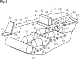
Fig. 5 is a partial perspective view schematically showing an accommodation space and a cooling fan. - An industrial vehicle according to one embodiment will now be described with reference to
Figs. 1 to 5 . In this embodiment, the industrial vehicle is a forklift. In the following, the direction in which an operator of the forklift faces in the forward direction (advancing direction) of the vehicle is defined as a forward direction. The backward, leftward, rightward, upward, and downward directions are defined with reference to the forward direction. - As shown in
Figs. 1 and 2 , aforklift 10, serving as an industrial vehicle, includes avehicle body 11,drive wheels 12, steeredwheels 13, and a material-handling device 14. Theforklift 10 further includestraction motors 30 that drive thedrive wheels 12, apower transmission device 31, material-handling motors 32 that drive the material-handling device 14, and amotor controller 33 that controls thetraction motors 30 and the material-handling motors 32. Theforklift 10 includes abattery 40 serving as a power source for thetraction motors 30 and the material-handling motors 32. - The
vehicle body 11 includes a vehiclemain body 21 and acabin 28, which serves as a driver's compartment arranged on the vehiclemain body 21. A front-rear direction is the front-rear direction of thevehicle body 11, and a left-right direction is the vehicle width direction of thevehicle body 11. - As shown in
Figs. 2 and3 , the vehiclemain body 21 includes afirst bottom portion 22a, asecond bottom portion 22b, twoside portions 23, afront partition plate 24, and acounterweight 25. The twoside portions 23 are spaced apart from each other in the left-right direction. The twoside portions 23 are arranged frontward from thecounterweight 25. Thefirst bottom portion 22a and thesecond bottom portion 22b each extend between the lower portions of the twoside portions 23. Thefront partition plate 24 extends between the front portions of the twoside portions 23. Thefront partition plate 24 forms part of the front end of the vehiclemain body 21. Thefront partition plate 24 is arranged in front of and above thefirst bottom portion 22a. - The
first bottom portion 22a and thesecond bottom portion 22b are spaced apart from each other in the front-rear direction. Thefirst bottom portion 22a is spaced rearward from the front end of the vehiclemain body 21. Thesecond bottom portion 22b is spaced rearward from the rear end of thefirst bottom portion 22a. Thesecond bottom portion 22b is located at a position spaced frontward from the front end of thecounterweight 25. Thefirst bottom portion 22a is arranged downward from thesecond bottom portion 22b. Thus, thesecond bottom portion 22b is arranged upward from thefirst bottom portion 22a. - As shown in
Fig. 4 , thepower transmission device 31 is arranged below thefront partition plate 24. In the vertical direction, a gap S is formed between thefront partition plate 24 and thepower transmission device 31. - As shown in
Figs. 2 ,3 , and5 , thetraction motors 30 are fixed to the upper surface of thefirst bottom portion 22a. Twotraction motors 30 are fixed to thefirst bottom portion 22a. However, the quantity of thetraction motors 30 may be changed. The twotraction motors 30 are arranged in the left-right direction. The material-handling motors 32 are fixed to the upper surface of thesecond bottom portion 22b. Two material-handling motors 32 are fixed to thesecond bottom portion 22b. However, the quantity of the material-handling motors 32 may be changed. The two material-handlingmotors 32 are arranged in the left-right direction. - The
motor controller 33 includes acontrol unit 34 that controls driving of thetraction motors 30 and the material-handlingmotors 32, and afan 35 that cools thecontrol unit 34. Thecontrol unit 34 is arranged upward from thefan 35. Thefan 35 includes a frame-shapedcase 36 andblade members 37 accommodated in thecase 36. Thecase 36 is open in the vertical direction. In other words, thecase 36 is open to thecontrol unit 34 and downward. Thefan 35 sends air downward from thecase 36 as theblade members 37 rotate. Further, thefan 35 discharges heat, generated in thecontrol unit 34, downward as theblade members 37 rotate. - The
motor controller 33 is fixed to the upper portion of the vehiclemain body 21 by a bracket (not shown). Themotor controller 33 is arranged upward from the material-handlingmotors 32. Thefan 35 is spaced upward from the material-handlingmotors 32. - The
first bottom portion 22a, thesecond bottom portion 22b, the twoside portions 23, thefront partition plate 24, and thecounterweight 25 define anaccommodation space 27 inside the vehiclemain body 21. Theaccommodation space 27 extends in the front-rear direction of thevehicle body 11. Thus, thetraction motors 30 fixed to the upper surface of thefirst bottom portion 22a and the material-handlingmotors 32 fixed to the upper surface of thesecond bottom portion 22b are accommodated in theaccommodation space 27. Thefan 35 of themotor controller 33 faces theaccommodation space 27. - The
accommodation space 27 is connected to the outside of thevehicle body 11 through the gap S defined at the front end of the vehiclemain body 21. Thus, theaccommodation space 27 is open at the front end of the vehiclemain body 21. When theforklift 10 travels, a wind is drawn into theaccommodation space 27 inside the vehiclemain body 21 through the gap S. In other words, the wind is drawn into the inside from the front of the vehiclemain body 21. - The wind, drawn into the
accommodation space 27, flows through theaccommodation space 27 to come into contact with thetraction motors 30 and the material-handlingmotors 32. Thus, heat generated in thetraction motors 30 and the material-handlingmotors 32 is discharged to the wind, and thetraction motors 30 and the material-handlingmotors 32 are cooled. In addition, thefan 35 discharges heat, generated in thecontrol unit 34, toward the wind flowing through theaccommodation space 27. Thus, thecontrol unit 34 of themotor controller 33 is cooled. - As shown in
Fig. 1 , the material-handlingdevice 14 is arranged in the front portion of the vehiclemain body 21. The material-handlingdevice 14 includes amast 15 extending upright in the front portion of the vehiclemain body 21, twoforks 16 arranged to be raised or lowered together with themast 15, and alift cylinder 17 that raises or lowers themast 15. A material is placed on theforks 16. Thelift cylinder 17 is a hydraulic cylinder. When thelift cylinder 17 extends or contracts to raise or lower themast 15, theforks 16 are raised or lowered accordingly. The material-handlingdevice 14 is driven by the material-handlingmotors 32. - As shown in
Figs. 2 ,3 , and5 , thecounterweight 25 is a weight for counterbalancing when the material-handlingdevice 14 is loaded with material. Thecounterweight 25 is arranged upward from the steeredwheels 13. Thecounterweight 25 includes aweight body 251 and aweight cover 252. - The
weight body 251 defines aduct forming portion 26 extending in the front-rear direction. Theduct forming portion 26 is recessed from the upper surface of theweight body 251. Theduct forming portion 26 is defined between the opposite sides of theweight body 251 in the left-right direction. Theduct forming portion 26 extends in the front-rear direction of theweight body 251, and has a width in the left-right direction. Theduct forming portion 26 is open at the rear end surface of the vehiclemain body 21. Theduct forming portion 26 is connected to the rear end of theaccommodation space 27. Thus, a wind flowing through theaccommodation space 27 flows into theduct forming portion 26. Theduct forming portion 26 is connected to the outside of thevehicle body 11 through theaccommodation space 27. - The
forklift 10 may include aheat transfer member 39. Theheat transfer member 39 is arranged on the upper surface of theweight body 251. Theheat transfer member 39 is in contact with the upper surface of theweight body 251. Theheat transfer member 39 is formed by a metal plate. - The
battery 40 is placed on the upper surface of theheat transfer member 39. As described above, thecounterweight 25 is arranged in the rear portion of the vehiclemain body 21. Thebattery 40 arranged above the upper surface of thecounterweight 25 is arranged in the rear portion of the vehiclemain body 21. - The
battery 40 is in contact with theheat transfer member 39. Theheat transfer member 39 transfers heat generated in thebattery 40 to theweight body 251. Thus, theheat transfer member 39 is preferably made of metal having a high thermal conductivity. Theweight cover 252 covers thebattery 40 from above. - The
duct forming portion 26 is covered from above by theheat transfer member 39. Theduct forming portion 26 of theweight body 251 and theheat transfer member 39 define aduct 38. Thus, theduct 38 is a space closed in the vertical direction and the left-right direction. However, in the structures of thecounterweight 25, the vehiclemain body 21, and theheat transfer member 39, theduct 38 has a slight gap connected to the outside. Theduct 38 is connected to theaccommodation space 27 and is open to the outside of thevehicle body 11 at the rear end surface of thevehicle body 11. Thus, a wind, drawn into theaccommodation space 27, flows through theduct 38 and is discharged out of thevehicle body 11. - As shown in
Figs. 1 and 2 , thecabin 28 includes atop plate 28a, twoside frames 28b, abottom plate 28c, and aseat base 28d. Thecabin 28 extends upward from the upper surface of the vehiclemain body 21. Although only one of the side frames 28b is shown, the twoside frames 28b are arranged at the opposite sides of the vehiclemain body 21 in the left-right direction. Thebottom plate 28c is arranged on the upper surface of the vehiclemain body 21. Theaccommodation space 27 is covered from above by abottom plate 28c of thecabin 28. Theseat base 28d is arranged on the upper surface of thebottom plate 28c. Theseat base 28d covers themotor controller 33 from above and from the side. Adriver seat 29 is fixed to the upper surface of theseat base 28d. - Thus, the
traction motors 30 and the material-handlingmotors 32 accommodated in theaccommodation space 27 are arranged inside the vehiclemain body 21, below thecabin 28. Themotor controller 33 is arranged inside the vehiclemain body 21, below thecabin 28, and is arranged frontward from thebattery 40. Thebattery 40 is arranged rearward from thecabin 28 in the rear portion of the vehiclemain body 21. - The
forklift 10 includes a coolingfan 50. Theforklift 10 may include anintake regulating plate 53 and aguide regulating plate 54. Theforklift 10 may also include a firstlower cover 61, a secondlower cover 62, and a thirdlower cover 63. - As shown in
Figs. 2 ,3 , and5 , the coolingfan 50 is arranged in theduct 38. Theduct 38 is formed by theduct forming portion 26 of thecounterweight 25. As described above, thecounterweight 25 is arranged in the rear portion of the vehiclemain body 21. Thus, the coolingfan 50 arranged in theduct 38 is located in the rear portion of the vehiclemain body 21 and inside the vehiclemain body 21. Thus, theforklift 10 includes the coolingfan 50 arranged inside the vehiclemain body 21. - The
duct 38 is arranged rearward from theaccommodation space 27. The coolingfan 50 is arranged in theduct 38. Thus, theaccommodation space 27 extends inside the vehiclemain body 21 from the front end of the vehiclemain body 21 to the coolingfan 50. Thus, theaccommodation space 27 extending from the front end of the vehiclemain body 21 to the coolingfan 50 is defined inside the vehiclemain body 21. - The cooling
fan 50 is arranged near the front end of theduct 38. The coolingfan 50 is arranged rearward from the material-handlingmotors 32. Thetraction motors 30 are arranged frontward from the material-handlingmotors 32. Thus, thetraction motors 30 and the material-handlingmotors 32 are arranged frontward from the coolingfan 50. - The cooling
fan 50 is located in the flow of a wind flowing from the front to the rear of the vehiclemain body 21. A direction in which the wind flows from the front to the rear of the vehiclemain body 21 is referred to as a flow direction F. The coolingfan 50 is arranged downstream from thetraction motors 30 and the material-handlingmotors 32 in the flow direction F. The coolingfan 50 is arranged downstream from themotor controller 33. - The cooling
fan 50 includes a frame-shapedcase 51 andblade members 52 accommodated in thecase 51. Thecase 51 is open in the front-rear direction. In other words, thecase 51 is open to theaccommodation space 27 and to theduct 38. The coolingfan 50 discharges air rearward from thecase 51 as theblade members 52 rotate. The coolingfan 50 discharges a wind, flowing from the front to the rear of the vehiclemain body 21, rearward from the material-handlingmotors 32 and thetraction motors 30 as theblade members 52 rotate. The coolingfan 50 draws in air from theaccommodation space 27 and discharges the air to theduct 38. - The
intake regulating plate 53 is arranged at the front end of the vehiclemain body 21. Theintake regulating plate 53 projects from the lower end of thefront partition plate 24 to the front of the vehiclemain body 21. When the vehiclemain body 21 is viewed from one side in the left-right direction, theintake regulating plate 53 extends substantially horizontally frontward from thefront partition plate 24. Theintake regulating plate 53 allows a wind to be drawn into the vehiclemain body 21. - As shown in
Fig. 4 , theintake regulating plate 53 extends in the left-right direction of thefront partition plate 24. Theintake regulating plate 53 is arranged upward from thepower transmission device 31 and upward from the gap S. - As shown in
Figs. 2 ,3 , and5 , twoguide regulating plates 54 are arranged on the vehiclemain body 21. Oneguide regulating plate 54 is arranged on oneside portion 23, and the otherguide regulating plate 54 is arranged on theother side portion 23. Theguide regulating plates 54 are each arranged in the front portions of theside portions 23 and rearward from thefront partition plate 24. Further, theguide regulating plates 54 are each arranged in the upper portion of theside portions 23. The twoguide regulating plates 54 are opposed to each other in the left-right direction. Theguide regulating plates 54 are each arranged upward from thetraction motors 30. - The two
guide regulating plates 54 are accommodated in theaccommodation space 27. Thus, theguide regulating plates 54 are arranged inside the vehiclemain body 21, below thecabin 28. When the vehiclemain body 21 is viewed from one side in the left-right direction, theguide regulating plates 54 each extend downward in an inclined manner from the front end to the rear end. Inside the vehiclemain body 21, theguide regulating plates 54 direct a wind to thetraction motors 30 to cool thetraction motors 30, and guide the wind toward the coolingfan 50. In other words, theguide regulating plates 54 restrict upward diffusion of the wind drawn into the vehiclemain body 21. - The first
lower cover 61 is arranged in the front portion of the vehiclemain body 21. The firstlower cover 61 is rectangular. The firstlower cover 61 extends in the front-rear direction. The width of the firstlower cover 61 extends in the left-right direction. - The first
lower cover 61 covers an area between the front end of the vehiclemain body 21 and thefirst bottom portion 22a from below. Thus, the firstlower cover 61 defines theaccommodation space 27 from below. The firstlower cover 61 is arranged below thepower transmission device 31 and thetraction motors 30. The firstlower cover 61 may be arranged in any manner as long as the firstlower cover 61 is arranged below thetraction motors 30 and covers the area between the front end of the vehiclemain body 21 and thefirst bottom portion 22a from below. - The second
lower cover 62 is arranged between thefirst bottom portion 22a and thesecond bottom portion 22b. The secondlower cover 62 extends between thefirst bottom portion 22a and thesecond bottom portion 22b. The secondlower cover 62 covers an area between thefirst bottom portion 22a and thesecond bottom portion 22b. The secondlower cover 62 is joined to thefirst bottom portion 22a and thesecond bottom portion 22b. Thus, the secondlower cover 62 defines theaccommodation space 27 from below. The secondlower cover 62 may be joined in any manner at any position as long as the secondlower cover 62 extends between thefirst bottom portion 22a and thesecond bottom portion 22b and covers the area between thefirst bottom portion 22a and thesecond bottom portion 22b. - The second
lower cover 62 is inclined upward from thefirst bottom portion 22a to thesecond bottom portion 22b. In other words, the secondlower cover 62 is inclined upward from thetraction motors 30 toward the material-handlingmotors 32. Thesecond bottom portion 22b is arranged frontward from the coolingfan 50. Thus, the secondlower cover 62 is inclined upward toward the coolingfan 50 as the secondlower cover 62 extends from the front end to the rear end. The secondlower cover 62 is located between the front end of the vehiclemain body 21 and the coolingfan 50. Thus, the secondlower cover 62 is an inclined portion located between the front end of the vehiclemain body 21 and the coolingfan 50. - The third
lower cover 63 is arranged between thesecond bottom portion 22b and thecounterweight 25. The thirdlower cover 63 extends between thesecond bottom portion 22b and thecounterweight 25. The thirdlower cover 63 covers an area between thesecond bottom portion 22b and thecounterweight 25. The thirdlower cover 63 is joined to thesecond bottom portion 22b and thecounterweight 25. Thus, the thirdlower cover 63 defines theaccommodation space 27 from below. The thirdlower cover 63 may be joined in any manner at any position as long as the thirdlower cover 63 covers the area between thesecond bottom portion 22b and thecounterweight 25. - The first
lower cover 61, the secondlower cover 62, and the thirdlower cover 63 each define theaccommodation space 27 together with thefirst bottom portion 22a and thesecond bottom portion 22b. In other words, the firstlower cover 61, the secondlower cover 62, and the thirdlower cover 63 each fill portions of theaccommodation space 27 that are open downward. In other words, theforklift 10 includes the first to third lower covers 61 to 63 that cover theaccommodation space 27 from below. - Thus, the
accommodation space 27 is closed from above by thebottom plate 28c of thecabin 28 and is closed from below by the first to third lower covers 61 to 63. Although there is a slight gap in the structure of theforklift 10, theaccommodation space 27 is a closed space. - When the
forklift 10 travels, the coolingfan 50 is driven in conjunction with thetraction motors 30. The coolingfan 50 draws in air from theaccommodation space 27 and discharges the air to theduct 38. - When the
forklift 10 travels, a wind is drawn into the inside from the front of the vehiclemain body 21 through the gap S and the like. In this case, theintake regulating plate 53 allows the wind to easily flow toward the gap S. - Inside the vehicle
main body 21, theguide regulating plates 54 direct part of a wind, flowing into the vehiclemain body 21, to thetraction motors 30 to cool thetraction motors 30 and guide the wind toward the coolingfan 50. Inside thevehicle body 11, the coolingfan 50 draws in air from theaccommodation space 27 and discharges the air to theduct 38. Thus, the coolingfan 50 increases the speed of the wind flowing into theaccommodation space 27. The wind having an increased speed comes into contact with thetraction motors 30, the material-handlingmotors 32, and themotor controller 33. Then the wind passes through the coolingfan 50 and is discharged to theduct 38. - The first
lower cover 61 guides the wind, flowing into theaccommodation space 27, to flow toward thetraction motors 30 without downward diffusion. The secondlower cover 62 guides the wind to flow toward the material-handlingmotors 32 without downward diffusion. The thirdlower cover 63 guides the wind to flow toward the coolingfan 50 without downward diffusion. Heat generated in thecontrol unit 34 of themotor controller 33 is discharged toward theaccommodation space 27 by thefan 35. - The above-described embodiment has the following advantages.
- (1) The
battery 40 is arranged in the rear portion of the vehiclemain body 21. Thetraction motors 30 and the material-handlingmotors 32 are arranged in theaccommodation space 27, frontward from thebattery 40, rearward from the front end of the vehiclemain body 21, and frontward from the coolingfan 50. In such aforklift 10, the wind, drawn into the vehiclemain body 21, flows toward thetraction motors 30 and the material-handlingmotors 32 without being blocked by thebattery 40. The coolingfan 50 discharges the wind, flowing from the front to the rear, rearward from thetraction motors 30 and the material-handlingmotors 32. Thus, the wind, flowing inside the vehiclemain body 21, is drawn into the coolingfan 50 without changing direction. This increases the speed of the wind as compared to when there is no coolingfan 50 or the flow direction of the wind is changed. When wind having an increased speed comes into contact with thetraction motors 30, the material-handlingmotors 32, and themotor controller 33, the cooling efficiency of such heating elements is improved. - (2) The
intake regulating plate 53 guides the wind toward the gap S. Thus, the amount of the wind drawn into the vehiclemain body 21 is increased as compared to when there is nointake regulating plate 53. This improves the cooling efficiency of thetraction motors 30, the material-handlingmotors 32, and themotor controller 33 using the wind as compared to when there is nointake regulating plate 53. - (3) The
guide regulating plates 54 restrict upward diffusion of the wind drawn into the vehiclemain body 21. Thus, inside the vehiclemain body 21, theguide regulating plates 54 direct the wind to thetraction motors 30 to cool thetraction motors 30 and guide the wind toward the coolingfan 50. This improves the cooling efficiency of thetraction motors 30, the material-handlingmotors 32, and themotor controller 33 using the wind as compared to when there is noguide regulating plates 54. - (4) The
forklift 10 includes theintake regulating plate 53 and theguide regulating plates 54. Thus, theintake regulating plate 53 and theguide regulating plates 54 further improve the cooling efficiency of thetraction motors 30, the material-handlingmotors 32, and themotor controller 33. - (5) The
accommodation space 27 accommodates thetraction motors 30 and the material-handlingmotors 32. The lower side of theaccommodation space 27 is covered by the firstlower cover 61, the secondlower cover 62, and the thirdlower cover 63. The first to third lower covers 61 to 63 restrict downward diffusion of the wind flowing through theaccommodation space 27. This avoids a decrease in the airflow rate of the wind due to the diffusion. This also avoids a decrease in the cooling efficiency of thetraction motors 30, the material-handlingmotors 32, and themotor controller 33 using the wind. - (6) The first
lower cover 61 extends from the front end of the vehiclemain body 21 to the lower side of thetraction motors 30. The firstlower cover 61 guides the wind, drawn in from the front end of the vehiclemain body 21, to thetraction motors 30 while restricting downward diffusion of the wind. Thus, the firstlower cover 61 improves the cooling efficiency of thetraction motors 30. - (7) The material-handling
motors 32 are arranged upward from thetraction motors 30. The secondlower cover 62 is inclined upward from thetraction motors 30 toward the material-handlingmotors 32. The secondlower cover 62 guides the wind to the material-handlingmotors 32 while restricting downward diffusion of the wind. Thus, the secondlower cover 62 improves the cooling efficiency of the material-handlingmotors 32. - (8) The third
lower cover 63 extends from the rear ends of the material-handlingmotors 32 to the coolingfan 50. The thirdlower cover 63 guides the wind toward the coolingfan 50 while restricting downward diffusion of the wind. Thus, the thirdlower cover 63 improves the air-blowing efficiency of the coolingfan 50. - (9) The cooling
fan 50 is arranged downstream from the material-handlingmotors 32 in the flow direction F. The coolingfan 50 draws in the wind along the flow direction F. Thus, the coolingfan 50, drawing in the wind without pressure loss, increases the speed of the wind in a preferred manner. - (10) The
motor controller 33 is arranged such that thefan 35 is directed to theaccommodation space 27. Heat generated in thecontrol unit 34 is discharged to theaccommodation space 27 by thefan 35. Then, the heat, discharged to theaccommodation space 27, is discharged out of thevehicle body 11 along with the wind. This improves the cooling efficiency of thecontrol unit 34 as compared to when thefan 35 does not face theaccommodation space 27. - (11) The
traction motors 30 and the material-handlingmotors 32 are arranged between the coolingfan 50 and the front end of the vehiclemain body 21 in the front-rear direction. The wind having an increased speed comes into contact with thetraction motors 30 and the material-handlingmotors 32. Thus, the coolingfan 50 improves the cooling efficiency of thetraction motors 30 and the material-handlingmotors 32. - (12) The
forklift 10 includes theduct 38 inside thecounterweight 25. Theduct 38 allows air, drawn in by the coolingfan 50, to be discharged out of thevehicle body 11. Thus, theduct 38 avoids heat accumulation inside thevehicle body 11. - (13) The
heat transfer member 39 transfers the heat of thebattery 40 to thecounterweight 25. Thus, theheat transfer member 39 restricts an excessive rise in the temperature of thebattery 40. - (14) The
heat transfer member 39 covers theduct forming portion 26 of thecounterweight 25 from above. Theduct 38 is defined by theduct forming portion 26 and theheat transfer member 39. The wind flowing through theduct 38 comes into contact with theheat transfer member 39. Thus, since theheat transfer member 39 is cooled with the wind, thebattery 40 is cooled with the wind. - (15) The
motor controller 33 is arranged upward from theaccommodation space 27. Thus, themotor controller 33 does not impede the flow of the wind in theaccommodation space 27. Thefan 35 of themotor controller 33 faces theaccommodation space 27. Thefan 35 discharges the heat of thecontrol unit 34 to theaccommodation space 27. Thus, themotor controller 33 arranged at the suitable position allows for the cooling of themotor controller 33 in a preferred manner while improving the cooling efficiency of thetraction motors 30 and the material-handlingmotors 32 using the wind. - (16) A mere addition of the cooling
fan 50 improves the cooling efficiency of thetraction motors 30, the material-handlingmotors 32, and themotor controller 33 using the wind. For example, unlike a case in which thetraction motors 30, the material-handlingmotors 32, and themotor controller 33 are water-cooled, theforklift 10 does not need large-scale equipment such as a refrigerant pipe, a radiator fan, and a radiator. Thus, as compared to water cooling, the arrangement of the coolingfan 50 improves the cooling efficiency of thetraction motors 30, the material-handlingmotors 32, and themotor controller 33 at lower cost. - The present embodiment may be modified as described below. The present embodiment and the following modifications can be combined if the combined modifications remain technically consistent with each other.
- The
fan 35 of themotor controller 33 does not need to face theaccommodation space 27. - The
motor controller 33 may include only thecontrol unit 34 without thefan 35. In this case, thecontrol unit 34 of themotor controller 33 preferably faces theaccommodation space 27. With this structure, heat generated in thecontrol unit 34 is discharged to a wind flowing in theaccommodation space 27. - The positions of the
first bottom portion 22a and thesecond bottom portion 22b in the vertical direction may be changed. The inclination of the secondlower cover 62 may be changed in accordance with the positions of thefirst bottom portion 22a and thesecond bottom portion 22b in the vertical direction. When thefirst bottom portion 22a and thesecond bottom portion 22b are at the same position in the vertical direction, the secondlower cover 62 extends horizontally between thefirst bottom portion 22a and thesecond bottom portion 22b. In contrast, when thefirst bottom portion 22a is arranged upward from thesecond bottom portion 22b, the secondlower cover 62 is inclined downward from thefirst bottom portion 22a to thesecond bottom portion 22b. - When the
second bottom portion 22b is located downward from theduct forming portion 26, the thirdlower cover 63 is arranged to be inclined upward from thesecond bottom portion 22b to thecounterweight 25. In other words, the thirdlower cover 63 is inclined upward toward the coolingfan 50 as the thirdlower cover 63 extends from the front end to the rear end. In this case, the thirdlower cover 63 is an inclined portion located between the front end of the vehiclemain body 21 and the coolingfan 50. - At least one of the first to third lower covers 61 to 63 may be omitted.
- The lower side of the
accommodation space 27 may be covered by a single lower cover from the front end of the vehiclemain body 21 to the front end of thecounterweight 25. - The
forklift 10 only needs to include at least one of theintake regulating plate 53 and theguide regulating plates 54. The expression "at least one of theintake regulating plate 53 and theguide regulating plates 54" used in the present specification means only theintake regulating plate 53, only theguide regulating plates 54, or both theintake regulating plate 53 and theguide regulating plates 54. - The
motor controller 33 may be arranged inside theaccommodation space 27. For example, themotor controller 33 may be arranged between thetraction motors 30 and the material-handlingmotors 32 in the front-rear direction. Alternatively, themotor controller 33 may be arranged between the material-handlingmotors 32 and the coolingfan 50 in the front-rear direction. - The positions of the
traction motors 30 and the material-handlingmotors 32 in the front-rear direction may be swapped. - The industrial vehicle may be any type of vehicle other than the
forklift 10.
Claims (5)
- An industrial vehicle, comprising:a vehicle main body into which a wind is drawn from a front;a cabin arranged on the vehicle main body;a material-handling device arranged in a front portion of the vehicle main body;a material-handling motor arranged inside the vehicle main body, below the cabin;a traction motor arranged inside the vehicle main body, below the cabin;a motor controller arranged inside the vehicle main body, below the cabin, the motor controller controlling the material-handling motor and the traction motor;a battery serving as a power source for the material-handling motor and the traction motor; anda cooling fan arranged inside the vehicle main body, whereinthe battery is arranged rearward from the cabin in a rear portion of the vehicle main body,the motor controller is arranged frontward from the battery,the material-handling motor and the traction motor are arranged frontward from the cooling fan, andthe cooling fan discharges the wind, flowing from the front to a rear of the vehicle main body, to a rear of the material-handling motor and the traction motor.
- The industrial vehicle according to claim 1, further comprising at least one of an intake regulating plate and a guide regulating plate, whereinthe intake regulating plate projects frontward from a front end of the vehicle main body and allows the wind to be drawn into the vehicle main body, andthe guide regulating plate is arranged inside the vehicle main body, below the cabin, and guides the wind toward the cooling fan.
- The industrial vehicle according to claim 1 or 2, further comprising a lower cover, whereinan accommodation space extending from a front end of the vehicle main body to the cooling fan is defined inside the vehicle main body,the traction motor and the material-handling motor are accommodated in the accommodation space, andthe lower cover covers the accommodation space from below.
- The industrial vehicle according to claim 3, whereinthe lower cover includes an inclined portion located between the front end of the vehicle main body and the cooling fan, andthe inclined portion is inclined upward toward the cooling fan as the inclined portion extends from a front to a rear.
- The industrial vehicle according to claim 3 or 4, whereinthe motor controller includes:a control unit that controls the material-handling motor and the traction motor; anda fan that cools the control unit, andthe fan faces the accommodation space.
Applications Claiming Priority (2)
| Application Number | Priority Date | Filing Date | Title |
|---|---|---|---|
| JP2022057417A JP7786284B2 (en) | 2022-03-30 | 2022-03-30 | Industrial vehicles |
| PCT/JP2023/010960 WO2023189841A1 (en) | 2022-03-30 | 2023-03-20 | Industrial vehicle |
Publications (2)
| Publication Number | Publication Date |
|---|---|
| EP4501677A1 true EP4501677A1 (en) | 2025-02-05 |
| EP4501677A4 EP4501677A4 (en) | 2025-08-06 |
Family
ID=88201178
Family Applications (1)
| Application Number | Title | Priority Date | Filing Date |
|---|---|---|---|
| EP23779857.4A Pending EP4501677A4 (en) | 2022-03-30 | 2023-03-20 | INDUSTRIAL TRUCK |
Country Status (8)
| Country | Link |
|---|---|
| US (1) | US20250206587A1 (en) |
| EP (1) | EP4501677A4 (en) |
| JP (1) | JP7786284B2 (en) |
| CN (1) | CN118973841A (en) |
| AU (1) | AU2023244261B2 (en) |
| CA (1) | CA3246528A1 (en) |
| TW (1) | TWI863191B (en) |
| WO (1) | WO2023189841A1 (en) |
Family Cites Families (6)
| Publication number | Priority date | Publication date | Assignee | Title |
|---|---|---|---|---|
| JPS62125648U (en) * | 1986-02-01 | 1987-08-10 | ||
| JP2592250Y2 (en) * | 1993-05-14 | 1999-03-17 | 小松フォークリフト株式会社 | Engine cooling device |
| JPH0932550A (en) * | 1995-07-14 | 1997-02-04 | Toyota Autom Loom Works Ltd | Engine cooling system of industrial vehicle |
| JP2004122916A (en) | 2002-10-02 | 2004-04-22 | Mitsubishi Heavy Ind Ltd | Cooling device for electric working vehicle |
| DE112013000002T5 (en) * | 2013-01-08 | 2014-11-06 | Komatsu Ltd. | Battery powered forklift |
| JP7200852B2 (en) * | 2019-06-28 | 2023-01-10 | トヨタ自動車株式会社 | electric vehicle |
-
2022
- 2022-03-30 JP JP2022057417A patent/JP7786284B2/en active Active
-
2023
- 2023-03-20 CA CA3246528A patent/CA3246528A1/en active Pending
- 2023-03-20 CN CN202380030245.6A patent/CN118973841A/en active Pending
- 2023-03-20 WO PCT/JP2023/010960 patent/WO2023189841A1/en not_active Ceased
- 2023-03-20 US US18/850,411 patent/US20250206587A1/en active Pending
- 2023-03-20 AU AU2023244261A patent/AU2023244261B2/en active Active
- 2023-03-20 EP EP23779857.4A patent/EP4501677A4/en active Pending
- 2023-03-24 TW TW112111141A patent/TWI863191B/en active
Also Published As
| Publication number | Publication date |
|---|---|
| CA3246528A1 (en) | 2025-01-23 |
| TW202408918A (en) | 2024-03-01 |
| US20250206587A1 (en) | 2025-06-26 |
| TWI863191B (en) | 2024-11-21 |
| AU2023244261B2 (en) | 2025-12-18 |
| AU2023244261A1 (en) | 2024-10-03 |
| EP4501677A4 (en) | 2025-08-06 |
| JP2023149063A (en) | 2023-10-13 |
| JP7786284B2 (en) | 2025-12-16 |
| WO2023189841A1 (en) | 2023-10-05 |
| CN118973841A (en) | 2024-11-15 |
Similar Documents
| Publication | Publication Date | Title |
|---|---|---|
| JP5684768B2 (en) | Work vehicle | |
| JP7238812B2 (en) | Vehicle cooling structure | |
| US8297387B2 (en) | Electric vehicle | |
| JP6308009B2 (en) | Battery pack | |
| JP3713480B2 (en) | Electric drive wheeled work vehicle | |
| US20230272594A1 (en) | Work Machine | |
| CN104039598B (en) | Battery-type working machines and battery-type forklifts | |
| US20120055725A1 (en) | Vehicle battery cooling structure | |
| CN112109590B (en) | Cooling mechanism for vehicles | |
| CN104041203B (en) | Battery-type Work machine and battery-type fork truck | |
| CN109017343B (en) | Fuel cell vehicle and control method thereof | |
| JPWO2014109000A1 (en) | Battery powered forklift | |
| JP2017114153A (en) | Service car | |
| EP4501677A1 (en) | Industrial vehicle | |
| US20140339001A1 (en) | Cab, and work vehicle | |
| JP2010052894A (en) | Industrial vehicle | |
| JP2018206749A (en) | Fuel cell vehicle | |
| JP6207795B1 (en) | Heater device and work vehicle | |
| KR20240060840A (en) | electric shovel | |
| US20250042219A1 (en) | Work machine | |
| JP4484201B2 (en) | Counterbalance forklift | |
| JP6688825B2 (en) | vehicle | |
| CN218243187U (en) | Driving and controlling integrated motor | |
| CN121909125A (en) | Electric dump truck | |
| JP2024156396A (en) | Battery-powered industrial vehicles |
Legal Events
| Date | Code | Title | Description |
|---|---|---|---|
| STAA | Information on the status of an ep patent application or granted ep patent |
Free format text: STATUS: THE INTERNATIONAL PUBLICATION HAS BEEN MADE |
|
| PUAI | Public reference made under article 153(3) epc to a published international application that has entered the european phase |
Free format text: ORIGINAL CODE: 0009012 |
|
| STAA | Information on the status of an ep patent application or granted ep patent |
Free format text: STATUS: REQUEST FOR EXAMINATION WAS MADE |
|
| 17P | Request for examination filed |
Effective date: 20240919 |
|
| AK | Designated contracting states |
Kind code of ref document: A1 Designated state(s): AL AT BE BG CH CY CZ DE DK EE ES FI FR GB GR HR HU IE IS IT LI LT LU LV MC ME MK MT NL NO PL PT RO RS SE SI SK SM TR |
|
| DAV | Request for validation of the european patent (deleted) | ||
| DAX | Request for extension of the european patent (deleted) | ||
| A4 | Supplementary search report drawn up and despatched |
Effective date: 20250709 |
|
| RIC1 | Information provided on ipc code assigned before grant |
Ipc: B60K 11/06 20060101AFI20250703BHEP Ipc: B60K 1/02 20060101ALI20250703BHEP Ipc: B60K 1/04 20190101ALI20250703BHEP Ipc: B66F 9/075 20060101ALI20250703BHEP Ipc: B60K 1/00 20060101ALI20250703BHEP |