EP4501593A1 - Verpackungsmaschine - Google Patents
Verpackungsmaschine Download PDFInfo
- Publication number
- EP4501593A1 EP4501593A1 EP23382803.7A EP23382803A EP4501593A1 EP 4501593 A1 EP4501593 A1 EP 4501593A1 EP 23382803 A EP23382803 A EP 23382803A EP 4501593 A1 EP4501593 A1 EP 4501593A1
- Authority
- EP
- European Patent Office
- Prior art keywords
- actuation
- motor assembly
- assembly
- packaging machine
- reference support
- Prior art date
- Legal status (The legal status is an assumption and is not a legal conclusion. Google has not performed a legal analysis and makes no representation as to the accuracy of the status listed.)
- Granted
Links
Images


Classifications
-
- B—PERFORMING OPERATIONS; TRANSPORTING
- B29—WORKING OF PLASTICS; WORKING OF SUBSTANCES IN A PLASTIC STATE IN GENERAL
- B29C—SHAPING OR JOINING OF PLASTICS; SHAPING OF MATERIAL IN A PLASTIC STATE, NOT OTHERWISE PROVIDED FOR; AFTER-TREATMENT OF THE SHAPED PRODUCTS, e.g. REPAIRING
- B29C66/00—General aspects of processes or apparatus for joining preformed parts
- B29C66/80—General aspects of machine operations or constructions and parts thereof
- B29C66/84—Specific machine types or machines suitable for specific applications
- B29C66/849—Packaging machines
-
- B—PERFORMING OPERATIONS; TRANSPORTING
- B65—CONVEYING; PACKING; STORING; HANDLING THIN OR FILAMENTARY MATERIAL
- B65B—MACHINES, APPARATUS OR DEVICES FOR, OR METHODS OF, PACKAGING ARTICLES OR MATERIALS; UNPACKING
- B65B65/00—Details peculiar to packaging machines and not otherwise provided for; Arrangements of such details
- B65B65/02—Driving gear
-
- B—PERFORMING OPERATIONS; TRANSPORTING
- B29—WORKING OF PLASTICS; WORKING OF SUBSTANCES IN A PLASTIC STATE IN GENERAL
- B29C—SHAPING OR JOINING OF PLASTICS; SHAPING OF MATERIAL IN A PLASTIC STATE, NOT OTHERWISE PROVIDED FOR; AFTER-TREATMENT OF THE SHAPED PRODUCTS, e.g. REPAIRING
- B29C65/00—Joining or sealing of preformed parts, e.g. welding of plastics materials; Apparatus therefor
- B29C65/02—Joining or sealing of preformed parts, e.g. welding of plastics materials; Apparatus therefor by heating, with or without pressure
-
- B—PERFORMING OPERATIONS; TRANSPORTING
- B29—WORKING OF PLASTICS; WORKING OF SUBSTANCES IN A PLASTIC STATE IN GENERAL
- B29C—SHAPING OR JOINING OF PLASTICS; SHAPING OF MATERIAL IN A PLASTIC STATE, NOT OTHERWISE PROVIDED FOR; AFTER-TREATMENT OF THE SHAPED PRODUCTS, e.g. REPAIRING
- B29C65/00—Joining or sealing of preformed parts, e.g. welding of plastics materials; Apparatus therefor
- B29C65/78—Means for handling the parts to be joined, e.g. for making containers or hollow articles, e.g. means for handling sheets, plates, web-like materials, tubular articles, hollow articles or elements to be joined therewith; Means for discharging the joined articles from the joining apparatus
- B29C65/7858—Means for handling the parts to be joined, e.g. for making containers or hollow articles, e.g. means for handling sheets, plates, web-like materials, tubular articles, hollow articles or elements to be joined therewith; Means for discharging the joined articles from the joining apparatus characterised by the feeding movement of the parts to be joined
- B29C65/7888—Means for handling of moving sheets or webs
- B29C65/7891—Means for handling of moving sheets or webs of discontinuously moving sheets or webs
-
- B—PERFORMING OPERATIONS; TRANSPORTING
- B29—WORKING OF PLASTICS; WORKING OF SUBSTANCES IN A PLASTIC STATE IN GENERAL
- B29C—SHAPING OR JOINING OF PLASTICS; SHAPING OF MATERIAL IN A PLASTIC STATE, NOT OTHERWISE PROVIDED FOR; AFTER-TREATMENT OF THE SHAPED PRODUCTS, e.g. REPAIRING
- B29C65/00—Joining or sealing of preformed parts, e.g. welding of plastics materials; Apparatus therefor
- B29C65/78—Means for handling the parts to be joined, e.g. for making containers or hollow articles, e.g. means for handling sheets, plates, web-like materials, tubular articles, hollow articles or elements to be joined therewith; Means for discharging the joined articles from the joining apparatus
- B29C65/7858—Means for handling the parts to be joined, e.g. for making containers or hollow articles, e.g. means for handling sheets, plates, web-like materials, tubular articles, hollow articles or elements to be joined therewith; Means for discharging the joined articles from the joining apparatus characterised by the feeding movement of the parts to be joined
- B29C65/7888—Means for handling of moving sheets or webs
- B29C65/7894—Means for handling of moving sheets or webs of continuously moving sheets or webs
-
- B—PERFORMING OPERATIONS; TRANSPORTING
- B29—WORKING OF PLASTICS; WORKING OF SUBSTANCES IN A PLASTIC STATE IN GENERAL
- B29C—SHAPING OR JOINING OF PLASTICS; SHAPING OF MATERIAL IN A PLASTIC STATE, NOT OTHERWISE PROVIDED FOR; AFTER-TREATMENT OF THE SHAPED PRODUCTS, e.g. REPAIRING
- B29C66/00—General aspects of processes or apparatus for joining preformed parts
- B29C66/40—General aspects of joining substantially flat articles, e.g. plates, sheets or web-like materials; Making flat seams in tubular or hollow articles; Joining single elements to substantially flat surfaces
- B29C66/41—Joining substantially flat articles ; Making flat seams in tubular or hollow articles
- B29C66/43—Joining a relatively small portion of the surface of said articles
- B29C66/431—Joining the articles to themselves
- B29C66/4312—Joining the articles to themselves for making flat seams in tubular or hollow articles, e.g. transversal seams
-
- B—PERFORMING OPERATIONS; TRANSPORTING
- B29—WORKING OF PLASTICS; WORKING OF SUBSTANCES IN A PLASTIC STATE IN GENERAL
- B29C—SHAPING OR JOINING OF PLASTICS; SHAPING OF MATERIAL IN A PLASTIC STATE, NOT OTHERWISE PROVIDED FOR; AFTER-TREATMENT OF THE SHAPED PRODUCTS, e.g. REPAIRING
- B29C66/00—General aspects of processes or apparatus for joining preformed parts
- B29C66/40—General aspects of joining substantially flat articles, e.g. plates, sheets or web-like materials; Making flat seams in tubular or hollow articles; Joining single elements to substantially flat surfaces
- B29C66/41—Joining substantially flat articles ; Making flat seams in tubular or hollow articles
- B29C66/43—Joining a relatively small portion of the surface of said articles
- B29C66/432—Joining a relatively small portion of the surface of said articles for making tubular articles or closed loops, e.g. by joining several sheets ; for making hollow articles or hollow preforms
- B29C66/4322—Joining a relatively small portion of the surface of said articles for making tubular articles or closed loops, e.g. by joining several sheets ; for making hollow articles or hollow preforms by joining a single sheet to itself
-
- B—PERFORMING OPERATIONS; TRANSPORTING
- B29—WORKING OF PLASTICS; WORKING OF SUBSTANCES IN A PLASTIC STATE IN GENERAL
- B29C—SHAPING OR JOINING OF PLASTICS; SHAPING OF MATERIAL IN A PLASTIC STATE, NOT OTHERWISE PROVIDED FOR; AFTER-TREATMENT OF THE SHAPED PRODUCTS, e.g. REPAIRING
- B29C66/00—General aspects of processes or apparatus for joining preformed parts
- B29C66/80—General aspects of machine operations or constructions and parts thereof
- B29C66/82—Pressure application arrangements, e.g. transmission or actuating mechanisms for joining tools or clamps
- B29C66/822—Transmission mechanisms
- B29C66/8221—Scissor or lever mechanisms, i.e. involving a pivot point
-
- B—PERFORMING OPERATIONS; TRANSPORTING
- B29—WORKING OF PLASTICS; WORKING OF SUBSTANCES IN A PLASTIC STATE IN GENERAL
- B29C—SHAPING OR JOINING OF PLASTICS; SHAPING OF MATERIAL IN A PLASTIC STATE, NOT OTHERWISE PROVIDED FOR; AFTER-TREATMENT OF THE SHAPED PRODUCTS, e.g. REPAIRING
- B29C66/00—General aspects of processes or apparatus for joining preformed parts
- B29C66/80—General aspects of machine operations or constructions and parts thereof
- B29C66/82—Pressure application arrangements, e.g. transmission or actuating mechanisms for joining tools or clamps
- B29C66/822—Transmission mechanisms
- B29C66/8225—Crank mechanisms
-
- B—PERFORMING OPERATIONS; TRANSPORTING
- B29—WORKING OF PLASTICS; WORKING OF SUBSTANCES IN A PLASTIC STATE IN GENERAL
- B29C—SHAPING OR JOINING OF PLASTICS; SHAPING OF MATERIAL IN A PLASTIC STATE, NOT OTHERWISE PROVIDED FOR; AFTER-TREATMENT OF THE SHAPED PRODUCTS, e.g. REPAIRING
- B29C66/00—General aspects of processes or apparatus for joining preformed parts
- B29C66/80—General aspects of machine operations or constructions and parts thereof
- B29C66/83—General aspects of machine operations or constructions and parts thereof characterised by the movement of the joining or pressing tools
- B29C66/832—Reciprocating joining or pressing tools
- B29C66/8322—Joining or pressing tools reciprocating along one axis
- B29C66/83221—Joining or pressing tools reciprocating along one axis cooperating reciprocating tools, each tool reciprocating along one axis
-
- B—PERFORMING OPERATIONS; TRANSPORTING
- B65—CONVEYING; PACKING; STORING; HANDLING THIN OR FILAMENTARY MATERIAL
- B65B—MACHINES, APPARATUS OR DEVICES FOR, OR METHODS OF, PACKAGING ARTICLES OR MATERIALS; UNPACKING
- B65B31/00—Packaging articles or materials under special atmospheric or gaseous conditions; Adding propellants to aerosol containers
-
- B—PERFORMING OPERATIONS; TRANSPORTING
- B65—CONVEYING; PACKING; STORING; HANDLING THIN OR FILAMENTARY MATERIAL
- B65B—MACHINES, APPARATUS OR DEVICES FOR, OR METHODS OF, PACKAGING ARTICLES OR MATERIALS; UNPACKING
- B65B51/00—Devices for, or methods of, sealing or securing package folds or closures; Devices for gathering or twisting wrappers, or necks of bags
- B65B51/10—Applying or generating heat or pressure or combinations thereof
- B65B51/26—Devices specially adapted for producing transverse or longitudinal seams in webs or tubes
- B65B51/30—Devices, e.g. jaws, for applying pressure and heat, e.g. for subdividing filled tubes
- B65B51/303—Devices, e.g. jaws, for applying pressure and heat, e.g. for subdividing filled tubes reciprocating along only one axis
-
- B—PERFORMING OPERATIONS; TRANSPORTING
- B65—CONVEYING; PACKING; STORING; HANDLING THIN OR FILAMENTARY MATERIAL
- B65B—MACHINES, APPARATUS OR DEVICES FOR, OR METHODS OF, PACKAGING ARTICLES OR MATERIALS; UNPACKING
- B65B9/00—Enclosing successive articles, or quantities of material, e.g. liquids or semiliquids, in flat, folded, or tubular webs of flexible sheet material; Subdividing filled flexible tubes to form packages
- B65B9/10—Enclosing successive articles, or quantities of material, in preformed tubular webs, or in webs formed into tubes around filling nozzles, e.g. extruded tubular webs
- B65B9/20—Enclosing successive articles, or quantities of material, in preformed tubular webs, or in webs formed into tubes around filling nozzles, e.g. extruded tubular webs the webs being formed into tubes in situ around the filling nozzles
- B65B9/207—Enclosing successive articles, or quantities of material, in preformed tubular webs, or in webs formed into tubes around filling nozzles, e.g. extruded tubular webs the webs being formed into tubes in situ around the filling nozzles the web advancing continuously
Definitions
- the present invention relates to packaging machines, with which products, preferably foodstuffs, are packaged.
- packaging machines such as vertical packaging machines, horizontal packaging machines, thermo-forming machines, thermo-sealing machines, or packaging machines that create a vacuum in a bag containing a product inside and seal the bags (also known as vacuum chamber machines).
- a plurality of operations are performed during the packaging of a product, and which operations are performed or how the operations to be performed depend on the type of packaging machine.
- shaping a film sealing a station to generate a vacuum
- sealing a lid film to a base film or a tray
- making a longitudinal seal to generate a film tube or making a transversal seal to seal and close transversally such a film tube, for example.
- such a packaging machine may comprise two actuation elements analogous to those described in terms of displacement requirements but configured to perform a different operation.
- two actuation elements are used opposite each other as, for example, product compactors, to ensure that the product is correctly positioned inside the film tube before and/or during transverse sealing of the film tube.
- EP3674222A1 describes various operations of a packaging machine.
- This packaging machine comprises a sealing assembly with a first actuating element and a second actuating element facing each other, and a drive configured to cause simultaneous displacement of the actuating elements.
- the drive comprises a drive support, a motor assembly with a stator attached to the drive support and a rotor with a longitudinal axis.
- the actuating elements are attached to the drive support with freedom to move away from or towards each other by the action of the drive motor assembly and are also attached to the rotor of the drive such that rotation of the rotor of the drive causes simultaneous displacement of both sealing elements relative to the drive support.
- the connection between the actuating elements and the rotor is made in such a way that the rotation of the rotor causes the simultaneous displacement of both actuating elements in different directions.
- the object of the invention is to provide a packaging machine as defined in the claims.
- the packaging machine comprises an actuation assembly that is configured to take part in an operation during product packaging and that is associated with a reference support of the machine.
- the actuation assembly comprises at least one linearly displaceable actuation element and a drive configured to cause linear displacement of the actuation element.
- the drive comprises a motor assembly which is attached to the reference support and which is associated with the actuating element such that when driven, it causes linear displacement of the actuating element.
- the drive comprises a first linkage mechanism linking the actuation element to a rotor of the motor assembly and a second linkage mechanism linking the actuation element to a stator of the motor assembly.
- the motor assembly is attached to the reference support such that, when the motor assembly is driven, the stator and the rotor rotate relative to the reference support in opposite directions of rotation and said rotations cause the linear displacement of the actuation element thanks to the linkage mechanisms.
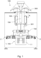
- Figure 1 shows an embodiment of a packaging machine 100, which is adapted for packaging products and which is configured to be able to perform at least one operation for this purpose, and comprises at least one actuation assembly 1 configured to take part in at least one such operation.
- the actuation assembly 1 comprises a linearly displaceable actuation element 1.1 and a drive 2 configured to cause linear displacement of said actuation element 1.1 so that said actuation assembly 1 takes part in the corresponding operation during packaging of products.
- the drive 2 comprises a motor assembly 2.1 (see figures 2 and 3 ) which is associated with the actuation element 1.1 in such a way that when said motor assembly 2.1 is driven it causes the linear displacement of said actuation element 1.1.
- Said actuation assembly 1 is attached to a reference support 101 of the machine 100, in such a way that said motor assembly 2.1 is supported in the machine 100.
- said reference support 101 may be the frame of the machine 100 itself, although it could also be a movable element of the machine 100.
- the actuation element 1.1 is preferably associated with the reference support 101, it being linearly displaceable with respect to said reference support 101 when it displaces (regardless of whether in some embodiments the reference support 101 moves or not).
- the drive 2 comprises a first linkage mechanism 2.41 linking the actuation element 1.1 to a rotor 2.11 of the motor assembly 2.1 (see figure 5 ) and a second linkage mechanism 2.42 linking said actuation element 1.1 to a stator 2.10 of said motor assembly 2.1.
- the motor assembly 2.1 is attached to the reference support 101 in such a way that, when said motor assembly 2.1 is driven, the stator 2.10 and the rotor 2.11 rotate with respect to the reference support 101 in opposite directions of rotation, and it is these rotations which cause the linear displacement of the actuation element 1.1 due to the linkage mechanisms 2.41 and 2.42.
- At least one of the elements of the motor assembly 2.1 between the stator 2.10 and the rotor 2.11 is connected to the reference support 101, this connection being the one which establishes the connection between the motor assembly 2.1 and the reference support 101.
- Said element (stator 2.10 and/or rotor 2.11) is connected to said reference support 101 with freedom of rotation, preferably by means of a bearing 2.7 or 2.8.
- it is the stator 2.10 which is freely rotatably attached to the reference support 101, although it could be both elements (stator 2.10 and rotor 2.11) which are freely rotatably attached to the reference support 101 (see figures 5 and 9 for example), or only the rotor 2.11.
- the actuation element 1.1 is linearly displaceable in a first direction and in a second direction opposite to said first direction, and the two linkage mechanisms 2.41 and 2.42 are configured to exert a simultaneous respective thrust F2.10, F2.11 on said actuation element 1.1 in the same direction, between said first direction and said second direction, when the motor assembly 2.1 is driven, as shown in figures 3 and 4 where a linear displacement of the actuation element 1.1 is represented.
- both rotations, that of the rotor 2.11 and that of the stator 2.10 contribute to the displacement of said actuation element 1.1, without one opposing the other despite being rotations in opposite directions.
- each linkage mechanism 2.41 and 2.42 is a connecting rod-crank mechanism as will be described below.
- a connecting rod-crank mechanism is to be interpreted as a mechanism comprising at least one connecting rod and one crank, or a mechanism comprising at least one eccentric and one connecting rod, in either case transforming a rotational displacement into a linear displacement.
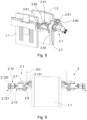
- the machine 100 comprises at least one actuation assembly 1 with a second actuation element 1.2 linearly displaceable and facing the first actuation element 1.1, as depicted in the examples of Figures 6 and 7 .
- said second actuation element 1.2 is attached with freedom of linear displacement to the reference support 101.
- the actuator 2 is configured to cause the two actuating elements 1.1 and 1.2 to displace simultaneously, preferably in opposite directions (so as to move towards or away from each other during such movement).
- the drive 2 comprises a third linkage mechanism 2.43 for linking the second actuation element 1.2 to the motor assembly 2.1 (to the rotor 2.11, as depicted in the figures, or to the stator 2.10), to cause linear displacement of the second actuation element 1.2.
- the third linkage mechanism 2.43 is configured to exert a thrust on the second actuation element 1.2 when actuation of the motor assembly 2.1 is caused, which is in a direction opposite to the direction of the thrusts F2.10 and F2.11 exerted on the first actuation element 1.1 when the actuation elements 1.1 and 1.2 move in opposite directions.
- said actuating elements 1.1 and 1.2 comprise a relative displacement between them to perform the corresponding operation such that the distance between them is reduced (to clamp a sheet between them, for example) or such that said distance is increased (once said operation has been completed).
- actuation assembly 1 with two actuation elements 1.1 and 1.2 is briefly described below with the aid of the figures.
- This example and those previously described (both for actuation assemblies with two actuation elements and for actuation assemblies with only one actuation element), is in no way limiting and the machine can comprise 100 actuation assemblies not described in these examples.
- the machine 100 is adapted to generate the packaging from a film 300 which is fed continuously or intermittently and given a tubular shape.
- a film 300 which is fed continuously or intermittently and given a tubular shape.
- the sheet 300 which surrounds said forming tube 105
- the machine 100 comprises a longitudinal sealing assembly 104, for sealing together longitudinal ends of the tubular shaped foil to form a foil tube 301.
- the machine 100 further comprises a transversely sealing assembly 102 downstream of the longitudinal sealing assembly 104 in a feed direction A of the foil tube 301, for at least transversely sealing the film tube 301 and generating a separate packaging of the film tube 301 downstream of said transverse sealing assembly 102.
- the transverse sealing assembly 102 comprises two sealing tools facing each other and moving simultaneously towards each other for sealing and away from each other after sealing. Said transverse sealing assembly 102 can thus be an actuating assembly in the context of the invention, the two sealing tools being two actuating elements 1.1 and 1.2.
- an actuating element 1.1 may thus correspond, depending on the embodiment of the machine 100, to a lower tool or an upper tool of a forming station; or to a lower tool or an upper tool of a sealing station; with a moving device of, for example, a sealing station of a continuous vertical or horizontal packaging machine whose jaw moves with the film tube while sealing, or of a forming, sealing or cutting station of a continuous thermoforming machine whose actuation is carried out while the base film moves; or with at least one tool which seals off a chamber, to cite a few examples.
- the tubular shaped film surrounds the hollow forming tube 105 and the product to be packaged is supplied through the hollow forming tube 105.
- the product is disposed on one end of the film tube 301 sealed by the transverse sealing assembly 102.
- the machine 100 may further comprise an additional assembly downstream of the transverse sealing assembly 102 in the forward direction A of the film tube 301, said additional assembly 103 comprising two facing elements which move together, to compact the product and reduce the volume of the package to be generated and/or to ensure a correct positioning of the same within the final package.
- Said additional assembly 103 may thus serve as an actuation assembly 1 in the context of the invention, the two elements of said additional assembly 103 being two actuation elements 1.1 and 1.2.
- actuation assembly 1 and two actuation elements 1.1 and 1.2 are referred to, but as already described, the invention could include at least one actuation assembly with only one actuation element 1.1.
- the motor assembly 2.1 may comprise, for example, a motor with a motor rotor and a motor stator; or, as shown in the figures, a motor 2.12 with a motor rotor 2.121 and a motor stator 2.120, and an additional element 2.13 attached to the motor stator 2.120 and with an output shaft 2.131 associated with the motor rotor 2.121.
- the additional element may be a gearbox, in which case the motor assembly 2.1 would be a geared motor, or it may be a geared motor.120 and with an output shaft 2.131 associated with the motor rotor 2.121.
- the additional element may be a gearbox, in which case the motor assembly 2.1 would be a geared motor, or it may be a gearbox, in which case the motor assembly 2.1 would be a geared motor.
- Rotor 2.11 of motor assembly 2.1 corresponds to the assembly formed by the motor rotor 2.121 of a motor and, if any, associated parts, e.g., the output shaft 2.131 of additional element 2.13
- stator 2.10 of motor assembly 2.1 corresponds to the assembly formed by the motor stator 2.120 of a motor and, if any, associated parts, e.g., a housing or stator of additional element 2.13.
- stator 2.10 of the motor assembly 2.1 of the drive 2 is attached to the reference support 101 by means of a bearing 2.7 when attached to said reference support 101, so that said stator 2.10 is attached with freedom of rotation in a simple manner.
- a bearing 2.7 consists of two concentric cylinders, separated by a freely rotating ring of rollers or balls, one of said cylinders being attached to the reference support 101 and the other cylinder being attached to the corresponding element of the motor assembly 2.1, to the stator 2.10 according to an example, preferably to a housing (or stator) of the motor 2.12 or, if any, of the additional element 2.13, as depicted in figure 9 .
- each linkage mechanism 2.41, 2.42 and 2.43 is a connecting rod-crank mechanism.
- the first actuating element 1.1 is attached to the stator 2.10 by a first connecting rod-crank assembly 2.41 and to the rotor 2.11 by a second connecting rod-crank mechanism 2.42
- the second actuating element 1.2 is attached to the rotor 2.11 by a third connecting rod-crank assembly 2.43.
- the element of a connecting rod-crank mechanism 2.41, 2.42 and 2.43 attached to the corresponding actuation element 1.1 or 1.2 is the connecting rod 2.410, 2.420 and 2.430, the element attached to the motor assembly 2.1 being the crank 2.411, 2.421 and 2.431.
- the length of the connecting rods 2.410 and 2.420 of the first linkage mechanism 2.41 and of the second linkage mechanism 2.42 is the same, and the length of the cranks 2.411 and 2.421 of the first linkage mechanism 2.41 and of the second linkage mechanism 2.42 is the same.
- the length of the connecting rods 2.410, 2.420 and 2.430 of all connecting rod-crank mechanisms 2.41, 2.42 and 2.43 is the same, and preferably the length of the cranks 2.411, 2.421 and 2.431 of all connecting rod-crank mechanisms 2.41, 2.42 and 2.43 is the same.
- the equal lengths ensure in a simple way that the displacements of both operating elements 1.1 and 1.2 are equal (same distance, speed and acceleration).
- the actuator 2 comprises a guiding assembly 2.6 configured to guide the displacement of the actuation elements 1.1 and 1.2 (or of the actuation element 1.1 in case the corresponding actuation assembly 1 has only one actuation element 1.1), preferably with respect to the reference support 101 (see figure 8 ), said actuation elements 1.1 and 1.2 (or said actuation element 1.1) being attached to said guiding assembly 2.6 with freedom of displacement.
- the guiding assembly 2.6 comprises a guide 2.60 extending along the direction of travel of the actuation elements 1.1 and 1.2 (or of the actuation element 1.1) and a respective guiding element 2.61 associated with each actuation element 1.1 and 1.2 and cooperating with said guide 2.60 during the travel of the respective actuation element 1.1 and 1.2.
- the guide 2.60 of the guiding assembly 2.6 is preferably attached to the reference support 101.
- the guiding element 2.61 may be a slide as shown in the examples of the figures or a bushing (in the case where the guide 2.60 is a column for example), for example.
- the machine 100 may comprise a first drive 2 and a second drive 2 for the same actuation assembly 1 (see figures 9 and 10 by way of example), such that the force required to move the actuation elements 1.1 and 1.2 of said actuation assembly 1 is distributed between the respective motor assemblies 2.1 of the two drives 2, and blocking of the actuation elements 1.1 and 1.2 due to, for example, unequal load distribution is also prevented.
Landscapes
- Engineering & Computer Science (AREA)
- Mechanical Engineering (AREA)
- Chemical & Material Sciences (AREA)
- Dispersion Chemistry (AREA)
- Connection Of Motors, Electrical Generators, Mechanical Devices, And The Like (AREA)
Priority Applications (4)
| Application Number | Priority Date | Filing Date | Title |
|---|---|---|---|
| EP23382803.7A EP4501593B1 (de) | 2023-08-01 | 2023-08-01 | Verpackungsmaschine |
| AU2024204897A AU2024204897A1 (en) | 2023-08-01 | 2024-07-17 | Packaging machine |
| US18/790,165 US20250042594A1 (en) | 2023-08-01 | 2024-07-31 | Packaging machine |
| PCT/EP2024/071820 WO2025027139A1 (en) | 2023-08-01 | 2024-08-01 | Packaging machine |
Applications Claiming Priority (1)
| Application Number | Priority Date | Filing Date | Title |
|---|---|---|---|
| EP23382803.7A EP4501593B1 (de) | 2023-08-01 | 2023-08-01 | Verpackungsmaschine |
Publications (2)
| Publication Number | Publication Date |
|---|---|
| EP4501593A1 true EP4501593A1 (de) | 2025-02-05 |
| EP4501593B1 EP4501593B1 (de) | 2026-04-15 |
Family
ID=87845853
Family Applications (1)
| Application Number | Title | Priority Date | Filing Date |
|---|---|---|---|
| EP23382803.7A Active EP4501593B1 (de) | 2023-08-01 | 2023-08-01 | Verpackungsmaschine |
Country Status (4)
| Country | Link |
|---|---|
| US (1) | US20250042594A1 (de) |
| EP (1) | EP4501593B1 (de) |
| AU (1) | AU2024204897A1 (de) |
| WO (1) | WO2025027139A1 (de) |
Citations (2)
| Publication number | Priority date | Publication date | Assignee | Title |
|---|---|---|---|---|
| EP3674222A1 (de) | 2018-12-27 | 2020-07-01 | ISHIDA CO., Ltd. | Beutelherstellungs- und verpackungsmaschine |
| US11383457B2 (en) * | 2017-05-23 | 2022-07-12 | Rovema Gmbh | Method for operating a tubular bag machine and tubular bag machine |
Family Cites Families (5)
| Publication number | Priority date | Publication date | Assignee | Title |
|---|---|---|---|---|
| US4663917A (en) * | 1984-06-20 | 1987-05-12 | Taylor Alfred A | Packaging apparatus |
| US6581360B1 (en) * | 1997-03-21 | 2003-06-24 | Molins Plc | Packaging machinery |
| ES2624413T3 (es) * | 2014-06-10 | 2017-07-14 | Tetra Laval Holdings & Finance S.A. | Unidad de alimentación para alimentar envases sellados de productos alimenticios vertibles |
| CA3162674A1 (en) * | 2021-06-23 | 2022-12-23 | Qc Conveyors | Product transportation system with product presentation device |
| IT202100016694A1 (it) * | 2021-06-25 | 2022-12-25 | Cavanna Spa | Gruppo di saldatura trasversale per una macchina confezionatrice flow-pack e macchina confezionatrice flow-pack includente tale gruppo di saldatura |
-
2023
- 2023-08-01 EP EP23382803.7A patent/EP4501593B1/de active Active
-
2024
- 2024-07-17 AU AU2024204897A patent/AU2024204897A1/en active Pending
- 2024-07-31 US US18/790,165 patent/US20250042594A1/en active Pending
- 2024-08-01 WO PCT/EP2024/071820 patent/WO2025027139A1/en active Pending
Patent Citations (2)
| Publication number | Priority date | Publication date | Assignee | Title |
|---|---|---|---|---|
| US11383457B2 (en) * | 2017-05-23 | 2022-07-12 | Rovema Gmbh | Method for operating a tubular bag machine and tubular bag machine |
| EP3674222A1 (de) | 2018-12-27 | 2020-07-01 | ISHIDA CO., Ltd. | Beutelherstellungs- und verpackungsmaschine |
Also Published As
| Publication number | Publication date |
|---|---|
| WO2025027139A1 (en) | 2025-02-06 |
| EP4501593B1 (de) | 2026-04-15 |
| US20250042594A1 (en) | 2025-02-06 |
| AU2024204897A1 (en) | 2025-02-27 |
Similar Documents
| Publication | Publication Date | Title |
|---|---|---|
| EP0228362B1 (de) | Vorrichtung zum Behandeln einer Materialbahn | |
| US5398486A (en) | Tubular bagging machine for the continuous manufacture of bags having folded sides | |
| US7510389B2 (en) | Thermoshaping machine | |
| CN109071053B (zh) | 从包装材料管生产包含可倾倒食品的密封包装的包装单元 | |
| US20100011718A1 (en) | Packaging machine having an adjustable pneumatic/hydraulic drive | |
| EP4501593B1 (de) | Verpackungsmaschine | |
| CN102424150A (zh) | 包括多个工作站的包装机 | |
| US4365459A (en) | Apparatus for producing bag packages | |
| JP5144257B2 (ja) | ブリスタパック製造用ブリスタ包装機 | |
| JP2010536607A (ja) | 閉塞底部袋用の包装機 | |
| US9266636B2 (en) | Horizontal transverse sealing unit | |
| CN107804500B (zh) | 一种充填对叠封合一体机 | |
| EP1533106A2 (de) | Verpackungsmaschine insbesondere zum Verpacken von Nahrungsmittelprodukten | |
| JP6970420B2 (ja) | トグル機構作動式のシールユニットを備えた包装機 | |
| WO2020059312A1 (ja) | 製袋包装機 | |
| JP2008308203A (ja) | 固体食品の脱気包装方法及び装置 | |
| JP2646514B2 (ja) | 充填包装機におけるシール装置 | |
| BR102024014783B1 (pt) | Máquina de embalagem | |
| BR102024014783A2 (pt) | Máquina de embalagem | |
| CN214296716U (zh) | 一种往复式包装机 | |
| EP0575008B1 (de) | Verpackungsmaschine | |
| CN222793895U (zh) | 一种包装机用抽真空封口设备 | |
| US7293979B2 (en) | Molding device | |
| JP2002293309A (ja) | 切断装置 | |
| WO2020039455A1 (en) | High speed vertical form-fill-seal machine |
Legal Events
| Date | Code | Title | Description |
|---|---|---|---|
| PUAI | Public reference made under article 153(3) epc to a published international application that has entered the european phase |
Free format text: ORIGINAL CODE: 0009012 |
|
| STAA | Information on the status of an ep patent application or granted ep patent |
Free format text: STATUS: THE APPLICATION HAS BEEN PUBLISHED |
|
| AK | Designated contracting states |
Kind code of ref document: A1 Designated state(s): AL AT BE BG CH CY CZ DE DK EE ES FI FR GB GR HR HU IE IS IT LI LT LU LV MC ME MK MT NL NO PL PT RO RS SE SI SK SM TR |
|
| STAA | Information on the status of an ep patent application or granted ep patent |
Free format text: STATUS: REQUEST FOR EXAMINATION WAS MADE |
|
| 17P | Request for examination filed |
Effective date: 20250805 |
|
| GRAP | Despatch of communication of intention to grant a patent |
Free format text: ORIGINAL CODE: EPIDOSNIGR1 |
|
| STAA | Information on the status of an ep patent application or granted ep patent |
Free format text: STATUS: GRANT OF PATENT IS INTENDED |
|
| RIC1 | Information provided on ipc code assigned before grant |
Ipc: B29C 65/02 20060101AFI20251125BHEP Ipc: B29C 65/78 20060101ALI20251125BHEP Ipc: B65B 51/30 20060101ALI20251125BHEP Ipc: B65B 9/207 20120101ALN20251125BHEP |
|
| INTG | Intention to grant announced |
Effective date: 20251217 |
|
| GRAS | Grant fee paid |
Free format text: ORIGINAL CODE: EPIDOSNIGR3 |
|
| GRAA | (expected) grant |
Free format text: ORIGINAL CODE: 0009210 |
|
| STAA | Information on the status of an ep patent application or granted ep patent |
Free format text: STATUS: THE PATENT HAS BEEN GRANTED |
|
| AK | Designated contracting states |
Kind code of ref document: B1 Designated state(s): AL AT BE BG CH CY CZ DE DK EE ES FI FR GB GR HR HU IE IS IT LI LT LU LV MC ME MK MT NL NO PL PT RO RS SE SI SK SM TR |
|
| REG | Reference to a national code |
Ref country code: CH Ref legal event code: F10 Free format text: ST27 STATUS EVENT CODE: U-0-0-F10-F00 (AS PROVIDED BY THE NATIONAL OFFICE) Effective date: 20260415 |