EP4501490A1 - Cast slab continuous casting equipment and cast slab continuous casting method - Google Patents
Cast slab continuous casting equipment and cast slab continuous casting method Download PDFInfo
- Publication number
- EP4501490A1 EP4501490A1 EP23826821.3A EP23826821A EP4501490A1 EP 4501490 A1 EP4501490 A1 EP 4501490A1 EP 23826821 A EP23826821 A EP 23826821A EP 4501490 A1 EP4501490 A1 EP 4501490A1
- Authority
- EP
- European Patent Office
- Prior art keywords
- cooling
- water
- cast steel
- steel
- discharging nozzles
- Prior art date
- Legal status (The legal status is an assumption and is not a legal conclusion. Google has not performed a legal analysis and makes no representation as to the accuracy of the status listed.)
- Pending
Links
Images


Classifications
-
- B—PERFORMING OPERATIONS; TRANSPORTING
- B22—CASTING; POWDER METALLURGY
- B22D—CASTING OF METALS; CASTING OF OTHER SUBSTANCES BY THE SAME PROCESSES OR DEVICES
- B22D11/00—Continuous casting of metals, i.e. casting in indefinite lengths
- B22D11/12—Accessories for subsequent treating or working cast stock in situ
- B22D11/124—Accessories for subsequent treating or working cast stock in situ for cooling
-
- B—PERFORMING OPERATIONS; TRANSPORTING
- B22—CASTING; POWDER METALLURGY
- B22D—CASTING OF METALS; CASTING OF OTHER SUBSTANCES BY THE SAME PROCESSES OR DEVICES
- B22D11/00—Continuous casting of metals, i.e. casting in indefinite lengths
- B22D11/12—Accessories for subsequent treating or working cast stock in situ
- B22D11/124—Accessories for subsequent treating or working cast stock in situ for cooling
- B22D11/1246—Nozzles; Spray heads
-
- B—PERFORMING OPERATIONS; TRANSPORTING
- B22—CASTING; POWDER METALLURGY
- B22D—CASTING OF METALS; CASTING OF OTHER SUBSTANCES BY THE SAME PROCESSES OR DEVICES
- B22D11/00—Continuous casting of metals, i.e. casting in indefinite lengths
- B22D11/001—Continuous casting of metals, i.e. casting in indefinite lengths of specific alloys
-
- B—PERFORMING OPERATIONS; TRANSPORTING
- B22—CASTING; POWDER METALLURGY
- B22D—CASTING OF METALS; CASTING OF OTHER SUBSTANCES BY THE SAME PROCESSES OR DEVICES
- B22D11/00—Continuous casting of metals, i.e. casting in indefinite lengths
- B22D11/12—Accessories for subsequent treating or working cast stock in situ
- B22D11/124—Accessories for subsequent treating or working cast stock in situ for cooling
- B22D11/1245—Accessories for subsequent treating or working cast stock in situ for cooling using specific cooling agents
-
- B—PERFORMING OPERATIONS; TRANSPORTING
- B22—CASTING; POWDER METALLURGY
- B22D—CASTING OF METALS; CASTING OF OTHER SUBSTANCES BY THE SAME PROCESSES OR DEVICES
- B22D11/00—Continuous casting of metals, i.e. casting in indefinite lengths
- B22D11/16—Controlling or regulating processes or operations
- B22D11/22—Controlling or regulating processes or operations for cooling cast stock or mould
-
- B—PERFORMING OPERATIONS; TRANSPORTING
- B22—CASTING; POWDER METALLURGY
- B22D—CASTING OF METALS; CASTING OF OTHER SUBSTANCES BY THE SAME PROCESSES OR DEVICES
- B22D11/00—Continuous casting of metals, i.e. casting in indefinite lengths
- B22D11/16—Controlling or regulating processes or operations
- B22D11/22—Controlling or regulating processes or operations for cooling cast stock or mould
- B22D11/225—Controlling or regulating processes or operations for cooling cast stock or mould for secondary cooling
Definitions
- the present invention relates to a steel continuous-casting machine and a steel continuous-casting method.
- molten steel poured into a mold is cooled, and cast steel extracted from the mold is transported while being cooled at the exit side of the mold.
- cast steel is continuously produced.
- the cast steel is cut into predetermined lengths to produce slabs, blooms, and billets as rolling materials.
- the cast steel extracted from the mold has unsolidified molten steel therein.
- the unsolidified molten steel is solidified to the center by being cooled at the exit side of the mold.
- the properties and quality of the cast steel vary depending on the solidification rate. Therefore, cooling at the exit side of the mold (hereinafter referred to as secondary cooling) is a process that determines the properties and quality of the cast steel.
- Fig. 1 is a graph showing the relationship between the surface temperature of cast steel and the boiling state in a water cooling process for the cast steel.
- the cast steel in the initial stage of water cooling, the cast steel is cooled in a film boiling state in which a vapor film is present between the cast steel and water.
- the heat transfer coefficient which is an index of cooling capacity, is low and the surface temperature of the cast steel decreases slowly.
- the surface temperature of the cast steel is reduced to about 700°C, it becomes difficult to maintain the vapor film between the water and the cast steel, and the cast steel is cooled in a transition boiling state in which the water and the cast steel are partially in contact with each other.
- the flow of the water near the cast steel intensifies due to the evaporation of the water that has come into contact with the cast steel. Therefore, the heat transfer coefficient rapidly increases, and the surface temperature of the cast steel rapidly drops. After that, the boiling state changes to a nucleate boiling state in which the cast steel and the water are steadily in contact with each other while the high heat transfer coefficient is maintained, and the surface temperature of the cast steel rapidly drops to a temperature close to the water temperature.
- the temperature of the object to be cooled is high, transition to the nucleate boiling state is less likely to occur, and a larger amount of cooling water is required to induce the transition. This leads to a higher production cost.
- the surface and interior of the object receive a high thermal stress, and the risk of defects, such as cracks, increases. Therefore, in secondary cooling of the continuous-casting process, in which the cast steel has a high surface temperature, the cast steel is generally cooled in the film boiling state in which the vapor film is provided between the cast steel and the water.
- the film boiling state is preferably maintained over the entire width during the secondary cooling in the continuous-casting process.
- the transition to the nucleate boiling state in which the cooling capacity is high, occurs. This leads to an increase in the temperature deviation between a region in the film boiling state and a region in the nucleate boiling state or an excessive cooling rate. As a result, cast steel having high and uniform quality over the entire width cannot be produced.
- the disruption of the film boiling state may be caused by, for example, a local increase in the water flow density, stagnation of the cooling water on the upper surface of the cast steel, or collision of sprays of cooling water discharged from adjacent sprays.
- the local increase in the water flow density may be suppressed by improving tip portions of nozzles that discharge the cooling water and making the distribution of the cooling water discharged toward the cast steel uniform. It is also effective to use nozzles having spray discharge surfaces with a low aspect ratio and a large discharge area to reduce the local concentration of the cooling water.
- the aspect ratio is the ratio of the short-side length to the long-side length.
- the spray discharge surfaces are elliptical, the aspect ratio is the ratio of the minor axis to the major axis.
- the spray discharge surfaces are square or circular, the aspect ratio is 1.
- the cooling water is discharged such that the major axes of the spray discharge surfaces are at an angle ⁇ or 5° of more and less than 45° relative to the width direction of the cast steel, so that the collision of the sprays of cooling water discharged from the adjacent sprays is avoided, and that the film boiling state can be maintained.
- An object of the technology disclosed in Patent Literature 1 is to prevent stagnant water from flowing to a region downstream of a vertical section and a curved section in a continuous-casting machine having the vertical section and the curved section.
- the technology disclosed in Patent Literature 1 is not sufficient to remove the stagnant cooling water on the cast steel in a horizontal section in which the cast steel surface layer temperature is reduced and the film boiling state is easily disrupted.
- the vertical section and the curved section when the cooling water is simply discharged upward to prevent the cooling water from flowing downstream, stagnation of the water occurs between the roll pairs, and the temperature deviation in the width direction increases. Therefore, also in the vertical section and the curved section, a technique for smoothly removing the cooling water discharged toward the cast steel to the outside of the cast steel in the width direction is required.
- the collision of the sprays of cooling water discharged from the adjacent nozzles may occur if low-aspect-ratio sprays effective in spreading the water flow distribution and maintaining the film boiling state are used.
- the collision of the sprays of cooling water occurs if the distances between the spray nozzles are small. As a result, the disruption of the film boiling state may be accelerated.
- the present invention has been made in light of the above-described problems, and an object of the present invention is to provide a steel continuous-casting machine and a steel continuous-casting method capable of suppressing the collision of sprays of cooling water discharged from spray nozzles adjacent to each other in a width direction of cast steel and the disruption of a film boiling state.
- the collision of sprays of cooling water discharged from spray nozzles that are adjacent to each other in the width direction of the cast steel can be suppressed. Therefore, the disruption of the film boiling state is suppressed when the cast steel is subjected to secondary cooling, and the temperature deviation on the surface of the cast steel being cooled can be reduced, so that cast steel with fewer defects can be produced by continuous casting.
- Fig. 2 is a schematic sectional view of a steel continuous-casting machine according to an embodiment of the present invention.
- the main components of a steel continuous-casting machine 1 according to the embodiment of the present invention include a mold 2 that cools molten steel poured from a tundish (not illustrated) and form an outer shell shape of cast steel; a cooling apparatus 3 that cools the cast steel extracted from the mold; a thermometer 4 that measures a temperature of the cast steel at the exit side of the cooling apparatus 3; and a control device 10 that controls the operation of the cooling apparatus 3.
- a long-side surface of the cast steel at the upper right in Fig. 2 is referred to as a first surface, a short-side surface at the near side as a second surface, a long-side surface at the lower left side as a third surface, and a short-side surface at the far side as a fourth surface.
- the molten steel is produced in a refining apparatus at a location separate from the steel continuous-casting machine 1, and is poured into the mold 2.
- the molten steel poured into the mold 2 is cooled by the mold 2 so that the molten steel solidifies from the contact surface between the molten steel and the mold 2 toward an inner layer and that the outer shell shape is formed.
- the molten steel whose outer shell shape is formed, including completely solidified steel is referred to as cast steel S.
- the cast steel S extracted from the mold 2 is cooled by the cooling apparatus 3 while being supported and transported by cast-steel support rolls 5 provided at the exit side of the mold 2.
- a commonly known mold may be used as the mold 2.
- the cooling apparatus 3 includes a water cooling device 31 that cools the cast steel S with water under predetermined cooling conditions.
- the water cooling device 31 includes the cast-steel support rolls 5 that support and transport the cast steel S, and cooling-water-discharging nozzles 32.
- the cast-steel support rolls 5 on the first-surface side and the third-surface side of the cast steel S form pairs and are arranged with equal intervals in the casting direction.
- two or more cooling-water-discharging nozzles 32a on the first-surface side and two or more cooling-water-discharging nozzles 32c on the third-surface side form pairs across the cast steel S and are arranged at a predetermined interval in the casting direction.
- the cooling-water-discharging nozzles 32 discharge cooling water W toward the cast steel S.
- the cast steel S is fed into the cooling apparatus 3, so that the cast steel S is transported in the casting direction while being cooled by the cooling water W discharged from the cooling-water-discharging nozzles 32 in the secondary cooling process.
- a cooling section in which one pair of cast-steel support rolls 5 in the casting direction serves as a unit is referred to as a cooling zone, and cooling sections will be counted in units of "zones".
- a total of 19 zones are provided as the cooling zones in Fig. 2 , the number of zones is not limited to this, and may be greater or smaller than 19.
- the steel continuous-casting machine 1 illustrated in Fig. 2 is a vertical-bending continuous-casting machine, and is characterized in that the cooling apparatus 3 is constituted by a vertical section 6 in which the cast steel S extracted from the mold 2 and orientated vertically is cooled with water; a curved section 7 in which the cast steel S is cooled with water while being curved by the cast-steel support rolls 5; and a horizontal section 8 in which the cast steel S is cooled with water after being curved to extend horizontally by the cast-steel support rolls 5.
- the continuous-casting machine is not limited to a vertical-bending continuous-casting machine, and may be a vertical continuous-casting machine including only the vertical section 6 in the cooling apparatus 3, a curved continuous-casting machine including only the curved section 7 and the horizontal section 8, or a horizontal continuous-casting machine including only the horizontal section 8.
- Operation parameters of the water cooling device 31 include the amount of cooling water W (amount of cooling water) and the amount of compressed air discharged from the cooling-water-discharging nozzles 32 and the transportation speed at which the cast steel S is transported.
- the amount of cooling water increases, the cooling rate and the temperature drop of the cast steel S increase.
- the transportation speed of the cast steel S decreases, the temperature drop of the cast steel S increases. Therefore, at least one of the surface-layer cooling rate and the temperature drop of the cast steel S can be controlled by controlling at least one of the transportation speed of the cast steel S and the amount of cooling water, and the cast steel S having the desired material quality can be produced.
- the cooling capacity and the surface distribution of the cooling water W can be adjusted by adding the compressed air to the cooling water W discharged from the cooling-water-discharging nozzles 32.
- the desired properties, deterioration of the machine over time, and small changes in the nozzle arrangement may also be controlled under appropriate conditions by adjusting the amount of compressed air.
- the balance between the amounts of cooling water in the cooling zones may be changed as an operation parameter of the water cooling device 31 (for example, the amount of cooling water may be increased in upstream cooling zones and reduced in downstream cooling zones).
- the cooling rate can be controlled for each temperature range of the cast steel S.
- the number of cooling zones in which the cooling water is discharged may be changed.
- the temperature drop of the cast steel S can be controlled while the cooling rate is maintained constant by changing the number of cooling zones that are used.
- the ratio between the amount of cooling water W discharged from the cooling-water-discharging nozzles 32a on the first-surface side and the amount of cooling water W discharged from the cooling-water-discharging nozzles 32c on the third-surface side can be changed. Accordingly, shape defects due to the difference in the temperature drop between the first surface and the third surface of the cast steel S can be controlled.
- the amount of cooling water can be changed in accordance with the composition of the cast steel S. This is because the thermal conductivity of the cast steel S changes in accordance with the composition of the cast steel S, and the cooling state changes accordingly. When the amount of cooling water is changed, the amount of compressed air and the transportation speed of the cast steel S may also be changed.
- the cooling capacity and the surface distribution of the cooling water W may be controlled by changing the amount of compressed air, and the temperature history of the cast steel S may be controlled by changing the transportation speed of the cast steel S.
- the cooling conditions can be finely adjusted, thereby improving the quality of the cast steel.
- the operation parameters of the water cooling device 31 may be changed as the casting proceeds.
- the leading and trailing end portions of the cast steel S are additionally cooled from the leading and trailing end faces and therefore tend to become nonstationary portions. Therefore, the operation parameters of the water cooling device 31 may be finely adjusted for these portions, so that high quality can be ensured over the entire length and width and the yield in the nonstationary portions can be increased.
- the operation parameters of the water cooling device 31 may also be finely adjusted for the stationary portion excluding the leading and trailing end portions as the casting proceeds.
- the properties of the stationary portion vary in the longitudinal direction due to the composition segregation of the cast steel S
- the cast steel having a uniform quality over the entire length can be obtained by finely adjusting the operation parameters of the water cooling device 31.
- the cooling rate is preferably variable in accordance with the material, operating conditions, and the machine status.
- the surface-layer cooling rate exceeds 100°C/sec, the surface layer is often transformed into martensite, causing defects, such as cracks, on the surface of the cast steel. Therefore, the surface-layer cooling rate is preferably less than or equal to 100°C/sec.
- the surface-layer cooling rate is less than 0.3°C/sec, the cooling rate is substantially equal to that in the case where the cast steel is allowed to be naturally cooled, and the production efficiency is reduced.
- the surface-layer cooling rate is preferably greater than or equal to 0.3°C/sec.
- the film boiling state eventually transitions to the nucleate boiling state. Therefore, discharging of the cooling water W toward the cast steel S is to be stopped while the temperatures of the front and back surfaces of the cast steel S are 500°C or higher, preferably 600°C or higher.
- the cooling water W may be discharged again.
- the cooling rate is increased by discharging the cooling water W again, the production efficiency can be increased and the quality of the cast steel can be improved.
- Nozzles capable of uniformly discharging cooling water at a predetermined flow rate are preferably used as the cooling-water-discharging nozzles 32.
- spray nozzles are used as the cooling-water-discharging nozzles 32 in the present embodiment, the cooling-water-discharging nozzles 32 are not limited to spray nozzles, and may be slit-type nozzles, multi-hole jet nozzles, mist nozzles, or fog nozzles.
- the cooling-water-discharging nozzles 32 may be either one-fluid nozzles that discharge only liquid (generally water) or two-fluid nozzles that discharge mixed fluid containing liquid (generally water) and gas (generally air) .
- Nozzles that discharge only air does not cause a transition of the boiling state, but may be disposed at positions near or slightly displaced from the cooling-water-discharging nozzles 32. These nozzles may discharge air to improve drainage or for water purging.
- the cooling-water-discharging nozzles 32 are preferably capable of varying the amount of cooling water and the amount of compressed air in accordance with the desired cooling rate.
- Fig. 3 illustrates spray discharge surfaces on the cast steel S toward which the cooling water is discharged from the cooling-water-discharging nozzles.
- Fig. 3(a) illustrates rectangular spray discharge surfaces.
- the cooling-water-discharging nozzles 32 are such that the spray discharge surfaces on the cast steel S have a rectangular shape with short sides having a length of t 1 (m) and long sides having a length of t 2 (m). Due to the geometric relationship, to avoid the collision of the spray discharge surfaces in the long-side direction, the cooling-water-discharging nozzles 32 need to be placed such that the spray discharge surfaces of the cooling-water-discharging nozzles 32 adjacent to each other in the width direction of the cast steel S do not overlap.
- the cooling-water-discharging nozzles 32 are arranged such that the arrangement interval of the cooling-water-discharging nozzles 32 adjacent to each other in the width direction of the cast steel S, the angle of the long-side direction relative to the width direction of the cast steel, and the length of the short sides of the spray discharge surfaces are in the ranges that satisfy Inequality (1) below.
- Inequality (1) below collision in the long-side direction of the sprays of the cooling water W discharged from the cooling-water-discharging nozzles 32 adjacent to each other in the width direction of the cast steel S can be suppressed, so that the disruption of the film boiling state can be suppressed.
- L is the arrangement interval (m) of the cooling-water-discharging nozzles
- ⁇ 1 is the angle (°) of the long-side direction of the spray discharge surface relative to the width direction of the cast steel
- t 1 is the length (m) of the short sides of the spray discharge surfaces.
- the aspect ratio of the discharge surfaces is preferably 100 or less.
- the spray discharge surfaces can be broadened, and the local concentration of the cooling water can be suppressed, so that the film boiling state can be maintained longer.
- the aspect ratio of the spray discharge surfaces is more preferably 50 or less, and still more preferably 30 or less.
- the nozzles When nozzles having the long sides of the same length are used to discharge the same amount of water, the nozzles preferably have a low aspect ratio and a long minor-axis dimension. When the nozzles have a low aspect ratio and short sides that are long, the area of the spray discharge surfaces is increased. Therefore, the water flow density is reduced and the local concentration of the cooling water can be suppressed. When the aspect ratio is too low, the amount of water that flows in the major-axis direction of the sprays is reduced, and the cooling water W easily remains on the cast steel S. Therefore, the aspect ratio is preferably two or more, more preferably 5 or more, and still more preferably 10 or more.
- the angle ⁇ 1 of the long-side direction is preferably less than 45° so that the cooling water W discharged toward the cast steel S can be quickly removed to the outside of the cast steel.
- the angle ⁇ 1 of the long-side direction of 45° or more is not preferable because when the velocity of the cooling water W in the long-side direction is resolved into the transport direction of the cast steel and the width direction of the cast steel, the component in the transport direction is greater than the component in the width direction of the cast steel. More preferably, the angle ⁇ 1 of the long-side direction is 30° or less.
- Fig. 3(b) illustrates square spray discharge surfaces.
- the spray discharge surfaces on the cast steel S are square, collision of the sprays of cooling water can be suppressed by arranging the cooling-water-discharging nozzles 32 such that the arrangement interval of the cooling-water-discharging nozzles 32 adjacent to each other in the width direction of the cast steel S, the angle of the direction of one side of each spray discharge surface relative to the width direction of the cast steel, and the length of one side of each spray discharge surface are in the ranges that satisfy Inequality (2) below.
- L is the arrangement interval (m) of the cooling-water-discharging nozzles 32
- ⁇ 2 is the angle (°) of the direction of one side of each spray discharge surface relative to the width direction of the cast steel
- t is the length (m) of one side of each spray discharge surface.
- one side of each spray discharge surface is one of the sides of the spray discharge surface that is closest to an adjacent spray discharge surface. More specifically, in a spray discharge surface 20 illustrated in Fig. 3(b) , the direction of one side is the direction of a side 21 that is closest to an adjacent spray discharge surface 22. In the spray discharge surface 22, the direction of one side is the direction of one of sides 23 and 24 that are closest to adjacent spray discharge surfaces 20 and 25, respectively.
- Fig. 3(c) illustrates circular spray discharge surfaces.
- the spray discharge surfaces on the cast steel S are circular, collision of the sprays of cooling water can be suppressed by arranging the cooling-water-discharging nozzles 32 such that the arrangement interval of the cooling-water-discharging nozzles 32 adjacent to each other in the width direction of the cast steel S and the diameter of the spray discharge surfaces are in the ranges that satisfy Inequality (3) below.
- L is the arrangement interval (m) of the cooling-water-discharging nozzles 32
- D is the diameter (m) of the spray discharge surfaces.
- the level of local concentration of the cooling water can be evaluated by the water flow density defined as flow rate/discharge area. Since the water flow density of the discharged cooling water and the boiling transition temperature are positively correlated, the film boiling state can be maintained longer by reducing the water flow density.
- the water flow density of the cooling water is preferably 1000 L/(m 2 ⁇ min) or less, more preferably 800 L/(m 2 ⁇ min) or less, and still more preferably 600 L/(m 2 ⁇ min) or less.
- the thermometer 4 may be a device that scans the cast steel S in the width direction to measure the surface temperature of the cast steel S, or be one or more devices arranged in the width direction of the cast steel S to measure the surface temperature of the cast steel S. It can be checked whether the cast steel S is cooled as expected by measuring the surface temperature of the cast steel S cooled by the cooling apparatus 3 by using the thermometer 4.
- thermometer 4 may be disposed in the cooling apparatus 3 when the temperature of the steel sheet that has been cooled by the water cooling device 31 can be measured.
- multiple thermometers 4 may be arranged next to each other in the transport direction of the cast steel S to measure the temperature of the cast steel S in each cooling zone.
- thermometer 4 may be disposed at the entry side of the cooling apparatus 3 and the entry side of the mold 2 to measure the initial temperature of the cast steel S and the temperature of the molten steel that is poured. This is because the accuracy of the calculation of the cooling rate can be increased by additionally taking into account the result of the temperature measurement at the entry side of the cooling apparatus 3.
- One or more thermometers 4 may be disposed in the cooling apparatus 3 to measure the temperature of the cast steel S during water cooling. When the result of the temperature measurement in the cooling apparatus 3 is additionally taken into account, the accuracy of the calculation of the cooling rate can be increased and the time history of the cooling rate can be obtained.
- the temperature information of the molten steel and the result of the temperature measurement of the cast steel S may be used in heat transfer calculation or heat transfer simulation to calculate the cooling rate during water cooling and check whether the cast steel S is being cooled as expected.
- the temperature distribution along the surfaces of the cast steel S during or after water cooling may be measured to check whether the cast steel S is uniformly cooled.
- the temperature distribution along the surfaces of the cast steel S before water cooling may be measured to check whether the temperature distribution along the surfaces of the cast steel S that enters the cooling apparatus 3 is uniform.
- the operation parameters of the cooling apparatus 3 and the operating conditions of the steel continuous-casting machine 1 may be changed based on the above-described calculation results.
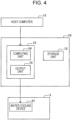
- Fig. 4 is a schematic diagram illustrating an example of the structure of the control device 10.
- the control device 10 is an information processing device, such as a personal computer.
- the control device 10 receives, from the host computer 11, the molten steel temperature, the size information, such as the thickness, of the cast steel S, and information regarding the desired range of the amount of cooling required to achieve the desired material quality and the desired range of the cooling rate.
- the control device 10 calculates operating conditions of the steel continuous-casting machine 1 for achieving the desired amount of cooling and the desired cooling rate, and determines the operation parameters of the devices.
- the control device 10 includes the control unit 12 and the storage unit 13.
- the control unit 12 is, for example, a CPU that executes programs read from the storage unit 13 to cause the control unit 12 to function as the computing unit 14 and the output unit 15.
- the storage unit 13 is, for example, an information recording medium, such as a re-recordable flash memory, a hard disk that is built-in or connected with a data communication terminal, or a memory card, and a read/write device for the information recording medium.
- the storage unit 13 stores programs for causing the control unit 12 to execute the functions and data used by the programs.
- the computing unit 14 performs a heat transfer calculation based on an internal model to determine the number of cooling zones to be used, the amount of cooling water, the amount of compressed air, and the transportation speed of the cast steel S for achieving the desired amount of cooling and the desired cooling rate set as the cooling conditions.
- the thus determined command values of the amount of cooling water, the amount of compressed air, and the transportation speed of the cast steel S are output from the output unit 15 to the water cooling device 31.
- the water cooling device 31 Based on the command values of the amount of cooling water, the amount of compressed air, and the transportation speed of the cast steel S, the water cooling device 31 generates commands regarding the number of cooling water pumps to be operated and operating pressures thereof, the number of air compressors to be operated and operating pressures thereof, the number of headers disposed upstream of the cooling-water-discharging nozzles 32, the opening degree of the flow control valve, and the rotational speeds of the cast-steel support rolls 5, and determines the operating conditions of the water cooling device 31.
- One or more of the number of cooling zones to be used, the amount of cooling water, the amount of compressed air, and the transportation speed of the cast steel S may be determined in advance by using a table based on information such as the composition and size information of the cast steel S and the desired material quality, and transmitted to the water cooling device 31 as the commands.
- adjustment parameters are provided to allow the number of cooling zones to be used, the amount of cooling water, the amount of compressed air, and the transportation speed of the cast steel S to be varied in accordance with changes in conditions during the operation.
- molten steel produced in a refining apparatus at a location separate from the steel continuous-casting machine 1 is poured into the mold 2 through a tundish (not illustrated).
- the poured molten steel is cooled by the mold 2 and solidifies from the contact surface between the molten steel and the mold 2 toward the inner layer, so that the outer shell shape of the cast steel S is formed.
- the cast steel S extracted from the mold 2 is cooled by the cooling apparatus 3 while being supported and transported by the cast-steel support rolls 5 disposed at the exit side of the mold 2.
- the number of zones to be used, the amount of cooling water, the amount of compressed air, and the transportation speed are calculated and set by the control device 10 in accordance with the size of the cast steel S and the desired properties of the cast steel S.
- it is assumed that the cast steel S is cooled by discharging water and air in all the zones illustrated in Fig. 2 .
- a predetermined amount of cooling water W and a predetermined amount of compressed air A are discharged from 19 pairs of cooling-water-discharging nozzles 32, and the cast-steel support rolls 5 are rotated at a predetermined speed. These parameters are set by the control device 10 so that desired cast steel properties can be obtained, and are transmitted to the cooling-water-discharging nozzles 32 and the cast-steel support rolls 5.
- the cast steel S having the desired properties can be produced by cooling the cast steel S with the cooling apparatus 3. After the cooling step, the cast steel S is subjected to a subsequent process.
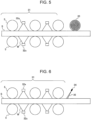
- Fig. 5 is a schematic partial sectional view of a steel continuous-casting machine including a water purging roll.
- a water purging roll 33 may be disposed at the exit side of the water cooling device 31 of the steel continuous-casting machine 1 to purge the cooling water W remaining on the cast steel S.
- the cast steel S can be prevented from being cooled in a partial or entire area by the cooling water W remaining on the cast steel S such that the desired amount of cooling cannot be obtained and that the desired properties cannot be obtained as a result in a partial or entire area.
- the pressing force that presses the water purging roll 33 against the cast steel S is preferably 4 tons or more.
- the pressing force that presses the water purging roll 33 against the cast steel S is more preferably 6 tons or more, and still more preferably 8 tons or more.
- the pressing force that presses the water purging roll 33 against the cast steel S is preferably 20 tons or less.
- a mechanism that applies the pressing force to the water purging roll 33 may be a spring-type mechanism, such as a spring, or a pneumatic or hydraulic mechanism capable of applying a constant pressing force.
- the mechanism is preferably capable of maintaining the pressing force constant, and is more preferably capable of changing the pressing force in the longitudinal direction of the cast steel S.
- the cast-steel support rolls 5 may serve as water purging rolls.
- the pressing force applied by the cast-steel support rolls 5 is not limited to the above-described ranges. This is because the quality of the cast steel may be improved by subjecting the cast steel S to rolling reduction by the cast-steel support rolls 5.
- Fig. 6 is a schematic partial sectional view of a steel continuous-casting machine including a purge nozzle.
- a purge nozzle 34 may be disposed instead of the water purging roll 33, and a water purging jet 35 is emitted to purge the cooling water W remaining on the cast steel S.
- the water purging jet 35 may be liquid, gas, or fluid of gas-liquid mixture.
- gas is preferably used as the water purging jet 35.
- air is used as the water purging jet 35.
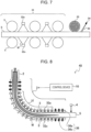
- Fig. 7 is a schematic partial sectional view of a steel continuous-casting machine including a water purging roll and a purge nozzle.
- the water purging roll 33 and the purge nozzle 34 may both be used.
- one or both of the water purging roll 33 and the purge nozzle 34 may be disposed at the entry side of the water cooling device 31 to purge the cooling water W that leaks from the water cooling device 31.
- a reduction in the temperature of the cast steel S that enters the cooling apparatus 3 can be suppressed, and the cooling water W can be prevented from entering another device (for example, the mold 2) disposed upstream of or around the cooling apparatus 3.
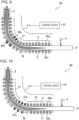
- Fig. 9 is a schematic sectional view illustrating another example of a steel continuous-casting machine according to the present embodiment.
- a steel continuous-casting machine 50 includes the cooling-water-discharging nozzles 32 and cooling-water-discharging nozzles 36 capable of discharging an amount of cooling water that changes the boiling state to the nucleate boiling state in the same cooling zones.
- the cooling-water-discharging nozzles 32 and the cooling-water-discharging nozzles 36 may be disposed in the same cooling zones.
- cooling-water-discharging nozzles 32 and the cooling-water-discharging nozzles 36 are combined, cooling with various temperature histories can be achieved.
- the cooling-water-discharging nozzles 32 and the cooling-water-discharging nozzles 36 are disposed in two zones in Fig. 9 , the number of zones is not limited to this, and may be other than 2.
- Fig. 10 is a schematic sectional view illustrating another example of a steel continuous-casting machine according to the present embodiment.
- a steel continuous-casting machine 60 includes cooling-water-discharging nozzles 37 that discharges only an amount of water that changes the boiling state to the nucleate boiling state in place of some of the cooling-water-discharging nozzles of the water cooling device 31.
- the cooling-water-discharging nozzles 37 may be provided in place of some of the cooling-water-discharging nozzles of the water cooling device 31.
- the cooling-water-discharging nozzles 36 capable of discharging an amount of water that changes the boiling state to the nucleate boiling state may be one-fluid nozzles that discharge only air, one-fluid nozzles that discharge only water, or two-fluid nozzles that discharge mixed fluid containing water and air.
- the cast-steel support rolls 5 are disposed on the first and third surfaces of the cast steel S.
- the cast-steel support rolls 5 are not limited to this, and may be disposed on the second and fourth surfaces.
- the second and fourth surfaces are supported and subjected to rolling reduction by the rolls, the expansion in the width direction resulting from the rolling reduction by the cast-steel support rolls 5 on the first and third surfaces can be suppressed.
- the cooling apparatus 3 included 19 pairs of cooling-water-discharging nozzles 32 constituting the water cooling device 31 and 20 pairs of cast-steel support rolls 5.
- the cooling-water-discharging nozzles 32 were structured such that rectangular spray nozzles, square spray nozzles, and circular spray nozzles were removably attachable and replaced in accordance with the casting conditions.
- the thermometer 4 was disposed at a position 5 m downstream from the exit of the cooling apparatus 3 to measure the surface-layer temperature distribution of the cast steel S in the width direction after the cast steel S passed through the cooling apparatus 3.
- a value obtained by subtracting the minimum value from the maximum value was evaluated as the temperature deviation in the cast steel S.
- the temperature deviation of less than 50°C was evaluated as acceptable.
- a slab produced by cutting the cast steel S was subjected to a subsequent process of follow-up inspection for small cracks on the surface of the slab.
- the number of segregated grains at the center of the cast steel in the thickness direction was counted.
- Table 1 shows the casting conditions and the evaluation results of the cast steel S according to Example.
- the angle is ⁇ 1 for a rectangular shape and ⁇ 2 for a square shape.
- the length is t 1 for a rectangular shape, t for a square shape, and the diameter D for a circular shape.
- the cast steel was evaluated as acceptable. A slab with high quality over the entire width and length was obtained, and no defects were found on the steel strip after cold rolling; the resulting product was shippable. In Invention Example 4, no defects were found on the steel strip after cold rolling, and the temperature deviation was less than 50°C. However, the temperature deviation was greater than that for Invention Example 2. This may be because since the discharge angle ⁇ 1 was increased, the velocity component of the spray water in the transport direction was increased, and the cooling water discharged toward the cast steel was not quickly removed to the outside of the cast steel, resulting in the occurrence of local subcooling portions.
- the temperature deviation in the width direction was smaller when the rectangular spray nozzles were used than when the circular or square spray nozzles were used. This may be because when the rectangular spray nozzles were used, the cooling water W discharged in the major-axis direction at a high flow rate was quickly removed to the outside of the cast steel S in the width direction.
- the temperature deviation was smallest when the spray nozzles having the spray discharge surfaces with an aspect ratio of 30 were used.
- the aspect ratio is low, the effect of removing the cooling water W is reduced.
- the aspect ratio is high, the local concentration of the cooling water W occurs, and the temperature deviation increases. This result shows that the aspect ratio of the spray discharge surfaces has an optimum value.
- Invention Examples 7 to 9 are examples in which casting was performed using rectangular, square, and circular spray nozzles and in which the water flow density was increased.
- the temperature deviation was less than 50°C and was acceptable, but several small cracks were found on the surface of the slab. The formation of small cracks may be because the cooling rate was excessively high and the surface layer of the cast steel S transformed into martensite.
- the temperature deviation was acceptable for Invention Examples 7 to 9, no defects were found on the steel strip after cold rolling, and the resulting product was shippable.
- Invention Examples 10 to 12 are examples in which casting was performed using rectangular, square, and circular spray nozzles and in which the water flow density was reduced.
- the temperature deviation was less than 50°C and was acceptable, but the number of segregated grains at the center of the cast steel in the thickness direction increased. The increase in the number of segregated grains at the center of the cast steel in the thickness direction may be because the cooling rate was excessively low and the temperature gradient in the cast steel S was reduced.
- the temperature deviation was acceptable for Invention Examples 10 to 12
- no defects were found on the steel strip after cold rolling, and the resulting product was shippable.
- Comparative Example 1 is an example in which casting was performed using flat spray nozzles, and the discharge angle was reduced such that Inequality (1) above was not satisfied.
- the temperature deviation was 90°C.
- the quality of the produced slab was not uniform over the entire width, and defects were found on the steel strip after rolling. Therefore, the steel strip produced from this slab was not shippable. This may be because the sprays of the cooling water W discharged from adjacent nozzles interfered with each other, causing a disruption of the film boiling state and an increase in the cooling capacity in that region.
- Comparative Example 2 is an example in which casting was performed using rectangular spray nozzles, and the discharge angle was increased such that Inequality (1) above was not satisfied.
- the temperature deviation was 218°C.
- the quality of the produced slab was not uniform over the entire width, and defects were found on the steel strip after rolling. Therefore, the steel strip produced from this slab was not shippable. This may be because the cooling water W on the cast steel S was not removed to the outside of the cast steel S in the width direction and remained on the cast steel S, causing a local transition from the film boiling state to the nucleate boiling state.
- Comparative Examples 3 and 4 are examples in which square or circular spray nozzles were used and in which the nozzle arrangement interval was reduced such that Inequality (2) or (3) above was not satisfied.
- the temperature deviation was 86°C and 92°C, respectively.
- the quality of the produced slab was not uniform over the entire width, and defects were found on the steel strip after cold rolling. Therefore, the steel strip produced from this slab was not shippable. This may be because the sprays of the cooling water W discharged from adjacent spray nozzles interfered with each other, causing an increase in the cooling capacity in that region.
Landscapes
- Engineering & Computer Science (AREA)
- Mechanical Engineering (AREA)
- Continuous Casting (AREA)
Abstract
Description
- The present invention relates to a steel continuous-casting machine and a steel continuous-casting method.
- In a steel continuous-casting process, molten steel poured into a mold is cooled, and cast steel extracted from the mold is transported while being cooled at the exit side of the mold. Thus, cast steel is continuously produced. Then, the cast steel is cut into predetermined lengths to produce slabs, blooms, and billets as rolling materials.
- The cast steel extracted from the mold has unsolidified molten steel therein. The unsolidified molten steel is solidified to the center by being cooled at the exit side of the mold. The properties and quality of the cast steel vary depending on the solidification rate. Therefore, cooling at the exit side of the mold (hereinafter referred to as secondary cooling) is a process that determines the properties and quality of the cast steel.
- In recent years, the properties and uniformity required of steel materials have become increasingly stringent. Accordingly, the quality requirements for slabs, blooms, and billets have been increasing year by year, and cast steel of high quality over the entire length and width is required. Therefore, in the continuous-casting process, particularly in secondary cooling, uniform cooling over the entire width of the cast steel has become more important than ever.
-
Fig. 1 is a graph showing the relationship between the surface temperature of cast steel and the boiling state in a water cooling process for the cast steel. As illustrated inFig. 1 , in the initial stage of water cooling, the cast steel is cooled in a film boiling state in which a vapor film is present between the cast steel and water. In the film boiling state, the water and the cast steel do not come into direct contact with each other, so that the heat transfer coefficient, which is an index of cooling capacity, is low and the surface temperature of the cast steel decreases slowly. However, when the surface temperature of the cast steel is reduced to about 700°C, it becomes difficult to maintain the vapor film between the water and the cast steel, and the cast steel is cooled in a transition boiling state in which the water and the cast steel are partially in contact with each other. When the water and the cast steel come into contact, the flow of the water near the cast steel intensifies due to the evaporation of the water that has come into contact with the cast steel. Therefore, the heat transfer coefficient rapidly increases, and the surface temperature of the cast steel rapidly drops. After that, the boiling state changes to a nucleate boiling state in which the cast steel and the water are steadily in contact with each other while the high heat transfer coefficient is maintained, and the surface temperature of the cast steel rapidly drops to a temperature close to the water temperature. - In general, as the temperature of the object to be cooled is high, transition to the nucleate boiling state is less likely to occur, and a larger amount of cooling water is required to induce the transition. This leads to a higher production cost. In addition, when a high-temperature object is cooled in the nucleate boiling state in which the cooling capacity is high, the surface and interior of the object receive a high thermal stress, and the risk of defects, such as cracks, increases. Therefore, in secondary cooling of the continuous-casting process, in which the cast steel has a high surface temperature, the cast steel is generally cooled in the film boiling state in which the vapor film is provided between the cast steel and the water.
- In light of the above discussion, the film boiling state is preferably maintained over the entire width during the secondary cooling in the continuous-casting process. When the vapor film is disrupted locally or entirely, the transition to the nucleate boiling state, in which the cooling capacity is high, occurs. This leads to an increase in the temperature deviation between a region in the film boiling state and a region in the nucleate boiling state or an excessive cooling rate. As a result, cast steel having high and uniform quality over the entire width cannot be produced.
- The disruption of the film boiling state may be caused by, for example, a local increase in the water flow density, stagnation of the cooling water on the upper surface of the cast steel, or collision of sprays of cooling water discharged from adjacent sprays. To produce cast steel with uniform quality over the entire width, efforts have been made to avoid the above-described causes and maintain the film boiling state.
- The local increase in the water flow density may be suppressed by improving tip portions of nozzles that discharge the cooling water and making the distribution of the cooling water discharged toward the cast steel uniform. It is also effective to use nozzles having spray discharge surfaces with a low aspect ratio and a large discharge area to reduce the local concentration of the cooling water. When the spray discharge surfaces are rectangular, the aspect ratio is the ratio of the short-side length to the long-side length. When the spray discharge surfaces are elliptical, the aspect ratio is the ratio of the minor axis to the major axis. When the spray discharge surfaces are square or circular, the aspect ratio is 1.
-
Patent Literature 1 describes a technique for suppressing the stagnation of the cooling water on the cast steel. In this technique, the cooling water is discharged as sprays having central axes at an angle relative to the central axes of the nozzles, so that the cooling water present between roll pairs that support and convey the cast steel is efficiently removed to the outside of the zones, and that the film boiling state can be maintained.Patent Literature 2 describes a technique for suppressing the collision of the sprays of cooling water. In this technique, the cooling water is discharged such that the major axes of the spray discharge surfaces are at an angle θ or 5° of more and less than 45° relative to the width direction of the cast steel, so that the collision of the sprays of cooling water discharged from the adjacent sprays is avoided, and that the film boiling state can be maintained. -
- PTL 1: International Publication No.
2018/101287 - PTL 2:
Japanese Unexamined Patent Application Publication No. 2009-255127 - An object of the technology disclosed in
Patent Literature 1 is to prevent stagnant water from flowing to a region downstream of a vertical section and a curved section in a continuous-casting machine having the vertical section and the curved section. The technology disclosed inPatent Literature 1 is not sufficient to remove the stagnant cooling water on the cast steel in a horizontal section in which the cast steel surface layer temperature is reduced and the film boiling state is easily disrupted. In addition, also in the vertical section and the curved section, when the cooling water is simply discharged upward to prevent the cooling water from flowing downstream, stagnation of the water occurs between the roll pairs, and the temperature deviation in the width direction increases. Therefore, also in the vertical section and the curved section, a technique for smoothly removing the cooling water discharged toward the cast steel to the outside of the cast steel in the width direction is required. - Also, when the technology disclosed in
Patent Literature 2 is used, the collision of the sprays of cooling water discharged from the adjacent nozzles may occur if low-aspect-ratio sprays effective in spreading the water flow distribution and maintaining the film boiling state are used. In addition, even when high-aspect-ratio spray nozzles are used, the collision of the sprays of cooling water occurs if the distances between the spray nozzles are small. As a result, the disruption of the film boiling state may be accelerated. - The present invention has been made in light of the above-described problems, and an object of the present invention is to provide a steel continuous-casting machine and a steel continuous-casting method capable of suppressing the collision of sprays of cooling water discharged from spray nozzles adjacent to each other in a width direction of cast steel and the disruption of a film boiling state.
- Means for solving the above-described problems are as follows:
- [1] A steel continuous-casting machine including a cooling apparatus that cools cast steel with water, wherein the cooling apparatus includes two or more cooling-water-discharging nozzles arranged in a width direction of the cast steel, and wherein the two or more cooling-water-discharging nozzles are arranged such that spray discharge surfaces of cooling-water-discharging nozzles adjacent to each other in the width direction of the cast steel do not overlap.
- [2] The steel continuous-casting machine according to [1], wherein the spray discharge surfaces of the cooling-water-discharging nozzles are rectangular or elliptical, and wherein each of the two or more cooling-water-discharging nozzles is disposed to satisfy Inequality (1) below:
[Math. 1]
- [3] The steel continuous-casting machine according to [1], wherein the spray discharge surfaces of the cooling-water-discharging nozzles are square, and wherein each of the two or more cooling-water-discharging nozzles is disposed to satisfy Inequality (2) below:

- [4] The steel continuous-casting machine according to [1], wherein the spray discharge surfaces of the cooling-water-discharging nozzles are circular, and wherein each of the two or more cooling-water-discharging nozzles is disposed to satisfy Inequality (3) below:

- [5] The steel continuous-casting machine according to [2], wherein an aspect ratio of the spray discharge surface is 100 or less.
- [6] The steel continuous-casting machine according to any one of [1] to [5], wherein a surface-layer cooling rate of the cast steel in the cooling apparatus is in a range of 0.3°C/sec or more and 100°C/sec or less.
- [7] The steel continuous-casting machine according to any one of [1] to [6], further including a control device that controls an amount of cooling water discharged from the cooling-water-discharging nozzles and a transportation speed of the cast steel.
- [8] A steel continuous-casting method including a cooling step of cooling cast steel with water, wherein, in the cooling step, the cast steel is cooled by discharging cooling water from two or more cooling-water-discharging nozzles arranged in a width direction of the cast steel, and wherein the two or more cooling-water-discharging nozzles are arranged such that spray discharge surfaces of cooling-water-discharging nozzles adjacent to each other in the width direction of the cast steel do not overlap.
- [9] The steel continuous-casting method according to [8], wherein the spray discharge surfaces of the cooling-water-discharging nozzles are rectangular or elliptical, and wherein each of the two or more cooling-water-discharging nozzles is disposed to satisfy Inequality (1) below:
[Math. 2]
- [10] The steel continuous-casting method according to [8], wherein the spray discharge surfaces of the cooling-water-discharging nozzles are square, and wherein each of the two or more cooling-water-discharging nozzles is disposed to satisfy Inequality (2) below:

- [11] The steel continuous-casting method according to [8], wherein the spray discharge surfaces of the cooling-water-discharging nozzles are circular, and wherein each of the two or more cooling-water-discharging nozzles is disposed to satisfy Inequality (3) below:

- [12] The steel continuous-casting method according to [9], wherein an aspect ratio of the spray discharge surface is 100 or less.
- [13] The steel continuous-casting method according to any one of [8] to [12], wherein a surface-layer cooling rate of the cast steel in the cooling step is in a range of 0.3°C/sec or more and 100°C/sec or less.
- [14] The steel continuous-casting method according to any one of [8] to [13], wherein, in the cooling step, at least one of a surface-layer cooling rate of the cast steel and a temperature drop of the cast steel is controlled by controlling an amount of cooling water discharged from the cooling-water-discharging nozzles and a transportation speed of the cast steel.
- According to the present invention, the collision of sprays of cooling water discharged from spray nozzles that are adjacent to each other in the width direction of the cast steel can be suppressed. Therefore, the disruption of the film boiling state is suppressed when the cast steel is subjected to secondary cooling, and the temperature deviation on the surface of the cast steel being cooled can be reduced, so that cast steel with fewer defects can be produced by continuous casting.
-
- [
Fig. 1] Fig. 1 is a graph showing the relationship between the surface temperature of cast steel and the boiling state in a water cooling process for the cast steel. - [
Fig. 2] Fig. 2 is a schematic sectional view of a steel continuous-casting machine according to an embodiment of the present invention. - [
Fig. 3] Fig. 3 illustrates spray discharge surfaces of cooling water discharged from cooling-water-discharging nozzles on cast steel S. - [
Fig. 4] Fig. 4 is a schematic diagram illustrating an example of the structure of acontrol device 10. - [
Fig. 5] Fig. 5 is a schematic partial sectional view of a steel continuous-casting machine including a water purging roll. - [
Fig. 6] Fig. 6 is a schematic partial sectional view of a steel continuous-casting machine including a purge nozzle. - [
Fig. 7] Fig. 7 is a schematic partial sectional view of a steel continuous-casting machine including a water purging roll and a purge nozzle. - [
Fig. 8] Fig. 8 is a schematic sectional view illustrating another example of a steel continuous-casting machine according to the present embodiment. - [
Fig. 9] Fig. 9 is a schematic sectional view illustrating another example of a steel continuous-casting machine according to the present embodiment. - [
Fig. 10] Fig. 10 is a schematic sectional view illustrating another example of a steel continuous-casting machine according to the present embodiment. - The present invention will now be described by means of embodiments of the present invention. The embodiments described below illustrate devices and methods for embodying the technical idea of the present invention. In the technical idea of the present invention, materials, shapes, structures, arrangements, and the like of constituent parts are not limited to those in the embodiments described below. The drawings are schematic, and therefore it is to be noted that the relationships, ratios, and the like between the thicknesses and the planar dimensions are different from the actual ones. The drawings may also differ from each other in dimensional relationships and ratios.
-
Fig. 2 is a schematic sectional view of a steel continuous-casting machine according to an embodiment of the present invention. The main components of a steel continuous-castingmachine 1 according to the embodiment of the present invention include amold 2 that cools molten steel poured from a tundish (not illustrated) and form an outer shell shape of cast steel; acooling apparatus 3 that cools the cast steel extracted from the mold; athermometer 4 that measures a temperature of the cast steel at the exit side of thecooling apparatus 3; and acontrol device 10 that controls the operation of thecooling apparatus 3. In the following description, a long-side surface of the cast steel at the upper right inFig. 2 is referred to as a first surface, a short-side surface at the near side as a second surface, a long-side surface at the lower left side as a third surface, and a short-side surface at the far side as a fourth surface. - The molten steel is produced in a refining apparatus at a location separate from the steel continuous-casting
machine 1, and is poured into themold 2. The molten steel poured into themold 2 is cooled by themold 2 so that the molten steel solidifies from the contact surface between the molten steel and themold 2 toward an inner layer and that the outer shell shape is formed. In the following description, the molten steel whose outer shell shape is formed, including completely solidified steel, is referred to as cast steel S. The cast steel S extracted from themold 2 is cooled by thecooling apparatus 3 while being supported and transported by cast-steel support rolls 5 provided at the exit side of themold 2. A commonly known mold may be used as themold 2. - The
cooling apparatus 3 includes awater cooling device 31 that cools the cast steel S with water under predetermined cooling conditions. Thewater cooling device 31 includes the cast-steel support rolls 5 that support and transport the cast steel S, and cooling-water-dischargingnozzles 32. The cast-steel support rolls 5 on the first-surface side and the third-surface side of the cast steel S form pairs and are arranged with equal intervals in the casting direction. At positions between the cast-steel support rolls 5 adjacent to each other in the casting direction, two or more cooling-water-dischargingnozzles 32a on the first-surface side and two or more cooling-water-dischargingnozzles 32c on the third-surface side form pairs across the cast steel S and are arranged at a predetermined interval in the casting direction. The cooling-water-dischargingnozzles 32 discharge cooling water W toward the cast steel S. The cast steel S is fed into thecooling apparatus 3, so that the cast steel S is transported in the casting direction while being cooled by the cooling water W discharged from the cooling-water-dischargingnozzles 32 in the secondary cooling process. In the following description, a cooling section in which one pair of cast-steel support rolls 5 in the casting direction serves as a unit is referred to as a cooling zone, and cooling sections will be counted in units of "zones". Although a total of 19 zones are provided as the cooling zones inFig. 2 , the number of zones is not limited to this, and may be greater or smaller than 19. - The steel continuous-casting
machine 1 illustrated inFig. 2 is a vertical-bending continuous-casting machine, and is characterized in that thecooling apparatus 3 is constituted by a vertical section 6 in which the cast steel S extracted from themold 2 and orientated vertically is cooled with water; a curved section 7 in which the cast steel S is cooled with water while being curved by the cast-steel support rolls 5; and ahorizontal section 8 in which the cast steel S is cooled with water after being curved to extend horizontally by the cast-steel support rolls 5. Although the vertical-bending continuous-casting machine will be described as an example in the present embodiment, the continuous-casting machine is not limited to a vertical-bending continuous-casting machine, and may be a vertical continuous-casting machine including only the vertical section 6 in thecooling apparatus 3, a curved continuous-casting machine including only the curved section 7 and thehorizontal section 8, or a horizontal continuous-casting machine including only thehorizontal section 8. - Operation parameters of the
water cooling device 31 include the amount of cooling water W (amount of cooling water) and the amount of compressed air discharged from the cooling-water-dischargingnozzles 32 and the transportation speed at which the cast steel S is transported. As the amount of cooling water increases, the cooling rate and the temperature drop of the cast steel S increase. As the transportation speed of the cast steel S decreases, the temperature drop of the cast steel S increases. Therefore, at least one of the surface-layer cooling rate and the temperature drop of the cast steel S can be controlled by controlling at least one of the transportation speed of the cast steel S and the amount of cooling water, and the cast steel S having the desired material quality can be produced. In addition, the cooling capacity and the surface distribution of the cooling water W can be adjusted by adding the compressed air to the cooling water W discharged from the cooling-water-dischargingnozzles 32. The desired properties, deterioration of the machine over time, and small changes in the nozzle arrangement may also be controlled under appropriate conditions by adjusting the amount of compressed air. - The balance between the amounts of cooling water in the cooling zones may be changed as an operation parameter of the water cooling device 31 (for example, the amount of cooling water may be increased in upstream cooling zones and reduced in downstream cooling zones). Thus, the cooling rate can be controlled for each temperature range of the cast steel S. In addition, the number of cooling zones in which the cooling water is discharged may be changed. The temperature drop of the cast steel S can be controlled while the cooling rate is maintained constant by changing the number of cooling zones that are used.
- Furthermore, the ratio between the amount of cooling water W discharged from the cooling-water-discharging
nozzles 32a on the first-surface side and the amount of cooling water W discharged from the cooling-water-dischargingnozzles 32c on the third-surface side can be changed. Accordingly, shape defects due to the difference in the temperature drop between the first surface and the third surface of the cast steel S can be controlled. In addition, the amount of cooling water can be changed in accordance with the composition of the cast steel S. This is because the thermal conductivity of the cast steel S changes in accordance with the composition of the cast steel S, and the cooling state changes accordingly. When the amount of cooling water is changed, the amount of compressed air and the transportation speed of the cast steel S may also be changed. The cooling capacity and the surface distribution of the cooling water W may be controlled by changing the amount of compressed air, and the temperature history of the cast steel S may be controlled by changing the transportation speed of the cast steel S. Thus, the cooling conditions can be finely adjusted, thereby improving the quality of the cast steel. - The operation parameters of the
water cooling device 31 may be changed as the casting proceeds. In particular, the leading and trailing end portions of the cast steel S are additionally cooled from the leading and trailing end faces and therefore tend to become nonstationary portions. Therefore, the operation parameters of thewater cooling device 31 may be finely adjusted for these portions, so that high quality can be ensured over the entire length and width and the yield in the nonstationary portions can be increased. - The operation parameters of the
water cooling device 31 may also be finely adjusted for the stationary portion excluding the leading and trailing end portions as the casting proceeds. When, for example, the properties of the stationary portion vary in the longitudinal direction due to the composition segregation of the cast steel S, the cast steel having a uniform quality over the entire length can be obtained by finely adjusting the operation parameters of thewater cooling device 31. - The cooling rate is preferably variable in accordance with the material, operating conditions, and the machine status. When the surface-layer cooling rate exceeds 100°C/sec, the surface layer is often transformed into martensite, causing defects, such as cracks, on the surface of the cast steel. Therefore, the surface-layer cooling rate is preferably less than or equal to 100°C/sec. When the surface-layer cooling rate is less than 0.3°C/sec, the cooling rate is substantially equal to that in the case where the cast steel is allowed to be naturally cooled, and the production efficiency is reduced. In addition, as the cooling rate decreases, the segregation in the cast steel is increased, and the quality of the cast steel is degraded. Therefore, the surface-layer cooling rate is preferably greater than or equal to 0.3°C/sec.
- As is clear from the graph illustrated in
Fig. 1 , the film boiling state eventually transitions to the nucleate boiling state. Therefore, discharging of the cooling water W toward the cast steel S is to be stopped while the temperatures of the front and back surfaces of the cast steel S are 500°C or higher, preferably 600°C or higher. When the temperatures of the front and back surfaces of the cast steel S are sufficiently increased due to internal recuperation after the cooling water W is discharged, the cooling water W may be discharged again. When the cooling rate is increased by discharging the cooling water W again, the production efficiency can be increased and the quality of the cast steel can be improved. - Nozzles capable of uniformly discharging cooling water at a predetermined flow rate are preferably used as the cooling-water-discharging
nozzles 32. Although spray nozzles are used as the cooling-water-dischargingnozzles 32 in the present embodiment, the cooling-water-dischargingnozzles 32 are not limited to spray nozzles, and may be slit-type nozzles, multi-hole jet nozzles, mist nozzles, or fog nozzles. The cooling-water-dischargingnozzles 32 may be either one-fluid nozzles that discharge only liquid (generally water) or two-fluid nozzles that discharge mixed fluid containing liquid (generally water) and gas (generally air) . - Nozzles that discharge only air does not cause a transition of the boiling state, but may be disposed at positions near or slightly displaced from the cooling-water-discharging
nozzles 32. These nozzles may discharge air to improve drainage or for water purging. In addition, the cooling-water-dischargingnozzles 32 are preferably capable of varying the amount of cooling water and the amount of compressed air in accordance with the desired cooling rate. - When the cooling water W discharged from the cooling-water-discharging
nozzles 32 comes into contact with the cast steel S such that collision of the sprays of the cooling water W discharged from the adjacent cooling-water-dischargingnozzles 32 occurs on the cast steel S, horizontal momentum changes to vertical momentum at the collision point, and the downward component of the vertical flow breaks the vapor film and causes a local disruption of the film boiling state. When the spray has a rectangular spray discharge surface, the horizontal component of the moment of the cooling water W discharged in the long-side direction is greater than that of the cooling water W discharged in the short-side direction. Therefore, collision of the sprays of the cooling water W discharged from the adjacent cooling-water-dischargingnozzles 32 in the long-side direction needs to be avoided. -
Fig. 3 illustrates spray discharge surfaces on the cast steel S toward which the cooling water is discharged from the cooling-water-discharging nozzles.Fig. 3(a) illustrates rectangular spray discharge surfaces. Assume that the cooling-water-dischargingnozzles 32 are such that the spray discharge surfaces on the cast steel S have a rectangular shape with short sides having a length of t1 (m) and long sides having a length of t2 (m). Due to the geometric relationship, to avoid the collision of the spray discharge surfaces in the long-side direction, the cooling-water-dischargingnozzles 32 need to be placed such that the spray discharge surfaces of the cooling-water-dischargingnozzles 32 adjacent to each other in the width direction of the cast steel S do not overlap. More specifically, the cooling-water-dischargingnozzles 32 are arranged such that the arrangement interval of the cooling-water-dischargingnozzles 32 adjacent to each other in the width direction of the cast steel S, the angle of the long-side direction relative to the width direction of the cast steel, and the length of the short sides of the spray discharge surfaces are in the ranges that satisfy Inequality (1) below. When the cooling-water-dischargingnozzles 32 are arranged such that Inequality (1) below is satisfied, collision in the long-side direction of the sprays of the cooling water W discharged from the cooling-water-dischargingnozzles 32 adjacent to each other in the width direction of the cast steel S can be suppressed, so that the disruption of the film boiling state can be suppressed. This also applies to the cooling-water-discharging nozzles whose spray discharge surfaces on the cast steel S are elliptical. In such a case, in Inequality (1) below, the long-side direction may be changed to the major-axis direction, and the length of the short sides may be changed to the length of the minor axis.
[Math. 3]
- In Inequality (1) above, L is the arrangement interval (m) of the cooling-water-discharging nozzles, θ1 is the angle (°) of the long-side direction of the spray discharge surface relative to the width direction of the cast steel, and t1 is the length (m) of the short sides of the spray discharge surfaces.
- When the spray discharge surfaces on the cast steel S are rectangular or elliptical, the aspect ratio of the discharge surfaces is preferably 100 or less. When sprays having the spray discharge surfaces with a low aspect ratio are used, the spray discharge surfaces can be broadened, and the local concentration of the cooling water can be suppressed, so that the film boiling state can be maintained longer. The aspect ratio of the spray discharge surfaces is more preferably 50 or less, and still more preferably 30 or less.
- When nozzles having the long sides of the same length are used to discharge the same amount of water, the nozzles preferably have a low aspect ratio and a long minor-axis dimension. When the nozzles have a low aspect ratio and short sides that are long, the area of the spray discharge surfaces is increased. Therefore, the water flow density is reduced and the local concentration of the cooling water can be suppressed. When the aspect ratio is too low, the amount of water that flows in the major-axis direction of the sprays is reduced, and the cooling water W easily remains on the cast steel S. Therefore, the aspect ratio is preferably two or more, more preferably 5 or more, and still more preferably 10 or more.
- The angle θ1 of the long-side direction is preferably less than 45° so that the cooling water W discharged toward the cast steel S can be quickly removed to the outside of the cast steel. The angle θ1 of the long-side direction of 45° or more is not preferable because when the velocity of the cooling water W in the long-side direction is resolved into the transport direction of the cast steel and the width direction of the cast steel, the component in the transport direction is greater than the component in the width direction of the cast steel. More preferably, the angle θ1 of the long-side direction is 30° or less.
-
Fig. 3(b) illustrates square spray discharge surfaces. When the spray discharge surfaces on the cast steel S are square, collision of the sprays of cooling water can be suppressed by arranging the cooling-water-dischargingnozzles 32 such that the arrangement interval of the cooling-water-dischargingnozzles 32 adjacent to each other in the width direction of the cast steel S, the angle of the direction of one side of each spray discharge surface relative to the width direction of the cast steel, and the length of one side of each spray discharge surface are in the ranges that satisfy Inequality (2) below.
- In Inequality (2) above, L is the arrangement interval (m) of the cooling-water-discharging
nozzles 32, θ2 is the angle (°) of the direction of one side of each spray discharge surface relative to the width direction of the cast steel, and t is the length (m) of one side of each spray discharge surface. Here, one side of each spray discharge surface is one of the sides of the spray discharge surface that is closest to an adjacent spray discharge surface. More specifically, in aspray discharge surface 20 illustrated inFig. 3(b) , the direction of one side is the direction of aside 21 that is closest to an adjacentspray discharge surface 22. In thespray discharge surface 22, the direction of one side is the direction of one ofsides -
Fig. 3(c) illustrates circular spray discharge surfaces. When the spray discharge surfaces on the cast steel S are circular, collision of the sprays of cooling water can be suppressed by arranging the cooling-water-dischargingnozzles 32 such that the arrangement interval of the cooling-water-dischargingnozzles 32 adjacent to each other in the width direction of the cast steel S and the diameter of the spray discharge surfaces are in the ranges that satisfy Inequality (3) below.
- In Inequality (3) above, L is the arrangement interval (m) of the cooling-water-discharging
nozzles 32, and D is the diameter (m) of the spray discharge surfaces. - The level of local concentration of the cooling water can be evaluated by the water flow density defined as flow rate/discharge area. Since the water flow density of the discharged cooling water and the boiling transition temperature are positively correlated, the film boiling state can be maintained longer by reducing the water flow density. With regard to the local water flow density of the cooling water in the steel continuous-casting
machine 1, to stabilize the film boiling state, the water flow density of the cooling water is preferably 1000 L/(m2×min) or less, more preferably 800 L/(m2×min) or less, and still more preferably 600 L/(m2×min) or less. - The
thermometer 4 may be a device that scans the cast steel S in the width direction to measure the surface temperature of the cast steel S, or be one or more devices arranged in the width direction of the cast steel S to measure the surface temperature of the cast steel S. It can be checked whether the cast steel S is cooled as expected by measuring the surface temperature of the cast steel S cooled by thecooling apparatus 3 by using thethermometer 4. - Referring to
Fig. 2 again, although thethermometer 4 is disposed at the exit side of thecooling apparatus 3 inFig. 2 , thethermometer 4 may be disposed in thecooling apparatus 3 when the temperature of the steel sheet that has been cooled by thewater cooling device 31 can be measured. In such a case,multiple thermometers 4 may be arranged next to each other in the transport direction of the cast steel S to measure the temperature of the cast steel S in each cooling zone. - In addition, the
thermometer 4 may be disposed at the entry side of thecooling apparatus 3 and the entry side of themold 2 to measure the initial temperature of the cast steel S and the temperature of the molten steel that is poured. This is because the accuracy of the calculation of the cooling rate can be increased by additionally taking into account the result of the temperature measurement at the entry side of thecooling apparatus 3. One ormore thermometers 4 may be disposed in thecooling apparatus 3 to measure the temperature of the cast steel S during water cooling. When the result of the temperature measurement in thecooling apparatus 3 is additionally taken into account, the accuracy of the calculation of the cooling rate can be increased and the time history of the cooling rate can be obtained. - The temperature information of the molten steel and the result of the temperature measurement of the cast steel S may be used in heat transfer calculation or heat transfer simulation to calculate the cooling rate during water cooling and check whether the cast steel S is being cooled as expected. In addition, the temperature distribution along the surfaces of the cast steel S during or after water cooling may be measured to check whether the cast steel S is uniformly cooled. Furthermore, the temperature distribution along the surfaces of the cast steel S before water cooling may be measured to check whether the temperature distribution along the surfaces of the cast steel S that enters the
cooling apparatus 3 is uniform. The operation parameters of thecooling apparatus 3 and the operating conditions of the steel continuous-castingmachine 1 may be changed based on the above-described calculation results. - The
control device 10 will now be described.Fig. 4 is a schematic diagram illustrating an example of the structure of thecontrol device 10. Thecontrol device 10 is an information processing device, such as a personal computer. Thecontrol device 10 receives, from thehost computer 11, the molten steel temperature, the size information, such as the thickness, of the cast steel S, and information regarding the desired range of the amount of cooling required to achieve the desired material quality and the desired range of the cooling rate. Thecontrol device 10 calculates operating conditions of the steel continuous-castingmachine 1 for achieving the desired amount of cooling and the desired cooling rate, and determines the operation parameters of the devices. - The
control device 10 includes thecontrol unit 12 and thestorage unit 13. Thecontrol unit 12 is, for example, a CPU that executes programs read from thestorage unit 13 to cause thecontrol unit 12 to function as thecomputing unit 14 and theoutput unit 15. Thestorage unit 13 is, for example, an information recording medium, such as a re-recordable flash memory, a hard disk that is built-in or connected with a data communication terminal, or a memory card, and a read/write device for the information recording medium. Thestorage unit 13 stores programs for causing thecontrol unit 12 to execute the functions and data used by the programs. - The
computing unit 14 performs a heat transfer calculation based on an internal model to determine the number of cooling zones to be used, the amount of cooling water, the amount of compressed air, and the transportation speed of the cast steel S for achieving the desired amount of cooling and the desired cooling rate set as the cooling conditions. The thus determined command values of the amount of cooling water, the amount of compressed air, and the transportation speed of the cast steel S are output from theoutput unit 15 to thewater cooling device 31. Based on the command values of the amount of cooling water, the amount of compressed air, and the transportation speed of the cast steel S, thewater cooling device 31 generates commands regarding the number of cooling water pumps to be operated and operating pressures thereof, the number of air compressors to be operated and operating pressures thereof, the number of headers disposed upstream of the cooling-water-dischargingnozzles 32, the opening degree of the flow control valve, and the rotational speeds of the cast-steel support rolls 5, and determines the operating conditions of thewater cooling device 31. - One or more of the number of cooling zones to be used, the amount of cooling water, the amount of compressed air, and the transportation speed of the cast steel S may be determined in advance by using a table based on information such as the composition and size information of the cast steel S and the desired material quality, and transmitted to the
water cooling device 31 as the commands. Preferably, adjustment parameters are provided to allow the number of cooling zones to be used, the amount of cooling water, the amount of compressed air, and the transportation speed of the cast steel S to be varied in accordance with changes in conditions during the operation. - A steel continuous-casting method using the steel continuous-casting
machine 1 illustrated inFig. 2 will now be described. First, molten steel produced in a refining apparatus at a location separate from the steel continuous-castingmachine 1 is poured into themold 2 through a tundish (not illustrated). The poured molten steel is cooled by themold 2 and solidifies from the contact surface between the molten steel and themold 2 toward the inner layer, so that the outer shell shape of the cast steel S is formed. - The cast steel S extracted from the
mold 2 is cooled by thecooling apparatus 3 while being supported and transported by the cast-steel support rolls 5 disposed at the exit side of themold 2. In a cooling step, the number of zones to be used, the amount of cooling water, the amount of compressed air, and the transportation speed are calculated and set by thecontrol device 10 in accordance with the size of the cast steel S and the desired properties of the cast steel S. In the present embodiment, it is assumed that the cast steel S is cooled by discharging water and air in all the zones illustrated inFig. 2 . - A predetermined amount of cooling water W and a predetermined amount of compressed air A are discharged from 19 pairs of cooling-water-discharging
nozzles 32, and the cast-steel support rolls 5 are rotated at a predetermined speed. These parameters are set by thecontrol device 10 so that desired cast steel properties can be obtained, and are transmitted to the cooling-water-dischargingnozzles 32 and the cast-steel support rolls 5. The cast steel S having the desired properties can be produced by cooling the cast steel S with thecooling apparatus 3. After the cooling step, the cast steel S is subjected to a subsequent process. - Although an embodiment of the present invention is described above, the present invention is not limited to this, and various alterations and modifications are possible.
Fig. 5 is a schematic partial sectional view of a steel continuous-casting machine including a water purging roll. As illustrated inFig. 5 , awater purging roll 33 may be disposed at the exit side of thewater cooling device 31 of the steel continuous-castingmachine 1 to purge the cooling water W remaining on the cast steel S. Thus, the cast steel S can be prevented from being cooled in a partial or entire area by the cooling water W remaining on the cast steel S such that the desired amount of cooling cannot be obtained and that the desired properties cannot be obtained as a result in a partial or entire area. - To achieve good purging performance, the pressing force that presses the
water purging roll 33 against the cast steel S is preferably 4 tons or more. The pressing force that presses thewater purging roll 33 against the cast steel S is more preferably 6 tons or more, and still more preferably 8 tons or more. When the pressing force that presses thewater purging roll 33 against the cast steel S is excessively increased, thewater purging roll 33 is bent by elastic deformation, and a gap is formed between the cast steel S and thewater purging roll 33, resulting in degradation of the purging performance. Therefore, the pressing force that presses thewater purging roll 33 against the cast steel S is preferably 20 tons or less. - A mechanism that applies the pressing force to the
water purging roll 33 may be a spring-type mechanism, such as a spring, or a pneumatic or hydraulic mechanism capable of applying a constant pressing force. To adjust the bending of thewater purging roll 33, the mechanism is preferably capable of maintaining the pressing force constant, and is more preferably capable of changing the pressing force in the longitudinal direction of the cast steel S. - The cast-steel support rolls 5 may serve as water purging rolls. In such a case, the pressing force applied by the cast-steel support rolls 5 is not limited to the above-described ranges. This is because the quality of the cast steel may be improved by subjecting the cast steel S to rolling reduction by the cast-steel support rolls 5.
-
Fig. 6 is a schematic partial sectional view of a steel continuous-casting machine including a purge nozzle. As illustrated inFig. 6 , apurge nozzle 34 may be disposed instead of thewater purging roll 33, and awater purging jet 35 is emitted to purge the cooling water W remaining on the cast steel S. Thewater purging jet 35 may be liquid, gas, or fluid of gas-liquid mixture. When liquid is used as thewater purging jet 35, the portion receiving the liquid may be cooled and the temperature deviation along the surface of the cast steel S may be increased. Therefore, gas is preferably used as thewater purging jet 35. To reduce production costs, more preferably, air is used as thewater purging jet 35. -
Fig. 7 is a schematic partial sectional view of a steel continuous-casting machine including a water purging roll and a purge nozzle. As illustrated inFig. 7 , thewater purging roll 33 and thepurge nozzle 34 may both be used. In addition, one or both of thewater purging roll 33 and thepurge nozzle 34 may be disposed at the entry side of thewater cooling device 31 to purge the cooling water W that leaks from thewater cooling device 31. In this case, a reduction in the temperature of the cast steel S that enters thecooling apparatus 3 can be suppressed, and the cooling water W can be prevented from entering another device (for example, the mold 2) disposed upstream of or around thecooling apparatus 3. - In addition, one or both of the
water purging roll 33 and thepurge nozzle 34 may be disposed not only at the entry and exit sides of thewater cooling device 31 but also at the entry and exit sides of each cooling zone to divide the cooling zones from each other. When the amount of water discharged differs between the cooling zones, the temperature history of the steel sheet can be determined by dividing the zones with different amounts of cooling water from each other. - It is not necessary that all of the cooling-water-discharging
nozzles 32 included in thecooling apparatus 3 satisfy Inequality (1), (2), or (3) above as long as two or more cooling-water-dischargingnozzles 32 adjacent to each other in the width direction of the cast steel satisfy Inequality (1), (2), or (3) above. In such a case, compared to a steel continuous-casting machine in which none of the cooling-water-dischargingnozzles 32 satisfy Inequality (1), (2), or (3) above, the collision of the sprays of cooling water can be further suppressed, so that the disruption of the film boiling state can be further suppressed. -
Fig. 8 is a schematic sectional view illustrating another example of a steel continuous-casting machine according to the present embodiment. Referring toFig. 8 , a steel continuous-castingmachine 40 includes cooling-water-dischargingnozzles 36 capable of discharging an amount of cooling water that changes the boiling state to the nucleate boiling state at both the entry and exit sides of thewater cooling device 31. The cooling-water-dischargingnozzles 36 are used to cool the cast steel S depending on the desired properties of the cast steel S. Thus, the cooling-water-dischargingnozzles 36 that discharge an amount of cooling water that changes the boiling state to the nucleate boiling state may be disposed at the entry and exit sides of thewater cooling device 31. Although the cooling-water-dischargingnozzles 36 are disposed at both the entry and exit sides of thewater cooling device 31 inFig. 8 , the cooling-water-dischargingnozzles 36 are not limited to this, and may be provided at one of the entry and exit sides. In addition, although the cooling-water-dischargingnozzles 36 are provided for three zones at the entry side and three zones at the exit side of thewater cooling device 31 inFig. 8 , the number of cooling zones for which the cooling-water-dischargingnozzles 36 are provided is not limited to this, and may be other than three. -
Fig. 9 is a schematic sectional view illustrating another example of a steel continuous-casting machine according to the present embodiment. Referring toFig. 9 , a steel continuous-castingmachine 50 includes the cooling-water-dischargingnozzles 32 and cooling-water-dischargingnozzles 36 capable of discharging an amount of cooling water that changes the boiling state to the nucleate boiling state in the same cooling zones. Thus, the cooling-water-dischargingnozzles 32 and the cooling-water-dischargingnozzles 36 may be disposed in the same cooling zones. When cooling by the cooling-water-dischargingnozzles 32 and cooling by the cooling-water-dischargingnozzles 36 are combined, cooling with various temperature histories can be achieved. Although the cooling-water-dischargingnozzles 32 and the cooling-water-dischargingnozzles 36 are disposed in two zones inFig. 9 , the number of zones is not limited to this, and may be other than 2. -
Fig. 10 is a schematic sectional view illustrating another example of a steel continuous-casting machine according to the present embodiment. Referring toFig. 10 , a steel continuous-castingmachine 60 includes cooling-water-discharging nozzles 37 that discharges only an amount of water that changes the boiling state to the nucleate boiling state in place of some of the cooling-water-discharging nozzles of thewater cooling device 31. Thus, the cooling-water-discharging nozzles 37 may be provided in place of some of the cooling-water-discharging nozzles of thewater cooling device 31. This is because when a portion excluding the cooling-water-discharging nozzles 37 is regarded as thewater cooling device 31 and collision of the sprays of cooling water is suppressed in this portion, the effect that the disruption of the film boiling state is suppressed can be obtained. The cooling-water-dischargingnozzles 36 capable of discharging an amount of water that changes the boiling state to the nucleate boiling state may be one-fluid nozzles that discharge only air, one-fluid nozzles that discharge only water, or two-fluid nozzles that discharge mixed fluid containing water and air. - The cast steel S extracted from the
mold 2 is generally transported while being subjected not only to cooling but also to rolling reduction by the cast-steel support rolls 5. This is because the internal segregation can be reduced and the quality of the cast steel can be improved by performing rolling reduction on the cast steel S. Therefore, the steel continuous-casting method according to the present embodiment and a commonly known cast-steel rolling reduction technology may both be applied. In such a case, the quality of the cast steel that is produced can be further improved. Preferably, the operation parameters of thewater cooling device 31 and the operation parameters regarding the commonly known cast-steel rolling reduction technology are both satisfied. - In the steel continuous-casting
machine 1 according to the present embodiment, the cast-steel support rolls 5 are disposed on the first and third surfaces of the cast steel S. However, the cast-steel support rolls 5 are not limited to this, and may be disposed on the second and fourth surfaces. When the second and fourth surfaces are supported and subjected to rolling reduction by the rolls, the expansion in the width direction resulting from the rolling reduction by the cast-steel support rolls 5 on the first and third surfaces can be suppressed. - An example in which the steel continuous-casting
machine 1 illustrated inFig. 2 was used to cool the continuously cast steel S with thecooling apparatus 3 and manufacture a slab as a rolling material will now be described. In the steel continuous-castingmachine 1, thecooling apparatus 3 was disposed downstream of themold 2. Thecooling apparatus 3 included 19 pairs of cooling-water-dischargingnozzles 32 constituting thewater cooling device nozzles 32 were structured such that rectangular spray nozzles, square spray nozzles, and circular spray nozzles were removably attachable and replaced in accordance with the casting conditions. - The
thermometer 4 was disposed at a position 5 m downstream from the exit of thecooling apparatus 3 to measure the surface-layer temperature distribution of the cast steel S in the width direction after the cast steel S passed through thecooling apparatus 3. In the temperature distribution of the cast steel S in the width direction measured by thethermometer 4, a value obtained by subtracting the minimum value from the maximum value was evaluated as the temperature deviation in the cast steel S. The temperature deviation of less than 50°C was evaluated as acceptable. In addition, a slab produced by cutting the cast steel S was subjected to a subsequent process of follow-up inspection for small cracks on the surface of the slab. In addition, the number of segregated grains at the center of the cast steel in the thickness direction was counted. In addition, the slab was subjected to hot rolling and cold rolling, and the resulting steel strip was subjected to a subsequent process of follow-up inspection for checking whether or not defects were found on the steel strip after cold rolling. In addition, a heat transfer simulation was performed based on the result of the temperature measurement by thethermometer 4, and the surface-layer cooling rate of the cast steel S was calculated. Table 1 shows the casting conditions and the evaluation results of the cast steel S according to Example. In Table 1, the angle is θ1 for a rectangular shape and θ2 for a square shape. In addition, the length is t1 for a rectangular shape, t for a square shape, and the diameter D for a circular shape.[Table 1] Nozzle Discharge Surface Aspect Ratio Angle Interval L Length Water Flow Density Surface Cooling Rate Temperature Deviation Defects After Rolling [-] [°] [mm] [mm] [L/(m2·min)] [°C/sec] [°C] - Invention Example 1 Rectangular 2 30 350 150 120 4.0 37 No Invention Example 2 Rectangular 30 30 350 30 12 No Invention Example 3 Rectangular 120 30 350 10 25 No Invention Example 4 Rectangular 30 40 350 30 39 No Invention Example 5 Square 1 30 350 150 40 No Invention Example 6 Circular 1 30 350 150 42 No Invention Example 7 Rectangular 30 30 350 30 500 179.0 18 No Invention Example 8 Square 1 30 350 150 45 No Invention Example 9 Circular 1 30 350 150 43 No Invention Example 10 Rectangular 30 30 350 30 10 0.2 8 No Invention Example 11 Square 1 30 350 150 32 No Invention Example 12 Circular 1 30 350 150 34 No Comparative Example 1 Rectangular 30 5 200 30 120 4.0 90 Yes Comparative Example 2 Rectangular 30 60 200 30 218 Yes Comparative Example 3 Square 1 30 200 250 86 Yes Comparative Example 4 Circular 1 30 200 250 92 Yes - For each of Invention Examples 1 to 6, the cast steel was evaluated as acceptable. A slab with high quality over the entire width and length was obtained, and no defects were found on the steel strip after cold rolling; the resulting product was shippable. In Invention Example 4, no defects were found on the steel strip after cold rolling, and the temperature deviation was less than 50°C. However, the temperature deviation was greater than that for Invention Example 2. This may be because since the discharge angle θ1 was increased, the velocity component of the spray water in the transport direction was increased, and the cooling water discharged toward the cast steel was not quickly removed to the outside of the cast steel, resulting in the occurrence of local subcooling portions. In addition, under the same conditions, the temperature deviation in the width direction was smaller when the rectangular spray nozzles were used than when the circular or square spray nozzles were used. This may be because when the rectangular spray nozzles were used, the cooling water W discharged in the major-axis direction at a high flow rate was quickly removed to the outside of the cast steel S in the width direction.
- When rectangular spray nozzles were used, the temperature deviation was smallest when the spray nozzles having the spray discharge surfaces with an aspect ratio of 30 were used. When the aspect ratio is low, the effect of removing the cooling water W is reduced. When the aspect ratio is high, the local concentration of the cooling water W occurs, and the temperature deviation increases. This result shows that the aspect ratio of the spray discharge surfaces has an optimum value.
- Invention Examples 7 to 9 are examples in which casting was performed using rectangular, square, and circular spray nozzles and in which the water flow density was increased. In Invention Examples 7 to 9, the temperature deviation was less than 50°C and was acceptable, but several small cracks were found on the surface of the slab. The formation of small cracks may be because the cooling rate was excessively high and the surface layer of the cast steel S transformed into martensite. However, since the temperature deviation was acceptable for Invention Examples 7 to 9, no defects were found on the steel strip after cold rolling, and the resulting product was shippable.
- Invention Examples 10 to 12 are examples in which casting was performed using rectangular, square, and circular spray nozzles and in which the water flow density was reduced. In Invention Examples 10 to 12, the temperature deviation was less than 50°C and was acceptable, but the number of segregated grains at the center of the cast steel in the thickness direction increased. The increase in the number of segregated grains at the center of the cast steel in the thickness direction may be because the cooling rate was excessively low and the temperature gradient in the cast steel S was reduced. However, since the temperature deviation was acceptable for Invention Examples 10 to 12, no defects were found on the steel strip after cold rolling, and the resulting product was shippable.
- Comparative Example 1 is an example in which casting was performed using flat spray nozzles, and the discharge angle was reduced such that Inequality (1) above was not satisfied. In Comparative Example 1, the temperature deviation was 90°C. The quality of the produced slab was not uniform over the entire width, and defects were found on the steel strip after rolling. Therefore, the steel strip produced from this slab was not shippable. This may be because the sprays of the cooling water W discharged from adjacent nozzles interfered with each other, causing a disruption of the film boiling state and an increase in the cooling capacity in that region.
- Comparative Example 2 is an example in which casting was performed using rectangular spray nozzles, and the discharge angle was increased such that Inequality (1) above was not satisfied. In Comparative Example 2, the temperature deviation was 218°C. The quality of the produced slab was not uniform over the entire width, and defects were found on the steel strip after rolling. Therefore, the steel strip produced from this slab was not shippable. This may be because the cooling water W on the cast steel S was not removed to the outside of the cast steel S in the width direction and remained on the cast steel S, causing a local transition from the film boiling state to the nucleate boiling state.
- Comparative Examples 3 and 4 are examples in which square or circular spray nozzles were used and in which the nozzle arrangement interval was reduced such that Inequality (2) or (3) above was not satisfied. In Comparative Examples 3 and 4, the temperature deviation was 86°C and 92°C, respectively. The quality of the produced slab was not uniform over the entire width, and defects were found on the steel strip after cold rolling. Therefore, the steel strip produced from this slab was not shippable. This may be because the sprays of the cooling water W discharged from adjacent spray nozzles interfered with each other, causing an increase in the cooling capacity in that region.
-
- 1
- steel continuous-casting machine
- 2
- mold
- 3
- cooling apparatus
- 4
- thermometer
- 5
- cast-steel support roll
- 6
- vertical section
- 7
- curved section
- 8
- horizontal section
- 10
- control device
- 11
- host computer
- 12
- control unit
- 13
- storage unit
- 14
- computing unit
- 15
- output unit
- 20
- spray discharge surface
- 21
- side
- 22
- spray discharge surface
- 23
- side
- 24
- side
- 25
- spray discharge surface
- 31
- water cooling device
- 32
- cooling-water-discharging nozzle
- 32a
- cooling-water-discharging nozzle
- 32c
- cooling-water-discharging nozzle
- 33
- water purging roll
- 34
- purge nozzle
- 35
- water purging jet
- 36
- cooling-water-discharging nozzle
- 37
- cooling-water-discharging nozzle
- 40
- steel continuous-casting machine
- 50
- steel continuous-casting machine
- 60
- steel continuous-casting machine
- S
- cast steel
- W
- cooling water
Claims (16)
- A steel continuous-casting machine comprising a cooling apparatus that cools cast steel with water,wherein the cooling apparatus includes two or more cooling-water-discharging nozzles arranged in a width direction of the cast steel, andwherein the two or more cooling-water-discharging nozzles are arranged such that spray discharge surfaces of cooling-water-discharging nozzles adjacent to each other in the width direction of the cast steel do not overlap.
- The steel continuous-casting machine according to Claim 1, wherein the spray discharge surfaces of the cooling-water-discharging nozzles are rectangular or elliptical, andwherein each of the two or more cooling-water-discharging nozzles is disposed to satisfy Inequality (1) below:
[Math. 1] where L is an arrangement interval (m) of the cooling-water-discharging nozzles, θ1 is an angle (°) of a long-side direction or a major-axis direction of the spray discharge surface relative to the width direction, and ti is a length (m) of a short side or a minor axis of the spray discharge surface.
 - The steel continuous-casting machine according to Claim 1, wherein the spray discharge surfaces of the cooling-water-discharging nozzles are square, andwherein each of the two or more cooling-water-discharging nozzles is disposed to satisfy Inequality (2) below:
 where L is an arrangement interval (m) of the cooling-water-discharging nozzles, θ2 is an angle (°) of a direction of one side of the spray discharge surface relative to the width direction, the one side of the spray discharge surface being one of sides of the spray discharge surface that is closest to an adjacent spray discharge surface, and t is a length (m) of the one side.
 - The steel continuous-casting machine according to Claim 1, wherein the spray discharge surfaces of the cooling-water-discharging nozzles are circular, andwherein each of the two or more cooling-water-discharging nozzles is disposed to satisfy Inequality (3) below:
 wherein L is an arrangement interval (m) of the cooling-water-discharging nozzles and D is a diameter (m) of the spray discharge surface.
 - The steel continuous-casting machine according to Claim 2, wherein an aspect ratio of the spray discharge surface is 100 or less.
- The steel continuous-casting machine according to any one of Claims 1 to 5, wherein a surface-layer cooling rate of the cast steel in the cooling apparatus is in a range of 0.3°C/sec or more and 100°C/sec or less.
- The steel continuous-casting machine according to any one of Claims 1 to 5, further comprising a control device that controls an amount of cooling water discharged from the cooling-water-discharging nozzles and a transportation speed of the cast steel.
- The steel continuous-casting machine according to Claim 6, further comprising a control device that controls an amount of cooling water discharged from the cooling-water-discharging nozzles and a transportation speed of the cast steel.
- A steel continuous-casting method comprising a cooling step of cooling cast steel with water,wherein, in the cooling step, the cast steel is cooled by discharging cooling water from two or more cooling-water-discharging nozzles arranged in a width direction of the cast steel, andwherein the two or more cooling-water-discharging nozzles are arranged such that spray discharge surfaces of cooling-water-discharging nozzles adjacent to each other in the width direction of the cast steel do not overlap.
- The steel continuous-casting method according to Claim 9, wherein the spray discharge surfaces of the cooling-water-discharging nozzles are rectangular or elliptical, andwherein each of the two or more cooling-water-discharging nozzles is disposed to satisfy Inequality (1) below:
[Math. 2] where L is an arrangement interval (m) of the cooling-water-discharging nozzles, θ1 is an angle (°) of a long-side direction or a major-axis direction of the spray discharge surface relative to the width direction, and ti is a length (m) of a short side or a minor axis of the spray discharge surface.
 - The steel continuous-casting method according to Claim 9, wherein the spray discharge surfaces of the cooling-water-discharging nozzles are square, andwherein each of the two or more cooling-water-discharging nozzles is disposed to satisfy Inequality (2) below:
 where L is an arrangement interval (m) of the cooling-water-discharging nozzles, θ2 is an angle (°) of a direction of one side of the spray discharge surface relative to the width direction, the one side of the spray discharge surface being one of sides of the spray discharge surface that is closest to an adjacent spray discharge surface, and t is a length (m) of the one side.
 - The steel continuous-casting method according to Claim 9, wherein the spray discharge surfaces of the cooling-water-discharging nozzles are circular, andwherein each of the two or more cooling-water-discharging nozzles is disposed to satisfy Inequality (3) below:
 wherein L is an arrangement interval (m) of the cooling-water-discharging nozzles and D is a diameter (m) of the spray discharge surface.
 - The steel continuous-casting method according to Claim 10, wherein an aspect ratio of the spray discharge surface is 100 or less.
- The steel continuous-casting method according to any one of Claims 9 to 13, wherein a surface-layer cooling rate of the cast steel in the cooling step is in a range of 0.3°C/sec or more and 100°C/sec or less.
- The steel continuous-casting method according to any one of Claims 9 to 13, wherein, in the cooling step, at least one of a surface-layer cooling rate of the cast steel and a temperature drop of the cast steel is controlled by controlling an amount of cooling water discharged from the cooling-water-discharging nozzles and a transportation speed of the cast steel.
- The steel continuous-casting method according to Claim 14, wherein, in the cooling step, at least one of a surface-layer cooling rate of the cast steel and a temperature drop of the cast steel is controlled by controlling an amount of cooling water discharged from the cooling-water-discharging nozzles and a transportation speed of the cast steel.
Applications Claiming Priority (2)
| Application Number | Priority Date | Filing Date | Title |
|---|---|---|---|
| JP2022099387 | 2022-06-21 | ||
| PCT/JP2023/017363 WO2023248632A1 (en) | 2022-06-21 | 2023-05-09 | Cast slab continuous casting equipment and cast slab continuous casting method |
Publications (2)
| Publication Number | Publication Date |
|---|---|
| EP4501490A1 true EP4501490A1 (en) | 2025-02-05 |
| EP4501490A4 EP4501490A4 (en) | 2025-07-09 |
Family
ID=89379546
Family Applications (1)
| Application Number | Title | Priority Date | Filing Date |
|---|---|---|---|
| EP23826821.3A Pending EP4501490A4 (en) | 2022-06-21 | 2023-05-09 | CONTINUOUS CASTING PLANT FOR CAST PLATE AND CONTINUOUS CASTING PROCESS FOR CAST PLATE |
Country Status (6)
| Country | Link |
|---|---|
| US (1) | US20260014617A1 (en) |
| EP (1) | EP4501490A4 (en) |
| JP (1) | JP7794207B2 (en) |
| KR (1) | KR20250009482A (en) |
| CN (1) | CN119365281A (en) |
| WO (1) | WO2023248632A1 (en) |
Family Cites Families (13)
| Publication number | Priority date | Publication date | Assignee | Title |
|---|---|---|---|---|
| DE2651573C2 (en) * | 1976-11-12 | 1983-04-28 | Werner Dipl.-Ing. 4320 Hattingen Wilhelm | Method and device for controlling secondary cooling of a steel strand emerging from a continuous casting mold |
| JPS63248550A (en) * | 1987-04-03 | 1988-10-14 | Sumitomo Metal Ind Ltd | Method for cooling cast slab |
| JPH01135156U (en) * | 1988-03-04 | 1989-09-14 | ||
| JPH0638604Y2 (en) * | 1989-04-13 | 1994-10-12 | 住友金属工業株式会社 | Slab support cooling device in continuous casting machine |
| JP4998666B2 (en) * | 2005-10-28 | 2012-08-15 | Jfeスチール株式会社 | Cooling grid equipment for continuous casting machine and method for producing continuous cast slab |
| JP2009255127A (en) * | 2008-04-17 | 2009-11-05 | Jfe Steel Corp | Method and equipment for cooling of continuously cast slab |
| JP5817689B2 (en) * | 2012-09-10 | 2015-11-18 | 新日鐵住金株式会社 | Secondary cooling method for continuous casting |
| JP6318845B2 (en) * | 2014-05-21 | 2018-05-09 | 新日鐵住金株式会社 | Steel continuous casting method |
| EP3505910B1 (en) | 2016-11-30 | 2022-01-12 | JFE Steel Corporation | Powder ratio measuring device and powder ratio measuring system |
| JP6810935B2 (en) * | 2016-12-27 | 2021-01-13 | 日本製鉄株式会社 | Secondary cooling device and secondary cooling method for continuous casting |
| JP7139884B2 (en) * | 2018-10-29 | 2022-09-21 | 日本製鉄株式会社 | Continuous casting method and continuous casting machine |
| JP6560838B1 (en) * | 2019-02-12 | 2019-08-14 | 株式会社神戸製鋼所 | Continuous casting mold, continuous casting apparatus, and continuous casting method |
| WO2021006254A1 (en) * | 2019-07-11 | 2021-01-14 | Jfeスチール株式会社 | Secondary cooling method and device for continuously cast slab |
-
2023
- 2023-05-09 CN CN202380046709.2A patent/CN119365281A/en active Pending
- 2023-05-09 KR KR1020247040929A patent/KR20250009482A/en active Pending
- 2023-05-09 US US18/876,048 patent/US20260014617A1/en active Pending
- 2023-05-09 WO PCT/JP2023/017363 patent/WO2023248632A1/en not_active Ceased
- 2023-05-09 JP JP2023547099A patent/JP7794207B2/en active Active
- 2023-05-09 EP EP23826821.3A patent/EP4501490A4/en active Pending
Also Published As
| Publication number | Publication date |
|---|---|
| CN119365281A (en) | 2025-01-24 |
| JP7794207B2 (en) | 2026-01-06 |
| JPWO2023248632A1 (en) | 2023-12-28 |
| EP4501490A4 (en) | 2025-07-09 |
| WO2023248632A1 (en) | 2023-12-28 |
| KR20250009482A (en) | 2025-01-17 |
| US20260014617A1 (en) | 2026-01-15 |
Similar Documents
| Publication | Publication Date | Title |
|---|---|---|
| US11759851B2 (en) | Method for continuously casting steel | |
| WO2008035510A1 (en) | Cooling method of steel plate | |
| JP5962625B2 (en) | Steel continuous casting method | |
| EP3488947B1 (en) | Continuous steel casting method | |
| CN108472718B (en) | Secondary cooling method and secondary cooling device for continuous casting slab | |
| EP3981526A1 (en) | Secondary cooling method and device for continuously cast slab | |
| EP4052815B1 (en) | Secondary cooling method for continuous cast strand | |
| EP3998126A1 (en) | Secondary cooling method and secondary cooling apparatus for continuous casting slab | |
| EP4501490A1 (en) | Cast slab continuous casting equipment and cast slab continuous casting method | |
| JP7131707B2 (en) | SECONDARY COOLING APPARATUS AND SECONDARY COOLING METHOD FOR CONTINUOUS CAST SMART | |
| EP3782747A1 (en) | Continuous casting method of steel | |
| JP5646443B2 (en) | Continuous casting method to suppress variation of center segregation in slab width direction. | |
| EP4450185A1 (en) | Method for continuous casting of steel | |
| JPH09141408A (en) | Secondary cooling method for continuous casting | |
| JP2016179490A (en) | Continuous casting method | |
| JP7694595B2 (en) | Manufacturing method of cast slab | |
| JP7817540B2 (en) | Continuous casting method for steel | |
| EP4711060A1 (en) | Slab manufacturing method | |
| US20250353074A1 (en) | Continuous casting method and continuous casting machine for steel | |
| JP2024142642A (en) | Continuous casting method for steel | |
| JP2025146042A (en) | Continuous casting method for steel | |
| WO2023190018A1 (en) | Method for continuous casting of steel | |
| JP2020075290A (en) | Rolling method for steel piece with rectangular cross section, continuous casting rolling facility and rolling facility |
Legal Events
| Date | Code | Title | Description |
|---|---|---|---|
| STAA | Information on the status of an ep patent application or granted ep patent |
Free format text: STATUS: THE INTERNATIONAL PUBLICATION HAS BEEN MADE |
|
| PUAI | Public reference made under article 153(3) epc to a published international application that has entered the european phase |
Free format text: ORIGINAL CODE: 0009012 |
|
| STAA | Information on the status of an ep patent application or granted ep patent |
Free format text: STATUS: REQUEST FOR EXAMINATION WAS MADE |
|
| 17P | Request for examination filed |
Effective date: 20241030 |
|
| AK | Designated contracting states |
Kind code of ref document: A1 Designated state(s): AL AT BE BG CH CY CZ DE DK EE ES FI FR GB GR HR HU IE IS IT LI LT LU LV MC ME MK MT NL NO PL PT RO RS SE SI SK SM TR |
|
| A4 | Supplementary search report drawn up and despatched |
Effective date: 20250610 |
|
| RIC1 | Information provided on ipc code assigned before grant |
Ipc: B22D 11/22 20060101ALI20250603BHEP Ipc: B22D 11/124 20060101AFI20250603BHEP |
|
| DAV | Request for validation of the european patent (deleted) | ||
| DAX | Request for extension of the european patent (deleted) | ||
| STAA | Information on the status of an ep patent application or granted ep patent |
Free format text: STATUS: EXAMINATION IS IN PROGRESS |
|
| 17Q | First examination report despatched |
Effective date: 20251023 |
|
| GRAP | Despatch of communication of intention to grant a patent |
Free format text: ORIGINAL CODE: EPIDOSNIGR1 |
|
| STAA | Information on the status of an ep patent application or granted ep patent |
Free format text: STATUS: GRANT OF PATENT IS INTENDED |
|
| INTG | Intention to grant announced |
Effective date: 20260212 |