EP4501432A1 - Carbon dioxide recovery facility and carbon dioxide recovery method - Google Patents
Carbon dioxide recovery facility and carbon dioxide recovery method Download PDFInfo
- Publication number
- EP4501432A1 EP4501432A1 EP22935670.4A EP22935670A EP4501432A1 EP 4501432 A1 EP4501432 A1 EP 4501432A1 EP 22935670 A EP22935670 A EP 22935670A EP 4501432 A1 EP4501432 A1 EP 4501432A1
- Authority
- EP
- European Patent Office
- Prior art keywords
- recovery
- pressure
- carbon dioxide
- gas
- adsorption tower
- Prior art date
- Legal status (The legal status is an assumption and is not a legal conclusion. Google has not performed a legal analysis and makes no representation as to the accuracy of the status listed.)
- Pending
Links
Images






Classifications
-
- B—PERFORMING OPERATIONS; TRANSPORTING
- B01—PHYSICAL OR CHEMICAL PROCESSES OR APPARATUS IN GENERAL
- B01D—SEPARATION
- B01D53/00—Separation of gases or vapours; Recovering vapours of volatile solvents from gases; Chemical or biological purification of waste gases, e.g. engine exhaust gases, smoke, fumes, flue gases, aerosols
- B01D53/02—Separation of gases or vapours; Recovering vapours of volatile solvents from gases; Chemical or biological purification of waste gases, e.g. engine exhaust gases, smoke, fumes, flue gases, aerosols by adsorption, e.g. preparative gas chromatography
- B01D53/04—Separation of gases or vapours; Recovering vapours of volatile solvents from gases; Chemical or biological purification of waste gases, e.g. engine exhaust gases, smoke, fumes, flue gases, aerosols by adsorption, e.g. preparative gas chromatography with stationary adsorbents
- B01D53/047—Pressure swing adsorption
-
- B—PERFORMING OPERATIONS; TRANSPORTING
- B01—PHYSICAL OR CHEMICAL PROCESSES OR APPARATUS IN GENERAL
- B01D—SEPARATION
- B01D53/00—Separation of gases or vapours; Recovering vapours of volatile solvents from gases; Chemical or biological purification of waste gases, e.g. engine exhaust gases, smoke, fumes, flue gases, aerosols
- B01D53/02—Separation of gases or vapours; Recovering vapours of volatile solvents from gases; Chemical or biological purification of waste gases, e.g. engine exhaust gases, smoke, fumes, flue gases, aerosols by adsorption, e.g. preparative gas chromatography
- B01D53/04—Separation of gases or vapours; Recovering vapours of volatile solvents from gases; Chemical or biological purification of waste gases, e.g. engine exhaust gases, smoke, fumes, flue gases, aerosols by adsorption, e.g. preparative gas chromatography with stationary adsorbents
- B01D53/047—Pressure swing adsorption
- B01D53/0476—Vacuum pressure swing adsorption
-
- B—PERFORMING OPERATIONS; TRANSPORTING
- B01—PHYSICAL OR CHEMICAL PROCESSES OR APPARATUS IN GENERAL
- B01D—SEPARATION
- B01D53/00—Separation of gases or vapours; Recovering vapours of volatile solvents from gases; Chemical or biological purification of waste gases, e.g. engine exhaust gases, smoke, fumes, flue gases, aerosols
- B01D53/34—Chemical or biological purification of waste gases
- B01D53/46—Removing components of defined structure
- B01D53/62—Carbon oxides
-
- B—PERFORMING OPERATIONS; TRANSPORTING
- B01—PHYSICAL OR CHEMICAL PROCESSES OR APPARATUS IN GENERAL
- B01D—SEPARATION
- B01D2253/00—Adsorbents used in seperation treatment of gases and vapours
- B01D2253/10—Inorganic adsorbents
- B01D2253/106—Silica or silicates
- B01D2253/108—Zeolites
-
- B—PERFORMING OPERATIONS; TRANSPORTING
- B01—PHYSICAL OR CHEMICAL PROCESSES OR APPARATUS IN GENERAL
- B01D—SEPARATION
- B01D2256/00—Main component in the product gas stream after treatment
- B01D2256/10—Nitrogen
-
- B—PERFORMING OPERATIONS; TRANSPORTING
- B01—PHYSICAL OR CHEMICAL PROCESSES OR APPARATUS IN GENERAL
- B01D—SEPARATION
- B01D2257/00—Components to be removed
- B01D2257/50—Carbon oxides
- B01D2257/504—Carbon dioxide
-
- B—PERFORMING OPERATIONS; TRANSPORTING
- B01—PHYSICAL OR CHEMICAL PROCESSES OR APPARATUS IN GENERAL
- B01D—SEPARATION
- B01D2257/00—Components to be removed
- B01D2257/80—Water
-
- B—PERFORMING OPERATIONS; TRANSPORTING
- B01—PHYSICAL OR CHEMICAL PROCESSES OR APPARATUS IN GENERAL
- B01D—SEPARATION
- B01D2259/00—Type of treatment
- B01D2259/40—Further details for adsorption processes and devices
- B01D2259/40007—Controlling pressure or temperature swing adsorption
-
- B—PERFORMING OPERATIONS; TRANSPORTING
- B01—PHYSICAL OR CHEMICAL PROCESSES OR APPARATUS IN GENERAL
- B01D—SEPARATION
- B01D2259/00—Type of treatment
- B01D2259/40—Further details for adsorption processes and devices
- B01D2259/40007—Controlling pressure or temperature swing adsorption
- B01D2259/40009—Controlling pressure or temperature swing adsorption using sensors or gas analysers
-
- B—PERFORMING OPERATIONS; TRANSPORTING
- B01—PHYSICAL OR CHEMICAL PROCESSES OR APPARATUS IN GENERAL
- B01D—SEPARATION
- B01D53/00—Separation of gases or vapours; Recovering vapours of volatile solvents from gases; Chemical or biological purification of waste gases, e.g. engine exhaust gases, smoke, fumes, flue gases, aerosols
- B01D53/26—Drying gases or vapours
- B01D53/261—Drying gases or vapours by adsorption
-
- Y—GENERAL TAGGING OF NEW TECHNOLOGICAL DEVELOPMENTS; GENERAL TAGGING OF CROSS-SECTIONAL TECHNOLOGIES SPANNING OVER SEVERAL SECTIONS OF THE IPC; TECHNICAL SUBJECTS COVERED BY FORMER USPC CROSS-REFERENCE ART COLLECTIONS [XRACs] AND DIGESTS
- Y02—TECHNOLOGIES OR APPLICATIONS FOR MITIGATION OR ADAPTATION AGAINST CLIMATE CHANGE
- Y02C—CAPTURE, STORAGE, SEQUESTRATION OR DISPOSAL OF GREENHOUSE GASES [GHG]
- Y02C20/00—Capture or disposal of greenhouse gases
- Y02C20/40—Capture or disposal of greenhouse gases of CO2
-
- Y—GENERAL TAGGING OF NEW TECHNOLOGICAL DEVELOPMENTS; GENERAL TAGGING OF CROSS-SECTIONAL TECHNOLOGIES SPANNING OVER SEVERAL SECTIONS OF THE IPC; TECHNICAL SUBJECTS COVERED BY FORMER USPC CROSS-REFERENCE ART COLLECTIONS [XRACs] AND DIGESTS
- Y02—TECHNOLOGIES OR APPLICATIONS FOR MITIGATION OR ADAPTATION AGAINST CLIMATE CHANGE
- Y02P—CLIMATE CHANGE MITIGATION TECHNOLOGIES IN THE PRODUCTION OR PROCESSING OF GOODS
- Y02P20/00—Technologies relating to chemical industry
- Y02P20/151—Reduction of greenhouse gas [GHG] emissions, e.g. CO2
Definitions
- the present disclosure relates to a carbon dioxide recovery facility and a carbon dioxide recovery method.
- Non-Patent Document 1 As a facility that recovers carbon dioxide from an exhaust gas, for example, a facility disclosed in Non-Patent Document 1 below is known.
- This facility includes a blowing machine, a dehumidifier, a first-stage adsorption tower, a first suction machine, a second-stage adsorption tower, and a second suction machine.
- the blowing machine sends an exhaust gas to a dehumidification tower.
- the dehumidification tower removes moisture in an exhaust gas.
- the first-stage adsorption tower and the second-stage adsorption tower are filled with an adsorbent capable of adsorbing carbon dioxide.
- the first-stage adsorption tower adsorbs carbon dioxide in an exhaust gas having passed through the dehumidifier.
- the first suction machine vacuum-suctions the inside of the first-stage adsorption tower, releases carbon dioxide from the adsorbent in the first-stage adsorption tower, and sends a gas containing carbon dioxide to the second-stage adsorption tower.
- the second-stage adsorption tower adsorbs the carbon dioxide in the gas from the first-stage adsorption tower through the first suction machine.
- the second suction machine vacuum-suctions the inside of the second-stage adsorption tower, releases the carbon dioxide from the adsorbent in the second-stage adsorption tower, and sends a gas containing carbon dioxide to a tank.
- it is necessary to have a plurality of first-stage adsorption towers and a plurality of second-stage adsorption towers.
- Non-Patent Document 1 Mitsubishi Heavy Industries Technical Review Vol. 35 No. 6 (1998-11)", Mitsubishi Heavy Industries, Ltd., November 1998, pp. 406-409
- the facility described in Non-Patent Document 1 includes the first-stage adsorption tower, the first suction machine, the second-stage adsorption tower, and the second suction machine in order to recover high-concentration carbon dioxide. Therefore, in the facility described in Non-Patent Document 1, the number of devices constituting the facility increases, the installation area for the facility increases, and the facility cost increases.
- an object of the present disclosure is to provide a carbon dioxide recovery facility and a carbon dioxide recovery method capable of suppressing an increase in installation area for the facility and facility cost while recovering high-concentration carbon dioxide from an exhaust gas.
- a carbon dioxide recovery facility capable of recovering carbon dioxide from an exhaust gas containing at least nitrogen and carbon dioxide, including: an adsorption tower which is filled with a carbon dioxide adsorbing material made of a carbon dioxide adsorbent capable of adsorbing carbon dioxide under high pressure and discharging carbon dioxide under lower pressure; a blowing machine which sends the exhaust gas into the adsorption tower; a suction machine which vacuum-suctions the inside of the adsorption tower; a discharge line which is connected to a discharge port of the suction machine; a carbon dioxide recovery line which is connected to the discharge line; a recovery gas valve which is provided in the carbon dioxide recovery line; a non-recovery gas line which is connected to the discharge line; a non-recovery gas valve which is provided in the non-recovery gas line; and a control device which closes the recovery gas valve and opens the non-recovery gas valve when the pressure in
- the inventor vacuum-suctioned the inside of the adsorption tower and analyzed the gas components in the suction gas according to the pressure in the adsorption tower at that time. Through this analysis, the inventor discovered the following phenomenon. When the vacuum degree in the adsorption tower is low, the nitrogen concentration in the suction gas is high and the carbon dioxide concentration in the suction gas is low. When the vacuum degree in the adsorption tower is increased, the nitrogen concentration in the suction gas gradually decreases and the carbon dioxide concentration in the suction gas gradually increases. This phenomenon is believed to be due to the fact that the adsorption force of carbon dioxide to the carbon dioxide adsorbing material is higher than the adsorption force of nitrogen to the carbon dioxide adsorbing material.
- the inventor has conceived of the carbon dioxide capture equipment in the first aspect.
- the pressure in the adsorption tower is a low vacuum based on a predetermined recovery pressure or is assumed to be a low vacuum
- the suction gas is not recovered in a tank or the like
- the pressure in the adsorption tower is a high vacuum based on the recovery pressure or is assumed to be a high vacuum
- the suction gas is recovered in a tank or the like. Therefore, in this aspect, high-concentration carbon dioxide can be recovered.
- a carbon dioxide recovery method for achieving the above-described object is a carbon dioxide recovery method of recovering carbon dioxide from an exhaust gas containing at least nitrogen and carbon dioxide, executing: an adsorption step of flowing the exhaust gas into an adsorption tower, filled with a carbon dioxide adsorbing material made of a carbon dioxide adsorbent capable of adsorbing carbon dioxide under high pressure and discharging carbon dioxide under low pressure, so that the carbon dioxide in the exhaust gas is adsorbed by the carbon dioxide adsorbent; and a release step of vacuum-suctioning the inside of the adsorption tower so that the carbon dioxide adsorbed by the carbon dioxide adsorbent is released from the carbon dioxide adsorbent, wherein the release step includes a carbon dioxide recovery step of guiding a gas from the adsorption tower to a recovery gas tank as a recovery gas, a non-recovery gas circulation step of guiding a gas from the adsorption tower to a location other than the recovery gas
- the same effect as that of the carbon dioxide recovery facility of the first aspect can be obtained. That is, even in this aspect, high-concentration carbon dioxide can be recovered without providing the first-stage adsorption tower and the second-stage adsorption tower as in the facility described in Non-Patent Document 1. Further, even in this aspect, it is possible to shorten the time required to recover carbon dioxide from the exhaust gas.
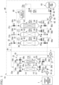
- a first embodiment of the carbon dioxide recovery facility will be described with reference to FIGS. 1 to 8 .
- the carbon dioxide recovery facility of this embodiment is a facility that recovers carbon dioxide in an exhaust gas from an exhaust gas generation source 1.
- the exhaust gas generation source 1 may be, for example, an incinerator, a boiler, a gas turbine, and the like.
- the composition of the exhaust gas from the exhaust gas generation source 1 is, for example, as follows. N 2 : 75.9 vol%, O 2 : 9.6 vol%, CO 2 : 5.4 vol%, H 2 O: 9.2 vol%
- the carbon dioxide recovery facility includes a pretreatment device 10 and a carbon dioxide recovery device 40.
- the pretreatment device 10 is a device for removing components from the exhaust gas that inhibit the carbon dioxide recovery in the carbon dioxide recovery device 40.
- the carbon dioxide recovery device 40 is a device that mainly recovers carbon dioxide in the exhaust gas from the pretreatment device 10.
- the pretreatment device 10 includes two dehumidification towers 11.
- Each of the two dehumidification towers 11 includes a container 12 and a moisture adsorbing material 15 filled in the container 12.
- the moisture adsorbing material 15 is made of a moisture adsorbent capable of adsorbing moisture. Examples of moisture adsorbents include activated alumina, silica gel, and zeolite.
- Each of the containers 12 of the two dehumidification towers 11 includes a first port 13 and a second port 14. The first port 13 is formed on one side of the container 12 based on the moisture adsorbing material 15, and the second port 14 is formed on the other side of the container 12 based on the moisture adsorbing material 15.
- one dehumidification tower 11 will be referred to as a first dehumidification tower 11a, and the remaining dehumidification tower 11 will be referred to as a second dehumidification tower 11b.
- the carbon dioxide recovery device 40 includes three adsorption towers 41.
- Each of the three adsorption towers 41 includes a container 42 and a carbon dioxide adsorbing material 45 filled in the container 42.
- the carbon dioxide adsorbing material 45 is formed of a carbon dioxide adsorbent capable of adsorbing carbon dioxide under high pressure and releasing carbon dioxide under low pressure.
- the carbon dioxide adsorbent in this embodiment is zeolite.
- Each of the containers 42 of the three adsorption towers 41 includes a first port 43 and a second port 44.
- the first port 43 is formed on one side of the container 42 based on the carbon dioxide adsorbing material 45
- the second port 44 is formed on the other side of the container 42 based on the carbon dioxide adsorbing material 45.
- one adsorption tower 41 will be referred to as a first adsorption tower 41a
- another adsorption tower 41 will be described as a second adsorption tower 41b
- the remaining adsorption tower 41 will be referred to as a third adsorption tower 41c.
- the carbon dioxide adsorbing material 45 is a porous structure having a plurality of through holes 46 penetrating in the same direction.
- the porous structure shown in FIG. 3 is sometimes called a honeycomb structure.
- Zeolite which is a type of carbon dioxide adsorbent can adsorb not only carbon dioxide but also water. Therefore, if moisture is contained in the exhaust gas, the ability of zeolite to adsorb carbon dioxide decreases. Therefore, in this embodiment, the pretreatment device 10 removes moisture in the exhaust gas.
- the pretreatment device 10 includes a blowing machine 16, a dehumidification vacuum pump 17, an exhaust gas line 20, a dry exhaust gas line 23, a moisture-rich gas line 27, an off-gas line 30, a first exhaust gas valve 35a, a second exhaust gas valve 35b, a dehumidification side first dry exhaust gas valve 36a, a dehumidification side second dry exhaust gas valve 36b, a first moisture-rich gas valve 37a, a second moisture-rich gas valve 37b, a dehumidification side first off-gas valve 38a, and a dehumidification side second off-gas valve 38b in addition to the first dehumidification tower 11a and the second dehumidification tower 11b described above.
- the exhaust gas line 20 includes a main exhaust gas line 21, a first exhaust gas line 22a, and a second exhaust gas line 22b.
- One end of the main exhaust gas line 21 is connected to the exhaust gas generation source 1.
- One end of the first exhaust gas line 22a and one end of the second exhaust gas line 22b are connected to the other end of the main exhaust gas line 21.
- the main exhaust gas line 21 is provided with the blowing machine 16.
- the other end of the first exhaust gas line 22a is connected to the first port 13 of the first dehumidification tower 11a, and the other end of the second exhaust gas line 22b is connected to the first port 13 of the second dehumidification tower 11b.
- the first exhaust gas line 22a is provided with the first exhaust gas valve 35a.
- the second exhaust gas line 22b is provided with the second exhaust gas valve 35b.
- the dry exhaust gas line 23 includes a dehumidification side first dry exhaust gas line 24a, a dehumidification side second dry exhaust gas line 24b, a main dry exhaust gas line 25, a recovery side first dry exhaust gas line 26a, a recovery side second dry exhaust gas line 26b, and a recovery side third dry exhaust gas line 26c.
- One end of the dehumidification side first dry exhaust gas line 24a is connected to the second port 14 of the first dehumidification tower 11a, and one end of the dehumidification side second dry exhaust gas line 24b is connected to the second port 14 of the second dehumidification tower 11b.
- the dehumidification side first dry exhaust gas line 24a is provided with the dehumidification side first dry exhaust gas valve 36a.
- the dehumidification side second dry exhaust gas line 24b is provided with the dehumidification side second dry exhaust gas valve 36b.
- One end of the main dry exhaust gas line 25 is connected to the other end of the dehumidification side first dry exhaust gas line 24a and the other end of the dehumidification side second dry exhaust gas line 24b.
- One end of the recovery side first dry exhaust gas line 26a, one end of the recovery side second dry exhaust gas line 26b, and one end of the recovery side third dry exhaust gas line 26c are connected to the other end of the main dry exhaust gas line 25.
- the recovery side first dry exhaust gas line 26a, the recovery side second dry exhaust gas line 26b, and the recovery side third dry exhaust gas line 26c are lines branched from the main dry exhaust gas line 25.
- the other end of the recovery side first dry exhaust gas line 26a is connected to the first port 43 of the first adsorption tower 41a.
- the other end of the recovery side second dry exhaust gas line 26b is connected to the first port 43 of the second adsorption tower 41b.
- the other end of the recovery side third dry exhaust gas line 26c is connected to the first port 43 of the third adsorption tower 41c.
- the moisture-rich gas line 27 includes a first moisture-rich gas line 28a, a second moisture-rich gas line 28b, and a main moisture-rich gas line 29.
- One end of the first moisture-rich gas line 28a is connected to a position on the side of the first dehumidification tower 11a rather than the first exhaust gas valve 35a in the first exhaust gas line 22a.
- One end of the second moisture-rich gas line 28b is connected to a position on the side of the second dehumidification tower 11b rather than the second exhaust gas valve 35b in the second exhaust gas line 22b.
- the first moisture-rich gas line 28a is provided with the first moisture-rich gas valve 37a
- the second moisture-rich gas line 28b is provided with the second moisture-rich gas valve 37b.
- One end of the main moisture-rich gas line 29 is connected to the other end of the first moisture-rich gas line 28a and the other end of the second moisture-rich gas line 28b.
- a suction port of the dehumidification vacuum pump 17 is connected to the other end of the main moisture-rich gas line 29.
- the off-gas line 30 includes a recovery side first off-gas line 31a, a recovery side second off-gas line 31b, a recovery side third off-gas line 31c, a main off-gas line 32, a dehumidification side first off-gas line 33a, and a dehumidification side second off-gas line 33b.
- One end of the recovery side first off-gas line 31a is connected to the second port 44 of the first adsorption tower 41a.
- One end of the recovery side second off-gas line 31b is connected to the second port 44 of the second adsorption tower 41b.
- One end of the recovery side third off-gas line 31c is connected to the second port 44 of the third adsorption tower 41c.
- the other end of the recovery side first off-gas line 31a, the other end of the recovery side second off-gas line 31b, and the other end of the recovery side third off-gas line 31c are connected to a one end side part of the main off-gas line 32.
- One end of the dehumidification side first off-gas line 33a and one end of the dehumidification side second off-gas line 33b are connected to the other end of the main off-gas line 32.
- the other end of the dehumidification side first off-gas line 33a is connected to the second port 14 of the first dehumidification tower 11a.
- the other end of the dehumidification side second off-gas line 33b is connected to the second port 14 of the second dehumidification tower 11b.
- the dehumidification side first off-gas line 33a is provided with the dehumidification side first off-gas valve 38a.
- the dehumidification side second off-gas line 33b is provided with the dehumidification side second off-gas valve 38b.
- the carbon dioxide recovery device 40 includes the blowing machine 16, the dry exhaust gas line 23, a suction machine 50, a recovery side first dry exhaust gas valve 56a, a recovery side second dry exhaust gas valve 56b, a recovery side third dry exhaust gas valve 56c, a first suction valve 57a, a second suction valve 57b, a third suction valve 57c, a recovery side first off-gas valve 58a, a recovery side second off-gas valve 58b, a recovery side third off-gas valve 58c, a recovery gas valve 60, a non-recovery gas valve 61, a recovery gas tank 63, a suction line 65, the off-gas line 30, a discharge line 68, a carbon dioxide recovery line 70, a non-recovery gas line 71, and a control device 80 in addition to the first adsorption tower 41a, the second adsorption tower 41b, and the third adsorption tower 41c described above.
- the blowing machine 16 In the components of the carbon dioxide recovery device 40, the blowing machine 16, the dry exhaust gas line 23, and the off-gas line 30 are components of the carbon dioxide recovery device 40 and are also components of the pretreatment device 10.
- the recovery side first dry exhaust gas valve 56a is provided in the recovery side first dry exhaust gas line 26a described above.
- the recovery side second dry exhaust gas valve 56b is provided in the recovery side second dry exhaust gas line 26b described above.
- the recovery side third dry exhaust gas valve 56c is provided in the recovery side third dry exhaust gas line 26c described above.
- the recovery side first off-gas valve 58a is provided in the recovery side first off-gas line 31a described above.
- the recovery side second off-gas valve 58b is provided in the recovery side second off-gas line 31b described above.
- the recovery side third off-gas valve 58c is provided in the recovery side third off-gas line 31c described above.
- the suction line 65 includes a first suction line 66a, a second suction line 66b, a third suction line 66c, and a main suction line 67.
- One end of the first suction line 66a is connected to a position on the side of the first adsorption tower 41a rather than the recovery side first dry exhaust gas valve 56a in the recovery side first dry exhaust gas line 26a.
- the first suction line 66a is provided with the first suction valve 57a.
- One end of the second suction line 66b is connected to a position on the side of the second adsorption tower 41b rather than the recovery side second dry exhaust gas valve 56b in the recovery side second dry exhaust gas line 26b.
- the second suction line 66b is provided with the second suction valve 57b.
- One end of the third suction line 66c is connected to a position on the side of the third adsorption tower 41c rather than the recovery side third dry exhaust gas valve 56c in the recovery side third dry exhaust gas line 26c.
- the third suction line 66c is provided with the third suction valve 57c.
- the other end of the first suction line 66a, the other end of the second suction line 66b, and the other end of the third suction line 66c are connected to one end side part of the main suction line 67.
- the other end of the main suction line 67 is connected to a suction port of the suction machine 50.
- the suction machine 50 is, for example, a vacuum pump.
- One end of the discharge line 68 is connected to a discharge port of the suction machine 50.
- One end of the carbon dioxide recovery line 70 and one end of the non-recovery gas line 71 are connected to the other end of the discharge line 68.
- the non-recovery gas line 71 includes a non-recovery gas discharge line 72a having an open end.
- the non-recovery gas valve 61 includes a discharge valve 62a provided in the non-recovery gas discharge line 72a.
- the other end of the carbon dioxide recovery line 70 is connected to the recovery gas tank 63.
- the carbon dioxide recovery line 70 is provided with the recovery gas valve 60.
- the control device 80 includes a pressure gauge 81 which is provided for each of the three adsorption towers 41 and a valve controller 82 which controls the operation of the recovery gas valve 60 and the discharge valve 62a based on the pressure detected by the pressure gauge 81.
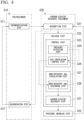
- the carbon dioxide recovery facility executes a pretreatment S10 and a carbon dioxide recovery treatment S20.
- the pretreatment S10 is executed by the pretreatment device 10
- the carbon dioxide recovery treatment S20 is executed by the carbon dioxide recovery device 40.
- a dehumidification step S11 and a regeneration step S12 are executed. It is assumed that the moisture adsorption amount of the moisture adsorbing material 15 in the first dehumidification tower 11a is extremely small and the moisture adsorption amount of the moisture adsorbing material 15 in the second dehumidification tower 11b is large. In this case, as shown in FIG.
- the first exhaust gas valve 35a is in an open state
- the second exhaust gas valve 35b is in a closed state
- the dehumidification side first dry exhaust gas valve 36a is in an open state
- the dehumidification side second dry exhaust gas valve 36b is in a closed state
- the first moisture-rich gas valve 37a is in a closed state
- the second moisture-rich gas valve 37b is in an open state
- the dehumidification side first off-gas valve 38a is in a closed state
- the dehumidification side second off-gas valve 38b is in an open state.
- the exhaust gas from the exhaust gas generation source 1 flows into the first dehumidification tower 11a through the main exhaust gas line 21, the blowing machine 16, the first exhaust gas line 22a, and the first exhaust gas valve 35a.
- the exhaust gas having flowed into the first dehumidification tower 11a passes through the moisture adsorbing material 15 in the first dehumidification tower 11a, most of the moisture contained in the exhaust gas is adsorbed by the moisture adsorbing material 15 and the remainder is exhausted from the first dehumidification tower 11a as a dry exhaust gas. That is, the exhaust gas is dehumidified in the first dehumidification tower 11a.
- the dry exhaust gas is sent to the carbon dioxide recovery device 40 through the dehumidification side first dry exhaust gas line 24a, the dehumidification side first dry exhaust gas valve 36a, and the main dry exhaust gas line 25 (dehumidification step S11).
- the off-gas with low moisture content flows from the carbon dioxide recovery device 40 into the second dehumidification tower 11b through the main off-gas line 32, the dehumidification side second off-gas line 33b, and the dehumidification side second off-gas valve 38b.
- the off-gas having flowed into the second dehumidification tower 11b passes through the moisture adsorbing material 15 in the second dehumidification tower 11b, the moisture is released from the moisture adsorbing material 15 and the gas is exhausted from the second dehumidification tower 11b together with the moisture. That is, the moisture adsorbing material 15 is regenerated in the second dehumidification tower 11b.
- the off-gas containing the moisture is discharged to the outside as a moisture-rich gas through the second moisture-rich gas line 28b, the second moisture-rich gas valve 37b, the main moisture-rich gas line 29, and the dehumidification vacuum pump 17 (regeneration step S12). Furthermore, the moisture-rich gas may be discharged into the atmosphere or tank.
- the moisture adsorption amount of the moisture adsorbing material 15 in the first dehumidification tower 11a increases.
- the regeneration step S12 is executed in the second dehumidification tower 11b, the moisture adsorption amount of the moisture adsorbing material 15 in the second dehumidification tower 11b becomes extremely small.
- the first exhaust gas valve 35a is in a closed state
- the second exhaust gas valve 35b is in an open state
- the dehumidification side first dry exhaust gas valve 36a is in a closed state
- the dehumidification side second dry exhaust gas valve 36b is in an open state
- the first moisture-rich gas valve 37a is in an open state
- the second moisture-rich gas valve 37b is in a closed state
- the dehumidification side first off-gas valve 38a is in an open state
- the dehumidification side second off-gas valve 38b is in a closed state.
- the exhaust gas from the exhaust gas generation source 1 flows into the second dehumidification tower 11b through the main exhaust gas line 21, the blowing machine 16, the second exhaust gas line 22b, and the second exhaust gas valve 35b.
- the exhaust gas having flowed into the second dehumidification tower 11b passes through the moisture adsorbing material 15 in the second dehumidification tower 11b, most of the moisture contained in the exhaust gas is adsorbed by the moisture adsorbing material 15, and the remainder is exhausted from the second dehumidification tower 11b as a dry exhaust gas. That is, the exhaust gas is dehumidified in the second dehumidification tower 11b.
- the dry exhaust gas is sent to the carbon dioxide recovery device 40 through the dehumidification side second dry exhaust gas line 24b, the dehumidification side second dry exhaust gas valve 36b, and the main dry exhaust gas line 25 (dehumidification step S11).
- the off-gas with low moisture content flows from the carbon dioxide recovery device 40 into the first dehumidification tower 11a through the main off-gas line 32, the dehumidification side first off-gas line 33a, and the dehumidification side first off-gas valve 38a.
- the off-gas having flowed into the first dehumidification tower 11a passes through the moisture adsorbing material 15 in the first dehumidification tower 11a, the moisture is released from the moisture adsorbing material 15 and the gas is exhausted from the first dehumidification tower 11a together with moisture. That is, the moisture adsorbing material 15 is regenerated in the first dehumidification tower 11a.
- the off-gas containing the moisture is discharged to the outside as a moisture-rich gas through the first moisture-rich gas line 28a, the first moisture-rich gas valve 37a, the main moisture-rich gas line 29, and the dehumidification vacuum pump 17 (regeneration step S12).
- the regeneration step S12 is executed after the dehumidification step S11, and the dehumidification step S11 is executed after the regeneration step S12. Further, when the dehumidification step S11 is executed in the first dehumidification tower 11a, the regeneration step S12 is executed in the second dehumidification tower 11b. Further, when the dehumidification step S11 is executed in the second dehumidification tower 11b, the regeneration step S12 is executed in the first dehumidification tower 11a. Therefore, in this embodiment, the moisture in the exhaust gas can be continuously removed.
- an adsorption step S21, a release step S22, and a pressure increase step S32 are executed. It is assumed that the carbon dioxide adsorption amount of the carbon dioxide adsorbing material 45 in the first adsorption tower 41a and the carbon dioxide adsorbing material 45 in the second adsorption tower 41b is extremely small and the carbon dioxide adsorption amount of the carbon dioxide adsorbing material 45 in the third adsorption tower 41c is large. Further, it is assumed that the pressure in the first adsorption tower 41a is a negative pressure and the pressure in the second adsorption tower 41b is an approximately atmospheric pressure. In this case, as shown in FIG.
- the recovery side first dry exhaust gas valve 56a is in a closed state
- the recovery side second dry exhaust gas valve 56b is in an open state
- the recovery side third dry exhaust gas valve 56c is in a closed state
- the first suction valve 57a is in a closed state
- the second suction valve 57b is in a closed state
- the third suction valve 57c is in an open state
- the recovery side first off-gas valve 58a is in a half opened state
- the recovery side second off-gas valve 58b is in an open state
- the recovery side third off-gas valve 58c is in a closed state.
- the dry exhaust gas from the pretreatment device 10 flows into the second adsorption tower 41b through the main dry exhaust gas line 25, the recovery side second dry exhaust gas line 26b, and the recovery side second dry exhaust gas valve 56b.
- the dry exhaust gas having flowed into the second adsorption tower 41b passes through the carbon dioxide adsorbing material 45 in the second adsorption tower 41b, most of the carbon dioxide contained in the dry exhaust gas is adsorbed by the carbon dioxide adsorbing material 45 and the remainder is exhausted from the second adsorption tower 41b as an off-gas. That is, the carbon dioxide adsorbing material 45 in the second adsorption tower 41b adsorbs the carbon dioxide in the dry exhaust gas (adsorption step S21).
- the carbon dioxide adsorbing material 45 is a porous structure. Therefore, since the gas flow in the second adsorption tower 41b does not cause fluidization, it is possible to prevent the carbon dioxide adsorbing material 45 from flowing out of the adsorption tower 41.
- a part of the off-gas exhausted from the second adsorption tower 41b is sent to the dehumidification tower 11 in the regeneration step S12 through the recovery side second off-gas line 31b, the recovery side second off-gas valve 58b, and the main off-gas line 32.
- the remaining part of the off-gas exhausted from the second adsorption tower 41b is sent to the first adsorption tower 41a through the recovery side second off-gas line 31b, the recovery side second off-gas valve 58b, the main off-gas line 32, the recovery side first off-gas line 31a, and the recovery side first off-gas valve 58a.
- the pressure in the first adsorption tower 41a is increased from a negative pressure to an approximately atmospheric pressure (pressure increase step S32).
- the inside of the third adsorption tower 41c is vacuum-suctioned by the suction machine 50 through the third suction line 66c, the third suction valve 57c, and the main suction line 67.
- the carbon dioxide adsorbed by the carbon dioxide adsorbing material 45 in the third adsorption tower 41c is released and discharged from the suction machine 50 (release step S22). Furthermore, the release step S22 will be described in detail later.
- the carbon dioxide adsorption amount of the carbon dioxide adsorbing material 45 in the second adsorption tower 41b increases.
- the release step S22 is executed in the third adsorption tower 41c
- the carbon dioxide adsorption amount of the carbon dioxide adsorbing material 45 in the third adsorption tower 41c is extremely small and the pressure in the third adsorption tower 41c is a negative pressure.
- the pressure increase step S32 is executed in the first adsorption tower 41a, the pressure in the first adsorption tower 41a becomes an approximately atmospheric pressure.
- the carbon dioxide adsorption amount of the carbon dioxide adsorbing material 45 in the first adsorption tower 41a is extremely small.
- the carbon dioxide adsorption amount of the carbon dioxide adsorbing material 45 in the first adsorption tower 41a and the carbon dioxide adsorbing material 45 in the third adsorption tower 41c is extremely small and the carbon dioxide adsorption amount of the carbon dioxide adsorbing material 45 in the second adsorption tower 41b is large.
- the pressure in the first adsorption tower 41a is an approximately atmospheric pressure and the pressure in the third adsorption tower 41c is a negative pressure. In this case, as shown in FIG.
- the recovery side first dry exhaust gas valve 56a is in an open state
- the recovery side second dry exhaust gas valve 56b is in a closed state
- the recovery side third dry exhaust gas valve 56c is in a closed state
- the first suction valve 57a is in a closed state
- the second suction valve 57b is in an open state
- the third suction valve 57c is in a closed state
- the recovery side first off-gas valve 58a is in an open state
- the recovery side second off-gas valve 58b is in a closed state
- the recovery side third off-gas valve 58c is in a half opened state.
- the dry exhaust gas from the pretreatment device 10 flows into the first adsorption tower 41a through the main dry exhaust gas line 25, the recovery side first dry exhaust gas line 26a, and the recovery side first dry exhaust gas valve 56a.
- the dry exhaust gas having flowed into the first adsorption tower 41a passes through the carbon dioxide adsorbing material 45 in the first adsorption tower 41a, most of the carbon dioxide contained in the dry exhaust gas is adsorbed by the carbon dioxide adsorbing material 45 and the remainder is exhausted from the first adsorption tower 41a as an off-gas. That is, the first adsorption tower 41a adsorbs the carbon dioxide in the dry exhaust gas (adsorption step S21).
- a part of the off-gas exhausted from the first adsorption tower 41a is sent to the dehumidification tower 11 in the regeneration step S12 through the recovery side first off-gas line 31a, the recovery side first off-gas valve 58a, and the main off-gas line 32.
- the remaining part of the off-gas exhausted from the first adsorption tower 41a is sent to the third adsorption tower 41c through the recovery side first off-gas line 31a, the recovery side first off-gas valve 58a, the main off-gas line 32, the recovery side third off-gas line 31c, and the recovery side third off-gas valve 58c.
- the pressure in the third adsorption tower 41c is increased from a negative pressure to an approximately atmospheric pressure (pressure increase step S32).
- the inside of the second adsorption tower 41b is vacuum-suctioned by the suction machine 50 through the second suction line 66b, the second suction valve 57b, and the main suction line 67.
- the carbon dioxide adsorbed by the carbon dioxide adsorbing material 45 in the second adsorption tower 41b is released and discharged from the suction machine 50 (release step S22).
- the release step S22 is executed after the adsorption step S21
- the pressure increase step S32 is executed after the release step S22
- the adsorption step S21 is executed after the pressure increase step S32.
- the release step S22 is executed in the third adsorption tower 41c
- the pressure increase step S32 is executed in the first adsorption tower 41a.
- the release step S22 is executed in the second adsorption tower 41b
- the pressure increase step S32 is executed in the third adsorption tower 41c
- the adsorption step S21 is executed in the first adsorption tower 41a. Therefore, in this embodiment, the carbon dioxide in the dry exhaust gas can be continuously recovered.
- the pressure increase step S32 is executed after the release step S22.
- the vacuum degree in the adsorption tower 41 after the release step S22 is high. Therefore, when the adsorption step S21 is executed while the vacuum degree is kept high, the exhaust gas passes through the carbon dioxide adsorbing material 45 even when the exhaust gas is sent to the adsorption tower 41, and hence the carbon dioxide adsorption efficiency decreases. Therefore, in this embodiment, the pressure increase step S32 is executed after the release step S22 and then the adsorption step S21 is executed.
- zeolite used as the carbon dioxide adsorbent in this embodiment is a general term for crystalline aluminosilicate.
- the chemical formula of zeolite can be expressed as below. Me 2 /xO ⁇ Al 2 O 3 ⁇ mSiO 2 ⁇ nH 2 O Me: X-valent cation
- the crystal structure of zeolite is not uniform, and there are, for example, A type, X type, Y type, beta type, and the like.
- Na ions, Li ions, Ca ions, and the like are used.
- zeolite with an X-type crystal structure and using Na ions as Me is referred to as NaX type.
- zeolite having an X-type crystal structure and using Li ions as Me is referred to as LiX type
- CaX type zeolite having an X-type crystal structure and using Ca ions as Me.
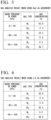
- FIGS. 5 to 7 show an analysis result when NaX type zeolite was used.
- FIG. 6 shows an analysis result when LiaX type zeolite was used.
- FIG. 7 shows an analysis result when CaX type zeolite was used.
- the vacuum degree in the adsorption tower 41 when the vacuum degree in the adsorption tower 41 is low, in other words, when the gauge pressure in the adsorption tower 41 is high regardless of the type of zeolite, the nitrogen concentration in the suction gas is high and the carbon dioxide concentration in the suction gas is low.
- the vacuum degree in the adsorption tower 41 is increased, in other words, the gauge pressure in the adsorption tower 41 is decreased, the nitrogen concentration in the suction gas gradually decreases and the carbon dioxide concentration in the suction gas gradually increases.
- the gauge pressure in the adsorption tower 41 is -80 kPa
- the carbon dioxide concentration in the suction gas is approximately 80% regardless of the type of zeolite used.
- the inventor could recover high-concentration carbon dioxide by not recovering the suction gas in a tank or the like when the pressure in the adsorption tower 41 is a low vacuum based on a predetermined recovery pressure Pc and by recovering the suction gas in a tank or the like when the pressure in the adsorption tower 41 is a high vacuum based on the recovery pressure Pc. Furthermore, in this embodiment and each of the following embodiments, the recovery pressure Pc is set to -80 kPaG.
- the release step S22 described above includes a control step S23, a non-recovery gas circulation step S27, and a carbon dioxide recovery step S31.
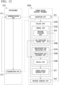
- the control step S23 includes a pressure detection step S24 of detecting the pressure in the adsorption tower 41 in the release step S22 by the pressure gauge 81 and a gas circulation control step S26 of controlling the opening and closing of the recovery gas valve 60 and the discharge valve 62a by the valve controller 82 based on the pressure detected by the pressure gauge 81.
- the non-recovery gas circulation step S27 includes a non-recovery gas discharge step S28 of discharging the suction gas from the suction machine 50 to the atmosphere.
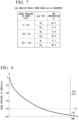
- the gauge pressure in the adsorption tower 41 gradually decreases with time, in other words, the vacuum degree in the adsorption tower 41 gradually increases as shown in FIG. 8 .
- the valve controller 82 issues a close command to the recovery gas valve 60 and issues an open command to the discharge valve 62a (gas circulation control step S26).
- the recovery gas valve 60 is in a closed state
- the discharge valve 62a is in an open state
- the suction gas from the suction machine 50 is discharged to the atmosphere through the non-recovery gas discharge line 72a and the discharge valve 62a (non-recovery gas discharge step S28).
- the valve controller 82 issues an open command to the recovery gas valve 60 and issues a close command to the discharge valve 62a (gas circulation control step S26).
- the recovery gas valve 60 is in an open state
- the discharge valve 62a is in a closed state
- the suction gas from the suction machine 50 is recovered by the recovery gas tank 63 through the carbon dioxide recovery line 70 and the recovery gas valve 60 (carbon dioxide recovery step S31).
- the suction gas from the suction machine 50 is guided to the recovery gas tank 63.
- the vacuum degree in the adsorption tower 41 is a higher vacuum than the recovery pressure Pc (-80 kPaG)
- the concentration of carbon dioxide in the suction gas is approximately 80% or more. Therefore, in this embodiment, high-concentration carbon dioxide can be recovered.
- FIGS. 9 and 10 A second embodiment of the carbon dioxide recovery facility will be described with reference to FIGS. 9 and 10 .
- the carbon dioxide recovery facility of this embodiment includes the pretreatment device 10 and a carbon dioxide recovery device 40a as in the carbon dioxide recovery facility of the first embodiment.
- the pretreatment device 10 of this embodiment is the same as the pretreatment device 10 of the first embodiment.
- the carbon dioxide recovery device 40a of this embodiment is different from the carbon dioxide recovery device 40 of the first embodiment.
- the non-recovery gas line 71 includes the non-recovery gas discharge line 72a and the non-recovery gas valve 61 includes the discharge valve 62a.
- the non-recovery gas line 71a includes a recycle line 72b and the non-recovery gas valve 61a includes a recycle valve 62b. Therefore, the operation of the valve controller 82a of the control device 80a is also different from the operation of the valve controller 82 of the control device 80 of the first embodiment.
- One end of the recycle line 72b is connected to the other end of the discharge line 68, and the other end of the recycle line 72b is connected to the main dry exhaust gas line 25.
- the recycle line 72b is provided with the recycle valve 62b described above.
- the recycle line 72b is provided instead of the non-recovery gas discharge line 72a of the first embodiment, and the recycle valve 62b is provided instead of the discharge valve 62a of the first embodiment.
- the carbon dioxide recovery facility of this embodiment also executes the pretreatment S10 and a carbon dioxide recovery treatment S20a as in the carbon dioxide recovery facility of the first embodiment.
- the pretreatment S10 is the same as the pretreatment S10 of the first embodiment.
- the carbon dioxide recovery treatment S20a is different from the carbon dioxide recovery treatment S20 of the first embodiment.
- the carbon dioxide recovery treatment S20a of this embodiment also includes the adsorption step S21, a release step S22a, and the pressure increase step S32 as in the carbon dioxide recovery treatment S20 of the first embodiment.
- the adsorption step S21 of this embodiment is the same as the adsorption step S21 of the first embodiment.
- the pressure increase step S32 of this embodiment is the same as the pressure increase step S32 of the first embodiment.
- the release step S22a of this embodiment also includes a control step S23a, a non-recovery gas circulation step S27a, and the carbon dioxide recovery step S31 as in the release step S22 of the first embodiment.
- the control step S23a of this embodiment also includes the pressure detection step S24 and a gas circulation control step S26a as in the control step S23 of the first embodiment.
- the recycle valve 62b is provided instead of the discharge valve 62a of the first embodiment as described above, the control contents of the gas circulation control step S26a by the valve controller 82a are different from those of the gas circulation control step S26 of the first embodiment.
- the non-recovery gas circulation step S27a includes a recycle step S29 instead of the non-recovery gas discharge step S28 of the non-recovery gas circulation step S27 of the first embodiment.
- the gauge pressure in the adsorption tower 41 gradually decreases, in other words, the vacuum degree in the adsorption tower 41 gradually increases with time as described above with reference to FIG. 8 .
- the valve controller 82a issues a close command to the recovery gas valve 60 and issues an open command to the recycle valve 62b (gas circulation control step S26a).
- the recovery gas valve 60 is in a closed state
- the recycle valve 62b is in an open state
- the suction gas from the suction machine 50 flows into the adsorption tower 41 which is the execution target of the adsorption step S21 through the recycle line 72b, the recycle valve 62b, and the main dry exhaust gas line 25 (recycle step S29).
- the valve controller 82a issues an open command to the recovery gas valve 60 and issues a close command to the discharge valve 62a (gas circulation control step S26a).
- the recovery gas valve 60 is in an open state
- the discharge valve 62a is in a closed state
- the suction gas from the suction machine 50 is recovered in the recovery gas tank 63 through the carbon dioxide recovery line 70 and the recovery gas valve 60 (carbon dioxide recovery step S31).
- the suction gas from the suction machine 50 is guided to the recovery gas tank 63.
- high-concentration carbon dioxide can be recovered. Therefore, even in this embodiment, as in the first embodiment, it is possible to suppress an increase in installation area for the facility and facility cost. Further, even in this embodiment, it is possible to shorten the time required to recover carbon dioxide from the exhaust gas.
- the pressure in the adsorption tower 41 which is the execution target of the release step S22a is a lower vacuum than the recovery pressure Pc, the suction gas from the suction machine 50 is not discharged to the atmosphere and is flowed into the adsorption tower 41 which is the execution target of the adsorption step S21. Therefore, in this embodiment, the carbon dioxide discharge amount can be reduced compared to the first embodiment.
- a third embodiment of the carbon dioxide recovery facility will be described with reference to FIGS. 11 to 13 .
- the carbon dioxide recovery facility of this embodiment includes the pretreatment device 10 and a carbon dioxide recovery device 40b as in the carbon dioxide recovery facility of each of the above-described embodiments.
- the pretreatment device 10 of this embodiment is the same as the pretreatment device 10 of the first embodiment.
- the carbon dioxide recovery device 40b of this embodiment is different from the carbon dioxide recovery device 40 of the first embodiment.
- the non-recovery gas line 71 includes the non-recovery gas discharge line 72a, and the non-recovery gas valve 61 includes the discharge valve 62a.
- the non-recovery gas line 71b includes the recycle line 72b in addition to the non-recovery gas discharge line 72a.
- the non-recovery gas valve 61b of this embodiment includes the recycle valve 62b in addition to the discharge valve 62a. Therefore, the operation of the valve controller 82b of the control device 80b is also different from the operation of the valve controller 82 of the control device 80 of the first embodiment.
- one end of the recycle line 72b is connected to the other end of the discharge line 68, and the other end of the recycle line 72b is connected to the main dry exhaust gas line 25.
- the recycle line 72b is provided with the recycle valve 62b described above.
- the carbon dioxide recovery facility of this embodiment also executes the pretreatment S10 and a carbon dioxide recovery treatment S20b as in the carbon dioxide recovery facility of the first embodiment.
- the pretreatment S10 is the same as the pretreatment S10 of the first embodiment.
- the carbon dioxide recovery treatment S20b is different from the carbon dioxide recovery treatment S20 of the first embodiment.
- the carbon dioxide recovery treatment S20b of this embodiment also includes the adsorption step S21, a release step S22b, and the pressure increase step S32 as in the carbon dioxide recovery treatment S20 of the first embodiment.
- the adsorption step S21 of this embodiment is the same as the adsorption step S21 of the first embodiment.
- the pressure increase step S32 of this embodiment is the same as the pressure increase step S32 of the first embodiment.
- the release step S22b of this embodiment also includes a control step S23b, a non-recovery gas circulation step S27b, and the carbon dioxide recovery step S31 as in the release step S22 of the first embodiment.
- the control step S23b of this embodiment also includes the pressure detection step S24 and a gas circulation control step S26b as in the control step S23 of the first embodiment.
- the recovery gas valve 60 includes the recycle valve 62b in addition to the discharge valve 62a as described above, the control contents of the gas circulation control step S26b by the valve controller 82b are different from those of the gas circulation control step S26 of the first embodiment.
- the non-recovery gas circulation step S27b of this embodiment includes a recycle step S29b in addition to a non-recovery gas discharge step S28b.
- the gauge pressure in the adsorption tower 41 gradually decreases, in other words, the vacuum degree in the adsorption tower 41 gradually increases with time as shown in FIG. 13 .
- the valve controller 82b issues an open command to the discharge valve 62a and issues a close command to the recycle valve 62b and the recovery gas valve 60 (gas circulation control step S26b).
- the recycle valve 62b and the recovery gas valve 60 are in a closed state, the discharge valve 62a is in an open state, and the suction gas from the suction machine 50 is discharged to the atmosphere through the non-recovery gas discharge line 72a and the discharge valve 62a (non-recovery gas discharge step S28b).
- the recycle pressure Pr is a pressure between the recovery pressure Pc and the atmospheric pressure, and is closer to the atmospheric pressure than the recovery pressure Pc. Further, the recycle pressure Pr is a pressure at which the carbon dioxide concentration in the suction gas from the suction machine 50 becomes lower than the carbon dioxide concentration in the dry exhaust gas when the vacuum is lower than the recycle pressure Pr.
- the recycle pressure Pr is, for example, -10 kPaG.
- valve controller 82b issues an open command to the recycle valve 62b and issues a close command to the discharge valve 62a and the recovery gas valve 60 (gas circulation control step S26b).
- the discharge valve 62a and the recovery gas valve 60 are in a closed stat, the recycle valve 62b is in an open state, and the suction gas from the suction machine 50 flows into the adsorption tower 41 which is the execution target of the adsorption step S21 through the recycle line 72b, the recycle valve 62b, and the main dry exhaust gas line 25 (recycle step S29b).
- the valve controller 82b issues an open command to the recovery gas valve 60 and issues a close command to the discharge valve 62a and the recycle valve 62b (gas circulation control step S26b).
- the recovery gas valve 60 is in an open state
- the discharge valve 62a and the recycle valve 62b are in a closed state
- the suction gas from the suction machine 50 is recovered in the recovery gas tank 63 through the carbon dioxide recovery line 70 and the recovery gas valve 60 (carbon dioxide recovery step S31).
- the pressure in the adsorption tower 41 which is the execution target of the release step S22b is a higher vacuum than the recycle pressure Pr and a lower vacuum than the recovery pressure Pc, the suction gas from the suction machine 50 is not discharged to the atmosphere and is flowed into the adsorption tower 41 which is the execution target of the adsorption step S21. Therefore, in this embodiment, the carbon dioxide discharge amount can be reduced compared to the first embodiment.
- the pressure in the adsorption tower 41 which is the execution target of the release step S22b is a lower vacuum than the recycle pressure Pr
- the carbon dioxide concentration in the suction gas from the suction machine 50 is lower than the carbon dioxide concentration in the dry exhaust gas.
- a gas having a lower carbon dioxide concentration than the dry exhaust gas is flowed into the adsorption tower 41 which is the execution target of the adsorption step S21 together with the dry exhaust gas.
- the carbon dioxide adsorption efficiency by the carbon dioxide adsorbing material 45 in the adsorption tower 41 which is the execution target of the adsorption step S21 decreases.
- the pressure in the adsorption tower 41 which is the execution target of the release step S22b is a lower vacuum than the recycle pressure Pr, the suction gas from the suction machine 50 is discharged to the atmosphere.
- a fourth embodiment of the carbon dioxide recovery facility will be described with reference to FIGS. 14 to 18 .
- the carbon dioxide recovery facility of this embodiment includes the pretreatment device 10 and a carbon dioxide recovery device 40c as in the carbon dioxide recovery facility of each of the above-described embodiments.
- the pretreatment device 10 of this embodiment is the same as the pretreatment device 10 of the first embodiment.
- the carbon dioxide recovery device 40c of this embodiment is a modified example of the carbon dioxide recovery device 40b of the third embodiment.
- a suction machine 50x of this embodiment is a suction machine capable of changing a suction force.
- a control device 80c of this embodiment includes a suction machine controller 83 which controls the operation of the suction machine 50 in addition to the valve controller 82b and the pressure gauge 81 of the control device 80b of the third embodiment.
- the suction machine 50x capable of changing the suction force
- a suction machine xa shown in FIG. 15 or a suction machine 50xb shown in FIG. 16 there is a suction machine xa shown in FIG. 15 or a suction machine 50xb shown in FIG. 16 .
- the suction machine 50xa shown in FIG. 15 includes a suction machine body 51, a motor 52 which drives the suction machine body 51, and an inverter 53 which controls the rotation speed of the motor 52.
- the inverter 53 changes the rotation speed of the motor 52 to change the suction force of the suction machine body 51.
- first suction machine body 51a includes a first suction machine body 51a, a first motor 52a which drives the first suction machine body 51a, a first switch 54a which controls the driving of the first motor 52a, a second suction machine body 51b, a second motor 52b which drives the second suction machine body 51b, and a second switch 54b which controls the driving of the second motor 52b. Therefore, a state in which the first suction machine body 51a is operated can be switched to a state in which the second suction machine body 51b is operated by controlling the first switch 54a and the second switch 54b.
- the suction force of the second suction machine body 51b is higher than the suction force of the first suction machine body 51a.
- the suction machine 50xb a state in which the first suction machine body 51a is operated is switched to a state in which the second suction machine body 51b is operated so that the suction force of the suction machine 50xb changes.
- the first suction machine body 51a and the second suction machine body 51b may be, for example, a vacuum pump. Furthermore, since the suction force of the first suction machine body 51a is lower than the suction force of the second suction machine body 51b, the first suction machine body 51a may be a blower.
- the non-recovery gas line 71b of this embodiment is the same as the non-recovery gas line 71b of the third embodiment. That is, the non-recovery gas line 71b of this embodiment also includes the non-recovery gas discharge line 72a and the recycle line 72b. Further, the non-recovery gas valve 61b of this embodiment is the same as the non-recovery gas valve 61b of the third embodiment. That is, the non-recovery gas valve 61b of this embodiment also includes the discharge valve 62a and the recycle valve 62b.
- the carbon dioxide recovery treatment S20c of this embodiment also includes the adsorption step S21, a release step S22c, and the pressure increase step S32 as in the carbon dioxide recovery treatment S20b of the third embodiment.
- the adsorption step S21 of this embodiment is the same as the adsorption step S21 of the third embodiment.
- the pressure increase step S32 of this embodiment is the same as the pressure increase step S32 of the third embodiment.
- the release step S22c of this embodiment also includes a control step S23c, the non-recovery gas circulation step S27b, and the carbon dioxide recovery step S31 as in the release step S22b of the third embodiment.
- the control step S23c of this embodiment also includes the pressure detection step S24 and the gas circulation control step S26b as in the control step S23b of the third embodiment. Further, the control step S23c of this embodiment includes a suction force control step S25. That is, the control step S23c of this embodiment includes the pressure detection step S24, the suction force control step S25, and the gas circulation control step S26b.
- the non-recovery gas circulation step S27b of this embodiment includes the non-recovery gas discharge step S28b and the recycle step S29b as in the non-recovery gas circulation step S27b of the third embodiment.
- the carbon dioxide recovery step S31 of this embodiment is the same as the carbon dioxide recovery step S31 of the third embodiment.
- the gauge pressure in the adsorption tower 41 gradually decreases, in other words, the vacuum degree in the adsorption tower 41 gradually increases with time as shown in FIG. 18 .
- the valve controller 82b issues an open command to the discharge valve 62a and issues a close command to the recycle valve 62b and the recovery gas valve 60 (gas circulation control step S26b).
- the recycle valve 62b and the recovery gas valve 60 are in a closed state, the discharge valve 62a is in an open state, and the suction gas from the suction machine 50 is discharged to the atmosphere through the non-recovery gas discharge line 72a and the discharge valve 62a (non-recovery gas discharge step S28b).
- valve controller 82b issues an open command to the recycle valve 62b and issues a close command to the discharge valve 62a and the recovery gas valve 60 (gas circulation control step S26b).
- the discharge valve 62a and the recovery gas valve 60 are in a closed state
- the recycle valve 62b is in an open state
- the suction gas from the suction machine 50 flows into the adsorption tower 41 which is the execution target of the adsorption step S21 through the recycle line 72b, the recycle valve 62b, and the main dry exhaust gas line 25 (recycle step S29b).
- the suction machine controller 83 instructs the suction machine 50x to increase the suction force (suction force control step S25). As a result, the suction force of the suction machine 50x increases, and as shown in FIG. 18 , the pressure in the adsorption tower 41 suddenly decreases.
- the suction force change pressure Ps described above is a pressure between the recovery pressure Pc and the atmospheric pressure, and is a pressure closer to the recovery pressure Pc than the atmospheric pressure or the same pressure as the recovery pressure Pc.
- the suction force change pressure Ps is, for example, -70 kPaG.
- the valve controller 82b issues an open command to the recovery gas valve 60 and issues a close command to the discharge valve 62a and the recycle valve 62b (gas circulation control step S26b).
- the recovery gas valve 60 is in an open state
- the discharge valve 62a and the recycle valve 62b are in a closed state
- the suction gas from the suction machine 50x is recovered in the recovery gas tank 63 through the carbon dioxide recovery line 70 and the recovery gas valve 60 (carbon dioxide recovery step S31).
- the suction force by the suction machine 50x is increased.
- the pressure in the adsorption tower 41 suddenly decreases after the pressure becomes the suction force change pressure Ps. Therefore, in this embodiment, the execution time of the carbon dioxide recovery step S31 can be shortened compared to the third embodiment.
- this embodiment is the modified example of the third embodiment, but the characteristic configuration of this embodiment may be applied to the first embodiment or the second embodiment. That is, the suction force of the suction machine 50x may be controlled by the suction machine controller 83 by using the suction machine 50x capable of changing the suction force as the suction machine of the first embodiment and the second embodiment.
- a fifth embodiment of the carbon dioxide recovery facility will be described with reference to FIGS. 19 to 21 .
- the carbon dioxide recovery facility of this embodiment includes the pretreatment device 10 and a carbon dioxide recovery device 40d as in the carbon dioxide recovery facility of each of the above-described embodiments.
- the pretreatment device 10 of this embodiment is the same as the pretreatment device 10 of the first embodiment.
- the carbon dioxide recovery device 40d of this embodiment is a modified example of the carbon dioxide recovery device 40b of the third embodiment.
- the suction machine 50x of this embodiment is also a suction machine capable of changing a suction force as in the suction machine 50x of the fourth embodiment.
- a control device 80d of this embodiment includes a suction machine controller 83d which controls the operation of the suction machine 50x in addition to the valve controller 82b of the control device 80b of the third embodiment.
- the control device 80d of this embodiment does not include the pressure gauge 81 of the control device 80b of the third embodiment.
- the control device 80d of this embodiment is a device in which the pressure gauge 81 is removed from the components of the control device 80c of the fourth embodiment.
- the non-recovery gas line 71b of this embodiment is the same as the non-recovery gas line 71b of the third embodiment and the fourth embodiment. That is, the non-recovery gas line 71b of this embodiment also includes the non-recovery gas discharge line 72a and the recycle line 72b. Further, the non-recovery gas valve 61b of this embodiment is the same as the non-recovery gas valve 61b of the third embodiment and the fourth embodiment. That is, the non-recovery gas valve 61b of this embodiment also includes the discharge valve 62a and the recycle valve 62b.
- the carbon dioxide recovery treatment S20d of this embodiment also includes the adsorption step S21, a release step S22d, and the pressure increase step S32 as in the carbon dioxide recovery treatment S20c of the third embodiment.
- the adsorption step S21 of this embodiment is the same as the adsorption step S21 of the third embodiment.
- the pressure increase step S32 of this embodiment is the same as the pressure increase step S32 of the third embodiment.
- the release step S22d of this embodiment also includes a control step S23d, the non-recovery gas circulation step S27b, and the carbon dioxide recovery step S31 as in the release step S22c of the third embodiment.
- the control step S23d of this embodiment also includes the gas circulation control step S26b as in the control step S23b of the third embodiment. Further, the control step S23d of this embodiment includes a suction force control step S25d as in the control step S23c of the fourth embodiment. That is, the control step S23d of this embodiment includes the gas circulation control step S26b and the suction force control step S25d. Furthermore, the control step S23d of this embodiment does not include the pressure detection step S24 as not in the control steps S23b and S23c of the third embodiment and the fourth embodiment.
- the non-recovery gas circulation step S27b of this embodiment includes the non-recovery gas discharge step S28b and the recycle step S29b as in the non-recovery gas circulation step S27b of the third embodiment and the fourth embodiment.
- the carbon dioxide recovery step S31 of this embodiment is the same as the carbon dioxide recovery step S31 of the third embodiment and the fourth embodiment.
- the gauge pressure in the adsorption tower 41 gradually decreases, in other words, the vacuum degree in the adsorption tower 41 gradually increases with time as shown in FIG. 21 .
- the control operations of the valve controller 82b and the suction machine controller 83d of this embodiment are managed based on the time from when the inside of the adsorption tower 41 which is the execution target of the release step S22d starts to be vacuum-suctioned.
- This time includes a first time T1 and a second time T2.
- the first time T1 is a time at which the pressure in the adsorption tower 41 is assumed to be the recycle pressure Pr described above after the inside of the adsorption tower 41 which is the execution target of the release step S22d starts to be vacuum-suctioned.
- the second time T2 is a time at which the pressure in the adsorption tower 41 is assumed to be the suction force change pressure Ps described above after the inside of the adsorption tower 41 which is the execution target of the release step S22d starts to be vacuum-suctioned.
- the valve controller 82b and the suction machine controller 83d of this embodiment are operated as if the pressure in the adsorption tower 41 has a lower vacuum than the recycle pressure Pr until the first time T1 has elapsed.
- valve controller 82b and the suction machine controller 83d of this embodiment are operated as if the pressure in the adsorption tower 41 is a higher vacuum than the recycle pressure Pr and a lower vacuum than the recovery pressure Pc until the second time T2 has elapsed after the first time T1 has elapsed. Further, the valve controller 82b and the suction machine controller 83d of this embodiment are operated as if the pressure in the adsorption tower 41 has a higher vacuum than the recovery pressure Pc after the second time T2 has elapsed.
- the valve controller 82b issues an open command to the discharge valve 62a and issues a close command to the recycle valve 62b and the recovery gas valve 60 (gas circulation control step S26b).
- the recycle valve 62b and the recovery gas valve 60 are in a closed state
- the discharge valve 62a is in an open state
- the suction gas from the suction machine 50x is discharged to the atmosphere through the non-recovery gas discharge line 72a and the discharge valve 62a (non-recovery gas discharge step S28b). That is, the non-recovery gas discharge step S28b is executed as in the third embodiment and the fourth embodiment until it is assumed that the pressure in the adsorption tower 41 which is the execution target of the release step S22d is the recycle pressure Pr.
- the suction machine controller 83d instructs the suction machine 50x to increase the suction force (suction force control step S25d).
- suction force control step S25d the suction force of the suction machine 50x increases and as shown in FIG. 21 , the pressure in the adsorption tower 41 suddenly decreases. That is, when it is assumed that the pressure in the adsorption tower 41 which is the execution target of the release step S22d is the suction force change pressure Ps, the suction force control step S25d is executed.
- valve controller 82b issues an open command to the recycle valve 62b and issues a close command to the discharge valve 62a and the recovery gas valve 60 (gas circulation control step S26b).
- the discharge valve 62a and the recovery gas valve 60 are in a closed state
- the recycle valve 62b is in an open state
- the suction gas from the suction machine 50x flows into the adsorption tower 41 which is the execution target of the adsorption step S21 through the recycle line 72b, the recycle valve 62b, and the main dry exhaust gas line 25 (recycle step S29b). That is, the recycle step S29b is executed as in the third embodiment and the fourth embodiment while the pressure in the adsorption tower 41 which is the execution target of the release step S22d is assumed to be a higher vacuum than the recycle pressure Pr and a lower vacuum than the recovery pressure Pc.
- the valve controller 82b issues an open command to the recovery gas valve 60 and issues a close command to the discharge valve 62a and the recycle valve 62b (gas circulation control step S26b).
- the recovery gas valve 60 is in an open state
- the discharge valve 62a and the recycle valve 62b are in a closed state
- the suction gas from the suction machine 50x is recovered in the recovery gas tank 63 through the carbon dioxide recovery line 70 and the recovery gas valve 60 (carbon dioxide recovery step S31). That is, when it is assumed that the pressure in the adsorption tower 41 which is the execution target of the release step S22d is the recovery pressure Pc, the carbon dioxide recovery step S31 is executed.
- the execution time of the carbon dioxide recovery step S31 can be shortened compared to the third embodiment.
- the facility cost can be reduced more than the fourth embodiment.
- this embodiment is the modified example of the third embodiment, but the characteristic configuration of this embodiment may be applied to the first embodiment or the second embodiment. That is, the suction force of the suction machine 50x may be controlled by the suction machine controller 83d by using the suction machine 50x capable of changing the suction force as the suction machine of the first embodiment and the second embodiment.
- the non-recovery gas discharge step S28 is executed when the pressure in the adsorption tower 41 is assumed to be a lower vacuum than the recovery pressure Pc
- the carbon dioxide recovery step S31 is executed when the pressure in the adsorption tower 41 is assumed to be a higher vacuum than the recovery pressure Pc.
- the recycle step S29 is executed when the pressure in the adsorption tower 41 is assumed to be a lower vacuum than the recovery pressure Pc
- the carbon dioxide recovery step S31 is executed when the pressure in the adsorption tower 41 is assumed to be a higher vacuum than the recovery pressure Pc.
- the carbon dioxide recovery facility of each of the above-described embodiments includes the pretreatment device 10.
- the pretreatment device 10 may be omitted.
- one end of the main dry exhaust gas line 25 of each of the above-described embodiments is connected to the exhaust gas generation source 1, and the main dry exhaust gas line 25 is provided with the blowing machine 16.
- a porous structure adsorbing material is used as the carbon dioxide adsorbing material 45 of the adsorption tower 41.
- the carbon dioxide adsorbing material may be in the form of a number of small-diameter (for example, 0.1 mm to 5.0 mm) spheres (beads), a number of pellets having a small maximum dimension (for example, 0.1 mm to 5.0 mm), or a powder.
- a large number of spheres, pellets, or powder are used as the carbon dioxide adsorbing material, they may become fluidized by the flow in the adsorption tower 41 and may flow out of the adsorption tower 41.
- the recovery pressure Pc of each of the above-described embodiments is -80 kPaG.
- the recovery pressure Pc may be any value between -75 and -95 kPaG depending on the desired carbon dioxide concentration in the suction gas.
- the inventor vacuum-suctioned the inside of the adsorption tower 41 and analyzed the gas components in the suction gas according to the pressure in the adsorption tower 41 at that time. Through this analysis, the inventor discovered the following phenomenon. When the vacuum degree in the adsorption tower 41 is low, the nitrogen concentration in the suction gas is high and the carbon dioxide concentration in the suction gas is low. When the vacuum degree in the adsorption tower 41 is increased, the nitrogen concentration in the suction gas gradually decreases and the carbon dioxide concentration in the suction gas gradually increases. This phenomenon is believed to be due to the fact that the adsorption force of carbon dioxide to the carbon dioxide adsorbing material 45 is higher than the adsorption force of nitrogen to the carbon dioxide adsorbing material 45.
- the inventor has conceived of the carbon dioxide capture equipment in Aspect 1.
- the pressure in the adsorption tower 41 is a low vacuum based on the predetermined recovery pressure Pc or is assumed to be a low vacuum
- the suction gas is not recovered in a tank or the like
- the pressure in the adsorption tower 41 is a high vacuum based on the recovery pressure Pc or is assumed to be a high vacuum
- the suction gas is recovered in a tank or the like. Therefore, in this aspect, high-concentration carbon dioxide can be recovered.
- the control devices 80, 80a, 80b, and 80c include the pressure gauge 81 capable of detecting the pressure in the adsorption tower 41 and the valve controllers 82, 82a, and 82b which control the opening and closing of the recovery gas valve 60 and the non-recovery gas valves 61, 61a, and 61b based on the pressure detected by the pressure gauge 81.
- the control device 80c includes the suction machine controller 83 which controls the operation of the suction machine 50x based on the pressure detected by the pressure gauge 81.
- the suction machine controller 83 operates the suction machine 50x so that the suction force of the suction machine 50x increases when the pressure detected by the pressure gauge 81 is a pressure higher than the recovery pressure Pc and closer to the recovery pressure Pc than the atmospheric pressure or the suction force change pressure Ps as the recovery pressure Pc.
- the pressure in the adsorption tower 41 when the pressure in the adsorption tower 41 is the suction force change pressure Ps, the suction force of the suction machine 50x increases. Therefore, in this aspect, the pressure in the adsorption tower 41 suddenly decreases from this time. Thus, in this aspect, since the pressure in the adsorption tower 41 suddenly decreases at the start of the carbon dioxide recovery step S31, the execution time of the carbon dioxide recovery step S31 can be shortened.
- the control device 80d includes the suction machine controller 83d which controls the operation of the suction machine 50x and the valve controller 82b which controls the opening and closing of the recovery gas valve 60 and the non-recovery gas valve 61b.
- the suction machine controller 83d operates the suction machine 50x so that the suction force of the suction machine 50x increases when a predetermined time T2 has elapsed after the inside of the adsorption tower 41 is vacuum-suctioned by the suction machine 50x.
- the valve controller 82b closes the recovery gas valve 60 and opens the non-recovery gas valve 61b by assuming that the pressure in the adsorption tower 41 is a lower vacuum than the recovery pressure Pc before the suction machine controller 83d increases the suction force of the suction machine 50x and closes the non-recovery gas valve 61b and opens the recovery gas valve 60 by assuming that the pressure in the adsorption tower 41 is a higher vacuum than the recovery pressure Pc after the suction machine controller 83d increases the suction force of the suction machine 50x.
- the non-recovery gas line 71 includes the non-recovery gas discharge line 72a having an open end.
- the non-recovery gas valve 61 includes the discharge valve 62a provided in the non-recovery gas discharge line 72a.
- the control devices 80, 80b, 80c, and 80d open the discharge valve 62a when the pressure in the adsorption tower 41 is a low vacuum based on the recovery pressure Pc or is assumed to be a low vacuum and close the discharge valve 62a when the pressure in the adsorption tower 41 is a high vacuum based on the recovery pressure Pc or is assumed to be a high vacuum.
- the discharge valve 62a is opened, and the suction gas suctioned by the suction machines 50 and 50x is discharged to the atmosphere through the non-recovery gas discharge line 72a and the discharge valve 62a.
- the discharge valve 62a is closed, the recovery gas valve 60 is opened, and the suction gas is recovered in a tank or the like through the carbon dioxide recovery line 70 and the recovery gas valve 60.
- the carbon dioxide recovery facility of any one of Aspects 1 to 4 further includes: the pretreatment device 10 capable of removing moisture contained in the exhaust gas.
- the pretreatment device 10 includes the dehumidification tower 11 capable of removing moisture contained in the exhaust gas from the blowing machine 16 and the dry exhaust gas line 23 which guides a dry exhaust gas as the exhaust gas having passed through the dehumidification tower 11 to the adsorption tower 41.
- the non-recovery gas line 71 includes the recycle line 72b which is connected to the dry exhaust gas line 23.
- the non-recovery gas valve 61a includes the recycle valve 62b which is provided in the recycle line 72b.
- the control devices 80a, 80b, 80c, and 80d open the recycle valve 62b when the pressure in the adsorption tower 41 is a lower vacuum than the recovery pressure Pc or is assumed to be a low vacuum and closes the recycle valve 62b when the pressure in the adsorption tower 41 is a higher vacuum than the recovery pressure Pc or is assumed to be a high vacuum.
- the recycle valve 62b is opened, and the suction gas suctioned by the suction machines 50 and 50x is sent to the adsorption tower 41 in the carbon dioxide adsorption step S21 through the recycle line 72b, the recycle valve 62b, and the dry exhaust gas line 23.
- the recycle valve 62b is closed, the recovery gas valve 60 is opened, and the suction gas is recovered in a tank or the like through the carbon dioxide recovery line 70 and the recovery gas valve 60.
- the pressure in the adsorption tower 41 is a low vacuum based on the recovery pressure Pc or is assumed to be a low vacuum, carbon dioxide is contained in the suction gas.
- the suction gas is not discharged to the atmosphere and the suction gas is sent to the adsorption tower 41 in the carbon dioxide adsorption step S21.
- the carbon dioxide discharge amount can be reduced.
- the carbon dioxide recovery facility of any one of Aspects 1 to 4 further includes: the pretreatment device 10 capable of removing moisture contained in the exhaust gas.
- the pretreatment device 10 includes the dehumidification tower 11 capable of removing moisture contained in the exhaust gas from the blowing machine 16 and the dry exhaust gas line 23 which guides a dry exhaust gas as the exhaust gas having passed through the dehumidification tower 11 to the adsorption tower 41.
- the non-recovery gas line 71b includes the non-recovery gas discharge line 72a having an open end and the recycle line 72b connected to the dry exhaust gas line 23.
- the non-recovery gas valve 61b includes the discharge valve 62a which is provided in the non-recovery gas discharge line 72a and the recycle valve 62b which is provided in the recycle line 72b.
- the control devices 80b, 80c, and 80d open the discharge valve 62a and close the recycle valve 62b when the pressure in the adsorption tower 41 is a lower vacuum than the recovery pressure Pc or a lower vacuum than the recycle pressure Pr closer to the atmospheric pressure than the recovery pressure Pc or is assumed to be a lower vacuum than the recycle pressure Pr.
- the control devices 80b, 80c, and 80d close the discharge valve 62a and open the recycle valve 62b when the pressure in the adsorption tower 41 is a lower vacuum than the recovery pressure Pc and a higher vacuum than the recycle pressure Pr or is assumed to be a lower vacuum than the recovery pressure Pc and a higher vacuum than the recycle pressure Pr.
- the control devices 80b, 80c, and 80d close the discharge valve 62a and the recycle valve 62b when the pressure in the adsorption tower 41 is a higher vacuum than the recovery pressure Pc or is assumed to be a high vacuum.
- the discharge valve 62a is opened and the recycle valve 62b is closed so that the suction gas adsorbed by the suction machines 50 and 50x is discharged to the atmosphere through the non-recovery gas discharge line 72a and the discharge valve 62a.
- the discharge valve 62a is closed and the recycle valve 62b is opened so that the suction gas suctioned by the suction machines 50 and 50x is sent to the adsorption tower 41 in the carbon dioxide adsorption step S21 through the recycle line 72b, the recycle valve 62b, and the dry exhaust gas line 23.
- the discharge valve 62a and the recycle valve 62b are closed, the recovery gas valve 60 is opened, and the suction gas is recovered in a tank or the like through the carbon dioxide recovery line 70 and the recovery gas valve 60.
- the carbon dioxide concentration in the gas sent to the adsorption tower 41 in the carbon dioxide adsorption step S21 through the recycle line 72b is lower than the carbon dioxide concentration in the gas recovered in a tank or the like, but is higher than the carbon dioxide concentration in the gas discharged to the atmosphere.
- a gas having high carbon dioxide concentration is sent into the adsorption tower 41 in the carbon dioxide adsorption step S21. Therefore, in this aspect, the adsorption rate of carbon dioxide by the carbon dioxide adsorbing material 45 in the adsorption tower 41 in the carbon dioxide adsorption step S21 can be increased.
- the carbon dioxide adsorbent is zeolite.
- the recovery pressure Pc is -75 to -95 kPaG.
- the carbon dioxide adsorbing material 45 is a porous structure having the plurality of through-holes 46 penetrating in the same direction.
- the carbon dioxide adsorbing material 45 has a porous structure, the gas flow in the adsorption tower 41 does not cause fluidization, and the outflow of the carbon dioxide adsorbing material 45 from the adsorption tower 41 can be prevented.
- the carbon dioxide recovery method of Aspect 11 is a carbon dioxide recovery method of recovering carbon dioxide from an exhaust gas containing at least nitrogen and carbon dioxide, executing: the adsorption step S21 of flowing the exhaust gas into the adsorption tower 41, filled with the carbon dioxide adsorbing material 45 made of the carbon dioxide adsorbent capable of adsorbing carbon dioxide under high pressure and discharging carbon dioxide under low pressure, so that the carbon dioxide in the exhaust gas is adsorbed by the carbon dioxide adsorbent; and the release steps S22, S22a, S22b, S22c, and S22d of vacuum-suctioning the inside of the adsorption tower 41 so that the carbon dioxide adsorbed by the carbon dioxide adsorbent is released from the carbon dioxide adsorbent.
- the release steps S22, S22a, S22b, S22c, and S22d include the carbon dioxide recovery step S31 of guiding a gas from the adsorption tower 41 to the recovery gas tank 63 as a recovery gas, the non-recovery gas circulation steps S27, S27a, and S27b of guiding a gas from the adsorption tower 41 to a location other than the recovery gas tank 63 as a non-recovery gas, and the control steps S23, S23a, S23b, S23c, and S23d of controlling the execution of the carbon dioxide recovery step S31 and the non-recovery gas circulation steps S27, S27a, and S27b.
- control steps S23, S23a, S23b, S23c, and S23d when the pressure in the adsorption tower 41 is a high vacuum based on a predetermined recovery pressure Pc or is assumed to be a high vacuum, the carbon dioxide recovery step S31 is executed, and when the pressure in the adsorption tower 41 is a low vacuum based on the recovery pressure Pc or is assumed to be a low vacuum, the non-recovery gas circulation steps S27, S27a, and S27b are executed.
- the same effect as that of the carbon dioxide recovery facility of Aspect 1 can be obtained. That is, even in this aspect, high-concentration carbon dioxide can be recovered without providing the first-stage adsorption tower and the second-stage adsorption tower as in the facility described in Non-Patent Document 1. Further, even in this aspect, it is possible to shorten the time required to recover carbon dioxide from the exhaust gas.
- the control steps S23, S23a, S23b, and S23c include the pressure detection step S24 of detecting the pressure in the adsorption tower 41 and the gas circulation control steps S26, S26a, and S26b of executing one step of the carbon dioxide recovery step S31 and the non-recovery gas circulation steps S27, S27a, and S27b based on the pressure detected by the pressure detection step S24.
- the control step S23c includes the suction force control step S25 of controlling the suction force for vacuum-suctioning the inside of the adsorption tower 41.
- the suction force control step S25 when the pressure detected by the pressure detection step S24 is a pressure higher than the recovery pressure Pc and closer to the recovery pressure Pc than the atmospheric pressure or is the suction force change pressure Ps as the recovery pressure Pc, the suction force is increased.
- the execution time of the carbon dioxide recovery step S31 can be shortened as in the carbon dioxide recovery facility of Aspect 3.
- the control step S23d includes the suction force control step S25d of controlling the suction force for vacuum-suctioning the inside of the adsorption tower 41 and the gas circulation control step S26b of executing one step of the carbon dioxide recovery step S31 and the non-recovery gas circulation step S27.
- the suction force control step S25d when a predetermined time T2 has elapsed after the inside of the adsorption tower 41 starts to be vacuum-suctioned, the suction force is increased.
- the non-recovery gas circulation step S27 is executed by assuming that the pressure in the adsorption tower 41 is a lower vacuum than the recovery pressure Pc before the suction force is increased by the suction force control step S25d
- the carbon dioxide recovery step S31 is executed by assuming that the pressure in the adsorption tower 41 is a higher vacuum than the recovery pressure Pc after the suction force is increased by the suction force control step S25d.
- the execution time of the carbon dioxide recovery step S31 can be shortened as in the carbon dioxide recovery facility of Aspect 4.
- the non-recovery gas circulation steps S27 and S27b include the non-recovery gas discharge steps S28 and S28b of discharging the non-recovery gas to the atmosphere.
- control steps S23, S23b, S23c, and S23d when the pressure in the adsorption tower 41 is a low vacuum based on the recovery pressure Pc or is assumed to be a low vacuum, the non-recovery gas discharge steps S28 and S28b are executed, and when the pressure in the adsorption tower 41 is a high vacuum based on the recovery pressure Pc or is assumed to be a high vacuum, the non-recovery gas discharge steps S28 and S28b are not executed.
- the carbon dioxide recovery method of any one of Aspects 11 to 14 further executes the pretreatment S 10 of removing moisture contained in the exhaust gas.
- the pretreatment S10 includes the dehumidification step S11 of sending the exhaust gas into the dehumidification tower 11, removing moisture in the exhaust gas, and guiding a dry exhaust gas as the exhaust gas having passed through the dehumidification tower 11 to the adsorption tower 41.
- the non-recovery gas circulation steps S27a and S27b include the recycle steps S29 and S29b of mixing the non-recovery gas into the dry exhaust gas.
- control steps S23a, S23b, S23c, and S23d when the pressure in the adsorption tower 41 is a low vacuum based on the recovery pressure Pc or is assumed to be a low vacuum, the recycle steps S29 and S29b are executed, and when the pressure in the adsorption tower 41 is a high vacuum based on the recovery pressure Pc or is assumed to be a high vacuum, the recycle steps S29 and S29b are not executed.
- the carbon dioxide discharge amount can be reduced as in the carbon dioxide recovery facility of Aspect 6.
- the carbon dioxide recovery method of any one of Aspects 11 to 14 further executes the pretreatment S10 that removes moisture contained in an exhaust gas.
- the pretreatment S10 includes the dehumidification step S11 of sending the exhaust gas into the dehumidification tower 11, removing moisture in the exhaust gas, and guiding a dry exhaust gas as the exhaust gas having passed through the dehumidification tower 11 to the adsorption tower 41.
- the non-recovery gas circulation steps S27b, S27c, and S27d include the non-recovery gas discharge step S28b of discharging the non-recovery gas to the atmosphere and the recycle step S29b of mixing the non-recovery gas into the dry exhaust gas.
- control steps S23b, S23c, and S23d when the pressure in the adsorption tower 41 is a lower vacuum than the recovery pressure Pc and a lower vacuum than the recycle pressure Pr closer to the atmospheric pressure than the recovery pressure Pc or is assumed to be a lower vacuum than the recycle pressure Pr, the non-recovery gas discharge step S28b is executed and the recycle step S29b is not executed.
- control steps S23b, S23c, and S23d when the pressure in the adsorption tower 41 is a lower vacuum than the recovery pressure Pc and a higher vacuum than the recycle pressure Pr or is assumed to be a lower vacuum than the recovery pressure Pc and a higher vacuum than the recycle pressure Pr, the non-recovery gas discharge step S28b is not executed and the recycle step S29b is executed.
- the control steps S23b, S23c, and S23d when the pressure in the adsorption tower 41 is a higher vacuum than the recovery pressure Pc or is assumed to be a high vacuum, the non-recovery gas discharge step S28b and the recycle step S29b are not executed.
- the carbon dioxide discharge amount can be reduced as in the carbon dioxide recovery facility of Aspect 7. Further, in this aspect, the adsorption rate of carbon dioxide by the carbon dioxide adsorbing material 45 in the adsorption tower 41 in the carbon dioxide adsorption step S21 can be increased.
- the recovery pressure Pc is -75 to -95 kPaG.
Landscapes
- Chemical & Material Sciences (AREA)
- Engineering & Computer Science (AREA)
- Analytical Chemistry (AREA)
- General Chemical & Material Sciences (AREA)
- Oil, Petroleum & Natural Gas (AREA)
- Chemical Kinetics & Catalysis (AREA)
- Health & Medical Sciences (AREA)
- Biomedical Technology (AREA)
- Environmental & Geological Engineering (AREA)
- Treating Waste Gases (AREA)
- Separation Of Gases By Adsorption (AREA)
- Carbon And Carbon Compounds (AREA)
Abstract
Description
- The present disclosure relates to a carbon dioxide recovery facility and a carbon dioxide recovery method.
- From the viewpoint of protecting the global environment, facilities that recover carbon dioxide contained in an exhaust gas are being considered in order to reduce carbon dioxide emissions.
- Priority is claimed on
Japanese Patent Application No. 2022-052723, filed March 29, 2022 - As a facility that recovers carbon dioxide from an exhaust gas, for example, a facility disclosed in Non-Patent Document 1 below is known. This facility includes a blowing machine, a dehumidifier, a first-stage adsorption tower, a first suction machine, a second-stage adsorption tower, and a second suction machine. The blowing machine sends an exhaust gas to a dehumidification tower. The dehumidification tower removes moisture in an exhaust gas. The first-stage adsorption tower and the second-stage adsorption tower are filled with an adsorbent capable of adsorbing carbon dioxide. The first-stage adsorption tower adsorbs carbon dioxide in an exhaust gas having passed through the dehumidifier. The first suction machine vacuum-suctions the inside of the first-stage adsorption tower, releases carbon dioxide from the adsorbent in the first-stage adsorption tower, and sends a gas containing carbon dioxide to the second-stage adsorption tower. The second-stage adsorption tower adsorbs the carbon dioxide in the gas from the first-stage adsorption tower through the first suction machine. The second suction machine vacuum-suctions the inside of the second-stage adsorption tower, releases the carbon dioxide from the adsorbent in the second-stage adsorption tower, and sends a gas containing carbon dioxide to a tank. Furthermore, in order to continuously treat the exhaust gas, it is necessary to have a plurality of first-stage adsorption towers and a plurality of second-stage adsorption towers.
- In this facility, since the carbon dioxide is adsorbed in two stages, high-concentration carbon dioxide can be recovered.
- Non-Patent Document 1 "Mitsubishi Heavy Industries Technical Review Vol. 35 No. 6 (1998-11)", Mitsubishi Heavy Industries, Ltd., November 1998, pp. 406-409
- The facility described in Non-Patent Document 1 includes the first-stage adsorption tower, the first suction machine, the second-stage adsorption tower, and the second suction machine in order to recover high-concentration carbon dioxide. Therefore, in the facility described in Non-Patent Document 1, the number of devices constituting the facility increases, the installation area for the facility increases, and the facility cost increases.
- Therefore, an object of the present disclosure is to provide a carbon dioxide recovery facility and a carbon dioxide recovery method capable of suppressing an increase in installation area for the facility and facility cost while recovering high-concentration carbon dioxide from an exhaust gas.
- A carbon dioxide recovery facility according to an aspect of the present disclosure for achieving the above-described object is a carbon dioxide recovery facility capable of recovering carbon dioxide from an exhaust gas containing at least nitrogen and carbon dioxide, including: an adsorption tower which is filled with a carbon dioxide adsorbing material made of a carbon dioxide adsorbent capable of adsorbing carbon dioxide under high pressure and discharging carbon dioxide under lower pressure; a blowing machine which sends the exhaust gas into the adsorption tower; a suction machine which vacuum-suctions the inside of the adsorption tower; a discharge line which is connected to a discharge port of the suction machine; a carbon dioxide recovery line which is connected to the discharge line; a recovery gas valve which is provided in the carbon dioxide recovery line; a non-recovery gas line which is connected to the discharge line; a non-recovery gas valve which is provided in the non-recovery gas line; and a control device which closes the recovery gas valve and opens the non-recovery gas valve when the pressure in the adsorption tower is a low vacuum based on a predetermined recovery pressure or is assumed to be a low vacuum and closes the non-recovery gas valve and opens the recovery gas valve when the pressure in the adsorption tower is a high vacuum based on the recovery pressure or is assumed to be a high vacuum.
- The inventor vacuum-suctioned the inside of the adsorption tower and analyzed the gas components in the suction gas according to the pressure in the adsorption tower at that time. Through this analysis, the inventor discovered the following phenomenon. When the vacuum degree in the adsorption tower is low, the nitrogen concentration in the suction gas is high and the carbon dioxide concentration in the suction gas is low. When the vacuum degree in the adsorption tower is increased, the nitrogen concentration in the suction gas gradually decreases and the carbon dioxide concentration in the suction gas gradually increases. This phenomenon is believed to be due to the fact that the adsorption force of carbon dioxide to the carbon dioxide adsorbing material is higher than the adsorption force of nitrogen to the carbon dioxide adsorbing material.
- Based on the above phenomenon, the inventor has conceived of the carbon dioxide capture equipment in the first aspect. In this aspect, when the pressure in the adsorption tower is a low vacuum based on a predetermined recovery pressure or is assumed to be a low vacuum, the suction gas is not recovered in a tank or the like, and when the pressure in the adsorption tower is a high vacuum based on the recovery pressure or is assumed to be a high vacuum, the suction gas is recovered in a tank or the like. Therefore, in this aspect, high-concentration carbon dioxide can be recovered.
- Further, in this aspect, since it is possible to recover high-concentration carbon dioxide as described above without providing the first-stage adsorption tower and the second-stage adsorption tower as in the facility described in Non-Patent Document 1, the number of devices that constitute the facility can be reduced. Thus, in this aspect, it is possible to suppress an increase in installation area for the facility and facility cost.
- Further, in this aspect, since high-concentration carbon dioxide can be recovered without executing the adsorption step in two stages, it is possible to shorten the time required to recover carbon dioxide from the exhaust gas.
- A carbon dioxide recovery method according to an aspect of the present disclosure for achieving the above-described object is a carbon dioxide recovery method of recovering carbon dioxide from an exhaust gas containing at least nitrogen and carbon dioxide, executing: an adsorption step of flowing the exhaust gas into an adsorption tower, filled with a carbon dioxide adsorbing material made of a carbon dioxide adsorbent capable of adsorbing carbon dioxide under high pressure and discharging carbon dioxide under low pressure, so that the carbon dioxide in the exhaust gas is adsorbed by the carbon dioxide adsorbent; and a release step of vacuum-suctioning the inside of the adsorption tower so that the carbon dioxide adsorbed by the carbon dioxide adsorbent is released from the carbon dioxide adsorbent, wherein the release step includes a carbon dioxide recovery step of guiding a gas from the adsorption tower to a recovery gas tank as a recovery gas, a non-recovery gas circulation step of guiding a gas from the adsorption tower to a location other than the recovery gas tank as a non-recovery gas, and a control step of controlling the execution of the carbon dioxide recovery step and the non-recovery gas circulation step, and wherein in the control step, when the pressure in the adsorption tower is a high vacuum based on a predetermined recovery pressure or is assumed to be a high vacuum, the carbon dioxide recovery step is executed, and when the pressure in the adsorption tower is a low vacuum based on the recovery pressure or is assumed to be a low vacuum, the non-recovery gas circulation step is executed.
- In this aspect, the same effect as that of the carbon dioxide recovery facility of the first aspect can be obtained. That is, even in this aspect, high-concentration carbon dioxide can be recovered without providing the first-stage adsorption tower and the second-stage adsorption tower as in the facility described in Non-Patent Document 1. Further, even in this aspect, it is possible to shorten the time required to recover carbon dioxide from the exhaust gas.
- According to an aspect of the present disclosure, it is possible to suppress an increase in installation area for the facility and facility cost while recovering high-concentration carbon dioxide from an exhaust gas.
-
- [
FIG. 1 ] is a (first) system diagram of a carbon dioxide recovery facility according to a first embodiment of the present disclosure. - [
FIG. 2 ] is a (second) system diagram of the carbon dioxide recovery facility according to the first embodiment of the present disclosure. - [
FIG. 3 ] is a perspective view of a main part of a carbon dioxide adsorbing material according to the first embodiment of the present disclosure. - [
FIG. 4 ] is a flowchart showing an operation of the carbon dioxide recovery facility according to the first embodiment of the present disclosure. - [
FIG. 5 ] is an explanatory diagram showing an analysis result when NaX type zeolite is used. - [
FIG. 6 ] is an explanatory diagram showing an analysis result when LiX type zeolite is used. - [
FIG. 7 ] is an explanatory diagram showing an analysis result when CaX type zeolite is used. - [
FIG. 8 ] is a graph showing a change over time in gauge pressure in an adsorption tower according to the first embodiment of the present disclosure. - [
FIG. 9 ] is a system diagram of a carbon dioxide recovery facility according to a second embodiment of the present disclosure. - [
FIG. 10 ] is a flowchart showing an operation of the carbon dioxide recovery facility according to the second embodiment of the present disclosure. - [
FIG. 11 ] is a system diagram of a carbon dioxide recovery facility according to a third embodiment of the present disclosure. - [
FIG. 12 ] is a flowchart showing an operation of the carbon dioxide recovery facility according to the third embodiment of the present disclosure. - [
FIG. 13 ] is a graph showing a change over time in gauge pressure in an adsorption tower according to the third embodiment of the present disclosure. - [
FIG. 14 ] is a system diagram of a carbon dioxide recovery facility according to a fourth embodiment of the present disclosure. - [
FIG. 15 ] is an explanatory diagram showing a configuration of a suction machine according to an aspect of the fourth embodiment of the present disclosure. - [
FIG. 16 ] is an explanatory diagram showing a configuration of a suction machine according to another aspect of the fourth embodiment of the present disclosure. - [
FIG. 17 ] is a flowchart showing an operation of the carbon dioxide recovery facility according to the fourth embodiment of the present disclosure. - [
FIG. 18 ] is a graph showing a change over time in gauge pressure in an adsorption tower according to the fourth embodiment of the present disclosure. - [
FIG. 19 ] is a system diagram of a carbon dioxide recovery facility according to a fifth embodiment of the present disclosure. - [
FIG. 20 ] is a flowchart showing an operation of the carbon dioxide recovery facility according to the fifth embodiment of the present disclosure. - [
FIG. 21 ] is a graph showing a change over time in gauge pressure in an adsorption tower according to the fifth embodiment of the present disclosure. - Various embodiments and modified examples of a carbon dioxide recovery facility according to the present disclosure will be described below with reference to the drawings.
- A first embodiment of the carbon dioxide recovery facility will be described with reference to
FIGS. 1 to 8 . - As shown in
FIG. 1 , the carbon dioxide recovery facility of this embodiment is a facility that recovers carbon dioxide in an exhaust gas from an exhaust gas generation source 1. The exhaust gas generation source 1 may be, for example, an incinerator, a boiler, a gas turbine, and the like. The composition of the exhaust gas from the exhaust gas generation source 1 is, for example, as follows.
N2: 75.9 vol%, O2: 9.6 vol%, CO2: 5.4 vol%, H2O: 9.2 vol% - The carbon dioxide recovery facility includes a
pretreatment device 10 and a carbondioxide recovery device 40. Thepretreatment device 10 is a device for removing components from the exhaust gas that inhibit the carbon dioxide recovery in the carbondioxide recovery device 40. The carbondioxide recovery device 40 is a device that mainly recovers carbon dioxide in the exhaust gas from thepretreatment device 10. - The
pretreatment device 10 includes two dehumidification towers 11. Each of the twodehumidification towers 11 includes acontainer 12 and amoisture adsorbing material 15 filled in thecontainer 12. Themoisture adsorbing material 15 is made of a moisture adsorbent capable of adsorbing moisture. Examples of moisture adsorbents include activated alumina, silica gel, and zeolite. Each of thecontainers 12 of the twodehumidification towers 11 includes afirst port 13 and asecond port 14. Thefirst port 13 is formed on one side of thecontainer 12 based on themoisture adsorbing material 15, and thesecond port 14 is formed on the other side of thecontainer 12 based on themoisture adsorbing material 15. Hereinafter, in the twodehumidification towers 11, onedehumidification tower 11 will be referred to as afirst dehumidification tower 11a, and the remainingdehumidification tower 11 will be referred to as asecond dehumidification tower 11b. - The carbon
dioxide recovery device 40 includes three adsorption towers 41. Each of the threeadsorption towers 41 includes acontainer 42 and a carbondioxide adsorbing material 45 filled in thecontainer 42. The carbondioxide adsorbing material 45 is formed of a carbon dioxide adsorbent capable of adsorbing carbon dioxide under high pressure and releasing carbon dioxide under low pressure. The carbon dioxide adsorbent in this embodiment is zeolite. Each of thecontainers 42 of the threeadsorption towers 41 includes afirst port 43 and asecond port 44. Thefirst port 43 is formed on one side of thecontainer 42 based on the carbondioxide adsorbing material 45, and thesecond port 44 is formed on the other side of thecontainer 42 based on the carbondioxide adsorbing material 45. Hereinafter, in the threeadsorption towers 41, oneadsorption tower 41 will be referred to as afirst adsorption tower 41a, anotheradsorption tower 41 will be described as asecond adsorption tower 41b, and the remainingadsorption tower 41 will be referred to as athird adsorption tower 41c. As shown inFIG. 3 , the carbondioxide adsorbing material 45 is a porous structure having a plurality of throughholes 46 penetrating in the same direction. Furthermore, the porous structure shown inFIG. 3 is sometimes called a honeycomb structure. - Zeolite which is a type of carbon dioxide adsorbent can adsorb not only carbon dioxide but also water. Therefore, if moisture is contained in the exhaust gas, the ability of zeolite to adsorb carbon dioxide decreases. Therefore, in this embodiment, the
pretreatment device 10 removes moisture in the exhaust gas. - The
pretreatment device 10 includes a blowingmachine 16, adehumidification vacuum pump 17, anexhaust gas line 20, a dryexhaust gas line 23, a moisture-rich gas line 27, an off-gas line 30, a firstexhaust gas valve 35a, a secondexhaust gas valve 35b, a dehumidification side first dryexhaust gas valve 36a, a dehumidification side second dryexhaust gas valve 36b, a first moisture-rich gas valve 37a, a second moisture-rich gas valve 37b, a dehumidification side first off-gas valve 38a, and a dehumidification side second off-gas valve 38b in addition to thefirst dehumidification tower 11a and thesecond dehumidification tower 11b described above. - The
exhaust gas line 20 includes a mainexhaust gas line 21, a firstexhaust gas line 22a, and a secondexhaust gas line 22b. One end of the mainexhaust gas line 21 is connected to the exhaust gas generation source 1. One end of the firstexhaust gas line 22a and one end of the secondexhaust gas line 22b are connected to the other end of the mainexhaust gas line 21. Thus, the firstexhaust gas line 22a and the secondexhaust gas line 22b are lines branched from the mainexhaust gas line 21. The mainexhaust gas line 21 is provided with the blowingmachine 16. The other end of the firstexhaust gas line 22a is connected to thefirst port 13 of thefirst dehumidification tower 11a, and the other end of the secondexhaust gas line 22b is connected to thefirst port 13 of thesecond dehumidification tower 11b. The firstexhaust gas line 22a is provided with the firstexhaust gas valve 35a. The secondexhaust gas line 22b is provided with the secondexhaust gas valve 35b. - The dry
exhaust gas line 23 includes a dehumidification side first dryexhaust gas line 24a, a dehumidification side second dryexhaust gas line 24b, a main dryexhaust gas line 25, a recovery side first dryexhaust gas line 26a, a recovery side second dryexhaust gas line 26b, and a recovery side third dryexhaust gas line 26c. One end of the dehumidification side first dryexhaust gas line 24a is connected to thesecond port 14 of thefirst dehumidification tower 11a, and one end of the dehumidification side second dryexhaust gas line 24b is connected to thesecond port 14 of thesecond dehumidification tower 11b. The dehumidification side first dryexhaust gas line 24a is provided with the dehumidification side first dryexhaust gas valve 36a. The dehumidification side second dryexhaust gas line 24b is provided with the dehumidification side second dryexhaust gas valve 36b. One end of the main dryexhaust gas line 25 is connected to the other end of the dehumidification side first dryexhaust gas line 24a and the other end of the dehumidification side second dryexhaust gas line 24b. One end of the recovery side first dryexhaust gas line 26a, one end of the recovery side second dryexhaust gas line 26b, and one end of the recovery side third dryexhaust gas line 26c are connected to the other end of the main dryexhaust gas line 25. Thus, the recovery side first dryexhaust gas line 26a, the recovery side second dryexhaust gas line 26b, and the recovery side third dryexhaust gas line 26c are lines branched from the main dryexhaust gas line 25. The other end of the recovery side first dryexhaust gas line 26a is connected to thefirst port 43 of thefirst adsorption tower 41a. The other end of the recovery side second dryexhaust gas line 26b is connected to thefirst port 43 of thesecond adsorption tower 41b. The other end of the recovery side third dryexhaust gas line 26c is connected to thefirst port 43 of thethird adsorption tower 41c. - The moisture-
rich gas line 27 includes a first moisture-rich gas line 28a, a second moisture-rich gas line 28b, and a main moisture-rich gas line 29. One end of the first moisture-rich gas line 28a is connected to a position on the side of thefirst dehumidification tower 11a rather than the firstexhaust gas valve 35a in the firstexhaust gas line 22a. One end of the second moisture-rich gas line 28b is connected to a position on the side of thesecond dehumidification tower 11b rather than the secondexhaust gas valve 35b in the secondexhaust gas line 22b. The first moisture-rich gas line 28a is provided with the first moisture-rich gas valve 37a, and the second moisture-rich gas line 28b is provided with the second moisture-rich gas valve 37b. One end of the main moisture-rich gas line 29 is connected to the other end of the first moisture-rich gas line 28a and the other end of the second moisture-rich gas line 28b. A suction port of thedehumidification vacuum pump 17 is connected to the other end of the main moisture-rich gas line 29. - The off-
gas line 30 includes a recovery side first off-gas line 31a, a recovery side second off-gas line 31b, a recovery side third off-gas line 31c, a main off-gas line 32, a dehumidification side first off-gas line 33a, and a dehumidification side second off-gas line 33b. One end of the recovery side first off-gas line 31a is connected to thesecond port 44 of thefirst adsorption tower 41a. One end of the recovery side second off-gas line 31b is connected to thesecond port 44 of thesecond adsorption tower 41b. One end of the recovery side third off-gas line 31c is connected to thesecond port 44 of thethird adsorption tower 41c. The other end of the recovery side first off-gas line 31a, the other end of the recovery side second off-gas line 31b, and the other end of the recovery side third off-gas line 31c are connected to a one end side part of the main off-gas line 32. One end of the dehumidification side first off-gas line 33a and one end of the dehumidification side second off-gas line 33b are connected to the other end of the main off-gas line 32. The other end of the dehumidification side first off-gas line 33a is connected to thesecond port 14 of thefirst dehumidification tower 11a. The other end of the dehumidification side second off-gas line 33b is connected to thesecond port 14 of thesecond dehumidification tower 11b. The dehumidification side first off-gas line 33a is provided with the dehumidification side first off-gas valve 38a. The dehumidification side second off-gas line 33b is provided with the dehumidification side second off-gas valve 38b. - The carbon
dioxide recovery device 40 includes the blowingmachine 16, the dryexhaust gas line 23, asuction machine 50, a recovery side first dryexhaust gas valve 56a, a recovery side second dryexhaust gas valve 56b, a recovery side third dryexhaust gas valve 56c, afirst suction valve 57a, asecond suction valve 57b, athird suction valve 57c, a recovery side first off-gas valve 58a, a recovery side second off-gas valve 58b, a recovery side third off-gas valve 58c, arecovery gas valve 60, anon-recovery gas valve 61, arecovery gas tank 63, asuction line 65, the off-gas line 30, adischarge line 68, a carbondioxide recovery line 70, anon-recovery gas line 71, and acontrol device 80 in addition to thefirst adsorption tower 41a, thesecond adsorption tower 41b, and thethird adsorption tower 41c described above. - In the components of the carbon
dioxide recovery device 40, the blowingmachine 16, the dryexhaust gas line 23, and the off-gas line 30 are components of the carbondioxide recovery device 40 and are also components of thepretreatment device 10. - The recovery side first dry
exhaust gas valve 56a is provided in the recovery side first dryexhaust gas line 26a described above. The recovery side second dryexhaust gas valve 56b is provided in the recovery side second dryexhaust gas line 26b described above. The recovery side third dryexhaust gas valve 56c is provided in the recovery side third dryexhaust gas line 26c described above. The recovery side first off-gas valve 58a is provided in the recovery side first off-gas line 31a described above. The recovery side second off-gas valve 58b is provided in the recovery side second off-gas line 31b described above. The recovery side third off-gas valve 58c is provided in the recovery side third off-gas line 31c described above. - The
suction line 65 includes afirst suction line 66a, asecond suction line 66b, athird suction line 66c, and amain suction line 67. One end of thefirst suction line 66a is connected to a position on the side of thefirst adsorption tower 41a rather than the recovery side first dryexhaust gas valve 56a in the recovery side first dryexhaust gas line 26a. Thefirst suction line 66a is provided with thefirst suction valve 57a. One end of thesecond suction line 66b is connected to a position on the side of thesecond adsorption tower 41b rather than the recovery side second dryexhaust gas valve 56b in the recovery side second dryexhaust gas line 26b. Thesecond suction line 66b is provided with thesecond suction valve 57b. One end of thethird suction line 66c is connected to a position on the side of thethird adsorption tower 41c rather than the recovery side third dryexhaust gas valve 56c in the recovery side third dryexhaust gas line 26c. Thethird suction line 66c is provided with thethird suction valve 57c. The other end of thefirst suction line 66a, the other end of thesecond suction line 66b, and the other end of thethird suction line 66c are connected to one end side part of themain suction line 67. The other end of themain suction line 67 is connected to a suction port of thesuction machine 50. - The
suction machine 50 is, for example, a vacuum pump. - One end of the
discharge line 68 is connected to a discharge port of thesuction machine 50. One end of the carbondioxide recovery line 70 and one end of thenon-recovery gas line 71 are connected to the other end of thedischarge line 68. Thenon-recovery gas line 71 includes a non-recoverygas discharge line 72a having an open end. Thenon-recovery gas valve 61 includes adischarge valve 62a provided in the non-recoverygas discharge line 72a. The other end of the carbondioxide recovery line 70 is connected to therecovery gas tank 63. The carbondioxide recovery line 70 is provided with therecovery gas valve 60. - The
control device 80 includes apressure gauge 81 which is provided for each of the threeadsorption towers 41 and avalve controller 82 which controls the operation of therecovery gas valve 60 and thedischarge valve 62a based on the pressure detected by thepressure gauge 81. - Next, the operation of the carbon dioxide recovery facility described above will be described according to the flowchart shown in
FIG. 4 . - The carbon dioxide recovery facility executes a pretreatment S10 and a carbon dioxide recovery treatment S20. The pretreatment S10 is executed by the
pretreatment device 10, and the carbon dioxide recovery treatment S20 is executed by the carbondioxide recovery device 40. - In the pretreatment S10, a dehumidification step S11 and a regeneration step S12 are executed. It is assumed that the moisture adsorption amount of the
moisture adsorbing material 15 in thefirst dehumidification tower 11a is extremely small and the moisture adsorption amount of themoisture adsorbing material 15 in thesecond dehumidification tower 11b is large. In this case, as shown inFIG. 1 , the firstexhaust gas valve 35a is in an open state, the secondexhaust gas valve 35b is in a closed state, the dehumidification side first dryexhaust gas valve 36a is in an open state, the dehumidification side second dryexhaust gas valve 36b is in a closed state, the first moisture-rich gas valve 37a is in a closed state, the second moisture-rich gas valve 37b is in an open state, the dehumidification side first off-gas valve 38a is in a closed state, and the dehumidification side second off-gas valve 38b is in an open state. - In this case, the exhaust gas from the exhaust gas generation source 1 flows into the
first dehumidification tower 11a through the mainexhaust gas line 21, the blowingmachine 16, the firstexhaust gas line 22a, and the firstexhaust gas valve 35a. As the exhaust gas having flowed into thefirst dehumidification tower 11a passes through themoisture adsorbing material 15 in thefirst dehumidification tower 11a, most of the moisture contained in the exhaust gas is adsorbed by themoisture adsorbing material 15 and the remainder is exhausted from thefirst dehumidification tower 11a as a dry exhaust gas. That is, the exhaust gas is dehumidified in thefirst dehumidification tower 11a. The dry exhaust gas is sent to the carbondioxide recovery device 40 through the dehumidification side first dryexhaust gas line 24a, the dehumidification side first dryexhaust gas valve 36a, and the main dry exhaust gas line 25 (dehumidification step S11). - Further, in this case, the off-gas with low moisture content flows from the carbon
dioxide recovery device 40 into thesecond dehumidification tower 11b through the main off-gas line 32, the dehumidification side second off-gas line 33b, and the dehumidification side second off-gas valve 38b. As the off-gas having flowed into thesecond dehumidification tower 11b passes through themoisture adsorbing material 15 in thesecond dehumidification tower 11b, the moisture is released from themoisture adsorbing material 15 and the gas is exhausted from thesecond dehumidification tower 11b together with the moisture. That is, themoisture adsorbing material 15 is regenerated in thesecond dehumidification tower 11b. The off-gas containing the moisture is discharged to the outside as a moisture-rich gas through the second moisture-rich gas line 28b, the second moisture-rich gas valve 37b, the main moisture-rich gas line 29, and the dehumidification vacuum pump 17 (regeneration step S12). Furthermore, the moisture-rich gas may be discharged into the atmosphere or tank. - As described above, when the
dehumidification step S 11 is executed in thefirst dehumidification tower 11a, the moisture adsorption amount of themoisture adsorbing material 15 in thefirst dehumidification tower 11a increases. Further, when the regeneration step S12 is executed in thesecond dehumidification tower 11b, the moisture adsorption amount of themoisture adsorbing material 15 in thesecond dehumidification tower 11b becomes extremely small. - Further, it is assumed that the moisture adsorption amount of the
moisture adsorbing material 15 in thefirst dehumidification tower 11a is large and the moisture adsorption amount of themoisture adsorbing material 15 in thesecond dehumidification tower 11b is extremely small. In this case, as shown inFIG. 2 , the firstexhaust gas valve 35a is in a closed state, the secondexhaust gas valve 35b is in an open state, the dehumidification side first dryexhaust gas valve 36a is in a closed state, the dehumidification side second dryexhaust gas valve 36b is in an open state, the first moisture-rich gas valve 37a is in an open state, the second moisture-rich gas valve 37b is in a closed state, the dehumidification side first off-gas valve 38a is in an open state, and the dehumidification side second off-gas valve 38b is in a closed state. - In this case, the exhaust gas from the exhaust gas generation source 1 flows into the
second dehumidification tower 11b through the mainexhaust gas line 21, the blowingmachine 16, the secondexhaust gas line 22b, and the secondexhaust gas valve 35b. As the exhaust gas having flowed into thesecond dehumidification tower 11b passes through themoisture adsorbing material 15 in thesecond dehumidification tower 11b, most of the moisture contained in the exhaust gas is adsorbed by themoisture adsorbing material 15, and the remainder is exhausted from thesecond dehumidification tower 11b as a dry exhaust gas. That is, the exhaust gas is dehumidified in thesecond dehumidification tower 11b. The dry exhaust gas is sent to the carbondioxide recovery device 40 through the dehumidification side second dryexhaust gas line 24b, the dehumidification side second dryexhaust gas valve 36b, and the main dry exhaust gas line 25 (dehumidification step S11). - Further, in this case, the off-gas with low moisture content flows from the carbon
dioxide recovery device 40 into thefirst dehumidification tower 11a through the main off-gas line 32, the dehumidification side first off-gas line 33a, and the dehumidification side first off-gas valve 38a. As the off-gas having flowed into thefirst dehumidification tower 11a passes through themoisture adsorbing material 15 in thefirst dehumidification tower 11a, the moisture is released from themoisture adsorbing material 15 and the gas is exhausted from thefirst dehumidification tower 11a together with moisture. That is, themoisture adsorbing material 15 is regenerated in thefirst dehumidification tower 11a. The off-gas containing the moisture is discharged to the outside as a moisture-rich gas through the first moisture-rich gas line 28a, the first moisture-rich gas valve 37a, the main moisture-rich gas line 29, and the dehumidification vacuum pump 17 (regeneration step S12). - As described above, in the
first dehumidification tower 11a and thesecond dehumidification tower 11b of thepretreatment device 10, the regeneration step S12 is executed after the dehumidification step S11, and the dehumidification step S11 is executed after the regeneration step S12. Further, when the dehumidification step S11 is executed in thefirst dehumidification tower 11a, the regeneration step S12 is executed in thesecond dehumidification tower 11b. Further, when the dehumidification step S11 is executed in thesecond dehumidification tower 11b, the regeneration step S12 is executed in thefirst dehumidification tower 11a. Therefore, in this embodiment, the moisture in the exhaust gas can be continuously removed. - In the carbon dioxide recovery treatment S20, an adsorption step S21, a release step S22, and a pressure increase step S32 are executed. It is assumed that the carbon dioxide adsorption amount of the carbon
dioxide adsorbing material 45 in thefirst adsorption tower 41a and the carbondioxide adsorbing material 45 in thesecond adsorption tower 41b is extremely small and the carbon dioxide adsorption amount of the carbondioxide adsorbing material 45 in thethird adsorption tower 41c is large. Further, it is assumed that the pressure in thefirst adsorption tower 41a is a negative pressure and the pressure in thesecond adsorption tower 41b is an approximately atmospheric pressure. In this case, as shown inFIG. 1 , the recovery side first dryexhaust gas valve 56a is in a closed state, the recovery side second dryexhaust gas valve 56b is in an open state, the recovery side third dryexhaust gas valve 56c is in a closed state, thefirst suction valve 57a is in a closed state, thesecond suction valve 57b is in a closed state, thethird suction valve 57c is in an open state, the recovery side first off-gas valve 58a is in a half opened state, the recovery side second off-gas valve 58b is in an open state, and the recovery side third off-gas valve 58c is in a closed state. - In this case, the dry exhaust gas from the
pretreatment device 10 flows into thesecond adsorption tower 41b through the main dryexhaust gas line 25, the recovery side second dryexhaust gas line 26b, and the recovery side second dryexhaust gas valve 56b. As the dry exhaust gas having flowed into thesecond adsorption tower 41b passes through the carbondioxide adsorbing material 45 in thesecond adsorption tower 41b, most of the carbon dioxide contained in the dry exhaust gas is adsorbed by the carbondioxide adsorbing material 45 and the remainder is exhausted from thesecond adsorption tower 41b as an off-gas. That is, the carbondioxide adsorbing material 45 in thesecond adsorption tower 41b adsorbs the carbon dioxide in the dry exhaust gas (adsorption step S21). As described above, the carbondioxide adsorbing material 45 is a porous structure. Therefore, since the gas flow in thesecond adsorption tower 41b does not cause fluidization, it is possible to prevent the carbondioxide adsorbing material 45 from flowing out of theadsorption tower 41. A part of the off-gas exhausted from thesecond adsorption tower 41b is sent to thedehumidification tower 11 in the regeneration step S12 through the recovery side second off-gas line 31b, the recovery side second off-gas valve 58b, and the main off-gas line 32. - Further, the remaining part of the off-gas exhausted from the
second adsorption tower 41b is sent to thefirst adsorption tower 41a through the recovery side second off-gas line 31b, the recovery side second off-gas valve 58b, the main off-gas line 32, the recovery side first off-gas line 31a, and the recovery side first off-gas valve 58a. As a result, the pressure in thefirst adsorption tower 41a is increased from a negative pressure to an approximately atmospheric pressure (pressure increase step S32). - Further, in this case, the inside of the
third adsorption tower 41c is vacuum-suctioned by thesuction machine 50 through thethird suction line 66c, thethird suction valve 57c, and themain suction line 67. As a result, the carbon dioxide adsorbed by the carbondioxide adsorbing material 45 in thethird adsorption tower 41c is released and discharged from the suction machine 50 (release step S22). Furthermore, the release step S22 will be described in detail later. - As described above, when the adsorption step S21 is executed in the
second adsorption tower 41b, the carbon dioxide adsorption amount of the carbondioxide adsorbing material 45 in thesecond adsorption tower 41b increases. Further, when the release step S22 is executed in thethird adsorption tower 41c, the carbon dioxide adsorption amount of the carbondioxide adsorbing material 45 in thethird adsorption tower 41c is extremely small and the pressure in thethird adsorption tower 41c is a negative pressure. Further, when the pressure increase step S32 is executed in thefirst adsorption tower 41a, the pressure in thefirst adsorption tower 41a becomes an approximately atmospheric pressure. Furthermore, at this time, the carbon dioxide adsorption amount of the carbondioxide adsorbing material 45 in thefirst adsorption tower 41a is extremely small. - Further, it is assumed that the carbon dioxide adsorption amount of the carbon
dioxide adsorbing material 45 in thefirst adsorption tower 41a and the carbondioxide adsorbing material 45 in thethird adsorption tower 41c is extremely small and the carbon dioxide adsorption amount of the carbondioxide adsorbing material 45 in thesecond adsorption tower 41b is large. Further, it is assumed that the pressure in thefirst adsorption tower 41a is an approximately atmospheric pressure and the pressure in thethird adsorption tower 41c is a negative pressure. In this case, as shown inFIG. 2 , the recovery side first dryexhaust gas valve 56a is in an open state, the recovery side second dryexhaust gas valve 56b is in a closed state, the recovery side third dryexhaust gas valve 56c is in a closed state, thefirst suction valve 57a is in a closed state, thesecond suction valve 57b is in an open state, thethird suction valve 57c is in a closed state, the recovery side first off-gas valve 58a is in an open state, the recovery side second off-gas valve 58b is in a closed state, and the recovery side third off-gas valve 58c is in a half opened state. - In this case, the dry exhaust gas from the
pretreatment device 10 flows into thefirst adsorption tower 41a through the main dryexhaust gas line 25, the recovery side first dryexhaust gas line 26a, and the recovery side first dryexhaust gas valve 56a. As the dry exhaust gas having flowed into thefirst adsorption tower 41a passes through the carbondioxide adsorbing material 45 in thefirst adsorption tower 41a, most of the carbon dioxide contained in the dry exhaust gas is adsorbed by the carbondioxide adsorbing material 45 and the remainder is exhausted from thefirst adsorption tower 41a as an off-gas. That is, thefirst adsorption tower 41a adsorbs the carbon dioxide in the dry exhaust gas (adsorption step S21). A part of the off-gas exhausted from thefirst adsorption tower 41a is sent to thedehumidification tower 11 in the regeneration step S12 through the recovery side first off-gas line 31a, the recovery side first off-gas valve 58a, and the main off-gas line 32. - Further, the remaining part of the off-gas exhausted from the
first adsorption tower 41a is sent to thethird adsorption tower 41c through the recovery side first off-gas line 31a, the recovery side first off-gas valve 58a, the main off-gas line 32, the recovery side third off-gas line 31c, and the recovery side third off-gas valve 58c. As a result, the pressure in thethird adsorption tower 41c is increased from a negative pressure to an approximately atmospheric pressure (pressure increase step S32). - Further, in this case, the inside of the
second adsorption tower 41b is vacuum-suctioned by thesuction machine 50 through thesecond suction line 66b, thesecond suction valve 57b, and themain suction line 67. As a result, the carbon dioxide adsorbed by the carbondioxide adsorbing material 45 in thesecond adsorption tower 41b is released and discharged from the suction machine 50 (release step S22). - As described above, in the
first adsorption tower 41a, thesecond adsorption tower 41b, and thethird adsorption tower 41c of the carbondioxide recovery device 40, the release step S22 is executed after the adsorption step S21, the pressure increase step S32 is executed after the release step S22, and the adsorption step S21 is executed after the pressure increase step S32. Further, when the adsorption step S21 is executed in thesecond adsorption tower 41b, the release step S22 is executed in thethird adsorption tower 41c, and the pressure increase step S32 is executed in thefirst adsorption tower 41a. Further, when the carbon dioxide adsorption amount of the carbondioxide adsorbing material 45 in thesecond adsorption tower 41b increases, the release step S22 is executed in thesecond adsorption tower 41b, the pressure increase step S32 is executed in thethird adsorption tower 41c, and the adsorption step S21 is executed in thefirst adsorption tower 41a. Therefore, in this embodiment, the carbon dioxide in the dry exhaust gas can be continuously recovered. - In this embodiment, as described above, the pressure increase step S32 is executed after the release step S22.
- The vacuum degree in the
adsorption tower 41 after the release step S22 is high. Therefore, when the adsorption step S21 is executed while the vacuum degree is kept high, the exhaust gas passes through the carbondioxide adsorbing material 45 even when the exhaust gas is sent to theadsorption tower 41, and hence the carbon dioxide adsorption efficiency decreases. Therefore, in this embodiment, the pressure increase step S32 is executed after the release step S22 and then the adsorption step S21 is executed. - By the way, zeolite used as the carbon dioxide adsorbent in this embodiment is a general term for crystalline aluminosilicate. The chemical formula of zeolite can be expressed as below.
Me2/xO ▪ Al2O3 ▪ mSiO2 ▪ nH2O Me: X-valent cation - The crystal structure of zeolite is not uniform, and there are, for example, A type, X type, Y type, beta type, and the like. In addition, as Me shown in the above chemical formula, Na ions, Li ions, Ca ions, and the like are used. Thus, there are various types of zeolites depending on the difference in their crystal structures and cations. For example, zeolite with an X-type crystal structure and using Na ions as Me is referred to as NaX type. Further, zeolite having an X-type crystal structure and using Li ions as Me is referred to as LiX type, and zeolite having an X-type crystal structure and using Ca ions as Me is referred to as CaX type.
- The inventor vacuum-suctioned the inside of the
adsorption tower 41 and analyzed the gas components in the suction gas according to the gauge pressure in theadsorption tower 41 at that time. The gas analysis results are shown inFIGS. 5 to 7 . Furthermore,FIG. 5 shows an analysis result when NaX type zeolite was used.FIG. 6 shows an analysis result when LiaX type zeolite was used.FIG. 7 shows an analysis result when CaX type zeolite was used. - As shown in
FIGS. 5 to 7 , when the vacuum degree in theadsorption tower 41 is low, in other words, when the gauge pressure in theadsorption tower 41 is high regardless of the type of zeolite, the nitrogen concentration in the suction gas is high and the carbon dioxide concentration in the suction gas is low. When the vacuum degree in theadsorption tower 41 is increased, in other words, the gauge pressure in theadsorption tower 41 is decreased, the nitrogen concentration in the suction gas gradually decreases and the carbon dioxide concentration in the suction gas gradually increases. For example, when the gauge pressure in theadsorption tower 41 is -80 kPa, the carbon dioxide concentration in the suction gas is approximately 80% regardless of the type of zeolite used. - From the above analysis results, the inventor could recover high-concentration carbon dioxide by not recovering the suction gas in a tank or the like when the pressure in the
adsorption tower 41 is a low vacuum based on a predetermined recovery pressure Pc and by recovering the suction gas in a tank or the like when the pressure in theadsorption tower 41 is a high vacuum based on the recovery pressure Pc. Furthermore, in this embodiment and each of the following embodiments, the recovery pressure Pc is set to -80 kPaG. - As shown in
FIG. 4 , the release step S22 described above includes a control step S23, a non-recovery gas circulation step S27, and a carbon dioxide recovery step S31. The control step S23 includes a pressure detection step S24 of detecting the pressure in theadsorption tower 41 in the release step S22 by thepressure gauge 81 and a gas circulation control step S26 of controlling the opening and closing of therecovery gas valve 60 and thedischarge valve 62a by thevalve controller 82 based on the pressure detected by thepressure gauge 81. Further, the non-recovery gas circulation step S27 includes a non-recovery gas discharge step S28 of discharging the suction gas from thesuction machine 50 to the atmosphere. - When the inside of the
adsorption tower 41 which is the execution target of the release step S22 is vacuum-suctioned by thesuction machine 50, the gauge pressure in theadsorption tower 41 gradually decreases with time, in other words, the vacuum degree in theadsorption tower 41 gradually increases as shown inFIG. 8 . When the pressure in theadsorption tower 41 detected by thepressure gauge 81 is a low vacuum based on the recovery pressure Pc, thevalve controller 82 issues a close command to therecovery gas valve 60 and issues an open command to thedischarge valve 62a (gas circulation control step S26). As a result, therecovery gas valve 60 is in a closed state, thedischarge valve 62a is in an open state, and the suction gas from thesuction machine 50 is discharged to the atmosphere through the non-recoverygas discharge line 72a and thedischarge valve 62a (non-recovery gas discharge step S28). - When the gauge pressure in the
adsorption tower 41 gradually decreases and the pressure in theadsorption tower 41 detected by thepressure gauge 81 is a high vacuum based on the recovery pressure Pc, thevalve controller 82 issues an open command to therecovery gas valve 60 and issues a close command to thedischarge valve 62a (gas circulation control step S26). As a result, therecovery gas valve 60 is in an open state, thedischarge valve 62a is in a closed state, and the suction gas from thesuction machine 50 is recovered by therecovery gas tank 63 through the carbondioxide recovery line 70 and the recovery gas valve 60 (carbon dioxide recovery step S31). - As described above, in this embodiment, when the pressure in the
adsorption tower 41 is a high vacuum based on the recovery pressure Pc, the suction gas from thesuction machine 50 is guided to therecovery gas tank 63. As described above, when the vacuum degree in theadsorption tower 41 is a higher vacuum than the recovery pressure Pc (-80 kPaG), the concentration of carbon dioxide in the suction gas is approximately 80% or more. Therefore, in this embodiment, high-concentration carbon dioxide can be recovered. - Further, in this embodiment, since high-concentration carbon dioxide can be recovered as described above without providing a first-stage adsorption tower and a second-stage adsorption tower as in the facility described above in Non-Patent Document 1, the number of devices that constitute the facility can be reduced. Thus, in this embodiment, it is possible to suppress an increase in installation area for the facility and facility cost.
- Further, in this embodiment, since high-concentration carbon dioxide can be recovered without executing the adsorption step S21 in two stages, it is possible to shorten the time required to recover carbon dioxide from the exhaust gas.
- A second embodiment of the carbon dioxide recovery facility will be described with reference to
FIGS. 9 and10 . - As shown in
FIG. 9 , the carbon dioxide recovery facility of this embodiment includes thepretreatment device 10 and a carbondioxide recovery device 40a as in the carbon dioxide recovery facility of the first embodiment. Thepretreatment device 10 of this embodiment is the same as thepretreatment device 10 of the first embodiment. On the other hand, the carbondioxide recovery device 40a of this embodiment is different from the carbondioxide recovery device 40 of the first embodiment. - In the carbon
dioxide recovery device 40 of the first embodiment, thenon-recovery gas line 71 includes the non-recoverygas discharge line 72a and thenon-recovery gas valve 61 includes thedischarge valve 62a. On the other hand, in the carbondioxide recovery device 40a of this embodiment, thenon-recovery gas line 71a includes arecycle line 72b and thenon-recovery gas valve 61a includes arecycle valve 62b. Therefore, the operation of thevalve controller 82a of thecontrol device 80a is also different from the operation of thevalve controller 82 of thecontrol device 80 of the first embodiment. - One end of the
recycle line 72b is connected to the other end of thedischarge line 68, and the other end of therecycle line 72b is connected to the main dryexhaust gas line 25. Therecycle line 72b is provided with therecycle valve 62b described above. - That is, in this embodiment, the
recycle line 72b is provided instead of the non-recoverygas discharge line 72a of the first embodiment, and therecycle valve 62b is provided instead of thedischarge valve 62a of the first embodiment. - Next, the operation of the carbon dioxide recovery facility of this embodiment will be described according to the flowchart shown in
FIG. 10 . - The carbon dioxide recovery facility of this embodiment also executes the pretreatment S10 and a carbon dioxide recovery treatment S20a as in the carbon dioxide recovery facility of the first embodiment. The pretreatment S10 is the same as the pretreatment S10 of the first embodiment. On the other hand, the carbon dioxide recovery treatment S20a is different from the carbon dioxide recovery treatment S20 of the first embodiment.
- The carbon dioxide recovery treatment S20a of this embodiment also includes the adsorption step S21, a release step S22a, and the pressure increase step S32 as in the carbon dioxide recovery treatment S20 of the first embodiment. The adsorption step S21 of this embodiment is the same as the adsorption step S21 of the first embodiment. Further, the pressure increase step S32 of this embodiment is the same as the pressure increase step S32 of the first embodiment. The release step S22a of this embodiment also includes a control step S23a, a non-recovery gas circulation step S27a, and the carbon dioxide recovery step S31 as in the release step S22 of the first embodiment. The control step S23a of this embodiment also includes the pressure detection step S24 and a gas circulation control step S26a as in the control step S23 of the first embodiment. However, in this embodiment, since the
recycle valve 62b is provided instead of thedischarge valve 62a of the first embodiment as described above, the control contents of the gas circulation control step S26a by thevalve controller 82a are different from those of the gas circulation control step S26 of the first embodiment. Further, the non-recovery gas circulation step S27a includes a recycle step S29 instead of the non-recovery gas discharge step S28 of the non-recovery gas circulation step S27 of the first embodiment. - When the inside of the
adsorption tower 41 which is the execution target of the release step S22a is vacuum-suctioned by thesuction machine 50, the gauge pressure in theadsorption tower 41 gradually decreases, in other words, the vacuum degree in theadsorption tower 41 gradually increases with time as described above with reference toFIG. 8 . When the pressure in theadsorption tower 41 detected by thepressure gauge 81 is a low vacuum based on the recovery pressure Pc, thevalve controller 82a issues a close command to therecovery gas valve 60 and issues an open command to therecycle valve 62b (gas circulation control step S26a). As a result, therecovery gas valve 60 is in a closed state, therecycle valve 62b is in an open state, and the suction gas from thesuction machine 50 flows into theadsorption tower 41 which is the execution target of the adsorption step S21 through therecycle line 72b, therecycle valve 62b, and the main dry exhaust gas line 25 (recycle step S29). - Even when the pressure in the
adsorption tower 41 which is the execution target of the release step S22a is a lower vacuum than the recovery pressure Pc, carbon dioxide is contained in the suction gas. Therefore, in this embodiment, when the pressure in theadsorption tower 41 is a low vacuum based on the recovery pressure Pc, the suction gas from thesuction machine 50 is flowed into theadsorption tower 41 which is the execution target of the adsorption step S21 together with the dry exhaust gas, the carbon dioxide in the suction gas is adsorbed by the carbondioxide adsorbing material 45 in theadsorption tower 41. - When the gauge pressure in the
adsorption tower 41 further decreases and the pressure in theadsorption tower 41 detected by thepressure gauge 81 is a high vacuum based on the recovery pressure Pc, thevalve controller 82a issues an open command to therecovery gas valve 60 and issues a close command to thedischarge valve 62a (gas circulation control step S26a). As a result, therecovery gas valve 60 is in an open state, thedischarge valve 62a is in a closed state, and the suction gas from thesuction machine 50 is recovered in therecovery gas tank 63 through the carbondioxide recovery line 70 and the recovery gas valve 60 (carbon dioxide recovery step S31). - As described above, even in this embodiment, as in the first embodiment, when the pressure in the
adsorption tower 41 is a high vacuum based on the recovery pressure Pc, the suction gas from thesuction machine 50 is guided to therecovery gas tank 63. Thus, even in this embodiment, as in the first embodiment, high-concentration carbon dioxide can be recovered. Therefore, even in this embodiment, as in the first embodiment, it is possible to suppress an increase in installation area for the facility and facility cost. Further, even in this embodiment, it is possible to shorten the time required to recover carbon dioxide from the exhaust gas. - Further, in this embodiment, as described above, when the pressure in the
adsorption tower 41 which is the execution target of the release step S22a is a lower vacuum than the recovery pressure Pc, the suction gas from thesuction machine 50 is not discharged to the atmosphere and is flowed into theadsorption tower 41 which is the execution target of the adsorption step S21. Therefore, in this embodiment, the carbon dioxide discharge amount can be reduced compared to the first embodiment. - A third embodiment of the carbon dioxide recovery facility will be described with reference to
FIGS. 11 to 13 . - As shown in
FIG. 11 , the carbon dioxide recovery facility of this embodiment includes thepretreatment device 10 and a carbondioxide recovery device 40b as in the carbon dioxide recovery facility of each of the above-described embodiments. Thepretreatment device 10 of this embodiment is the same as thepretreatment device 10 of the first embodiment. On the other hand, the carbondioxide recovery device 40b of this embodiment is different from the carbondioxide recovery device 40 of the first embodiment. - In the carbon
dioxide recovery device 40 of the first embodiment, thenon-recovery gas line 71 includes the non-recoverygas discharge line 72a, and thenon-recovery gas valve 61 includes thedischarge valve 62a. On the other hand, in the carbondioxide recovery device 40b of this embodiment, thenon-recovery gas line 71b includes therecycle line 72b in addition to the non-recoverygas discharge line 72a. Further, thenon-recovery gas valve 61b of this embodiment includes therecycle valve 62b in addition to thedischarge valve 62a. Therefore, the operation of thevalve controller 82b of thecontrol device 80b is also different from the operation of thevalve controller 82 of thecontrol device 80 of the first embodiment. - As in the second embodiment, one end of the
recycle line 72b is connected to the other end of thedischarge line 68, and the other end of therecycle line 72b is connected to the main dryexhaust gas line 25. Therecycle line 72b is provided with therecycle valve 62b described above. - Next, the operation of the carbon dioxide recovery facility of this embodiment will be described according to the flowchart shown in
FIG. 12 . - The carbon dioxide recovery facility of this embodiment also executes the pretreatment S10 and a carbon dioxide recovery treatment S20b as in the carbon dioxide recovery facility of the first embodiment. The pretreatment S10 is the same as the pretreatment S10 of the first embodiment. On the other hand, the carbon dioxide recovery treatment S20b is different from the carbon dioxide recovery treatment S20 of the first embodiment.
- The carbon dioxide recovery treatment S20b of this embodiment also includes the adsorption step S21, a release step S22b, and the pressure increase step S32 as in the carbon dioxide recovery treatment S20 of the first embodiment. The adsorption step S21 of this embodiment is the same as the adsorption step S21 of the first embodiment. Further, the pressure increase step S32 of this embodiment is the same as the pressure increase step S32 of the first embodiment. The release step S22b of this embodiment also includes a control step S23b, a non-recovery gas circulation step S27b, and the carbon dioxide recovery step S31 as in the release step S22 of the first embodiment. The control step S23b of this embodiment also includes the pressure detection step S24 and a gas circulation control step S26b as in the control step S23 of the first embodiment. However, in this embodiment, since the
recovery gas valve 60 includes therecycle valve 62b in addition to thedischarge valve 62a as described above, the control contents of the gas circulation control step S26b by thevalve controller 82b are different from those of the gas circulation control step S26 of the first embodiment. Further, the non-recovery gas circulation step S27b of this embodiment includes a recycle step S29b in addition to a non-recovery gas discharge step S28b. - When the inside of the
adsorption tower 41 which is the execution target of the release step S22b is vacuum-suctioned by thesuction machine 50, the gauge pressure in theadsorption tower 41 gradually decreases, in other words, the vacuum degree in theadsorption tower 41 gradually increases with time as shown inFIG. 13 . When the pressure in theadsorption tower 41 detected by thepressure gauge 81 is a lower vacuum than a recycle pressure Pr, thevalve controller 82b issues an open command to thedischarge valve 62a and issues a close command to therecycle valve 62b and the recovery gas valve 60 (gas circulation control step S26b). As a result, therecycle valve 62b and therecovery gas valve 60 are in a closed state, thedischarge valve 62a is in an open state, and the suction gas from thesuction machine 50 is discharged to the atmosphere through the non-recoverygas discharge line 72a and thedischarge valve 62a (non-recovery gas discharge step S28b). - Furthermore, the recycle pressure Pr is a pressure between the recovery pressure Pc and the atmospheric pressure, and is closer to the atmospheric pressure than the recovery pressure Pc. Further, the recycle pressure Pr is a pressure at which the carbon dioxide concentration in the suction gas from the
suction machine 50 becomes lower than the carbon dioxide concentration in the dry exhaust gas when the vacuum is lower than the recycle pressure Pr. The recycle pressure Pr is, for example, -10 kPaG. - When the gauge pressure in the
adsorption tower 41 described above further decreases and the pressure in theadsorption tower 41 detected by thepressure gauge 81 is a higher vacuum than the recycle pressure Pr or a lower vacuum than the recovery pressure Pc, thevalve controller 82b issues an open command to therecycle valve 62b and issues a close command to thedischarge valve 62a and the recovery gas valve 60 (gas circulation control step S26b). As a result, thedischarge valve 62a and therecovery gas valve 60 are in a closed stat, therecycle valve 62b is in an open state, and the suction gas from thesuction machine 50 flows into theadsorption tower 41 which is the execution target of the adsorption step S21 through therecycle line 72b, therecycle valve 62b, and the main dry exhaust gas line 25 (recycle step S29b). - When the gauge pressure in the
adsorption tower 41 further decreases and the pressure in theadsorption tower 41 detected by thepressure gauge 81 is a high vacuum based on the recovery pressure Pc, thevalve controller 82b issues an open command to therecovery gas valve 60 and issues a close command to thedischarge valve 62a and therecycle valve 62b (gas circulation control step S26b). As a result, therecovery gas valve 60 is in an open state, thedischarge valve 62a and therecycle valve 62b are in a closed state, and the suction gas from thesuction machine 50 is recovered in therecovery gas tank 63 through the carbondioxide recovery line 70 and the recovery gas valve 60 (carbon dioxide recovery step S31). - As described above, even in this embodiment, as in each of the above-described embodiments, when the pressure in the
adsorption tower 41 is a high vacuum based on the recovery pressure Pc, the suction gas from thesuction machine 50 is guided to therecovery gas tank 63. Thus, even in this embodiment, as in each of the above-described embodiments, high-concentration carbon dioxide can be recovered. Therefore, even in this embodiment, as in each of the above-described embodiments, it is possible to suppress an increase in installation area for the facility and facility cost. Further, even in this embodiment, it is possible to shorten the time required to recover carbon dioxide from the exhaust gas. - Further, in this embodiment, as described above, when the pressure in the
adsorption tower 41 which is the execution target of the release step S22b is a higher vacuum than the recycle pressure Pr and a lower vacuum than the recovery pressure Pc, the suction gas from thesuction machine 50 is not discharged to the atmosphere and is flowed into theadsorption tower 41 which is the execution target of the adsorption step S21. Therefore, in this embodiment, the carbon dioxide discharge amount can be reduced compared to the first embodiment. - Here, when the pressure in the
adsorption tower 41 which is the execution target of the release step S22b is a lower vacuum than the recycle pressure Pr, the carbon dioxide concentration in the suction gas from thesuction machine 50 is lower than the carbon dioxide concentration in the dry exhaust gas. Thus, only a small amount of carbon dioxide is discharged to the atmosphere. Further, if the suction gas from thesuction machine 50 is flowed into theadsorption tower 41 which is the execution target of the adsorption step S21, a gas having a lower carbon dioxide concentration than the dry exhaust gas is flowed into theadsorption tower 41 which is the execution target of the adsorption step S21 together with the dry exhaust gas. In this case, the carbon dioxide adsorption efficiency by the carbondioxide adsorbing material 45 in theadsorption tower 41 which is the execution target of the adsorption step S21 decreases. In this embodiment, from the above viewpoints, when the pressure in theadsorption tower 41 which is the execution target of the release step S22b is a lower vacuum than the recycle pressure Pr, the suction gas from thesuction machine 50 is discharged to the atmosphere. - A fourth embodiment of the carbon dioxide recovery facility will be described with reference to
FIGS. 14 to 18 . - As shown in
FIG. 14 , the carbon dioxide recovery facility of this embodiment includes thepretreatment device 10 and a carbondioxide recovery device 40c as in the carbon dioxide recovery facility of each of the above-described embodiments. Thepretreatment device 10 of this embodiment is the same as thepretreatment device 10 of the first embodiment. On the other hand, the carbondioxide recovery device 40c of this embodiment is a modified example of the carbondioxide recovery device 40b of the third embodiment. - A
suction machine 50x of this embodiment is a suction machine capable of changing a suction force. Further, acontrol device 80c of this embodiment includes asuction machine controller 83 which controls the operation of thesuction machine 50 in addition to thevalve controller 82b and thepressure gauge 81 of thecontrol device 80b of the third embodiment. - As an example of the
suction machine 50x capable of changing the suction force, there is a suction machine xa shown inFIG. 15 or a suction machine 50xb shown inFIG. 16 . The suction machine 50xa shown inFIG. 15 includes asuction machine body 51, a motor 52 which drives thesuction machine body 51, and aninverter 53 which controls the rotation speed of the motor 52. In the suction machine 50xa, theinverter 53 changes the rotation speed of the motor 52 to change the suction force of thesuction machine body 51. Further, the suction machine 50xb shown inFIG. 16 includes a firstsuction machine body 51a, afirst motor 52a which drives the firstsuction machine body 51a, afirst switch 54a which controls the driving of thefirst motor 52a, a secondsuction machine body 51b, asecond motor 52b which drives the secondsuction machine body 51b, and asecond switch 54b which controls the driving of thesecond motor 52b. Therefore, a state in which the firstsuction machine body 51a is operated can be switched to a state in which the secondsuction machine body 51b is operated by controlling thefirst switch 54a and thesecond switch 54b. The suction force of the secondsuction machine body 51b is higher than the suction force of the firstsuction machine body 51a. Therefore, in the suction machine 50xb, a state in which the firstsuction machine body 51a is operated is switched to a state in which the secondsuction machine body 51b is operated so that the suction force of the suction machine 50xb changes. The firstsuction machine body 51a and the secondsuction machine body 51b may be, for example, a vacuum pump. Furthermore, since the suction force of the firstsuction machine body 51a is lower than the suction force of the secondsuction machine body 51b, the firstsuction machine body 51a may be a blower. - The
non-recovery gas line 71b of this embodiment is the same as thenon-recovery gas line 71b of the third embodiment. That is, thenon-recovery gas line 71b of this embodiment also includes the non-recoverygas discharge line 72a and therecycle line 72b. Further, thenon-recovery gas valve 61b of this embodiment is the same as thenon-recovery gas valve 61b of the third embodiment. That is, thenon-recovery gas valve 61b of this embodiment also includes thedischarge valve 62a and therecycle valve 62b. - As shown in
FIG. 17 , the carbon dioxide recovery treatment S20c of this embodiment also includes the adsorption step S21, a release step S22c, and the pressure increase step S32 as in the carbon dioxide recovery treatment S20b of the third embodiment. The adsorption step S21 of this embodiment is the same as the adsorption step S21 of the third embodiment. Further, the pressure increase step S32 of this embodiment is the same as the pressure increase step S32 of the third embodiment. The release step S22c of this embodiment also includes a control step S23c, the non-recovery gas circulation step S27b, and the carbon dioxide recovery step S31 as in the release step S22b of the third embodiment. The control step S23c of this embodiment also includes the pressure detection step S24 and the gas circulation control step S26b as in the control step S23b of the third embodiment. Further, the control step S23c of this embodiment includes a suction force control step S25. That is, the control step S23c of this embodiment includes the pressure detection step S24, the suction force control step S25, and the gas circulation control step S26b. The non-recovery gas circulation step S27b of this embodiment includes the non-recovery gas discharge step S28b and the recycle step S29b as in the non-recovery gas circulation step S27b of the third embodiment. The carbon dioxide recovery step S31 of this embodiment is the same as the carbon dioxide recovery step S31 of the third embodiment. - When the inside of the
adsorption tower 41 which is the execution target of the release step S22c is vacuum-suctioned by thesuction machine 50, the gauge pressure in theadsorption tower 41 gradually decreases, in other words, the vacuum degree in theadsorption tower 41 gradually increases with time as shown inFIG. 18 . When the pressure in theadsorption tower 41 detected by thepressure gauge 81 is a lower vacuum than the recycle pressure Pr, as in the third embodiment, thevalve controller 82b issues an open command to thedischarge valve 62a and issues a close command to therecycle valve 62b and the recovery gas valve 60 (gas circulation control step S26b). As a result, therecycle valve 62b and therecovery gas valve 60 are in a closed state, thedischarge valve 62a is in an open state, and the suction gas from thesuction machine 50 is discharged to the atmosphere through the non-recoverygas discharge line 72a and thedischarge valve 62a (non-recovery gas discharge step S28b). - When the gauge pressure in the
adsorption tower 41 further decreases and the pressure in theadsorption tower 41 detected by thepressure gauge 81 is a higher vacuum than the recycle pressure Pr and a lower vacuum than the recovery pressure Pc, thevalve controller 82b issues an open command to therecycle valve 62b and issues a close command to thedischarge valve 62a and the recovery gas valve 60 (gas circulation control step S26b). As a result, thedischarge valve 62a and therecovery gas valve 60 are in a closed state, therecycle valve 62b is in an open state, and the suction gas from thesuction machine 50 flows into theadsorption tower 41 which is the execution target of the adsorption step S21 through therecycle line 72b, therecycle valve 62b, and the main dry exhaust gas line 25 (recycle step S29b). - When the pressure in the
adsorption tower 41 detected by thepressure gauge 81 is the suction force change pressure Ps, thesuction machine controller 83 instructs thesuction machine 50x to increase the suction force (suction force control step S25). As a result, the suction force of thesuction machine 50x increases, and as shown inFIG. 18 , the pressure in theadsorption tower 41 suddenly decreases. - Furthermore, the suction force change pressure Ps described above is a pressure between the recovery pressure Pc and the atmospheric pressure, and is a pressure closer to the recovery pressure Pc than the atmospheric pressure or the same pressure as the recovery pressure Pc. The suction force change pressure Ps is, for example, -70 kPaG.
- When the gauge pressure in the
adsorption tower 41 further decrease and the pressure in theadsorption tower 41 detected by thepressure gauge 81 is a high vacuum based on the recovery pressure Pc, thevalve controller 82b issues an open command to therecovery gas valve 60 and issues a close command to thedischarge valve 62a and therecycle valve 62b (gas circulation control step S26b). As a result, therecovery gas valve 60 is in an open state, thedischarge valve 62a and therecycle valve 62b are in a closed state, and the suction gas from thesuction machine 50x is recovered in therecovery gas tank 63 through the carbondioxide recovery line 70 and the recovery gas valve 60 (carbon dioxide recovery step S31). - As described above, even in this embodiment, as in each of the above-described embodiments, when the pressure in the
adsorption tower 41 is a high vacuum based on the recovery pressure Pc, the suction gas from thesuction machine 50x is guided to therecovery gas tank 63. Thus, even in this embodiment, as in each of the above-described embodiments, high-concentration carbon dioxide can be recovered. Therefore, even in this embodiment, as in each of the above-described embodiments, it is possible to suppress an increase in installation area for the facility and facility cost. Further, even in this embodiment, it is possible to shorten the time required to recover carbon dioxide from the exhaust gas. - Further, even in this embodiment, since the non-recovery gas discharge step S28b and the recycle step S29b are executed as in the third embodiment, the same effect as that of the third embodiment can be obtained.
- Further, in this embodiment, when the pressure is close to the recovery pressure Pc or is the suction force change pressure Ps which is the same pressure as the recovery pressure Pc, the suction force by the
suction machine 50x is increased. Thus, as described above, the pressure in theadsorption tower 41 suddenly decreases after the pressure becomes the suction force change pressure Ps. Therefore, in this embodiment, the execution time of the carbon dioxide recovery step S31 can be shortened compared to the third embodiment. - Furthermore, this embodiment is the modified example of the third embodiment, but the characteristic configuration of this embodiment may be applied to the first embodiment or the second embodiment. That is, the suction force of the
suction machine 50x may be controlled by thesuction machine controller 83 by using thesuction machine 50x capable of changing the suction force as the suction machine of the first embodiment and the second embodiment. - A fifth embodiment of the carbon dioxide recovery facility will be described with reference to
FIGS. 19 to 21 . - As shown in
FIG. 19 , the carbon dioxide recovery facility of this embodiment includes thepretreatment device 10 and a carbondioxide recovery device 40d as in the carbon dioxide recovery facility of each of the above-described embodiments. Thepretreatment device 10 of this embodiment is the same as thepretreatment device 10 of the first embodiment. On the other hand, the carbondioxide recovery device 40d of this embodiment is a modified example of the carbondioxide recovery device 40b of the third embodiment. - The
suction machine 50x of this embodiment is also a suction machine capable of changing a suction force as in thesuction machine 50x of the fourth embodiment. Further, acontrol device 80d of this embodiment includes asuction machine controller 83d which controls the operation of thesuction machine 50x in addition to thevalve controller 82b of thecontrol device 80b of the third embodiment. However, thecontrol device 80d of this embodiment does not include thepressure gauge 81 of thecontrol device 80b of the third embodiment. Thus, thecontrol device 80d of this embodiment is a device in which thepressure gauge 81 is removed from the components of thecontrol device 80c of the fourth embodiment. - The
non-recovery gas line 71b of this embodiment is the same as thenon-recovery gas line 71b of the third embodiment and the fourth embodiment. That is, thenon-recovery gas line 71b of this embodiment also includes the non-recoverygas discharge line 72a and therecycle line 72b. Further, thenon-recovery gas valve 61b of this embodiment is the same as thenon-recovery gas valve 61b of the third embodiment and the fourth embodiment. That is, thenon-recovery gas valve 61b of this embodiment also includes thedischarge valve 62a and therecycle valve 62b. - As shown in
FIG. 20 , the carbon dioxide recovery treatment S20d of this embodiment also includes the adsorption step S21, a release step S22d, and the pressure increase step S32 as in the carbon dioxide recovery treatment S20c of the third embodiment. The adsorption step S21 of this embodiment is the same as the adsorption step S21 of the third embodiment. Further, the pressure increase step S32 of this embodiment is the same as the pressure increase step S32 of the third embodiment. The release step S22d of this embodiment also includes a control step S23d, the non-recovery gas circulation step S27b, and the carbon dioxide recovery step S31 as in the release step S22c of the third embodiment. The control step S23d of this embodiment also includes the gas circulation control step S26b as in the control step S23b of the third embodiment. Further, the control step S23d of this embodiment includes a suction force control step S25d as in the control step S23c of the fourth embodiment. That is, the control step S23d of this embodiment includes the gas circulation control step S26b and the suction force control step S25d. Furthermore, the control step S23d of this embodiment does not include the pressure detection step S24 as not in the control steps S23b and S23c of the third embodiment and the fourth embodiment. The non-recovery gas circulation step S27b of this embodiment includes the non-recovery gas discharge step S28b and the recycle step S29b as in the non-recovery gas circulation step S27b of the third embodiment and the fourth embodiment. The carbon dioxide recovery step S31 of this embodiment is the same as the carbon dioxide recovery step S31 of the third embodiment and the fourth embodiment. - When the inside of the
adsorption tower 41 is vacuum-suctioned by thesuction machine 50x which is the execution target of the release step S22d, the gauge pressure in theadsorption tower 41 gradually decreases, in other words, the vacuum degree in theadsorption tower 41 gradually increases with time as shown inFIG. 21 . - The control operations of the
valve controller 82b and thesuction machine controller 83d of this embodiment are managed based on the time from when the inside of theadsorption tower 41 which is the execution target of the release step S22d starts to be vacuum-suctioned. This time includes a first time T1 and a second time T2. As shown inFIG. 21 , the first time T1 is a time at which the pressure in theadsorption tower 41 is assumed to be the recycle pressure Pr described above after the inside of theadsorption tower 41 which is the execution target of the release step S22d starts to be vacuum-suctioned. The second time T2 is a time at which the pressure in theadsorption tower 41 is assumed to be the suction force change pressure Ps described above after the inside of theadsorption tower 41 which is the execution target of the release step S22d starts to be vacuum-suctioned. Thus, thevalve controller 82b and thesuction machine controller 83d of this embodiment are operated as if the pressure in theadsorption tower 41 has a lower vacuum than the recycle pressure Pr until the first time T1 has elapsed. Further, thevalve controller 82b and thesuction machine controller 83d of this embodiment are operated as if the pressure in theadsorption tower 41 is a higher vacuum than the recycle pressure Pr and a lower vacuum than the recovery pressure Pc until the second time T2 has elapsed after the first time T1 has elapsed. Further, thevalve controller 82b and thesuction machine controller 83d of this embodiment are operated as if the pressure in theadsorption tower 41 has a higher vacuum than the recovery pressure Pc after the second time T2 has elapsed. - Until the first time T1 has elapsed from the start of vacuum-suction in the
adsorption tower 41 which is the execution target of the release step S22d, thevalve controller 82b issues an open command to thedischarge valve 62a and issues a close command to therecycle valve 62b and the recovery gas valve 60 (gas circulation control step S26b). As a result, therecycle valve 62b and therecovery gas valve 60 are in a closed state, thedischarge valve 62a is in an open state, and the suction gas from thesuction machine 50x is discharged to the atmosphere through the non-recoverygas discharge line 72a and thedischarge valve 62a (non-recovery gas discharge step S28b). That is, the non-recovery gas discharge step S28b is executed as in the third embodiment and the fourth embodiment until it is assumed that the pressure in theadsorption tower 41 which is the execution target of the release step S22d is the recycle pressure Pr. - When the second time T2 has elapsed after the start of vacuum-suction in the
adsorption tower 41 which is the execution target of the release step S22d, thesuction machine controller 83d instructs thesuction machine 50x to increase the suction force (suction force control step S25d). As a result, the suction force of thesuction machine 50x increases and as shown inFIG. 21 , the pressure in theadsorption tower 41 suddenly decreases. That is, when it is assumed that the pressure in theadsorption tower 41 which is the execution target of the release step S22d is the suction force change pressure Ps, the suction force control step S25d is executed. - Until the second time T2 has elapsed and the suction force is increased after the first time T1 has elapsed from the start of vacuum-suction in the
adsorption tower 41 which is the execution target of the release step S22d, thevalve controller 82b issues an open command to therecycle valve 62b and issues a close command to thedischarge valve 62a and the recovery gas valve 60 (gas circulation control step S26b). As a result, thedischarge valve 62a and therecovery gas valve 60 are in a closed state, therecycle valve 62b is in an open state, and the suction gas from thesuction machine 50x flows into theadsorption tower 41 which is the execution target of the adsorption step S21 through therecycle line 72b, therecycle valve 62b, and the main dry exhaust gas line 25 (recycle step S29b). That is, the recycle step S29b is executed as in the third embodiment and the fourth embodiment while the pressure in theadsorption tower 41 which is the execution target of the release step S22d is assumed to be a higher vacuum than the recycle pressure Pr and a lower vacuum than the recovery pressure Pc. - When the second time T2 has elapsed and the suction force is increased after the inside of the
adsorption tower 41 which is the execution target of the release step S22d starts to be vacuum-suctioned, thevalve controller 82b issues an open command to therecovery gas valve 60 and issues a close command to thedischarge valve 62a and therecycle valve 62b (gas circulation control step S26b). As a result, therecovery gas valve 60 is in an open state, thedischarge valve 62a and therecycle valve 62b are in a closed state, and the suction gas from thesuction machine 50x is recovered in therecovery gas tank 63 through the carbondioxide recovery line 70 and the recovery gas valve 60 (carbon dioxide recovery step S31). That is, when it is assumed that the pressure in theadsorption tower 41 which is the execution target of the release step S22d is the recovery pressure Pc, the carbon dioxide recovery step S31 is executed. - As described above, in this embodiment, when it is assumed that the pressure in the
adsorption tower 41 is a high vacuum based on the recovery pressure Pc, the suction gas from thesuction machine 50x is guided to therecovery gas tank 63. Thus, even in this embodiment, as in each of the above-described embodiments, high-concentration carbon dioxide can be recovered. Therefore, even in this embodiment, as in each of the above-described embodiments, it is possible to suppress an increase in installation area for the facility and facility cost. Further, even in this embodiment, it is possible to shorten the time required to recover carbon dioxide from the exhaust gas. - Further, even in this embodiment, since the non-recovery gas discharge step S28b and the recycle step S29b are executed as in the third embodiment, the same effect as that of the third embodiment can be obtained.
- Further, in this embodiment, when the second time T2 at which the pressure is assumed to be the suction force change pressure Ps has elapsed, the suction force by the
suction machine 50x is increased. After this time, as described above, the pressure in theadsorption tower 41 suddenly decreases. Therefore, in this embodiment, as in the fourth embodiment, the execution time of the carbon dioxide recovery step S31 can be shortened compared to the third embodiment. - Further, in this embodiment, since the
pressure gauge 81 is not required as in the fourth embodiment, the facility cost can be reduced more than the fourth embodiment. - Furthermore, this embodiment is the modified example of the third embodiment, but the characteristic configuration of this embodiment may be applied to the first embodiment or the second embodiment. That is, the suction force of the
suction machine 50x may be controlled by thesuction machine controller 83d by using thesuction machine 50x capable of changing the suction force as the suction machine of the first embodiment and the second embodiment. - For example, in a case in which the characteristic configuration of this embodiment is applied to the first embodiment, the non-recovery gas discharge step S28 is executed when the pressure in the
adsorption tower 41 is assumed to be a lower vacuum than the recovery pressure Pc, and the carbon dioxide recovery step S31 is executed when the pressure in theadsorption tower 41 is assumed to be a higher vacuum than the recovery pressure Pc. - Further, in a case in which the characteristic configuration of this embodiment is applied to the second embodiment, the recycle step S29 is executed when the pressure in the
adsorption tower 41 is assumed to be a lower vacuum than the recovery pressure Pc, and the carbon dioxide recovery step S31 is executed when the pressure in theadsorption tower 41 is assumed to be a higher vacuum than the recovery pressure Pc. - The carbon dioxide recovery facility of each of the above-described embodiments includes the
pretreatment device 10. However, when the moisture content from the exhaust gas from the exhaust gas generation source 1 is extremely small, thepretreatment device 10 may be omitted. In this case, one end of the main dryexhaust gas line 25 of each of the above-described embodiments is connected to the exhaust gas generation source 1, and the main dryexhaust gas line 25 is provided with the blowingmachine 16. - In each of the above-described embodiments, a porous structure adsorbing material is used as the carbon
dioxide adsorbing material 45 of theadsorption tower 41. However, the carbon dioxide adsorbing material may be in the form of a number of small-diameter (for example, 0.1 mm to 5.0 mm) spheres (beads), a number of pellets having a small maximum dimension (for example, 0.1 mm to 5.0 mm), or a powder. However, when a large number of spheres, pellets, or powder are used as the carbon dioxide adsorbing material, they may become fluidized by the flow in theadsorption tower 41 and may flow out of theadsorption tower 41. On the other hand, in a case in which these carbon dioxide adsorbing materials are used, even if the exhaust gas is sent into theadsorption tower 41 when the inside of theadsorption tower 41 is at a high vacuum, the exhaust gas does not pass through the gaps between the numerous carbon dioxide adsorbing materials. Therefore, when these carbon dioxide adsorbing materials are used, the pressure increase step after the release step may be omitted. - The recovery pressure Pc of each of the above-described embodiments is -80 kPaG. However, the recovery pressure Pc may be any value between -75 and -95 kPaG depending on the desired carbon dioxide concentration in the suction gas.
- Although the embodiments of the present disclosure have been described in detail above, the present disclosure is not limited to the above-described embodiments. Various additions, modifications, substitutions, partial deletions, and the like are possible within the scope of the concept and spirit of the present disclosure derived from the contents defined in the claims and their equivalents.
- The carbon dioxide recovery facilities in the above-described embodiments and modified examples can be understood, for example, as follows.
- (1) The carbon dioxide recovery facility of Aspect 1 is a carbon dioxide recovery facility capable of recovering carbon dioxide from an exhaust gas containing at least nitrogen and carbon dioxide, including: the adsorption tower 41 which is filled with the carbon dioxide adsorbing material 45 made of a carbon dioxide adsorbent capable of adsorbing carbon dioxide under high pressure and discharging carbon dioxide under lower pressure; the blowing machine 16 which sends the exhaust gas into the adsorption tower 41; the suction machines 50 and 50x which vacuum-suction the inside of the adsorption tower 41; the discharge line 68 which is connected to the discharge ports of the suction machines 50 and 50x; the carbon dioxide recovery line 70 which is connected to the discharge line 68; the recovery gas valve 60 which is provided in the carbon dioxide recovery line 70; the non-recovery gas line 71 which is connected to the discharge line 68; the non-recovery gas valves 61, 61a, and 61b which are provided in the non-recovery gas line 71; and the control devices 80, 80a, 80b, 80c, and 80d which close the recovery gas valve 60 and open the non-recovery gas valves 61, 61a, and 61b when the pressure in the adsorption tower 41 is a low vacuum based on the predetermined recovery pressure Pc or is assumed to be a low vacuum and close the non-recovery gas valves 61, 61a, and 61b and open the recovery gas valve 60 when the pressure in the adsorption tower 41 is a high vacuum based on the recovery pressure Pc or is assumed to be a high vacuum.
- The inventor vacuum-suctioned the inside of the
adsorption tower 41 and analyzed the gas components in the suction gas according to the pressure in theadsorption tower 41 at that time. Through this analysis, the inventor discovered the following phenomenon. When the vacuum degree in theadsorption tower 41 is low, the nitrogen concentration in the suction gas is high and the carbon dioxide concentration in the suction gas is low. When the vacuum degree in theadsorption tower 41 is increased, the nitrogen concentration in the suction gas gradually decreases and the carbon dioxide concentration in the suction gas gradually increases. This phenomenon is believed to be due to the fact that the adsorption force of carbon dioxide to the carbondioxide adsorbing material 45 is higher than the adsorption force of nitrogen to the carbondioxide adsorbing material 45. - Based on the above phenomenon, the inventor has conceived of the carbon dioxide capture equipment in Aspect 1. In this aspect, when the pressure in the
adsorption tower 41 is a low vacuum based on the predetermined recovery pressure Pc or is assumed to be a low vacuum, the suction gas is not recovered in a tank or the like, and when the pressure in theadsorption tower 41 is a high vacuum based on the recovery pressure Pc or is assumed to be a high vacuum, the suction gas is recovered in a tank or the like. Therefore, in this aspect, high-concentration carbon dioxide can be recovered. - Further, in this aspect, since high-concentration carbon dioxide can be recovered as described above without providing a first-stage adsorption tower and a second-stage adsorption tower as in the facility described in Non-Patent Document 1, the number of devices that constitute the facility can be reduced. Thus, in this aspect, it is possible to suppress an increase in installation area for the facility and facility cost.
- Further, in this aspect, since high-concentration carbon dioxide can be recovered without executing the adsorption step in two stages, it is possible to shorten the time required to recover carbon dioxide from the exhaust gas.
- (2) According to the carbon dioxide recovery facility of Aspect 2, in the carbon dioxide recovery facility of Aspect 1, the
control devices pressure gauge 81 capable of detecting the pressure in theadsorption tower 41 and thevalve controllers recovery gas valve 60 and thenon-recovery gas valves pressure gauge 81. - (3) According to the carbon dioxide recovery facility of Aspect 3, in the carbon dioxide recovery facility of Aspect 2, the
control device 80c includes thesuction machine controller 83 which controls the operation of thesuction machine 50x based on the pressure detected by thepressure gauge 81. Thesuction machine controller 83 operates thesuction machine 50x so that the suction force of thesuction machine 50x increases when the pressure detected by thepressure gauge 81 is a pressure higher than the recovery pressure Pc and closer to the recovery pressure Pc than the atmospheric pressure or the suction force change pressure Ps as the recovery pressure Pc. - In this aspect, when the pressure in the
adsorption tower 41 is the suction force change pressure Ps, the suction force of thesuction machine 50x increases. Therefore, in this aspect, the pressure in theadsorption tower 41 suddenly decreases from this time. Thus, in this aspect, since the pressure in theadsorption tower 41 suddenly decreases at the start of the carbon dioxide recovery step S31, the execution time of the carbon dioxide recovery step S31 can be shortened. - (4) According to the carbon dioxide recovery facility of
Aspect 4, in the carbon dioxide recovery facility of Aspect 1, thecontrol device 80d includes thesuction machine controller 83d which controls the operation of thesuction machine 50x and thevalve controller 82b which controls the opening and closing of therecovery gas valve 60 and thenon-recovery gas valve 61b. Thesuction machine controller 83d operates thesuction machine 50x so that the suction force of thesuction machine 50x increases when a predetermined time T2 has elapsed after the inside of theadsorption tower 41 is vacuum-suctioned by thesuction machine 50x. Thevalve controller 82b closes therecovery gas valve 60 and opens thenon-recovery gas valve 61b by assuming that the pressure in theadsorption tower 41 is a lower vacuum than the recovery pressure Pc before thesuction machine controller 83d increases the suction force of thesuction machine 50x and closes thenon-recovery gas valve 61b and opens therecovery gas valve 60 by assuming that the pressure in theadsorption tower 41 is a higher vacuum than the recovery pressure Pc after thesuction machine controller 83d increases the suction force of thesuction machine 50x. - In this aspect, when the predetermined time T2 has elapsed after the inside of the
adsorption tower 41 is vacuum-suctioned by thesuction machine 50x, the suction force of thesuction machine 50x increases. Therefore, in this aspect, the pressure in theadsorption tower 41 suddenly decreases from this time. Thus, in this aspect, since the pressure in theadsorption tower 41 can be suddenly decreased at the start of the carbon dioxide recovery step S31 as in Aspect 3, the execution time of the carbon dioxide recovery step S31 can be shortened. - (5) According to the carbon dioxide recovery facility of Aspect 5, in the carbon dioxide recovery facility of any one of Aspects 1 to 4, the
non-recovery gas line 71 includes the non-recoverygas discharge line 72a having an open end. Thenon-recovery gas valve 61 includes thedischarge valve 62a provided in the non-recoverygas discharge line 72a. Thecontrol devices discharge valve 62a when the pressure in theadsorption tower 41 is a low vacuum based on the recovery pressure Pc or is assumed to be a low vacuum and close thedischarge valve 62a when the pressure in theadsorption tower 41 is a high vacuum based on the recovery pressure Pc or is assumed to be a high vacuum. - In this aspect, when the pressure in the
adsorption tower 41 is a low vacuum based on the recovery pressure Pc or is assumed to be a low vacuum, thedischarge valve 62a is opened, and the suction gas suctioned by thesuction machines gas discharge line 72a and thedischarge valve 62a. Further, in this aspect, when the pressure in theadsorption tower 41 is a high vacuum based on the recovery pressure Pc or is assumed to be a high vacuum, thedischarge valve 62a is closed, therecovery gas valve 60 is opened, and the suction gas is recovered in a tank or the like through the carbondioxide recovery line 70 and therecovery gas valve 60. - (6) According to the carbon dioxide recovery facility of Aspect 6, the carbon dioxide recovery facility of any one of Aspects 1 to 4 further includes: the
pretreatment device 10 capable of removing moisture contained in the exhaust gas. Thepretreatment device 10 includes thedehumidification tower 11 capable of removing moisture contained in the exhaust gas from the blowingmachine 16 and the dryexhaust gas line 23 which guides a dry exhaust gas as the exhaust gas having passed through thedehumidification tower 11 to theadsorption tower 41. Thenon-recovery gas line 71 includes therecycle line 72b which is connected to the dryexhaust gas line 23. Thenon-recovery gas valve 61a includes therecycle valve 62b which is provided in therecycle line 72b. Thecontrol devices recycle valve 62b when the pressure in theadsorption tower 41 is a lower vacuum than the recovery pressure Pc or is assumed to be a low vacuum and closes therecycle valve 62b when the pressure in theadsorption tower 41 is a higher vacuum than the recovery pressure Pc or is assumed to be a high vacuum. - In this aspect, when the pressure in the
adsorption tower 41 is a low vacuum based on the recovery pressure Pc or is assumed to be a low vacuum, therecycle valve 62b is opened, and the suction gas suctioned by thesuction machines adsorption tower 41 in the carbon dioxide adsorption step S21 through therecycle line 72b, therecycle valve 62b, and the dryexhaust gas line 23. Further, in this aspect, when the pressure in theadsorption tower 41 is a high vacuum based on the recovery pressure Pc or is assumed to be a high vacuum, therecycle valve 62b is closed, therecovery gas valve 60 is opened, and the suction gas is recovered in a tank or the like through the carbondioxide recovery line 70 and therecovery gas valve 60. Even when the pressure in theadsorption tower 41 is a low vacuum based on the recovery pressure Pc or is assumed to be a low vacuum, carbon dioxide is contained in the suction gas. In this aspect, when the pressure in theadsorption tower 41 is a low vacuum based on the recovery pressure Pc or is assumed to be a low vacuum, the suction gas is not discharged to the atmosphere and the suction gas is sent to theadsorption tower 41 in the carbon dioxide adsorption step S21. Thus, in this aspect, the carbon dioxide discharge amount can be reduced. - (7) According to the carbon dioxide recovery facility of Aspect 7, the carbon dioxide recovery facility of any one of Aspects 1 to 4 further includes: the
pretreatment device 10 capable of removing moisture contained in the exhaust gas. Thepretreatment device 10 includes thedehumidification tower 11 capable of removing moisture contained in the exhaust gas from the blowingmachine 16 and the dryexhaust gas line 23 which guides a dry exhaust gas as the exhaust gas having passed through thedehumidification tower 11 to theadsorption tower 41. Thenon-recovery gas line 71b includes the non-recoverygas discharge line 72a having an open end and therecycle line 72b connected to the dryexhaust gas line 23. Thenon-recovery gas valve 61b includes thedischarge valve 62a which is provided in the non-recoverygas discharge line 72a and therecycle valve 62b which is provided in therecycle line 72b. Thecontrol devices discharge valve 62a and close therecycle valve 62b when the pressure in theadsorption tower 41 is a lower vacuum than the recovery pressure Pc or a lower vacuum than the recycle pressure Pr closer to the atmospheric pressure than the recovery pressure Pc or is assumed to be a lower vacuum than the recycle pressure Pr. Thecontrol devices discharge valve 62a and open therecycle valve 62b when the pressure in theadsorption tower 41 is a lower vacuum than the recovery pressure Pc and a higher vacuum than the recycle pressure Pr or is assumed to be a lower vacuum than the recovery pressure Pc and a higher vacuum than the recycle pressure Pr. Thecontrol devices discharge valve 62a and therecycle valve 62b when the pressure in theadsorption tower 41 is a higher vacuum than the recovery pressure Pc or is assumed to be a high vacuum. - In this aspect, when the pressure in the
adsorption tower 41 is a low vacuum based on the recycle pressure Pr or is assumed to be a lower vacuum than the recycle pressure Pr, thedischarge valve 62a is opened and therecycle valve 62b is closed so that the suction gas adsorbed by thesuction machines gas discharge line 72a and thedischarge valve 62a. Further, in this aspect, when the pressure in theadsorption tower 41 is a lower vacuum than the recovery pressure Pc and a higher vacuum than the recycle pressure Pr or is assumed to be a lower vacuum than the recovery pressure Pc and a higher vacuum than the recycle pressure Pr, thedischarge valve 62a is closed and therecycle valve 62b is opened so that the suction gas suctioned by thesuction machines adsorption tower 41 in the carbon dioxide adsorption step S21 through therecycle line 72b, therecycle valve 62b, and the dryexhaust gas line 23. Further, in this aspect, when the pressure in theadsorption tower 41 is a high vacuum based on the recovery pressure Pc or is assumed to be a high vacuum, thedischarge valve 62a and therecycle valve 62b are closed, therecovery gas valve 60 is opened, and the suction gas is recovered in a tank or the like through the carbondioxide recovery line 70 and therecovery gas valve 60. - Even when the pressure in the
adsorption tower 41 is a low vacuum based on the recovery pressure Pc or is assumed to be a low vacuum, carbon dioxide is contained in the suction gas. In this aspect, when the pressure in theadsorption tower 41 is a lower vacuum than the recovery pressure Pc and a higher vacuum than the recycle pressure Pr or is assumed to a lower vacuum than the recovery pressure Pc and a higher vacuum than the recycle pressure Pr, the suction gas is not discharged to the atmosphere, and the suction gas is sent to theadsorption tower 41 in the carbon dioxide adsorption step S21. Thus, in this aspect, the carbon dioxide discharge amount can be reduced. Further, in this aspect, the carbon dioxide concentration in the gas sent to theadsorption tower 41 in the carbon dioxide adsorption step S21 through therecycle line 72b is lower than the carbon dioxide concentration in the gas recovered in a tank or the like, but is higher than the carbon dioxide concentration in the gas discharged to the atmosphere. Thus, a gas having high carbon dioxide concentration is sent into theadsorption tower 41 in the carbon dioxide adsorption step S21. Therefore, in this aspect, the adsorption rate of carbon dioxide by the carbondioxide adsorbing material 45 in theadsorption tower 41 in the carbon dioxide adsorption step S21 can be increased. - (8) According to the carbon dioxide recovery facility of Aspect 8, in the carbon dioxide recovery facility of any one of Aspects 1 to 7, the carbon dioxide adsorbent is zeolite.
- (9) According to the carbon dioxide recovery facility of Aspect 9, in the carbon dioxide recovery facility of Aspect 8, the recovery pressure Pc is -75 to -95 kPaG.
- (10) According to the carbon dioxide recovery facility of
Aspect 10, in the carbon dioxide recovery facility of any one of Aspects 1 to 9, the carbondioxide adsorbing material 45 is a porous structure having the plurality of through-holes 46 penetrating in the same direction. - In this aspect, since the carbon
dioxide adsorbing material 45 has a porous structure, the gas flow in theadsorption tower 41 does not cause fluidization, and the outflow of the carbondioxide adsorbing material 45 from theadsorption tower 41 can be prevented. - The carbon dioxide recovery methods in the above-described embodiments and modified examples can be understood, for example, as follows.
- (11) The carbon dioxide recovery method of
Aspect 11 is a carbon dioxide recovery method of recovering carbon dioxide from an exhaust gas containing at least nitrogen and carbon dioxide, executing: the adsorption step S21 of flowing the exhaust gas into theadsorption tower 41, filled with the carbondioxide adsorbing material 45 made of the carbon dioxide adsorbent capable of adsorbing carbon dioxide under high pressure and discharging carbon dioxide under low pressure, so that the carbon dioxide in the exhaust gas is adsorbed by the carbon dioxide adsorbent; and the release steps S22, S22a, S22b, S22c, and S22d of vacuum-suctioning the inside of theadsorption tower 41 so that the carbon dioxide adsorbed by the carbon dioxide adsorbent is released from the carbon dioxide adsorbent. The release steps S22, S22a, S22b, S22c, and S22d include the carbon dioxide recovery step S31 of guiding a gas from theadsorption tower 41 to therecovery gas tank 63 as a recovery gas, the non-recovery gas circulation steps S27, S27a, and S27b of guiding a gas from theadsorption tower 41 to a location other than therecovery gas tank 63 as a non-recovery gas, and the control steps S23, S23a, S23b, S23c, and S23d of controlling the execution of the carbon dioxide recovery step S31 and the non-recovery gas circulation steps S27, S27a, and S27b. In the control steps S23, S23a, S23b, S23c, and S23d, when the pressure in theadsorption tower 41 is a high vacuum based on a predetermined recovery pressure Pc or is assumed to be a high vacuum, the carbon dioxide recovery step S31 is executed, and when the pressure in theadsorption tower 41 is a low vacuum based on the recovery pressure Pc or is assumed to be a low vacuum, the non-recovery gas circulation steps S27, S27a, and S27b are executed. - In this aspect, the same effect as that of the carbon dioxide recovery facility of Aspect 1 can be obtained. That is, even in this aspect, high-concentration carbon dioxide can be recovered without providing the first-stage adsorption tower and the second-stage adsorption tower as in the facility described in Non-Patent Document 1. Further, even in this aspect, it is possible to shorten the time required to recover carbon dioxide from the exhaust gas.
- (12) According to the carbon dioxide recovery method of
Aspect 12, in the carbon dioxide recovery method ofAspect 11, the control steps S23, S23a, S23b, and S23c include the pressure detection step S24 of detecting the pressure in theadsorption tower 41 and the gas circulation control steps S26, S26a, and S26b of executing one step of the carbon dioxide recovery step S31 and the non-recovery gas circulation steps S27, S27a, and S27b based on the pressure detected by the pressure detection step S24. - (13) According to the carbon dioxide recovery method of
Aspect 13, in the carbon dioxide recovery method ofAspect 12, the control step S23c includes the suction force control step S25 of controlling the suction force for vacuum-suctioning the inside of theadsorption tower 41. In the suction force control step S25, when the pressure detected by the pressure detection step S24 is a pressure higher than the recovery pressure Pc and closer to the recovery pressure Pc than the atmospheric pressure or is the suction force change pressure Ps as the recovery pressure Pc, the suction force is increased. - In this aspect, the execution time of the carbon dioxide recovery step S31 can be shortened as in the carbon dioxide recovery facility of Aspect 3.
- (14) According to the carbon dioxide recovery method of
Aspect 14, in the carbon dioxide recovery method ofAspect 11, the control step S23d includes the suction force control step S25d of controlling the suction force for vacuum-suctioning the inside of theadsorption tower 41 and the gas circulation control step S26b of executing one step of the carbon dioxide recovery step S31 and the non-recovery gas circulation step S27. In the suction force control step S25d, when a predetermined time T2 has elapsed after the inside of theadsorption tower 41 starts to be vacuum-suctioned, the suction force is increased. In the gas circulation control step S26b, the non-recovery gas circulation step S27 is executed by assuming that the pressure in theadsorption tower 41 is a lower vacuum than the recovery pressure Pc before the suction force is increased by the suction force control step S25d, and the carbon dioxide recovery step S31 is executed by assuming that the pressure in theadsorption tower 41 is a higher vacuum than the recovery pressure Pc after the suction force is increased by the suction force control step S25d. - In this aspect, the execution time of the carbon dioxide recovery step S31 can be shortened as in the carbon dioxide recovery facility of
Aspect 4. - (15) According to the carbon dioxide recovery method of
Aspect 15, in the carbon dioxide recovery method of any one ofAspects 11 to 14, the non-recovery gas circulation steps S27 and S27b include the non-recovery gas discharge steps S28 and S28b of discharging the non-recovery gas to the atmosphere. In the control steps S23, S23b, S23c, and S23d, when the pressure in theadsorption tower 41 is a low vacuum based on the recovery pressure Pc or is assumed to be a low vacuum, the non-recovery gas discharge steps S28 and S28b are executed, and when the pressure in theadsorption tower 41 is a high vacuum based on the recovery pressure Pc or is assumed to be a high vacuum, the non-recovery gas discharge steps S28 and S28b are not executed. - In this aspect, the same effect as that of the carbon dioxide recovery facility of Aspect 5 can be obtained.
- (16) According to the carbon dioxide recovery method of
Aspect 16, the carbon dioxide recovery method of any one ofAspects 11 to 14 further executes the pretreatment S 10 of removing moisture contained in the exhaust gas. The pretreatment S10 includes the dehumidification step S11 of sending the exhaust gas into thedehumidification tower 11, removing moisture in the exhaust gas, and guiding a dry exhaust gas as the exhaust gas having passed through thedehumidification tower 11 to theadsorption tower 41. The non-recovery gas circulation steps S27a and S27b include the recycle steps S29 and S29b of mixing the non-recovery gas into the dry exhaust gas. In the control steps S23a, S23b, S23c, and S23d, when the pressure in theadsorption tower 41 is a low vacuum based on the recovery pressure Pc or is assumed to be a low vacuum, the recycle steps S29 and S29b are executed, and when the pressure in theadsorption tower 41 is a high vacuum based on the recovery pressure Pc or is assumed to be a high vacuum, the recycle steps S29 and S29b are not executed. - In this aspect, the carbon dioxide discharge amount can be reduced as in the carbon dioxide recovery facility of Aspect 6.
- (17) According to the carbon dioxide recovery method of
Aspect 17, the carbon dioxide recovery method of any one ofAspects 11 to 14 further executes the pretreatment S10 that removes moisture contained in an exhaust gas. The pretreatment S10 includes the dehumidification step S11 of sending the exhaust gas into thedehumidification tower 11, removing moisture in the exhaust gas, and guiding a dry exhaust gas as the exhaust gas having passed through thedehumidification tower 11 to theadsorption tower 41. The non-recovery gas circulation steps S27b, S27c, and S27d include the non-recovery gas discharge step S28b of discharging the non-recovery gas to the atmosphere and the recycle step S29b of mixing the non-recovery gas into the dry exhaust gas. In the control steps S23b, S23c, and S23d, when the pressure in theadsorption tower 41 is a lower vacuum than the recovery pressure Pc and a lower vacuum than the recycle pressure Pr closer to the atmospheric pressure than the recovery pressure Pc or is assumed to be a lower vacuum than the recycle pressure Pr, the non-recovery gas discharge step S28b is executed and the recycle step S29b is not executed. In the control steps S23b, S23c, and S23d, when the pressure in theadsorption tower 41 is a lower vacuum than the recovery pressure Pc and a higher vacuum than the recycle pressure Pr or is assumed to be a lower vacuum than the recovery pressure Pc and a higher vacuum than the recycle pressure Pr, the non-recovery gas discharge step S28b is not executed and the recycle step S29b is executed. In the control steps S23b, S23c, and S23d, when the pressure in theadsorption tower 41 is a higher vacuum than the recovery pressure Pc or is assumed to be a high vacuum, the non-recovery gas discharge step S28b and the recycle step S29b are not executed. - In this aspect, the carbon dioxide discharge amount can be reduced as in the carbon dioxide recovery facility of Aspect 7. Further, in this aspect, the adsorption rate of carbon dioxide by the carbon
dioxide adsorbing material 45 in theadsorption tower 41 in the carbon dioxide adsorption step S21 can be increased. - (18) According to the carbon dioxide recovery method of Aspect 18, in the carbon dioxide recovery method of any one of
Aspects 11 to 17, zeolite is used as the carbon dioxide adsorbent. - (19) According to the carbon dioxide recovery method of Aspect 19, in the carbon dioxide recovery method of Aspect 18, the recovery pressure Pc is -75 to -95 kPaG.
- According to an aspect of the present disclosure, it is possible to suppress an increase in installation area for the facility and facility cost while recovering high-concentration carbon dioxide from an exhaust gas.
-
- 1: Exhaust gas generation source
- 10: Pretreatment device
- 11: Dehumidification tower
- 11a: First dehumidification tower
- 11b: Second dehumidification tower
- 12: Container
- 13: First port
- 14: Second port
- 15: Moisture adsorbing material
- 16: Blowing machine
- 17: Dehumidification vacuum pump
- 20: Exhaust gas line
- 21: Main exhaust gas line
- 22a: First exhaust gas line
- 22b: Second exhaust gas line
- 23: Dry exhaust gas line
- 24a: Dehumidification side first dry exhaust gas line
- 24b: Dehumidification side second dry exhaust gas line
- 25: Main dry exhaust gas line
- 26a: Recovery side first dry exhaust gas line
- 26b: Recovery side second dry exhaust gas line
- 26c: Recovery side third dry exhaust gas line
- 27: Moisture-rich gas line
- 28a: First moisture-rich gas line
- 28b: Second moisture-rich gas line
- 29: Main moisture-rich gas line
- 30: Off-gas line
- 31a: Recovery side first off-gas line
- 31b: Recovery side second off-gas line
- 31c: Recovery side third off-gas line
- 32: Main off-gas line
- 33a: Dehumidification side first off-gas line
- 33b: Dehumidification side second off-gas line
- 35a: First exhaust gas valve
- 35b: Second exhaust gas valve
- 36a: Dehumidification side first dry exhaust gas valve
- 36b: Dehumidification side second dry exhaust gas valve
- 37a: First moisture-rich gas valve
- 37b: Second moisture-rich gas valve
- 38a: Dehumidification side first off-gas valve
- 38b: Dehumidification side second off-gas valve
- 40, 40a, 40b, 40c, 40d: Carbon dioxide recovery device
- 41: Adsorption tower
- 41a: First adsorption tower
- 41b: Second adsorption tower
- 41c: Third adsorption tower
- 42: Container
- 43: First port
- 44: Second port
- 45: Carbon dioxide adsorbing material
- 46: Through-hole
- 50, 50x, 50xa, 50xb: Suction machine
- 51: Suction machine body
- 51a: First suction machine body
- 51b: Second suction machine body
- 52: Motor
- 52a: First motor
- 52b: Second motor
- 53: Inverter
- 54a: First switch
- 54b: Second switch
- 56a: Recovery side first dry exhaust gas valve
- 56b: Recovery side second dry exhaust gas valve
- 56c: Recovery side third dry exhaust gas valve
- 57a: First suction valve
- 57b: Second suction valve
- 57c: Third suction valve
- 58a: Recovery side first off-gas valve
- 58b: Recovery side second off-gas valve
- 58c: Recovery side third off-gas valve
- 60: Recovery gas valve
- 61, 61a, 61b: Non-recovery gas valve
- 62a: Discharge valve
- 62b: Recycle valve
- 63: Recovery gas tank
- 65: Suction line
- 66a: First suction line
- 66b: Second suction line
- 66c: Third suction line
- 67: Main suction line
- 68: Discharge line
- 70: Carbon dioxide recovery line
- 71, 71a, 71b: Non-recovery gas line
- 72a: Non-recovery gas discharge line
- 72b: Recycle line
- 80, 80a, 80b, 80c, 80d: Control device
- 81: Pressure gauge
- 82, 82a, 82b: Valve controller
- 83, 83d: Suction machine controller
Claims (19)
- A carbon dioxide recovery facility capable of recovering carbon dioxide from an exhaust gas containing at least nitrogen and carbon dioxide, comprising:an adsorption tower which is filled with a carbon dioxide adsorbing material made of a carbon dioxide adsorbent capable of adsorbing carbon dioxide under high pressure and discharging carbon dioxide under lower pressure;a blowing machine which sends the exhaust gas into the adsorption tower;a suction machine which vacuum-suctions the inside of the adsorption tower;a discharge line which is connected to a discharge port of the suction machine;a carbon dioxide recovery line which is connected to the discharge line;a recovery gas valve which is provided in the carbon dioxide recovery line;a non-recovery gas line which is connected to the discharge line;a non-recovery gas valve which is provided in the non-recovery gas line; anda control device which closes the recovery gas valve and opens the non-recovery gas valve when the pressure in the adsorption tower is a low vacuum based on a predetermined recovery pressure or is assumed to be a low vacuum and closes the non-recovery gas valve and opens the recovery gas valve when the pressure in the adsorption tower is a high vacuum based on the recovery pressure or is assumed to be a high vacuum.
- The carbon dioxide recovery facility according to claim 1,
wherein the control device includes a pressure gauge capable of detecting the pressure in the adsorption tower and a valve controller which controls the opening and closing of the recovery gas valve and the non-recovery gas valve based on the pressure detected by the pressure gauge. - The carbon dioxide recovery facility according to claim 2,wherein the control device includes a suction machine controller which controls the operation of the suction machine based on the pressure detected by the pressure gauge, andwherein the suction machine controller operates the suction machine so that a suction force of the suction machine increases when the pressure detected by the pressure gauge is a pressure higher than the recovery pressure and closer to the recovery pressure than an atmospheric pressure or a suction force change pressure as the recovery pressure.
- The carbon dioxide recovery facility according to claim 1,wherein the control device includes a suction machine controller which controls the operation of the suction machine and a valve controller which controls the opening and closing of the recovery gas valve and the non-recovery gas valve,wherein the suction machine controller operates the suction machine so that the suction force of the suction machine increases when a predetermined time has elapsed after the inside of the adsorption tower is vacuum-suctioned by the suction machine, andwherein the valve controller closes the recovery gas valve and opens the non-recovery gas valve by assuming that the pressure in the adsorption tower is a lower vacuum than the recovery pressure before the suction machine controller increases the suction force of the suction machine and closes the non-recovery gas valve and opens the recovery gas valve by assuming that the pressure in the adsorption tower is a higher vacuum than the recovery pressure after the suction machine controller increases the suction force of the suction machine.
- The carbon dioxide recovery facility according to any one of claims 1 to 4,wherein the non-recovery gas line includes a non-recovery gas discharge line having an open end,wherein the non-recovery gas valve includes a discharge valve provided in the non-recovery gas discharge line, andwherein the control device opens the discharge valve when the pressure in the adsorption tower is a low vacuum based on the recovery pressure or is assumed to be a low vacuum and closes the discharge valve when the pressure in the adsorption tower is a high vacuum based on the recovery pressure or is assumed to be a high vacuum.
- The carbon dioxide recovery facility according to any one of claims 1 to 4, further comprising:a pretreatment device capable of removing moisture contained in the exhaust gas,wherein the pretreatment device includes a dehumidification tower capable of removing moisture contained in the exhaust gas from the blowing machine and a dry exhaust gas line which guides a dry exhaust gas as the exhaust gas having passed through the dehumidification tower to the adsorption tower,wherein the non-recovery gas line includes a recycle line which is connected to the dry exhaust gas line,wherein the non-recovery gas valve includes a recycle valve which is provided in the recycle line, andwherein the control device opens the recycle valve when the pressure in the adsorption tower is a lower vacuum than the recovery pressure or is assumed to be a low vacuum and closes the recycle valve when the pressure in the adsorption tower is a higher vacuum than the recovery pressure or is assumed to be a high vacuum.
- The carbon dioxide recovery facility according to any one of claims 1 to 4, further comprising:a pretreatment device capable of removing moisture contained in the exhaust gas,wherein the pretreatment device includes a dehumidification tower capable of removing moisture contained in the exhaust gas from the blowing machine and a dry exhaust gas line which guides a dry exhaust gas as the exhaust gas having passed through the dehumidification tower to the adsorption tower,wherein the non-recovery gas line includes a non-recovery gas discharge line having an open end and a recycle line connected to the dry exhaust gas line,wherein the non-recovery gas valve includes a discharge valve provided in the non-recovery gas discharge line and a recycle valve provided in the recycle line, andwherein the control device opens the discharge valve and closes the recycle valve when the pressure in the adsorption tower is a lower vacuum than the recovery pressure and a lower vacuum than a recycle pressure closer to an atmospheric pressure than the recovery pressure or is assumed to be a lower vacuum than the recycle pressure, closes the discharge valve and opens the recycle valve when the pressure in the adsorption tower is a lower vacuum than the recovery pressure and a higher vacuum than the recycle pressure or is assumed to be a lower vacuum than the recovery pressure and a higher vacuum than the recycle pressure, and closes the discharge valve and the recycle valve when the pressure in the adsorption tower is a higher vacuum than the recovery pressure or is assumed to be a high vacuum.
- The carbon dioxide recovery facility according to any one of claims 1 to 4,
wherein the carbon dioxide adsorbent is zeolite. - The carbon dioxide recovery facility according to claim 8,
wherein the recovery pressure is -75 to -95 kPaG. - The carbon dioxide recovery facility according to any one of claims 1 to 4,
wherein the carbon dioxide adsorbing material is a porous structure having a plurality of through-holes penetrating in the same direction. - A carbon dioxide recovery method of recovering carbon dioxide from an exhaust gas containing at least nitrogen and carbon dioxide, executing:an adsorption step of flowing the exhaust gas into an adsorption tower, filled with a carbon dioxide adsorbing material made of a carbon dioxide adsorbent capable of adsorbing carbon dioxide under high pressure and discharging carbon dioxide under low pressure, so that the carbon dioxide in the exhaust gas is adsorbed by the carbon dioxide adsorbent; anda release step of vacuum-suctioning the inside of the adsorption tower so that the carbon dioxide adsorbed by the carbon dioxide adsorbent is released from the carbon dioxide adsorbent,wherein the release step includes a carbon dioxide recovery step of guiding a gas from the adsorption tower to a recovery gas tank as a recovery gas, a non-recovery gas circulation step of guiding a gas from the adsorption tower to a location other than the recovery gas tank as a non-recovery gas, and a control step of controlling the execution of the carbon dioxide recovery step and the non-recovery gas circulation step, andwherein in the control step, when the pressure in the adsorption tower is a high vacuum based on a predetermined recovery pressure or is assumed to be a high vacuum, the carbon dioxide recovery step is executed, and when the pressure in the adsorption tower is a low vacuum based on the recovery pressure or is assumed to be a low vacuum, the non-recovery gas circulation step is executed.
- The carbon dioxide recovery method according to claim 11,
wherein the control step includes a pressure detection step of detecting the pressure in the adsorption tower and a gas circulation control step of executing one step of the carbon dioxide recovery step and the non-recovery gas circulation step based on the pressure detected by the pressure detection step. - The carbon dioxide recovery method according to claim 12,wherein the control step includes a suction force control step of controlling a suction force for vacuum-suctioning the inside of the adsorption tower, andwherein in the suction force control step, when the pressure detected by the pressure detection step is a pressure higher than the recovery pressure and closer to the recovery pressure than an atmospheric pressure or a suction force change pressure as the recovery pressure, the suction force is increased.
- The carbon dioxide recovery method according to claim 11,wherein the control step includes a suction force control step of controlling a suction force for vacuum-suctioning the inside of the adsorption tower and a gas circulation control step of executing one step of the carbon dioxide recovery step and the non-recovery gas circulation step,wherein in the suction force control step, when a predetermined time has elapsed after the inside of the adsorption tower starts to be vacuum-suctioned, the suction force is increased, andwherein in the gas circulation control step, the non-recovery gas circulation step is executed by assuming that the pressure in the adsorption tower is a lower vacuum than the recovery pressure before the suction force is increased by the suction force control step, and the carbon dioxide recovery step is executed by assuming that the pressure in the adsorption tower is a higher vacuum than the recovery pressure after the suction force is increased by the suction force control step.
- The carbon dioxide recovery method according to any one of claims 11 to 14, wherein the non-recovery gas circulation step includes a non-recovery gas discharge step of discharging the non-recovery gas to the atmosphere, and
wherein in the control step, when the pressure in the adsorption tower is a low vacuum based on the recovery pressure or is assumed to be a low vacuum, the non-recovery gas discharge step is executed, and when the pressure in the adsorption tower is a high vacuum based on the recovery pressure or is assumed to be a high vacuum, the non-recovery gas discharge step is not executed. - The carbon dioxide recovery method according to any one of claims 11 to 14, further executing:a pretreatment that removes moisture contained in the exhaust gas,wherein the pretreatment includes a dehumidification step of sending the exhaust gas into the dehumidification tower, removing moisture in the exhaust gas, and guiding a dry exhaust gas as the exhaust gas having passed through the dehumidification tower to the adsorption tower,wherein the non-recovery gas circulation step includes a recycle step of mixing the non-recovery gas into the dry exhaust gas, andwherein in the control step, when the pressure in the adsorption tower is a low vacuum based on the recovery pressure or is assumed to a low vacuum, the recycle step is executed, and when the pressure in the adsorption tower is a high vacuum based on the recovery pressure or is assumed to be a high vacuum, the recycle step is not executed.
- The carbon dioxide recovery method according to any one of claims 11 to 14, further executing:a pretreatment that removes moisture contained in the exhaust gas,wherein the pretreatment includes a dehumidification step of sending the exhaust gas into the dehumidification tower, removing moisture in the exhaust gas, and guiding a dry exhaust gas as the exhaust gas having passed through the dehumidification tower to the adsorption tower,wherein the non-recovery gas circulation step includes a non-recovery gas discharge step of discharging the non-recovery gas to the atmosphere and a recycle step of mixing the non-recovery gas into the dry exhaust gas, andwherein in the control step, when the pressure in the adsorption tower is a lower vacuum than the recovery pressure and a lower vacuum than a recycle pressure closer to an atmospheric pressure than the recovery pressure or is assumed to be a lower vacuum than the recycle pressure, the non-recovery gas discharge step is executed and the recycle step is not executed, when the pressure in the adsorption tower is a lower vacuum than the recovery pressure and a higher vacuum than the recycle pressure or is assumed to be a lower vacuum than the recovery pressure and a higher vacuum than the recycle pressure, the non-recovery gas discharge step is not executed and the recycle step is executed, and when the pressure in the adsorption tower is a higher vacuum than the recovery pressure or is assumed to be a high vacuum, the non-recovery gas discharge step and the recycle step are not executed.
- The carbon dioxide recovery method according to any one of claims 11 to 14, wherein zeolite is used as the carbon dioxide adsorbent.
- The carbon dioxide recovery method according to claim 18,
wherein the recovery pressure is -75 to -95 kPaG.
Applications Claiming Priority (2)
| Application Number | Priority Date | Filing Date | Title |
|---|---|---|---|
| JP2022052723A JP2023145852A (en) | 2022-03-29 | 2022-03-29 | Carbon dioxide recovery equipment and carbon dioxide recovery method |
| PCT/JP2022/044382 WO2023188541A1 (en) | 2022-03-29 | 2022-12-01 | Carbon dioxide recovery facility and carbon dioxide recovery method |
Publications (2)
| Publication Number | Publication Date |
|---|---|
| EP4501432A1 true EP4501432A1 (en) | 2025-02-05 |
| EP4501432A4 EP4501432A4 (en) | 2025-08-06 |
Family
ID=88199976
Family Applications (1)
| Application Number | Title | Priority Date | Filing Date |
|---|---|---|---|
| EP22935670.4A Pending EP4501432A4 (en) | 2022-03-29 | 2022-12-01 | CARBON DIOXIDE RECOVERY PLANT AND CARBON DIOXIDE RECOVERY PROCESS |
Country Status (4)
| Country | Link |
|---|---|
| US (1) | US20250222392A1 (en) |
| EP (1) | EP4501432A4 (en) |
| JP (1) | JP2023145852A (en) |
| WO (1) | WO2023188541A1 (en) |
Families Citing this family (3)
| Publication number | Priority date | Publication date | Assignee | Title |
|---|---|---|---|---|
| JP7577716B2 (en) * | 2022-09-28 | 2024-11-05 | 本田技研工業株式会社 | Carbon dioxide removal device, carbon dioxide desorption determination method, and carbon dioxide separation method |
| JP2025079091A (en) * | 2023-11-09 | 2025-05-21 | 三菱重工業株式会社 | Carbon Dioxide Capture System |
| JP7507533B1 (en) | 2024-03-27 | 2024-06-28 | Planet Savers株式会社 | Carbon Dioxide Capture System |
Family Cites Families (7)
| Publication number | Priority date | Publication date | Assignee | Title |
|---|---|---|---|---|
| JP2539443B2 (en) * | 1987-07-29 | 1996-10-02 | 関西熱化学株式会社 | A method for separating and recovering CO 2 under 2 with high purity from exhaust gas from a steel mill |
| JPH02281096A (en) * | 1989-04-24 | 1990-11-16 | Seibu Gas Kk | Carbon dioxide and moisture remover for methane-enriched mixed gas |
| KR100340764B1 (en) * | 2000-06-28 | 2002-06-20 | 최양우 | Pressure Swing Adsorption System for Carbon Dioxide Recovery using Activated Carbon and Zeolite |
| JP3571672B2 (en) * | 2001-06-19 | 2004-09-29 | エア・ウォーター株式会社 | Method for enriching carbon dioxide in flue gas |
| JP6575050B2 (en) * | 2014-08-12 | 2019-09-18 | 株式会社Ihi | Carbon dioxide recovery method and recovery apparatus |
| JP7291649B2 (en) * | 2020-02-26 | 2023-06-15 | 株式会社豊田中央研究所 | Carbon dioxide recovery device, hydrocarbon production device, and carbon dioxide recovery method |
| JP7696786B2 (en) | 2020-09-23 | 2025-06-23 | 住友化学株式会社 | Colored curable resin composition, color filter, and display device |
-
2022
- 2022-03-29 JP JP2022052723A patent/JP2023145852A/en active Pending
- 2022-12-01 US US18/850,788 patent/US20250222392A1/en active Pending
- 2022-12-01 EP EP22935670.4A patent/EP4501432A4/en active Pending
- 2022-12-01 WO PCT/JP2022/044382 patent/WO2023188541A1/en not_active Ceased
Also Published As
| Publication number | Publication date |
|---|---|
| EP4501432A4 (en) | 2025-08-06 |
| JP2023145852A (en) | 2023-10-12 |
| US20250222392A1 (en) | 2025-07-10 |
| WO2023188541A1 (en) | 2023-10-05 |
Similar Documents
| Publication | Publication Date | Title |
|---|---|---|
| US20250222392A1 (en) | Carbon dioxide recovery facility and carbon dioxide recovery method | |
| EP1964601B1 (en) | Thermally linked molecular sieve beds for CO2 removal | |
| KR100346487B1 (en) | Pressure swing adsorption gas flow control method and system | |
| CN100371051C (en) | PSAs with sorbents sensitive to contaminants | |
| KR100353673B1 (en) | Oxygen generation process and system using single adsorber and single blower | |
| RU2742023C1 (en) | Port bifurcation for psa with rotating layer | |
| ATE336292T1 (en) | PRESSURE SWING ADSORPTION METHOD AND APPARATUS WITH A SINGLE BED | |
| JP2010149086A (en) | Apparatus and method for adsorbing and desorbing air containing volatile organic compound gas | |
| US8343259B2 (en) | Moisture mitigation in PSA air fractionation | |
| JP2016040025A (en) | Carbon dioxide recovery method and recovery device | |
| CN106512646B (en) | Method for oxygen concentration and device with function of removing condensed water | |
| KR20190030598A (en) | Dry room for gas replacement | |
| WO2017135468A1 (en) | Carbon dioxide recovery system and carbon dioxide separation and recovery system | |
| US12350621B2 (en) | Box chain conveyor adsorption moving bed with heat integration | |
| CN113015572A (en) | Gas separation device and gas separation method | |
| CN101274191A (en) | Spare adsorption method for recovering oil gas | |
| JPS62125821A (en) | Treating apparatus for gas | |
| EP0880903B2 (en) | Method for treating the atmosphere contained in enclosed spaces | |
| JPH01288313A (en) | Gas separation process | |
| JP7306683B2 (en) | Dry room for gas replacement | |
| CN1315563C (en) | Adsorption stripping method for removing ethene and carbon dioxide from mixed gas | |
| AU4057901A (en) | Method for reclamation and/or separation of sulphur oxyfluorides from gas mixtures | |
| JP2019150769A (en) | Gas separation method | |
| JP2022075298A (en) | Air conditioning system, building air-conditioning system and carbon dioxide recovery method | |
| JP7814214B2 (en) | Pretreatment method, carbon dioxide capture method, and apparatus for carrying out these methods |
Legal Events
| Date | Code | Title | Description |
|---|---|---|---|
| STAA | Information on the status of an ep patent application or granted ep patent |
Free format text: STATUS: THE INTERNATIONAL PUBLICATION HAS BEEN MADE |
|
| PUAI | Public reference made under article 153(3) epc to a published international application that has entered the european phase |
Free format text: ORIGINAL CODE: 0009012 |
|
| STAA | Information on the status of an ep patent application or granted ep patent |
Free format text: STATUS: REQUEST FOR EXAMINATION WAS MADE |
|
| 17P | Request for examination filed |
Effective date: 20240925 |
|
| AK | Designated contracting states |
Kind code of ref document: A1 Designated state(s): AL AT BE BG CH CY CZ DE DK EE ES FI FR GB GR HR HU IE IS IT LI LT LU LV MC ME MK MT NL NO PL PT RO RS SE SI SK SM TR |
|
| DAV | Request for validation of the european patent (deleted) | ||
| DAX | Request for extension of the european patent (deleted) | ||
| A4 | Supplementary search report drawn up and despatched |
Effective date: 20250708 |
|
| RIC1 | Information provided on ipc code assigned before grant |
Ipc: B01D 53/047 20060101AFI20250702BHEP Ipc: B01D 53/62 20060101ALI20250702BHEP Ipc: B01D 53/82 20060101ALI20250702BHEP |