EP4501426A1 - Improved mobile ferris wheel without main shaft and method for building the ferris wheel - Google Patents
Improved mobile ferris wheel without main shaft and method for building the ferris wheel Download PDFInfo
- Publication number
- EP4501426A1 EP4501426A1 EP24190592.6A EP24190592A EP4501426A1 EP 4501426 A1 EP4501426 A1 EP 4501426A1 EP 24190592 A EP24190592 A EP 24190592A EP 4501426 A1 EP4501426 A1 EP 4501426A1
- Authority
- EP
- European Patent Office
- Prior art keywords
- ferris wheel
- spoke
- mounting
- shaft
- ring
- Prior art date
- Legal status (The legal status is an assumption and is not a legal conclusion. Google has not performed a legal analysis and makes no representation as to the accuracy of the status listed.)
- Granted
Links
Images


Classifications
-
- A—HUMAN NECESSITIES
- A63—SPORTS; GAMES; AMUSEMENTS
- A63G—MERRY-GO-ROUNDS; SWINGS; ROCKING-HORSES; CHUTES; SWITCHBACKS; SIMILAR DEVICES FOR PUBLIC AMUSEMENT
- A63G27/00—Russian swings; Great wheels, e.g. Ferris wheels
Definitions
- the present invention relates to a Ferris wheel comprising two pairs of masts, wherein the masts in each pair are hingedly interconnected and wherein each pair of masts is moveable between a folded position and a stretched position, wherein the Ferris wheel is further provided with multiple spokes, two spoke rings for mounting the spokes and multiple ring segments for interconnection of the spokes.
- Such a mobile Ferris wheel is known in the relevant technical field.
- the European patent EP2055362 of the same applicant for example describes a support structure for a mobile Ferris wheel.
- the known mobile Ferris wheel is intended to be a moveable (fairground) attraction and can be assembled and disassembled in a fast and safe manner.
- the present invention aims to provide an improved mobile Ferris wheel that can be assembled and disassembled even faster and safer.
- the Ferris wheel according to the present invention is thereto characterized in that the Ferris wheel comprises a first shaft, which is mounted fixedly on the top of the first pair of masts, wherein a first of the two spoke rings is arranged rotatably around the first shaft, that the Ferris wheel further comprises a second shaft, which is mounted fixedly on the top of the second pair of masts, wherein a second of the two spoke rings is arranged rotatably around the second shaft, wherein, when the Ferris wheel is in use, the second shaft is substantially in line with the first shaft at a distance from the first shaft.
- the Ferris wheel according to the invention has the advantage that it no longer comprises a main shaft. Consequently, the use of a crane when assembling and disassembling the Ferris wheel is no longer needed.
- a crane is used when assembling in order to place the main shaft on the masts, and when disassembling in order to remove the main shaft from the masts.
- a crane takes up a lot of space and, when driving onto the site, one often has to wait for this space to be available.
- Assembling and disassembling the Ferris wheel according to the invention therefore costs less time and is cheaper. It is also safer, since there no longer has to be lifted a heavy main shaft onto the masts.
- a main shaft is generally custom made in a separate production step, which can now be omitted. The production of the Ferris wheel according to the invention is therefore cheaper than that of a Ferris wheel with main shaft.
- the Ferris wheel according to the present invention distinguishes itself from this by comprising self-adjusting bearings for the spoke rings, and by the spokes and spoke rings being arranged for realising a fixed moment connection.
- each spoke has two legs, which substantially run parallel, which are interconnected by means of a number of rods, of which a first mounting element on an outer end of the one leg is arranged for mounting in the first spoke ring, wherein the first spoke ring has a number of first mounting openings, which are each arranged for accommodating a first mounting element, and a second mounting element on an outer end of the other leg is arranged for mounting in the second spoke ring, wherein the second spoke ring has a number of second mounting openings, which are each arranged for accommodating a second mounting element.
- the use of these double spokes attributes to the stiffness of the Ferris wheel according to the invention. Moreover, the assembly and disassembly happen faster when using double spokes.
- the stiffness can further be improved by providing the spoke with a first crossbar, which connects the legs near the outer ends.
- the shape of the first mounting element is at least partially complementary to the shape of the first spoke ring near the first mounting openings
- the shape of the second mounting element is at least partially complementary to the shape of the second spoke ring near the second mounting openings.
- the complementary shapes guarantee the intended fixed moment connection in an effective manner.
- At least one moveable first clamping element is arranged near each first mounting opening, and the first spoke ring comprises first operating means for moving the first clamping element, and at least one moveable second clamping element is arranged near each second mounting opening, and the second spoke ring comprises second operating means for moving the second clamping element.
- the first clamping element is generally wedge-shaped and the second clamping element is generally wedge-shaped.
- the shape of the first mounting element is at least partially tapered and the shape of the second mounting element is at least partially tapered.
- the first mounting element is provided with an additional connecting element and the second mounting element is provided with an additional connecting element.
- spoke rings are mounted on outer ends of the first and second shaft which are facing each other.
- the first shaft and the second shaft can then be embodied as short as possible.
- the weight and the costs of short shafts are lower.
- a stub axle is for example very suitable as an application for both the first shaft and the second shaft.
- the present invention further relates to a method for assembling the Ferris wheel according to the invention, whereby the method comprises the following steps:
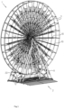
- FIG. 1 shows a schematic view of a preferred embodiment of a Ferris wheel 1 according to the invention is a position of use.
- the Ferris wheel 1 is moveable and suitable as fairground attraction.
- the Ferris wheel 1 is provided with a base 2, which can for example comprise a number of semi-trailers.
- the Ferris wheel 1 further comprises a first pair of masts 11, 12 and a second pair of masts 21, 22. Each pair of masts is moveable between the shown stretched position and a folded position.
- FIG. 2 schematically shows a part of the Ferris wheel according to the invention of figure 1 in more detail.
- the masts in each pair are hingedly coupled at the top side by means of a hinge S1.
- Each mast 11, 12, 21, 22 is hingedly mountable onto the base 2.
- the masts comprise a number of hingeable segments.
- the main shafts 11, 21 each have two hingeable segments and the auxiliary masts 12, 22 each have three hingeable segments.
- suitable actuators are provided.
- the actuators are hydraulic cylinders 17, which support on the base 2 and on the main shaft 11, 21 in each pair.
- the aforementioned European patent EP 2055362 of the same applicant describes an example of a suitable, foldable support structure for a Ferris wheel.
- the Ferris wheel 1 is as per usual made up of a number of spokes 10, which are interconnected at their distal outer ends by ring segments 3, which together form an outer ring of the Ferris wheel 1 on which gondolas (not shown) can be hung.
- the spokes 10 are connected at multiple positions along their length by means of further ring segments 4 and 5, which form further inner rings.
- a drive 6 is provided, which drives the outer ring of the Ferris wheel 1.
- Such a drive is known in the relevant technical field.
- the spokes 10 and the ring segments 3, 4, 5, further semi-trailers are for example provided.
- FIG. 3 schematically shows a part of the Ferris wheel according to the invention of figure 2 in more detail.
- the Ferris wheel 1 comprises two separate shafts 13, 23, which are in line on a rotational centreline R1.
- the first shaft 13 is mounted fixedly on the top of the first pair of masts 11, 12.
- a first spoke ring or spoke wheel 14 is arranged rotatably around the first shaft 13 by means of a first self-adjusting bearing.
- the second shaft 23 is mounted fixedly on the top of the second pair of masts 21, 22.
- a second spoke ring or spoke wheel 24 is arranged rotatably around the second shaft 23 by means of a second self-adjusting bearing.
- the first spoke ring 14 and the second spoke ring 24 are provided on the periphery thereof with first mounting openings 15, respectively second mounting openings 25, for mounting the spokes 10 at the location of the proximal ends thereof.
- the spokes 10 extend radially from the rotational centreline R1.
- each spoke 10 has two legs 9 that substantially run parallel, which are interconnected by means of a number of rods 7, 8.
- Each spoke 10 has a first mounting element 91 on an outer end of the first leg 9, which is arranged for mounting in one of the first mounting openings 15 in the first spoke ring 14.
- Each spoke 10 has a second mounting element 91 on an outer end of the second leg 9, which is arranged for mounting in one of the second mounting openings 25 in the second spoke ring 24.
- Each spoke 10 is further provided with a second crossbar 18, which connects the legs 9 near the outer ends and the mounting elements.
- the spokes are grouped in sets of two or three. In each set there is a main spoke 10. On the main spoke 10, one or two further spokes are mounted, for example in a hingeable manner. In the shown preferred embodiment, the spokes are grouped in sets of three with further spokes 10A and 10B which are substantially identical to the spokes 10. Each set of spokes has joint first and second mounting elements, which are mounted on the main spoke 10.
- the first spoke ring 14 is located near an outer end of the first shaft 13 and the second spoke ring 24 is located near an outer end of the second shaft 23.
- the first shaft 13 and the second shaft 23 function as stub axle.
- the spoke rings 14, 24 should be directed towards each other. When the Ferris wheel is in use, the distance between the spoke rings 14, 24 should substantially be corresponding to the distance between the double legs 9 of the spokes 10.
- the first shaft 13 and the second shaft 23 are mounted rigidly or, in other words, mounted in a fixed moment manner on the respective pair of masts, for example by means of a weld joint or by fixation with multiple pens.
- the spoke rings 14, 24 are, on the sides facing each other, each provided with a housing 16 respectively 26 for electricity, for example lighting.
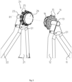
- Figure 4 shows a schematic detailed view of the Ferris wheel 1 according to the invention from a different point of view.
- Figure 4 shows the first spoke ring 14, wherein a number of spokes are mounted.
- the spoke leg 9 with the first mounting element 91 of some of the spokes is shown.
- the first mounting element 91 is provided with an additional connecting element 92 with an at least partially tapered shape.
- the additional connecting element is formed by two wings that are located on both sides of the first mounting element 91.
- the additional connecting element 92 can be embodied conical.
- first clamping element 151 is arranged near each first mounting opening 15 as well as first operating means 152, 153 for moving the first clamping element 151.
- first clamping element 151 is generally wedge-shaped.
- Suitable operating means comprise a spring-loaded pin and/or a cylinder 152, which is coupled to the first clamping element 151 by means of a coupling element 153.
- the pin can for example be pretensioned to move the clamping element outwards in radial direction, whereby the cylinder can actively move the clamping element inwards in radial direction.
- the second spoke ring 24 is embodied in a similar manner as the first spoke ring 14.
- the second mounting element 91 is embodied in a similar manner as the first mounting element 91.
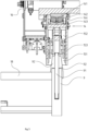
- Figure 5 shows the detailed view of figure 4 schematically in frontal view, partially in cross section.
- the first self-adjusting bearing 141 is shown in cross section.
- the bearing 141 has an inner ring 142 and an outer ring 143 with intermediate rolling elements 144.
- the bearing 141 is a barrel roller bearing and the rolling elements 144 are barrel-shaped.
- the barrel roller bearing has a double row.
- the method for assembling the Ferris wheel according to the invention comprises the following steps.
- the first pair of masts 11, 13 with the first shaft 13 is raised using suitable operating means (not shown) for the actuators 17.
- the second pair of masts 21, 22 with the second shaft 23 are raised using suitable operating means for the actuators 17.
- the first and second step can also be performed in reverse order or simultaneously.
- the first and second shaft 13, 23 are aligned on a joint rotational centreline R1.
- the base 2 can hereto be a platform that is equipped with a support system for moving the platform, as described in the European patent EP 3323479 of the same applicant.
- the known support system can be used to tilt the platform in order to align the first and second shaft 13, 23 and/or to set the desired distance between the first and second shaft. Due to the self-adjusting bearings for the spoke rings, the spoke rings are able to tilt.
- Various other aligning means can be used for this, among which aligning means that use light.
- the spokes 10 are plugged into the first spoke ring 14 and into the second spoke ring 24.
- the spokes 10 are hereto raised with winches. Preferably, two winches are used for this, which are mounted on the spokes.
- the first respectively second mounting elements 91 are preferably arranged as seekers and the first respectively second mounting openings are preferably arranged as search holes for cooperation with the seekers. Subsequently, the connection between the spokes and the spoke rings should be made in a fixed moment manner.
- the first clamping element 151 is moved radially outwards in the first spoke ring 14 such that it comes to lie against the additional connecting element 92 and with that forms a rigid connection. Furthermore, a second clamping element (not shown) is moved radially outwards in the second spoke ring 25 such that it comes to lie against the additional connecting element 92 and with that also forms a rigid connection.
- a fixed moment connection can be realized in an alternative way by at least partially complementary shapes of the first mounting elements 91 and (the surrounding of) the first mounting openings 15 respectively (the surrounding of) the second mounting openings 25.
- the spokes 10 are connected to the ring segments.
- a double outer ring is formed with the ring segments 3.
- a double inner ring is formed with the ring segments 5 and an intermediate double ring is formed with the ring segments 4.
- the Ferris wheel is further assembled in the usual way and gondolas (not shown) are for example hung on the outer rings.
- the first pair of masts 11, 12 with the first stub axle 13 and the second pair of masts 21, 22 with the second stub axle 23 can be lowered down to the folded position. This can be performed using the same operating means as for the actuators 17.
- the inventive idea is based on the insight that a Ferris wheel without a main shaft, but with two aligned, separate shafts, can reliably rotate due to the self-adjusting bearings and the inventive connecting means for realizing a fixed moment connection between the spokes and spoke rings.
- Each pair of masts is connected to each other at the top and supports one of the two shafts at the location of that connection.
- Each pair of masts with shaft can move independently between the folded and the stretched position.
Landscapes
- Pivots And Pivotal Connections (AREA)
- Roof Covering Using Slabs Or Stiff Sheets (AREA)
Abstract
Description
- The present invention relates to a Ferris wheel comprising two pairs of masts, wherein the masts in each pair are hingedly interconnected and wherein each pair of masts is moveable between a folded position and a stretched position, wherein the Ferris wheel is further provided with multiple spokes, two spoke rings for mounting the spokes and multiple ring segments for interconnection of the spokes.
- Such a mobile Ferris wheel is known in the relevant technical field. The European patent
EP2055362 of the same applicant for example describes a support structure for a mobile Ferris wheel. The known mobile Ferris wheel is intended to be a moveable (fairground) attraction and can be assembled and disassembled in a fast and safe manner. - The present invention aims to provide an improved mobile Ferris wheel that can be assembled and disassembled even faster and safer.
- The Ferris wheel according to the present invention is thereto characterized in that the Ferris wheel comprises a first shaft, which is mounted fixedly on the top of the first pair of masts, wherein a first of the two spoke rings is arranged rotatably around the first shaft, that the Ferris wheel further comprises a second shaft, which is mounted fixedly on the top of the second pair of masts, wherein a second of the two spoke rings is arranged rotatably around the second shaft, wherein, when the Ferris wheel is in use, the second shaft is substantially in line with the first shaft at a distance from the first shaft.
- The Ferris wheel according to the invention has the advantage that it no longer comprises a main shaft. Consequently, the use of a crane when assembling and disassembling the Ferris wheel is no longer needed. For the known Ferris wheels with main shaft, a crane is used when assembling in order to place the main shaft on the masts, and when disassembling in order to remove the main shaft from the masts. A crane takes up a lot of space and, when driving onto the site, one often has to wait for this space to be available. Assembling and disassembling the Ferris wheel according to the invention therefore costs less time and is cheaper. It is also safer, since there no longer has to be lifted a heavy main shaft onto the masts. Furthermore, a main shaft is generally custom made in a separate production step, which can now be omitted. The production of the Ferris wheel according to the invention is therefore cheaper than that of a Ferris wheel with main shaft.
- Such a Ferris wheel without main shaft is described in the Dutch patent
NL 2030798 - The Ferris wheel according to the present invention distinguishes itself from this by comprising self-adjusting bearings for the spoke rings, and by the spokes and spoke rings being arranged for realising a fixed moment connection.
- These new technical measures provide a degree of stiffness to the Ferris wheel without main shaft according to the present invention that is similar to the stiffness of a traditional Ferris wheel with a main shaft.
- In a first preferred embodiment each spoke has two legs, which substantially run parallel, which are interconnected by means of a number of rods, of which a first mounting element on an outer end of the one leg is arranged for mounting in the first spoke ring, wherein the first spoke ring has a number of first mounting openings, which are each arranged for accommodating a first mounting element, and a second mounting element on an outer end of the other leg is arranged for mounting in the second spoke ring, wherein the second spoke ring has a number of second mounting openings, which are each arranged for accommodating a second mounting element.
- The use of these double spokes attributes to the stiffness of the Ferris wheel according to the invention. Moreover, the assembly and disassembly happen faster when using double spokes. The stiffness can further be improved by providing the spoke with a first crossbar, which connects the legs near the outer ends.
- In a further preferred embodiment the shape of the first mounting element is at least partially complementary to the shape of the first spoke ring near the first mounting openings, and the shape of the second mounting element is at least partially complementary to the shape of the second spoke ring near the second mounting openings.
- The complementary shapes guarantee the intended fixed moment connection in an effective manner.
- In an even further preferred embodiment at least one moveable first clamping element is arranged near each first mounting opening, and the first spoke ring comprises first operating means for moving the first clamping element, and at least one moveable second clamping element is arranged near each second mounting opening, and the second spoke ring comprises second operating means for moving the second clamping element. By means of these inventive connecting means, the intended fixed moment connection is actively being achieved.
- Preferably, the first clamping element is generally wedge-shaped and the second clamping element is generally wedge-shaped.
- Preferably, the shape of the first mounting element is at least partially tapered and the shape of the second mounting element is at least partially tapered.
- According to a practical preferred embodiment the first mounting element is provided with an additional connecting element and the second mounting element is provided with an additional connecting element.
- In an elegant, preferred embodiment the spoke rings are mounted on outer ends of the first and second shaft which are facing each other. The first shaft and the second shaft can then be embodied as short as possible. The weight and the costs of short shafts are lower. A stub axle is for example very suitable as an application for both the first shaft and the second shaft.
- The present invention further relates to a method for assembling the Ferris wheel according to the invention, whereby the method comprises the following steps:
- a) jointly raising the first pair of masts with the first shaft to the stretched position;
- b) jointly raising the second pair of masts with the second shaft to the stretched position;
- c) outlining the first and second shaft on a common rotational centreline;
- d) mounting the spokes in the first spoke ring and in the second spoke ring by means of a fixed moment connection; and
- e) connecting the spokes with the ring segments.
- The invention will now be described in more detail with reference to the figures.
-
Figure 1 shows a schematic view of a Ferris wheel according to the invention in a position of use; -
Figure 2 schematically shows a part of the Ferris wheel according to the invention offigure 1 in more detail; -
Figure 3 schematically shows a part of the Ferris wheel according to the invention offigure 2 in more detail; -
Figure 4 schematically shows a detailed view of the Ferris wheel according to the invention from a different point of view; and -
Figure 5 schematically shows the detailed view offigure 4 in frontal view, partially in cross section. -
Figure 1 shows a schematic view of a preferred embodiment of a Ferris wheel 1 according to the invention is a position of use. The Ferris wheel 1 is moveable and suitable as fairground attraction. - The Ferris wheel 1 is provided with a
base 2, which can for example comprise a number of semi-trailers. The Ferris wheel 1 further comprises a first pair ofmasts masts -
Figure 2 schematically shows a part of the Ferris wheel according to the invention offigure 1 in more detail. In the shown preferred embodiment the masts in each pair are hingedly coupled at the top side by means of a hinge S1. Eachmast base 2. In each pair, the masts comprise a number of hingeable segments. In the shown preferred embodiment, themain shafts auxiliary masts hydraulic cylinders 17, which support on thebase 2 and on themain shaft EP 2055362 of the same applicant describes an example of a suitable, foldable support structure for a Ferris wheel. - The Ferris wheel 1 is as per usual made up of a number of
spokes 10, which are interconnected at their distal outer ends by ring segments 3, which together form an outer ring of the Ferris wheel 1 on which gondolas (not shown) can be hung. Thespokes 10 are connected at multiple positions along their length by means of further ring segments 4 and 5, which form further inner rings. In the shown preferred embodiment a drive 6 is provided, which drives the outer ring of the Ferris wheel 1. Such a drive is known in the relevant technical field. - For the transport of the remaining parts of the attraction, in this example the
spokes 10 and the ring segments 3, 4, 5, further semi-trailers are for example provided. -
Figure 3 schematically shows a part of the Ferris wheel according to the invention offigure 2 in more detail. - According to the invention, the Ferris wheel 1 comprises two
separate shafts first shaft 13 is mounted fixedly on the top of the first pair ofmasts wheel 14 is arranged rotatably around thefirst shaft 13 by means of a first self-adjusting bearing. Thesecond shaft 23 is mounted fixedly on the top of the second pair ofmasts wheel 24 is arranged rotatably around thesecond shaft 23 by means of a second self-adjusting bearing. - The
first spoke ring 14 and thesecond spoke ring 24 are provided on the periphery thereof with first mountingopenings 15, respectively second mountingopenings 25, for mounting thespokes 10 at the location of the proximal ends thereof. After the assembly, thespokes 10 extend radially from the rotational centreline R1. In the shown preferred embodiment, each spoke 10 has twolegs 9 that substantially run parallel, which are interconnected by means of a number ofrods 7, 8. Each spoke 10 has a first mountingelement 91 on an outer end of thefirst leg 9, which is arranged for mounting in one of the first mountingopenings 15 in thefirst spoke ring 14. Each spoke 10 has a second mountingelement 91 on an outer end of thesecond leg 9, which is arranged for mounting in one of the second mountingopenings 25 in thesecond spoke ring 24. Each spoke 10 is further provided with asecond crossbar 18, which connects thelegs 9 near the outer ends and the mounting elements. - Preferably, the spokes are grouped in sets of two or three. In each set there is a
main spoke 10. On the main spoke 10, one or two further spokes are mounted, for example in a hingeable manner. In the shown preferred embodiment, the spokes are grouped in sets of three withfurther spokes spokes 10. Each set of spokes has joint first and second mounting elements, which are mounted on themain spoke 10. - The
first spoke ring 14 is located near an outer end of thefirst shaft 13 and thesecond spoke ring 24 is located near an outer end of thesecond shaft 23. Thefirst shaft 13 and thesecond shaft 23 function as stub axle. The spoke rings 14, 24 should be directed towards each other. When the Ferris wheel is in use, the distance between the spoke rings 14, 24 should substantially be corresponding to the distance between thedouble legs 9 of thespokes 10. - The
first shaft 13 and thesecond shaft 23 are mounted rigidly or, in other words, mounted in a fixed moment manner on the respective pair of masts, for example by means of a weld joint or by fixation with multiple pens. - Optionally, the spoke rings 14, 24 are, on the sides facing each other, each provided with a
housing 16 respectively 26 for electricity, for example lighting. -
Figure 4 shows a schematic detailed view of the Ferris wheel 1 according to the invention from a different point of view.Figure 4 shows thefirst spoke ring 14, wherein a number of spokes are mounted. Thespoke leg 9 with the first mountingelement 91 of some of the spokes is shown. The first mountingelement 91 is provided with an additional connectingelement 92 with an at least partially tapered shape. In the shown preferred embodiment, the additional connecting element is formed by two wings that are located on both sides of the first mountingelement 91. As an alternative, the additional connectingelement 92 can be embodied conical. - In the
spoke wheel 14 at least one moveablefirst clamping element 151 is arranged near each first mountingopening 15 as well as first operating means 152, 153 for moving thefirst clamping element 151. In the shown preferred embodiment thefirst clamping element 151 is generally wedge-shaped. Suitable operating means comprise a spring-loaded pin and/or acylinder 152, which is coupled to thefirst clamping element 151 by means of acoupling element 153. The pin can for example be pretensioned to move the clamping element outwards in radial direction, whereby the cylinder can actively move the clamping element inwards in radial direction. - For the sake of completeness, it is noted that the
second spoke ring 24 is embodied in a similar manner as thefirst spoke ring 14. Furthermore, for each spoke the second mountingelement 91 is embodied in a similar manner as the first mountingelement 91. - By active placement of the
first clamping element 151 against the additional connectingelement 92, a fixed moment connection can be realized for each spoke in the spoke ring. -
Figure 5 shows the detailed view offigure 4 schematically in frontal view, partially in cross section. Infigure 5 the first self-adjustingbearing 141 is shown in cross section. Thebearing 141 has aninner ring 142 and anouter ring 143 with intermediaterolling elements 144. In the shown preferred embodiment thebearing 141 is a barrel roller bearing and the rollingelements 144 are barrel-shaped. Preferably, the barrel roller bearing has a double row. - The method for assembling the Ferris wheel according to the invention comprises the following steps.
- In a first step, the first pair of
masts first shaft 13 is raised using suitable operating means (not shown) for theactuators 17. - In a second step, the second pair of
masts second shaft 23 are raised using suitable operating means for theactuators 17. The first and second step can also be performed in reverse order or simultaneously. - In a third step, the first and
second shaft base 2 can hereto be a platform that is equipped with a support system for moving the platform, as described in the European patentEP 3323479 of the same applicant. The known support system can be used to tilt the platform in order to align the first andsecond shaft - In a fourth step, the
spokes 10 are plugged into thefirst spoke ring 14 and into thesecond spoke ring 24. Thespokes 10 are hereto raised with winches. Preferably, two winches are used for this, which are mounted on the spokes. The first respectively second mountingelements 91 are preferably arranged as seekers and the first respectively second mounting openings are preferably arranged as search holes for cooperation with the seekers. Subsequently, the connection between the spokes and the spoke rings should be made in a fixed moment manner. - In the shown preferred embodiment of the Ferris wheel, the
first clamping element 151 is moved radially outwards in thefirst spoke ring 14 such that it comes to lie against the additional connectingelement 92 and with that forms a rigid connection. Furthermore, a second clamping element (not shown) is moved radially outwards in thesecond spoke ring 25 such that it comes to lie against the additional connectingelement 92 and with that also forms a rigid connection. - A fixed moment connection can be realized in an alternative way by at least partially complementary shapes of the first mounting
elements 91 and (the surrounding of) the first mountingopenings 15 respectively (the surrounding of) the second mountingopenings 25. - In a fifth step, the
spokes 10 are connected to the ring segments. In the shown preferred embodiment, a double outer ring is formed with the ring segments 3. A double inner ring is formed with the ring segments 5 and an intermediate double ring is formed with the ring segments 4. - In subsequent steps the Ferris wheel is further assembled in the usual way and gondolas (not shown) are for example hung on the outer rings.
- When disassembling the Ferris wheel, after removing the gondolas, the ring segments, and spokes, the first pair of
masts first stub axle 13 and the second pair ofmasts second stub axle 23 can be lowered down to the folded position. This can be performed using the same operating means as for theactuators 17. - The inventive idea is based on the insight that a Ferris wheel without a main shaft, but with two aligned, separate shafts, can reliably rotate due to the self-adjusting bearings and the inventive connecting means for realizing a fixed moment connection between the spokes and spoke rings. Each pair of masts is connected to each other at the top and supports one of the two shafts at the location of that connection. Each pair of masts with shaft can move independently between the folded and the stretched position.
- It generally applies that suitable hinges, operating means and mounting means are in itself known in the relevant technical field.
- The invention is therefore not limited to the described and shown preferred embodiment, but extends to any embodiment that falls within the scope of the scope of protection, as defined in the claims and seen in the light of the preceding description and accompanying figures.
Claims (12)
- Ferris wheel (1), comprising two pairs of masts (11, 21; 21, 22), wherein the masts in each pair are hingedly interconnected and wherein each pair of masts is moveable between a folded position and a stretched position, wherein the Ferris wheel is further provided with multiple spokes (10), two spoke rings (14, 24) for mounting the spokes and multiple ring segments (3, 4, 5) for interconnection of the spokes, characterized in that the Ferris wheel comprises a first shaft (13) which is mounted fixedly on the top of the first pair of masts (11, 12), wherein a first (14) of the two spoke rings is arranged rotatably around the first shaft by means of a first self-adjusting bearing (141), that the Ferris wheel further comprises a second shaft (23) which is mounted fixedly on the top of the second pair of masts (21, 22), wherein a second (24) of the two spoke rings is arranged rotatably around the second shaft by means of a second self-adjusting bearing (141), wherein, when the Ferris wheel is in use, the second shaft is substantially in line with the first shaft at a distance from the first shaft, wherein the spokes and the spoke rings are arranged for realizing a fixed moment connection.
- Ferris wheel (1) according to claim 1, wherein each spoke (10) has two legs (9) which substantially run parallel, which are interconnected by means of a number of rods (7,8), of which a first mounting element (91) on an outer end of a first leg is arranged for mounting in the first spoke ring (14), wherein the first spoke ring has a number of first mounting openings (15), which are each arranged for accommodating a first mounting element, and a second mounting element (91) on an outer end of a second leg is arranged for mounting in the second spoke ring (24), wherein the second spoke ring has a number of second mounting openings (25), which are each arranged for accommodating a second mounting element.
- Ferris wheel (1) according to claim 2, wherein the shape of the first mounting element (91) is at least partially complementary to the shape of the first spoke ring (14) near the first mounting openings (15), and wherein the shape of the second mounting element (91) is at least partially complementary to the shape of the second spoke ring (24) near the second mounting openings (25).
- Ferris wheel (1) according to claim 2 or 3, wherein at least one moveable first clamping element (151) is arranged near each first mounting opening (15), and wherein the first spoke ring (14) comprises first operating means (152) for moving the first clamping element, and wherein at least one moveable second clamping element (151) is arranged near each second mounting opening (25), and wherein the second spoke ring (24) comprises second operating means (152) for moving the second clamping element (151).
- Ferris wheel (1) according to claim 4, wherein the first clamping element (151) is generally wedge-shaped, and wherein the second clamping element (151) is generally wedge-shaped.
- Ferris wheel (1) according to claim 2, 3, 4 or 5, wherein the shape of the first mounting element (91) is at least partially tapered, and wherein the shape of the second mounting element (91) is at least partially tapered.
- Ferris wheel (1) according to one of the preceding claims 2-6, wherein the first mounting element (91) is provided with an additional connecting element (92), and wherein the second mounting element (91) is provided with an additional connecting element (92).
- Ferris wheel (1) according to one of the preceding claims 2-7, wherein the spoke (10) is provided with a first crossbar (18) which connects the legs (9) near the outer ends.
- Ferris wheel (1) according to one of the preceding claims, wherein the spoke rings (14, 24) are mounted on outer ends of the first (13) and second shaft (23) which are facing each other.
- Ferris wheel (1) according to one of the preceding claims, wherein the first shaft (23) comprises a first stub axle, and wherein the second shaft (23) comprises a second stub axle.
- Method for building the Ferris wheel according to one of the preceding claims, whereby the method comprises the following stepsa) jointly raising the first pair of masts (11, 12) with the first shaft (13) to the stretched position;b) jointly raising the second pair of masts (21, 22) with the second shaft (23) to the stretched position;c) outlining the first and second shaft on a common rotational centreline (R1);d) mounting the spokes (10) in the first spoke ring (14) and in the second spoke ring (24) by means of a fixed moment connection; ande) connecting the spokes with the ring segments (3, 4, 5).
- Method according to claim 11 for building the Ferris wheel according to claim 4, whereby step d) comprises the following partial steps for each spoke (10)d1) moving the first clamping element (151) by means of the first operating means (152) near the respective first mounting opening (15) of the first spoke ring (14) for fixed moment connection of the respective first mounting element (91); andd2) moving the second clamping element (151) by means of the second operating means (152) near the respective second mounting opening (25) of the second spoke ring (24) for fixed moment connection of the respective second mounting element (91).
Applications Claiming Priority (1)
| Application Number | Priority Date | Filing Date | Title |
|---|---|---|---|
| NL2035513A NL2035513B1 (en) | 2023-07-31 | 2023-07-31 | IMPROVED MOBILE FERRIS WHEEL WITHOUT MAIN AXIS AND METHOD FOR ASSEMBLING THE FERRIS WHEEL |
Publications (2)
| Publication Number | Publication Date |
|---|---|
| EP4501426A1 true EP4501426A1 (en) | 2025-02-05 |
| EP4501426B1 EP4501426B1 (en) | 2026-05-13 |
Family
ID=92708390
Family Applications (1)
| Application Number | Title | Priority Date | Filing Date |
|---|---|---|---|
| EP24190592.6A Active EP4501426B1 (en) | 2023-07-31 | 2024-07-24 | Improved mobile ferris wheel without main shaft and method for building the ferris wheel |
Country Status (2)
| Country | Link |
|---|---|
| EP (1) | EP4501426B1 (en) |
| NL (1) | NL2035513B1 (en) |
Citations (6)
| Publication number | Priority date | Publication date | Assignee | Title |
|---|---|---|---|---|
| US2590934A (en) * | 1949-08-26 | 1952-04-01 | William G Catlett | Portable ferris wheel |
| US20030162596A1 (en) * | 2002-02-26 | 2003-08-28 | Kroon Louisito Johannes Eusebio | Ferris wheel |
| EP2055362A1 (en) | 2007-10-29 | 2009-05-06 | K.I.G. Heerenveen B.V. | Upright support structure for a fairground attraction, in particular a ferris wheel |
| NL2015544B1 (en) * | 2015-10-02 | 2017-04-21 | Cobra Beheer Bv | Wheel and methods of assembling. |
| EP3323479A1 (en) | 2016-11-22 | 2018-05-23 | K.I.G. Heerenveen B.V. | Platform with support system configured to move the platform |
| NL2030798B1 (en) | 2022-02-01 | 2023-08-11 | Kig Heerenveen Bv | IMPROVED MOBILE FERRIS WHEEL AND METHOD FOR BUILDING THE FERRIS WHEEL |
-
2023
- 2023-07-31 NL NL2035513A patent/NL2035513B1/en active
-
2024
- 2024-07-24 EP EP24190592.6A patent/EP4501426B1/en active Active
Patent Citations (7)
| Publication number | Priority date | Publication date | Assignee | Title |
|---|---|---|---|---|
| US2590934A (en) * | 1949-08-26 | 1952-04-01 | William G Catlett | Portable ferris wheel |
| US20030162596A1 (en) * | 2002-02-26 | 2003-08-28 | Kroon Louisito Johannes Eusebio | Ferris wheel |
| EP2055362A1 (en) | 2007-10-29 | 2009-05-06 | K.I.G. Heerenveen B.V. | Upright support structure for a fairground attraction, in particular a ferris wheel |
| EP2055362B1 (en) * | 2007-10-29 | 2011-12-21 | K.I.G. Heerenveen B.V. | Upright support structure for a fairground attraction, in particular a ferris wheel |
| NL2015544B1 (en) * | 2015-10-02 | 2017-04-21 | Cobra Beheer Bv | Wheel and methods of assembling. |
| EP3323479A1 (en) | 2016-11-22 | 2018-05-23 | K.I.G. Heerenveen B.V. | Platform with support system configured to move the platform |
| NL2030798B1 (en) | 2022-02-01 | 2023-08-11 | Kig Heerenveen Bv | IMPROVED MOBILE FERRIS WHEEL AND METHOD FOR BUILDING THE FERRIS WHEEL |
Also Published As
| Publication number | Publication date |
|---|---|
| NL2035513B1 (en) | 2025-02-11 |
| EP4501426B1 (en) | 2026-05-13 |
Similar Documents
| Publication | Publication Date | Title |
|---|---|---|
| EP2055362B1 (en) | Upright support structure for a fairground attraction, in particular a ferris wheel | |
| EP4218978A1 (en) | Improved mobile ferris wheel and method for building the ferris wheel | |
| KR101033127B1 (en) | Motor overhaul | |
| US8739988B2 (en) | Pinned connection system for crane column segments | |
| CN104279131B (en) | It is lifted tower segments | |
| US7954657B2 (en) | Connection system for crane boom segments | |
| RU2509713C2 (en) | Self-propelled hoisting crane and method of its assembly (versions) | |
| EP4501426B1 (en) | Improved mobile ferris wheel without main shaft and method for building the ferris wheel | |
| WO2015089640A1 (en) | Apparatus for transporting a load | |
| GB2477078A (en) | Magnus Effect Rotor Apparatus | |
| KR100285300B1 (en) | Large rotor disassembly and assembly system | |
| US3002753A (en) | Foldable and portable ferris wheel | |
| CN120331821A (en) | Lightweight assembly equipment and installation method for subway tunnel steel ring segments | |
| CN110168216A (en) | Turbine system | |
| CN113738584A (en) | Fan blade assembling auxiliary device and assembling method | |
| EP3970821B1 (en) | Support construction for a transportable attraction for amusement rides and method for raising the support construction | |
| US20240109368A1 (en) | Method and apparatus for handling components of a vehicle wheel assembly | |
| JP2012066882A (en) | Mobile crane | |
| JP7462824B1 (en) | Method for removing assembly jig, and assembly jig | |
| CN120607196A (en) | Self-climbing hoisting equipment and method for installing wind turbine generator set | |
| BE1030247B1 (en) | SPOKES SET FOR A FERRIS WHEEL | |
| KR20210150736A (en) | Joining of apparatus and joining method of composite plastic tubular body and shaft joint member | |
| CN221720300U (en) | A pin lifting device | |
| CN220739958U (en) | Assembling and positioning device for bridge steel arch rib | |
| RU207783U1 (en) | Mobile ferris wheel |
Legal Events
| Date | Code | Title | Description |
|---|---|---|---|
| PUAI | Public reference made under article 153(3) epc to a published international application that has entered the european phase |
Free format text: ORIGINAL CODE: 0009012 |
|
| STAA | Information on the status of an ep patent application or granted ep patent |
Free format text: STATUS: THE APPLICATION HAS BEEN PUBLISHED |
|
| AK | Designated contracting states |
Kind code of ref document: A1 Designated state(s): AL AT BE BG CH CY CZ DE DK EE ES FI FR GB GR HR HU IE IS IT LI LT LU LV MC ME MK MT NL NO PL PT RO RS SE SI SK SM TR |
|
| STAA | Information on the status of an ep patent application or granted ep patent |
Free format text: STATUS: REQUEST FOR EXAMINATION WAS MADE |
|
| 17P | Request for examination filed |
Effective date: 20250519 |
|
| GRAP | Despatch of communication of intention to grant a patent |
Free format text: ORIGINAL CODE: EPIDOSNIGR1 |
|
| STAA | Information on the status of an ep patent application or granted ep patent |
Free format text: STATUS: GRANT OF PATENT IS INTENDED |
|
| RIC1 | Information provided on ipc code assigned before grant |
Ipc: A63G 27/00 20060101AFI20250929BHEP |
|
| INTG | Intention to grant announced |
Effective date: 20251028 |
|
| GRAS | Grant fee paid |
Free format text: ORIGINAL CODE: EPIDOSNIGR3 |
|
| GRAJ | Information related to disapproval of communication of intention to grant by the applicant or resumption of examination proceedings by the epo deleted |
Free format text: ORIGINAL CODE: EPIDOSDIGR1 |
|
| GRAL | Information related to payment of fee for publishing/printing deleted |
Free format text: ORIGINAL CODE: EPIDOSDIGR3 |
|
| STAA | Information on the status of an ep patent application or granted ep patent |
Free format text: STATUS: REQUEST FOR EXAMINATION WAS MADE |
|
| GRAP | Despatch of communication of intention to grant a patent |
Free format text: ORIGINAL CODE: EPIDOSNIGR1 |
|
| STAA | Information on the status of an ep patent application or granted ep patent |
Free format text: STATUS: GRANT OF PATENT IS INTENDED |
|
| INTC | Intention to grant announced (deleted) | ||
| INTG | Intention to grant announced |
Effective date: 20260223 |
|
| GRAA | (expected) grant |
Free format text: ORIGINAL CODE: 0009210 |
|
| STAA | Information on the status of an ep patent application or granted ep patent |
Free format text: STATUS: THE PATENT HAS BEEN GRANTED |
|
| AK | Designated contracting states |
Kind code of ref document: B1 Designated state(s): AL AT BE BG CH CY CZ DE DK EE ES FI FR GB GR HR HU IE IS IT LI LT LU LV MC ME MK MT NL NO PL PT RO RS SE SI SK SM TR |
|
| REG | Reference to a national code |
Ref country code: CH Ref legal event code: F10 Free format text: ST27 STATUS EVENT CODE: U-0-0-F10-F00 (AS PROVIDED BY THE NATIONAL OFFICE) Effective date: 20260513 |