EP4501399A1 - Neutron capture therapy device and collimator - Google Patents
Neutron capture therapy device and collimator Download PDFInfo
- Publication number
- EP4501399A1 EP4501399A1 EP23780532.0A EP23780532A EP4501399A1 EP 4501399 A1 EP4501399 A1 EP 4501399A1 EP 23780532 A EP23780532 A EP 23780532A EP 4501399 A1 EP4501399 A1 EP 4501399A1
- Authority
- EP
- European Patent Office
- Prior art keywords
- neutron
- collimator
- hole portion
- target
- disposed
- Prior art date
- Legal status (The legal status is an assumption and is not a legal conclusion. Google has not performed a legal analysis and makes no representation as to the accuracy of the status listed.)
- Pending
Links
Images



Classifications
-
- A—HUMAN NECESSITIES
- A61—MEDICAL OR VETERINARY SCIENCE; HYGIENE
- A61N—ELECTROTHERAPY; MAGNETOTHERAPY; RADIATION THERAPY; ULTRASOUND THERAPY
- A61N5/00—Radiation therapy
- A61N5/10—X-ray therapy; Gamma-ray therapy; Particle-irradiation therapy
-
- A—HUMAN NECESSITIES
- A61—MEDICAL OR VETERINARY SCIENCE; HYGIENE
- A61N—ELECTROTHERAPY; MAGNETOTHERAPY; RADIATION THERAPY; ULTRASOUND THERAPY
- A61N5/00—Radiation therapy
- A61N5/10—X-ray therapy; Gamma-ray therapy; Particle-irradiation therapy
- A61N5/1042—X-ray therapy; Gamma-ray therapy; Particle-irradiation therapy with spatial modulation of the radiation beam within the treatment head
- A61N5/1045—X-ray therapy; Gamma-ray therapy; Particle-irradiation therapy with spatial modulation of the radiation beam within the treatment head using a multi-leaf collimator, e.g. for intensity modulated radiation therapy or IMRT
-
- A—HUMAN NECESSITIES
- A61—MEDICAL OR VETERINARY SCIENCE; HYGIENE
- A61N—ELECTROTHERAPY; MAGNETOTHERAPY; RADIATION THERAPY; ULTRASOUND THERAPY
- A61N5/00—Radiation therapy
- A61N5/10—X-ray therapy; Gamma-ray therapy; Particle-irradiation therapy
- A61N5/1077—Beam delivery systems
-
- A—HUMAN NECESSITIES
- A61—MEDICAL OR VETERINARY SCIENCE; HYGIENE
- A61N—ELECTROTHERAPY; MAGNETOTHERAPY; RADIATION THERAPY; ULTRASOUND THERAPY
- A61N5/00—Radiation therapy
- A61N5/10—X-ray therapy; Gamma-ray therapy; Particle-irradiation therapy
- A61N5/1077—Beam delivery systems
- A61N5/1078—Fixed beam systems
-
- A—HUMAN NECESSITIES
- A61—MEDICAL OR VETERINARY SCIENCE; HYGIENE
- A61N—ELECTROTHERAPY; MAGNETOTHERAPY; RADIATION THERAPY; ULTRASOUND THERAPY
- A61N5/00—Radiation therapy
- A61N5/10—X-ray therapy; Gamma-ray therapy; Particle-irradiation therapy
- A61N2005/1085—X-ray therapy; Gamma-ray therapy; Particle-irradiation therapy characterised by the type of particles applied to the patient
- A61N2005/109—Neutrons
-
- A—HUMAN NECESSITIES
- A61—MEDICAL OR VETERINARY SCIENCE; HYGIENE
- A61N—ELECTROTHERAPY; MAGNETOTHERAPY; RADIATION THERAPY; ULTRASOUND THERAPY
- A61N5/00—Radiation therapy
- A61N5/10—X-ray therapy; Gamma-ray therapy; Particle-irradiation therapy
- A61N2005/1092—Details
- A61N2005/1094—Shielding, protecting against radiation
-
- A—HUMAN NECESSITIES
- A61—MEDICAL OR VETERINARY SCIENCE; HYGIENE
- A61N—ELECTROTHERAPY; MAGNETOTHERAPY; RADIATION THERAPY; ULTRASOUND THERAPY
- A61N5/00—Radiation therapy
- A61N5/10—X-ray therapy; Gamma-ray therapy; Particle-irradiation therapy
- A61N2005/1092—Details
- A61N2005/1095—Elements inserted into the radiation path within the system, e.g. filters or wedges
Definitions
- the present disclosure relates to a neutron capture therapy device and a collimator.
- boron neutron capture therapy using a boron compound is known as neutron capture therapy that irradiates cancer cells with neutron rays to kill the cancer cells.
- neutron capture therapy boron that is taken into cancer cells in advance is irradiated with neutron rays and the cancer cells are selectively destroyed using the scattering of heavy charged particles that is caused by the irradiation of boron with the neutron rays.
- a neutron capture therapy device disclosed in PTL 1 decelerates neutron rays generated from a target with a deceleration member, forms an irradiation field with a collimator, and irradiates an irradiation target with the neutron rays. Accordingly, the neutron rays can be decelerated to an appropriate energy by the deceleration member.
- an object of the present disclosure is to provide a neutron capture therapy device and a collimator that can shorten a treatment time by increasing neutron flux with which an irradiation target is to be irradiated.
- a neutron capture therapy device includes an accelerator that generates a particle beam, a target that generates a neutron ray by reacting with the particle beam, a collimator that includes a hole portion penetrating in an irradiating direction of the neutron ray and forms an irradiation field of the neutron ray generated from the target, and a deceleration member that decelerates the neutron ray generated from the target, in which a part of the deceleration member is disposed in the hole portion of the collimator.
- the neutron capture therapy device includes a collimator that includes a hole portion penetrating in an irradiating direction of the neutron ray and forms an irradiation field of the neutron ray generated from the target. For this reason, the neutron ray passes through the hole portion of the collimator, and the irradiation target is irradiated with the neutron ray in the irradiation field corresponding to the shape of the collimator. Further, in a state where the neutron ray passes through the deceleration member corresponding to a predetermined distance from the target and is thus adjusted to an appropriate energy, the irradiation target is irradiated with the neutron ray.
- the target can be disposed close to the irradiation target as much as the deceleration member is disposed in the hole portion of the collimator.
- neutron flux can be increased. From the above, it is possible to shorten a treatment time by increasing neutron flux with which an irradiation target is to be irradiated.
- At least a part of the collimator may be detachable. In this case, it is possible to easily adjust the size of the deceleration member that is disposed in the collimator by replacing the collimator.
- the collimator may include a protrusion part protruding from a wall surface, and the deceleration member may be provided in the hole portion of the protrusion part. Since the deceleration member can be disposed even at a position closer to the irradiation target than the wall surface in this case, a distance between the target and the irradiation target can be shortened.
- At least a part of the protrusion part may be detachable from the wall surface. Accordingly, a part of the collimator can be easily detached from the wall surface. That is, it is possible to easily adjust the size of the deceleration member that is disposed in the hole portion of the collimator.
- the deceleration member may be disposed in the hole portion of the protrusion part over a range of a half or more of the protrusion part in the irradiating direction. Accordingly, since the deceleration member that is disposed in the hole portion of the protrusion part can be increased in size, a distance between the target and the irradiation target can be shortened by that much.
- the wall surface may extend perpendicular to the irradiating direction.
- the protrusion part has a simple configuration in which the protrusion part protrudes in the irradiating direction.
- a gamma ray blocking member may be disposed on a side facing an irradiation target in the hole portion of the collimator.
- the gamma ray blocking member is disposed on the downstream side of the deceleration member in the irradiating direction. Therefore, since the gamma ray blocking member is disposed on a side facing the irradiation target in the hole portion, a large space in which the deceleration member can be disposed can be ensured in the hole portion.
- a collimator according to another aspect of the present disclosure is a collimator that forms an irradiation field of a neutron ray, and includes a hole portion that penetrates in an irradiating direction of the neutron ray, in which a deceleration member that decelerates the neutron is disposed in the hole portion.
- a neutron capture therapy device and a collimator that can shorten a treatment time by increasing neutron flux with which an irradiation target is to be irradiated.
- a neutron capture therapy device 1 shown in Fig. 1 is an apparatus that is used to treat cancer using boron neutron capture therapy (BNCT).
- BNCT boron neutron capture therapy
- a tumor of a patient 50 who lies on a treatment table 51 to which boron ( 10 B) is administered is irradiated with neutron rays N.
- the neutron capture therapy device 1 includes an accelerator 2.
- the accelerator 2 accelerates charged particles such as negative ions to emit charged particle beams R.
- the accelerator 2 is formed of, for example, a cyclotron.
- the charged particle beam R is a proton beam that is generated in a case where charges are removed from negative ions.
- the accelerator is not limited to the cyclotron, and may be a synchrotron, a synchrocyclotron, a linear accelerator, an electrostatic accelerator, or the like.
- the charged particle beams R emitted from the accelerator 2 are sent to a neutron ray generating unit M.
- the neutron ray generating unit M includes a beam duct 9 (transport path) and a target 10.
- the charged particle beams R emitted from the accelerator 2 pass through the beam duct 9 and travel toward the target 10 disposed at an end portion of the beam duct 9.
- a plurality of quadrupole electromagnets 4 and a scanning electromagnet 6 are provided along the beam duct 9. The plurality of quadrupole electromagnets 4 are used, for example, to adjust the beam diameter of the charged particle beam R using an electromagnet.
- the scanning electromagnet 6 is to scan the charged particle beams R and to control the irradiation of the target 10 with the charged particle beams R.
- the scanning electromagnet 6 controls a position at which the target 10 is irradiated with the charged particle beams R.
- the neutron capture therapy device 1 includes a neutron generating unit 100 that irradiates the target 10 with the charged particle beams R to generate neutron rays N and emits the neutron rays N toward the patient 50.
- the neutron generating unit 100 includes the target 10, a shield member 8, a deceleration member 39, and a collimator 20.
- the target 10 is to generate neutron rays N in a case where the target 10 is irradiated with the charged particle beams R.
- the target 10 is a solid member made of a material that generates neutron rays by being irradiated with charged particle beams.
- the target 10 is made of, for example, beryllium (Be), lithium (Li), tantalum (Ta), or tungsten (W), and has, for example, the shape of a disk-shaped solid having a diameter of 160 mm.
- the target 10 is not limited to a disk shape and may have other shapes.
- the deceleration member 39 is to decelerate the neutron rays N (is to reduce the energy of the neutron rays N) generated by the target 10.
- the deceleration member 39 may have a laminated structure including a layer 39A that mainly decelerates fast neutrons included in the neutron rays N and a layer 39B that mainly decelerates epithermal neutrons included in the neutron rays N.
- a substance having a large total cross-sectional area for neutrons having an electron-volt of 40 keV or more is employed as the material of the deceleration member 39.
- examples of the material of the deceleration member 39 include CaF 2 , MgF 2 , AlF 3 , D 2 O, polyethylene, and the like.
- the shield member 8 is to block the generated neutron rays N and gamma rays and the like generated with the generation of the neutron rays N so that the generated neutron rays N and the gamma rays and the like are not released to the outside.
- the shield member 8 is provided to surround the deceleration member 39. An upper portion and a lower portion of the shield member 8 extend to an upstream side of the charged particle beam R more than the deceleration member 39.
- a substance having a large total cross-sectional area for neutrons having an electron-volt of 0.5 eV or less is employed as a material of a neutron blocking member of the shield member 8.
- Examples of the material of the neutron blocking member include Li, boron, cadmium, polyethylene, and the like. A substance having a large total cross-sectional area for gamma rays is employed as a material of a gamma ray blocking member of the shield member 8. Examples of the material of the gamma ray blocking member include lead, iron, and the like.
- the collimator 20 is to shape an irradiation field of the neutron rays N and includes an opening 20a through which the neutron rays N pass.
- the collimator 20 is, for example, a block-shaped member including a hole portion 21 at a center thereof.
- an irradiation axis of the charged particle beam R may be referred to as a reference line CL.
- the reference line CL corresponds to a center position in the irradiation with the neutron rays N.
- the direction refers to an irradiating direction of the charged particle beams R and the neutron rays N.
- the shield member 8 includes a main body 11, an outer layer 12, and a wall part 13.
- the main body 11 is disposed to surround the reference line CL.
- the main body 11 includes hole portions 11a and 11b extending along the reference line CL.
- the hole portion 11a is disposed on an upstream side in the irradiating direction D1, and the hole portion 11b is disposed on a downstream side.
- the hole portion 11a is an internal space that guides the charged particle beams R traveling toward the target 10.
- the hole portion 11b is an internal space in which the deceleration member 39 is disposed.
- the outer layer 12 is disposed on the outer periphery of the main body 11 in a direction orthogonal to the reference line CL.
- the wall part 13 is disposed at an end portion of the main body 11 on the downstream side in the irradiating direction D1.
- the wall part 13 extends perpendicular to the reference line CL.
- the wall part 13 functions as a partition wall that separates an accelerator room 101 (see Fig. 1 ) in which the accelerator 2 is disposed and a treatment room 102 in which the treatment table 51 (see Fig. 1 ) is disposed.
- a downstream wall surface 13a of the wall part 13 in the irradiating direction D1 extends perpendicular to the irradiating direction D1 in the treatment room 102.
- An upstream wall surface 13b of the wall part 13 in the irradiating direction D1 extends perpendicular to the irradiating direction D1 in the accelerator room 101.
- the wall part 13 is connected to a floor at a lower end thereof and is connected to a ceiling at an upper end thereof. The floor and the ceiling also function as a shield member that blocks radiation.
- the collimator 20 is formed in the wall part 13 at a position of the reference line CL.
- the hole portion 21 penetrating in the irradiating direction D1 is formed in the wall part 13, so that the collimator 20 is formed.
- the hole portion 21 includes inner peripheral surfaces 21a, 21b, and 21c in order from the upstream side to the downstream side in the irradiating direction D1.
- the inner peripheral surface 21a is a cylindrical surface having the same inner diameter as the inner diameter of the hole portion 11b of the main body 11.
- the inner peripheral surface 21b is a surface having an inclined cross-sectional shape such that an inner diameter thereof is reduced toward the downstream side in the irradiating direction D1.
- the inner peripheral surface 21c is a cylindrical surface having an inner diameter smaller than that of the inner peripheral surface 21a.
- the collimator 20 is adapted to include a narrowing portion 22 that protrudes from the inner peripheral surface 21a to an inner peripheral side.
- the narrowing portion 22 narrows the range of the irradiation field of the neutron rays N.
- the narrowing portion 22 may be formed as a member separate from the wall part 13 at a position of a boundary line BL.
- the narrowing portion 22 as a separate member is fitted to the inner peripheral surface 21a of the wall part 13.
- the narrowing portion 22 may be detachable from the wall part 13, or may be fixed not to be detachable.
- the narrowing portion 22 may be formed integrally with other portions of the wall part 13. In this case, the material of the wall part 13 is continuous without a cut at the position of the boundary line BL.
- the layers 39A and 39B of the deceleration member 39 are provided in the hole portion 11b of the main body 11.
- the target 10 is disposed in the hole portion 11a of the main body 11.
- the deceleration member 39 includes a layer 39C that is disposed in the hole portion 21 of the collimator 20, in addition to the layers 39A and 39B described above.
- the layer 39C is provided in the collimator 20 at a position corresponding to the inner peripheral surface 21a and the inner peripheral surface 21b.
- An outer peripheral surface of the layer 39C is provided to be in contact with the inner peripheral surfaces 21a and 21b of the hole portion 21. With such a configuration, a part of the deceleration member 39 is disposed in the hole portion 21 of the collimator 20.
- the gamma ray blocking member 26 is disposed on a side facing the patient 50 in the hole portion 21 of the collimator 20. Specifically, the gamma ray blocking member 26 for blocking gamma rays is provided in the hole portion 21 at a position corresponding to the inner peripheral surface 21c. In a case where the narrowing portion 22 is detachable from the wall part 13, a portion of the layer 39C corresponding to the inner peripheral surface 21b and the gamma ray blocking member 26 may be detachable together with the narrowing portion 22.
- the neutron capture therapy device 1 includes the collimator 20 that includes the hole portion 21 penetrating in the irradiating direction D1 of neutron rays N and forms the irradiation field of the neutron rays N generated from the target 10. For this reason, the neutron rays N pass through the hole portion 21 of the collimator 20 and the patient 50 is irradiated with the neutron rays N in the irradiation field corresponding to the shape of the collimator 20. Further, in a state where the neutron rays N pass through the deceleration member 39 corresponding to a predetermined distance from the target 10 and are thus adjusted to an appropriate energy, the patient 50 is irradiated with the neutron rays N.
- the neutron capture therapy device according to the comparative example does not include the deceleration member 39 in the hole portion 21 of the collimator 20.
- the gamma ray blocking member is disposed on the most upstream portion of the inner peripheral surface 21a of the collimator 20 in the irradiating direction D1.
- a dimension between the target 10 and the wall surface 13a in this case in the irradiating direction D1 is L3.
- the neutron capture therapy device 1 in the neutron capture therapy device 1 according to the present embodiment, a part of the deceleration member 39 is disposed in the hole portion 21 of the collimator 20.
- the target 10 can be disposed close to the patient 50 as much as the deceleration member 39 is disposed in the hole portion 21 of the collimator 20.
- the layer 39C of the deceleration member 39 disposed in the hole portion 21 of the collimator 20 has a dimension L2.
- a dimension L1 between the target 10 and the wall surface 13a in the irradiating direction D1 can be made shorter than the dimension L3 of the comparative example by the dimension L2.
- the target 10 can be disposed closer to the patient 50 by the dimension L2 than in the comparative example.
- neutron flux can be increased.
- neutron flux can be increased by about 10% in the model according to the example in a state where conditions other than the deceleration member 39 are the same as those in the model according to the comparative example. From the above, it is possible to shorten a treatment time by increasing the neutron flux with which the patient 50 is to be irradiated. Further, since a distance between the target 10 and the patient 50 can be shortened, the neutron capture therapy device 1 can be reduced in size.
- At least a part of the collimator 20 may be detachable. In this case, it is possible to easily adjust the size of the deceleration member 39 that is disposed in the collimator 20 by replacing the collimator 20.
- the gamma ray blocking member 26 may be disposed on a side facing the patient 50 in the hole portion 21 of the collimator 20.
- the gamma ray blocking member 26 is disposed on the downstream side of the deceleration member 39 in the irradiating direction D1. Therefore, since the gamma ray blocking member 26 is disposed on a side facing the patient 50 in the hole portion 21, a large space in which the deceleration member 39 can be disposed can be ensured in the hole portion 21.
- the collimator 20 is a collimator 20 that forms the irradiation field of the neutron rays N and includes the hole portion 21 that penetrates in the irradiating direction D1 of the neutron rays N, and the deceleration member 39 that decelerates the neutron rays N is disposed in the hole portion 21.
- collimator 20 of the present disclosure it is possible to obtain the same actions and effects as those of the above-described neutron capture therapy device 1.
- the configuration of the neutron capture therapy device 1 described above is merely an example and can be appropriately changed.
- the structure of the collimator 20 is not limited to the above-described embodiment.
- a collimator 20 shown in Figs. 4A and 4B may be employed.
- the collimator 20 includes an inner peripheral surface 21a of the wall part 13 and a protrusion part 40.
- the protrusion part 40 protrudes from the wall surface 13a of the wall part 13.
- the protrusion part 40 has a tubular structure having a truncated conical shape.
- the protrusion part 40 includes an upstream end portion 40c in the irradiating direction D1 and a downstream end portion 40d.
- the upstream end portion 40c is attached to the wall surface 13a in a state where the upstream end portion 40c is in contact with the wall surface 13a of the wall part 13.
- a diameter of an inner peripheral surface 40a is the same as the diameter of the inner peripheral surface 21a of the wall part 13.
- the inner peripheral surface 40a and an outer peripheral surface 40b are reduced in diameter toward the end portion 40d from the end portion 40c.
- the gamma ray blocking member 26 is disposed on a side facing the patient 50 in the hole portion 21 of the protrusion part 40.
- the gamma ray blocking member 26 is disposed at a position of the downstream end portion 40d of the protrusion part 40.
- the layer 39D of the deceleration member 39 is provided in the hole portion 21 of the protrusion part 40.
- the layer 39D of the deceleration member 39 extends from the position of the upstream end portion 40c of the protrusion part 40 to the position of the gamma ray blocking member 26.
- the deceleration member 39 is disposed in the hole portion 21 of the protrusion part 40 over a range of a half or more of the protrusion part 40 in the irradiating direction D1.
- the protrusion part 40 is detachable from the wall surface 13a.
- the downstream end portion 40c of the protrusion part 40 in the irradiating direction D1 can be detached from the wall surface 13a of the wall part 13.
- the layer 39D of the deceleration member 39 and the gamma ray blocking member 26 in the hole portion 21 of the protrusion part 40 can also be detached from the wall part 13 together with the protrusion part 40.
- the protrusion part 40 attached to the wall part 13 is replaceable in accordance with the amount of the deceleration member 39 to be required.
- the protrusion part 40 shown in Figs. 4A and 4B may be changed to a protrusion part 40 shown in Fig. 5A or a protrusion part 40 shown in Fig. 5B .
- the protrusion part 40 shown in Fig. 5A includes a layer 39E thinner than the layer 39D of the deceleration member 39 of the protrusion part 40 shown in Fig. 4B .
- the layer 39E is disposed at a position separated to a position spaced downstream from the end portion 40c of the protrusion part 40 in the irradiating direction D1.
- the deceleration member 39 may be disposed in the hole portion 21 of the protrusion part 40 over a range of a third or more of the protrusion part 40 in the irradiating direction D1.
- the protrusion part 40 shown in Fig. 5B does not include the deceleration member 39.
- the collimator 20 may include the protrusion part 40 protruding from the wall surface 13a and the deceleration member 39 may be provided in the hole portion 21 of the protrusion part 40. Since the deceleration member 39 can be disposed even at a position closer to the patient 50 than the wall surface 13a in this case, a distance between the target 10 and the patient 50 can be shortened.
- At least a part of the protrusion part 40 may be detachable from the wall surface 13a. Accordingly, a part of the collimator 20 can be easily detached from the wall surface 13a. That is, it is possible to easily adjust the size of the deceleration member 39 that is disposed in the hole portion 21 of the collimator 20.
- the deceleration member 39 may be disposed in the hole portion 21 of the protrusion part 40 over a range of a half or more of the protrusion part 40 in the irradiating direction D1. Accordingly, since the deceleration member 39 that is disposed in the hole portion 21 of the protrusion part 40 can be increased in size, a distance between the target 10 and the patient 50 can be shortened by that much.
- the wall surface 13a may extend perpendicular to the irradiating direction D1.
- the protrusion part 40 has a simple configuration in which the protrusion part 40 protrudes in the irradiating direction D1.
Landscapes
- Health & Medical Sciences (AREA)
- Engineering & Computer Science (AREA)
- Biomedical Technology (AREA)
- Pathology (AREA)
- Nuclear Medicine, Radiotherapy & Molecular Imaging (AREA)
- Radiology & Medical Imaging (AREA)
- Life Sciences & Earth Sciences (AREA)
- Animal Behavior & Ethology (AREA)
- General Health & Medical Sciences (AREA)
- Public Health (AREA)
- Veterinary Medicine (AREA)
- Radiation-Therapy Devices (AREA)
Abstract
Description
- The present disclosure relates to a neutron capture therapy device and a collimator.
- For example, boron neutron capture therapy (BNCT) using a boron compound is known as neutron capture therapy that irradiates cancer cells with neutron rays to kill the cancer cells. In the boron neutron capture therapy, boron that is taken into cancer cells in advance is irradiated with neutron rays and the cancer cells are selectively destroyed using the scattering of heavy charged particles that is caused by the irradiation of boron with the neutron rays.
- A neutron capture therapy device disclosed in PTL 1 decelerates neutron rays generated from a target with a deceleration member, forms an irradiation field with a collimator, and irradiates an irradiation target with the neutron rays. Accordingly, the neutron rays can be decelerated to an appropriate energy by the deceleration member.
- [PTL 1]
Japanese Unexamined Patent Publication No. 2020-146119 - Here, in order to reduce a burden on the irradiation target, it is desired to increase the intensity of the neutron rays and to shorten a treatment time. However, due to constraints such as the heat resistance of the accelerator and the target, there is a limit to the intensity of the particle beams with which the target can be irradiated, and ultimately, the intensity of the neutron rays generated from the target. For this reason, it is required to increase neutron flux with which the irradiation target is to be irradiated with a method other than increasing the intensity of the neutron rays generated from the target.
- Therefore, an object of the present disclosure is to provide a neutron capture therapy device and a collimator that can shorten a treatment time by increasing neutron flux with which an irradiation target is to be irradiated.
- A neutron capture therapy device according to an aspect of the present disclosure includes an accelerator that generates a particle beam, a target that generates a neutron ray by reacting with the particle beam, a collimator that includes a hole portion penetrating in an irradiating direction of the neutron ray and forms an irradiation field of the neutron ray generated from the target, and a deceleration member that decelerates the neutron ray generated from the target, in which a part of the deceleration member is disposed in the hole portion of the collimator.
- The neutron capture therapy device according to the aspect of the present disclosure includes a collimator that includes a hole portion penetrating in an irradiating direction of the neutron ray and forms an irradiation field of the neutron ray generated from the target. For this reason, the neutron ray passes through the hole portion of the collimator, and the irradiation target is irradiated with the neutron ray in the irradiation field corresponding to the shape of the collimator. Further, in a state where the neutron ray passes through the deceleration member corresponding to a predetermined distance from the target and is thus adjusted to an appropriate energy, the irradiation target is irradiated with the neutron ray. Here, a part of the deceleration member is disposed in the hole portion of the collimator. For this reason, the target can be disposed close to the irradiation target as much as the deceleration member is disposed in the hole portion of the collimator. As a distance between the target and the irradiation target is shorter, neutron flux can be increased. From the above, it is possible to shorten a treatment time by increasing neutron flux with which an irradiation target is to be irradiated.
- At least a part of the collimator may be detachable. In this case, it is possible to easily adjust the size of the deceleration member that is disposed in the collimator by replacing the collimator.
- The collimator may include a protrusion part protruding from a wall surface, and the deceleration member may be provided in the hole portion of the protrusion part. Since the deceleration member can be disposed even at a position closer to the irradiation target than the wall surface in this case, a distance between the target and the irradiation target can be shortened.
- At least a part of the protrusion part may be detachable from the wall surface. Accordingly, a part of the collimator can be easily detached from the wall surface. That is, it is possible to easily adjust the size of the deceleration member that is disposed in the hole portion of the collimator.
- The deceleration member may be disposed in the hole portion of the protrusion part over a range of a half or more of the protrusion part in the irradiating direction. Accordingly, since the deceleration member that is disposed in the hole portion of the protrusion part can be increased in size, a distance between the target and the irradiation target can be shortened by that much.
- The wall surface may extend perpendicular to the irradiating direction. In this case, the protrusion part has a simple configuration in which the protrusion part protrudes in the irradiating direction.
- A gamma ray blocking member may be disposed on a side facing an irradiation target in the hole portion of the collimator. The gamma ray blocking member is disposed on the downstream side of the deceleration member in the irradiating direction. Therefore, since the gamma ray blocking member is disposed on a side facing the irradiation target in the hole portion, a large space in which the deceleration member can be disposed can be ensured in the hole portion.
- A collimator according to another aspect of the present disclosure is a collimator that forms an irradiation field of a neutron ray, and includes a hole portion that penetrates in an irradiating direction of the neutron ray, in which a deceleration member that decelerates the neutron is disposed in the hole portion.
- According to the collimator of the present disclosure, it is possible to obtain the same actions and effects as those of the above-described neutron capture therapy device.
- According to the present disclosure, it is possible to provide a neutron capture therapy device and a collimator that can shorten a treatment time by increasing neutron flux with which an irradiation target is to be irradiated.
-
-
Fig. 1 is a schematic diagram showing a neutron capture therapy device according to an embodiment of the present disclosure. -
Fig. 2 is a schematic diagram of a neutron generating unit. -
Fig. 3 is a schematic diagram of a neutron generating unit according to a comparative example. -
Figs. 4A and 4B are cross-sectional views showing a collimator according to a modification example. -
Figs. 5A and 5B are cross-sectional views showing a collimator according to a modification example. - A preferred embodiment of the present disclosure will be described in detail below with reference to the drawings.
- First, an outline of a neutron capture therapy device according to an embodiment of the present disclosure will be described with reference to
Fig. 1 . A neutron capture therapy device 1 shown inFig. 1 is an apparatus that is used to treat cancer using boron neutron capture therapy (BNCT). In the neutron capture therapy device 1, for example, a tumor of apatient 50 who lies on a treatment table 51 to which boron (10B) is administered is irradiated with neutron rays N. - The neutron capture therapy device 1 includes an
accelerator 2. Theaccelerator 2 accelerates charged particles such as negative ions to emit charged particle beams R. Theaccelerator 2 is formed of, for example, a cyclotron. In the present embodiment, the charged particle beam R is a proton beam that is generated in a case where charges are removed from negative ions. Theaccelerator 2 generates charged particle beams R having, for example, a beam radius of 40 mm and a power of 60 kW (= 30 MeV × 2 mA). The accelerator is not limited to the cyclotron, and may be a synchrotron, a synchrocyclotron, a linear accelerator, an electrostatic accelerator, or the like. - The charged particle beams R emitted from the
accelerator 2 are sent to a neutron ray generating unit M. The neutron ray generating unit M includes a beam duct 9 (transport path) and atarget 10. The charged particle beams R emitted from theaccelerator 2 pass through thebeam duct 9 and travel toward thetarget 10 disposed at an end portion of thebeam duct 9. A plurality ofquadrupole electromagnets 4 and ascanning electromagnet 6 are provided along thebeam duct 9. The plurality ofquadrupole electromagnets 4 are used, for example, to adjust the beam diameter of the charged particle beam R using an electromagnet. - The
scanning electromagnet 6 is to scan the charged particle beams R and to control the irradiation of thetarget 10 with the charged particle beams R. Thescanning electromagnet 6 controls a position at which thetarget 10 is irradiated with the charged particle beams R. - The neutron capture therapy device 1 includes a
neutron generating unit 100 that irradiates thetarget 10 with the charged particle beams R to generate neutron rays N and emits the neutron rays N toward thepatient 50. Theneutron generating unit 100 includes thetarget 10, ashield member 8, adeceleration member 39, and acollimator 20. - The
target 10 is to generate neutron rays N in a case where thetarget 10 is irradiated with the charged particle beams R. Thetarget 10 is a solid member made of a material that generates neutron rays by being irradiated with charged particle beams. Specifically, thetarget 10 is made of, for example, beryllium (Be), lithium (Li), tantalum (Ta), or tungsten (W), and has, for example, the shape of a disk-shaped solid having a diameter of 160 mm. Thetarget 10 is not limited to a disk shape and may have other shapes. - The
deceleration member 39 is to decelerate the neutron rays N (is to reduce the energy of the neutron rays N) generated by thetarget 10. Thedeceleration member 39 may have a laminated structure including alayer 39A that mainly decelerates fast neutrons included in the neutron rays N and alayer 39B that mainly decelerates epithermal neutrons included in the neutron rays N. A substance having a large total cross-sectional area for neutrons having an electron-volt of 40 keV or more is employed as the material of thedeceleration member 39. Specifically, examples of the material of thedeceleration member 39 include CaF2, MgF2, AlF3, D2O, polyethylene, and the like. - The
shield member 8 is to block the generated neutron rays N and gamma rays and the like generated with the generation of the neutron rays N so that the generated neutron rays N and the gamma rays and the like are not released to the outside. Theshield member 8 is provided to surround thedeceleration member 39. An upper portion and a lower portion of theshield member 8 extend to an upstream side of the charged particle beam R more than thedeceleration member 39. A substance having a large total cross-sectional area for neutrons having an electron-volt of 0.5 eV or less is employed as a material of a neutron blocking member of theshield member 8. Examples of the material of the neutron blocking member include Li, boron, cadmium, polyethylene, and the like. A substance having a large total cross-sectional area for gamma rays is employed as a material of a gamma ray blocking member of theshield member 8. Examples of the material of the gamma ray blocking member include lead, iron, and the like. - The
collimator 20 is to shape an irradiation field of the neutron rays N and includes an opening 20a through which the neutron rays N pass. Thecollimator 20 is, for example, a block-shaped member including ahole portion 21 at a center thereof. - Next, a configuration of the
neutron generating unit 100 will be described with reference toFig. 2 . In the following description, an irradiation axis of the charged particle beam R may be referred to as a reference line CL. The reference line CL corresponds to a center position in the irradiation with the neutron rays N. In a case where a direction is referred to as an "irradiating direction D1" in the following description, the direction refers to an irradiating direction of the charged particle beams R and the neutron rays N. As shown inFig. 2 , theshield member 8 includes amain body 11, anouter layer 12, and awall part 13. - The
main body 11 is disposed to surround the reference line CL. Themain body 11 includeshole portions hole portion 11a is disposed on an upstream side in the irradiating direction D1, and thehole portion 11b is disposed on a downstream side. Thehole portion 11a is an internal space that guides the charged particle beams R traveling toward thetarget 10. Thehole portion 11b is an internal space in which thedeceleration member 39 is disposed. Theouter layer 12 is disposed on the outer periphery of themain body 11 in a direction orthogonal to the reference line CL. - The
wall part 13 is disposed at an end portion of themain body 11 on the downstream side in the irradiating direction D1. Thewall part 13 extends perpendicular to the reference line CL. Thewall part 13 functions as a partition wall that separates an accelerator room 101 (seeFig. 1 ) in which theaccelerator 2 is disposed and atreatment room 102 in which the treatment table 51 (seeFig. 1 ) is disposed. Adownstream wall surface 13a of thewall part 13 in the irradiating direction D1 extends perpendicular to the irradiating direction D1 in thetreatment room 102. Anupstream wall surface 13b of thewall part 13 in the irradiating direction D1 extends perpendicular to the irradiating direction D1 in theaccelerator room 101. Thewall part 13 is connected to a floor at a lower end thereof and is connected to a ceiling at an upper end thereof. The floor and the ceiling also function as a shield member that blocks radiation. - The
collimator 20 is formed in thewall part 13 at a position of the reference line CL. Thehole portion 21 penetrating in the irradiating direction D1 is formed in thewall part 13, so that thecollimator 20 is formed. Thehole portion 21 includes innerperipheral surfaces peripheral surface 21a is a cylindrical surface having the same inner diameter as the inner diameter of thehole portion 11b of themain body 11. The innerperipheral surface 21b is a surface having an inclined cross-sectional shape such that an inner diameter thereof is reduced toward the downstream side in the irradiating direction D1. The innerperipheral surface 21c is a cylindrical surface having an inner diameter smaller than that of the innerperipheral surface 21a. - With such a configuration, the
collimator 20 is adapted to include a narrowingportion 22 that protrudes from the innerperipheral surface 21a to an inner peripheral side. The narrowingportion 22 narrows the range of the irradiation field of the neutron rays N.The narrowing portion 22 may be formed as a member separate from thewall part 13 at a position of a boundary line BL. In this case, the narrowingportion 22 as a separate member is fitted to the innerperipheral surface 21a of thewall part 13. The narrowingportion 22 may be detachable from thewall part 13, or may be fixed not to be detachable. Alternatively, the narrowingportion 22 may be formed integrally with other portions of thewall part 13. In this case, the material of thewall part 13 is continuous without a cut at the position of the boundary line BL. - The
layers deceleration member 39 are provided in thehole portion 11b of themain body 11. Thetarget 10 is disposed in thehole portion 11a of themain body 11. - The
deceleration member 39 includes alayer 39C that is disposed in thehole portion 21 of thecollimator 20, in addition to thelayers layer 39C is provided in thecollimator 20 at a position corresponding to the innerperipheral surface 21a and the innerperipheral surface 21b. An outer peripheral surface of thelayer 39C is provided to be in contact with the innerperipheral surfaces hole portion 21. With such a configuration, a part of thedeceleration member 39 is disposed in thehole portion 21 of thecollimator 20. - The gamma
ray blocking member 26 is disposed on a side facing the patient 50 in thehole portion 21 of thecollimator 20. Specifically, the gammaray blocking member 26 for blocking gamma rays is provided in thehole portion 21 at a position corresponding to the innerperipheral surface 21c. In a case where the narrowingportion 22 is detachable from thewall part 13, a portion of thelayer 39C corresponding to the innerperipheral surface 21b and the gammaray blocking member 26 may be detachable together with the narrowingportion 22. - Next, the actions and effects of the neutron capture therapy device 1 and the
collimator 20 according to the present embodiment will be described. - The neutron capture therapy device 1 according to the present embodiment includes the
collimator 20 that includes thehole portion 21 penetrating in the irradiating direction D1 of neutron rays N and forms the irradiation field of the neutron rays N generated from thetarget 10. For this reason, the neutron rays N pass through thehole portion 21 of thecollimator 20 and thepatient 50 is irradiated with the neutron rays N in the irradiation field corresponding to the shape of thecollimator 20. Further, in a state where the neutron rays N pass through thedeceleration member 39 corresponding to a predetermined distance from thetarget 10 and are thus adjusted to an appropriate energy, thepatient 50 is irradiated with the neutron rays N. - Here, a neutron capture therapy device according to a comparative example will be described with reference to
Fig. 3 . As shown inFig. 3 , the neutron capture therapy device according to the comparative example does not include thedeceleration member 39 in thehole portion 21 of thecollimator 20. The gamma ray blocking member is disposed on the most upstream portion of the innerperipheral surface 21a of thecollimator 20 in the irradiating direction D1. A dimension between thetarget 10 and thewall surface 13a in this case in the irradiating direction D1 is L3. - On the other hand, in the neutron capture therapy device 1 according to the present embodiment, a part of the
deceleration member 39 is disposed in thehole portion 21 of thecollimator 20. For this reason, thetarget 10 can be disposed close to the patient 50 as much as thedeceleration member 39 is disposed in thehole portion 21 of thecollimator 20. For example, inFig. 2 , thelayer 39C of thedeceleration member 39 disposed in thehole portion 21 of thecollimator 20 has a dimension L2. For this reason, a dimension L1 between thetarget 10 and thewall surface 13a in the irradiating direction D1 can be made shorter than the dimension L3 of the comparative example by the dimension L2. That is, in the present embodiment, thetarget 10 can be disposed closer to thepatient 50 by the dimension L2 than in the comparative example. As a distance between thetarget 10 and thepatient 50 is shorter, neutron flux can be increased. For example, as a result of performing a calculation on a model according to the example shown inFig. 2 and a model according to the comparative example shown inFig. 3 , it was confirmed that neutron flux can be increased by about 10% in the model according to the example in a state where conditions other than thedeceleration member 39 are the same as those in the model according to the comparative example. From the above, it is possible to shorten a treatment time by increasing the neutron flux with which thepatient 50 is to be irradiated. Further, since a distance between thetarget 10 and the patient 50 can be shortened, the neutron capture therapy device 1 can be reduced in size. - At least a part of the
collimator 20 may be detachable. In this case, it is possible to easily adjust the size of thedeceleration member 39 that is disposed in thecollimator 20 by replacing thecollimator 20. - The gamma
ray blocking member 26 may be disposed on a side facing the patient 50 in thehole portion 21 of thecollimator 20. The gammaray blocking member 26 is disposed on the downstream side of thedeceleration member 39 in the irradiating direction D1. Therefore, since the gammaray blocking member 26 is disposed on a side facing the patient 50 in thehole portion 21, a large space in which thedeceleration member 39 can be disposed can be ensured in thehole portion 21. - The
collimator 20 according to the present embodiment is acollimator 20 that forms the irradiation field of the neutron rays N and includes thehole portion 21 that penetrates in the irradiating direction D1 of the neutron rays N, and thedeceleration member 39 that decelerates the neutron rays N is disposed in thehole portion 21. - According to the
collimator 20 of the present disclosure, it is possible to obtain the same actions and effects as those of the above-described neutron capture therapy device 1. - The present disclosure is not limited to the above-described embodiment.
- For example, the configuration of the neutron capture therapy device 1 described above is merely an example and can be appropriately changed.
- The structure of the
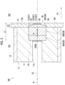
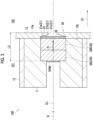
collimator 20 is not limited to the above-described embodiment. For example, acollimator 20 shown inFigs. 4A and 4B may be employed. As shown inFig. 4A , thecollimator 20 includes an innerperipheral surface 21a of thewall part 13 and aprotrusion part 40. Theprotrusion part 40 protrudes from thewall surface 13a of thewall part 13. Theprotrusion part 40 has a tubular structure having a truncated conical shape. Theprotrusion part 40 includes anupstream end portion 40c in the irradiating direction D1 and adownstream end portion 40d. Theupstream end portion 40c is attached to thewall surface 13a in a state where theupstream end portion 40c is in contact with thewall surface 13a of thewall part 13. A diameter of an innerperipheral surface 40a is the same as the diameter of the innerperipheral surface 21a of thewall part 13. The innerperipheral surface 40a and an outerperipheral surface 40b are reduced in diameter toward theend portion 40d from theend portion 40c. - The gamma
ray blocking member 26 is disposed on a side facing the patient 50 in thehole portion 21 of theprotrusion part 40. The gammaray blocking member 26 is disposed at a position of thedownstream end portion 40d of theprotrusion part 40. Thelayer 39D of thedeceleration member 39 is provided in thehole portion 21 of theprotrusion part 40. Thelayer 39D of thedeceleration member 39 extends from the position of theupstream end portion 40c of theprotrusion part 40 to the position of the gammaray blocking member 26. Thedeceleration member 39 is disposed in thehole portion 21 of theprotrusion part 40 over a range of a half or more of theprotrusion part 40 in the irradiating direction D1. - The
protrusion part 40 is detachable from thewall surface 13a. Thedownstream end portion 40c of theprotrusion part 40 in the irradiating direction D1 can be detached from thewall surface 13a of thewall part 13. In this case, as shown inFig. 4B , thelayer 39D of thedeceleration member 39 and the gammaray blocking member 26 in thehole portion 21 of theprotrusion part 40 can also be detached from thewall part 13 together with theprotrusion part 40. - The
protrusion part 40 attached to thewall part 13 is replaceable in accordance with the amount of thedeceleration member 39 to be required. For example, theprotrusion part 40 shown inFigs. 4A and 4B may be changed to aprotrusion part 40 shown inFig. 5A or aprotrusion part 40 shown inFig. 5B . Theprotrusion part 40 shown inFig. 5A includes alayer 39E thinner than thelayer 39D of thedeceleration member 39 of theprotrusion part 40 shown inFig. 4B . Thelayer 39E is disposed at a position separated to a position spaced downstream from theend portion 40c of theprotrusion part 40 in the irradiating direction D1. In this way, thedeceleration member 39 may be disposed in thehole portion 21 of theprotrusion part 40 over a range of a third or more of theprotrusion part 40 in the irradiating direction D1. Theprotrusion part 40 shown inFig. 5B does not include thedeceleration member 39. - As described above, the
collimator 20 may include theprotrusion part 40 protruding from thewall surface 13a and thedeceleration member 39 may be provided in thehole portion 21 of theprotrusion part 40. Since thedeceleration member 39 can be disposed even at a position closer to the patient 50 than thewall surface 13a in this case, a distance between thetarget 10 and the patient 50 can be shortened. - At least a part of the
protrusion part 40 may be detachable from thewall surface 13a. Accordingly, a part of thecollimator 20 can be easily detached from thewall surface 13a. That is, it is possible to easily adjust the size of thedeceleration member 39 that is disposed in thehole portion 21 of thecollimator 20. - The
deceleration member 39 may be disposed in thehole portion 21 of theprotrusion part 40 over a range of a half or more of theprotrusion part 40 in the irradiating direction D1. Accordingly, since thedeceleration member 39 that is disposed in thehole portion 21 of theprotrusion part 40 can be increased in size, a distance between thetarget 10 and the patient 50 can be shortened by that much. - The
wall surface 13a may extend perpendicular to the irradiating direction D1. In this case, theprotrusion part 40 has a simple configuration in which theprotrusion part 40 protrudes in the irradiating direction D1. -
- 1
- neutron capture therapy device
- 2
- accelerator
- 9
- beam duct (transport path)
- 10
- target
- 13a
- wall surface
- 20
- collimator
- 21
- hole portion
- 26
- gamma ray blocking member
- 39
- deceleration member
- 40
- protrusion part
Claims (8)
- A neutron capture therapy device comprising:an accelerator that generates a particle beam;a target that generates a neutron ray by reacting with the particle beam;a collimator that includes a hole portion penetrating in an irradiating direction of the neutron ray and forms an irradiation field of the neutron ray generated from the target; anda deceleration member that decelerates the neutron ray generated from the target,wherein a part of the deceleration member is disposed in the hole portion of the collimator.
- The neutron capture therapy device according to claim 1,
wherein at least a part of the collimator is detachable. - The neutron capture therapy device according to claim 1,wherein the collimator includes a protrusion part protruding from a wall surface, andthe deceleration member is provided in the hole portion of the protrusion part.
- The neutron capture therapy device according to claim 3,
wherein at least a part of the protrusion part is detachable from the wall surface. - The neutron capture therapy device according to claim 3,
wherein the deceleration member is disposed in the hole portion of the protrusion part over a range of a half or more of the protrusion part in the irradiating direction. - The neutron capture therapy device according to claim 3,
wherein the wall surface extends perpendicular to the irradiating direction. - The neutron capture therapy device according to claim 1,
wherein a gamma ray blocking member is disposed on a side facing an irradiation target in the hole portion of the collimator. - A collimator that forms an irradiation field of a neutron ray, the collimator comprising:a hole portion that penetrates in an irradiating direction of the neutron ray,wherein a deceleration member that decelerates the neutron ray is disposed in the hole portion.
Applications Claiming Priority (2)
| Application Number | Priority Date | Filing Date | Title |
|---|---|---|---|
| JP2022053834 | 2022-03-29 | ||
| PCT/JP2023/012539 WO2023190523A1 (en) | 2022-03-29 | 2023-03-28 | Neutron capture therapy device and collimator |
Publications (2)
| Publication Number | Publication Date |
|---|---|
| EP4501399A1 true EP4501399A1 (en) | 2025-02-05 |
| EP4501399A4 EP4501399A4 (en) | 2025-06-11 |
Family
ID=88202579
Family Applications (1)
| Application Number | Title | Priority Date | Filing Date |
|---|---|---|---|
| EP23780532.0A Pending EP4501399A4 (en) | 2022-03-29 | 2023-03-28 | Neutron capture therapy device and collimator |
Country Status (5)
| Country | Link |
|---|---|
| US (1) | US20250018225A1 (en) |
| EP (1) | EP4501399A4 (en) |
| JP (1) | JPWO2023190523A1 (en) |
| CN (1) | CN119095648A (en) |
| WO (1) | WO2023190523A1 (en) |
Family Cites Families (3)
| Publication number | Priority date | Publication date | Assignee | Title |
|---|---|---|---|---|
| JP6935878B2 (en) * | 2017-03-27 | 2021-09-15 | 株式会社八神製作所 | Neutron deceleration irradiation device and extended collimator |
| RU2734955C1 (en) * | 2017-06-05 | 2020-10-26 | Нойборон Медтех Лтд. | Beam forming unit for neutron capturing therapy |
| JP7287800B2 (en) | 2019-03-11 | 2023-06-06 | 住友重機械工業株式会社 | Neutron capture therapy system |
-
2023
- 2023-03-28 EP EP23780532.0A patent/EP4501399A4/en active Pending
- 2023-03-28 JP JP2024512570A patent/JPWO2023190523A1/ja active Pending
- 2023-03-28 WO PCT/JP2023/012539 patent/WO2023190523A1/en not_active Ceased
- 2023-03-28 CN CN202380031295.6A patent/CN119095648A/en active Pending
-
2024
- 2024-09-26 US US18/898,578 patent/US20250018225A1/en active Pending
Also Published As
| Publication number | Publication date |
|---|---|
| JPWO2023190523A1 (en) | 2023-10-05 |
| EP4501399A4 (en) | 2025-06-11 |
| WO2023190523A1 (en) | 2023-10-05 |
| US20250018225A1 (en) | 2025-01-16 |
| CN119095648A (en) | 2024-12-06 |
Similar Documents
| Publication | Publication Date | Title |
|---|---|---|
| US10773104B2 (en) | Neutron capture therapy system | |
| JP2023078466A (en) | Neutron capture therapy system | |
| JP5490651B2 (en) | Neutron beam irradiation system | |
| RU2734955C1 (en) | Beam forming unit for neutron capturing therapy | |
| RU2707651C1 (en) | Apparatus for neutron therapy | |
| JP6261919B2 (en) | Neutron irradiation equipment | |
| JP6732244B2 (en) | Neutron moderation irradiation device | |
| WO2013003343A2 (en) | Neutron source for neutron capture therapy | |
| CN206535011U (en) | Neutron capture treatment system | |
| KR101839369B1 (en) | Boron Neutron Capture Therapy System | |
| WO2017146205A1 (en) | Neutron capture therapy device, and target for neutron capture therapy | |
| TWI771964B (en) | Charged particle beam irradiation device | |
| JP5850362B2 (en) | Neutron beam irradiation apparatus and method of operating the apparatus | |
| TW201912200A (en) | Neutron capture therapy system | |
| JP7072196B1 (en) | Low-energy charged particle beam transport system and charged particle beam transport method in BNCT | |
| CN107998517A (en) | Neutron capture treatment system | |
| US20250018225A1 (en) | Neutron capture therapy device and collimator | |
| KR102274044B1 (en) | Collimator for Considering the patient positioning | |
| JP6266399B2 (en) | Neutron capture therapy device | |
| TWI811649B (en) | Charged Particle Irradiation Control Device | |
| JP2016134281A (en) | Negative ion source device | |
| US20250312620A1 (en) | Neutron capture therapy apparatus | |
| JP7821162B2 (en) | Neutron beam generator and neutron beam therapy equipment | |
| CN222693888U (en) | Neutron production target catheter and neutron capture therapy device | |
| JP7082914B2 (en) | How to install a collimator for neutron capture therapy and a neutron beam collimator |
Legal Events
| Date | Code | Title | Description |
|---|---|---|---|
| STAA | Information on the status of an ep patent application or granted ep patent |
Free format text: STATUS: THE INTERNATIONAL PUBLICATION HAS BEEN MADE |
|
| PUAI | Public reference made under article 153(3) epc to a published international application that has entered the european phase |
Free format text: ORIGINAL CODE: 0009012 |
|
| STAA | Information on the status of an ep patent application or granted ep patent |
Free format text: STATUS: REQUEST FOR EXAMINATION WAS MADE |
|
| 17P | Request for examination filed |
Effective date: 20241001 |
|
| AK | Designated contracting states |
Kind code of ref document: A1 Designated state(s): AL AT BE BG CH CY CZ DE DK EE ES FI FR GB GR HR HU IE IS IT LI LT LU LV MC ME MK MT NL NO PL PT RO RS SE SI SK SM TR |
|
| STAA | Information on the status of an ep patent application or granted ep patent |
Free format text: STATUS: EXAMINATION IS IN PROGRESS |
|
| A4 | Supplementary search report drawn up and despatched |
Effective date: 20250513 |
|
| RIC1 | Information provided on ipc code assigned before grant |
Ipc: A61N 5/10 20060101AFI20250507BHEP |
|
| 17Q | First examination report despatched |
Effective date: 20250523 |
|
| DAV | Request for validation of the european patent (deleted) | ||
| DAX | Request for extension of the european patent (deleted) |