EP4501243A1 - Zweiebenen-ultraschallbildplanungsverfahren und -vorrichtung - Google Patents
Zweiebenen-ultraschallbildplanungsverfahren und -vorrichtung Download PDFInfo
- Publication number
- EP4501243A1 EP4501243A1 EP23774001.4A EP23774001A EP4501243A1 EP 4501243 A1 EP4501243 A1 EP 4501243A1 EP 23774001 A EP23774001 A EP 23774001A EP 4501243 A1 EP4501243 A1 EP 4501243A1
- Authority
- EP
- European Patent Office
- Prior art keywords
- image
- cross
- coordinate system
- sagittal
- conversion matrix
- Prior art date
- Legal status (The legal status is an assumption and is not a legal conclusion. Google has not performed a legal analysis and makes no representation as to the accuracy of the status listed.)
- Pending
Links
Images


Classifications
-
- A—HUMAN NECESSITIES
- A61—MEDICAL OR VETERINARY SCIENCE; HYGIENE
- A61B—DIAGNOSIS; SURGERY; IDENTIFICATION
- A61B34/00—Computer-aided surgery; Manipulators or robots specially adapted for use in surgery
- A61B34/10—Computer-aided planning, simulation or modelling of surgical operations
-
- A—HUMAN NECESSITIES
- A61—MEDICAL OR VETERINARY SCIENCE; HYGIENE
- A61B—DIAGNOSIS; SURGERY; IDENTIFICATION
- A61B8/00—Diagnosis using ultrasonic, sonic or infrasonic waves
- A61B8/52—Devices using data or image processing specially adapted for diagnosis using ultrasonic, sonic or infrasonic waves
- A61B8/5215—Devices using data or image processing specially adapted for diagnosis using ultrasonic, sonic or infrasonic waves involving processing of medical diagnostic data
-
- A—HUMAN NECESSITIES
- A61—MEDICAL OR VETERINARY SCIENCE; HYGIENE
- A61B—DIAGNOSIS; SURGERY; IDENTIFICATION
- A61B34/00—Computer-aided surgery; Manipulators or robots specially adapted for use in surgery
- A61B34/20—Surgical navigation systems; Devices for tracking or guiding surgical instruments, e.g. for frameless stereotaxis
-
- A—HUMAN NECESSITIES
- A61—MEDICAL OR VETERINARY SCIENCE; HYGIENE
- A61B—DIAGNOSIS; SURGERY; IDENTIFICATION
- A61B8/00—Diagnosis using ultrasonic, sonic or infrasonic waves
- A61B8/08—Clinical applications
- A61B8/0833—Clinical applications involving detecting or locating foreign bodies or organic structures
- A61B8/0841—Clinical applications involving detecting or locating foreign bodies or organic structures for locating instruments
-
- A—HUMAN NECESSITIES
- A61—MEDICAL OR VETERINARY SCIENCE; HYGIENE
- A61B—DIAGNOSIS; SURGERY; IDENTIFICATION
- A61B8/00—Diagnosis using ultrasonic, sonic or infrasonic waves
- A61B8/08—Clinical applications
- A61B8/0833—Clinical applications involving detecting or locating foreign bodies or organic structures
- A61B8/085—Clinical applications involving detecting or locating foreign bodies or organic structures for locating body or organic structures, e.g. tumours, calculi, blood vessels, nodules
-
- A—HUMAN NECESSITIES
- A61—MEDICAL OR VETERINARY SCIENCE; HYGIENE
- A61B—DIAGNOSIS; SURGERY; IDENTIFICATION
- A61B8/00—Diagnosis using ultrasonic, sonic or infrasonic waves
- A61B8/12—Diagnosis using ultrasonic, sonic or infrasonic waves in body cavities or body tracts, e.g. by using catheters
-
- A—HUMAN NECESSITIES
- A61—MEDICAL OR VETERINARY SCIENCE; HYGIENE
- A61B—DIAGNOSIS; SURGERY; IDENTIFICATION
- A61B8/00—Diagnosis using ultrasonic, sonic or infrasonic waves
- A61B8/42—Details of probe positioning or probe attachment to the patient
- A61B8/4245—Details of probe positioning or probe attachment to the patient involving determining the position of the probe, e.g. with respect to an external reference frame or to the patient
- A61B8/4254—Details of probe positioning or probe attachment to the patient involving determining the position of the probe, e.g. with respect to an external reference frame or to the patient using sensors mounted on the probe
-
- A—HUMAN NECESSITIES
- A61—MEDICAL OR VETERINARY SCIENCE; HYGIENE
- A61B—DIAGNOSIS; SURGERY; IDENTIFICATION
- A61B8/00—Diagnosis using ultrasonic, sonic or infrasonic waves
- A61B8/44—Constructional features of the ultrasonic, sonic or infrasonic diagnostic device
- A61B8/4444—Constructional features of the ultrasonic, sonic or infrasonic diagnostic device related to the probe
-
- A—HUMAN NECESSITIES
- A61—MEDICAL OR VETERINARY SCIENCE; HYGIENE
- A61B—DIAGNOSIS; SURGERY; IDENTIFICATION
- A61B8/00—Diagnosis using ultrasonic, sonic or infrasonic waves
- A61B8/44—Constructional features of the ultrasonic, sonic or infrasonic diagnostic device
- A61B8/4477—Constructional features of the ultrasonic, sonic or infrasonic diagnostic device using several separate ultrasound transducers or probes
-
- A—HUMAN NECESSITIES
- A61—MEDICAL OR VETERINARY SCIENCE; HYGIENE
- A61B—DIAGNOSIS; SURGERY; IDENTIFICATION
- A61B8/00—Diagnosis using ultrasonic, sonic or infrasonic waves
- A61B8/44—Constructional features of the ultrasonic, sonic or infrasonic diagnostic device
- A61B8/4483—Constructional features of the ultrasonic, sonic or infrasonic diagnostic device characterised by features of the ultrasound transducer
- A61B8/4488—Constructional features of the ultrasonic, sonic or infrasonic diagnostic device characterised by features of the ultrasound transducer the transducer being a phased array
-
- A—HUMAN NECESSITIES
- A61—MEDICAL OR VETERINARY SCIENCE; HYGIENE
- A61B—DIAGNOSIS; SURGERY; IDENTIFICATION
- A61B8/00—Diagnosis using ultrasonic, sonic or infrasonic waves
- A61B8/46—Ultrasonic, sonic or infrasonic diagnostic devices with special arrangements for interfacing with the operator or the patient
- A61B8/461—Displaying means of special interest
- A61B8/463—Displaying means of special interest characterised by displaying multiple images or images and diagnostic data on one display
-
- A—HUMAN NECESSITIES
- A61—MEDICAL OR VETERINARY SCIENCE; HYGIENE
- A61B—DIAGNOSIS; SURGERY; IDENTIFICATION
- A61B8/00—Diagnosis using ultrasonic, sonic or infrasonic waves
- A61B8/54—Control of the diagnostic device
-
- A—HUMAN NECESSITIES
- A61—MEDICAL OR VETERINARY SCIENCE; HYGIENE
- A61B—DIAGNOSIS; SURGERY; IDENTIFICATION
- A61B8/00—Diagnosis using ultrasonic, sonic or infrasonic waves
- A61B8/58—Testing, adjusting or calibrating the diagnostic device
-
- A—HUMAN NECESSITIES
- A61—MEDICAL OR VETERINARY SCIENCE; HYGIENE
- A61B—DIAGNOSIS; SURGERY; IDENTIFICATION
- A61B34/00—Computer-aided surgery; Manipulators or robots specially adapted for use in surgery
- A61B34/10—Computer-aided planning, simulation or modelling of surgical operations
- A61B2034/107—Visualisation of planned trajectories or target regions
-
- A—HUMAN NECESSITIES
- A61—MEDICAL OR VETERINARY SCIENCE; HYGIENE
- A61B—DIAGNOSIS; SURGERY; IDENTIFICATION
- A61B34/00—Computer-aided surgery; Manipulators or robots specially adapted for use in surgery
- A61B34/20—Surgical navigation systems; Devices for tracking or guiding surgical instruments, e.g. for frameless stereotaxis
- A61B2034/2046—Tracking techniques
- A61B2034/2063—Acoustic tracking systems, e.g. using ultrasound
Definitions
- the present application relates to the technical field of medical electronics, and in particular to a biplanar ultrasound image planning method and apparatus.
- a biplanar ultrasonic probe can be commonly used in urology and anorectal surgery.
- Transrectal ultrasound (TRUS) examination includes a high-resolution two-dimensional image display technology and a color Doppler technology.
- Transrectal biplanar probe examination has high ultrasonic frequency and can obtain high-resolution images in two directions, thereby clearly displaying the prostate blood flow distribution characteristic and echo intensity.
- a doctor needs to obtain ultrasound images in two different directions (cross section and sagittal plane) through a transrectal biplanar ultrasonic probe during surgery.
- the doctor can perform spatial position identification and manual labeling by respectively reading the cross-sectional and sagittal images, or manual input parameters, and information input by the doctor is converted into cutting path planning during surgery.
- the doctor needs to repeatedly move the ultrasonic probe to observe the target position when manually using the biplanar ultrasound.
- the spatial position relationship between two planes is determined generally by identifying a structural key area in the image, which is time-consuming, laborious and poor in accuracy and stability.
- the present application provides a biplanar ultrasound image planning method and apparatus, which solve the problem of large path errors in existing methods, and are particularly suitable for surgical scenarios such as urological intervention, particle implantation therapy and tissue resection.
- the marker is a biplanar ultrasonic probe.
- the method further includes: the marker is either a convex array probe for photographing the cross-sectional image or a linear array probe for photographing the sagittal image.
- the marker is either a convex array probe for photographing the cross-sectional image or a linear array probe for photographing the sagittal image.
- the step of displaying in the other coordinate system further includes:
- the step of displaying in the other coordinate system further includes:
- calibrating the position relationship between the marker and the cross-sectional image by a spatial correction method to obtain the first conversion matrix specifically includes:
- the position relationship between the marker and the sagittal image is calibrated by a spatial correction method to obtain the second conversion matrix, or inverse matrix operation is performed on the first conversion matrix to obtain the second conversion matrix.
- the method further includes: converting a planned position in the coordinate system of the cross-sectional image or the coordinate system of the sagittal image into a motion or energy execution parameter, the motion or energy execution parameter being a parameter for controlling the motion and energy of an execution mechanism.
- the step of displaying the target position and the planned position in the cross-sectional image in a follow-up manner according to the target position and the planned position in the sagittal image further includes:
- the step of displaying the target position and the planned position in the cross-sectional image in a follow-up manner according to the target position and the planned position in the sagittal image further includes:
- the step of displaying the target position and the planned position in the sagittal image in a follow-up manner according to the target position and the planned position in the cross-sectional image further includes:
- the step of displaying the target position and the planned position in the sagittal image in a follow-up manner according to the target position and the planned position in the cross-sectional image further includes:
- the method used for positioning needle correction is a spherical fitting method.
- the execution mechanism is a motion motor and or an energy generation apparatus.
- the execution mechanism is a motion motor and or an energy generation apparatus of a laser knife, an ultrasound knife, a water jet cutter and or an electrotome.
- biplanar ultrasound image planning apparatus which is an apparatus for planning a biplanar ultrasound image photographed by an ultrasonic probe, uses the method according to any one of claims 1 to 15, and includes: an ultrasonic imaging module, a control module and a display module, where
- a doctor needs to repeatedly move the ultrasonic probe to observe the target position when manually using the biplanar ultrasound.
- the spatial position relationship between two planes is determined generally by identifying a structural key area in the image, which is time-consuming, laborious and poor in accuracy and stability.
- an existing automatic water jet cutter planning method is rough in adjusting the corresponding movement of the boundary shape change of human organs, and a specific implementable method is not provided to establish an accurate corresponding relationship between the sagittal and cross-sectional images of the biplanar ultrasonic probe.
- an operator needs to manually acquire limited ultrasound image information.
- the whole organic is divided into several limited sections (such as three to four sections) based on the knowledge of human anatomy for parameter setting.
- the boundary change of the organ in the middle of each section only can be fitted through interpolation simulation.
- a specific method is not provided to reduce the fitting interval, thereby having an obvious error with the real organ boundary change curve.
- the present application has the following innovation points. 1.
- the present application provides a method for determining the conversion between a biplanar ultrasound image and the physical position of an ultrasonic probe, which can acquire a relationship between two planar ultrasound images and the target position and is accurate in positioning and convenient to use.
- the present application provides a method for planning follow-up acquisition and follow-up display of a biplanar ultrasound image.
- An ultrasonic probe adapter drives a dual-array ultrasonic probe to move automatically, which can be used to scan the whole organ and acquire continuous images of each cross section of the organ to accurately correspond to each position of the sagittal plane to achieve fine surgical planning, thereby achieving high-precision tissue ablation.
- FIG. 1(a) is a method flowchart of a method embodiment of the present application.
- FIG. 1(b) is a schematic diagram of a coordinate system of a probe of a method embodiment of the present application.
- FIG. 1(c) is a schematic diagram of a spatial correction principle of a method embodiment of the present application.
- FIG. 1(d) is a schematic diagram of a positioning needle correction principle of a method embodiment of the present application.
- FIG. 1(e) is a schematic diagram of a coordinate system of a positioning needle of a method embodiment of the present application.
- FIG. 1(b) , FIG. 1(c) and FIG. 1(e) provide the description of each coordinate system of the embodiments of the present application.
- the ultrasonic probe 11 may be a biplanar ultrasonic probe, or may be a convex array probe or linear array probe.
- a positioning and tracking sensor 14 is arranged in the ultrasonic probe 11, and a coordinate system established with the centroid of the positioning and tracking sensor as the origin is the coordinate system of the ultrasonic probe.
- the ultrasonic probe in FIG. 1(b) and FIG. 1(c) is the biplanar ultrasonic probe
- the coordinate system of the ultrasonic probe is the coordinate system of the biplanar ultrasonic probe, that is, a coordinate system of a marker in the embodiments of the present application. If the ultrasonic probe in FIG. 1(b) and FIG.
- the coordinate system of the ultrasonic probe is the coordinate system of the convex array probe or linear array probe, corresponding to the coordinate system of the marker or the coordinate system of the second ultrasonic probe in the embodiment in FIG. 5 of the present application.
- the marker in the present application is not limited to the biplanar ultrasonic probe, the convex array probe and the linear array probe, and may further be a marked object imaged in the probe.
- the marked probe includes a plurality of marking points that can be imaged in the ultrasonic probe and have the known relative spatial position relationship on the marked object. That is, the marker in the present application is not limited to the biplanar ultrasonic probe, the convex array probe and the linear array probe, and may further be other objects containing features.
- an image coordinate system may be established at the position where the ultrasonic probe is connected to the human tissue.
- the coordinate system of the cross-sectional image is established in the Step 101, and the coordinate system of the sagittal image is established in the Step 102.
- a positioning needle point 13 is a needle point of a positioning needle 12
- a needle body part of the positioning needle is provided with a positioning and tracking sensor
- a coordinate system established with the positioning needle point as the origin is a coordinate system of the positioning needle point
- a coordinate system established with the centroid of the positioning and tracking sensor in the needle body of the positioning needle as the origin is a coordinate system of the positioning needle.
- each coordinate system has a conversion relationship.
- the image coordinate system (the coordinate system of the cross-sectional image or the coordinate system of the sagittal image) can be converted into the coordinate system of the ultrasonic probe, the image coordinate system can be converted into the coordinate system of the positioning needle point, the coordinate system of the positioning needle point can be converted into the coordinate system of the positioning needle, and the coordinate system of the positioning needle can be converted into the coordinate system of the ultrasonic probe.
- each coordinate system in the present application may be an XYZ rectangular coordinate system, or may be other coordinate systems, without special explanation herein.
- a biplanar ultrasound image planning method specifically includes the following Steps 101-103.
- Step 101 a position relationship between a marker and a cross-sectional image is calibrated to obtain a first conversion matrix, where the first conversion matrix is a matrix converted from a coordinate system of the cross-sectional image to a coordinate system of the marker.
- the marker in the Steps 101-103 is the biplanar ultrasonic probe and can generate the cross-sectional image and a sagittal image.
- a coordinate system established with the centroid of a positioning and tracking sensor as the origin is the coordinate system of the marker, also referred to as the coordinate system of the biplanar ultrasonic probe.
- the cross-sectional image is calibrated by the positioning and tracking sensor in the biplanar ultrasonic probe to determine the first conversion matrix T Aim2p .
- the cross-sectional image may be calibrated by a spatial correction algorithm, which specifically includes the following Steps101A-101E.
- Step 101A a fifth conversion matrix T As2st converted from a coordinate system of a positioning needle to a coordinate system of a positioning needle point is established through positioning needle correction.
- a positioning needle correction principle is provided, the positioning needle point can rotate around a fixed position point, and the positioning and tracking sensor is mounted on the positioning needle.
- the coordinates of the fixed position point in a world coordinate system are (X 0 , Y 0 , Z 0 ), the coordinates of the start position during rotation of the positioning needle are (X 1 , Y 1 , Z 1 ), the coordinates of the end position during rotation of the positioning needle are (X 2 , Y 2 , Z 2 ), and in the rotation process, the center of sphere is T 0 and the radius is R 0 . (0, 0, 0) is the origin of the world coordinate system and is determined by a camera of the positioning needle.
- Step 101AB coordinate transformation is performed on the position of the coordinate system of the positioning needle point.
- Step 101AC PP_M and PP_R are solved by the least square method.
- the optimal solution of xi is solved by the least square method to obtain PP_M and PP_R.
- Step 101AD a conversion matrix T s2st converted from the coordinate system of the positioning needle to the coordinate system of the positioning needle point is calculated.
- Step 101B a sixth conversion matrix T Ast2p converted from the coordinate system of the positioning needle to the coordinate system of the biplanar ultrasonic probe is obtained through a positioning and tracking system.
- the positioning and tracking system is configured to obtain the sixth conversion matrix through the positioning and tracking sensor on the positioning needle and the positioning and tracking sensor on the biplanar ultrasonic probe.
- the positioning and tracking system may be a multi-target optical camera, or may be systems for positioning and tracking the positions of the positioning needle and the biplanar ultrasonic probe.
- Step 101C a seventh conversion matrix T Ast2p converted from the coordinate system of the positioning needle point to the coordinate system of the biplanar ultrasonic probe through the fifth conversion matrix and the sixth conversion matrix.
- Step 101D an eighth conversion matrix T Ast2im converted from the coordinate system of the positioning needle point to the coordinate system of the cross-sectional image is calculated according to a position relationship of the positioning needle in the cross-sectional image.
- T Ast2im ⁇ T Aim2p T Ast2p
- Step 102 a position relationship between the biplanar ultrasonic probe and the sagittal image is calibrated to obtain a second conversion matrix, where the second conversion matrix is a matrix converted from the coordinate system of the sagittal image to the coordinate system of the biplanar ultrasonic probe.
- the position relationship between the biplanar ultrasonic probe and the sagittal image can be calibrated by a spatial correction method to obtain the second conversion matrix T Bim2p .
- the method for calculating the second conversion matrix is the same as the method for calculating the first conversion matrix in the Step 101, specifically including the following Steps 102A-102E.
- the ninth conversion matrix and the fifth conversion matrix may be the same matrix or different matrices, depending on the placing position and the placing angle of the positioning needle point.
- Step 102B a tenth conversion matrix T Bst2p converted from the coordinate system of the positioning needle to the coordinate system of the biplanar ultrasonic probe is obtained through the positioning and tracking system.
- Step 102D a twelfth conversion matrix T Bst2im converted from the coordinate system of the positioning needle point to the coordinate system of the sagittal image is calculated according to a position relationship of the positioning needle in the sagittal image.
- Step 102E the second conversion matrix T Bim2p is calculated according to the eleventh conversion matrix and the twelfth conversion matrix.
- T Bim2p T Bst2im ⁇ 1 ⁇ T Bst2p
- Step 103 a third conversion matrix and or a fourth conversion matrix are/is calculated by a matrix conversion relationship, and a target position displayed in any one of the coordinate system of the cross-sectional image and the coordinate system of the sagittal image is displayed in the other coordinate system in a follow-up manner.
- the third conversion matrix is a matrix converted from the coordinate system of the cross-sectional image to the coordinate system of the sagittal image
- the fourth matrix is a matrix converted from the coordinate system of the sagittal image to the coordinate system of the cross-sectional image.
- the target position may be displayed in the coordinate system of the cross-sectional image, and the target position of the target may be displayed in the coordinate system of the sagittal image in a follow-up manner, or the target position may be displayed in the coordinate system of the sagittal image, and the target position of the target may be displayed in the coordinate system of the cross-sectional image in a follow-up manner.
- the planned position displayed in any one of the coordinate system of the cross-sectional image and the coordinate system of the sagittal image is displayed in the other coordinate system in a follow-up manner.
- the target position refers to the position of a target outline required to be displayed
- the planned position refers to the outline position of a planned trajectory
- boundary planning is performed according to the target position to obtain the planned position.
- the embodiments of the present application provide a biplanar ultrasonic planning method.
- a position relationship conversion matrix of the ultrasonic biplanar probe and the image is established through image calibration, and the flow can be performed on a device once before clinical use without changing the hardware structure and the connection mode.
- the method can be used for a transrectal biplanar ultrasonic probe for prostate surgery navigation.
- the embodiments of the present application can be used for image display scenarios. For example, a position relationship between two planar ultrasonic images and the actual tissue organ can be established in the surgery scenario using biplanar ultrasound, and images of two planes of the ultrasonic probe can be displayed accurately in a follow-up manner for diagnosing or cooperating with other surgical instruments in the images to arrive at the preoperative planned or intraoperative target position of the doctor.
- FIG. 2 is a flowchart of a method embodiment of the present application including image follow-up planning, which can be used for a surgical process to achieve the image follow-up planning of the cross-sectional image.
- a biplanar ultrasonic image planning method specifically includes the following Steps 101-102 and 104-106.
- a position relationship between the ultrasonic physical position and the image is established first by acquiring a biplanar ultrasonic image in real time, that is, an index relationship table in the flow. Then in the surgical planning, the cross-sectional image will be acquired or displayed in a follow-up manner according to the target position in the sagittal image and the target planning.
- Step 101 a position relationship between the marker and the cross-sectional image is calibrated to obtain a first conversion matrix.
- Step 102 a position relationship between the marker and the sagittal image is calibrated to obtain a second conversion matrix.
- Step 104 a third conversion matrix and or a fourth conversion matrix are/is calculated by a matrix conversion matrix.
- Step 105 a first index relationship table or a second index relationship table is established in the movement process of the ultrasonic probe, where the first index relationship table is an index relationship table of the physical position of the ultrasonic probe and the position of the cross section, and the second index relationship table is an index relationship table of storage position information of the cross-sectional image and the position of the cross section.
- the physical position of the ultrasonic probe refers to the actual physical position of the ultrasonic probe
- the position of the cross section refers to a coordinate set of cross-section image positions acquired in real time
- the storage position information of the cross-sectional image refers to a prestored cross-sectional image.
- the ultrasonic probe moves from the physical position M1 of the ultrasonic probe to Mn under the control of an ultrasonic adapter, and in the movement process, the ultrasonic image of the cross section is acquired in real time according to a fixed step length, that is, the positions S1 to Sn of the cross section.
- Step 105 a first index relationship table: [ ⁇ S1: M1, ..., Sn: Mn ⁇ ] is established, where the position of the cross section is in one-to-one correspondence with the physical position of the ultrasonic probe.
- a second index relationship table: [ ⁇ S1: ImgA1, ..., Sn: ImgAn ⁇ ] is established, where ImgA1 to ImgAn represent the storage position information of the cross-sectional image, which is in one-to-one correspondence with the position of the cross section.
- the position of the cross section and the position of the sagittal plane acquired at a certain moment represent images acquired by the biplanar ultrasonic probe at the same moment.
- the physical position of the cross-sectional image (or the position of the cross section) and the physical position of the sagittal image (or the position of the sagittal plane) are related to the mounting positions of the two probes, and the two positions are converted by the conversion matrix T Aim2Bim or T Bim2Aim .
- Step 106 the target position and planned position in the cross-sectional image are displayed in a follow-up manner according to the target position and planned position in the sagittal image and by using the first index relationship table or the second index relationship table.
- the cross-sectional image will be displayed in a follow-up manner according to the target position and planned position in the sagittal image, which is specifically implemented by one of the following two methods.
- Method 1 the target position and planned position in the cross-sectional image can be displayed in a follow-up manner according to the target position and planned position in the sagittal image and by using the first index relationship table in the real-time surgical planning, which specifically includes the following Steps 106A-106D.
- Step 106A a pixel point position is calculated, a target position in the coordinate system of the sagittal image is acquired, and a target position in the coordinate system of the cross-sectional image is calculated according to the third conversion matrix.
- the coordinates of the target position in the coordinate system of the sagittal image are ti
- the coordinates of the target position in the coordinate system of the cross-sectional image are si
- si T Bim2Aim ⁇ ti.
- Step 106B in the first index relationship table, the closest first cross-sectional position and second cross-sectional position are obtained by looking up the table, the coordinates Mx1 of the physical position of a first cross-sectional probe and the coordinates Mx2 of the physical position of a second cross-sectional probe are correspondingly obtained, and the coordinates Mx of the physical position of a target cross-sectional probe are obtained through interpolation, where the first and second cross sections are two cross sections closest to a cross section Sx corresponding to a target position si, and the cross-sectional positions corresponding to the two cross sections are respectively Sx1 and Sx2; and si is the target position in the coordinate system of the cross-sectional image, Sx is the corresponding cross-section position of si in the coordinate system of the cross-sectional image, and Sx1 and Sx2 are respectively the first and second cross-sectional positions.
- first cross-sectional position and the second cross-sectional position refer to a position coordinate set of cross-sectional images.
- Step 106C the ultrasonic probe is moved to the coordinates of the physical position of the target cross-sectional probe to obtain the cross-sectional image and the target position of the image.
- the ultrasonic cross-sectional real-time image displayed at this time is the cross-sectional image corresponding to the target position of the sagittal plane.
- the coordinates of the target position in the cross-sectional image can be obtained according to the coordinates si of the target position.
- Step 106D the planned position in the sagittal image can be constructed in the real-time surgical planning to correspondingly obtain the planned position in the cross-sectional image.
- Step 106D after a planning curve is constructed on the sagittal plane in the real-time surgical planning, the system displays the cross-sectional image at all the planned position points on the sagittal plane in a follow-up manner and displays the position of the planned position on the cross-sectional image.
- Method 2 the target position and planned position in the cross-sectional image can be displayed in a follow-up manner according to the target position and planned position in the sagittal image by using the second index relationship table in the real-time surgical planning, which specifically includes the following Steps 106E-106H.
- the Step 106E is the same as the Step 106A.
- Step 106F in the second index relationship table, the closest first cross-sectional position and second cross-sectional position are obtained by looking up the table, and the storage positions of the first and second cross-sectional images are correspondingly obtained, where the first and second cross sections are two cross sections closest to a cross section Sx corresponding to a target position si, and the cross-sectional positions corresponding to the two cross sections are respectively Sx1 and Sx2; and si is the target position in the coordinate system of the cross-sectional image, Sx is the corresponding cross-section position of si in the coordinate system of the cross-sectional image, and Sx1 and Sx2 are respectively the first and second cross-sectional positions.
- Step 106G a cross section closest to Sx is selected from the first and second cross sections, and the cross-sectional image and the target position in the image are displayed according to the storage position of the corresponding cross-sectional image.
- the cross section is a cross section in the first and second cross sections closest to Sx, and the coordinates of the target position in the cross-sectional image can be obtained according to the coordinates si of the target position.
- Step 106H the planned position in the sagittal image is constructed in the real-time surgical planning to correspondingly obtain the planned position in the cross-sectional image.
- the Step 106H is the same as the Step 106D.
- the ultrasonic probe is placed at the far point of a motion trajectory (relative to a device end), and the sagittal image range at this position can cover the required entire prostate tissue.
- This position is recorded as a motion zero point of an ultrasonic probe adapter.
- the ultrasonic probe should keep a fixed position at the zero point and provide a sagittal image for observation and monitoring in the surgical process.
- the ultrasonic probe adapter controls the ultrasonic probe to linearly move in a Z direction from the zero point position to a direction away from a human body, keeps the work of a convex array probe in the motion process and continuously acquires the cross-sectional image, and then returns to the zero point position after acquisition to enter a next planning step.
- the ultrasonic probe adapter has a position sensor, and the system records the Z-direction displacement of each cross-section image acquired by the sensor in the motion process.
- the ultrasonic adapter can be controlled according to the Step 106A to the Step 106D to move the ultrasonic probe to the target position to acquire and display a real-time ultrasonic cross-sectional image in a follow-up manner, or the acquired cross-sectional image can be displayed in a follow-up manner directly according to the position and according to the Step 106E to the Step 106H.
- the error between the Z-coordinate position of the cross-sectional image and the Z-coordinate position selected by planning is determined by an image sampling rate in the motion and acquisition position of the cross-sectional image.
- the embodiment described in the present application takes the ultrasonic-guided prostate tissue ablation scenario for the rectal cavity as an example.
- the system and control method of the present application can also be applied to other cavities (such as digestive tract, urinary tract, genital tract, nasal cavity, external auditory canal and canalis nasolacrimalis) and organs.
- FIG. 3 is another flowchart of a method embodiment of the present application including image follow-up planning, which can be used for a surgical process to achieve the image follow-up planning of the sagittal image.
- a biplanar ultrasonic image planning method specifically includes the following Steps 101, 102, 104 and 107-108.
- Step 101 a position relationship between the marker and the cross-sectional image is calibrated to obtain a first conversion matrix.
- Step 102 a position relationship between the marker and the sagittal image is calibrated to obtain a second conversion matrix.
- Step 104 a third conversion matrix and or a fourth conversion matrix are/is calculated by a matrix conversion matrix.
- Step 107 a third index relationship table or a fourth index relationship table is established in the movement process of the marker, where the third index relationship table is an index relationship table of the physical position of the marker and the position of the sagittal plane, and the fourth index relationship table is an index relationship table of the storage position information of the sagittal image and the position of the sagittal plane.
- the physical position of the ultrasonic probe refers to the actual physical position of the ultrasonic probe
- the position of the sagittal plane refers to a coordinate set of sagittal image positions acquired in real time
- the storage position information of the sagittal image refers to a prestored sagittal image.
- the ultrasonic probe moves from the physical position M1 of the ultrasonic probe to Mn under the control of an ultrasonic adapter, and in the movement process, the ultrasonic image of the sagittal plane is acquired in real time according to a fixed step length, that is, the positions T1 to Tn of the sagittal plane.
- a third index relationship table [ ⁇ T1: M1, ..., Tn: Mn ⁇ ] is established, where the position of the sagittal plane is in one-to-one correspondence with the physical position of the ultrasonic probe.
- a fourth index relationship table: [ ⁇ T1: ImgB1, ..., Tn: ImgBn ⁇ ] is established, where ImgB1 to ImgBn represent the storage position information of the sagittal image, which is in one-to-one correspondence with the position of the sagittal plane.
- the position of the cross section and the position of the sagittal plane acquired at a certain moment represent images acquired by the biplanar ultrasonic probe at the same moment.
- the physical position of the cross-sectional image (or the position of the cross section) and the physical position of the sagittal image (or the position of the sagittal plane) are related to the mounting positions of the two probes, and the two positions are converted by the conversion matrix T Aim2Bim or T Bim2Aim .
- Step 108 the target position and planned position in the sagittal image are displayed in a follow-up manner according to the target position and planned position in the cross-sectional image and by using the third index relationship table or the fourth index relationship table.
- Step 108 the sagittal image will be displayed in a follow-up manner according to the target position and planned position in the cross-sectional image, which is specifically implemented by one of the following two methods.
- Method 1 the target position and planned position in the sagittal image can be displayed in a follow-up manner according to the target position and planned position in the cross-sectional image and by using the third index relationship table in the real-time surgical planning, which specifically includes the following Steps 108A-108D.
- Step 108A a pixel point position is calculated, a target position in the coordinate system of the cross-sectional image is acquired, and a target position in the coordinate system of the sagittal image is calculated according to the fourth conversion matrix.
- the coordinates of the target position in the coordinate system of the cross-sectional image are si
- the coordinates of the target position in the coordinate system of the sagittal image are ti
- ti T Aim2Bim ⁇ si.
- Step 108B in the third index relationship table, a first sagittal position and a second sagittal position are obtained by looking up the table, the coordinates of the physical positions of the first and second sagittal probes are obtained correspondingly, and the coordinates of the physical position of a target sagittal probe are obtained through interpolation, where the first and second sagittal planes are two sagittal planes closest to the sagittal plane Tx corresponding to the target position ti, and Tx1 and Tx2 are the positions of the two sagittal planes; and ti is the target position in the coordinate system of the sagittal image, Tx is the position of the sagittal plane corresponding to ti, and Tx1 and Tx2 are respectively the first and second sagittal positions.
- Step 108C a first ultrasonic probe is moved to the coordinates of the physical position of the target sagittal probe to obtain the sagittal image and the target position in the image.
- the ultrasonic sagittal real-time image displayed at this time is the sagittal image corresponding to the target position of the cross section.
- the coordinates of the target position in the sagittal image can be obtained according to the coordinates ti of the target position.
- Step 108D the planned position can be constructed on the cross-sectional image in the real-time surgical planning to correspondingly obtain the planned position in the sagittal image.
- Step 108D after a planning curve is constructed on the cross section in the real-time surgical planning, the system displays the sagittal image at all the planned position points on the cross section in a follow-up manner and displays the position of the planned position on the sagittal image.
- Method 2 the target position and planned position in the sagittal image can be displayed in a follow-up manner according to the target position and planned position in the cross-sectional image by using the fourth index relationship table in the real-time surgical planning, which specifically includes the following Steps 108E-108H.
- Step 108E a pixel point position is calculated, a target position in the coordinate system of the cross-sectional image is acquired, and a target position in the coordinate system of the sagittal image is calculated according to the fourth conversion matrix.
- the Step 108E is the same as the Step 108A.
- Step 108F in the fourth index relationship table, looking up the table to obtain a first sagittal position Tx1 and a second sagittal position Tx2, and obtaining the storage positions of the sagittal image corresponding to Tx1 and Tx2, where Tx1 and Tx2 are two sagittal planes closest to Tx, Tx is the sagittal position corresponding to ti, and ti is the target position in the coordinate system of the sagittal image.
- Step 108G a sagittal plane closest to Tx is selected from the first and second sagittal planes, and the sagittal image and the target position in the image are displayed according to the storage position of the corresponding sagittal image.
- the sagittal plane is a sagittal plane of the first and second sagittal planes closest to Tx.
- the coordinates of the target position in the sagittal image can be obtained according to the coordinates ti of the target position.
- Step 108H the planned position can be constructed on the cross-sectional image in the real-time surgical planning to correspondingly obtain the planned position in the sagittal image.
- the Step 108H is the same as the Step 108D.
- the index relationship table is generated according to the relationship between two ultrasonic plane images at continuous positions acquired in real time and the actual spatial position, and according to the target position during the planning of one ultrasonic planar image, the other ultrasonic planar image at the corresponding position can be displayed in a follow-up manner.
- the biplanar ultrasonic probe is fixed and controlled by the ultrasonic probe adapter with high-precision position feedback, so that accurate surgical planning can be achieved.
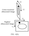
- FIG. 4(a) is a schematic diagram of target position acquisition of a hyperplane ultrasound image follow-up planning embodiment
- FIG. 4(b) is a schematic diagram of a biplanar image coordinate of a hyperplane ultrasound image follow-up planning embodiment.
- the physical positions of the first to fourth index relationships are shown in FIG. 4(a) .
- the ultrasonic probe moves from the coordinates M1 of the physical positions to Mn under the control of the ultrasonic adapter.
- the ultrasonic probe herein may be a convex array probe or linear array probe or biplanar ultrasonic probe.
- the ultrasonic probe is a biplanar ultrasonic probe, and the biplanar ultrasonic probe moves from the coordinates M1 of the physical position to Mn, where M1 is the start physical position of the biplanar ultrasonic probe, and Mn is the end physical position of the biplanar ultrasonic probe.
- the biplanar ultrasonic image is acquired in real time according to a fixed step length, that is, the positions S1 to Sn of the cross-sectional images in the figure represent a position coordinate set of each cross-sectional image, and the positions T1 to Tn of the sagittal images represent a position coordinate set of each sagittal image.
- the biplanar ultrasonic probe may generate a sagittal ultrasonic image shown in FIG. 4(a) at the position Mn.
- the elliptic outline represents an ultrasonic target detection object, and the position of the ultrasonic target detection object is the target position.
- the corresponding cross-sectional ultrasonic image may be generated, such as the positions S1-Sn of the cross-sectional real-time images in the figure.
- the biplanar ultrasonic image is acquired in real time according to the fixed step length, that is, the cross-sectional real-time images S1 to Sn and the sagittal images T1 to Tn in the figure.
- index tables are established: a first index relationship table: ⁇ S1: M1, ..., Sn: Mn ⁇ ], a second index relationship table: [ ⁇ S1: ImgA1, ..., Sn: ImgAn ⁇ ], a third index relationship table: [ ⁇ T1: M1, ..., Tn: Mn ⁇ ], and a fourth index relationship table: [ ⁇ T1: ImgB1, ..., Tn: ImgBn ⁇ ].
- S1 is a start cross section
- Sn is an end cross section
- ImgA1 is a storage position of a start cross-sectional image
- ImgAn is a storage position of an end cross-sectional image.
- T1 is a start sagittal surface
- Tn is an end sagittal surface
- ImgB1 is a storage position of a starting sagittal image
- ImgBn is a storage position of an ending sagittal image.
- FIG. 4(b) shows a relative position relationship between the cross-sectional ultrasonic image and the sagittal ultrasonic image.
- the cross-sectional ultrasonic image and the sagittal ultrasonic image are orthogonal to each other, which can display two sections of a target (black spot in the figure).
- the embodiments of the present application describe that the target position of the target can be displayed in the coordinate system of the cross-sectional image in a follow-up manner after the target position is displayed in the coordinate system of the sagittal image.
- the target position can also be displayed in the coordinate system of the cross-sectional image, and the target position can be displayed in the coordinate system of the sagittal image in a follow-up manner.
- the biplanar ultrasonic probe moves from the coordinates M1 of the physical position to Mn to obtain S1 to Sn of one cross-sectional image and T1 to Tn of one sagittal image.
- the target position is displayed on the cross-sectional image first, and the target position of the target is obtained on the sagittal image in a follow-up manner through the third index relationship table or the fourth index relationship table.
- the ultrasonic probe may be a biplanar ultrasonic probe, or the ultrasonic probe may be a discrete convex array probe and linear array probe.
- the first index relationship table may be expressed as: ⁇ S1: MA1, ..., Sn: MAn ⁇ ], a second index relationship table: [ ⁇ S1: ImgA1, ..., Sn: ImgAn ⁇ ], a third index relationship table: [ ⁇ T1: MB1, ..., Tn: MBn ⁇ ], and a fourth index relationship table: [ ⁇ T1: ImgB1, ..., Tn: ImgBn ⁇ ].
- MA1 is the starting physical position of the convex array probe
- MAn is the ending physical position of the convex array probe
- MB1 is the start physical position of the linear array probe
- MBn is the end physical position of the linear array probe.
- FIG. 5(a) is a method flow of a method embodiment of the present application including an execution flow
- FIG. 5(b) is a schematic diagram of a water jet cutter excision locus of a method embodiment of the present application including an execution flow, which can be applied to the workflow of the water jet cutter.
- a biplanar ultrasonic image planning method specifically includes the following Steps 101-102, 104-106 and 109.
- Step 101 a position relationship between a marker and a cross-sectional image is calibrated to obtain a first conversion matrix, where the first conversion matrix is a matrix converted from a coordinate system of the cross-sectional image to a coordinate system of the marker.
- Step 102 a position relationship between the marker and the sagittal image is calibrated to obtain a second conversion matrix.
- Step 104 a third conversion matrix and or a fourth conversion matrix are/is calculated by a matrix conversion matrix.
- Step 105 a first index relationship table or a second index relationship table is established in the movement process of the ultrasonic probe, where the first index relationship table is an index relationship table of the physical position of the ultrasonic probe and the position of the cross section, and the second index relationship table is an index relationship table of storage position information of the cross-sectional image and the position of the cross section.
- Step 106 the target position displayed in any one of the coordinate system of the cross-sectional image and the coordinate system of the sagittal image is displayed in the other coordinate system in a follow-up manner.
- Step 109 the planned position in the coordinate system of the cross-sectional image or the coordinate system of the sagittal image is converted into a motion and or energy execution parameter.
- the motion execution parameter is a parameter for controlling an execution mechanism to move
- the energy execution parameter is a parameter for controlling the execution mechanism to release energy
- water jet cutting is a process of releasing energy
- water jet is a process of releasing energy
- the execution mechanism may be manually controlled to move according to the planned position and execute according to the planned energy, or may be automatically controlled to move according to the planned position and execute according to the planned energy.
- planned energy refers to planned energy for the execution mechanism to generate and release.
- An execution module may be a water jet cutter, an electrotome, a laser knife, an ultrasound knife or other execution mechanisms, which is not particularly limited here.
- the water jet cutter or other execution mechanisms are manually controlled to perform movement and resection along the planned position.
- the water jet cutter or other execution mechanisms are automatically controlled to perform movement and resection along the planned position through a motor and an energy generation apparatus of the execution mechanism.
- Step 109 the water jet cutting trajectory on the generated biplanar ultrasonic image is shown in FIG. 5(b) , where the shaded part is the water jet cutting trajectory on the sagittal image, ⁇ 1 to ⁇ 4 are cross-sectional ultrasonic fan-shaped trajectories at the corresponding positions on the sagittal plane, and the fan-shaped position can be linked and planned at any position on the sagittal plane.
- S_img [([y0_start, z0_start], [y0_end, z0_end], ⁇ 0_start, ⁇ 0_end), ([y1_start, z1_start], [y1_end, z1_end], ⁇ 1_start, ⁇ 1_end), (13), ..., and ([yn_start, zn_start], [yn_end,zn_end], ⁇ n_start, ⁇ n_end)]
- z0_start and z0_end respectively represent a start value and an end value of the z-axis coordinates of the sagittal plane of water jet cutting in the 0 th movement voxel.
- ⁇ 0_start and ⁇ 0_end respectively represent a start value and an end value of a cross-sectional included angle of water jet cutting in the 0 th movement voxel.
- xy plane represents the cross section
- yz plane represents the sagittal plane
- S_motor represents the motion execution parameter, and the resection action can be completed by controlling the water jet cutter or other execution mechanisms to move according to the parameter trajectory S_motor.
- the energy of the water jet cutter can be controlled through the movement of the water jet cutter energy generation apparatus, and the conversion relationship has been included in Ts.
- FIG. 6 is a method flowchart of a method embodiment of the present application including a water jet cutter.
- the marker is a convex array probe, and the coordinate system of the marker is the coordinate system of the convex array probe; and the second ultrasonic probe is a linear array probe, and the coordinate system of the second ultrasonic probe is the coordinate system of the linear array probe.
- the convex array probe and the linear array probe are two independent probes, which can perform coordinate system calibration during use.
- a biplanar ultrasonic image planning method specifically includes the following Steps 201-204.
- Step 201 a position relationship between the marker and the cross-sectional image is calibrated to obtain a first conversion matrix.
- the first conversion matrix is a matrix converted from the coordinate system of the cross-sectional image to the coordinate system of the convex array probe.
- the method for calculating the first conversion matrix in the Step 201 is the same as that in the Step 101, which is not elaborated herein.
- Step 202 the position relationship between the second ultrasonic probe and the sagittal image is calibrated, the position relationship between the second ultrasonic probe and the marker is calibrated, and the second conversion matrix is obtained by the matrix conversion relationship.
- the position relationship between the linear array probe and the sagittal image is calibrated
- the position relationship between the linear array probe and the convex array probe is calibrated
- the second conversion matrix can be obtained.
- the second conversion matrix is a matrix converted from the coordinate system of the sagittal image to the coordinate system of the convex array probe.
- the method for calibrating the position relationship between the linear array probe and the sagittal image in the Step 202 is the same as that in the Step 102, which is not elaborated herein.
- the method for calibrating the position relationship between the linear array probe and the convex array probe may be: performing calibration by converting the coordinate system of the linear array probe and the convex array probe into the same fixed coordinate system, or may be: directly converting the coordinate system of the linear probe into the coordinate system of the convex array probe or converting the coordinate system of the convex array probe into the coordinate system of the linear array probe.
- the coordinate system of the convex array probe refers to a coordinate system established by taking the centroid of a positioning and tracking sensor in the convex array probe as the origin
- the coordinate system of the linear array probe refers to a coordinate system established by taking the centroid of a positioning and tracking sensor in the linear array probe as the origin.
- Step 203 a third conversion matrix and or a fourth conversion matrix are/is calculated by a matrix conversion relationship, and a target position and a planned position displayed in any one of the coordinate system of the cross-sectional image and the coordinate system of the sagittal image are displayed in the other coordinate system in a follow-up manner.
- the target position and the planned position can be displayed in the coordinate system of the cross-sectional image, and the target position and the planned position can be displayed in the coordinate system of the sagittal image in a follow-up manner.
- the target position and the planned position can be displayed in the coordinate system of the sagittal image, and the corresponding target position and planned position can be displayed in the coordinate system of the cross-sectional image in a follow-up manner.
- Step 204 a planned position in the coordinate system of the cross-sectional image or the coordinate system of the sagittal image is converted into a motion or energy execution parameter, where the motion or energy execution parameter is a parameter for controlling the motion and energy of an execution mechanism.
- the method for obtaining the motion or energy execution parameter in the Step 204 is the same as that in the Step 109, which is not elaborated herein.
- Step 204 surgical planning is performed on the sagittal image based on the zero point position probe, any point on the sagittal image is selected, and the cross-sectional image corresponding to the Z-direction coordinate position can be calculated by the Steps 201-203.
- the ultrasonic adapter can be controlled according to the Step 106 in the method 1 to move the ultrasonic probe to the target position to acquire and display a real-time ultrasonic cross-sectional image in a follow-up manner, or the acquired cross-sectional image can be displayed in a follow-up manner directly according to the position and according to the Step 106 in the method 2.
- the error between the Z-coordinate position of the cross-sectional image and the Z-coordinate position selected by planning is determined by an image sampling rate in the motion and acquisition position of the cross-sectional image.
- the relative position of the rectal ultrasound biplane is accurately calibrated, a relative position relationship of images (cross section and sagittal plane) respectively generated by two probe arrays at the same motion position can be obtained through calculation, and a position conversion matrix can be generated.
- the embodiments of the present application provide a water jet cutting process.
- the automatic water jet cutting process can be implemented according to the trajectory positions in the linear array probe and the convex array probe, so that the water jet cutting process is more accurate. It should be noted that the water jet cutting process of the present application can further be implemented through a biplanar ultrasonic probe or a three-dimensional probe.
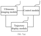
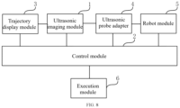
- FIG. 7(a) is a schematic structural diagram of an apparatus embodiment of the present application
- FIG. 7(b) is another schematic structural diagram of an apparatus embodiment of the present application, which can be used to implement the method according to any embodiment of the present application.
- a biplanar ultrasound image planning apparatus includes an ultrasonic imaging module 1, a control module 2 and a display module 3.
- the ultrasonic imaging module is configured to acquire a position of a marker and generate a cross-sectional image and a sagittal image.
- the control module is configured to: establish a coordinate system of the marker according to the position of the marker, and respectively and correspondingly establish a coordinate system of the cross-sectional image and a coordinate system of the sagittal image according to the positions of the cross-sectional image and the sagittal image; calculate a first conversion matrix converted from the coordinate system of the cross-sectional image to the coordinate system of the marker, and a second conversion matrix converted from the coordinate system of the sagittal image to the coordinate system of the marker; and calculate a third conversion matrix and or a fourth conversion matrix by a matrix conversion matrix.
- the display module is configured to: according to a target position in any one of the coordinate system of the cross-sectional image and the coordinate system of the sagittal image, display a target position in the other coordinate system in a follow-up manner.
- the ultrasonic imaging module is an intracavity biplanar ultrasonic probe system
- the control system controls the action of each module to calculate, generate and store each conversion matrix and each index relationship table.
- the ultrasonic imaging module includes: a biplanar ultrasonic probe and a positioning needle, where the marker is the biplanar ultrasonic probe.
- a positioning and tracking sensor is arranged in the biplanar ultrasonic probe and configured to acquire the position of the biplanar ultrasonic probe.
- a positioning and tracking sensor is arranged in a needle body of the positioning needle and configured to acquire the position of the positioning needle and the position of a positioning needle point.
- the control module is further configured to: establish a coordinate system of the positioning needle to a coordinate system of the positioning needle point according to the positions of the positioning needle and the positioning needle point; and calculate a fifth conversion matrix by a positioning needle correction method and calculate a sixth to eighth conversion matrices so as to obtain the first conversion matrix.
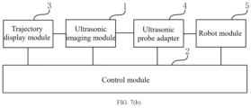
- a biplanar ultrasonic image planning apparatus includes: an ultrasonic imaging module 1, a control module 2, a display module 3, an ultrasonic adapter probe 4 and a robot module 5.
- the biplanar ultrasonic probe in the ultrasonic imaging module can be fixed through the ultrasonic probe adapter, and the degrees of freedom in at least two directions of straight line and rotation are provided for the biplanar ultrasonic probe.
- the biplanar ultrasonic probe and the ultrasonic probe adapter can be fixed through the robot module.
- control module is further configured to: establish a first index relationship table or a second index relationship table in the movement process of the biplanar ultrasonic probe; and display the target position and planned position in the cross-sectional image in a follow-up manner according to the target position and planned position in the sagittal image and by using the first index relationship table or the second index relationship table in the real-time surgical planning.
- control module is further configured to: establish a third index relationship table or a fourth index relationship table in the movement process of the ultrasonic probe; and display the target position and planned position in the sagittal image in a follow-up manner according to the target position and planned position in the cross-sectional image and by using the third index relationship table or the fourth index relationship table in the real-time surgical planning.
- FIG. 8 is another embodiment of an apparatus of the present application, which can use the method according to any embodiment of the present application.
- a biplanar ultrasound image planning apparatus includes: an ultrasonic imaging module 1, a control module 2, a trajectory display module 3, an ultrasonic adapter probe 4, a robot module 5 and an execution module 6.
- the ultrasonic imaging module is configured to acquire positions of a convex array probe and a linear array probe and generate a cross-sectional image and a sagittal image.
- the control module is configured to: respectively establish a coordinate system of the convex array probe and a coordinate system of the linear array probe according to the positions of the convex array probe and the linear array probe, and respectively establish a coordinate system of the cross-sectional image and a coordinate system of the sagittal image according to the positions of the cross-sectional image and the sagittal image.
- the control module is further configured to calculate a first conversion matrix converted from the coordinate system of the cross-sectional image to the coordinate system of the convex array probe, and a second conversion matrix converted from the coordinate system of the sagittal image to the coordinate system of the linear array probe; and calculate a third conversion matrix and or a fourth conversion matrix by a matrix conversion matrix.
- the ultrasonic probe adapter is configured to fix the convex array probe or the linear array probe in the ultrasonic imaging module, and provide the degrees of freedom in at least two directions of straight line and rotation for the convex array probe and the linear array probe.
- the robot module is configured to fix the convex array probe, the linear array probe and the ultrasonic probe adapter.
- the execution module is configured to convert the planned position in the coordinate system of the cross-sectional image or the coordinate system of the sagittal image into motion and energy execution parameters, and control an execution mechanism to move and generate energy.
- the execution module may be a water jet cutter, an electrotome, a laser knife, an ultrasound knife or other execution mechanisms.
- the execution module may be controlled manually or automatically to move and perform resection. If the execution module is controlled automatically to move and perform resection, a motor of the execution module is driven to automatically control the execution module to move and automatically control the energy of an energy generation apparatus.
- the ultrasonic imaging module includes: a convex array probe and a linear array probe.
- the convex array probe is configured to acquire the position of the marker and the position of the cross-sectional image.
- the linear array probe is configured to acquire the position of the second ultrasonic probe and the position of the cross-sectional image.
- the control module is further configured to establish a coordinate system of the second ultrasonic probe, calibrate the position relationship between the second ultrasonic probe and the sagittal image, calibrate the position relationship between the second ultrasonic probe and the marker, and perform calculation by the matrix conversion relationship to obtain the second conversion matrix.
- the biplanar ultrasonic probe is fixed and controlled by the ultrasonic probe adapter with high-precision position feedback, so that accurate surgical planning can be achieved.
- the ultrasonic probe adapter drives a dual-array ultrasonic probe to move automatically, scans the whole organ and acquires continuous images of each cross section of the organ to accurately correspond to each position of the sagittal plane to achieve fine surgical planning, thereby implementing high-precision tissue ablation, performing fine tissue ablation along the actual boundary of the organ, achieving an ideal surgical effect, and avoiding the surgical planning error of the organ model caused by manual acquisition of a limited ultrasonic image.
- a device of the present application includes one or more processors (one of CPU, FGAP and MUC), input/output user interfaces, network interfaces and memories.
- the present application may use a form of a computer program product that is implemented on one or more computer-usable storage media (including but not limited to a disk memory, a CD-ROM, an optical memory and the like) that include computer-usable program code.
- a computer-usable storage media including but not limited to a disk memory, a CD-ROM, an optical memory and the like.
- the present application further provides a computer-readable medium, where the computer-readable medium stores a computer program; and when the computer program is executed by a processor, the steps of the method according to any embodiment of the present application are implemented.
- the memory of the present application may include a non-permanent memory, a random access memory (RAM), a non-volatile memory and or the like in the computer-readable medium, such as a read-only memory (ROM) or a flash RAM.
- the computer-readable medium includes permanent and non-permanent, removable and non-removable media, and may store information by using any method or technology.
- the information may be computer-readable instructions, data structures, modules of programs or other data.
- Examples of the computer storage medium include but not limited to: a phase-change memory (PRAM), a static random access memory (SRAM), a dynamic random access memory (DRAM), another type of random access memory (RAM), a read-only memory (ROM), an electrically erasable programmable read-only memory (EEPROM), a flash memory or another memory technology, a compact disc read-only memory (CD-ROM), a digital video disc (DVD) or another optical memory, a magnetic cassette, a magnetic disk storage, another magnetic storage device, and any other non-transmission media that may be configured to store information that can be accessed by a computing device.
- the computer-readable medium does not include computer-readable transitory media, such as modulated data signals and carriers.
Landscapes
- Health & Medical Sciences (AREA)
- Life Sciences & Earth Sciences (AREA)
- Engineering & Computer Science (AREA)
- Surgery (AREA)
- Heart & Thoracic Surgery (AREA)
- Veterinary Medicine (AREA)
- Nuclear Medicine, Radiotherapy & Molecular Imaging (AREA)
- Public Health (AREA)
- General Health & Medical Sciences (AREA)
- Biomedical Technology (AREA)
- Animal Behavior & Ethology (AREA)
- Medical Informatics (AREA)
- Molecular Biology (AREA)
- Physics & Mathematics (AREA)
- Biophysics (AREA)
- Radiology & Medical Imaging (AREA)
- Pathology (AREA)
- Robotics (AREA)
- Gynecology & Obstetrics (AREA)
- Vascular Medicine (AREA)
- Computer Vision & Pattern Recognition (AREA)
- Ultra Sonic Daignosis Equipment (AREA)
Applications Claiming Priority (2)
| Application Number | Priority Date | Filing Date | Title |
|---|---|---|---|
| CN202210291564.XA CN114376610B (zh) | 2022-03-24 | 2022-03-24 | 一种双平面超声图像规划方法和装置 |
| PCT/CN2023/083618 WO2023179756A1 (zh) | 2022-03-24 | 2023-03-24 | 一种双平面超声图像规划方法和装置 |
Publications (2)
| Publication Number | Publication Date |
|---|---|
| EP4501243A1 true EP4501243A1 (de) | 2025-02-05 |
| EP4501243A4 EP4501243A4 (de) | 2025-07-09 |
Family
ID=81205163
Family Applications (1)
| Application Number | Title | Priority Date | Filing Date |
|---|---|---|---|
| EP23774001.4A Pending EP4501243A4 (de) | 2022-03-24 | 2023-03-24 | Zweiebenen-ultraschallbildplanungsverfahren und -vorrichtung |
Country Status (4)
| Country | Link |
|---|---|
| US (1) | US20250017662A1 (de) |
| EP (1) | EP4501243A4 (de) |
| CN (1) | CN114376610B (de) |
| WO (1) | WO2023179756A1 (de) |
Families Citing this family (8)
| Publication number | Priority date | Publication date | Assignee | Title |
|---|---|---|---|---|
| CN114376610B (zh) * | 2022-03-24 | 2022-06-10 | 北京智愈医疗科技有限公司 | 一种双平面超声图像规划方法和装置 |
| CN115444513B (zh) * | 2022-04-24 | 2024-06-25 | 北京智愈医疗科技有限公司 | 一种自动水刀实现方法和设备 |
| US12380563B2 (en) * | 2022-05-30 | 2025-08-05 | Shantou Institute Of Ultrasonic Instruments Co., Ltd. | Convex-linear bi-plane probe and its application method in prostate volume calculation |
| US12329574B2 (en) | 2022-10-31 | 2025-06-17 | Procept Biorobotics Corporation | Fiducial systems for probe tracking and identification |
| CN115607282B (zh) * | 2022-12-02 | 2023-04-07 | 北京智愈医疗科技有限公司 | 一种水刀轨迹预设方法和装置 |
| CN117281551A (zh) * | 2023-10-19 | 2023-12-26 | 苏州大学附属第二医院 | 一种改进型生殖超声检测系统及方法 |
| CN119229150B (zh) * | 2024-12-02 | 2025-03-04 | 北京智愈医疗科技有限公司 | 一种水刀的偏转程度识别方法及系统 |
| CN120616760A (zh) * | 2025-04-27 | 2025-09-12 | 北京智愈医疗科技有限公司 | 一种增强现实影像导航方法和装置 |
Family Cites Families (11)
| Publication number | Priority date | Publication date | Assignee | Title |
|---|---|---|---|---|
| US5396890A (en) * | 1993-09-30 | 1995-03-14 | Siemens Medical Systems, Inc. | Three-dimensional scan converter for ultrasound imaging |
| JP3691895B2 (ja) * | 1996-01-19 | 2005-09-07 | 株式会社日立メディコ | 超音波診断装置 |
| US9271678B2 (en) * | 2011-04-08 | 2016-03-01 | Siemens Aktiengesellschaft | Constrained registration for motion compensation in atrial fibrillation ablation procedures |
| US20120289836A1 (en) * | 2011-05-12 | 2012-11-15 | Osamu Ukimura | Automatic real-time display system for the orientation and location of an ultrasound tomogram in a three-dimensional organ model |
| CN106510760B (zh) * | 2016-11-29 | 2023-03-14 | 苏州国科康成医疗科技有限公司 | 基于双截面超声探头的标定系统及标定方法 |
| US11364012B2 (en) * | 2017-05-31 | 2022-06-21 | Bk Medical Aps | 3-D imaging via free-hand scanning with a multiplane US transducer |
| EP3613352A1 (de) * | 2018-08-21 | 2020-02-26 | Koninklijke Philips N.V. | Systeme und verfahren zur ausführung von bildgebung auf zwei ebenen |
| CN110169823A (zh) * | 2019-04-24 | 2019-08-27 | 艾瑞迈迪科技石家庄有限公司 | 超声探头标定方法、装置、终端及存储介质 |
| CN115426954A (zh) * | 2020-04-16 | 2022-12-02 | 皇家飞利浦有限公司 | 用于生成路线图图像的双平面和三维超声图像采集以及相关联的系统和设备 |
| CN113133832B (zh) * | 2021-03-26 | 2022-09-20 | 中国科学院深圳先进技术研究院 | 一种双臂机器人穿刺系统标定方法及系统 |
| CN114376610B (zh) * | 2022-03-24 | 2022-06-10 | 北京智愈医疗科技有限公司 | 一种双平面超声图像规划方法和装置 |
-
2022
- 2022-03-24 CN CN202210291564.XA patent/CN114376610B/zh active Active
-
2023
- 2023-03-24 EP EP23774001.4A patent/EP4501243A4/de active Pending
- 2023-03-24 WO PCT/CN2023/083618 patent/WO2023179756A1/zh not_active Ceased
-
2024
- 2024-09-24 US US18/895,339 patent/US20250017662A1/en active Pending
Also Published As
| Publication number | Publication date |
|---|---|
| US20250017662A1 (en) | 2025-01-16 |
| CN114376610B (zh) | 2022-06-10 |
| EP4501243A4 (de) | 2025-07-09 |
| CN114376610A (zh) | 2022-04-22 |
| WO2023179756A1 (zh) | 2023-09-28 |
Similar Documents
| Publication | Publication Date | Title |
|---|---|---|
| EP4501243A1 (de) | Zweiebenen-ultraschallbildplanungsverfahren und -vorrichtung | |
| US11911214B2 (en) | System and methods for at home ultrasound imaging | |
| US5810008A (en) | Apparatus and method for visualizing ultrasonic images | |
| US7085400B1 (en) | System and method for image based sensor calibration | |
| US7677078B2 (en) | Line-based calibration of ultrasound transducer integrated with a pose sensor | |
| Megali et al. | A computer-assisted robotic ultrasound-guided biopsy system for video-assisted surgery | |
| CN113940755A (zh) | 一种术像一体的外科手术规划与导航方法 | |
| CN112754616B (zh) | 超声定位穿刺系统和存储介质 | |
| WO2022141153A1 (zh) | 超声定位穿刺系统和存储介质 | |
| Krupa et al. | Full motion tracking in ultrasound using image speckle information and visual servoing | |
| Cai et al. | A low-cost camera-based ultrasound probe tracking system: Design and prototype | |
| US5660179A (en) | Ultrasonic diagnostic apparatus | |
| US20260007474A1 (en) | Minimally invasive puncture system based on navigation system | |
| EP3142560B1 (de) | Medizinisches bildverarbeitungssystem und verfahren dafür | |
| CN120514474A (zh) | 一种面向软组织介入穿刺手术机器人的空间配准及图像引导方法 | |
| Cai et al. | Spatial calibration for 3d freehand ultrasound via independent general motions | |
| CN111821026A (zh) | 单点定位手术器械、标定工具及标定方法 | |
| CN116919592A (zh) | 一种基于c臂机影像的导航方法及系统 | |
| Cai et al. | Development of robot-assisted ultrasound system for fetoscopic tracking in twin to twin transfusion syndrome surgery | |
| CN117765035A (zh) | 超声图像和ct图像配准方法、装置、计算机设备及介质 | |
| JP7027029B2 (ja) | 超音波診断装置および医用画像処理装置 | |
| Sun et al. | A primary study: Automatic ultrasound acquisition system based on visual servo | |
| CN117643478A (zh) | 一种图像叠加系统、方法及设备 | |
| Hashemi | 3D Shape Estimation Of Tendon-Driven Catheters Using Ultrasound Imaging | |
| CN120267369A (zh) | 基于穿刺针自旋的针尖位置校准方法、装置、系统、设备及穿刺针系统 |
Legal Events
| Date | Code | Title | Description |
|---|---|---|---|
| STAA | Information on the status of an ep patent application or granted ep patent |
Free format text: STATUS: THE INTERNATIONAL PUBLICATION HAS BEEN MADE |
|
| PUAI | Public reference made under article 153(3) epc to a published international application that has entered the european phase |
Free format text: ORIGINAL CODE: 0009012 |
|
| STAA | Information on the status of an ep patent application or granted ep patent |
Free format text: STATUS: REQUEST FOR EXAMINATION WAS MADE |
|
| 17P | Request for examination filed |
Effective date: 20240924 |
|
| AK | Designated contracting states |
Kind code of ref document: A1 Designated state(s): AL AT BE BG CH CY CZ DE DK EE ES FI FR GB GR HR HU IE IS IT LI LT LU LV MC ME MK MT NL NO PL PT RO RS SE SI SK SM TR |
|
| DAV | Request for validation of the european patent (deleted) | ||
| DAX | Request for extension of the european patent (deleted) | ||
| A4 | Supplementary search report drawn up and despatched |
Effective date: 20250606 |
|
| RIC1 | Information provided on ipc code assigned before grant |
Ipc: A61B 8/08 20060101ALI20250602BHEP Ipc: A61B 8/12 20060101ALI20250602BHEP Ipc: A61B 34/20 20160101ALI20250602BHEP Ipc: A61B 8/02 20060101ALI20250602BHEP Ipc: A61B 34/10 20160101ALI20250602BHEP Ipc: A61B 8/00 20060101AFI20250602BHEP |