EP4498741A1 - Signalmessverfahren und -vorrichtung sowie vorrichtung, medium und programmprodukt - Google Patents
Signalmessverfahren und -vorrichtung sowie vorrichtung, medium und programmprodukt Download PDFInfo
- Publication number
- EP4498741A1 EP4498741A1 EP22925506.2A EP22925506A EP4498741A1 EP 4498741 A1 EP4498741 A1 EP 4498741A1 EP 22925506 A EP22925506 A EP 22925506A EP 4498741 A1 EP4498741 A1 EP 4498741A1
- Authority
- EP
- European Patent Office
- Prior art keywords
- time domain
- domain position
- symbols
- criterion
- bandwidth part
- Prior art date
- Legal status (The legal status is an assumption and is not a legal conclusion. Google has not performed a legal analysis and makes no representation as to the accuracy of the status listed.)
- Pending
Links
Images

Classifications
-
- H—ELECTRICITY
- H04—ELECTRIC COMMUNICATION TECHNIQUE
- H04L—TRANSMISSION OF DIGITAL INFORMATION, e.g. TELEGRAPHIC COMMUNICATION
- H04L5/00—Arrangements affording multiple use of the transmission path
- H04L5/003—Arrangements for allocating sub-channels of the transmission path
- H04L5/0048—Allocation of pilot signals, i.e. of signals known to the receiver
-
- H—ELECTRICITY
- H04—ELECTRIC COMMUNICATION TECHNIQUE
- H04W—WIRELESS COMMUNICATION NETWORKS
- H04W64/00—Locating users or terminals or network equipment for network management purposes, e.g. mobility management
-
- G—PHYSICS
- G01—MEASURING; TESTING
- G01S—RADIO DIRECTION-FINDING; RADIO NAVIGATION; DETERMINING DISTANCE OR VELOCITY BY USE OF RADIO WAVES; LOCATING OR PRESENCE-DETECTING BY USE OF THE REFLECTION OR RERADIATION OF RADIO WAVES; ANALOGOUS ARRANGEMENTS USING OTHER WAVES
- G01S5/00—Position-fixing by co-ordinating two or more direction or position line determinations; Position-fixing by co-ordinating two or more distance determinations
- G01S5/02—Position-fixing by co-ordinating two or more direction or position line determinations; Position-fixing by co-ordinating two or more distance determinations using radio waves
- G01S5/0205—Details
-
- H—ELECTRICITY
- H04—ELECTRIC COMMUNICATION TECHNIQUE
- H04W—WIRELESS COMMUNICATION NETWORKS
- H04W72/00—Local resource management
- H04W72/04—Wireless resource allocation
- H04W72/044—Wireless resource allocation based on the type of the allocated resource
- H04W72/0446—Resources in time domain, e.g. slots or frames
-
- H—ELECTRICITY
- H04—ELECTRIC COMMUNICATION TECHNIQUE
- H04W—WIRELESS COMMUNICATION NETWORKS
- H04W72/00—Local resource management
- H04W72/20—Control channels or signalling for resource management
- H04W72/23—Control channels or signalling for resource management in the downlink direction of a wireless link, i.e. towards a terminal
-
- H—ELECTRICITY
- H04—ELECTRIC COMMUNICATION TECHNIQUE
- H04W—WIRELESS COMMUNICATION NETWORKS
- H04W24/00—Supervisory, monitoring or testing arrangements
- H04W24/10—Scheduling measurement reports ; Arrangements for measurement reports
-
- H—ELECTRICITY
- H04—ELECTRIC COMMUNICATION TECHNIQUE
- H04W—WIRELESS COMMUNICATION NETWORKS
- H04W76/00—Connection management
- H04W76/20—Manipulation of established connections
- H04W76/27—Transitions between radio resource control [RRC] states
-
- H—ELECTRICITY
- H04—ELECTRIC COMMUNICATION TECHNIQUE
- H04W—WIRELESS COMMUNICATION NETWORKS
- H04W88/00—Devices specially adapted for wireless communication networks, e.g. terminals, base stations or access point devices
- H04W88/18—Service support devices; Network management devices
Definitions
- the present invention relates to the communication field, and in particular to a signal measurement method and apparatus, a device, a medium and a program product.
- a method for positioning a terminal also called User Equipment, UE
- RRC Inactive radio resource control inactive
- Embodiments of the present invention provide a signal measurement method and apparatus, a device, a medium, and a program product. Described technical solutions will be described as follows.
- a signal measurement method includes: determining whether to measure a positioning reference signal according to a first time domain position of downlink information and a second time domain position of the positioning reference signal.
- a signal measurement method includes: receiving a criterion reported by a terminal, in which the criterion is used for determining whether to measure a positioning reference signal according to a first time domain position of downlink information and a second time domain position of the positioning reference signal.
- a signal measurement apparatus includes: a processing module, configured to determine whether to measure a positioning reference signal according to a first time domain position of downlink information and a second time domain position of the positioning reference signal.
- a signal measurement apparatus includes: a receiving module, configured to receive a criterion reported by a terminal, in which the criterion is used for determining whether to measure a positioning reference signal according to a first time domain position of downlink information and a second time domain position of the positioning reference signal.
- a terminal includes:
- the processor is configured to load and execute executable instructions to implement steps at the terminal side in the signal measurement method described in the above various aspects.
- an access network device and/or a location server includes:
- the processor is configured to load and execute executable instructions to implement steps at the access network device and/or location server side in the signal measurement method described in the above various aspects.
- a computer-readable storage medium has at least one instruction, at least one program, a code set or an instruction set stored therein.
- the at least one instruction, the at least one program, the code set or the instruction set is loaded and executed by a processor to implement the signal measurement method described in the above various aspects.
- the terminal may determine whether there is the reception conflict between downlink information and a positioning reference signal based on a first time domain position of the downlink information and a second time domain position of the positioning reference signal.
- a criterion for selecting to measure or not to measure the positioning reference signal i.e., whether to measure the positioning reference signal is provided.
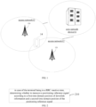
- FIG 1 is a schematic diagram illustrating a communication system according to an embodiment of the invention.
- the communication system may include: an access network 12, a user terminal 14 and a core network device 16.
- the access network 12 includes multiple access network devices 120.
- the access network device 120 may be a base station.
- the base station is an apparatus deployed in the access network and configured to provide a wireless communication function for the user terminal (terminal for short) 14.
- the base station may include various forms of macro stations, micro base stations, relay stations, access points and the like. Names of a device with a base station function may be different in systems with different wireless access technologies. For example, the device is called eNodeB or eNB in a long-term evolution (LTE) system, and the device is called gNB or gNodeB in a 5G new radio (NR) system. With the development of communication technologies, the name "base station" may be described and changed.
- a transmission reception point (TRP) is further introduced.
- Each access network device can contain at least one TRP. Multiple TRPs send positioning reference signals.
- the terminal measures the positioning reference signals sent by the multiple TRPs and reports measurement results. For some of these TRPs, transmission is performed by the access network devices belonging to a serving cell of the terminal. For some of these TRPs, transmission is performed by the access network devices belonging to an adjacent cell (that is, a non-serving cell) of the terminal.
- the above apparatuses for providing the wireless communication function for the terminal are collectively referred to as the network device.
- the terminal 14 may include various handheld devices, vehicle-mounted devices, wearable devices, and computing devices having the wireless communication function, or other processing devices connected to a wireless modem, various forms of terminals (UEs), mobile stations (MSs), terminal devices, and the like. For the convenience of description, the above devices are collectively referred to as the user terminal.
- the access network device 120 communicates with the user terminal 14 through some air interface technologies, such as a Uu interface.
- the core network device 16 includes a location management function network element.
- the location management function network element includes a location server, and the location server can be implemented as any of the following: location management function (LMF), enhanced serving mobile location centre (E-SMLC), secure user plane location (SUPL), SUPL location platform (SUPL SLP).
- LMF location management function
- E-SMLC enhanced serving mobile location centre
- SUPL secure user plane location
- SUPL SLP SUPL location platform
- LPF LTE positioning protocol
- GSM Global System of Mobile Communication
- CDMA Code Division Multiple Access
- WCDMA Wideband Code Division Multiple Access
- GPRS General Packet Radio Service
- LTE Long Term Evolution
- FDD Frequency Division Duplex
- TDD Time Division Duplex
- LTE-A Advanced long Term Evolution
- NR New Radio
- UMTS Universal Mobile Telecommunication System
- WiMAX Worldwide Interoperability for Microwave Access
- WLAN Wireless Local Area Networks
- WiFi Wireless Fidelity
- D2D Device to Device
- M2M Machine to Machine
- MTC Machine Type Communication
- V2V Vehicle to Vehicle
- V2X Vehicle to Everything
- the downlink information refers to information sent by an access network device, and the downlink information includes a downlink channel and/or signal.
- the downlink channel and/or signal includes at least one of the following:
- the downlink information is sent by the access network device on an initial downlink bandwidth part (initial DL BWP) of the terminal.
- initial DL BWP initial downlink bandwidth part
- the first time domain position of the downlink information and the second time domain position of the positioning reference signal are obtained.
- the above first time domain position refers to a time domain resource occupied by the network device for sending the downlink information to the terminal in a downlink scenario.
- the above second time domain position refers to a time domain resource occupied by the access network device for sending the PRS to the terminal in the downlink scenario.
- the terminal determines, according to the first time domain position and the second time domain position, whether the time domain resources occupied by the downlink information and the positioning reference signal overlap partially or entirely (that is, determining whether there is a reception conflict between the downlink information and the positioning reference signal), and then determines whether to measure the positioning reference signal based on whether there is the reception conflict between the downlink information and the positioning reference signal.
- the above reception conflict means that the time domain resource required for receiving the downlink information and the time domain resource required for receiving the PRS partially or entirely overlap, or a time interval between the time domain resources is smaller than a time interval threshold (that is, the time interval is small).
- the first time domain position and/or the second time domain position is configured for the terminal by the access network device; or configured for the terminal by the location server.
- the above first time domain position and the above second time domain position may be time domain positions on a same frequency domain, or time domain positions on different frequency domains, such as time domain positions on different bandwidth parts (BWPs).
- BWPs bandwidth parts
- the positioning reference signal is not measured. If the terminal determines, based on the first time domain position and the second time domain position, that the time domain resources occupied by the downlink information and the positioning reference signal partially or entirely overlap, or the time interval between the time domain resources is less than the time interval threshold, that is, determining that there is the reception conflict between the downlink information and the positioning reference signal, then the positioning reference signal is not measured. If the terminal determines, based on the first time domain position and the second time domain position, that the time domain resources occupied by the downlink information and the positioning reference signal do not overlap, or the time interval is greater than or equal to the time interval threshold, that is, determining that there is no reception conflict between the downlink information and the positioning reference signal, then the positioning reference signal is measured.
- the terminal when the terminal is in the RRC inactive state, the terminal may determine, based on the first time domain position of the downlink information and the second time domain position of the positioning reference signal, whether there is a reception conflict between the downlink information and the positioning reference signal, so that a criterion for selecting to measure or not to measure the positioning reference signal (i.e., whether to measure the positioning reference signal) is provided.
- the above positioning reference signal can be located on the initial downlink bandwidth part, that is, on the same DLBWP as the downlink information.
- the positioning reference signal can also be located on a downlink bandwidth part other than the initial downlink bandwidth part. For the above two different scenarios, the manners of the terminal determining whether to measure the positioning reference signal are different.
- the terminal uses a first criterion to determine whether to measure the positioning reference signal, as shown in FIG 3 , the step 210 may include a step 310 as shown below.
- step S310 in case of the terminal being in the RRC inactive state, whether to measure the positioning reference signal is determined based on whether the first time domain position and the second time domain position conform to the first criterion.
- the first criterion includes at least one of a criterion type 1 or a criterion type 2.
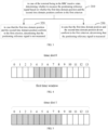
- the criterion type 1 includes a criterion that there is an overlap between a first symbol in the first time domain position and a second symbol in the second time domain position.
- the criterion type 2 includes a criterion that the second symbol in the second time domain position is within a first time window, in which the first time window refers to a time window corresponding to the first time domain position.
- the above first time window is a time window corresponding to the first time domain position in case that the positioning reference signal is located on the initial downlink bandwidth part.
- the first time window includes symbols at the first time domain position, X1 symbols before the first time domain position, and Y1 symbols after the first time domain position, where X1 and Y1 are non-negative integers.
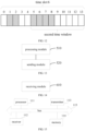
- a time slot 0 includes 14 symbols 0-13. Assuming that the first time domain position of the downlink information includes symbols 4-8 on the time slot 0, X1 takes a value of 2, and Y1 takes a value of 1, the terminal determines that the first time window includes symbols 2-9 on the time slot 0.
- the X1 symbols and the Y1 symbols are determined based on a subcarrier spacing of the initial downlink bandwidth part.
- the terminal obtains the subcarrier spacing of the initial downlink bandwidth part after determining to adopt the criterion type 2, or after starting a positioning function, or after starting the device itself, and determines, based on the subcarrier spacing of the initial downlink bandwidth part, the X1 symbols and the Y1 symbols and/or a symbol length of each of the X1 symbols and the Y1 symbols.
- the terminal After determining the values of X1 and Y1, the terminal reports its capability to the access network device and/or the location server. For example, the terminal can report X1 and Y1 to the access network device and/or the location server. For another example, the terminal can also report, to the access network device and/or the location server, that at least one of the criterion type 1 or the decision criterion type 2 is supported. In this way, the access network device and/or the location server can clearly know the PRS received by the terminal.
- the terminal performs steps 320 to 330 according to a determination result as follows.
- the terminal determines not to measure the positioning reference signal.
- the first time domain position includes symbols 0-6 on a time slot 1
- the second time domain position includes symbols 4-8 on the time slot 1
- the symbols 4-6 in the first time domain position and the symbols 4-6 in the second time domain position overlap, it is determined that the first time domain position and the second time domain position conform to the criterion type 1, and the terminal does not measure the positioning reference signal.
- the terminal determines not to measure the positioning reference signal. That is, if some or all symbols in the second time domain position are within the first time window, the terminal determines not to measure the positioning reference signal.
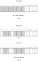
- the first time domain position includes symbols 4-8 on a time slot 2
- the second time domain position includes symbols 0-3 on the time slot 2.
- the first time window includes symbols 3 to 9, therefore, symbol 3 in the second time domain position is within the first time window, the terminal determines that the first time domain position and the second time domain position conform to the criterion type 2, and the terminal does not measure the positioning reference signal.
- the terminal determines not to measure the positioning reference signal when the first time domain position and the second time domain position conform to the criterion type 1 and the criterion type 2.
- the terminal determines not to measure the positioning reference signal when the first time domain position and the second time domain position conform to the criterion type 1 or the criterion type 2.
- step 330 in case that the first time domain position and the second time domain position do not conform to the first criterion, it is determined that the positioning reference signal is measured.
- the terminal determines to measure the positioning reference signal.
- the first time domain position includes symbols 1-3 on a time slot 3
- the second time domain position includes symbols 5-8 on the time slot 3
- the symbols in the first time domain position and the symbols in the second time domain position do not overlap
- the terminal measures the positioning reference signal.
- the terminal determines to measure the positioning reference signal. That is, if all the symbols in the second time domain position are outside the first time window, the terminal determines to measure the positioning reference signal.
- the first time domain position includes symbols 5-8 on a time slot 4
- the second time domain position includes symbols 1-2 on the time slot 4.
- the first time window includes symbols 3 to 10
- symbols 1 to 2 in the second time domain position are outside the first time window
- the terminal determines that the first time domain position and the second time domain position do not conform to the criterion type 2, and the terminal measures the positioning reference signal.
- the terminal determines to measure the positioning reference signal when the first time domain position and the second time domain position do not conform to the criterion type 1 and/or the criterion type 2.
- X1 and Y1 may be used to indicate the time interval threshold.
- X1 may be used to indicate the time interval threshold between a starting position of the second time domain position and a starting position of the first time domain position
- Y1 may be used to indicate the time interval threshold between an ending position of the second time domain position and an ending position of the first time domain position.
- the ending position of the second time domain position is before the starting position of the first time domain position and the time interval between the ending position of the second time domain position and the starting position of the first time domain position is greater than or equal to X1, or, if the starting position of the second time domain position is after the ending position of the first time domain position and the time interval between the starting position of the second time domain position and the ending position of the first time domain position is greater than or equal to Y1, it is determined that all symbols in the second time domain position are outside the first time window.
- the situation that the positioning reference signal is located on the initial downlink bandwidth part is considered, and then the manner of determining whether to measure the positioning reference signal is determined based on this situation, so that the measurement of the positioning reference signal is more suitable to the actual application scenario.
- the terminal uses the second criterion to determine whether to measure the positioning reference signal, as shown in FIG 9 , the step 210 may include a step 410, which is described as follows.
- step 410 in case of the terminal being in the RRC inactive state, whether to measure the positioning reference signal is determined based on whether the first time domain position and the second time domain position conform to the second criterion.
- the second criterion includes a criterion type 3.
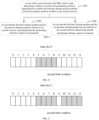
- the criterion type 3 includes a criterion that the second symbol in the second time domain position is within a second time window, in which the second time window refers to a time window corresponding to the first time domain position.
- the above second time window is a time window corresponding to the first time domain position in case that the positioning reference signal is located on another downlink bandwidth part.
- the second time window includes: symbols at the first time domain position, X2 symbols before the first time domain position, and Y2 symbols after the first time domain position, where X2 and Y2 are non-negative integers.
- the first time domain position in FIG 10 includes symbols 5-8 on a time slot 5, X2 takes a value of 0, and Y2 takes a value of 5, then the second time window includes symbols 5-13.
- the X2 symbols and the Y2 symbols are determined based on the subcarrier spacing of the initial downlink bandwidth part.
- the terminal obtains the subcarrier spacing of the initial downlink bandwidth part after determining to adopt the second criterion, or after starting the positioning function, or after starting the device itself, and the terminal determines, based on the subcarrier spacing of the initial downlink bandwidth part, the X2 symbols and the Y2 symbols and/or a symbol length of each of the X2 symbols and the Y2 symbols.
- the X2 symbols and Y2 symbols are determined based on the subcarrier spacing of the downlink bandwidth part other than the initial downlink bandwidth part, that is, determined based on the subcarrier spacing of the other downlink bandwidth part to which the positioning reference signal belongs. For example, after the terminal determines to adopt the second criterion, or after the positioning function is started, or after the device itself is started, the terminal obtains the subcarrier spacing of the other downlink bandwidth part, and determines, based on the subcarrier spacing of the other downlink bandwidth part, the X2 symbols and the Y2 symbols and/or a symbol length of each of the X2 symbols and the Y2 symbols.
- the X2 symbols and the Y2 symbols are determined based on the subcarrier spacing of the initial downlink bandwidth part and a radio frequency (RF) retuning time.
- RF radio frequency
- the terminal obtains the subcarrier spacing of the initial downlink bandwidth part and the RF retuning time, and determines, based on the subcarrier spacing of the initial downlink bandwidth part and the RF retuning time, the X2 symbols and the Y2 symbols and/or a symbol length of each of the X2 symbols and the Y2 symbols.
- the X2 symbols and the Y2 symbols are determined based on the subcarrier spacing of the other downlink bandwidth part and the RF retuning time. For example, after the terminal determines to adopt the second criterion, or after the positioning function is started, or after the device itself is started, the terminal obtains the subcarrier spacing of the other downlink bandwidth part and the RF retuning time, and determines, based on the subcarrier spacing of the other downlink bandwidth part and the RF retuning time, the X2 symbols and the Y2 symbols and/or a symbol length of each of the X2 symbols and the Y2 symbols.
- the symbol length of each of the X2 symbols and the Y2 symbols is determined based on the subcarrier spacing.
- the values of X2 and Y2 are determined based on the subcarrier spacing and the RF retuning time.
- X2 is greater than or equal to X1
- Y2 is greater than or equal to Y1.
- X1 and Y1 are used to determine the first time window corresponding to the first time domain position in case that the positioning reference signal is located on the initial downlink bandwidth part. Compared with X2 and Y2, X1 and Y1 need not to include the RF retuning time when the bandwidth part is switched.
- the terminal After determining X2 and Y2 based on any of the above four methods, the terminal reports its own capability to the access network device and/or the location server, for example, the terminal may report to the access network device and/or the location server that the second criterion is supported, and report X2 and Y2. In this way, the access network device and/or the location server can clearly know the PRS received by the terminal.
- the terminal performs steps 420 to 430 according to the determination result as follows.
- step 420 in case that the first time domain position and the second time domain position conform to the second criterion, it is determined that the positioning reference signal is not measured.
- the terminal determines not to measure the positioning reference signal. That is, if some or all of the symbols in the second time domain position are within the second time window, the terminal determines not to measure the positioning reference signal.
- the first time domain position in FIG 11 includes symbols 5-8 on a time slot 5, X2 takes a value of 0, and Y2 takes a value of 5, then the second time window includes symbols 5-13 on the time slot 5. If the second time domain position includes symbols 10-13 on the time slot 5, it is determined that the second symbol in the second time domain position is within the second time window, and the terminal determines not to measure the positioning reference signal.
- step 430 in case that the first time domain position and the second time domain position do not conform to the second criterion, it is determined that the positioning reference signal is measured.
- the terminal determines to measure the positioning reference signal. That is, if all the symbols in the second time domain position are outside the second time window, the terminal determines to measure the positioning reference signal.
- the first time domain position in FIG 12 includes symbols 5-8 on a time slot 6, the second time window includes symbols 5-13 on the time slot 6, and the second time domain position includes symbols 1-2 on the time slot 6. It is determined that the second symbol in the second time domain position is outside the second time window, and the terminal determines to measure the positioning reference signal.
- X2 and Y2 may be used to indicate the time interval threshold.
- X2 can be used to indicate the time interval threshold between the starting position of the second time domain position and the starting position of the first time domain position
- Y2 can be used to indicate the time interval threshold between the ending position of the second time domain position and the ending position of the first time domain position.
- the ending position of the second time domain position is before the starting position of the first time domain position and the time interval between the ending position of the second time domain position and the starting position of the first time domain position is greater than or equal to X2, or if the starting position of the second time domain position is after the ending position of the first time domain position and the time interval between the starting position of the second time domain position and the ending position of the first time domain position is greater than or equal to Y2, it is determined that all symbols in the second time domain position are located outside the second time window.
- the situation that the positioning reference signal is located on the downlink bandwidth part other than the initial downlink bandwidth part is considered, and then the manner of determining whether to measure the positioning reference signal is determined based on this situation.
- the manner is different from the manner corresponding to the initial downlink bandwidth, so that the measurement of the positioning reference signal is more suitable to the actual application scenario.
- the access network device and/or the location server receives the criterion reported by the terminal.
- the criterion is used to determine whether to measure the positioning reference signal according to the first time domain position of the downlink information and the second time domain position of the positioning reference signal in case that the terminal is in the RRC inactive state.
- the above criterion includes at least one of the criterion type 1 or the criterion type 2.
- the criterion type 1 includes a criterion that there is an overlap between the first symbol in the first time domain position and the second symbol in the second time domain position.
- the criterion type 2 includes a criterion that the second symbol in the second time domain position is within the first time window, in which the first time window refers to the time window corresponding to the first time domain position.
- the first time window includes: symbols at the first time domain position, X1 symbols before the first time domain position, and Y1 symbols after the first time domain position, where X1 and Y1 are non-negative integers.
- the X1 symbols and the Y1 symbols are determined based on the subcarrier spacing of the initial downlink bandwidth part. If the terminal determines X1 and Y1 based on the above subcarrier spacing, it also reports X1 and Y1 to the access network device and/or location server, and correspondingly, the access network device and/or the location server receives X1 and Y1 reported by the terminal.
- the above criterion includes the criterion type 3.
- the criterion type 3 includes a criterion that the second symbol in the second time domain position is within a second time window, in which the second time window refers to a time window corresponding to the first time domain position.
- the second time window includes: symbols at the first time domain position, X2 symbols before the first time domain position, and Y2 symbols after the first time domain position, where X2 and Y2 are non-negative integers.
- the X2 symbols and the Y2 symbols are determined based on the subcarrier spacing of the initial downlink bandwidth part. Or, the X2 symbols and the Y2 symbols are determined based on the subcarrier spacing of the downlink bandwidth part other than the initial downlink bandwidth part, that is, determined based on the subcarrier spacing of the downlink bandwidth part where the positioning reference signal is located. Or, the X2 symbols and the Y2 symbols are determined based on the subcarrier spacing of the initial downlink bandwidth part and the radio frequency retuning time.
- the X2 symbols and the Y2 symbols are determined based on the subcarrier spacing of the other downlink bandwidth part (that is, based on the subcarrier spacing of the downlink bandwidth part where the positioning reference signal is located) and the radio frequency retuning time. If the terminal determines X2 and Y2 based on the subcarrier spacing and/or the radio frequency retuning time, the terminal also reports X2 and Y2 to the access network device and/or the location server, and correspondingly, the access network device and/or the location server receives X2 and Y2 reported by the terminal.
- the access network device (mainly the access network device to which the serving cell of the terminal belongs) can determine that the terminal cannot measure the positioning reference signal based on the above terminal capability reported by the terminal or the location server, and then needs not to send the positioning reference signal.
- the access network device to which the adjacent cell of the terminal belongs does not know a sending time of the downlink information of the serving cell of the terminal, the adjacent cell will continue to send, but the terminal cannot receive it due to a conflict.
- the terminal determines the first time domain position of the downlink channel/signal and the second time domain position of the PRS, and determines whether to receive the PRS according to the criterion.
- the criterion includes at least one of the following:
- the criterion types 1 and 2 are applicable to the case that the PRS is located inside the initial DL BWP, while the criterion type 3 is applicable to the case that the PRS is located outside the initial DL BWP.
- the terminal reports the UE capability (that is, terminal capability) to at least one of LMF or gNB.
- X2 and Y2 are determined based on the SCS of the initial DL BWP or based on the SCS of the BWP where the PRS is located.
- FIG 13 is a block diagram of a signal measurement apparatus provided by an embodiment of the present invention.
- the apparatus can be implemented as part or all of the UE through software, hardware or a combination of the software and hardware.
- the apparatus includes a processing module 510.
- the processing module 510 is configured to determine whether to measure a positioning reference signal according to a first time domain position of downlink information and a second time domain position of the positioning reference signal in case that the terminal is in a radio resource control inactive state.
- the processing module 510 is configured to determine whether to measure the positioning reference signal based on whether the first time domain position and the second time domain position conform to a first criterion.
- the first criterion includes at least one of a criterion type 1 or a criterion type 2.
- the criterion type 1 includes a criterion that there is an overlap between a first symbol in the first time domain position and a second symbol in the second time domain position.
- the criterion type 2 includes a criterion that the second symbol in the second time domain position is within a first time window, in which the first time window refers to a time window corresponding to the first time domain position.
- the positioning reference signal is located on an initial downlink bandwidth part.
- the first time window includes: symbols at the first time domain position, X1 symbols before the first time domain position, and Y1 symbols after the first time domain position, where X1 and Y1 are non-negative integers.
- the X1 symbols and the Y1 symbols are determined based on a subcarrier spacing of an initial downlink bandwidth part.
- the apparatus further includes: a sending module 520.
- the sending module 520 is configured to report X1 and Y1 to an access network device and/or a location server.
- the apparatus further includes: a sending module 520.
- the sending module 520 is configured to report support for at least one of the criterion type 1 or the criterion type 2 to an access network device and/or a location server.
- the processing module 510 is configured to determine whether to measure the positioning reference signal based on whether the first time domain position and the second time domain position conform to a second criterion.
- the second criterion includes a criterion type 3, the criterion type 3 includes a criterion that a second symbol in the second time domain position is within a second time window, in which the second time window refers to a time window corresponding to the first time domain position.
- the positioning reference signal is located on a downlink bandwidth part other than an initial downlink bandwidth part.
- the second time window includes: symbols at the first time domain position, X2 symbols before the first time domain position, and Y2 symbols after the first time domain position, where X2 and Y2 are non-negative integers.
- the X2 symbols and the Y2 symbols are determined based on a subcarrier spacing of an initial downlink bandwidth part; or
- the apparatus further includes: a sending module 520.
- the sending module 520 is configured to report support for the second criterion and report X2 and Y2 to an access network device and/or a location server.
- X2 is greater than or equal to X1
- Y2 is greater than or equal to Y1
- X1 and Y1 are used for determining the first time window corresponding to the first time domain position in case that the positioning reference signal is located on an initial downlink bandwidth part.
- the processing module 510 is configured to determine not to measure the positioning reference signal in case that the first time domain position and the second time domain position conform to the first criterion.
- the processing module 510 is configured to determine to measure the positioning reference signal in case that the first time domain position and the second time domain position do not conform to the first criterion.
- the processing module 510 is configured to determine not to measure the positioning reference signal in case that the first time domain position and the second time domain position conform to the second criterion.
- the processing module 510 is configured to determine to measure the positioning reference signal in case that the first time domain position and the second time domain position do not conform to the second criterion.
- the downlink information includes at least one of the following:
- the signal measurement apparatus it can be determined, based on the first time domain position of the downlink information and the second time domain position of the positioning reference signal, whether there is a reception conflict between the downlink information and the positioning reference signal when it is in the RRC inactive state, which may provide a criterion for selecting to or not to measure the positioning reference signal, that is, whether to measure the positioning reference signal.
- Fig. 14 is a block diagram of a signal measurement apparatus provided by an embodiment of the present invention.
- the apparatus can be implemented as part or all of an access network device and/or a location server through software, hardware or a combination of the software and hardware.
- the apparatus includes a receiving module 610.
- the receiving module 610 is configured to receive a criterion reported by a terminal; in which the criterion is used for, when the terminal is in a radio resource control inactive state, determining whether to measure a positioning reference signal according to a first time domain position of downlink information and a second time domain position of the positioning reference signal.
- the criterion includes at least one of the following:
- the positioning reference signal is located on an initial downlink bandwidth part.
- the first time window includes: symbols at the first time domain position, X1 symbols before the first time domain position, and Y1 symbols after the first time domain position, where X1 and Y1 are non-negative integers.
- the X1 symbols and the Y1 symbols are determined based on a subcarrier spacing of an initial downlink bandwidth part.
- the receiving module 610 is configured to receive X1 and Y1 reported by the terminal.
- the criterion includes: a criterion type 3 comprising a criterion that a second symbol in the second time domain position is within a second time window, in which the second time window refers to a time window corresponding to the first time domain position.
- the positioning reference signal is located on a downlink bandwidth part other than an initial downlink bandwidth part.
- the second time window includes: symbols at the first time domain position, X2 symbols before the first time domain position, and Y2 symbols after the first time domain position, where X2 and Y2 are non-negative integers.
- the X2 symbols and the Y2 symbols are determined based on a subcarrier spacing of an initial downlink bandwidth part; or
- the receiving module 610 is configured to receive X2 and Y2 reported by the terminal.
- the apparatus can obtain the terminal capability and determine that the terminal cannot measure the positioning reference signal, then the positioning reference signal needs not to be sent. Since the access network device to which the adjacent cell of the terminal belongs does not know the sending time of the downlink information of the serving cell of the terminal, the adjacent cell will continue to send, but the terminal cannot receive it due to the conflict.
- FIG 15 shows a schematic diagram of a UE provided by an embodiment of the present invention.
- the UE includes: a processor 111, a receiver 112, a transmitter 113, a memory 114 and a bus 115.
- the processor 111 includes one or more processing cores, and the processor 111 executes various functional applications and information processing by running software programs and modules.
- the receiver 112 and the transmitter 113 can be implemented as a communication component, which can be a communication chip.
- the memory 114 is connected to the processor 111 through the bus 115.
- the memory 114 may be used to store at least one instruction, and the processor 111 is used to execute the at least one instruction, so as to implement steps in the foregoing method embodiments.
- the memory 114 can be implemented by any type of volatile or non-volatile storage devices or their combination.
- the volatile or non-volatile storage devices include but not limited to: magnetic or optical disks, Electrically Erasable Programmable Read Only Memory (EEPROM), Erasable Programmable Read Only Memory (EPROM), Static Random-Access Memory (SRAM), Read Only Memory (ROM), magnetic memory, flash memory, Programmable Read Only Memory (PROM).
- EEPROM Electrically Erasable Programmable Read Only Memory
- EPROM Erasable Programmable Read Only Memory
- SRAM Static Random-Access Memory
- ROM Read Only Memory
- magnetic memory magnetic memory
- flash memory Programmable Read Only Memory
- a non-transitory computer-readable storage medium including instructions, such as a memory including instructions.
- the instructions can be executed by a processor of the UE to implement the above-mentioned signal measurement method.
- the non-transitory computer-readable storage medium can be ROM, Random-Access Memory (RAM), Compact Disc Read Only Memory (CD-ROM), magnetic tape, floppy disk and optical data storage devices, etc.
- a non-transitory computer-readable storage medium is provided.
- the UE can execute the above-mentioned signal measurement method.
- Fig. 16 is a block diagram of an access network device 700 according to an embodiment.
- the access network device 700 may be a base station.
- the access network device 700 may include: a processor 701, a receiver 702, a transmitter 703 and a memory 704.
- the receiver 702, the transmitter 703 and the memory 704 are respectively connected to the processor 701 through a bus.
- the processor 701 includes one or more processing cores, and the processor 701 executes the method performed by the access network device in the signal measurement method provided by the embodiments of the present invention by running software programs and modules.
- the memory 704 can be used to store the software programs and modules. Specifically, the memory 704 may store an operating system 7041 and an application program module 7042 required by at least one function.
- the receiver 702 is used to receive communication data sent by other devices, and the transmitter 703 is used to send communication data to other devices.
- An embodiment of the present invention also provides a computer-readable storage medium.
- the computer-readable storage medium stores at least one instruction, at least one program, a code set or an instruction set, the at least one instruction, the at least one program, the code set or the instruction set is loaded and executed by a processor to implement the signal measurement method provided by the above method embodiments.
- An embodiment of the present invention also provides a computer program product.
- the computer program product includes computer instructions stored in a computer-readable storage medium.
- a processor of a computer device reads the computer instructions from the computer-readable storage medium, and executes the computer instructions, so that the computer device implements the signal measurement method provided by each method embodiment above.
- plural refers to two or more than two.
- the term “and/or” describes the association relationship of associated objects, indicating that there may be three types of relationships, for example, A and/or B may indicate: A exists alone, A and B exist simultaneously, and B exists alone.
- the character “/” generally indicates that the associated objects have an "or” relationship.
Landscapes
- Engineering & Computer Science (AREA)
- Signal Processing (AREA)
- Computer Networks & Wireless Communication (AREA)
- Physics & Mathematics (AREA)
- General Physics & Mathematics (AREA)
- Radar, Positioning & Navigation (AREA)
- Remote Sensing (AREA)
- Mobile Radio Communication Systems (AREA)
Applications Claiming Priority (2)
| Application Number | Priority Date | Filing Date | Title |
|---|---|---|---|
| CNPCT/CN2022/076225 | 2022-02-14 | ||
| PCT/CN2022/079129 WO2023151144A1 (zh) | 2022-02-14 | 2022-03-03 | 信号测量方法、装置、设备、介质及程序产品 |
Publications (2)
| Publication Number | Publication Date |
|---|---|
| EP4498741A1 true EP4498741A1 (de) | 2025-01-29 |
| EP4498741A4 EP4498741A4 (de) | 2025-07-09 |
Family
ID=82233152
Family Applications (1)
| Application Number | Title | Priority Date | Filing Date |
|---|---|---|---|
| EP22925506.2A Pending EP4498741A4 (de) | 2022-02-14 | 2022-03-03 | Signalmessverfahren und -vorrichtung sowie vorrichtung, medium und programmprodukt |
Country Status (3)
| Country | Link |
|---|---|
| US (1) | US20250159646A1 (de) |
| EP (1) | EP4498741A4 (de) |
| CN (1) | CN114731263B (de) |
Families Citing this family (1)
| Publication number | Priority date | Publication date | Assignee | Title |
|---|---|---|---|---|
| CN120321761A (zh) * | 2024-01-15 | 2025-07-15 | 华为技术有限公司 | 信号校验的方法及装置 |
Family Cites Families (4)
| Publication number | Priority date | Publication date | Assignee | Title |
|---|---|---|---|---|
| CN107734635B (zh) * | 2016-08-12 | 2021-06-08 | 中兴通讯股份有限公司 | 一种信号接收方法、装置及终端 |
| US11129195B2 (en) * | 2017-08-09 | 2021-09-21 | Qualcomm Incorporated | Techniques and apparatuses for positioning reference signal (PRS) management |
| CN113660730B (zh) * | 2020-05-12 | 2024-01-12 | 大唐移动通信设备有限公司 | 一种碰撞处理、指示方法及设备、装置、介质 |
| CN112039645B (zh) * | 2020-08-07 | 2023-12-22 | 中国信息通信研究院 | 一种定位导频优先级指示方法和设备 |
-
2022
- 2022-03-03 EP EP22925506.2A patent/EP4498741A4/de active Pending
- 2022-03-03 CN CN202280000701.8A patent/CN114731263B/zh active Active
- 2022-03-03 US US18/838,183 patent/US20250159646A1/en active Pending
Also Published As
| Publication number | Publication date |
|---|---|
| CN114731263A (zh) | 2022-07-08 |
| EP4498741A4 (de) | 2025-07-09 |
| CN114731263B (zh) | 2025-06-06 |
| US20250159646A1 (en) | 2025-05-15 |
Similar Documents
| Publication | Publication Date | Title |
|---|---|---|
| US12010728B2 (en) | Random access method and device | |
| US20230062230A1 (en) | Resource determination method and apparatus, and device and storage medium | |
| JP7612012B2 (ja) | セカンダリセルをアクティブ化する方法、装置、デバイス及び記憶媒体 | |
| RU2743486C1 (ru) | Способ и устройство беспроводной связи | |
| US20250097777A1 (en) | Cell access method and apparatus, and device and readable storage medium | |
| US20230292281A1 (en) | Positioning method | |
| US20230354286A1 (en) | Communication method, access network device, and terminal | |
| WO2021189254A1 (en) | Method and apparatus for sidelink resource re-evaluation | |
| US20230388960A1 (en) | Reference signal transmission method, apparatus and device, and readable storage medium | |
| US12568532B2 (en) | Method for random access resource determination, network device, and storage medium | |
| US20230057174A1 (en) | Method and apparatus for beam-based transmission for sidelink | |
| RU2493680C1 (ru) | Пользовательское устройство и способ мобильной связи | |
| EP4518550A1 (de) | Direktzugriffsressourcenkonfigurationsverfahren, direktzugriffsverfahren, vorrichtung und speichermedium | |
| EP4498741A1 (de) | Signalmessverfahren und -vorrichtung sowie vorrichtung, medium und programmprodukt | |
| CN114449571B (zh) | 强干扰条件下配置小区接入资源的方法及装置 | |
| US20250159537A1 (en) | Measurement method and terminal | |
| CN116569636B (zh) | 小数据传输方法、装置、设备及介质 | |
| CN115443615B (zh) | 用于pucch和pusch的发射器波束选择 | |
| US12414081B2 (en) | Method for determining resource location, communication device, and non-transitory computer-readable medium | |
| US20230371041A1 (en) | Receiving method and apparatus, terminal device, and storage medium | |
| WO2023151144A1 (zh) | 信号测量方法、装置、设备、介质及程序产品 | |
| RU2857768C2 (ru) | Способ и устройство для приема блока сигналов синхронизации, способ и устройство для передачи блока сигналов синхронизации, носитель информации и продукт | |
| KR20210022633A (ko) | 무선 링크 모니터링의 방법과 단말 장치 | |
| RU2814209C1 (ru) | Способ и устройство приема, терминальное устройство и носитель данных | |
| WO2025065612A1 (en) | Systems and methods for physical random access channel (prach) enhancement |
Legal Events
| Date | Code | Title | Description |
|---|---|---|---|
| STAA | Information on the status of an ep patent application or granted ep patent |
Free format text: STATUS: THE INTERNATIONAL PUBLICATION HAS BEEN MADE |
|
| PUAI | Public reference made under article 153(3) epc to a published international application that has entered the european phase |
Free format text: ORIGINAL CODE: 0009012 |
|
| STAA | Information on the status of an ep patent application or granted ep patent |
Free format text: STATUS: REQUEST FOR EXAMINATION WAS MADE |
|
| 17P | Request for examination filed |
Effective date: 20240912 |
|
| AK | Designated contracting states |
Kind code of ref document: A1 Designated state(s): AL AT BE BG CH CY CZ DE DK EE ES FI FR GB GR HR HU IE IS IT LI LT LU LV MC MK MT NL NO PL PT RO RS SE SI SK SM TR |
|
| DAV | Request for validation of the european patent (deleted) | ||
| DAX | Request for extension of the european patent (deleted) | ||
| A4 | Supplementary search report drawn up and despatched |
Effective date: 20250605 |
|
| RIC1 | Information provided on ipc code assigned before grant |
Ipc: H04W 88/18 20090101ALI20250530BHEP Ipc: H04W 24/10 20090101ALI20250530BHEP Ipc: H04W 64/00 20090101ALI20250530BHEP Ipc: H04W 72/00 20230101AFI20250530BHEP |