EP4498598A1 - Installation structure for photovoltaic sheet - Google Patents
Installation structure for photovoltaic sheet Download PDFInfo
- Publication number
- EP4498598A1 EP4498598A1 EP23774999.9A EP23774999A EP4498598A1 EP 4498598 A1 EP4498598 A1 EP 4498598A1 EP 23774999 A EP23774999 A EP 23774999A EP 4498598 A1 EP4498598 A1 EP 4498598A1
- Authority
- EP
- European Patent Office
- Prior art keywords
- power generation
- photovoltaic power
- generation sheet
- installation surface
- sheet
- Prior art date
- Legal status (The legal status is an assumption and is not a legal conclusion. Google has not performed a legal analysis and makes no representation as to the accuracy of the status listed.)
- Pending
Links
Images










Classifications
-
- H—ELECTRICITY
- H02—GENERATION; CONVERSION OR DISTRIBUTION OF ELECTRIC POWER
- H02S—GENERATION OF ELECTRIC POWER BY CONVERSION OF INFRARED RADIATION, VISIBLE LIGHT OR ULTRAVIOLET LIGHT, e.g. USING PHOTOVOLTAIC [PV] MODULES
- H02S20/00—Supporting structures for PV modules
- H02S20/20—Supporting structures directly fixed to an immovable object
- H02S20/22—Supporting structures directly fixed to an immovable object specially adapted for buildings
-
- H—ELECTRICITY
- H10—SEMICONDUCTOR DEVICES; ELECTRIC SOLID-STATE DEVICES NOT OTHERWISE PROVIDED FOR
- H10F—INORGANIC SEMICONDUCTOR DEVICES SENSITIVE TO INFRARED RADIATION, LIGHT, ELECTROMAGNETIC RADIATION OF SHORTER WAVELENGTH OR CORPUSCULAR RADIATION
- H10F19/00—Integrated devices, or assemblies of multiple devices, comprising at least one photovoltaic cell covered by group H10F10/00, e.g. photovoltaic modules
- H10F19/80—Encapsulations or containers for integrated devices, or assemblies of multiple devices, having photovoltaic cells
- H10F19/804—Materials of encapsulations
-
- H—ELECTRICITY
- H02—GENERATION; CONVERSION OR DISTRIBUTION OF ELECTRIC POWER
- H02S—GENERATION OF ELECTRIC POWER BY CONVERSION OF INFRARED RADIATION, VISIBLE LIGHT OR ULTRAVIOLET LIGHT, e.g. USING PHOTOVOLTAIC [PV] MODULES
- H02S20/00—Supporting structures for PV modules
- H02S20/20—Supporting structures directly fixed to an immovable object
- H02S20/22—Supporting structures directly fixed to an immovable object specially adapted for buildings
- H02S20/23—Supporting structures directly fixed to an immovable object specially adapted for buildings specially adapted for roof structures
-
- H—ELECTRICITY
- H02—GENERATION; CONVERSION OR DISTRIBUTION OF ELECTRIC POWER
- H02S—GENERATION OF ELECTRIC POWER BY CONVERSION OF INFRARED RADIATION, VISIBLE LIGHT OR ULTRAVIOLET LIGHT, e.g. USING PHOTOVOLTAIC [PV] MODULES
- H02S30/00—Structural details of PV modules other than those related to light conversion
-
- H—ELECTRICITY
- H02—GENERATION; CONVERSION OR DISTRIBUTION OF ELECTRIC POWER
- H02S—GENERATION OF ELECTRIC POWER BY CONVERSION OF INFRARED RADIATION, VISIBLE LIGHT OR ULTRAVIOLET LIGHT, e.g. USING PHOTOVOLTAIC [PV] MODULES
- H02S30/00—Structural details of PV modules other than those related to light conversion
- H02S30/20—Collapsible or foldable PV modules
-
- H—ELECTRICITY
- H10—SEMICONDUCTOR DEVICES; ELECTRIC SOLID-STATE DEVICES NOT OTHERWISE PROVIDED FOR
- H10F—INORGANIC SEMICONDUCTOR DEVICES SENSITIVE TO INFRARED RADIATION, LIGHT, ELECTROMAGNETIC RADIATION OF SHORTER WAVELENGTH OR CORPUSCULAR RADIATION
- H10F19/00—Integrated devices, or assemblies of multiple devices, comprising at least one photovoltaic cell covered by group H10F10/00, e.g. photovoltaic modules
- H10F19/80—Encapsulations or containers for integrated devices, or assemblies of multiple devices, having photovoltaic cells
-
- Y—GENERAL TAGGING OF NEW TECHNOLOGICAL DEVELOPMENTS; GENERAL TAGGING OF CROSS-SECTIONAL TECHNOLOGIES SPANNING OVER SEVERAL SECTIONS OF THE IPC; TECHNICAL SUBJECTS COVERED BY FORMER USPC CROSS-REFERENCE ART COLLECTIONS [XRACs] AND DIGESTS
- Y02—TECHNOLOGIES OR APPLICATIONS FOR MITIGATION OR ADAPTATION AGAINST CLIMATE CHANGE
- Y02E—REDUCTION OF GREENHOUSE GAS [GHG] EMISSIONS, RELATED TO ENERGY GENERATION, TRANSMISSION OR DISTRIBUTION
- Y02E10/00—Energy generation through renewable energy sources
- Y02E10/50—Photovoltaic [PV] energy
Definitions
- the present disclosure relates to an installation structure for a photovoltaic power generation sheet in which a photovoltaic power generation sheet is installed above an installation surface.
- a photovoltaic power generation sheet of this type can adjust an installation angle with respect to sunlight by its own flexibility and is lightweight at the same time, and thus it is expected that the photovoltaic power generation sheet is directly installed on an installation surface without using an attachment base.
- a gap 103 is generated between the photovoltaic power generation sheet 100 and the installation surface 102.
- the photovoltaic power generation sheet 100 vibrates and the incident angle of sunlight on the photovoltaic power generation sheet 100 becomes unstable, and therefore the power generation efficiency of the photovoltaic power generation sheet is reduced.
- the photovoltaic power generation sheet is lightweight and does not cause a problem of a case where a rigid solar cell is increased in size, an increase in size has been studied.
- the size of the photovoltaic power generation sheet is increased, the above-described vibration due to the influence of wind becomes large, and the problem of the decrease in power generation efficiency due to the vibration becomes remarkable. This problem is unique to the photovoltaic power generation sheet.
- the present disclosure has been made in view of the above matters, and an object of the present disclosure is to provide an installation structure for a photovoltaic power generation sheet that can suppresses vibration of the photovoltaic power generation sheet due to wind in a state where the photovoltaic power generation sheet is installed above an installation surface.
- the present disclosure includes, as a subject, an installation structure for a photovoltaic power generation sheet according to the following item 1.
- An installation structure for a photovoltaic power generation sheet including:
- the present disclosure includes the installation structure for the photovoltaic power generation sheet according to the following item 2 as a preferable aspect of the installation structure for the photovoltaic power generation sheet according to the above item 1.
- Item 2 The installation structure to item 1, wherein the sealing member is formed of a bonder provided between at least an outer peripheral portion of the photovoltaic power generation sheet and the installation surface to bond the outer peripheral portion to the installation surface.
- the present disclosure includes the installation structure for the photovoltaic power generation sheet according to the following item 3 as a preferable aspect of the installation structure for the photovoltaic power generation sheet according to the above item 2.
- Item 3 The installation structure according to item 2, wherein the bonder has a loss factor of 0.01 or more and 0.3 or less.
- the present disclosure includes the installation structure for the photovoltaic power generation sheet according to the following item 4 as a preferable aspect of the installation structure for the photovoltaic power generation sheet according to the above item 3.
- Item 4 The installation structure for the installation structure for a photovoltaic power generation sheet according to item 3, wherein the bonder has a thickness of 3 mm or more and 20 mm or less.
- the present disclosure includes the installation structure for the photovoltaic power generation sheet according to the following item 5 as a preferable aspect of the installation structure for the photovoltaic power generation sheet according to the above items 2 to 4.
- Item 5 The installation structure according to any one of items 2 to 4, wherein the bonder has a modulus of transverse elasticity of 0.1 MPa or more and 100 MPa or less.
- the present disclosure includes the installation structure for the photovoltaic power generation sheet according to the following item 6 as a preferable aspect of the installation structure for the photovoltaic power generation sheet according to the above items 2 to 5.
- Item 6 The installation structure according to any one of items 2 to 5, wherein the bonder has a viscosity of 800cP or more.
- the present disclosure includes the installation structure for the photovoltaic power generation sheet according to the following item 7 as a preferable aspect of the installation structure for the photovoltaic power generation sheet according to the above items 2 to 6.
- Item 7 The installation structure according to any one of items 2 to 6, wherein the bonder includes at least one or more resin compositions selected from a vinyl acetate resin, an ethylene vinyl acetate resin, an epoxy resin, a cyanoacrylate resin, an acrylic resin, a chloroprene rubber, styrene, a butadiene rubber, a polyurethane resin, a silicone resin, and a modified silicone resin.
- the bonder includes at least one or more resin compositions selected from a vinyl acetate resin, an ethylene vinyl acetate resin, an epoxy resin, a cyanoacrylate resin, an acrylic resin, a chloroprene rubber, styrene, a butadiene rubber, a polyurethane resin, a silicone resin, and a modified silicone resin.
- the present disclosure includes the installation structure for the photovoltaic power generation sheet according to the following item 8 as a preferable aspect of the installation structure for the photovoltaic power generation sheet according to the above items 2 to 7.
- Item 8 The installation structure according to any one of items 2 to 7, wherein the bonder is provided between the entire photovoltaic power generation sheet and the installation surface.
- the present disclosure includes the installation structure for the photovoltaic power generation sheet according to the following item 9 as a preferable aspect of the installation structure for the photovoltaic power generation sheet according to the above items 2 to 8.
- Item 9 The installation structure according to any one of items 2 to 8, further including:
- the present disclosure includes the installation structure for the photovoltaic power generation sheet according to the following item 10 as a preferable aspect of the installation structure for the photovoltaic power generation sheet according to the above item 9.
- Item 10 The installation structure according to item 9, wherein the cover member includes a covered portion that covers a portion having a predetermined width from an outer peripheral edge on a front surface of the photovoltaic power generation sheet.
- the present disclosure includes the installation structure for the photovoltaic power generation sheet according to the following item 11 as a preferable aspect of the installation structure for the photovoltaic power generation sheet according to the above item 1.
- Item 11 The installation structure according to item 1, wherein the sealing member includes a cover member that covers a gap between an outer peripheral edge of the photovoltaic power generation sheet and the installation surface.
- the present disclosure includes the installation structure for the photovoltaic power generation sheet according to the following item 12 as a preferable aspect of the installation structure for the photovoltaic power generation sheet according to the above item 1.
- Item 12 The installation structure according to item 1, wherein the sealing member is formed of a joint material filled in a gap between at least an outer peripheral portion of the photovoltaic power generation sheet and the installation surface.
- the present disclosure includes the installation structure for the photovoltaic power generation sheet according to the following item 13 as a preferable aspect of the installation structure for the photovoltaic power generation sheet according to the above items 1 to 12.
- Item 13 The installation structure according to any one of items 1 to 12, wherein the photovoltaic power generation sheet is flexible.
- the installation structure for the photovoltaic power generation sheet of the present disclosure it is possible to suppress vibration of the photovoltaic power generation sheet due to wind in a state where the photovoltaic power generation sheet is installed above the installation surface.
- Figs. 1 and 2 illustrate an installation structure 2 for a photovoltaic power generation sheet according to a first embodiment of the present disclosure.
- the installation structure 2 includes an installation surface 3, a photovoltaic power generation sheet 1 installed above the installation surface 3, and a bonder 4 for fixing the photovoltaic power generation sheet 1 to the installation surface 3.
- the bonder 4 also functions as a sealing member for closing a gap between the outer peripheral edge of the photovoltaic power generation sheet 1 and the installation surface 3.
- the installation surface 3 is a surface of the installation object of the photovoltaic power generation sheet 1, and is configured by, for example, a surface of the building material 5.
- the building material 5 include a roof material, a wall material (metal-based siding material, ceramic-based siding material, sandwich panel, and the like), a partition, a door material, a fence material, and a floor material.
- the roof member include roof members used for a folded plate roof, a slate roof, a roof deck, a shingled bar-laid roof, an upright flat laid roof, and the like.
- the roof may be a vertical roof or a horizontal roof.
- the building material 5 may be used for a non-residential building or may be used for a residential building.
- the non-residential building is not particularly limited, and examples thereof include a store, a warehouse, a factory, a vinyl house, a greenhouse, a meeting place, a gymnasium, and a parking lot.
- the installation surface 3 may be constituted by a surface of another structure, for example, a surface of a road, a ground, an embankment, or the like, or may be constituted by a surface of an automobile, a train, a ship, or the like.
- the installation surface 3 is formed of, for example, metal, resin, asphalt, concrete, or the like.
- the installation surface 3 may be a surface on which, for example, soil, sand, gravel, or the like is deposited.
- the installation surface 3 may include a surface of a sheet member such as a resin sheet laid and fixed on the surface of the structure described above.
- the installation surface 3 may be a horizontal plane perpendicular to the direction in which gravity acts, or may be a plane intersecting the horizontal plane at an angle.
- the installation surface 3 intersecting the horizontal plane at an angle includes an inclined surface forming a predetermined inclination angle ⁇ (0° ⁇ ⁇ ⁇ 90°) with respect to the horizontal plane and a vertical plane perpendicular to the horizontal plane.
- the installation surface 3 is a horizontal plane.
- the installation surface 3 may be a flat surface or a curved surface, and its surface state may be smooth or uneven such as rough.
- the installation surface 3 may be a corrugated surface in which a plurality of crest portions and a plurality of valley portions are bent in such a manner of being alternately arranged.
- the upper limit of the arithmetic average roughness measured in JIS B0601 of the installation surface 3 is preferably 5 mm or less, more preferably 1 mm or less, and more preferably 0.5 mm or less, and the lower limit of the arithmetic average roughness measured in JIS B0601 of the installation surface 3 is 0.1 ⁇ m or more, more preferably 10 ⁇ m or more, and more preferably 100 ⁇ m or more.
- the surface roughness of the installation surface 3 is in the above range, it is possible to suppress wind from blowing from the outer peripheral edge of the photovoltaic power generation sheet 1 to between the photovoltaic power generation sheet 1 and the installation surface 3.
- the bonding force of a bonder 4 is increased by the anchor effect caused by the bonder 4 entering the unevenness of the installation surface 3, and the fixing force of the photovoltaic power generation sheet 1 to the installation surface 3 can be increased.
- the photovoltaic power generation sheet 1 is formed in a sheet shape, and generates power when at least one surface (for example, a front surface) in a thickness direction receives sunlight.
- sheet shape refers to a shape in which the thickness of the object is 10% or less with respect to the maximum length between the outer edges in plan view.
- maximum length between the outer edges in plan view refers to a length of a diagonal line.
- maximum length between the outer edges in plan view refers to the length of the diameter.
- a film shape, a foil shape, a film shape, and the like are also included in the "sheet shape”.
- the photovoltaic power generation sheet 1 is formed in a substantially rectangular shape in plan view.
- the shape of the photovoltaic power generation sheet 1 is not limited to a substantially rectangular shape in plan view, and may be, for example, a substantially circular shape in plan view, an elliptical shape in plan view, a polygonal shape in plan view, or the like.
- the photovoltaic power generation sheet 1 is flexible.
- the lower limit of the flexural strength of the photovoltaic power generation sheet 1 is preferably 10 MPa or more, more preferably 50 MPa or more, and more preferably 100 MPa or more
- the upper limit of the flexural strength of the photovoltaic power generation sheet 1 is preferably 200 MPa or less, more preferably 150 MPa or less, and more preferably 130 MPa or less.
- the flexibility of the photovoltaic power generation sheet 1 may be defined by a flexural modulus.
- the lower limit of the flexural modulus of the photovoltaic power generation sheet 1 is preferably 100 MPa or more, more preferably 500 MPa or more, and the upper limit of the flexural modulus of the photovoltaic power generation sheet 1 is preferably 10,000 MPa or less, more preferably 5000 MPa or less.
- the flexural strength may not be included in the above range. Since the flexural strength or the flexural modulus of the photovoltaic power generation sheet 1 is set within the above range, it is possible to suppress occurrence of breakage such as cracking while making construction favorably.
- the flexural strength and the flexural modulus of the photovoltaic power generation sheet 1 are measured by, for example, a measurement method in accordance with JIS K7171.
- the photovoltaic power generation sheet 1 includes a back sheet 6, a power generator 7, a barrier sheet 8, a sealant 9, and a sealing edge member 10.
- the power generator 7 and the sealant 9 are disposed between the back sheet 6 and the barrier sheet 8.
- the sealing edge member 10 seals between the outer peripheral edge of the back sheet 6 and the outer peripheral edge of the barrier sheet 8.
- the back sheet 6 is disposed on a side opposite to the light receiving surface of the photovoltaic power generation sheet 1.
- the back sheet 6 constitutes a surface of the photovoltaic power generation sheet 1 facing the installation surface 3 ( Figs. 1 and 2 ).
- the back sheet 6 has barrier performance against water vapor and protection performance against external force.
- the back sheet 6 may be translucent, and does not necessarily need to be translucent.
- be translucent refers to a light transmittance of 10% or more with respect to the peak wavelength of light prior to incidence.
- the lower limit of the thickness of the back sheet 6 is preferably 50 ⁇ m or more, more preferably 100 ⁇ m or more, and more preferably 200 ⁇ m or more, and the upper limit of the thickness of the back sheet 6 is preferably 2000 ⁇ m, more preferably 1000 ⁇ m or less, more preferably 800 ⁇ m or less, and more preferably 600 ⁇ m or less.
- the thickness of the back sheet 6 is in the above range, the flexural strength of the photovoltaic power generation sheet 1 can be easily set in the above range.
- the power generator 7 includes a power generation cell 70 which is a photoelectric conversion element using a photovoltaic effect.
- the power generator 7 includes a photoelectric conversion unit in which a plurality of power generation cells 70 are arranged in a surface direction of the photovoltaic power generation sheet 1 (for example, a longitudinal direction and/or a width direction of the photovoltaic power generation sheet 1). Note that the power generator 7 may be configured by one power generation cell 70.
- the power generation cell 70 includes a translucent base member 11, a translucent conductive layer 12, a power generation layer 13, and an electrode 14.
- the translucent base member 11, the translucent conductive layer 12, the power generation layer 13, and the electrode 14 are stacked in this order in a direction from the barrier sheet 8 toward the back sheet 6. That is, the translucent base member 11 is disposed in a manner of facing the barrier sheet 8, and the electrode 14 is disposed in a manner of facing the back sheet 6.
- the translucent base member 11 supports the translucent conductive layer 12, the power generation layer 13, and the electrode 14.
- the translucent base member 11 is translucent.
- the light transmittance is 10% or more with respect to the peak wavelength of light prior to incidence., and is preferably 50% or more, more preferably 80% or more.
- "transparent” is defined as having a light transmittance of 80% or more with respect to the peak wavelength of light prior to incidence.
- Examples of the material of the translucent base member 11 include an inorganic material, an organic material, and a metal material.
- the inorganic material include quartz glass and alkali-free glass.
- Examples of the organic material include polyethylene terephthalate (PET), polyethylene naphthalene (PEN), polyethylene, polyimide, polyamide, polyamideimide, liquid crystal polymers, cyclo-olefin polymers, and other plastics and polymer films.
- Examples of the metal material include stainless steel, aluminum, titanium, and silicon.
- the thickness of the translucent base member 11 is not particularly limited as long as the translucent base member 11 can support the translucent conductive layer 12, the power generation layer 13, and the electrode 14, and the thickness of the translucent base member 11 is, for example, 30 ⁇ m or more and 300 ⁇ m or less.
- the translucent base member 11 is a base member required in the manufacturing process of the power generation cell 70.
- the translucent base member 11 is not necessarily required, and for example, may be used only during the manufacturing of the photovoltaic power generation sheet 1, or may be removed after or during the manufacturing. When removed, a base member that is not translucent may be used instead of the translucent base member 11.
- the translucent conductive layer 12 is a layer that is conductive and functions as a cathode.
- the translucent conductive layer 12 is translucent.
- the translucent conductive layer 12 is preferably transparent.
- Examples of the translucent conductive layer 12 include indium tin oxide (ITO), fluorine-doped tin oxide (FTO), nesa films, and other transparent materials.
- the translucent conductive layer 12 is formed on the surface of a translucent substrate by, for example, a sputtering method, an ion plating method, a plating method, a coating method, or the like.
- the translucent conductive layer 12 may be configured to be translucent by forming a pattern capable of transmitting light while using a material that is not translucent.
- the material that is not translucent include platinum, gold, silver, copper, aluminum, rhodium, indium, titanium, nickel, tin, zinc, and alloys containing these metals.
- the pattern capable of transmitting light include a lattice shape, a linear shape, a wavy line shape, a honeycomb shape, and a round hole shape.
- the thickness of the translucent conductive layer 12 is preferably, for example, 30 nm or more and 300 nm or less. When the thickness of the translucent conductive layer 12 is 30 nm or more and 300 nm or less, excellent conductivity can be obtained while maintaining high flexibility.
- the power generation layer 13 is a layer that causes photoelectric conversion by light irradiation, producing electrons and holes from excitons generated by light absorption. As illustrated in Fig. 3(B) , the power generation layer 13 includes a hole transport layer 131, a photoelectric conversion layer 132, and an electron transport layer 133. The hole transport layer 131, the photoelectric conversion layer 132, and the electron transport layer 133 are stacked in this order in a direction from the translucent conductive layer 12 toward the electrode 14.
- the hole transport layer 131 extracts holes generated in the photoelectric conversion layer 132 to the translucent conductive layer 12, and prevents electrons generated in the photoelectric conversion layer 132 from moving to the translucent conductive layer 12.
- a metal oxide can be used as a material of the hole transport layer 131.
- the metal oxide include titanium oxide, molybdenum oxide, vanadium oxide, zinc oxide, nickel oxide, lithium oxide, calcium oxide, cesium oxide, and aluminum oxide.
- a delafosite-type compound semiconductor (CuGaO 2 ), copper oxide, copper thiocyanate (CuSCN), vanadium pentoxide (V 2 O 5 ), graphene oxide, or the like may be used.
- a p-type organic semiconductor or a p-type inorganic semiconductor can also be used as a material of the hole transport layer 131.
- the lower limit of the thickness of the hole transport layer 131 is preferably 1 nm or more and more preferably 10 nm or more, and the upper limit of the thickness of the hole transport layer 131 is preferably 1000 nm or less, more preferably 500 nm or less, and more preferably 50 nm or less. As long as the thickness of the hole transport layer 131 is in the above range, hole transport can be realized.
- the photoelectric conversion layer 132 (photoactive layer) is a layer that photoelectrically converts absorbed light.
- the material of the photoelectric conversion layer 132 is not particularly limited as long as the photoelectric conversion layer 132 can photoelectrically convert absorbed light, and for example, amorphous silicon, perovskite, a non-silicon-based material (semiconductor material CIGS), or the like is used.
- the photoelectric conversion layer 132 may have a tandem stacked structure that composites these materials.
- a semiconductor material CIGS containing copper (Cu), indium (In), gallium (Ga), and selenium (Se) is used, and the thickness of the photoelectric conversion layer is easily reduced.
- the photoelectric conversion layer 132 containing a perovskite compound has an advantage that dependence of power generation efficiency on an angle of incident light (hereinafter, there may be referred to as dependence on the incident angle) is relatively low.
- dependence on the incident angle there may be referred to as dependence on the incident angle
- the photovoltaic power generation sheet 1 since the photovoltaic power generation sheet 1 has less dependency on the gradient of the installation surface 3, the photovoltaic power generation sheet 1 can be installed in a broader location as compared with that in other solar cells, and higher power generation efficiency can be obtained.
- the perovskite compound is a structure having a perovskite crystal structure and a crystal similar thereto.
- the perovskite crystal structure is represented by the composition formula ABX 3 .
- A represents an organic cation
- B represents a metal cation
- X represents a halogen anion.
- the A site, the B site, and the X site are not limited thereto.
- the organic group of the organic cation of the A site is not particularly limited, and examples thereof include alkylammonium derivatives and formamidinium derivatives.
- the organic cation of the A site may be one kind or two or more kinds.
- the metal of the metal cation of the B site is not particularly limited, and examples thereof include Cu, Ni, Mn, Fe, Co, Pd, Ge, Sn, Pb, and Eu.
- the metal cation of the B site may be one kind or two or more kinds.
- the halogen of the halogen anion of the X site is not particularly limited, and examples thereof include F, Cl, Br, and I.
- the halogen anion of the X site may be one kind or two or more kinds.
- the lower limit of the thickness of the photoelectric conversion layer 132 is preferably 1 nm or more, more preferably 5 nm or more, more preferably 10 nm or more, more preferably 100 nm or more, and more preferably 300 nm or more, and the upper limit of the thickness of the photoelectric conversion layer 132 is preferably 1 million nm or less, more preferably 50,000 nm or less, and more preferably 1000 nm or less. As long as the thickness of the photoelectric conversion layer 132 is in the above range, the photoelectric conversion efficiency is improved.
- the electron transport layer 133 extracts electrons generated in the photoelectric conversion layer 132 to the electrode 14, and prevents holes generated in the photoelectric conversion layer 132 from moving to the electrode 14.
- the electron transport layer 133 preferably contains, for example, either a halogen compound or a metal oxide.
- halogen compound examples include lithium halide (LiF, LiCl, LiBr, LiI) and sodium halide (NaF, NaCl, NaBr, NaI).
- element of the metal oxide examples include titanium, molybdenum, vanadium, zinc, nickel, lithium, potassium, cesium, aluminum, niobium, tin, and barium.
- an n-type organic semiconductor or an n-type inorganic semiconductor can also be used as a material of the electron transport layer 133.
- the lower limit of the thickness of the electron transport layer 133 is preferably 1 nm or more and more preferably 10 nm or more, and the upper limit of the thickness of the electron transport layer 133 is preferably 1000 nm or less, more preferably 500 nm or less, and more preferably 50 nm or less. As long as the thickness of the electron transport layer 133 is in the above range, electron transport can be realized.
- the electrode 14 is conductive and functions as an anode.
- the electrode 14 can extract electrons from the photoelectric conversion layer 132 according to photoelectric conversion generated by the photoelectric conversion layer 132.
- the electrode 14 may be translucent or may be made of a material that is not translucent. Examples of the material of the electrode 14 include platinum, gold, silver, copper, aluminum, rhodium, indium, titanium, nickel, tin, zinc, and alloys containing these metals.
- the barrier sheet 8 is disposed on a side opposite to the back sheet 6 in the thickness direction of the photovoltaic power generation sheet 1.
- the barrier sheet 8 includes a light receiving surface of the photovoltaic power generation sheet 1.
- the barrier sheet 8 is translucent.
- the barrier sheet 8 is preferably transparent.
- the barrier sheet 8 has barrier performance against water vapor and protection performance against external force.
- the barrier sheet 8 is flexible.
- the lower limit of the modulus of longitudinal elasticity of the barrier sheet 8 is preferably 100 Pa or more, more preferably 1000 MPa or more, more preferably 2400 MPa or more, and more preferably 3000 MPa or more
- the upper limit of the modulus of longitudinal elasticity of the barrier sheet 8 is preferably 10,000 MPa or less, more preferably 5000 MPa or less, more preferably 4200 MPa or less, and more preferably 4000 MPa or less.
- the material of the barrier sheet 8 include a plastic film and a vinyl film made of a synthetic resin such as a thermoplastic resin, a thermosetting resin, a general-purpose plastic, an engineering plastic, and a vinyl resin (for example, polyvinyl chloride).
- a material of the barrier sheet 17 for example, a natural resin, rubber, metal, pulp, or the like may be used in addition to a synthetic resin.
- the lower limit of the thickness of the barrier sheet 8 is preferably 50 ⁇ m or more, more preferably 100 ⁇ m or more, and more preferably 200 ⁇ m or more, and the upper limit of the thickness of the barrier sheet 8 is preferably 2000 ⁇ m or less, more preferably 1000 ⁇ m or less, more preferably 800 ⁇ m or less, and more preferably 600 ⁇ m or less.
- the thickness of the barrier sheet 8 is in the above range, the flexural strength of the photovoltaic power generation sheet 1 can be easily set in the above range.
- the sealant 9 is filled between the barrier sheet 8 and the back sheet 6 in a state where the power generation layer 13 is disposed between the barrier sheet 8 and the back sheet 6.
- the sealant 9 prevents water from entering the power generation layer 13 from around the power generation layer 13.
- the sealant 9 is translucent and is preferably transparent.
- Examples of the material of the sealant 9 include ethylene vinyl acetate (EVA), polyolefin, butyl rubber, silicone resin, polyvinyl butyral, acrylic resin, polyisobutylene resin, SBS resin, SIBS resin, epoxy resin, and the like.
- EVA ethylene vinyl acetate
- the sealing edge member 10 seals the entire circumference between the outer peripheral edge of the back sheet 6 and the outer peripheral edge of the barrier sheet 8 in a state where a plurality of power generation cells 70 and the sealant 9 are disposed between the back sheet 6 and the barrier sheet 8.
- the outer peripheral edge of the sealing edge member 10 constitutes the outer peripheral edge of the photovoltaic power generation sheet 1.
- the sealing edge member 10 includes a first bonding portion 101, a second bonding portion 102, and a sealing portion 103 connecting the first bonding portion 101 and the second bonding portion 102.
- the first bonding portion 101 is bonded to a front surface (upper surface in the drawing) of the barrier sheet 8.
- the second bonding portion 102 is bonded to a back surface (lower surface in the drawing) of the back sheet 6.
- the first bonding portion 101, the sealing portion 103, and the second bonding portion 102 are integrally formed.
- Examples of the material of the sealing edge member 10 include a tape material made of butyl rubber, silicone rubber, or the like.
- the photoelectric conversion layer 132 of the power generation layer 13 absorbs light and performs photoelectric conversion, so that electrons and holes are generated in the photoelectric conversion layer 132.
- the electrons are extracted to the electrode 14 (anode) via the electron transport layer 133 and holes are extracted to the translucent conductive layer 12 (cathode) via the hole transport layer 131, a current flows from the translucent conductive layer 12 to the electrode 14 (that is, power generation is performed).
- an extension portion 14a is provided in the electrode 14 (anode) of each power generation cell 70 ( Fig. 3(C) ).
- the extension portion 14a of the electrode 14 extends toward the translucent conductive layer 12 (cathode) side.
- the extension portion 14 of the electrode 14 of one cell 70 is joined to the translucent conductive layer 12 of the other cell 70.
- a current flows from the translucent conductive layer 12A at one side end of the power generator 7 (photoelectric conversion unit) to the electrode 14A at the other side end of the power generator 7 (the flow of the current is indicated by an arrow in Fig. 3(C) ).
- the current is extracted via a power distribution line.
- the power generator 7 is configured by the photoelectric conversion unit described above, when a failure occurs in some of the power generation cells 70, the amount of electricity extracted from the power generator 7 can still be stabilized.
- an extension portion extending toward the electrode 14 (anode) side may be provided on the translucent conductive layer 12 (cathode) of each power generation cell 70.
- the extension portion of the translucent conductive layer 12 of one cell 70 is joined to the electrode 14 of the other cell 70. In this case, the same effect as described above can still be obtained.
- the translucent base member 11 is provided in the power generator 7, it is preferable to support the translucent conductive layer 12, the power generation layer 13, and the electrode 14 of each power generation cell 70 on the common translucent base member 11 as illustrated in Fig. 3(C) from the viewpoint of facilitating the manufacturing of the power generator 7.
- the current flowing from the electrode 14 to the translucent conductive layer 12 is extracted via a power distribution line.
- the photovoltaic power generation sheet 1 may include a plurality of power generators 70.
- the plurality of power generators 70 are arranged in the surface direction of the photovoltaic power generation sheet 1 and are electrically connected in series or in parallel.
- the translucent conductive layer 12A at the end of one power generator 7 and the electrode 14A at the end of the other power generator 7 are connected via a power distribution line.
- the translucent conductive layers 12A, 12A at the ends of two adjacent power generators 7, 7 and the electrodes 14A, 14A at the ends of the two adjacent power generators 7, 7 are connected via a power distribution line, respectively.
- the translucent conductive layer 12 of one power generator 7 and the electrode 14 of the other power generator 7 are connected via a power distribution line.
- the translucent conductive layers 12, 12 of two adjacent power generators 7, 7 and the electrodes 14, 14 of the two adjacent power generators 7, 7 are connected via a power distribution line, respectively.
- the distance between adjacent power generators 7, 7 may be more than 0 mm, preferably 2 mm or more, more preferably 10 mm or more, and still more preferably 15 mm or more.
- the distance between adjacent power generators 7, 7 is preferably 100 mm or less, more preferably 50 mm or more, and still more preferably 20 mm or less.
- the bonder 4 is provided between at least the outer peripheral portion of the photovoltaic power generation sheet 1 and the installation surface 3.
- the photovoltaic power generation sheet 1 is fixed to the installation surface 3 by bonding at least the outer peripheral portion to the installation surface 3 with the bonder 4.
- the "outer peripheral portion of the photovoltaic power generation sheet” refers to an annular range of the photovoltaic power generation sheet 1 having a predetermined width from the outer peripheral edge of the photovoltaic power generation sheet 1.
- the lower limit of the viscosity of the bonder 4 is preferably 800cP or more, and more preferably 1000cP or more. When the viscosity of the bonder 4 is in the above range, the photovoltaic power generation sheet 1 can be strongly adhered to the installation surface 3.
- the viscosity of the bonder 4 may be less than 800cP, and is preferably 100cP or more.
- the upper limit of the viscosity of the bonder 4 is preferably 10 ⁇ 10 7 cP or less, more preferably 10 ⁇ 10 6 cP or less, and still more preferably 10 ⁇ 10 4 cP or less from the viewpoint of handleability of the bonder 4.
- the lower limit of the loss factor (tan ⁇ ) of the bonder 4 with respect to vibration is preferably 0.01 or more, more preferably 0.05 or more, and more preferably 0.07 or more, and the upper limit of the loss factor (tan ⁇ ) of the bonder 4 with respect to vibration is preferably 0.3 or less, more preferably 0.25 or less, and more preferably 0.2 or less.
- the loss factor indicates the amount of vibration energy transmitted from the installation surface 3 to the photovoltaic power generation sheet 1 via the bonder 4.
- the loss factor is calculated by the storage modulus/loss modulus of the bonder 4.
- the loss factor can be measured according to JIS K7244-10 using a rheometer.
- the photovoltaic power generation sheet 1 When the photovoltaic power generation sheet 1 is installed on the installation surface 3 such as a roof or a wall, the photovoltaic power generation sheet 1 may vibrate along with the vibration of the installation surface 3 in addition to the influence of wind. Even when the photovoltaic power generation sheet 1 vibrates due to the vibration of the installation surface 3, the power generation efficiency of the photovoltaic power generation sheet 1 may be reduced. In particular, when the size of the photovoltaic power generation sheet 1 is increased, the vibration of the photovoltaic power generation sheet 1 caused by the vibration of the installation surface 3 described above increases, and the photovoltaic power generation sheet 1 has a significant problem of a decrease in power generation efficiency due to the vibration.
- the vibration of the installation surface 3 can be effectively consumed in the cured layer of the bonder 4 as an elastic loss of energy, so that the photovoltaic power generation sheet 1 can be suppressed from vibrating.
- the photovoltaic power generation sheet 1 can be strongly fixed to the installation surface 3 by the bonder 4, and particularly even when the installation surface 3 is inclined and the installation angle of the photovoltaic power generation sheet 1 approaches vertical to the horizontal plane, it is possible to suppress the photovoltaic power generation sheet 1 from sliding down the installation surface 3.
- the lower limit of the thickness of the bonder 4 is preferably 0.1 mm or more, more preferably 1 mm or more, and more preferably 3 mm or more, and the upper limit of the thickness of the bonder 4 is preferably 20 mm or less, more preferably 15 mm or less, and more preferably 10 mm or less.
- the thickness of the bonder 4 is in the above range, the vibration of the installation surface 3 can be effectively suppressed in the cured layer of the bonder 4, and the vibration of the photovoltaic power generation sheet 1 can be suppressed. In addition, the weight load on the installation surface 3 can be reduced.
- the lower limit of the modulus of transverse elasticity of the cured layer of the bonder 4 is preferably 0.1 MPa or more, more preferably 0.5 MPa or more, and more preferably 1 MPa or more, and the upper limit of the modulus of transverse elasticity of the cured layer of the bonder 4 is preferably 100 MPa or less, more preferably 50 MPa or less, and more preferably 10 MPa or less. Since the modulus of transverse elasticity of the cured layer of the bonder 4 is in the above range, the photovoltaic power generation sheet 1 can be constructed along the installation surface 3 according to the shape of the installation surface 3, so that the area can be effectively utilized.
- the peel strength of the photovoltaic power generation sheet 1 to the installation surface 3 via the bonder 4 is preferably 0.1 N/cm or more.
- the peel strength is a measurement result obtained in a 90° peel test in accordance with JIS K6854-1, and in a case where the peel strength deteriorates over time, the peel strength is defined as the peel strength at the time of construction.
- a resin composition containing at least one or more selected from a vinyl acetate resin, ethylene-acetic acid, a vinyl resin, an epoxy resin, a cyanoacrylate resin, an acrylic resin, a chloroprene rubber, styrene, a butadiene rubber, a polyurethane resin, a silicone resin, and a modified silicone resin can be used.
- the material of the bonder 4 is not limited to the resin composition described above.
- the bonder 4 may be applied to the installation surface 3 or the photovoltaic power generation sheet 1 at a construction site, or may be provided in advance in a sheet shape or the like on the photovoltaic power generation sheet 1 or the installation surface 3 (in particular, an installation building material or the like), the bonding surface may be covered with a release protection sheet at the time of transportation to the construction site, and the release protection sheet may be peeled off and used after arrival at the construction site.
- the lower limit of the width of the bonder 4 is preferably 5 mm or more, more preferably 100 mm or more, more preferably 150 mm or more, and the upper limit is 250 mm or less, more preferably 200 mm or less, more preferably 175 mm or less as the length in the direction from the outer peripheral edge of the photovoltaic power generation sheet 1 toward the inside along the installation surface 3.
- the width of the bonder 4 is in the above range, it is possible to more effectively suppress the vibration of the photovoltaic power generation sheet 1 caused by the influence of wind or the vibration of the installation surface 3 by the bonder 4.
- the outer peripheral portion of the photovoltaic power generation sheet 1 is bonded to the installation surface 3 by the bonder 4 in a state where the unevenness of the installation surface 3 on the lower side of the outer peripheral portion of the photovoltaic power generation sheet 1 is filled by the bonder 4.
- the bonder 4 it is possible to prevent a gap from being generated between the outer peripheral portion of the photovoltaic power generation sheet 1 and the installation surface 3, so that it is possible to suppress wind from entering between the photovoltaic power generation sheet 1 and the installation surface 3. Therefore, since the photovoltaic power generation sheet 1 can be suppressed from vibrating by wind, the installation angle of the photovoltaic power generation sheet 1 with respect to sunlight can be stably maintained. Therefore, the power generation efficiency of the photovoltaic power generation sheet 1 can be stably maintained.
- the vibration of the installation surface can be suppressed in the cured layer of the bonder 4, so that the photovoltaic power generation sheet 1 can be suppressed from vibrating due to the influence of the vibration of the installation surface 3. Therefore, the power generation efficiency of the photovoltaic power generation sheet 1 can be stably maintained.
- the photovoltaic power generation sheet 1 is flexible, the photovoltaic power generation sheet 1 can be bonded to the installation surface 3 by the bonder 4 in a state where the shape and orientation of the photovoltaic power generation sheet 1 are adjusted so that the angle with respect to sunlight at an arbitrary position of the photovoltaic power generation sheet 1 becomes a desired angle.
- the bonder 4 is provided between the outer peripheral portion of the photovoltaic power generation sheet 1 and the installation surface 3 over the entire circumference.
- the outer peripheral portion of the photovoltaic power generation sheet 1 may include a portion where the bonder 4 is not provided, and the portion may not be bonded to the installation surface 3.
- a portion where the bonder 4 is not provided is referred to as a non-fixed portion 50.
- the non-fixed portion 50 is preferably provided at the lower edge portion of the outer peripheral portion of the photovoltaic power generation sheet 1.
- the lower edge portion is a portion on the lower side of the outer peripheral portion of the photovoltaic power generation sheet 1, and is a portion crossing the downward direction of the inclined installation surface 3.
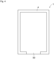
- the non-fixed portion 50 is preferably provided at the outer peripheral portion of the photovoltaic power generation sheet 1, that is, the lower edge portion on the lower side of four linear border portions (upper border portion, left and right border portions, and lower border portion). In this case, as illustrated in Fig.
- the non-fixed portion 50 may be provided in the central portion of the lower border portion of the photovoltaic power generation sheet 1, as illustrated in Fig. 5 , the non-fixed portions 50 may be provided in both side portions of the lower border portion of the photovoltaic power generation sheet 1, or as illustrated in Fig. 6 , a plurality of non-fixed portions 50 arranged at equal intervals may be provided in the lower border portion of the photovoltaic power generation sheet 1.
- the non-fixed portions 50 are provided at corner portions where two side edge portions (two side border portions) of the photovoltaic power generation sheet 1 meet the lower edge portion (lower border portion) of the photovoltaic power generation sheet 1, without the bonder 4 being provided. As a result, water that has entered between the photovoltaic power generation sheet 1 and the installation surface 3 can be discharged without being accumulated in these corner portions.
- the bonder 4 is not provided at the bottom position and the non-fixed portion 50 is provided.
- the bottom of the lower edge portion (lower border portion) of the photovoltaic power generation sheet 1 refers to the deepest portion (lowermost portion) in the downward direction of the installation surface 3.
- the shape of the photovoltaic power generation sheet 1 is rectangular in plan view, the entire lower edge portion (lower border portion) is the bottom.
- the shape of the photovoltaic power generation sheet 1 is a circular shape in plan view, the top portion of the lower edge portion of the semicircular arc shape is the bottom.
- At least one non-fixed portion 50 on the outer peripheral portion of the photovoltaic power generation sheet 1 may be provided at left and right side edge portions (left and right border portions) and/or upper edge portions (upper border portions on the upper side).
- a plurality of bonders 4 are provided at equal intervals on the left and right side edge portions (left and right border portions) and the upper edge portion (upper border portion on the upper side) of the photovoltaic power generation sheet 1, and a plurality of non-fixed portions 50 are provided at equal intervals.
- a plurality of bonders 4 are provided at equal intervals on the left and right side edge portions (left and right border portions) and the upper edge portion (upper border portion on the upper side) of the photovoltaic power generation sheet 1, and a plurality of non-fixed portions 50 are provided at equal intervals.
- the steam can be discharged from the non-fixed portions 50 at the left and right side edge portions and/or the upper edge portion of the photovoltaic power generation sheet 1.
- the non-fixed portion 50 of the outer peripheral portion of the photovoltaic power generation sheet 1 has such a size that the photovoltaic power generation sheet 1 does not greatly vibrate due to wind even when the wind enters between the photovoltaic power generation sheet 1 and the installation surface 3 from the opening of the non-fixed portion 50.
- the size of the opening in the non-fixed portion 50 is about 1 mm or more and 5 mm or less.
- the installation surface 3 Since the installation surface 3 is inclined, the water that has entered between the photovoltaic power generation sheet 1 and the installation surface 3 is discharged from the non-fixed portion 50 in the lower edge portion of the photovoltaic power generation sheet 1.
- a direction going up to a high position is an upper side
- a direction going down to a low position is a lower side
- a direction orthogonal to the up-and-down direction and along the installation surface 3 is a lateral direction.
- the angle formed by the installation surface 3 with respect to the horizontal plane is preferably 1.5° or more, more preferably 2° or more, and still more preferably 5° or more so that the water on the installation surface 3 can favorably flow down in the downward direction of the installation surface 3.
- a hook-and-loop fastener such as Magic Tape (registered trademark), a magnet, a double-sided tape, or the like may be used as the sealing member instead of the bonder 4.
- Figs. 8 and 9 illustrate an installation structure 20 for a photovoltaic power generation sheet according to a second embodiment of the present disclosure.
- the installation structure 20 according to the second embodiment also includes the installation surface 3, the photovoltaic power generation sheet 1, and the bonder 4 as a sealing member that closes a gap between the outer peripheral edge of the photovoltaic power generation sheet 1 and the installation surface 3.
- the bonder 4 is provided between the entire photovoltaic power generation sheet 1 and the installation surface 3. The entire photovoltaic power generation sheet 1 is bonded to the installation surface 3 by the bonder 4, whereby the photovoltaic power generation sheet 1 is fixed to the installation surface 3.
- the bonder 4 bonds the entire photovoltaic power generation sheet 1 to the installation surface 3, so that it is possible to prevent generation of a gap between the entire photovoltaic power generation sheet 1 and the installation surface 3.
- the vibration of the photovoltaic power generation sheet 1 due to the influence of the wind can be further suppressed.
- the vibration of the installation surface can be widely suppressed in the cured layer of the bonder 4, it is possible to effectively suppress the vibration of the photovoltaic power generation sheet 1 due to the influence of the vibration of the installation surface 3. Therefore, since the angle of the photovoltaic power generation sheet 1 with respect to sunlight can be more stably maintained, the power generation efficiency of the photovoltaic power generation sheet 1 can be more stably maintained.
- Figs. 10 and 11 illustrate an installation structure 21 for a photovoltaic power generation sheet according to a third embodiment of the present disclosure.
- the installation structure 21 according to the third embodiment further includes a cover member 15 having an ultraviolet ray blocking property in addition to the configuration of the installation structure 20 illustrated in the second embodiment.
- the cover member 15 includes a base portion 16 having a long and rectangular plate shape in plan view, and a cover portion 17 having a long plate shape rising from the base portion 16 along one long edge of the base portion 16.
- the cover member 15 has a shape in which the cover portion 17 is bent by 90° with respect to the base portion 16.
- the cover member 15 is installed on the installation surface 3 in such a manner that the base portion 16 is adjacent to the outside of the photovoltaic power generation sheet 1 in such a manner that the cover portion 17 is disposed along the outer peripheral edge of the photovoltaic power generation sheet 1.
- the cover member 15 covers the bonder 4 between the outer peripheral edge of the photovoltaic power generation sheet 1 and the installation surface 3.
- the cover member 15 blocks the ultraviolet ray, so that the bonder 4 can be prevented from being irradiated with ultraviolet rays.
- deterioration of the bonder 4 due to ultraviolet rays can be suppressed, so that a state in which the photovoltaic power generation sheet 1 and the installation surface 3 are bonded by the bonder 4 can be maintained for a long period of time.
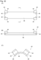
- the bonder 4 is not necessarily provided between the entire photovoltaic power generation sheet 1 and the installation surface 3. Similarly to the installation structure 2 of the first embodiment, the bonder 4 may be provided only between the outer peripheral portion of the photovoltaic power generation sheet 1 and the installation surface 3.
- Figs. 12 and 13 illustrate an installation structure 22 of the photovoltaic power generation sheet according to a fourth embodiment of the present disclosure.
- the cover member 15 has an ultraviolet ray blocking property, and includes the base portion 16 and the cover portion 17 described above, and a covered portion 18 having a long and rectangular plate shape in plan view.
- the covered portion 18 horizontally protrudes from the cover portion 18 at the upper end portion of the cover portion 18, and the cover member 15 has a shape in which the base portion 16 and the covered portion 18 are bent by 90° to the opposite side with respect to the cover portion 17.
- the base portion 16 is installed on the installation surface 3 adjacent to the outside of the photovoltaic power generation sheet 1 in such a manner that the cover portion 17 is disposed along the outer peripheral edge of the photovoltaic power generation sheet 1, and the covered portion 18 protrudes inward from the outer peripheral edge of the photovoltaic power generation sheet 1 to cover the front surface of the photovoltaic power generation sheet 1.
- the cover member 15 covers the bonder 4 between the outer peripheral edge of the photovoltaic power generation sheet 1 and the installation surface 3, and covers a portion having a predetermined width from the outer peripheral edge on the front surface of the photovoltaic power generation sheet 1.
- the cover member 15 is provided with the covered portion 18, even in a case where a gap (not illustrated) is generated between the cover member 15 and the outer peripheral edge of the photovoltaic power generation sheet 1 (even in a case where the cover portion 17 of the cover member 15 is not in close contact with the outer peripheral edge of the photovoltaic power generation sheet 1), it is possible to suppress irradiation of the bonder 4 with ultraviolet rays.
- the fixation of the photovoltaic power generation sheet 1 to the installation surface 3 can be reinforced, and the outer peripheral portion of the photovoltaic power generation sheet 1 can be prevented from fluttering due to wind or the like.
- the plan view shape of the covered portion 18 is not particularly limited as long as it can press the front surface of the photovoltaic power generation sheet 1, and various shapes can be formed.
- the covered portion 18 preferably has a size that presses a range other than the power generator 7 of the photovoltaic power generation sheet 1, for example, a range of the sealing edge member 10 on the outer peripheral portion.
- the lower limit of the contact pressure between the covered portion 18 and the photovoltaic power generation sheet 1 is preferably 0.5 MPa or more, more preferably 1 MPa or more, and more preferably 2.5 MPa or more, and the upper limit of the contact pressure between the covered portion 18 and the photovoltaic power generation sheet 1 is preferably 25 MPa or less, more preferably 15 MPa or less, and more preferably 10 MPa or less.
- This contact pressure can be measured using pressure-sensitive paper or the like.
- an edge 18c between the pressing surface 18a and the side surface 18b in contact with the front surface of the photovoltaic power generation sheet 1 is preferably processed into a C surface or an R surface as illustrated in Figs. 14 (A) and 14(B). Since the edge 18c of the covered portion 18 comes into contact with the front surface of the photovoltaic power generation sheet 1 when the photovoltaic power generation sheet 1 is deformed by wind or the like, it is possible to suppress damage to the photovoltaic power generation sheet 1 due to pressing of the covered portion 18. In particular, unlike a rigid solar cell, it is difficult to predict the deformation of the photovoltaic power generation sheet 1 that is easily elastically deformed due to wind or the like.
- the photovoltaic power generation sheet 1 for a longer period of time by effectively suppressing the stress concentration at the contact location with the edge 18c of the covered portion 18.
- a spacer or the like having elasticity may be provided between the photovoltaic power generation sheet 1 and the covered portion 18.
- the material of the elastic member is not particularly limited, and examples thereof include rubber, resin, and metal washers.
- the covered portion 18 of the cover member 15 is provided with an elongated convex portion 19 protruding from the lower surface.
- the convex portion 19 extends in the length direction of the covered portion 18.
- the convex portion 19 is provided on the covered portion 18 in contact with the front surface of the photovoltaic power generation sheet 1, so that the outer peripheral portion of the photovoltaic power generation sheet 1 is compressed by the convex portion 19.
- the convex portion 19 is provided in the covered portion 18 in such a manner that the convex portion 19 is in contact with a range other than the power generator 7 of the photovoltaic power generation sheet 1, for example, a range of the sealing edge member 10 of the outer peripheral portion.
- the lower limit of the crushing ratio of the photovoltaic power generation sheet 1 by the convex portion 19 is preferably 1% or more, more preferably 5% or more, and more preferably 10%
- the upper limit of the crushing ratio of the photovoltaic power generation sheet 1 by the convex portion 19 is preferably 25% or less, more preferably 20% or less, and more preferably 15% or less.
- the bonder 4 is not necessarily provided between the entire photovoltaic power generation sheet 1 and the installation surface 3. Similarly to the installation structure 2 of the first embodiment, the bonder 4 may be provided only between the outer peripheral portion of the photovoltaic power generation sheet 1 and the installation surface 3.
- the material of the cover member 15 illustrated in the third and fourth embodiments is not particularly limited as long as it has an ultraviolet ray blocking property.
- a frame made of metal such as aluminum, resin, composite reinforced material, or the like can be used.
- the cover member 15 can be fixed to the installation surface 3 at the base portion 16 using, for example, a bolt or a bonder.
- the entire circumference of the photovoltaic power generation sheet 1 is surrounded by the cover portion 17 of the cover member 15, so that it is possible to suppress deterioration of the bonder 4 over the entire circumference.
- a plurality of (four in the illustrated example) linear cover members 15 are prepared in Figs. 10 and 12 , and linear cover members 15 are installed for the respective border portions of the photovoltaic power generation sheet 1.
- one annular cover member may be prepared, and an annular cover member may be installed around the photovoltaic power generation sheet 1.
- the present disclosure does not exclude a case where the entire circumference of the photovoltaic power generation sheet 1 is not surrounded by the cover portion 17 of the cover member 15.
- the cover member 15 including the plate-shaped cover portion 17 may be provided only on a part of the periphery of the photovoltaic power generation sheet 1, or the cover member 15 may be provided on the entire circumference of the photovoltaic power generation sheet 1, and the cover portion 17 may have a rod shape arranged at a plurality of intervals instead of one plate shape. Even in this case, it is possible to suppress irradiation of the bonder 4 with ultraviolet rays at the location where the cover member 15 is provided, so that it is possible to suppress deterioration of the bonder 4.
- the cover member 15 may not include the base portion 16, and may be fixed to the installation surface 3 by extending the cover portion 17 downward and embedding the cover portion 17 in the installation surface 3.
- the cover portion 17 is provided with a protrusion or the like on the outer peripheral surface so that the cover portion 17 is easily embedded with respect to the installation surface 3 and the embedded cover portion 17 is hardly removed from the installation surface 3.
- a large contact area between the installation surface 3 and the cover portion 17 embedded in the installation surface 3 is secured by making the cover portion 17 hollow, and the embedded cover portion 17 is hardly removed from the installation surface 3.
- a protrusion or the like may be provided on the inner peripheral surface of the cover portion 17 to make it difficult for the embedded cover portion 17 to come off from the installation surface 3.
- the covered material covering the bonder 4 between the outer peripheral edge of the photovoltaic power generation sheet 1 and the installation surface 3 may be a joint material such as cement instead of the cover member 15 described above.
- the joint material may be applied around the photovoltaic power generation sheet 1 in such a manner of covering the bonder 4 between the outer peripheral edge of the photovoltaic power generation sheet 1 and the installation surface 3.
- the installation structure for the present disclosure is not limited to the installation structure for the above embodiment, and can be variously modified.
- the gap between the photovoltaic power generation sheet 1 and the installation surface 3 is filled with a single bonder 4.
- the bonder 4 may include a first bonder for bonding the installation surface 3 and the filler, and a second bonder for bonding the filler and the photovoltaic power generation sheet 1. Even in this case, the same effects as those of the installation structure for the above embodiment can be obtained.
- the viscosity of the filler is preferably 800cP or more.
- the photovoltaic power generation sheet 1 may be fixed to the installation surface 3 using a fixing member.
- the fixing member is not particularly limited, and examples thereof include a flange member having a flange portion such as a bolt or a rivet, a sandwiching member, and a staple.
- Examples of the sandwiching member include a clamp and a vise.
- the photovoltaic power generation sheet 1 can be fixed to the installation surface 3 with a higher fixing force without deteriorating the power generation performance of the photovoltaic power generation sheet 1 by the flange member or the sandwiching member disposed in the range other than the power generator 7 of the photovoltaic power generation sheet 1, for example, in the range of the sealing edge member 10 on the outer peripheral portion.
- the flange member or the sandwiching member may be fixed to the outer peripheral portion of the photovoltaic power generation sheet 1 on a part of the outer peripheral portion or over the entire circumference.
- the fixing member include hanging members such as a hook, a lock, and an L-shaped hook.
- hanging members such as a hook, a lock, and an L-shaped hook.
- the inside of the fixing hole and the peripheral edge portion of the fixing hole may be covered with metal, resin, or the like.
- the material of the flange member, the sandwiching member, and the hanging member described above is not particularly limited, and examples thereof include a metal, a resin, a composite reinforced material, and the like.
- the metal include aluminum, SUS, and a coated metal member.
- the resin include polypropylene, polyethylene, hard vinyl chloride, polycarbonate, polyamide, and PPS.
- the composite reinforced material include those containing the resin, carbon, glass, and metal fibers.
- the flange member, the sandwiching member, and the hanging member are fixed to the installation surface 3.
- the fixing method with respect to the installation surface 3 is not particularly limited, and examples thereof include bonding, sandwiching, bolt/nut, pinning, welding, welding, and screwing with respect to the installation surface 3.
- the bonder 4 suppresses vibration of the photovoltaic power generation sheet 1 due to the influence of wind, and suppresses vibration caused by vibration of the installation surface 3.
- the cover member 15 described above may be used as a sealing member, and the cover member 15 may be installed around the photovoltaic power generation sheet 1 instead of the bonder 4.
- the sealing member of the present disclosure may use a joint material, and a gap between at least the outer peripheral portion of the photovoltaic power generation sheet 1 and the installation surface 3 may be filled with the joint material instead of the bonder 4.
- a high-viscosity resin, cement, or the like can be used as the joint material.
- the lower limit of the viscosity of the joint material is preferably 0.1 Pa ⁇ s or more, more preferably 10 Pa ⁇ s or more, and the upper limit of the viscosity of the joint material is preferably 10,000 Pa ⁇ s or less, more preferably 1000 Pa ⁇ s or less.
- the shape of the joint material can be maintained not only in the horizontal direction but also in the vertical direction, so that the gap between the photovoltaic power generation sheet 1 and the installation surface 3 can be effectively filled.
- the joint material when the joint material is applied to the installation surface 3 or the photovoltaic power generation sheet 1, the joint material can be easily expanded, so that construction can be improved.
- the joint material may be provided only between the outer peripheral portion of the photovoltaic power generation sheet 1 and the installation surface 3.
- the lower limit is preferably 5 mm or more, more preferably 100 mm or more, more preferably 150 mm or more, and the upper limit is 250 mm or less, more preferably 200 mm or less, more preferably 175 mm or less as the length in the direction from the outer peripheral edge of the photovoltaic power generation sheet 1 toward the inside along the installation surface 3.
- the vibration of the photovoltaic power generation sheet 1 due to the influence of wind can be effectively suppressed, and at the same time, the weight load on the installation surface 3 can be reduced, and the photovoltaic power generation sheet 1 can also be installed on the installation surface 3 such as a fragile roof.
- a cavity closed to the outside is generated between the photovoltaic power generation sheet 1 and the installation surface 3.
- stress is generated in the photovoltaic power generation sheet 1 in a direction perpendicular to the installation surface 3, and the photovoltaic power generation sheet 1 may be broken.
- it is preferable to use a porous material as the joint material, or it is preferable to form an air hole in the joint material.
- the photovoltaic power generation sheet 1 can be stably installed for a longer period of time.
- the lower limit of the size of the air hole is preferably 20mm 2 or more, more preferably 25mm 2 or more, more preferably 50mm 2 or more, and the upper limit is preferably 200mm 2 or less, more preferably 150mm 2 or less, more preferably 100mm 2 or less as the total area.
- the air hole is preferably provided with a gradient so that rainwater is less likely to enter from the outside to the inside of the joint material.
- a lid member made of a hard resin, metal, or ceramic may be used as the sealing member of the present disclosure, and the gap between the outer peripheral edge of the photovoltaic power generation sheet 1 and the installation surface 3 may be closed by the lid member to suppress the air from entering between the photovoltaic power generation sheet 1 and the installation surface 3. As a result, it is possible to suppress the vibration of the photovoltaic power generation sheet 1 due to the influence of the wind.
- the photovoltaic power generation sheet 1 may be fixed to the installation surface 3 by the bonder 4.
- the photovoltaic power generation sheet 1 is fixed to the installation surface 3 by the bonder 4, as long as the bonder 4 can bond the photovoltaic power generation sheet 1 to the installation surface 3, it is not necessary to bond the entire photovoltaic power generation sheet 1 or the entire circumference of the outer peripheral portion of the photovoltaic power generation sheet 1 to the installation surface 3.
- the photovoltaic power generation sheet 1 may be fixed to the installation surface 3 using the fixing member described above instead of the bonder 4, and it is preferable to fix the photovoltaic power generation sheet 1 using the bonder 4 from the viewpoint of suppressing breakage of the photovoltaic power generation sheet 1.
- the bonder 4 and the above-mentioned fixing member are not necessarily required as long as the photovoltaic power generation sheet 1 can be fixed to the installation surface 3 by the joint material.
- the photovoltaic power generation sheet 1 is fixed to the installation surface 3 by the bonder 4 without using the bonder 4 as a sealing member, it is preferable that there is no possibility that the power generator 7 of the photovoltaic power generation sheet 1 is bent and broken when the photovoltaic power generation sheet 1 needs to be peeled off and recovered from the installation surface 3.
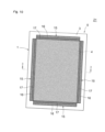
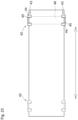
- the bonder 4 extends in one direction (lateral direction in Fig. 16 ) of the photovoltaic power generation sheet 1 and is disposed at intervals in another direction (longitudinal direction in Fig. 16 ) orthogonal to the one direction.
- the bonder 4 extends in the shortitudinal direction of the photovoltaic power generation sheet 1 having a rectangular shape in plan view, and is disposed at intervals in the longitudinal direction.
- the bonder 4 is provided in a portion avoiding the power generator 7 in the photovoltaic power generation sheet 1 (a portion not overlapping the power generator 7 in plan view).
- the bonder 4 is provided at a boundary portion between adjacent power generators 7.
- the bonder 4 is provided at all the boundary portions. That is, it is preferable that the bonders 4 are provided at intervals in the longitudinal direction of the photovoltaic power generation sheet 1 in such a manner of sandwiching the respective power generators 7 from both sides.
- the fixation of the photovoltaic power generation sheet 1 and the installation surface 3 by the bonder 4 positioned next in the longitudinal direction is released.
- a portion (the power generator 7 and the like) adjacent to the released bonder 4 can be peeled off from the installation surface 3 without any difficulty.
- the portion peeled off from the installation surface 3 is folded over the remaining portion.
- a hook-and-loop fastener such as Magic Tape (registered trademark), a magnet, a double-sided tape, or the like may be used in addition to the bonder 4.
- the sealing member of the present disclosure may use a material constituting the installation surface 3 as illustrated in Fig. 18 .
- the photovoltaic power generation sheet 1 is installed on the installation surface 3 by embedding the outer peripheral portion under the installation surface 3.
- a range other than the power generator 7 of the photovoltaic power generation sheet 1 for example, a range of the sealing edge member 10 of the outer peripheral portion under the installation surface 3. Since the outer peripheral portion of the photovoltaic power generation sheet 1 is embedded under the installation surface 3, the photovoltaic power generation sheet 1 is fixed to the installation surface 3, and the gap between the outer peripheral edge of the photovoltaic power generation sheet 1 and the installation surface 3 is closed by the material forming the installation surface 3.
- the photovoltaic power generation sheet 1 and the installation surface 3 are fixed using a bonder or the fixture described above.
- a portion exposed on the installation surface 3 may be fixed to the installation surface 3 with a bonder, or a portion embedded under the installation surface 3 may be fixed to the ground or the like under the installation surface 3 using the fixture described above.
- the upper layer and the lower layer sandwiching the outer peripheral portion of the photovoltaic power generation sheet 1 embedded under the installation surface 3 may have the same or different geologies.
- the photovoltaic power generation sheet 1 may be placed on a layer on which soil, sand, gravel, or the like is deposited, and a layer in which concrete or the like is solidified may be provided on the outer peripheral portion of the photovoltaic power generation sheet 1, so that the outer peripheral portion of the photovoltaic power generation sheet 1 may be embedded under the installation surface 3.
- the outer peripheral portion of the photovoltaic power generation sheet 1 is bent downward and embedded under the installation surface 3.
- the outer peripheral portion of the photovoltaic power generation sheet 1 can be embedded under the installation surface 3 without being bent downward, in this case, soil, sand, gravel, and the like are highly accumulated on the outer peripheral portion of the photovoltaic power generation sheet 1.
- soil, sand, gravel, and the like are highly accumulated on the outer peripheral portion of the photovoltaic power generation sheet 1.
- there is a possibility that sunlight incident on the power generator 7 of the photovoltaic power generation sheet 1 is blocked by highly deposited soil, sand, gravel, or the like, and there is a possibility that the power generation amount of the photovoltaic power generation sheet 1 decreases.
- an electric box 40 for outputting electricity generated by the power generator 7 of the photovoltaic power generation sheet 1 to an external device such as a power conditioner is preferably disposed in a portion of the outer peripheral portion of the photovoltaic power generation sheet 1 and embedded under the installation surface 3.
- the electric box 40 can be prevented from being exposed to wind and rain or sunlight, so that the durability of the electric box 40 can be improved.
- the electric box 40 may be disposed on another portion of the outer peripheral portion of the photovoltaic power generation sheet 1 and exposed on the installation surface 3. When the electric box 40 is exposed on the installation surface 3, maintainability can be improved when the electric box 40 is broken or when connection failure occurs.
- the outer peripheral portion of the photovoltaic power generation sheet 1 is embedded under the installation surface 3 over the entire circumference. However, only a portion of the outer peripheral portion of the photovoltaic power generation sheet 1 may be embedded under the installation surface 3, and the remaining portion may be exposed on the installation surface 3. In this case, the gap between the outer peripheral edge of the photovoltaic power generation sheet 1 and the installation surface 3 can be closed using the other sealing member described above.
- the installation surface 3 may be a corrugated surface in which a plurality of crest portions and a plurality of valley portions are bent in such a manner of being alternately arranged in addition to a flat horizontal plane without inclination.
- the maximum flexural radius of the photovoltaic power generation sheet 1 is preferably 50 mm or more, more preferably 75 mm or more, and more preferably 100 mm or more.
- the photovoltaic power generation sheet 1 When the maximum flexural radius of the photovoltaic power generation sheet 1 is in the above range, the photovoltaic power generation sheet 1 can be deformed while being prevented from being broken according to the shape of the installation surface 3 having a wave shape, and the photovoltaic power generation sheet 1 can be installed on the installation surfaces 3 having various shapes.
- the lower limit of the flexural radius of the power generator 7 of the photovoltaic power generation sheet 1 is preferably 50 mm or more, more preferably 75 mm or more, and more preferably 100 mm or more, and the upper limit of the flexural radius of the power generator 7 is preferably 300 mm or less, more preferably 200 mm or less, and more preferably 150 mm or less.
- the power generator 7 of the photovoltaic power generation sheet 1 can be improved in followability to various shapes of the installation surface 3 while suppressing breakage, and an effective light receiving surface area can be increased.
- the installation surface 3 may have a corner portion 30 as illustrated in Figs. 20 and 21 .
- the photovoltaic power generation sheet 1 When the photovoltaic power generation sheet 1 is installed on the installation surface 3 across the corner portion 30, the photovoltaic power generation sheet 1 may be damaged at the corner portion 30. Therefore, even when the photovoltaic power generation sheet 1 is installed on the installation surface 3 across the corner portion 30, it is necessary to make damage unlikely to occur.
- the corner portion 30 refers to a protruding corner portion that is adjacent to at least one installation surface 3 and protrudes in a convex shape. Examples of the corner portion 30 include a ridge of a roof, an upper corner of a sparkle, and an upper corner of an eaves edge.
- the ridge includes a large ridge, a getting-off ridge (corner ridge), and a juvenile ridge.
- the ridge also includes an upper end portion of a side roof.
- the roof of this type is not particularly limited, and examples thereof include a gable roof, a hip roof, a side roof, a square roof, a purlin roof, a sloped roof, a passable roof, a sawtooth roof, and a peg roof.
- the building having a roof may be a non-residential building or a residential building. Examples of the non-residential building include a store, a warehouse, a factory, a meeting place, a gymnasium, a parking lot, and the like.
- the installation surface 3 having the corner portion 30 is not limited to the roof, and examples thereof include a wall surface, a floor surface, and the like having a stepped convex portion and/or a local convex portion.
- the wall surface include wall surfaces formed of concrete, metal siding, a wooden wall plate, a soil wall, and the like.
- An installation structure 25 illustrated in Figs. 20 and 21 includes an installation surface 3, a photovoltaic power generation sheet 1, and a spacer member 42. Since the photovoltaic power generation sheet 1 is installed on the installation surface 3 in a state of being attached to the spacer member 42, it is possible to suppress the corner portion 30 of the installation surface 3 from strongly hitting the photovoltaic power generation sheet 1.
- the spacer member 42 preferably keeps the corner portion 30 of the installation surface 3 and the photovoltaic power generation sheet 1 in a non-contact state.
- the spacer member 42 includes a spacer 46 and at least one attachment portion 43 (a pair in Figs. 20 and 21 ).
- one of the pair of attachment portions 43 is attached to one end portion of the photovoltaic power generation sheet 1 in the width direction, and the other of the pair of attachment portions 43 is attached to the other end portion of the photovoltaic power generation sheet 1 in the width direction.
- the spacer 46 is disposed between the photovoltaic power generation sheet 1 and the corner portion 30 of the installation surface 3 by the attachment portion 43. As a result, even when the photovoltaic power generation sheet 1 is installed across the corner portion 30 with respect to the installation surface 3 having the corner portion 30, it is possible to suppress the photovoltaic power generation sheet 1 from being damaged by the corner portion 30.
- the spacer member 42 may be attached to the photovoltaic power generation sheet 1 in a retrofitting manner at a construction site or may be attached at the time of factory shipment.
- the lower limit of the thickness of the spacer 46 is preferably 1 mm or more, more preferably 3 mm or more, and more preferably 5 mm or more, and the upper limit of the thickness of the spacer 46 is preferably 20 mm or less, more preferably 15 mm or less, and more preferably 10 mm or less.
- the thickness of the spacer 46 is in the above range, it is possible to suppress damage at a contact portion between the corner portion 30 of the installation surface 3 and the photovoltaic power generation sheet 1.
- the spacer 46 preferably keeps the corner portion 30 of the installation surface 3 and the photovoltaic power generation sheet 1 in a non-contact state.
- the spacer 46 is formed to extend from one end portion to the other end portion of the photovoltaic power generation sheet 1 in the direction in which the corner portion 30 extends. That is, the spacer 46 extends over the entire length in the width direction of the photovoltaic power generation sheet 1.
- the spacer 46 may be longer than the width of the photovoltaic power generation sheet 1 as long as the spacer 46 extends over the entire length in the width direction of the photovoltaic power generation sheet 1.
- Examples of the material of the spacer 46 include synthetic resin, metal, carbon, pulp, natural rubber, and ceramic. From the viewpoint of being used outdoors, examples of the material of the spacer 46 include polypropylene, polyethylene, ABS resin, polyvinyl chloride, methacrylic resin, phenol resin, epoxy resin, polyurethane resin, melamine resin, unsaturated polyester resin, PPS, NBR, SBR and the like as long as the material of the spacer 46 is a synthetic resin.
- Examples of the metal include an aluminum alloy, a stainless alloy, steel, niobium, a nickel alloy, zirconium, chromium, and a titanium alloy.
- the spacer 46 may be formed of one material among the above-described materials, or may be formed of a plurality of materials. Further, the spacer 46 may be formed of one layer or a plurality of layers.
- the edges 48 on both sides of the upper surface of the spacer 46 are preferably chamfered. Since the edge 48 of the spacer 46 comes into contact with the back surface of the photovoltaic power generation sheet 1 when the spacer 46 supports the photovoltaic power generation sheet 1, the damage to the photovoltaic power generation sheet 1 can be further suppressed by performing chamfering.
- the chamfering may be C-face machining or R-face machining.
- the attachment portion 43 includes a plurality of upper facing portions 44 and a plurality of joint portions 45.
- one of the pair of attachment portions 43 is attached to one end portion of the photovoltaic power generation sheet 1 in the width direction, and the other of the pair of attachment portions 43 is attached to the other end portion of the photovoltaic power generation sheet 1 in the width direction.
- the upper facing portion 44 faces a front surface including the light receiving surface of the photovoltaic power generation sheet 1.
- the upper facing portion 44 faces an upper side portion of the sealing edge member 10. As illustrated in Fig. 22(C) , the upper facing portion 44 is disposed on the upper side with a space from the spacer 46, and a part of the photovoltaic power generation sheet 1 is disposed between the upper facing portion 44 and the spacer 46.
- the material of the upper facing portion 44 may be the same as or different from the material of the spacer 46. Since the upper facing portion 44 is directly exposed to wind and rain, it is preferable that the upper facing portion has higher weather resistance than the spacer 46.
- a synthetic resin, a composite material, a metal, carbon, ceramic, or the like is preferably used.
- a composite reinforced material or metal is more preferable.
- the material of the reinforced fibers contained in a composite reinforced material is not particularly limited, and examples thereof include glass fibers, carbon fibers, aramid fibers, and metal fibers.
- the lower limit of the content of the fiber is preferably 5% by mass or more, more preferably 15% by mass or more, and still more preferably 30% by mass or more with respect to the total mass of the upper facing portion 44.
- the strength of the upper facing portion 44 can be set to an appropriate strength.
- the upper limit of the content of the fibers is preferably 80 mass% or less, more preferably 70 mass% or less, and still more preferably 60 mass% or less with respect to the total mass of the upper facing portion 44.
- the color is preferably close to black. By preventing light transmission, deterioration of the synthetic resin contained in the composite reinforced material can be reduced.
- the joint portion 45 faces the end surface of the photovoltaic power generation sheet 1 and connects the upper facing portion 44 and the spacer 46.
- the upper end portion of the joint portion 45 is connected to the lower surface of the upper facing portion 44, and the lower end portion of the joint portion 45 is connected to the upper surface of the spacer 46.
- a plurality of joint portions 45 are connected to the plurality of upper facing portions 44 on a one-to-one basis.
- the material of the joint portion 45 may be the same as or different from the material of the spacer 46 and/or the upper facing portion 44.
- the spacer 46, the upper facing portion 44, and the joint portion 45 can be integrally formed of the same material, so that damage on not only the back surface but also the side surface of the photovoltaic power generation sheet 1 can be reduced.
- a plurality of upper facing portions 44 of the attachment portion 43 is slidable on the front surface of the photovoltaic power generation sheet 1 in a direction intersecting the direction in which the corner portion 30 of the installation surface 3 extends.
- the spacer 46 is movable in the direction intersecting the direction in which the corner portion 30 of the installation surface 3 extends with respect to the photovoltaic power generation sheet 1 by the attachment portion 43.
- the spacer member 42 moves with respect to the photovoltaic power generation sheet 1, and the photovoltaic power generation sheet 1 may move with respect to the spacer member 42, and the photovoltaic power generation sheet 1 and the spacer member 42 may move relative to each other.
- the method of moving the attachment portion 43 is not particularly limited, and for example, a rail portion may be provided in the photovoltaic power generation sheet 1, and the attachment portion 43 may be attached to the rail portion.
- the rail include a guide bar, a groove, and a wire.
- the spacer 46 is attached to the photovoltaic power generation sheet 1 by the attachment portion 43. Then, as illustrated in Figs. 20 and 21 , the photovoltaic power generation sheet 1 is placed on the installation surface 3 across the corner portion 30 while covering the corner portion 30 of the installation surface 3 with the spacer 46. Under this state, the gap between the outer peripheral edge of the photovoltaic power generation sheet 1 and the installation surface 3 is closed using the sealing member such as the bonder, the cover member, and the joint material described above with respect to the installation surface 3.
- the sealing member may not block the gap between the outer peripheral edge of the photovoltaic power generation sheet 1 and the installation surface 3 in the vicinity of the spacer 46 (in the vicinity of the corner portion 30). That is, the sealing member closes the gap between the outer peripheral edge of the photovoltaic power generation sheet 1 and the installation surface 3 at the 30 other than the corner portion of the installation surface 3.
- the photovoltaic power generation sheet 1 and the installation surface 3 need to be fixed, the photovoltaic power generation sheet 1 and the installation surface 3 are fixed using the bonder or the fixture described above. According to the installation structure 25 illustrated in Figs. 20 and 21 , since the spacer 46 is disposed between the corner portion 30 of the installation surface 3 and the photovoltaic power generation sheet 1, damage to the photovoltaic power generation sheet 1 due to the corner portion 30 can be suppressed.
- the power generator 7 of the photovoltaic power generation sheet 1 may be positioned, or a portion between adjacent power generators 7 may be positioned. That is, the attachment portion 43 may be positioned at a position corresponding to power generator 7, or may be positioned between adjacent power generators 7.
- the spacer member 42 even when the power generator is positioned at a position overlapping the corner portion 30 in plan view, it is possible to prevent the photovoltaic power generation sheet 1 from being excessively bent.
- one spacer 46 is joint to the pair of attachment portions 43, but the spacer 46 may be joint to each of the pair of attachment portions 43, and the pair of spacers 46 may be disposed between the corner portion 30 of the installation surface 3 and the photovoltaic power generation sheet 1 to suppress the damage to the photovoltaic power generation sheet 1 due to the corner portion 30.
- the spacer member 42 can be easily attached to the photovoltaic power generation sheet 1 while obtaining the same effect, and the cost of the spacer member 42 can be reduced.
- the thickness of the spacer 46 is preferably set in consideration of the deflection amount of the photovoltaic power generation sheet 1.
- the pair of spacers 46 may keep the photovoltaic power generation sheet 1 and the corner portion 30 of the installation surface 3 in a non-contact state, or may bring the photovoltaic power generation sheet 1 partially into contact with the corner portion 30 of the installation surface 3.
- one spacer 46 is joint to the pair of attachment portions 43, and one spacer 46 may be joint to one attachment portion 43.
- the spacer 46 may be freely deformable by being formed of an elastically deformable material. As a result, the spacer 46 can be appropriately deformed according to the shape and size of the corner portion 30 of the installation surface 3.
- the flexural modulus of the spacer 46 is preferably larger than the flexural modulus of the photovoltaic power generation sheet 1. Since the spacer 46 receives an external force from the photovoltaic power generation sheet 1 when supporting the photovoltaic power generation sheet 1, when the flexural modulus is small, the spacer 46 can be deformed to a curvature radius close to the curvature radius of the corner portion 30.
- the flexural strength of the spacer 46 is not particularly limited, and is preferably 1.05 times or more and 5 times or less, more preferably 1.25 times or more and 3 times or less, and more preferably 1.5 times or more and 2 times or less the flexural strength of the photovoltaic power generation sheet 1.
- the flexural strength of the spacer 3 is preferably 15 MPa or more and 250 MPa or less, more preferably 25 MPa or more and 230 MPa or less, and more preferably 50 MPa or more and 210 MPa or less. In this way, it is possible to suppress deformation of the spacer 46 while reducing damage to the spacer 46 with respect to the photovoltaic power generation sheet 1.
- the photovoltaic power generation sheet 1 may have a photoelectric conversion layer containing amorphous silicon, or may have a photoelectric conversion layer having a tandem laminated structure containing amorphous silicon and a perovskite compound in a composite manner.
- the perovskite compound is contained in the photoelectric conversion layer, the dependence of the power generation efficiency of the perovskite compound is relatively low with respect to the incident angle of light, so that higher power generation efficiency can be obtained.
- the photovoltaic power generation sheet having the photoelectric conversion layer containing the perovskite compound has been described as one aspect of the photovoltaic power generation sheet 1, but in the installation structure for the present disclosure, the photovoltaic power generation sheet 1 can exhibit the same effect as long as the photovoltaic power generation sheet 1 is flexible.
- the photovoltaic power generation sheet of the present disclosure may be not only a sheet that can obtain a power generation effect by light, but also a sheet that converts light energy into another energy, for example, a light heating sheet (photovoltaic power-driven thermoelectric conversion device) that converts light energy into thermal energy.
- the present disclosure includes the installation structure for the photovoltaic power generation sheet according to the following items A to F in order to solve the problem that when the entire photovoltaic power generation sheet is fixed to the installation surface with a bonder or the like, or the outer peripheral portion of the photovoltaic power generation sheet is fixed to the installation surface with a bonder or the like over the entire circumference, the power generator may be bent when the photovoltaic power generation sheet 1 is peeled off from the installation surface, and stress is concentrated on the power generator to break the power generator in a case where the photovoltaic power generation sheet needs to be collected.
- An installation structure for a photovoltaic power generation sheet including:
- Item B The installation structure according to item A, wherein
- Item D The installation structure according to any one of items A to C, wherein the fixing member is at least one selected from a group consisting of a hook and loop fastener, a magnet, a double-sided tape, and a bonder.
- the fixing member is at least one selected from a group consisting of a hook and loop fastener, a magnet, a double-sided tape, and a bonder.
- Item E The installation structure according to any one of items A to D, wherein the photovoltaic power generation sheet has a flexural strength of 50 MPa or more and 200 MPa or less.
- Item F The installation structure according to any one of items A to E, wherein the power generator contains a perovskite compound.
- the photovoltaic power generation sheet being flexible can be easily installed on the installation surface such as the surface of the roof, and the photovoltaic power generation sheet can be easily peeled off from the installation surface while the breakage of the power generator is suppressed.
- the present disclosure includes, as a subject, the installation structure for the photovoltaic power generation sheet according to items G to M below in order to solve the problem that when the entire photovoltaic power generation sheet is fixed to the installation surface with a bonder or the like, or the outer peripheral portion of the photovoltaic power generation sheet is fixed to the installation surface over the entire circumference with a bonder or the like, water remains between the photovoltaic power generation sheet and the installation surface when water such as rainwater enters between the photovoltaic power generation sheet and the installation surface, but since the base member of the photovoltaic power generation sheet is formed of a resin material, when water remains between the photovoltaic power generation sheet and the installation surface, steam generated by vaporization of water may pass through the base member or water may penetrate the base member, and water may come into contact with the power generator, leading to deterioration of the photovoltaic power generation sheet.
- An installation structure for a photovoltaic power generation sheet including:
- Item H The installation structure according to item G, wherein the outer peripheral portion includes the non-fixed portion at a position of a bottom of the lower edge portion.
- Item I The installation structure according to item G or item H, wherein the outer peripheral portion includes the non-fixed portion at a position of a corner where each of left and right side edge portions of the outer peripheral portion meets the lower edge portion.
- Item J The installation structure according to any one of items G to I, wherein the outer peripheral portion includes at least one of the non-fixed portions at an upper edge portion of the outer peripheral portion.
- Item K The installation structure according to any one of items G to J, wherein the fixing member is at least one selected from a group consisting of a hook and loop fastener, a magnet, a double-sided tape, a bonder, a bolt, a screw, and a staple.
- the fixing member is at least one selected from a group consisting of a hook and loop fastener, a magnet, a double-sided tape, a bonder, a bolt, a screw, and a staple.
- Item L The installation structure according to any one of items G to K, wherein the photovoltaic power generation sheet includes a plurality of power generators containing a perovskite compound.
- Item M The installation structure according to any one of items G to L, wherein the photovoltaic power generation sheet has a flexural strength of 50 MPa or more and 200 MPa or less.
- the photovoltaic power generation sheet being flexible can be easily installed on the installation surface, and deterioration of the installed photovoltaic power generation sheet due to water such as rainwater can be suppressed.
- the present disclosure includes, as a subject, the installation structure for the photovoltaic power generation sheet according to the following items N to R in order to solve the problem that there is a possibility that the photovoltaic power generation sheet comes into contact with the top of the corner portion and the photovoltaic power generation sheet is damaged when the photovoltaic power generation sheet is installed across the corner portion such as the ridge of the roof.
- An installation structure for a photovoltaic power generation sheet including:
- Item O The installation structure according to item N, wherein the spacer extends from one end portion to the other end portion of a main body of the photovoltaic power generation sheet in the first direction.
- Item P The installation structure according to item N or O, wherein the spacer is attached to the photovoltaic power generation sheet in such a manner that the spacer is movable in a direction intersecting the first direction by the attachment portion.
- Item R The installation structure according to any one of items N to Q, wherein the spacer is formed in a curved shape in such a manner of covering the corner portion in a cross section orthogonal to the first direction.
- the installation structure there is an advantage that, in a case where the photovoltaic power generation sheet is installed across the corner portion on the installation surface having the corner portion, the photovoltaic power generation sheet is less likely to be damaged by the corner portion.
- the present disclosure includes a spacer member according to the following item S as a subject.
Landscapes
- Engineering & Computer Science (AREA)
- Architecture (AREA)
- Civil Engineering (AREA)
- Structural Engineering (AREA)
- Photovoltaic Devices (AREA)
Abstract
Description
- The present disclosure relates to an installation structure for a photovoltaic power generation sheet in which a photovoltaic power generation sheet is installed above an installation surface.
- Conventionally, a rigid solar cell using silicon for a power generation cell has been used (PTL 1). When this type of solar cell is installed, an installation angle of a solar cell with respect to sunlight is determined by installing an attachment base on an installation surface such as a roof and attaching the solar cell on the attachment base using rivets or the like.
- In recent years, flexible solar cells such as perovskite photovoltaic power generation sheets have become widespread. A photovoltaic power generation sheet of this type can adjust an installation angle with respect to sunlight by its own flexibility and is lightweight at the same time, and thus it is expected that the photovoltaic power generation sheet is directly installed on an installation surface without using an attachment base.
- PTL 1:
JPH 07-18797A - As illustrated in
Figs. 24 and25 , in a case where a photovoltaicpower generation sheet 100 is fixed to aninstallation surface 102 using arivet 101, when there is unevenness on theinstallation surface 102, agap 103 is generated between the photovoltaicpower generation sheet 100 and theinstallation surface 102. When wind enters between the photovoltaicpower generation sheet 100 and theinstallation surface 102 from thegap 103, the photovoltaicpower generation sheet 100 vibrates and the incident angle of sunlight on the photovoltaicpower generation sheet 100 becomes unstable, and therefore the power generation efficiency of the photovoltaic power generation sheet is reduced. - When the conventional rigid solar cell is increased in size by increasing the area or the like, the efficiency of construction work and the efficiency of the transportation industry decrease due to a significant increase in weight. On the other hand, since the photovoltaic power generation sheet is lightweight and does not cause a problem of a case where a rigid solar cell is increased in size, an increase in size has been studied. However, in a case where the size of the photovoltaic power generation sheet is increased, the above-described vibration due to the influence of wind becomes large, and the problem of the decrease in power generation efficiency due to the vibration becomes remarkable. This problem is unique to the photovoltaic power generation sheet.
- The present disclosure has been made in view of the above matters, and an object of the present disclosure is to provide an installation structure for a photovoltaic power generation sheet that can suppresses vibration of the photovoltaic power generation sheet due to wind in a state where the photovoltaic power generation sheet is installed above an installation surface.
- In order to achieve the above object, the present disclosure includes, as a subject, an installation structure for a photovoltaic power generation sheet according to the
following item 1. -
Item 1. An installation structure for a photovoltaic power generation sheet, including: - an installation surface;
- a photovoltaic power generation sheet installed above the installation surface; and
- a sealing member that closes a gap between an outer peripheral edge of the photovoltaic power generation sheet and the installation surface.
- The present disclosure includes the installation structure for the photovoltaic power generation sheet according to the following
item 2 as a preferable aspect of the installation structure for the photovoltaic power generation sheet according to theabove item 1. -
Item 2. The installation structure toitem 1, wherein the sealing member is formed of a bonder provided between at least an outer peripheral portion of the photovoltaic power generation sheet and the installation surface to bond the outer peripheral portion to the installation surface. - The present disclosure includes the installation structure for the photovoltaic power generation sheet according to the following
item 3 as a preferable aspect of the installation structure for the photovoltaic power generation sheet according to theabove item 2. -
Item 3. The installation structure according toitem 2, wherein the bonder has a loss factor of 0.01 or more and 0.3 or less. - The present disclosure includes the installation structure for the photovoltaic power generation sheet according to the following
item 4 as a preferable aspect of the installation structure for the photovoltaic power generation sheet according to theabove item 3. -
Item 4. The installation structure for the installation structure for a photovoltaic power generation sheet according toitem 3, wherein the bonder has a thickness of 3 mm or more and 20 mm or less. - The present disclosure includes the installation structure for the photovoltaic power generation sheet according to the following
item 5 as a preferable aspect of the installation structure for the photovoltaic power generation sheet according to theabove items 2 to 4. -
Item 5. The installation structure according to any one ofitems 2 to 4, wherein the bonder has a modulus of transverse elasticity of 0.1 MPa or more and 100 MPa or less. - The present disclosure includes the installation structure for the photovoltaic power generation sheet according to the following item 6 as a preferable aspect of the installation structure for the photovoltaic power generation sheet according to the
above items 2 to 5. - Item 6. The installation structure according to any one of
items 2 to 5, wherein the bonder has a viscosity of 800cP or more. - The present disclosure includes the installation structure for the photovoltaic power generation sheet according to the following
item 7 as a preferable aspect of the installation structure for the photovoltaic power generation sheet according to theabove items 2 to 6. -
Item 7. The installation structure according to any one ofitems 2 to 6, wherein the bonder includes at least one or more resin compositions selected from a vinyl acetate resin, an ethylene vinyl acetate resin, an epoxy resin, a cyanoacrylate resin, an acrylic resin, a chloroprene rubber, styrene, a butadiene rubber, a polyurethane resin, a silicone resin, and a modified silicone resin. - The present disclosure includes the installation structure for the photovoltaic power generation sheet according to the following
item 8 as a preferable aspect of the installation structure for the photovoltaic power generation sheet according to theabove items 2 to 7. -
Item 8. The installation structure according to any one ofitems 2 to 7, wherein the bonder is provided between the entire photovoltaic power generation sheet and the installation surface. - The present disclosure includes the installation structure for the photovoltaic power generation sheet according to the following
item 9 as a preferable aspect of the installation structure for the photovoltaic power generation sheet according to theabove items 2 to 8. -
Item 9. The installation structure according to any one ofitems 2 to 8, further including: - a cover member that covers the bonder between an outer peripheral edge of the photovoltaic power generation sheet and the installation surface, wherein
- the cover member has an ultraviolet ray blocking property.
- The present disclosure includes the installation structure for the photovoltaic power generation sheet according to the following
item 10 as a preferable aspect of the installation structure for the photovoltaic power generation sheet according to theabove item 9. -
Item 10. The installation structure according toitem 9, wherein the cover member includes a covered portion that covers a portion having a predetermined width from an outer peripheral edge on a front surface of the photovoltaic power generation sheet. - The present disclosure includes the installation structure for the photovoltaic power generation sheet according to the following
item 11 as a preferable aspect of the installation structure for the photovoltaic power generation sheet according to theabove item 1. -
Item 11. The installation structure according toitem 1, wherein the sealing member includes a cover member that covers a gap between an outer peripheral edge of the photovoltaic power generation sheet and the installation surface. - The present disclosure includes the installation structure for the photovoltaic power generation sheet according to the following
item 12 as a preferable aspect of the installation structure for the photovoltaic power generation sheet according to theabove item 1. -
Item 12. The installation structure according toitem 1, wherein the sealing member is formed of a joint material filled in a gap between at least an outer peripheral portion of the photovoltaic power generation sheet and the installation surface. - The present disclosure includes the installation structure for the photovoltaic power generation sheet according to the following
item 13 as a preferable aspect of the installation structure for the photovoltaic power generation sheet according to theabove items 1 to 12. -
Item 13. The installation structure according to any one ofitems 1 to 12, wherein the photovoltaic power generation sheet is flexible. - According to the installation structure for the photovoltaic power generation sheet of the present disclosure, it is possible to suppress vibration of the photovoltaic power generation sheet due to wind in a state where the photovoltaic power generation sheet is installed above the installation surface.
-
-
Fig. 1 is a schematic plan view illustrating an installation structure for a photovoltaic power generation sheet according to a first embodiment of the present disclosure. -
Fig. 2 is a cross-sectional view taken along line A-A ofFig. 1 . -
Fig. 3(A) is a cross-sectional view of the photovoltaic power generation sheet.Fig. 3(B) is an enlarged view of a part a inFig. 3(A). Fig. 3(C) is a cross-sectional view illustrating a state in which the power generator is cut along line B-B ofFig. 3(A) . -
Fig. 4 is a back view illustrating a modification of the photovoltaic power generation sheet. -
Fig. 5 is a back view illustrating a modification of the photovoltaic power generation sheet. -
Fig. 6 is a back view illustrating a modification of the photovoltaic power generation sheet. -
Fig. 7 is a back view illustrating a modification of the photovoltaic power generation sheet. -
Fig. 8 is a schematic plan view illustrating an installation structure for a photovoltaic power generation sheet according to a second embodiment of the present disclosure. -
Fig. 9 is a cross-sectional view taken along line C-C inFig. 8 . -
Fig. 10 is a schematic plan view illustrating an installation structure for a photovoltaic power generation sheet according to a third embodiment of the present disclosure. -
Fig. 11 is a cross-sectional view taken along line D-D inFig. 10 . -
Fig. 12 is a schematic plan view illustrating an installation structure for a photovoltaic power generation sheet according to a modification of the third embodiment of the present disclosure. -
Fig. 13 is a cross-sectional view taken along line E-E inFig. 12 . -
Figs. 14(A) and 14(B) are schematic cross-sectional views of a covered portion of a cover member. -
Fig. 15 is a schematic plan view illustrating a modification of the installation structure for the photovoltaic power generation sheet according to the third embodiment of the present disclosure. -
Fig. 16 is a back view illustrating a modification of the photovoltaic power generation sheet. -
Figs. 17(A) to 17(D) are cross-sectional views for describing a procedure of peeling off the photovoltaic power generation sheet from the installation surface. -
Fig. 18(A) is a schematic plan view illustrating an installation structure for a photovoltaic power generation sheet according to another embodiment of the present disclosure,Fig. 18(B) is a cross-sectional view taken along line F-F inFig. 18(A), and Fig. 18(C) is a cross-sectional view taken along line G-G inFig. 18(A) . -
Fig. 19(A) is a schematic plan view illustrating an installation structure for a photovoltaic power generation sheet according to another embodiment of the present disclosure,Fig. 19(B) is a cross-sectional view taken along line H-H ofFig. 19(A), and Fig. 19(C) is a cross-sectional view taken along line I-I ofFig. 19(A) . -
Fig. 20 is a schematic perspective view of an installation structure for a photovoltaic power generation sheet according to another embodiment of the present disclosure. -
Fig. 21 is a plan view ofFig. 20 . -
Fig. 22(A) is a schematic plan view of a spacer member,Fig. 22(B) is a schematic front view of the spacer member, andFig. 22(C) is a cross-sectional view taken along line J-J inFig. 22(A) . -
Fig. 23 is a schematic plan view illustrating that the spacer member is movable with respect to the photovoltaic power generation sheet. -
Fig. 24 is a schematic plan view illustrating an installation structure for a conventional photovoltaic power generation sheet. -
Fig. 25 is a schematic cross-sectional view taken along line E-E inFig. 10 . - Hereinafter, embodiments of the present disclosure will be described with reference to the accompanying drawings.
-
Figs. 1 and2 illustrate aninstallation structure 2 for a photovoltaic power generation sheet according to a first embodiment of the present disclosure. - The
installation structure 2 according to the first embodiment includes aninstallation surface 3, a photovoltaicpower generation sheet 1 installed above theinstallation surface 3, and abonder 4 for fixing the photovoltaicpower generation sheet 1 to theinstallation surface 3. Thebonder 4 also functions as a sealing member for closing a gap between the outer peripheral edge of the photovoltaicpower generation sheet 1 and theinstallation surface 3. As a result, it is possible to suppress wind from entering between the photovoltaicpower generation sheet 1 and theinstallation surface 3, and it is possible to suppress vibration of the photovoltaicpower generation sheet 1 the due to the influence of the wind. Therefore, the power generation efficiency of the photovoltaicpower generation sheet 1 can be stably maintained. - Hereinafter, each component of the
installation structure 20 according to the first embodiment will be described. - The
installation surface 3 is a surface of the installation object of the photovoltaicpower generation sheet 1, and is configured by, for example, a surface of thebuilding material 5. Examples of thebuilding material 5 include a roof material, a wall material (metal-based siding material, ceramic-based siding material, sandwich panel, and the like), a partition, a door material, a fence material, and a floor material. Examples of the roof member include roof members used for a folded plate roof, a slate roof, a roof deck, a shingled bar-laid roof, an upright flat laid roof, and the like. The roof may be a vertical roof or a horizontal roof. Thebuilding material 5 may be used for a non-residential building or may be used for a residential building. The non-residential building is not particularly limited, and examples thereof include a store, a warehouse, a factory, a vinyl house, a greenhouse, a meeting place, a gymnasium, and a parking lot. Note that theinstallation surface 3 may be constituted by a surface of another structure, for example, a surface of a road, a ground, an embankment, or the like, or may be constituted by a surface of an automobile, a train, a ship, or the like. Theinstallation surface 3 is formed of, for example, metal, resin, asphalt, concrete, or the like. Theinstallation surface 3 may be a surface on which, for example, soil, sand, gravel, or the like is deposited. - Further, the
installation surface 3 may include a surface of a sheet member such as a resin sheet laid and fixed on the surface of the structure described above. - The
installation surface 3 may be a horizontal plane perpendicular to the direction in which gravity acts, or may be a plane intersecting the horizontal plane at an angle. Theinstallation surface 3 intersecting the horizontal plane at an angle includes an inclined surface forming a predetermined inclination angle θ (0° < θ < 90°) with respect to the horizontal plane and a vertical plane perpendicular to the horizontal plane. In the present embodiment, theinstallation surface 3 is a horizontal plane. Theinstallation surface 3 may be a flat surface or a curved surface, and its surface state may be smooth or uneven such as rough. In addition, theinstallation surface 3 may be a corrugated surface in which a plurality of crest portions and a plurality of valley portions are bent in such a manner of being alternately arranged. - The upper limit of the arithmetic average roughness measured in JIS B0601 of the
installation surface 3 is preferably 5 mm or less, more preferably 1 mm or less, and more preferably 0.5 mm or less, and the lower limit of the arithmetic average roughness measured in JIS B0601 of theinstallation surface 3 is 0.1 µm or more, more preferably 10 µm or more, and more preferably 100 µm or more. As long as the surface roughness of theinstallation surface 3 is in the above range, it is possible to suppress wind from blowing from the outer peripheral edge of the photovoltaicpower generation sheet 1 to between the photovoltaicpower generation sheet 1 and theinstallation surface 3. In addition, the bonding force of abonder 4 is increased by the anchor effect caused by thebonder 4 entering the unevenness of theinstallation surface 3, and the fixing force of the photovoltaicpower generation sheet 1 to theinstallation surface 3 can be increased. - The photovoltaic
power generation sheet 1 is formed in a sheet shape, and generates power when at least one surface (for example, a front surface) in a thickness direction receives sunlight. The term "sheet shape" as used herein refers to a shape in which the thickness of the object is 10% or less with respect to the maximum length between the outer edges in plan view. When the shape in plan view is a rectangular shape, the "maximum length between the outer edges in plan view" refers to a length of a diagonal line. When the shape in plan view is a circular shape, the "maximum length between the outer edges in plan view" refers to the length of the diameter. In the present description, a film shape, a foil shape, a film shape, and the like are also included in the "sheet shape". - The photovoltaic
power generation sheet 1 is formed in a substantially rectangular shape in plan view. The shape of the photovoltaicpower generation sheet 1 is not limited to a substantially rectangular shape in plan view, and may be, for example, a substantially circular shape in plan view, an elliptical shape in plan view, a polygonal shape in plan view, or the like. - The photovoltaic
power generation sheet 1 is flexible. The lower limit of the flexural strength of the photovoltaicpower generation sheet 1 is preferably 10 MPa or more, more preferably 50 MPa or more, and more preferably 100 MPa or more, and the upper limit of the flexural strength of the photovoltaicpower generation sheet 1 is preferably 200 MPa or less, more preferably 150 MPa or less, and more preferably 130 MPa or less. Further, the flexibility of the photovoltaicpower generation sheet 1 may be defined by a flexural modulus. The lower limit of the flexural modulus of the photovoltaicpower generation sheet 1 is preferably 100 MPa or more, more preferably 500 MPa or more, and the upper limit of the flexural modulus of the photovoltaicpower generation sheet 1 is preferably 10,000 MPa or less, more preferably 5000 MPa or less. When the photovoltaicpower generation sheet 1 is defined by the flexural modulus, the flexural strength may not be included in the above range. Since the flexural strength or the flexural modulus of the photovoltaicpower generation sheet 1 is set within the above range, it is possible to suppress occurrence of breakage such as cracking while making construction favorably. The flexural strength and the flexural modulus of the photovoltaicpower generation sheet 1 are measured by, for example, a measurement method in accordance with JIS K7171. - As illustrated in
Fig. 3(A) , the photovoltaicpower generation sheet 1 includes a back sheet 6, apower generator 7, abarrier sheet 8, asealant 9, and a sealingedge member 10. Thepower generator 7 and thesealant 9 are disposed between the back sheet 6 and thebarrier sheet 8. The sealingedge member 10 seals between the outer peripheral edge of the back sheet 6 and the outer peripheral edge of thebarrier sheet 8. - The back sheet 6 is disposed on a side opposite to the light receiving surface of the photovoltaic
power generation sheet 1. The back sheet 6 constitutes a surface of the photovoltaicpower generation sheet 1 facing the installation surface 3 (Figs. 1 and2 ). The back sheet 6 has barrier performance against water vapor and protection performance against external force. The back sheet 6 may be translucent, and does not necessarily need to be translucent. - The term "be translucent" as used herein refers to a light transmittance of 10% or more with respect to the peak wavelength of light prior to incidence.
- The back sheet 6 is flexible. The lower limit of the modulus of longitudinal elasticity of the back sheet 6 is preferably 100 MPa or more, more preferably 1000 MPa or more, more preferably 2400 MPa or more, and more preferably 3000 MPa or more, and the upper limit of the modulus of longitudinal elasticity of the back sheet 6 is preferably 10,000 MPa or less, more preferably 5000 MPa or less, more preferably 4200 MPa or less, and more preferably 4000 MPa or less. Examples of the material of the back sheet 6 include a plastic film, a plastic substrate, and the like made of a synthetic resin such as a thermoplastic resin, a thermosetting resin, a general-purpose plastic, an engineering plastic, and a vinyl resin (for example, polyvinyl chloride). As a material of the
back sheet 11, for example, natural resin, rubber, metal, carbon, pulp, or the like may be used in addition to the synthetic resin. - The lower limit of the thickness of the back sheet 6 is preferably 50 µm or more, more preferably 100 µm or more, and more preferably 200 µm or more, and the upper limit of the thickness of the back sheet 6 is preferably 2000 µm, more preferably 1000 µm or less, more preferably 800 µm or less, and more preferably 600 µm or less. When the thickness of the back sheet 6 is in the above range, the flexural strength of the photovoltaic
power generation sheet 1 can be easily set in the above range. - The
power generator 7 includes apower generation cell 70 which is a photoelectric conversion element using a photovoltaic effect. In the present embodiment, thepower generator 7 includes a photoelectric conversion unit in which a plurality ofpower generation cells 70 are arranged in a surface direction of the photovoltaic power generation sheet 1 (for example, a longitudinal direction and/or a width direction of the photovoltaic power generation sheet 1). Note that thepower generator 7 may be configured by onepower generation cell 70. - As illustrated in
Fig. 3(A) , thepower generation cell 70 includes atranslucent base member 11, a translucentconductive layer 12, apower generation layer 13, and anelectrode 14. Thetranslucent base member 11, the translucentconductive layer 12, thepower generation layer 13, and theelectrode 14 are stacked in this order in a direction from thebarrier sheet 8 toward the back sheet 6. That is, thetranslucent base member 11 is disposed in a manner of facing thebarrier sheet 8, and theelectrode 14 is disposed in a manner of facing the back sheet 6. - The
translucent base member 11 supports the translucentconductive layer 12, thepower generation layer 13, and theelectrode 14. Thetranslucent base member 11 is translucent. For the translucency of thetranslucent base member 11, the light transmittance is 10% or more with respect to the peak wavelength of light prior to incidence., and is preferably 50% or more, more preferably 80% or more. In the present description, "transparent" is defined as having a light transmittance of 80% or more with respect to the peak wavelength of light prior to incidence. - Examples of the material of the
translucent base member 11 include an inorganic material, an organic material, and a metal material. Examples of the inorganic material include quartz glass and alkali-free glass. Examples of the organic material include polyethylene terephthalate (PET), polyethylene naphthalene (PEN), polyethylene, polyimide, polyamide, polyamideimide, liquid crystal polymers, cyclo-olefin polymers, and other plastics and polymer films. Examples of the metal material include stainless steel, aluminum, titanium, and silicon. - The thickness of the
translucent base member 11 is not particularly limited as long as thetranslucent base member 11 can support the translucentconductive layer 12, thepower generation layer 13, and theelectrode 14, and the thickness of thetranslucent base member 11 is, for example, 30 µm or more and 300 µm or less. - The
translucent base member 11 is a base member required in the manufacturing process of thepower generation cell 70. Thetranslucent base member 11 is not necessarily required, and for example, may be used only during the manufacturing of the photovoltaicpower generation sheet 1, or may be removed after or during the manufacturing. When removed, a base member that is not translucent may be used instead of thetranslucent base member 11. - The translucent
conductive layer 12 is a layer that is conductive and functions as a cathode. The translucentconductive layer 12 is translucent. The translucentconductive layer 12 is preferably transparent. - Examples of the translucent
conductive layer 12 include indium tin oxide (ITO), fluorine-doped tin oxide (FTO), nesa films, and other transparent materials. The translucentconductive layer 12 is formed on the surface of a translucent substrate by, for example, a sputtering method, an ion plating method, a plating method, a coating method, or the like. - In addition, the translucent
conductive layer 12 may be configured to be translucent by forming a pattern capable of transmitting light while using a material that is not translucent. Examples of the material that is not translucent include platinum, gold, silver, copper, aluminum, rhodium, indium, titanium, nickel, tin, zinc, and alloys containing these metals. Examples of the pattern capable of transmitting light include a lattice shape, a linear shape, a wavy line shape, a honeycomb shape, and a round hole shape. - The thickness of the translucent
conductive layer 12 is preferably, for example, 30 nm or more and 300 nm or less. When the thickness of the translucentconductive layer 12 is 30 nm or more and 300 nm or less, excellent conductivity can be obtained while maintaining high flexibility. - The
power generation layer 13 is a layer that causes photoelectric conversion by light irradiation, producing electrons and holes from excitons generated by light absorption. As illustrated inFig. 3(B) , thepower generation layer 13 includes ahole transport layer 131, aphotoelectric conversion layer 132, and anelectron transport layer 133. Thehole transport layer 131, thephotoelectric conversion layer 132, and theelectron transport layer 133 are stacked in this order in a direction from the translucentconductive layer 12 toward theelectrode 14. - The
hole transport layer 131 extracts holes generated in thephotoelectric conversion layer 132 to the translucentconductive layer 12, and prevents electrons generated in thephotoelectric conversion layer 132 from moving to the translucentconductive layer 12. As a material of thehole transport layer 131, for example, a metal oxide can be used. Examples of the metal oxide include titanium oxide, molybdenum oxide, vanadium oxide, zinc oxide, nickel oxide, lithium oxide, calcium oxide, cesium oxide, and aluminum oxide. In addition, a delafosite-type compound semiconductor (CuGaO2), copper oxide, copper thiocyanate (CuSCN), vanadium pentoxide (V2O5), graphene oxide, or the like may be used. Furthermore, as a material of thehole transport layer 131, a p-type organic semiconductor or a p-type inorganic semiconductor can also be used. - The lower limit of the thickness of the
hole transport layer 131 is preferably 1 nm or more and more preferably 10 nm or more, and the upper limit of the thickness of thehole transport layer 131 is preferably 1000 nm or less, more preferably 500 nm or less, and more preferably 50 nm or less. As long as the thickness of thehole transport layer 131 is in the above range, hole transport can be realized. - The photoelectric conversion layer 132 (photoactive layer) is a layer that photoelectrically converts absorbed light. The material of the
photoelectric conversion layer 132 is not particularly limited as long as thephotoelectric conversion layer 132 can photoelectrically convert absorbed light, and for example, amorphous silicon, perovskite, a non-silicon-based material (semiconductor material CIGS), or the like is used. In addition, thephotoelectric conversion layer 132 may have a tandem stacked structure that composites these materials. For thephotoelectric conversion layer 132 using a non-silicon-based material, a semiconductor material CIGS containing copper (Cu), indium (In), gallium (Ga), and selenium (Se) is used, and the thickness of the photoelectric conversion layer is easily reduced. - Hereinafter, as an example of the
photoelectric conversion layer 132, a photoelectric conversion layer using perovskite will be described. Thephotoelectric conversion layer 132 containing a perovskite compound has an advantage that dependence of power generation efficiency on an angle of incident light (hereinafter, there may be referred to as dependence on the incident angle) is relatively low. As a result, since the photovoltaicpower generation sheet 1 has less dependency on the gradient of theinstallation surface 3, the photovoltaicpower generation sheet 1 can be installed in a broader location as compared with that in other solar cells, and higher power generation efficiency can be obtained. - The perovskite compound is a structure having a perovskite crystal structure and a crystal similar thereto. The perovskite crystal structure is represented by the composition formula ABX3. In this composition formula, for example, A represents an organic cation, B represents a metal cation, and X represents a halogen anion. Here, the A site, the B site, and the X site are not limited thereto.
- The organic group of the organic cation of the A site is not particularly limited, and examples thereof include alkylammonium derivatives and formamidinium derivatives. The organic cation of the A site may be one kind or two or more kinds.
- The metal of the metal cation of the B site is not particularly limited, and examples thereof include Cu, Ni, Mn, Fe, Co, Pd, Ge, Sn, Pb, and Eu. The metal cation of the B site may be one kind or two or more kinds.
- The halogen of the halogen anion of the X site is not particularly limited, and examples thereof include F, Cl, Br, and I. The halogen anion of the X site may be one kind or two or more kinds.
- The lower limit of the thickness of the
photoelectric conversion layer 132 is preferably 1 nm or more, more preferably 5 nm or more, more preferably 10 nm or more, more preferably 100 nm or more, and more preferably 300 nm or more, and the upper limit of the thickness of thephotoelectric conversion layer 132 is preferably 1 million nm or less, more preferably 50,000 nm or less, and more preferably 1000 nm or less. As long as the thickness of thephotoelectric conversion layer 132 is in the above range, the photoelectric conversion efficiency is improved. - The
electron transport layer 133 extracts electrons generated in thephotoelectric conversion layer 132 to theelectrode 14, and prevents holes generated in thephotoelectric conversion layer 132 from moving to theelectrode 14. Theelectron transport layer 133 preferably contains, for example, either a halogen compound or a metal oxide. - Examples of the halogen compound include lithium halide (LiF, LiCl, LiBr, LiI) and sodium halide (NaF, NaCl, NaBr, NaI). Examples of the element of the metal oxide include titanium, molybdenum, vanadium, zinc, nickel, lithium, potassium, cesium, aluminum, niobium, tin, and barium. As a material of the
electron transport layer 133, an n-type organic semiconductor or an n-type inorganic semiconductor can also be used. - The lower limit of the thickness of the
electron transport layer 133 is preferably 1 nm or more and more preferably 10 nm or more, and the upper limit of the thickness of theelectron transport layer 133 is preferably 1000 nm or less, more preferably 500 nm or less, and more preferably 50 nm or less. As long as the thickness of theelectron transport layer 133 is in the above range, electron transport can be realized. - The
electrode 14 is conductive and functions as an anode. Theelectrode 14 can extract electrons from thephotoelectric conversion layer 132 according to photoelectric conversion generated by thephotoelectric conversion layer 132. Theelectrode 14 may be translucent or may be made of a material that is not translucent. Examples of the material of theelectrode 14 include platinum, gold, silver, copper, aluminum, rhodium, indium, titanium, nickel, tin, zinc, and alloys containing these metals. - The
barrier sheet 8 is disposed on a side opposite to the back sheet 6 in the thickness direction of the photovoltaicpower generation sheet 1. Thebarrier sheet 8 includes a light receiving surface of the photovoltaicpower generation sheet 1. Thebarrier sheet 8 is translucent. Thebarrier sheet 8 is preferably transparent. Thebarrier sheet 8 has barrier performance against water vapor and protection performance against external force. - The
barrier sheet 8 is flexible. The lower limit of the modulus of longitudinal elasticity of thebarrier sheet 8 is preferably 100 Pa or more, more preferably 1000 MPa or more, more preferably 2400 MPa or more, and more preferably 3000 MPa or more, and the upper limit of the modulus of longitudinal elasticity of thebarrier sheet 8 is preferably 10,000 MPa or less, more preferably 5000 MPa or less, more preferably 4200 MPa or less, and more preferably 4000 MPa or less. Examples of the material of thebarrier sheet 8 include a plastic film and a vinyl film made of a synthetic resin such as a thermoplastic resin, a thermosetting resin, a general-purpose plastic, an engineering plastic, and a vinyl resin (for example, polyvinyl chloride). As a material of thebarrier sheet 17, for example, a natural resin, rubber, metal, pulp, or the like may be used in addition to a synthetic resin. - The lower limit of the thickness of the
barrier sheet 8 is preferably 50 µm or more, more preferably 100 µm or more, and more preferably 200 µm or more, and the upper limit of the thickness of thebarrier sheet 8 is preferably 2000 µm or less, more preferably 1000 µm or less, more preferably 800 µm or less, and more preferably 600 µm or less. When the thickness of thebarrier sheet 8 is in the above range, the flexural strength of the photovoltaicpower generation sheet 1 can be easily set in the above range. - The
sealant 9 is filled between thebarrier sheet 8 and the back sheet 6 in a state where thepower generation layer 13 is disposed between thebarrier sheet 8 and the back sheet 6. Thesealant 9 prevents water from entering thepower generation layer 13 from around thepower generation layer 13. Thesealant 9 is translucent and is preferably transparent. - Examples of the material of the
sealant 9 include ethylene vinyl acetate (EVA), polyolefin, butyl rubber, silicone resin, polyvinyl butyral, acrylic resin, polyisobutylene resin, SBS resin, SIBS resin, epoxy resin, and the like. - The sealing
edge member 10 seals the entire circumference between the outer peripheral edge of the back sheet 6 and the outer peripheral edge of thebarrier sheet 8 in a state where a plurality ofpower generation cells 70 and thesealant 9 are disposed between the back sheet 6 and thebarrier sheet 8. The outer peripheral edge of the sealingedge member 10 constitutes the outer peripheral edge of the photovoltaicpower generation sheet 1. As illustrated inFig. 3(A) , the sealingedge member 10 includes afirst bonding portion 101, asecond bonding portion 102, and a sealingportion 103 connecting thefirst bonding portion 101 and thesecond bonding portion 102. Thefirst bonding portion 101 is bonded to a front surface (upper surface in the drawing) of thebarrier sheet 8. Thesecond bonding portion 102 is bonded to a back surface (lower surface in the drawing) of the back sheet 6. Thefirst bonding portion 101, the sealingportion 103, and thesecond bonding portion 102 are integrally formed. - Examples of the material of the sealing
edge member 10 include a tape material made of butyl rubber, silicone rubber, or the like. - When the photovoltaic
power generation sheet 1 is irradiated with light from the front surface side (barrier sheet 8 side) of the photovoltaicpower generation sheet 1, thephotoelectric conversion layer 132 of thepower generation layer 13 absorbs light and performs photoelectric conversion, so that electrons and holes are generated in thephotoelectric conversion layer 132. When the electrons are extracted to the electrode 14 (anode) via theelectron transport layer 133 and holes are extracted to the translucent conductive layer 12 (cathode) via thehole transport layer 131, a current flows from the translucentconductive layer 12 to the electrode 14 (that is, power generation is performed). - In the photoelectric conversion unit of the
power generator 7, anextension portion 14a is provided in the electrode 14 (anode) of each power generation cell 70 (Fig. 3(C) ). Theextension portion 14a of theelectrode 14 extends toward the translucent conductive layer 12 (cathode) side. In two adjacentpower generation cells extension portion 14 of theelectrode 14 of onecell 70 is joined to the translucentconductive layer 12 of theother cell 70. By this joining, while the photovoltaicpower generation sheet 1 is irradiated with light, a current flows from the translucentconductive layer 12A at one side end of the power generator 7 (photoelectric conversion unit) to theelectrode 14A at the other side end of the power generator 7 (the flow of the current is indicated by an arrow inFig. 3(C) ). The current is extracted via a power distribution line. - In a case where the
power generator 7 is configured by the photoelectric conversion unit described above, when a failure occurs in some of thepower generation cells 70, the amount of electricity extracted from thepower generator 7 can still be stabilized. - Instead of providing the
extension portion 14a on the electrode 14 (anode) of eachpower generation cell 70, an extension portion extending toward the electrode 14 (anode) side may be provided on the translucent conductive layer 12 (cathode) of eachpower generation cell 70. In this case, in two adjacentpower generation cells conductive layer 12 of onecell 70 is joined to theelectrode 14 of theother cell 70. In this case, the same effect as described above can still be obtained. - In a case where the
translucent base member 11 is provided in thepower generator 7, it is preferable to support the translucentconductive layer 12, thepower generation layer 13, and theelectrode 14 of eachpower generation cell 70 on the commontranslucent base member 11 as illustrated inFig. 3(C) from the viewpoint of facilitating the manufacturing of thepower generator 7. - In addition, in a case where the
power generator 70 includes onepower generation cell 70, the current flowing from theelectrode 14 to the translucentconductive layer 12 is extracted via a power distribution line. - The photovoltaic
power generation sheet 1 may include a plurality ofpower generators 70. In this case, the plurality ofpower generators 70 are arranged in the surface direction of the photovoltaicpower generation sheet 1 and are electrically connected in series or in parallel. - In a case where the
power generator 7 includes a photoelectric conversion unit, in order to connect the plurality ofpower generators 70 in series, for twoadjacent power generators conductive layer 12A at the end of onepower generator 7 and theelectrode 14A at the end of theother power generator 7 are connected via a power distribution line. In a case where the plurality ofpower generators 70 are connected in parallel, the translucentconductive layers adjacent power generators electrodes adjacent power generators - In addition, in a case where the
power generator 7 includes onepower generation cell 70, in order to connect the plurality ofpower generators 7 in series, for twoadjacent power generators conductive layer 12 of onepower generator 7 and theelectrode 14 of theother power generator 7 are connected via a power distribution line. In a case where the plurality ofpower generators 7 are connected in parallel, the translucentconductive layers adjacent power generators electrodes adjacent power generators - Note that in a case where the
power generator 7 includes any one of the photoelectric conversion unit and onepower generation cell 70, the distance betweenadjacent power generators adjacent power generators - As illustrated in
Figs. 1 and2 , thebonder 4 is provided between at least the outer peripheral portion of the photovoltaicpower generation sheet 1 and theinstallation surface 3. The photovoltaicpower generation sheet 1 is fixed to theinstallation surface 3 by bonding at least the outer peripheral portion to theinstallation surface 3 with thebonder 4. In the present specification, the "outer peripheral portion of the photovoltaic power generation sheet" refers to an annular range of the photovoltaicpower generation sheet 1 having a predetermined width from the outer peripheral edge of the photovoltaicpower generation sheet 1. - The lower limit of the viscosity of the
bonder 4 is preferably 800cP or more, and more preferably 1000cP or more. When the viscosity of thebonder 4 is in the above range, the photovoltaicpower generation sheet 1 can be strongly adhered to theinstallation surface 3. The viscosity of thebonder 4 may be less than 800cP, and is preferably 100cP or more. The upper limit of the viscosity of thebonder 4 is preferably 10×107cP or less, more preferably 10×106cP or less, and still more preferably 10×104cP or less from the viewpoint of handleability of thebonder 4. - The lower limit of the loss factor (tanδ) of the
bonder 4 with respect to vibration is preferably 0.01 or more, more preferably 0.05 or more, and more preferably 0.07 or more, and the upper limit of the loss factor (tanδ) of thebonder 4 with respect to vibration is preferably 0.3 or less, more preferably 0.25 or less, and more preferably 0.2 or less. The loss factor indicates the amount of vibration energy transmitted from theinstallation surface 3 to the photovoltaicpower generation sheet 1 via thebonder 4. The loss factor is calculated by the storage modulus/loss modulus of thebonder 4. The loss factor can be measured according to JIS K7244-10 using a rheometer. - When the photovoltaic
power generation sheet 1 is installed on theinstallation surface 3 such as a roof or a wall, the photovoltaicpower generation sheet 1 may vibrate along with the vibration of theinstallation surface 3 in addition to the influence of wind. Even when the photovoltaicpower generation sheet 1 vibrates due to the vibration of theinstallation surface 3, the power generation efficiency of the photovoltaicpower generation sheet 1 may be reduced. In particular, when the size of the photovoltaicpower generation sheet 1 is increased, the vibration of the photovoltaicpower generation sheet 1 caused by the vibration of theinstallation surface 3 described above increases, and the photovoltaicpower generation sheet 1 has a significant problem of a decrease in power generation efficiency due to the vibration. - When the loss factor of the
bonder 4 is in the above range, the vibration of theinstallation surface 3 can be effectively consumed in the cured layer of thebonder 4 as an elastic loss of energy, so that the photovoltaicpower generation sheet 1 can be suppressed from vibrating. In addition, the photovoltaicpower generation sheet 1 can be strongly fixed to theinstallation surface 3 by thebonder 4, and particularly even when theinstallation surface 3 is inclined and the installation angle of the photovoltaicpower generation sheet 1 approaches vertical to the horizontal plane, it is possible to suppress the photovoltaicpower generation sheet 1 from sliding down theinstallation surface 3. - The lower limit of the thickness of the
bonder 4 is preferably 0.1 mm or more, more preferably 1 mm or more, and more preferably 3 mm or more, and the upper limit of the thickness of thebonder 4 is preferably 20 mm or less, more preferably 15 mm or less, and more preferably 10 mm or less. When the thickness of thebonder 4 is in the above range, the vibration of theinstallation surface 3 can be effectively suppressed in the cured layer of thebonder 4, and the vibration of the photovoltaicpower generation sheet 1 can be suppressed. In addition, the weight load on theinstallation surface 3 can be reduced. - The lower limit of the modulus of transverse elasticity of the cured layer of the
bonder 4 is preferably 0.1 MPa or more, more preferably 0.5 MPa or more, and more preferably 1 MPa or more, and the upper limit of the modulus of transverse elasticity of the cured layer of thebonder 4 is preferably 100 MPa or less, more preferably 50 MPa or less, and more preferably 10 MPa or less. Since the modulus of transverse elasticity of the cured layer of thebonder 4 is in the above range, the photovoltaicpower generation sheet 1 can be constructed along theinstallation surface 3 according to the shape of theinstallation surface 3, so that the area can be effectively utilized. - The peel strength of the photovoltaic
power generation sheet 1 to theinstallation surface 3 via thebonder 4 is preferably 0.1 N/cm or more. The peel strength is a measurement result obtained in a 90° peel test in accordance with JIS K6854-1, and in a case where the peel strength deteriorates over time, the peel strength is defined as the peel strength at the time of construction. - As the
bonder 4, for example, a resin composition containing at least one or more selected from a vinyl acetate resin, ethylene-acetic acid, a vinyl resin, an epoxy resin, a cyanoacrylate resin, an acrylic resin, a chloroprene rubber, styrene, a butadiene rubber, a polyurethane resin, a silicone resin, and a modified silicone resin can be used. In the present disclosure, the material of thebonder 4 is not limited to the resin composition described above. - The
bonder 4 may be applied to theinstallation surface 3 or the photovoltaicpower generation sheet 1 at a construction site, or may be provided in advance in a sheet shape or the like on the photovoltaicpower generation sheet 1 or the installation surface 3 (in particular, an installation building material or the like), the bonding surface may be covered with a release protection sheet at the time of transportation to the construction site, and the release protection sheet may be peeled off and used after arrival at the construction site. - In a case where the
bonder 4 is provided only between the outer peripheral portion of the photovoltaicpower generation sheet 1 and theinstallation surface 3, the lower limit of the width of thebonder 4 is preferably 5 mm or more, more preferably 100 mm or more, more preferably 150 mm or more, and the upper limit is 250 mm or less, more preferably 200 mm or less, more preferably 175 mm or less as the length in the direction from the outer peripheral edge of the photovoltaicpower generation sheet 1 toward the inside along theinstallation surface 3. When the width of thebonder 4 is in the above range, it is possible to more effectively suppress the vibration of the photovoltaicpower generation sheet 1 caused by the influence of wind or the vibration of theinstallation surface 3 by thebonder 4. - According to the
installation structure 2 according to the first embodiment, the outer peripheral portion of the photovoltaicpower generation sheet 1 is bonded to theinstallation surface 3 by thebonder 4 in a state where the unevenness of theinstallation surface 3 on the lower side of the outer peripheral portion of the photovoltaicpower generation sheet 1 is filled by thebonder 4. As a result, it is possible to prevent a gap from being generated between the outer peripheral portion of the photovoltaicpower generation sheet 1 and theinstallation surface 3, so that it is possible to suppress wind from entering between the photovoltaicpower generation sheet 1 and theinstallation surface 3. Therefore, since the photovoltaicpower generation sheet 1 can be suppressed from vibrating by wind, the installation angle of the photovoltaicpower generation sheet 1 with respect to sunlight can be stably maintained. Therefore, the power generation efficiency of the photovoltaicpower generation sheet 1 can be stably maintained. - Even when the
installation surface 3 vibrates, the vibration of the installation surface can be suppressed in the cured layer of thebonder 4, so that the photovoltaicpower generation sheet 1 can be suppressed from vibrating due to the influence of the vibration of theinstallation surface 3. Therefore, the power generation efficiency of the photovoltaicpower generation sheet 1 can be stably maintained. - Further, since the photovoltaic
power generation sheet 1 is flexible, the photovoltaicpower generation sheet 1 can be bonded to theinstallation surface 3 by thebonder 4 in a state where the shape and orientation of the photovoltaicpower generation sheet 1 are adjusted so that the angle with respect to sunlight at an arbitrary position of the photovoltaicpower generation sheet 1 becomes a desired angle. - From the viewpoint of suppressing wind from entering between the photovoltaic
power generation sheet 1 and theinstallation surface 3, it is preferable that thebonder 4 is provided between the outer peripheral portion of the photovoltaicpower generation sheet 1 and theinstallation surface 3 over the entire circumference. Here as illustrated inFigs. 4 to 7 , the outer peripheral portion of the photovoltaicpower generation sheet 1 may include a portion where thebonder 4 is not provided, and the portion may not be bonded to theinstallation surface 3. In the outer peripheral portion of the photovoltaicpower generation sheet 1, a portion where thebonder 4 is not provided is referred to as anon-fixed portion 50. - The
non-fixed portion 50 is preferably provided at the lower edge portion of the outer peripheral portion of the photovoltaicpower generation sheet 1. The lower edge portion is a portion on the lower side of the outer peripheral portion of the photovoltaicpower generation sheet 1, and is a portion crossing the downward direction of theinclined installation surface 3. For example, when the shape of the photovoltaicpower generation sheet 1 is rectangular in plan view, thenon-fixed portion 50 is preferably provided at the outer peripheral portion of the photovoltaicpower generation sheet 1, that is, the lower edge portion on the lower side of four linear border portions (upper border portion, left and right border portions, and lower border portion). In this case, as illustrated inFig. 4 , thenon-fixed portion 50 may be provided in the central portion of the lower border portion of the photovoltaicpower generation sheet 1, as illustrated inFig. 5 , thenon-fixed portions 50 may be provided in both side portions of the lower border portion of the photovoltaicpower generation sheet 1, or as illustrated inFig. 6 , a plurality ofnon-fixed portions 50 arranged at equal intervals may be provided in the lower border portion of the photovoltaicpower generation sheet 1. - Under a state where the photovoltaic
power generation sheet 1 is installed on theinstallation surface 3, when water such as rainwater enters between the photovoltaicpower generation sheet 1 and theinstallation surface 3, the water flows down theinclined installation surface 3 and flows down to the lower edge portion (lower border portion) of the photovoltaicpower generation sheet 1. Then, water is discharged from the opening in thenon-fixed portion 50 of the lower edge portion (lower border portion) of the photovoltaicpower generation sheet 1. Therefore, it is possible to suppress accumulation of water between the photovoltaicpower generation sheet 1 and theinstallation surface 3, and it is possible to suppress deterioration of the photovoltaicpower generation sheet 1 due to contact of water with thepower generator 7. - As illustrated in
Figs. 5 and6 , it is preferable that thenon-fixed portions 50 are provided at corner portions where two side edge portions (two side border portions) of the photovoltaicpower generation sheet 1 meet the lower edge portion (lower border portion) of the photovoltaicpower generation sheet 1, without thebonder 4 being provided. As a result, water that has entered between the photovoltaicpower generation sheet 1 and theinstallation surface 3 can be discharged without being accumulated in these corner portions. - In the lower edge portion (lower border portion) of the photovoltaic
power generation sheet 1, it is preferable that thebonder 4 is not provided at the bottom position and thenon-fixed portion 50 is provided. The bottom of the lower edge portion (lower border portion) of the photovoltaicpower generation sheet 1 refers to the deepest portion (lowermost portion) in the downward direction of theinstallation surface 3. When the shape of the photovoltaicpower generation sheet 1 is rectangular in plan view, the entire lower edge portion (lower border portion) is the bottom. When the shape of the photovoltaicpower generation sheet 1 is a circular shape in plan view, the top portion of the lower edge portion of the semicircular arc shape is the bottom. By including thenon-fixed portion 50 at the bottom position of the lower edge portion (lower border portion) of the photovoltaicpower generation sheet 1, water that has entered between the photovoltaicpower generation sheet 1 and theinstallation surface 3 can be discharged from the opening in thenon-fixed portion 50 without being accumulated in the lower edge portion (lower border portion). - As illustrated in
Fig. 7 , at least onenon-fixed portion 50 on the outer peripheral portion of the photovoltaicpower generation sheet 1 may be provided at left and right side edge portions (left and right border portions) and/or upper edge portions (upper border portions on the upper side). InFig. 7 , a plurality ofbonders 4 are provided at equal intervals on the left and right side edge portions (left and right border portions) and the upper edge portion (upper border portion on the upper side) of the photovoltaicpower generation sheet 1, and a plurality ofnon-fixed portions 50 are provided at equal intervals. In the example ofFig. 7 , when water that has entered between the photovoltaicpower generation sheet 1 and theinstallation surface 3 is vaporized to generate steam, the steam can be discharged from thenon-fixed portions 50 at the left and right side edge portions and/or the upper edge portion of the photovoltaicpower generation sheet 1. - The
non-fixed portion 50 of the outer peripheral portion of the photovoltaicpower generation sheet 1 has such a size that the photovoltaicpower generation sheet 1 does not greatly vibrate due to wind even when the wind enters between the photovoltaicpower generation sheet 1 and theinstallation surface 3 from the opening of thenon-fixed portion 50. The size of the opening in thenon-fixed portion 50 is about 1 mm or more and 5 mm or less. - Since the
installation surface 3 is inclined, the water that has entered between the photovoltaicpower generation sheet 1 and theinstallation surface 3 is discharged from thenon-fixed portion 50 in the lower edge portion of the photovoltaicpower generation sheet 1. In theinstallation surface 3, a direction going up to a high position is an upper side, a direction going down to a low position is a lower side, and a direction orthogonal to the up-and-down direction and along theinstallation surface 3 is a lateral direction. When water such as rainwater adheres to theinstallation surface 3, the water flows downward on theinstallation surface 3. The angle formed by theinstallation surface 3 with respect to the horizontal plane is preferably 1.5° or more, more preferably 2° or more, and still more preferably 5° or more so that the water on theinstallation surface 3 can favorably flow down in the downward direction of theinstallation surface 3. - In the
installation structure 2 according to the first embodiment, a hook-and-loop fastener such as Magic Tape (registered trademark), a magnet, a double-sided tape, or the like may be used as the sealing member instead of thebonder 4. - Next, an installation structure for a photovoltaic power generation sheet according to another embodiment of the present disclosure will be described. In the following description, points different from the first embodiment will be mainly described, and the same reference numerals will be given to points common to the first embodiment and detailed description thereof will be omitted.
-
Figs. 8 and9 illustrate aninstallation structure 20 for a photovoltaic power generation sheet according to a second embodiment of the present disclosure. - The
installation structure 20 according to the second embodiment also includes theinstallation surface 3, the photovoltaicpower generation sheet 1, and thebonder 4 as a sealing member that closes a gap between the outer peripheral edge of the photovoltaicpower generation sheet 1 and theinstallation surface 3. In theinstallation structure 20 of the second embodiment, thebonder 4 is provided between the entire photovoltaicpower generation sheet 1 and theinstallation surface 3. The entire photovoltaicpower generation sheet 1 is bonded to theinstallation surface 3 by thebonder 4, whereby the photovoltaicpower generation sheet 1 is fixed to theinstallation surface 3. - According to the
installation structure 20 according to the second embodiment, in a state where the unevenness of theinstallation surface 3 on the lower side of the entire photovoltaicpower generation sheet 1 is filled by thebonder 4, thebonder 4 bonds the entire photovoltaicpower generation sheet 1 to theinstallation surface 3, so that it is possible to prevent generation of a gap between the entire photovoltaicpower generation sheet 1 and theinstallation surface 3. As a result, the vibration of the photovoltaicpower generation sheet 1 due to the influence of the wind can be further suppressed. In addition, since the vibration of the installation surface can be widely suppressed in the cured layer of thebonder 4, it is possible to effectively suppress the vibration of the photovoltaicpower generation sheet 1 due to the influence of the vibration of theinstallation surface 3. Therefore, since the angle of the photovoltaicpower generation sheet 1 with respect to sunlight can be more stably maintained, the power generation efficiency of the photovoltaicpower generation sheet 1 can be more stably maintained. -
Figs. 10 and11 illustrate aninstallation structure 21 for a photovoltaic power generation sheet according to a third embodiment of the present disclosure. - The
installation structure 21 according to the third embodiment further includes acover member 15 having an ultraviolet ray blocking property in addition to the configuration of theinstallation structure 20 illustrated in the second embodiment. - The
cover member 15 includes abase portion 16 having a long and rectangular plate shape in plan view, and acover portion 17 having a long plate shape rising from thebase portion 16 along one long edge of thebase portion 16. Thecover member 15 has a shape in which thecover portion 17 is bent by 90° with respect to thebase portion 16. Thecover member 15 is installed on theinstallation surface 3 in such a manner that thebase portion 16 is adjacent to the outside of the photovoltaicpower generation sheet 1 in such a manner that thecover portion 17 is disposed along the outer peripheral edge of the photovoltaicpower generation sheet 1. Thus, thecover member 15 covers thebonder 4 between the outer peripheral edge of the photovoltaicpower generation sheet 1 and theinstallation surface 3. - According to the
installation structure 21 of the third embodiment, thecover member 15 blocks the ultraviolet ray, so that thebonder 4 can be prevented from being irradiated with ultraviolet rays. As a result, deterioration of thebonder 4 due to ultraviolet rays can be suppressed, so that a state in which the photovoltaicpower generation sheet 1 and theinstallation surface 3 are bonded by thebonder 4 can be maintained for a long period of time. - In the
installation structure 21 according to the third embodiment, thebonder 4 is not necessarily provided between the entire photovoltaicpower generation sheet 1 and theinstallation surface 3. Similarly to theinstallation structure 2 of the first embodiment, thebonder 4 may be provided only between the outer peripheral portion of the photovoltaicpower generation sheet 1 and theinstallation surface 3. -
Figs. 12 and13 illustrate aninstallation structure 22 of the photovoltaic power generation sheet according to a fourth embodiment of the present disclosure. - In the
installation structure 22 according to the fourth embodiment, thecover member 15 has an ultraviolet ray blocking property, and includes thebase portion 16 and thecover portion 17 described above, and a coveredportion 18 having a long and rectangular plate shape in plan view. The coveredportion 18 horizontally protrudes from thecover portion 18 at the upper end portion of thecover portion 18, and thecover member 15 has a shape in which thebase portion 16 and the coveredportion 18 are bent by 90° to the opposite side with respect to thecover portion 17. In thecover member 15, thebase portion 16 is installed on theinstallation surface 3 adjacent to the outside of the photovoltaicpower generation sheet 1 in such a manner that thecover portion 17 is disposed along the outer peripheral edge of the photovoltaicpower generation sheet 1, and the coveredportion 18 protrudes inward from the outer peripheral edge of the photovoltaicpower generation sheet 1 to cover the front surface of the photovoltaicpower generation sheet 1. Thus, thecover member 15 covers thebonder 4 between the outer peripheral edge of the photovoltaicpower generation sheet 1 and theinstallation surface 3, and covers a portion having a predetermined width from the outer peripheral edge on the front surface of the photovoltaicpower generation sheet 1. - According to the
installation structure 21 according to the fourth embodiment, since thecover member 15 is provided with the coveredportion 18, even in a case where a gap (not illustrated) is generated between thecover member 15 and the outer peripheral edge of the photovoltaic power generation sheet 1 (even in a case where thecover portion 17 of thecover member 15 is not in close contact with the outer peripheral edge of the photovoltaic power generation sheet 1), it is possible to suppress irradiation of thebonder 4 with ultraviolet rays. - In addition, by pressing the outer peripheral portion of the photovoltaic
power generation sheet 1 by the coveredportion 18 of thecover member 15, the fixation of the photovoltaicpower generation sheet 1 to theinstallation surface 3 can be reinforced, and the outer peripheral portion of the photovoltaicpower generation sheet 1 can be prevented from fluttering due to wind or the like. The plan view shape of the coveredportion 18 is not particularly limited as long as it can press the front surface of the photovoltaicpower generation sheet 1, and various shapes can be formed. - In order to press the photovoltaic
power generation sheet 1 without deteriorating the power generation performance of the photovoltaicpower generation sheet 1, the coveredportion 18 preferably has a size that presses a range other than thepower generator 7 of the photovoltaicpower generation sheet 1, for example, a range of the sealingedge member 10 on the outer peripheral portion. - The lower limit of the contact pressure between the covered
portion 18 and the photovoltaicpower generation sheet 1 is preferably 0.5 MPa or more, more preferably 1 MPa or more, and more preferably 2.5 MPa or more, and the upper limit of the contact pressure between the coveredportion 18 and the photovoltaicpower generation sheet 1 is preferably 25 MPa or less, more preferably 15 MPa or less, and more preferably 10 MPa or less. This contact pressure can be measured using pressure-sensitive paper or the like. By setting the contact pressure within the above range, the coveredportion 18 of thecover member 15 can appropriately press the photovoltaicpower generation sheet 1, and it is possible to suppress excessive deformation of the photovoltaicpower generation sheet 1 so as to inhibit the power generation efficiency. - In the covered
portion 18, anedge 18c between thepressing surface 18a and theside surface 18b in contact with the front surface of the photovoltaicpower generation sheet 1 is preferably processed into a C surface or an R surface as illustrated inFigs. 14 (A) and 14(B). Since theedge 18c of the coveredportion 18 comes into contact with the front surface of the photovoltaicpower generation sheet 1 when the photovoltaicpower generation sheet 1 is deformed by wind or the like, it is possible to suppress damage to the photovoltaicpower generation sheet 1 due to pressing of the coveredportion 18. In particular, unlike a rigid solar cell, it is difficult to predict the deformation of the photovoltaicpower generation sheet 1 that is easily elastically deformed due to wind or the like. Therefore, it is possible to stably install the photovoltaicpower generation sheet 1 for a longer period of time by effectively suppressing the stress concentration at the contact location with theedge 18c of the coveredportion 18. As another method for suppressing stress concentration at a contact portion with theedge 18c of the coveredportion 18, a spacer or the like having elasticity may be provided between the photovoltaicpower generation sheet 1 and the coveredportion 18. The material of the elastic member is not particularly limited, and examples thereof include rubber, resin, and metal washers. - As illustrated in
Fig. 15 , the coveredportion 18 of thecover member 15 is provided with an elongatedconvex portion 19 protruding from the lower surface. Theconvex portion 19 extends in the length direction of the coveredportion 18. In thecover member 15, theconvex portion 19 is provided on the coveredportion 18 in contact with the front surface of the photovoltaicpower generation sheet 1, so that the outer peripheral portion of the photovoltaicpower generation sheet 1 is compressed by theconvex portion 19. As a result, it is possible to suppress water from entering between the coveredportion 18 of thecover member 15 and the photovoltaicpower generation sheet 1, and it is possible to improve water-blocking performance of the photovoltaicpower generation sheet 1, so that the photovoltaicpower generation sheet 1 can be stably installed for a longer period of time. From the viewpoint of not deteriorating the power generation performance of the photovoltaicpower generation sheet 1, it is preferable that theconvex portion 19 is provided in the coveredportion 18 in such a manner that theconvex portion 19 is in contact with a range other than thepower generator 7 of the photovoltaicpower generation sheet 1, for example, a range of the sealingedge member 10 of the outer peripheral portion. - With the thickness of the photovoltaic
power generation sheet 1 being 100%, the lower limit of the crushing ratio of the photovoltaicpower generation sheet 1 by theconvex portion 19 is preferably 1% or more, more preferably 5% or more, and more preferably 10%, and the upper limit of the crushing ratio of the photovoltaicpower generation sheet 1 by theconvex portion 19 is preferably 25% or less, more preferably 20% or less, and more preferably 15% or less. When the crushing ratio is in the above range, it is possible to suppress excessive deformation of the photovoltaicpower generation sheet 1 so as to inhibit the power generation efficiency while appropriately improving the water-blocking performance of the photovoltaicpower generation sheet 1. - In the
installation structure 22 according to the fourth embodiment, thebonder 4 is not necessarily provided between the entire photovoltaicpower generation sheet 1 and theinstallation surface 3. Similarly to theinstallation structure 2 of the first embodiment, thebonder 4 may be provided only between the outer peripheral portion of the photovoltaicpower generation sheet 1 and theinstallation surface 3. - The material of the
cover member 15 illustrated in the third and fourth embodiments is not particularly limited as long as it has an ultraviolet ray blocking property. As thecover member 15, for example, a frame made of metal such as aluminum, resin, composite reinforced material, or the like can be used. Thecover member 15 can be fixed to theinstallation surface 3 at thebase portion 16 using, for example, a bolt or a bonder. - As illustrated in
Figs. 10 and12 , the entire circumference of the photovoltaicpower generation sheet 1 is surrounded by thecover portion 17 of thecover member 15, so that it is possible to suppress deterioration of thebonder 4 over the entire circumference. In order to surround the entire circumference of the photovoltaicpower generation sheet 1 with thecover portion 17 of thecover member 15, a plurality of (four in the illustrated example)linear cover members 15 are prepared inFigs. 10 and12 , andlinear cover members 15 are installed for the respective border portions of the photovoltaicpower generation sheet 1. In order to surround the entire circumference of the photovoltaicpower generation sheet 1 with thecover portion 17 of thecover member 15, for example, one annular cover member may be prepared, and an annular cover member may be installed around the photovoltaicpower generation sheet 1. - Note that the present disclosure does not exclude a case where the entire circumference of the photovoltaic
power generation sheet 1 is not surrounded by thecover portion 17 of thecover member 15. For example, thecover member 15 including the plate-shapedcover portion 17 may be provided only on a part of the periphery of the photovoltaicpower generation sheet 1, or thecover member 15 may be provided on the entire circumference of the photovoltaicpower generation sheet 1, and thecover portion 17 may have a rod shape arranged at a plurality of intervals instead of one plate shape. Even in this case, it is possible to suppress irradiation of thebonder 4 with ultraviolet rays at the location where thecover member 15 is provided, so that it is possible to suppress deterioration of thebonder 4. - The
cover member 15 may not include thebase portion 16, and may be fixed to theinstallation surface 3 by extending thecover portion 17 downward and embedding thecover portion 17 in theinstallation surface 3. In this case, it is preferable that thecover portion 17 is provided with a protrusion or the like on the outer peripheral surface so that thecover portion 17 is easily embedded with respect to theinstallation surface 3 and the embeddedcover portion 17 is hardly removed from theinstallation surface 3. In addition, it is preferable that a large contact area between theinstallation surface 3 and thecover portion 17 embedded in theinstallation surface 3 is secured by making thecover portion 17 hollow, and the embeddedcover portion 17 is hardly removed from theinstallation surface 3. In a case where thecover portion 17 is hollow, a protrusion or the like may be provided on the inner peripheral surface of thecover portion 17 to make it difficult for the embeddedcover portion 17 to come off from theinstallation surface 3. - In the
installation structures bonder 4 between the outer peripheral edge of the photovoltaicpower generation sheet 1 and theinstallation surface 3 may be a joint material such as cement instead of thecover member 15 described above. In the construction site, the joint material may be applied around the photovoltaicpower generation sheet 1 in such a manner of covering thebonder 4 between the outer peripheral edge of the photovoltaicpower generation sheet 1 and theinstallation surface 3. - The installation structure for the present disclosure is not limited to the installation structure for the above embodiment, and can be variously modified.
- In the installation structure for the above embodiment, the gap between the photovoltaic
power generation sheet 1 and theinstallation surface 3 is filled with asingle bonder 4. In the installation structure for the present disclosure, thebonder 4 may include a first bonder for bonding theinstallation surface 3 and the filler, and a second bonder for bonding the filler and the photovoltaicpower generation sheet 1. Even in this case, the same effects as those of the installation structure for the above embodiment can be obtained. The viscosity of the filler is preferably 800cP or more. - In the installation structure for the present disclosure, in addition to fixing the photovoltaic
power generation sheet 1 to theinstallation surface 3 with thebonder 4, the photovoltaicpower generation sheet 1 may be fixed to theinstallation surface 3 using a fixing member. - The fixing member is not particularly limited, and examples thereof include a flange member having a flange portion such as a bolt or a rivet, a sandwiching member, and a staple. Examples of the sandwiching member include a clamp and a vise. The photovoltaic
power generation sheet 1 can be fixed to theinstallation surface 3 with a higher fixing force without deteriorating the power generation performance of the photovoltaicpower generation sheet 1 by the flange member or the sandwiching member disposed in the range other than thepower generator 7 of the photovoltaicpower generation sheet 1, for example, in the range of the sealingedge member 10 on the outer peripheral portion. The flange member or the sandwiching member may be fixed to the outer peripheral portion of the photovoltaicpower generation sheet 1 on a part of the outer peripheral portion or over the entire circumference. - Other examples of the fixing member include hanging members such as a hook, a lock, and an L-shaped hook. By allowing the hanging member to penetrate a range of the photovoltaic
power generation sheet 1 other than thepower generator 7, for example, a range of the sealingedge member 10 on the outer peripheral portion, the photovoltaicpower generation sheet 1 can be fixed to theinstallation surface 3 with a higher fixing force without deteriorating the power generation performance of the photovoltaicpower generation sheet 1. A fixing hole through which the hanging member passes may be formed in advance in the photovoltaicpower generation sheet 1, or a fixing hole may be formed by pressing the photovoltaicpower generation sheet 1 against the hanging member at the time of construction. In a case where a fixing hole is formed in the photovoltaicpower generation sheet 1 in advance, the inside of the fixing hole and the peripheral edge portion of the fixing hole may be covered with metal, resin, or the like. As a result, when the photovoltaicpower generation sheet 1 is installed, it is possible to suppress cracking and breakage from the fixing hole due to strong wind, vibration, or the like. - The material of the flange member, the sandwiching member, and the hanging member described above is not particularly limited, and examples thereof include a metal, a resin, a composite reinforced material, and the like. Examples of the metal include aluminum, SUS, and a coated metal member. Examples of the resin include polypropylene, polyethylene, hard vinyl chloride, polycarbonate, polyamide, and PPS. Examples of the composite reinforced material include those containing the resin, carbon, glass, and metal fibers. The flange member, the sandwiching member, and the hanging member are fixed to the
installation surface 3. The fixing method with respect to theinstallation surface 3 is not particularly limited, and examples thereof include bonding, sandwiching, bolt/nut, pinning, welding, welding, and screwing with respect to theinstallation surface 3. - In the installation structure for the above embodiment, the
bonder 4 suppresses vibration of the photovoltaicpower generation sheet 1 due to the influence of wind, and suppresses vibration caused by vibration of theinstallation surface 3. In the installation structure for the present disclosure, in a case where theinstallation surface 3 is less likely to vibrate and only the vibration of the photovoltaicpower generation sheet 1 due to the influence of wind needs to be considered, thecover member 15 described above may be used as a sealing member, and thecover member 15 may be installed around the photovoltaicpower generation sheet 1 instead of thebonder 4. By suppressing the wind from entering between the photovoltaicpower generation sheet 1 and theinstallation surface 3 by thecover member 15, it is possible to suppress the vibration of the photovoltaicpower generation sheet 1 due to the influence of the wind. - In addition, the sealing member of the present disclosure may use a joint material, and a gap between at least the outer peripheral portion of the photovoltaic
power generation sheet 1 and theinstallation surface 3 may be filled with the joint material instead of thebonder 4. By suppressing wind from entering between the photovoltaicpower generation sheet 1 and theinstallation surface 3 by the joint material, vibration of the photovoltaicpower generation sheet 1 due to the influence of wind can be suppressed. - As the joint material, a high-viscosity resin, cement, or the like can be used. The lower limit of the viscosity of the joint material is preferably 0.1 Pa·s or more, more preferably 10 Pa·s or more, and the upper limit of the viscosity of the joint material is preferably 10,000 Pa·s or less, more preferably 1000 Pa·s or less. When the viscosity of the joint material is in the above range, the shape of the joint material can be maintained not only in the horizontal direction but also in the vertical direction, so that the gap between the photovoltaic
power generation sheet 1 and theinstallation surface 3 can be effectively filled. Furthermore, when the joint material is applied to theinstallation surface 3 or the photovoltaicpower generation sheet 1, the joint material can be easily expanded, so that construction can be improved. - The joint material may be provided only between the outer peripheral portion of the photovoltaic
power generation sheet 1 and theinstallation surface 3. Regarding the width of the joint material, the lower limit is preferably 5 mm or more, more preferably 100 mm or more, more preferably 150 mm or more, and the upper limit is 250 mm or less, more preferably 200 mm or less, more preferably 175 mm or less as the length in the direction from the outer peripheral edge of the photovoltaicpower generation sheet 1 toward the inside along theinstallation surface 3. When the width of the joint material is in the above range, the vibration of the photovoltaicpower generation sheet 1 due to the influence of wind can be effectively suppressed, and at the same time, the weight load on theinstallation surface 3 can be reduced, and the photovoltaicpower generation sheet 1 can also be installed on theinstallation surface 3 such as a fragile roof. - In a case where a joint material is used as the sealing member, a cavity closed to the outside is generated between the photovoltaic
power generation sheet 1 and theinstallation surface 3. When the air in the cavity expands or contracts due to a temperature change, stress is generated in the photovoltaicpower generation sheet 1 in a direction perpendicular to theinstallation surface 3, and the photovoltaicpower generation sheet 1 may be broken. In order to suppress breakage of the photovoltaicpower generation sheet 1 due to this cause, it is preferable to use a porous material as the joint material, or it is preferable to form an air hole in the joint material. Thus, the photovoltaicpower generation sheet 1 can be stably installed for a longer period of time. The lower limit of the size of the air hole is preferably 20mm2 or more, more preferably 25mm2 or more, more preferably 50mm2 or more, and the upper limit is preferably 200mm2 or less, more preferably 150mm2 or less, more preferably 100mm2 or less as the total area. When the size of the air hole is in the above range, the air expanded or contracted by the temperature change and the external air can be appropriately exchanged, and the generated stress can be reduced. In addition, since rainwater can be suppressed from entering the air hole, deterioration of the photovoltaicpower generation sheet 1 due to rainwater can be suppressed. The air hole is preferably provided with a gradient so that rainwater is less likely to enter from the outside to the inside of the joint material. - In addition to the
cover member 15 and the joint material, for example, a lid member made of a hard resin, metal, or ceramic may be used as the sealing member of the present disclosure, and the gap between the outer peripheral edge of the photovoltaicpower generation sheet 1 and theinstallation surface 3 may be closed by the lid member to suppress the air from entering between the photovoltaicpower generation sheet 1 and theinstallation surface 3. As a result, it is possible to suppress the vibration of the photovoltaicpower generation sheet 1 due to the influence of the wind. - In the installation structure for the present disclosure, in a case where the
bonder 4 is not used as the sealing member, the photovoltaicpower generation sheet 1 may be fixed to theinstallation surface 3 by thebonder 4. In a case where the photovoltaicpower generation sheet 1 is fixed to theinstallation surface 3 by thebonder 4, as long as thebonder 4 can bond the photovoltaicpower generation sheet 1 to theinstallation surface 3, it is not necessary to bond the entire photovoltaicpower generation sheet 1 or the entire circumference of the outer peripheral portion of the photovoltaicpower generation sheet 1 to theinstallation surface 3. The photovoltaicpower generation sheet 1 may be fixed to theinstallation surface 3 using the fixing member described above instead of thebonder 4, and it is preferable to fix the photovoltaicpower generation sheet 1 using thebonder 4 from the viewpoint of suppressing breakage of the photovoltaicpower generation sheet 1. Note that in a case where a joint material is used as the sealing member, thebonder 4 and the above-mentioned fixing member are not necessarily required as long as the photovoltaicpower generation sheet 1 can be fixed to theinstallation surface 3 by the joint material. - In addition, in a case where the photovoltaic
power generation sheet 1 is fixed to theinstallation surface 3 by thebonder 4 without using thebonder 4 as a sealing member, it is preferable that there is no possibility that thepower generator 7 of the photovoltaicpower generation sheet 1 is bent and broken when the photovoltaicpower generation sheet 1 needs to be peeled off and recovered from theinstallation surface 3. - Specifically, as illustrated in
Fig. 16 , it is preferable that thebonder 4 extends in one direction (lateral direction inFig. 16 ) of the photovoltaicpower generation sheet 1 and is disposed at intervals in another direction (longitudinal direction inFig. 16 ) orthogonal to the one direction. InFig. 16 , thebonder 4 extends in the shortitudinal direction of the photovoltaicpower generation sheet 1 having a rectangular shape in plan view, and is disposed at intervals in the longitudinal direction. - As illustrated in
Fig. 17(A) , thebonder 4 fixes a portion of the photovoltaicpower generation sheet 1 to theinstallation surface 3. The entire photovoltaicpower generation sheet 1 is not fixed to theinstallation surface 3 by thebonder 4, and the entire circumference of the outer peripheral portion is not fixed to theinstallation surface 3. Therefore, the photovoltaicpower generation sheet 1 includes a non-fixed portion that is not fixed to theinstallation surface 3 on the inner side of the outer peripheral portion, and also includes a non-fixed portion that is not fixed to theinstallation surface 3 on the outer peripheral portion. - The
bonder 4 is provided in a portion avoiding thepower generator 7 in the photovoltaic power generation sheet 1 (a portion not overlapping thepower generator 7 in plan view). For example, thebonder 4 is provided at a boundary portion betweenadjacent power generators 7. In this case, from the viewpoint of firmly fixing the photovoltaicpower generation sheet 1 to theinstallation surface 3, it is preferable that thebonder 4 is provided at all the boundary portions. That is, it is preferable that thebonders 4 are provided at intervals in the longitudinal direction of the photovoltaicpower generation sheet 1 in such a manner of sandwiching therespective power generators 7 from both sides. - Next, an example of a method of peeling off the photovoltaic
power generation sheet 1 from theinstallation surface 3 will be described. When thephotovoltaic power sheet 1 is peeled off, as illustrated inFig. 17 (B) , first, the fixation of the photovoltaicpower generation sheet 1 and theinstallation surface 3 by thebonder 4 positioned at one end in the longitudinal direction is removed from thebonders 4 disposed at intervals in the longitudinal direction of the photovoltaicpower generation sheet 1. As a result, in the photovoltaicpower generation sheet 1, a portion (thepower generator 7 and the like) adjacent to the releasedbonder 4 can be peeled off from theinstallation surface 3 without any difficulty. In the photovoltaicpower generation sheet 1, the portion peeled off from theinstallation surface 3 is folded over the remaining portion. - Then, as illustrated in
Fig. 17(C) , the fixation of the photovoltaicpower generation sheet 1 and theinstallation surface 3 by thebonder 4 positioned next in the longitudinal direction is released. As a result, in the photovoltaicpower generation sheet 1, a portion (thepower generator 7 and the like) adjacent to the releasedbonder 4 can be peeled off from theinstallation surface 3 without any difficulty. In the photovoltaicpower generation sheet 1, the portion peeled off from theinstallation surface 3 is folded over the remaining portion. - Finally, as illustrated in
Fig. 17(D) , the fixation of the photovoltaicpower generation sheet 1 and theinstallation surface 3 by thebonder 4 positioned at the other end in the longitudinal direction is removed. As a result, the entire photovoltaicpower generation sheet 1 can be peeled off from theinstallation surface 3 to collect the photovoltaicpower generation sheet 1. - According to this method, when the photovoltaic
power generation sheet 1 is peeled off from theinstallation surface 3, thepower generator 7 is not bent and stress is not concentrated on thepower generator 7, so that the photovoltaicpower generation sheet 1 can be easily peeled off from theinstallation surface 3 while suppressing breakage of thepower generator 7. In addition, since the photovoltaicpower generation sheet 1 can be peeled off from theinstallation surface 3 while being compactly folded, the photovoltaicpower generation sheet 1 can be suppressed from being blown by the wind even in an environment where the wind is strong on a roof or the like, and the photovoltaicpower generation sheet 1 can be easily peeled off from theinstallation surface 3. - In the
installation structure 23 illustrated inFig. 17 , as a fixing member for fixing the photovoltaicpower generation sheet 1 to theinstallation surface 3, a hook-and-loop fastener such as Magic Tape (registered trademark), a magnet, a double-sided tape, or the like may be used in addition to thebonder 4. - Furthermore, as another example, in a case where the
installation surface 3 is a surface of ground on which soil, sand, gravel, or the like is deposited, or a surface of ground formed of concrete, asphalt, or the like, the sealing member of the present disclosure may use a material constituting theinstallation surface 3 as illustrated inFig. 18 . - In the
installation structure 24 illustrated inFig. 18 , the photovoltaicpower generation sheet 1 is installed on theinstallation surface 3 by embedding the outer peripheral portion under theinstallation surface 3. In order not to deteriorate the power generation performance of the photovoltaicpower generation sheet 1, it is preferable to embed a range other than thepower generator 7 of the photovoltaicpower generation sheet 1, for example, a range of the sealingedge member 10 of the outer peripheral portion under theinstallation surface 3. Since the outer peripheral portion of the photovoltaicpower generation sheet 1 is embedded under theinstallation surface 3, the photovoltaicpower generation sheet 1 is fixed to theinstallation surface 3, and the gap between the outer peripheral edge of the photovoltaicpower generation sheet 1 and theinstallation surface 3 is closed by the material forming theinstallation surface 3. As a result, it is possible to suppress wind from entering between the photovoltaicpower generation sheet 1 and theinstallation surface 3, and it is possible to suppress vibration of the photovoltaicpower generation sheet 1 the due to the influence of the wind. Since thepower generator 7 of the photovoltaicpower generation sheet 1 is exposed on theinstallation surface 3, the photovoltaicpower generation sheet 1 generates power favorably. - Regarding the
installation structure 24 illustrated inFig. 18 , in a case where it is necessary to separately fix the photovoltaicpower generation sheet 1 and theinstallation surface 3, the photovoltaicpower generation sheet 1 and theinstallation surface 3 are fixed using a bonder or the fixture described above. For example, in the photovoltaicpower generation sheet 1, a portion exposed on theinstallation surface 3 may be fixed to theinstallation surface 3 with a bonder, or a portion embedded under theinstallation surface 3 may be fixed to the ground or the like under theinstallation surface 3 using the fixture described above. - In the
installation structure 24 illustrated inFig. 18 , the upper layer and the lower layer sandwiching the outer peripheral portion of the photovoltaicpower generation sheet 1 embedded under theinstallation surface 3 may have the same or different geologies. For example, the photovoltaicpower generation sheet 1 may be placed on a layer on which soil, sand, gravel, or the like is deposited, and a layer in which concrete or the like is solidified may be provided on the outer peripheral portion of the photovoltaicpower generation sheet 1, so that the outer peripheral portion of the photovoltaicpower generation sheet 1 may be embedded under theinstallation surface 3. - In the
installation structure 24 illustrated inFig. 18 , the outer peripheral portion of the photovoltaicpower generation sheet 1 is bent downward and embedded under theinstallation surface 3. The outer peripheral portion of the photovoltaicpower generation sheet 1 can be embedded under theinstallation surface 3 without being bent downward, in this case, soil, sand, gravel, and the like are highly accumulated on the outer peripheral portion of the photovoltaicpower generation sheet 1. In this case, there is a possibility that sunlight incident on thepower generator 7 of the photovoltaicpower generation sheet 1 is blocked by highly deposited soil, sand, gravel, or the like, and there is a possibility that the power generation amount of the photovoltaicpower generation sheet 1 decreases. On the other hand, as in theinstallation structure 24 illustrated inFig. 18 , since the outer peripheral portion of the photovoltaicpower generation sheet 1 is bent downward and embedded under theinstallation surface 3 at a position lower than thepower generator 7, sunlight incident on thepower generator 7 of the photovoltaicpower generation sheet 1 is not blocked, so that it is possible to prevent a decrease in the amount of power generation of the photovoltaicpower generation sheet 1. - In the
installation structure 24 illustrated inFig. 18 , anelectric box 40 for outputting electricity generated by thepower generator 7 of the photovoltaicpower generation sheet 1 to an external device such as a power conditioner is preferably disposed in a portion of the outer peripheral portion of the photovoltaicpower generation sheet 1 and embedded under theinstallation surface 3. As a result, theelectric box 40 can be prevented from being exposed to wind and rain or sunlight, so that the durability of theelectric box 40 can be improved. Theelectric box 40 may be disposed on another portion of the outer peripheral portion of the photovoltaicpower generation sheet 1 and exposed on theinstallation surface 3. When theelectric box 40 is exposed on theinstallation surface 3, maintainability can be improved when theelectric box 40 is broken or when connection failure occurs. - In the
installation structure 24 illustrated inFig. 18 , the outer peripheral portion of the photovoltaicpower generation sheet 1 is embedded under theinstallation surface 3 over the entire circumference. However, only a portion of the outer peripheral portion of the photovoltaicpower generation sheet 1 may be embedded under theinstallation surface 3, and the remaining portion may be exposed on theinstallation surface 3. In this case, the gap between the outer peripheral edge of the photovoltaicpower generation sheet 1 and theinstallation surface 3 can be closed using the other sealing member described above. - In the installation structure for the present disclosure, the photovoltaic
power generation sheet 1 may be installed on theinstallation surface 3 via a sheet member such as a resin sheet, and in this case, the surface of the sheet member also becomes theinstallation surface 3. Examples of the sheet member include a fiber-containingsheet 41 illustrated inFig. 19 . - The fiber-containing
sheet 41 is a sheet containing fibers. As the fiber-containingsheet 41, a fiber-reinforced sheet in which the periphery of fibers is covered with a resin, or a nonwoven fabric can be used. In this case, for example, polyethylene, polypropylene, polyester, polylactic acid, polyolefin, asphalt, and silica sand are used as the material of fibers contained in the fiber-containingsheet 41. The thickness of the fiber-containingsheet 41 is preferably 0.1 mm or more and 100 mm or less. Since theinstallation surface 3 is covered with the fiber-containingsheet 41 and is blocked from being irradiated with sunlight, it is possible to suppress vegetation from being generated and growing on theinstallation surface 3. - The plan view shape of the fiber-containing
sheet 41 is not particularly limited, and may be various shapes such as a rectangular shape such as a rectangular shape, a circular shape, an elliptical shape, and a polygonal shape. The fiber-containingsheet 41 can be formed in the same shape and the same size as the photovoltaicpower generation sheet 1, and is preferably formed to be slightly larger than the photovoltaicpower generation sheet 1 as illustrated inFig. 19 . Thus, for example, the photovoltaicpower generation sheet 1 can be installed on theinstallation surface 3 by embedding the outer peripheral portion of the fiber-containingsheet 41 under theinstallation surface 3 over the entire circumference and laying and fixing the fiber-containingsheet 41 on theinstallation surface 3. In this case, in the photovoltaicpower generation sheet 1, the gap between the outer peripheral edge and the surface of the fiber-containingsheet 41 is closed by a sealing member such as a bonder, so that it is possible to suppress wind from entering between the photovoltaicpower generation sheet 1 and theinstallation surface 3, and it is possible to suppress vibration of the photovoltaicpower generation sheet 1 due to the influence of the wind. - Further, in the installation structure for the present disclosure, the
installation surface 3 may be a corrugated surface in which a plurality of crest portions and a plurality of valley portions are bent in such a manner of being alternately arranged in addition to a flat horizontal plane without inclination. In a case where theinstallation surface 3 is a corrugated surface, the maximum flexural radius of the photovoltaicpower generation sheet 1 is preferably 50 mm or more, more preferably 75 mm or more, and more preferably 100 mm or more. When the maximum flexural radius of the photovoltaicpower generation sheet 1 is in the above range, the photovoltaicpower generation sheet 1 can be deformed while being prevented from being broken according to the shape of theinstallation surface 3 having a wave shape, and the photovoltaicpower generation sheet 1 can be installed on the installation surfaces 3 having various shapes. - The lower limit of the flexural radius of the
power generator 7 of the photovoltaicpower generation sheet 1 is preferably 50 mm or more, more preferably 75 mm or more, and more preferably 100 mm or more, and the upper limit of the flexural radius of thepower generator 7 is preferably 300 mm or less, more preferably 200 mm or less, and more preferably 150 mm or less. When the flexural radius of thepower generator 7 is in the above range, thepower generator 7 of the photovoltaicpower generation sheet 1 can be improved in followability to various shapes of theinstallation surface 3 while suppressing breakage, and an effective light receiving surface area can be increased. - In the installation structure for the present disclosure, the
installation surface 3 may have acorner portion 30 as illustrated inFigs. 20 and21 . When the photovoltaicpower generation sheet 1 is installed on theinstallation surface 3 across thecorner portion 30, the photovoltaicpower generation sheet 1 may be damaged at thecorner portion 30. Therefore, even when the photovoltaicpower generation sheet 1 is installed on theinstallation surface 3 across thecorner portion 30, it is necessary to make damage unlikely to occur. Thecorner portion 30 refers to a protruding corner portion that is adjacent to at least oneinstallation surface 3 and protrudes in a convex shape. Examples of thecorner portion 30 include a ridge of a roof, an upper corner of a sparkle, and an upper corner of an eaves edge. The ridge includes a large ridge, a getting-off ridge (corner ridge), and a juvenile ridge. The ridge also includes an upper end portion of a side roof. The roof of this type is not particularly limited, and examples thereof include a gable roof, a hip roof, a side roof, a square roof, a purlin roof, a sloped roof, a passable roof, a sawtooth roof, and a peg roof. The building having a roof may be a non-residential building or a residential building. Examples of the non-residential building include a store, a warehouse, a factory, a meeting place, a gymnasium, a parking lot, and the like. Examples of the residential building include a wooden house, a steel frame house, a reinforced concrete house, and an aluminum house. In addition, theinstallation surface 3 having thecorner portion 30 is not limited to the roof, and examples thereof include a wall surface, a floor surface, and the like having a stepped convex portion and/or a local convex portion. Examples of the wall surface include wall surfaces formed of concrete, metal siding, a wooden wall plate, a soil wall, and the like. In theinstallation structure 25 illustrated inFigs. 20 and21 , a case where the photovoltaicpower generation sheet 1 is installed across a large ridge with respect to a gable roof will be described as an example. - An
installation structure 25 illustrated inFigs. 20 and21 includes aninstallation surface 3, a photovoltaicpower generation sheet 1, and aspacer member 42. Since the photovoltaicpower generation sheet 1 is installed on theinstallation surface 3 in a state of being attached to thespacer member 42, it is possible to suppress thecorner portion 30 of theinstallation surface 3 from strongly hitting the photovoltaicpower generation sheet 1. Thespacer member 42 preferably keeps thecorner portion 30 of theinstallation surface 3 and the photovoltaicpower generation sheet 1 in a non-contact state. Thespacer member 42 includes aspacer 46 and at least one attachment portion 43 (a pair inFigs. 20 and21 ). - In the
installation structure 25 illustrated inFigs. 20 and21 , one of the pair ofattachment portions 43 is attached to one end portion of the photovoltaicpower generation sheet 1 in the width direction, and the other of the pair ofattachment portions 43 is attached to the other end portion of the photovoltaicpower generation sheet 1 in the width direction. Thespacer 46 is disposed between the photovoltaicpower generation sheet 1 and thecorner portion 30 of theinstallation surface 3 by theattachment portion 43. As a result, even when the photovoltaicpower generation sheet 1 is installed across thecorner portion 30 with respect to theinstallation surface 3 having thecorner portion 30, it is possible to suppress the photovoltaicpower generation sheet 1 from being damaged by thecorner portion 30. Thespacer member 42 may be attached to the photovoltaicpower generation sheet 1 in a retrofitting manner at a construction site or may be attached at the time of factory shipment. - Since the
spacer 46 is disposed between thecorner portion 30 of theinstallation surface 3 and the photovoltaicpower generation sheet 1, an external force applied to the photovoltaicpower generation sheet 1 from thecorner portion 30 can be reduced. The lower limit of the thickness of thespacer 46 is preferably 1 mm or more, more preferably 3 mm or more, and more preferably 5 mm or more, and the upper limit of the thickness of thespacer 46 is preferably 20 mm or less, more preferably 15 mm or less, and more preferably 10 mm or less. When the thickness of thespacer 46 is in the above range, it is possible to suppress damage at a contact portion between thecorner portion 30 of theinstallation surface 3 and the photovoltaicpower generation sheet 1. - The
spacer 46 preferably keeps thecorner portion 30 of theinstallation surface 3 and the photovoltaicpower generation sheet 1 in a non-contact state. In order to keep thecorner portion 30 of theinstallation surface 3 and the photovoltaicpower generation sheet 1 in a non-contact state, thespacer 46 is formed to extend from one end portion to the other end portion of the photovoltaicpower generation sheet 1 in the direction in which thecorner portion 30 extends. That is, thespacer 46 extends over the entire length in the width direction of the photovoltaicpower generation sheet 1. In this case, thespacer 46 may be longer than the width of the photovoltaicpower generation sheet 1 as long as thespacer 46 extends over the entire length in the width direction of the photovoltaicpower generation sheet 1. - Examples of the material of the
spacer 46 include synthetic resin, metal, carbon, pulp, natural rubber, and ceramic. From the viewpoint of being used outdoors, examples of the material of thespacer 46 include polypropylene, polyethylene, ABS resin, polyvinyl chloride, methacrylic resin, phenol resin, epoxy resin, polyurethane resin, melamine resin, unsaturated polyester resin, PPS, NBR, SBR and the like as long as the material of thespacer 46 is a synthetic resin. Examples of the metal include an aluminum alloy, a stainless alloy, steel, niobium, a nickel alloy, zirconium, chromium, and a titanium alloy. Here, since thespacer 46 is covered with the photovoltaicpower generation sheet 1, high weather resistance is not necessarily required. Thespacer 46 may be formed of one material among the above-described materials, or may be formed of a plurality of materials. Further, thespacer 46 may be formed of one layer or a plurality of layers. - The
edges 48 on both sides of the upper surface of thespacer 46 are preferably chamfered. Since theedge 48 of thespacer 46 comes into contact with the back surface of the photovoltaicpower generation sheet 1 when thespacer 46 supports the photovoltaicpower generation sheet 1, the damage to the photovoltaicpower generation sheet 1 can be further suppressed by performing chamfering. The chamfering may be C-face machining or R-face machining. - The
attachment portion 43 includes a plurality of upper facingportions 44 and a plurality ofjoint portions 45. In the present embodiment, one of the pair ofattachment portions 43 is attached to one end portion of the photovoltaicpower generation sheet 1 in the width direction, and the other of the pair ofattachment portions 43 is attached to the other end portion of the photovoltaicpower generation sheet 1 in the width direction. - The upper facing
portion 44 faces a front surface including the light receiving surface of the photovoltaicpower generation sheet 1. The upper facingportion 44 faces an upper side portion of the sealingedge member 10. As illustrated inFig. 22(C) , the upper facingportion 44 is disposed on the upper side with a space from thespacer 46, and a part of the photovoltaicpower generation sheet 1 is disposed between the upper facingportion 44 and thespacer 46. - The material of the upper facing
portion 44 may be the same as or different from the material of thespacer 46. Since the upper facingportion 44 is directly exposed to wind and rain, it is preferable that the upper facing portion has higher weather resistance than thespacer 46. In this case, for example, a synthetic resin, a composite material, a metal, carbon, ceramic, or the like is preferably used. In addition, in order to maintain the bent state of the photovoltaicpower generation sheet 1, a composite reinforced material or metal is more preferable. The material of the reinforced fibers contained in a composite reinforced material is not particularly limited, and examples thereof include glass fibers, carbon fibers, aramid fibers, and metal fibers. The lower limit of the content of the fiber is preferably 5% by mass or more, more preferably 15% by mass or more, and still more preferably 30% by mass or more with respect to the total mass of the upper facingportion 44. When the content of the fibers is in the above range, the strength of the upper facingportion 44 can be set to an appropriate strength. From the viewpoint of enhancing the moldability, the upper limit of the content of the fibers is preferably 80 mass% or less, more preferably 70 mass% or less, and still more preferably 60 mass% or less with respect to the total mass of the upper facingportion 44. The color is preferably close to black. By preventing light transmission, deterioration of the synthetic resin contained in the composite reinforced material can be reduced. - The
joint portion 45 faces the end surface of the photovoltaicpower generation sheet 1 and connects the upper facingportion 44 and thespacer 46. The upper end portion of thejoint portion 45 is connected to the lower surface of the upper facingportion 44, and the lower end portion of thejoint portion 45 is connected to the upper surface of thespacer 46. A plurality ofjoint portions 45 are connected to the plurality of upper facingportions 44 on a one-to-one basis. The material of thejoint portion 45 may be the same as or different from the material of thespacer 46 and/or the upper facingportion 44. Thespacer 46, the upper facingportion 44, and thejoint portion 45 can be integrally formed of the same material, so that damage on not only the back surface but also the side surface of the photovoltaicpower generation sheet 1 can be reduced. - It is preferable that a plurality of upper facing
portions 44 of theattachment portion 43 is slidable on the front surface of the photovoltaicpower generation sheet 1 in a direction intersecting the direction in which thecorner portion 30 of theinstallation surface 3 extends. As a result, as illustrated inFig. 23 , thespacer 46 is movable in the direction intersecting the direction in which thecorner portion 30 of theinstallation surface 3 extends with respect to the photovoltaicpower generation sheet 1 by theattachment portion 43. InFig. 23 , thespacer member 42 moves with respect to the photovoltaicpower generation sheet 1, and the photovoltaicpower generation sheet 1 may move with respect to thespacer member 42, and the photovoltaicpower generation sheet 1 and thespacer member 42 may move relative to each other. - The method of moving the
attachment portion 43 is not particularly limited, and for example, a rail portion may be provided in the photovoltaicpower generation sheet 1, and theattachment portion 43 may be attached to the rail portion. Examples of the rail include a guide bar, a groove, and a wire. As described above, since thespacer 46 is movably attached to the photovoltaicpower generation sheet 1 by theattachment portion 43, it is easy to finely adjust the position of the photovoltaicpower generation sheet 1 after thespacer 46 is positioned at thecorner portion 30 of theinstallation surface 3 when the photovoltaicpower generation sheet 1 is being installed. - Next, an example of a method of installing the photovoltaic
power generation sheet 1 on theinstallation surface 3 having thecorner portions 30 will be described. Thespacer 46 is attached to the photovoltaicpower generation sheet 1 by theattachment portion 43. Then, as illustrated inFigs. 20 and21 , the photovoltaicpower generation sheet 1 is placed on theinstallation surface 3 across thecorner portion 30 while covering thecorner portion 30 of theinstallation surface 3 with thespacer 46. Under this state, the gap between the outer peripheral edge of the photovoltaicpower generation sheet 1 and theinstallation surface 3 is closed using the sealing member such as the bonder, the cover member, and the joint material described above with respect to theinstallation surface 3. The sealing member may not block the gap between the outer peripheral edge of the photovoltaicpower generation sheet 1 and theinstallation surface 3 in the vicinity of the spacer 46 (in the vicinity of the corner portion 30). That is, the sealing member closes the gap between the outer peripheral edge of the photovoltaicpower generation sheet 1 and theinstallation surface 3 at the 30 other than the corner portion of theinstallation surface 3. In addition, when the photovoltaicpower generation sheet 1 and theinstallation surface 3 need to be fixed, the photovoltaicpower generation sheet 1 and theinstallation surface 3 are fixed using the bonder or the fixture described above. According to theinstallation structure 25 illustrated inFigs. 20 and21 , since thespacer 46 is disposed between thecorner portion 30 of theinstallation surface 3 and the photovoltaicpower generation sheet 1, damage to the photovoltaicpower generation sheet 1 due to thecorner portion 30 can be suppressed. - On the
corner portion 30 of theinstallation surface 3, thepower generator 7 of the photovoltaicpower generation sheet 1 may be positioned, or a portion betweenadjacent power generators 7 may be positioned. That is, theattachment portion 43 may be positioned at a position corresponding topower generator 7, or may be positioned betweenadjacent power generators 7. Here, according to thespacer member 42, even when the power generator is positioned at a position overlapping thecorner portion 30 in plan view, it is possible to prevent the photovoltaicpower generation sheet 1 from being excessively bent. - In the
installation structure 25 illustrated inFigs. 20 and21 , onespacer 46 is joint to the pair ofattachment portions 43, but thespacer 46 may be joint to each of the pair ofattachment portions 43, and the pair ofspacers 46 may be disposed between thecorner portion 30 of theinstallation surface 3 and the photovoltaicpower generation sheet 1 to suppress the damage to the photovoltaicpower generation sheet 1 due to thecorner portion 30. As a result, thespacer member 42 can be easily attached to the photovoltaicpower generation sheet 1 while obtaining the same effect, and the cost of thespacer member 42 can be reduced. In this case, the thickness of thespacer 46 is preferably set in consideration of the deflection amount of the photovoltaicpower generation sheet 1. The pair ofspacers 46 may keep the photovoltaicpower generation sheet 1 and thecorner portion 30 of theinstallation surface 3 in a non-contact state, or may bring the photovoltaicpower generation sheet 1 partially into contact with thecorner portion 30 of theinstallation surface 3. - Further, in the
installation structure 25 illustrated inFigs. 20 and21 , onespacer 46 is joint to the pair ofattachment portions 43, and onespacer 46 may be joint to oneattachment portion 43. - Furthermore, the
spacer 46 may be freely deformable by being formed of an elastically deformable material. As a result, thespacer 46 can be appropriately deformed according to the shape and size of thecorner portion 30 of theinstallation surface 3. The flexural modulus of thespacer 46 is preferably larger than the flexural modulus of the photovoltaicpower generation sheet 1. Since thespacer 46 receives an external force from the photovoltaicpower generation sheet 1 when supporting the photovoltaicpower generation sheet 1, when the flexural modulus is small, thespacer 46 can be deformed to a curvature radius close to the curvature radius of thecorner portion 30. The flexural strength of thespacer 46 is not particularly limited, and is preferably 1.05 times or more and 5 times or less, more preferably 1.25 times or more and 3 times or less, and more preferably 1.5 times or more and 2 times or less the flexural strength of the photovoltaicpower generation sheet 1. The flexural strength of thespacer 3 is preferably 15 MPa or more and 250 MPa or less, more preferably 25 MPa or more and 230 MPa or less, and more preferably 50 MPa or more and 210 MPa or less. In this way, it is possible to suppress deformation of thespacer 46 while reducing damage to thespacer 46 with respect to the photovoltaicpower generation sheet 1. - In the installation structure for the present disclosure, instead of the
photoelectric conversion layer 132 containing a perovskite compound, the photovoltaicpower generation sheet 1 may have a photoelectric conversion layer containing amorphous silicon, or may have a photoelectric conversion layer having a tandem laminated structure containing amorphous silicon and a perovskite compound in a composite manner. As long as the perovskite compound is contained in the photoelectric conversion layer, the dependence of the power generation efficiency of the perovskite compound is relatively low with respect to the incident angle of light, so that higher power generation efficiency can be obtained. - In the installation structure for the above embodiment, the photovoltaic power generation sheet having the photoelectric conversion layer containing the perovskite compound has been described as one aspect of the photovoltaic
power generation sheet 1, but in the installation structure for the present disclosure, the photovoltaicpower generation sheet 1 can exhibit the same effect as long as the photovoltaicpower generation sheet 1 is flexible. In addition, the photovoltaic power generation sheet of the present disclosure may be not only a sheet that can obtain a power generation effect by light, but also a sheet that converts light energy into another energy, for example, a light heating sheet (photovoltaic power-driven thermoelectric conversion device) that converts light energy into thermal energy. - In addition, the present disclosure includes the installation structure for the photovoltaic power generation sheet according to the following items A to F in order to solve the problem that when the entire photovoltaic power generation sheet is fixed to the installation surface with a bonder or the like, or the outer peripheral portion of the photovoltaic power generation sheet is fixed to the installation surface with a bonder or the like over the entire circumference, the power generator may be bent when the photovoltaic
power generation sheet 1 is peeled off from the installation surface, and stress is concentrated on the power generator to break the power generator in a case where the photovoltaic power generation sheet needs to be collected. - Item A. An installation structure for a photovoltaic power generation sheet, including:
- a photovoltaic power generation sheet including a power generator and being flexible;
- an installation surface on which the photovoltaic power generation sheet is installed; and
- a fixing member interposed between the photovoltaic power generation sheet and the installation surface to fix the photovoltaic power generation sheet to the installation surface, wherein
- the fixing member extends in one direction of the photovoltaic power generation sheet, and fixes the photovoltaic power generation sheet to the installation surface in a plurality of portions avoiding the power generator and spaced apart from each other in another direction orthogonal to the one direction.
- Item B. The installation structure according to item A, wherein
- the power generator includes a plurality of power generators, and the plurality of the power generator are arranged at intervals in the another direction, and
- the fixing member includes a plurality of fixing members and the plurality of fixing members are arranged at intervals in the another direction sandwiching each of the plurality of power generators.
- Item C. The installation structure according to item B, wherein
- the photovoltaic power generation sheet has a rectangular shape in plan view, and
- the fixing member is disposed in such a manner that the fixing member extends along a pair of sides facing each other of the photovoltaic power generation sheet, and is disposed in a portion between power generators adjacent in such a manner that the fixing member extends in parallel with the pair of sides.
- Item D. The installation structure according to any one of items A to C, wherein the fixing member is at least one selected from a group consisting of a hook and loop fastener, a magnet, a double-sided tape, and a bonder.
- Item E. The installation structure according to any one of items A to D, wherein the photovoltaic power generation sheet has a flexural strength of 50 MPa or more and 200 MPa or less.
- Item F. The installation structure according to any one of items A to E, wherein the power generator contains a perovskite compound.
- According to the installation structure, there is an advantage that the photovoltaic power generation sheet being flexible can be easily installed on the installation surface such as the surface of the roof, and the photovoltaic power generation sheet can be easily peeled off from the installation surface while the breakage of the power generator is suppressed.
- In addition, the present disclosure includes, as a subject, the installation structure for the photovoltaic power generation sheet according to items G to M below in order to solve the problem that when the entire photovoltaic power generation sheet is fixed to the installation surface with a bonder or the like, or the outer peripheral portion of the photovoltaic power generation sheet is fixed to the installation surface over the entire circumference with a bonder or the like, water remains between the photovoltaic power generation sheet and the installation surface when water such as rainwater enters between the photovoltaic power generation sheet and the installation surface, but since the base member of the photovoltaic power generation sheet is formed of a resin material, when water remains between the photovoltaic power generation sheet and the installation surface, steam generated by vaporization of water may pass through the base member or water may penetrate the base member, and water may come into contact with the power generator, leading to deterioration of the photovoltaic power generation sheet.
- Item G. An installation structure for a photovoltaic power generation sheet, including:
- an installation surface that intersects with a horizontal plane at an angle;
- a photovoltaic power generation sheet being flexible; and
- a fixing member for fixing the photovoltaic power generation sheet installed on the installation surface to the installation surface, wherein
- a portion of an outer peripheral portion of the photovoltaic power generation sheet is fixed to the installation surface by the fixing member, and
- the outer peripheral portion includes at least one non-fixed portion that is not fixed to the installation surface at a lower edge portion of the outer peripheral portion.
- Item H. The installation structure according to item G, wherein the outer peripheral portion includes the non-fixed portion at a position of a bottom of the lower edge portion.
- Item I. The installation structure according to item G or item H, wherein the outer peripheral portion includes the non-fixed portion at a position of a corner where each of left and right side edge portions of the outer peripheral portion meets the lower edge portion.
- Item J. The installation structure according to any one of items G to I, wherein the outer peripheral portion includes at least one of the non-fixed portions at an upper edge portion of the outer peripheral portion.
- Item K. The installation structure according to any one of items G to J, wherein the fixing member is at least one selected from a group consisting of a hook and loop fastener, a magnet, a double-sided tape, a bonder, a bolt, a screw, and a staple.
- Item L. The installation structure according to any one of items G to K, wherein the photovoltaic power generation sheet includes a plurality of power generators containing a perovskite compound.
- Item M. The installation structure according to any one of items G to L, wherein the photovoltaic power generation sheet has a flexural strength of 50 MPa or more and 200 MPa or less.
- According to the installation structure, there is an advantage that the photovoltaic power generation sheet being flexible can be easily installed on the installation surface, and deterioration of the installed photovoltaic power generation sheet due to water such as rainwater can be suppressed.
- In addition, the present disclosure includes, as a subject, the installation structure for the photovoltaic power generation sheet according to the following items N to R in order to solve the problem that there is a possibility that the photovoltaic power generation sheet comes into contact with the top of the corner portion and the photovoltaic power generation sheet is damaged when the photovoltaic power generation sheet is installed across the corner portion such as the ridge of the roof.
- Item N. An installation structure for a photovoltaic power generation sheet, including:
- an installation surface having at least one corner portion extending in the first direction;
- a photovoltaic power generation sheet being flexible and installed on the installation surface across the corner portion;
- a spacer disposed between the corner portion and the photovoltaic power generation sheet; and
- an attachment portion that attaches the spacer to the photovoltaic power generation sheet.
- Item O. The installation structure according to item N, wherein the spacer extends from one end portion to the other end portion of a main body of the photovoltaic power generation sheet in the first direction.
- Item P. The installation structure according to item N or O, wherein the spacer is attached to the photovoltaic power generation sheet in such a manner that the spacer is movable in a direction intersecting the first direction by the attachment portion.
- Item Q. The installation structure according to item P, wherein
the attachment portion includes: - an upper facing portion facing a surface including a light receiving surface of the power generation sheet main body; and
- a joint portion facing an end surface of the power generation sheet main body and connecting the upper facing portion and the spacer.
- Item R. The installation structure according to any one of items N to Q, wherein the spacer is formed in a curved shape in such a manner of covering the corner portion in a cross section orthogonal to the first direction.
- According to the installation structure, there is an advantage that, in a case where the photovoltaic power generation sheet is installed across the corner portion on the installation surface having the corner portion, the photovoltaic power generation sheet is less likely to be damaged by the corner portion.
- In addition, the present disclosure includes a spacer member according to the following item S as a subject.
- Item S. A spacer member that is used when a photovoltaic power generation sheet having a power generator that generates power by sunlight and being flexible is installed on an installation surface having a corner portion extending in one direction across the corner portion, the spacer member including:
- a spacer disposed between the corner portion and the photovoltaic power generation sheet; and
- an attachment portion that attaches the spacer to the photovoltaic power generation sheet.
-
- 1 Photovoltaic power generation sheet
- 2, 20-25 Installation structure for photovoltaic power generation sheet
- 3 Installation surface
- 4 Bonder
- 15 Cover member
- 18 Covered portion of cover member
Claims (13)
- An installation structure for a photovoltaic power generation sheet, comprising:an installation surface;a photovoltaic power generation sheet installed above the installation surface; anda sealing member that closes a gap between an outer peripheral edge of the photovoltaic power generation sheet and the installation surface.
- The installation structure according to claim 1, wherein the sealing member is formed of a bonder provided between at least an outer peripheral portion of the photovoltaic power generation sheet and the installation surface to bond the outer peripheral portion to the installation surface.
- The installation structure according to claim 2, wherein the bonder has a loss factor of 0.01 or more and 0.3 or less.
- The installation structure according to claim 3, wherein the bonder has a thickness of 3 mm or more.
- The installation structure for a photovoltaic power generation sheet according to claim 2, wherein the bonder has a modulus of transverse elasticity of 0.1 MPa or more and 100 MPa or less.
- The installation structure according to claim 2, wherein the bonder has a viscosity of 800cP or more.
- The installation structure according to claim 2, wherein the bonder includes at least one or more resin compositions selected from a vinyl acetate resin, an ethylene vinyl acetate resin, an epoxy resin, a cyanoacrylate resin, an acrylic resin, a chloroprene rubber, styrene, a butadiene rubber, a polyurethane resin, a silicone resin, and a modified silicone resin.
- The installation structure according to claim 2, wherein the bonder is provided between the photovoltaic power generation sheet entire and the installation surface.
- The installation structure according to claim 2, further comprising:a cover member that covers the bonder between an outer peripheral edge of the photovoltaic power generation sheet and the installation surface, whereinthe cover member has an ultraviolet ray blocking property.
- The installation structure according to claim 9, wherein the cover member includes a covered portion that covers a portion having a predetermined width from an outer peripheral edge on a front surface of the photovoltaic power generation sheet.
- The installation structure according to claim 1, wherein the sealing member includes a cover member that covers a gap between an outer peripheral edge of the photovoltaic power generation sheet and the installation surface.
- The installation structure according to claim 1, wherein the sealing member is formed of a joint material filled in a gap between at least an outer peripheral portion of the photovoltaic power generation sheet and the installation surface.
- The installation structure according to any one of claims 1 to 12, wherein the photovoltaic power generation sheet has flexibility.
Applications Claiming Priority (5)
| Application Number | Priority Date | Filing Date | Title |
|---|---|---|---|
| JP2022047106 | 2022-03-23 | ||
| JP2022047110 | 2022-03-23 | ||
| JP2022048272 | 2022-03-24 | ||
| JP2022151692 | 2022-09-22 | ||
| PCT/JP2023/011400 WO2023182405A1 (en) | 2022-03-23 | 2023-03-23 | Installation structure for photovoltaic sheet |
Publications (2)
| Publication Number | Publication Date |
|---|---|
| EP4498598A1 true EP4498598A1 (en) | 2025-01-29 |
| EP4498598A4 EP4498598A4 (en) | 2026-03-11 |
Family
ID=88101620
Family Applications (1)
| Application Number | Title | Priority Date | Filing Date |
|---|---|---|---|
| EP23774999.9A Pending EP4498598A4 (en) | 2022-03-23 | 2023-03-23 | Installation structure for photovoltaic film |
Country Status (4)
| Country | Link |
|---|---|
| US (1) | US20250212529A1 (en) |
| EP (1) | EP4498598A4 (en) |
| JP (1) | JPWO2023182405A1 (en) |
| WO (1) | WO2023182405A1 (en) |
Families Citing this family (1)
| Publication number | Priority date | Publication date | Assignee | Title |
|---|---|---|---|---|
| JP7811296B1 (en) * | 2025-03-27 | 2026-02-04 | 積水化学工業株式会社 | Solar power generation equipment |
Family Cites Families (27)
| Publication number | Priority date | Publication date | Assignee | Title |
|---|---|---|---|---|
| JP3215511B2 (en) * | 1992-08-05 | 2001-10-09 | 横浜ゴム株式会社 | Manufacturing method for pneumatic tires |
| JPH11312819A (en) * | 1998-04-28 | 1999-11-09 | Canon Inc | Installation structure and installation method of solar cell module |
| JP2000036611A (en) * | 1999-07-19 | 2000-02-02 | Canon Inc | Solar cell module |
| JP4099692B2 (en) * | 2000-12-18 | 2008-06-11 | 富士電機ホールディングス株式会社 | Solar cell integrated roof material |
| DE102006044418B3 (en) * | 2006-09-18 | 2007-12-06 | Solon AG für Solartechnik | Lightweight photo-voltaic system for harnessing solar energy, is composed of modules locked together in a plate to be secured to a substrate by anchor cables |
| JP2009170890A (en) * | 2007-12-18 | 2009-07-30 | Takashima & Co Ltd | Flexible membrane solar cell multilayer |
| JP2011003657A (en) * | 2009-06-17 | 2011-01-06 | Fuji Electric Systems Co Ltd | Solar cell module stack and method of manufacturing the same |
| IT1394962B1 (en) * | 2009-07-27 | 2012-07-27 | Coveme S P A | PROTECTIVE LAYERS SUITABLE TO BE USED AS BACK-SHEETS FOR PHOTOVOLTAIC MODULES |
| JP5506295B2 (en) * | 2009-08-28 | 2014-05-28 | 京セラ株式会社 | Solar cell module and manufacturing method thereof |
| JP5652936B2 (en) * | 2009-12-09 | 2015-01-14 | 株式会社Nttファシリティーズ | Installation method of solar cell module |
| JP5574332B2 (en) * | 2010-06-09 | 2014-08-20 | 平岡織染株式会社 | Flexible membrane solar cell laminate |
| JP2012004261A (en) * | 2010-06-16 | 2012-01-05 | Fuji Electric Co Ltd | Structure and setting method of solar cell module |
| JP2012049354A (en) * | 2010-08-27 | 2012-03-08 | Taisei Corp | Attachment structure of thin-film solar cell film |
| JP5938539B2 (en) * | 2011-06-15 | 2016-06-22 | 株式会社竹中工務店 | Electronic member fixing structure |
| JP2013048222A (en) * | 2011-07-22 | 2013-03-07 | Asahi Glass Co Ltd | Solar cell module |
| JP2013038228A (en) * | 2011-08-08 | 2013-02-21 | Fuji Electric Co Ltd | Solar cell module, road with solar cell, and construction method of solar cell to road |
| JP2013185336A (en) * | 2012-03-07 | 2013-09-19 | Tajima Roofing Inc | Installation structure of film type solar battery |
| ITVR20120103A1 (en) * | 2012-05-19 | 2013-11-20 | Univ Padova | METHOD FOR THE SEPARATION OF COMPONENTS OF LAMINATED PHOTOVOLTAIC MODULES |
| DE102012011684A1 (en) * | 2012-06-14 | 2013-12-19 | Danny Wehnert | Apparatus for elevation of solar modules in open areas, has attachments designed with module frames and brought into operative connection with connecting component, where inclined surfaces of module frames are arranged at different heights |
| CN104659142A (en) * | 2015-01-27 | 2015-05-27 | 无锡赛晶太阳能有限公司 | Photovoltaic module |
| EP3389098A4 (en) * | 2015-12-10 | 2018-10-17 | Panasonic Intellectual Property Management Co., Ltd. | Solar cell module |
| CN205564773U (en) * | 2016-02-24 | 2016-09-07 | 常州亚玛顿股份有限公司 | Two glass printing opacity subassemblies |
| JP2018026530A (en) * | 2016-08-04 | 2018-02-15 | 京セラ株式会社 | Solar cell module and solar cell interconnector |
| US11401389B2 (en) * | 2018-05-24 | 2022-08-02 | E. I. Du Pont De Nemours And Company | Transparent fluoropolymer films |
| JP7241481B2 (en) * | 2018-07-03 | 2023-03-17 | Toyo Tire株式会社 | pneumatic tire |
| JP6971939B2 (en) * | 2018-08-29 | 2021-11-24 | 京セラ株式会社 | Ultrasonic sensor |
| KR102477869B1 (en) * | 2021-07-06 | 2022-12-15 | 주식회사 금호테크닉스 | Fiber-reinforced plastic-based floating photovoltaic power generation device |
-
2023
- 2023-03-23 JP JP2024509195A patent/JPWO2023182405A1/ja active Pending
- 2023-03-23 WO PCT/JP2023/011400 patent/WO2023182405A1/en not_active Ceased
- 2023-03-23 US US18/848,263 patent/US20250212529A1/en active Pending
- 2023-03-23 EP EP23774999.9A patent/EP4498598A4/en active Pending
Also Published As
| Publication number | Publication date |
|---|---|
| US20250212529A1 (en) | 2025-06-26 |
| EP4498598A4 (en) | 2026-03-11 |
| WO2023182405A1 (en) | 2023-09-28 |
| JPWO2023182405A1 (en) | 2023-09-28 |
Similar Documents
| Publication | Publication Date | Title |
|---|---|---|
| EP4503431A1 (en) | Solar cell sheet installation structure, solar cell sheet construction method, and solar cell sheet for textured exterior material | |
| US20200176622A1 (en) | Massively connected individual solar cells | |
| US20250211160A1 (en) | Installation structure for photovoltaic power generation sheet | |
| US20250212529A1 (en) | Installation structure for photovoltaic sheet | |
| KR20140066203A (en) | Frameless solar module with mounting holes | |
| JP2011219916A (en) | Solar cell module-integrated building material and construction method thereof | |
| TW202133543A (en) | Solar panel installation structure | |
| JP7253160B1 (en) | Mounting structure of photovoltaic sheet, construction method of photovoltaic sheet and photovoltaic sheet for uneven exterior material | |
| JP2024029770A (en) | solar power generation device | |
| JP2024046635A (en) | Fixed structure of solar power generation device | |
| JP2024071307A (en) | Solar power generation sheet installation structure and solar power generation sheet installation method | |
| US20260005639A1 (en) | Laminated body and solar power generation system | |
| RU178429U1 (en) | PHOTOELECTRIC REINFORCED FLEXIBLE MODULE | |
| JP2023143864A (en) | Installation structure of solar power generation sheet and construction method of solar power generation sheet | |
| JP2025053634A (en) | Laminate, solar power generation system | |
| JP2023143604A (en) | Seat structure and installation structure of power generation part in seat structure | |
| JP2025052755A (en) | Photovoltaic power generation sheet and installation structure for photovoltaic power generation sheet | |
| JP7449342B2 (en) | Installation structure of solar power generation sheet | |
| JP2025092090A (en) | Solar power generation equipment, and installation structure for solar power generation equipment. | |
| WO2024195848A1 (en) | Installation structure for photovoltaic power generation sheet | |
| KR102005694B1 (en) | Solar film construction method of gabled roof typed apartment house | |
| JP2024046363A (en) | Fixed structure of solar power generation device | |
| JP2025085211A (en) | Fixtures and installation structure for solar power generation equipment. | |
| JP2025090442A (en) | Fixtures and installation structure for solar power generation equipment. | |
| JP2024045927A (en) | Solar power generation equipment installation structure and construction method |
Legal Events
| Date | Code | Title | Description |
|---|---|---|---|
| STAA | Information on the status of an ep patent application or granted ep patent |
Free format text: STATUS: THE INTERNATIONAL PUBLICATION HAS BEEN MADE |
|
| PUAI | Public reference made under article 153(3) epc to a published international application that has entered the european phase |
Free format text: ORIGINAL CODE: 0009012 |
|
| STAA | Information on the status of an ep patent application or granted ep patent |
Free format text: STATUS: REQUEST FOR EXAMINATION WAS MADE |
|
| 17P | Request for examination filed |
Effective date: 20241008 |
|
| AK | Designated contracting states |
Kind code of ref document: A1 Designated state(s): AL AT BE BG CH CY CZ DE DK EE ES FI FR GB GR HR HU IE IS IT LI LT LU LV MC ME MK MT NL NO PL PT RO RS SE SI SK SM TR |
|
| DAV | Request for validation of the european patent (deleted) | ||
| DAX | Request for extension of the european patent (deleted) | ||
| A4 | Supplementary search report drawn up and despatched |
Effective date: 20260209 |
|
| RIC1 | Information provided on ipc code assigned before grant |
Ipc: H02S 20/22 20140101AFI20260203BHEP Ipc: C09J 201/00 20060101ALI20260203BHEP Ipc: E04D 13/18 20180101ALI20260203BHEP Ipc: E04F 13/08 20060101ALI20260203BHEP Ipc: H10F 19/80 20250101ALI20260203BHEP Ipc: H02S 30/00 20140101ALI20260203BHEP |