EP4498502A1 - End cover, battery cell, battery and electric device - Google Patents
End cover, battery cell, battery and electric device Download PDFInfo
- Publication number
- EP4498502A1 EP4498502A1 EP22964032.1A EP22964032A EP4498502A1 EP 4498502 A1 EP4498502 A1 EP 4498502A1 EP 22964032 A EP22964032 A EP 22964032A EP 4498502 A1 EP4498502 A1 EP 4498502A1
- Authority
- EP
- European Patent Office
- Prior art keywords
- connection structure
- end cap
- battery
- electrode terminal
- sealing element
- Prior art date
- Legal status (The legal status is an assumption and is not a legal conclusion. Google has not performed a legal analysis and makes no representation as to the accuracy of the status listed.)
- Pending
Links
Images



Classifications
-
- H—ELECTRICITY
- H01—ELECTRIC ELEMENTS
- H01M—PROCESSES OR MEANS, e.g. BATTERIES, FOR THE DIRECT CONVERSION OF CHEMICAL ENERGY INTO ELECTRICAL ENERGY
- H01M50/00—Constructional details or processes of manufacture of the non-active parts of electrochemical cells other than fuel cells, e.g. hybrid cells
- H01M50/10—Primary casings; Jackets or wrappings
- H01M50/147—Lids or covers
- H01M50/148—Lids or covers characterised by their shape
- H01M50/154—Lid or cover comprising an axial bore for receiving a central current collector
-
- H—ELECTRICITY
- H01—ELECTRIC ELEMENTS
- H01M—PROCESSES OR MEANS, e.g. BATTERIES, FOR THE DIRECT CONVERSION OF CHEMICAL ENERGY INTO ELECTRICAL ENERGY
- H01M50/00—Constructional details or processes of manufacture of the non-active parts of electrochemical cells other than fuel cells, e.g. hybrid cells
- H01M50/10—Primary casings; Jackets or wrappings
- H01M50/147—Lids or covers
- H01M50/155—Lids or covers characterised by the material
- H01M50/157—Inorganic material
- H01M50/159—Metals
-
- H—ELECTRICITY
- H01—ELECTRIC ELEMENTS
- H01M—PROCESSES OR MEANS, e.g. BATTERIES, FOR THE DIRECT CONVERSION OF CHEMICAL ENERGY INTO ELECTRICAL ENERGY
- H01M50/00—Constructional details or processes of manufacture of the non-active parts of electrochemical cells other than fuel cells, e.g. hybrid cells
- H01M50/10—Primary casings; Jackets or wrappings
- H01M50/147—Lids or covers
- H01M50/166—Lids or covers characterised by the methods of assembling casings with lids
- H01M50/169—Lids or covers characterised by the methods of assembling casings with lids by welding, brazing or soldering
-
- H—ELECTRICITY
- H01—ELECTRIC ELEMENTS
- H01M—PROCESSES OR MEANS, e.g. BATTERIES, FOR THE DIRECT CONVERSION OF CHEMICAL ENERGY INTO ELECTRICAL ENERGY
- H01M50/00—Constructional details or processes of manufacture of the non-active parts of electrochemical cells other than fuel cells, e.g. hybrid cells
- H01M50/10—Primary casings; Jackets or wrappings
- H01M50/183—Sealing members
- H01M50/184—Sealing members characterised by their shape or structure
-
- H—ELECTRICITY
- H01—ELECTRIC ELEMENTS
- H01M—PROCESSES OR MEANS, e.g. BATTERIES, FOR THE DIRECT CONVERSION OF CHEMICAL ENERGY INTO ELECTRICAL ENERGY
- H01M50/00—Constructional details or processes of manufacture of the non-active parts of electrochemical cells other than fuel cells, e.g. hybrid cells
- H01M50/10—Primary casings; Jackets or wrappings
- H01M50/183—Sealing members
- H01M50/19—Sealing members characterised by the material
- H01M50/191—Inorganic material
-
- H—ELECTRICITY
- H01—ELECTRIC ELEMENTS
- H01M—PROCESSES OR MEANS, e.g. BATTERIES, FOR THE DIRECT CONVERSION OF CHEMICAL ENERGY INTO ELECTRICAL ENERGY
- H01M50/00—Constructional details or processes of manufacture of the non-active parts of electrochemical cells other than fuel cells, e.g. hybrid cells
- H01M50/50—Current conducting connections for cells or batteries
- H01M50/502—Interconnectors for connecting terminals of adjacent batteries; Interconnectors for connecting cells outside a battery casing
- H01M50/505—Interconnectors for connecting terminals of adjacent batteries; Interconnectors for connecting cells outside a battery casing comprising a single busbar
-
- H—ELECTRICITY
- H01—ELECTRIC ELEMENTS
- H01M—PROCESSES OR MEANS, e.g. BATTERIES, FOR THE DIRECT CONVERSION OF CHEMICAL ENERGY INTO ELECTRICAL ENERGY
- H01M50/00—Constructional details or processes of manufacture of the non-active parts of electrochemical cells other than fuel cells, e.g. hybrid cells
- H01M50/50—Current conducting connections for cells or batteries
- H01M50/543—Terminals
- H01M50/552—Terminals characterised by their shape
- H01M50/559—Terminals adapted for cells having curved cross-section, e.g. round, elliptic or button cells
-
- H—ELECTRICITY
- H01—ELECTRIC ELEMENTS
- H01M—PROCESSES OR MEANS, e.g. BATTERIES, FOR THE DIRECT CONVERSION OF CHEMICAL ENERGY INTO ELECTRICAL ENERGY
- H01M50/00—Constructional details or processes of manufacture of the non-active parts of electrochemical cells other than fuel cells, e.g. hybrid cells
- H01M50/50—Current conducting connections for cells or batteries
- H01M50/543—Terminals
- H01M50/562—Terminals characterised by the material
-
- H—ELECTRICITY
- H01—ELECTRIC ELEMENTS
- H01M—PROCESSES OR MEANS, e.g. BATTERIES, FOR THE DIRECT CONVERSION OF CHEMICAL ENERGY INTO ELECTRICAL ENERGY
- H01M50/00—Constructional details or processes of manufacture of the non-active parts of electrochemical cells other than fuel cells, e.g. hybrid cells
- H01M50/10—Primary casings; Jackets or wrappings
- H01M50/102—Primary casings; Jackets or wrappings characterised by their shape or physical structure
- H01M50/107—Primary casings; Jackets or wrappings characterised by their shape or physical structure having curved cross-section, e.g. round or elliptic
-
- H—ELECTRICITY
- H01—ELECTRIC ELEMENTS
- H01M—PROCESSES OR MEANS, e.g. BATTERIES, FOR THE DIRECT CONVERSION OF CHEMICAL ENERGY INTO ELECTRICAL ENERGY
- H01M50/00—Constructional details or processes of manufacture of the non-active parts of electrochemical cells other than fuel cells, e.g. hybrid cells
- H01M50/50—Current conducting connections for cells or batteries
- H01M50/502—Interconnectors for connecting terminals of adjacent batteries; Interconnectors for connecting cells outside a battery casing
-
- Y—GENERAL TAGGING OF NEW TECHNOLOGICAL DEVELOPMENTS; GENERAL TAGGING OF CROSS-SECTIONAL TECHNOLOGIES SPANNING OVER SEVERAL SECTIONS OF THE IPC; TECHNICAL SUBJECTS COVERED BY FORMER USPC CROSS-REFERENCE ART COLLECTIONS [XRACs] AND DIGESTS
- Y02—TECHNOLOGIES OR APPLICATIONS FOR MITIGATION OR ADAPTATION AGAINST CLIMATE CHANGE
- Y02E—REDUCTION OF GREENHOUSE GAS [GHG] EMISSIONS, RELATED TO ENERGY GENERATION, TRANSMISSION OR DISTRIBUTION
- Y02E60/00—Enabling technologies; Technologies with a potential or indirect contribution to GHG emissions mitigation
- Y02E60/10—Energy storage using batteries
Definitions
- This application relates to the technical field of batteries, and in particular, to an end cap, a battery cell, a battery, and an electrical device.
- some embodiments of this application provide an end cap, a battery cell, a battery, and an electrical device to increase an output current of the battery, and in turn, improve performance of the battery.
- an end cap includes: an end cap body, where a hole is created on the end cap body; a first connection structure, including a first metal, where the first connection structure is disposed on an inner side of the hole and configured to be welded to an electrode terminal located in the hole; and a second connection structure, including a second metal.
- the second connection structure is connected to the first connection structure.
- the second connection structure is configured to be welded to a first sealing element designed for sealing the hole.
- the end cap includes an end cap body, a first connection structure, and a second connection structure.
- the end cap body includes a hole.
- the hole is configured to accommodate the electrode terminal.
- the first connection structure is located on the inner side of the hole, and is welded to the electrode terminal. That is, the first connection structure is contiguous to the hole.
- the second connection structure is connected to the first connection structure, and is welded to the first sealing element designed for sealing the hole.
- this application enables a current to flow directly from the electrode terminal to the first sealing element, and then causes the current to flow to an external circuit connected to the first sealing element, thereby avoiding the current loss caused by the need to pass through the housing of the battery, and in turn, increasing the output current of the battery and improving the performance of the battery.
- the end cap body includes a first step structure disposed at an edge of the hole.
- the first step structure is configured to be embedded into the first connection structure.
- the first connection structure when the first step structure is disposed at the edge of the hole and the first connection structure is embedded in the first step structure, the first connection structure can be positioned on the inner side of the hole, so as to enable welding of the first connection structure to the electrode terminal located in the hole.
- this application connects the first connection structure to the electrode terminal located in the hole, and in turn, allows the current to flow directly from the electrode terminal to the first connection structure.
- the end cap body further includes a second step structure.
- the second step structure is closer to the inner side of the hole than the first step structure.
- the second step structure is configured to lap the electrode terminal.
- the electrode terminal is located in the hole.
- a second step structure is further disposed in the end cap body. Further, the second step structure is closer to the inner side of the hole than the first step structure. That is, the second step structure is also contiguous to the hole.
- the second step structure is configured to lap the electrode terminal, thereby enabling connection of the electrode terminal to the first connection structure in the first step structure.
- the first connection structure includes a third step structure.
- the third step structure is configured to leave a clearance for a welding structure of the first connection structure and the electrode terminal.
- the first connection structure located in the first step structure is welded to the electrode terminal lapped in the second step structure.
- Some welding structures such as weld marks, may result from the welding between the first connection structure and the electrode terminal, thereby causing the surface of the first connection structure to be uneven. If the uneven surface of the first connection structure is in direct contact with other components, the normal use of the other components will be adversely affected.
- a third step structure in the first connection structure, other components can stay clear from the welding structure of the first connection structure and the electrode terminal, thereby ensuring the normal use of other components.
- the end cap body, the first connection structure, and the second connection structure are all annular.
- the end cap body, the first connection structure, and the second connection structure are all annular, the first connection structure and the second connection structure are distributed in the end cap as much as practicable and reasonable, so as to implement smooth transmission of an electric current.
- a dimension of the first connection structure is 0.8 to 1 mm, and the first direction is parallel to an axis of the end cap.
- the first connection structure is not only connected to the second connection structure, but also welded to the electrode terminal located in the hole.
- the welding between the first connection structure and the electrode terminal may be weak.
- the connection between the first connection structure and the electrode terminal is ensured to be firm, and a stable flow of current is achieved.
- a dimension of the second connection structure is 2 to 4 mm.
- the second connection structure is not only connected to the first connection structure, but also connected to the first sealing element designed for sealing the hole.
- the welding between the second connection structure and the first sealing element may be weak.
- the connection between the second connection structure and the first sealing element is ensured to be firm, and a stable flow of current is achieved.
- a dimension of a third step structure is not less than 0.2 mm.
- the third step structure is configured to leave a clearance for the welding structure of the first connection structure and the electrode terminal, so as to ensure normal use of other components around the first connection structure and the electrode terminal.
- a dimension of the first connection structure on one side of an axis of the end cap is not less than 1 mm, and the second direction is perpendicular to the axis of the end cap.
- the dimension of the first connection structure in the first direction needs to meet the specified requirement.
- the first connection structure not only needs to be connected to the electrode terminal, but also needs to be connected to the second connection structure. If the dimension of the first connection structure in the second direction is overly small, the connection between the first connection structure and the second connection structure may be inferior.
- a dimension of the second connection structure on one side of the axis of the end cap is not less than 5 mm.
- the second connection structure of an appropriate dimension can perfectly mate with components such as the electrode terminal and the end cap.
- the dimension of the second connection structure on a single side in the second direction not less than 5 mm, normal functionality of the end cap can be ensured.
- the electrode terminal is made of a material including copper.
- the first metal is nickel-plated steel or copper.
- the electrode terminal when the electrode terminal includes copper and the first metal in the first connection structure is copper or nickel-plated steel, the copper-containing electrode terminal can be directly welded to the first connection structure.
- the electrode terminal can be directly welded to the first connection structure to transmit a current efficiently and avoid current loss, thereby increasing the current flowing to the outside.
- the first sealing element is made of a material including aluminum.
- the second metal is aluminum.
- the aluminum-containing first sealing element when the first sealing element includes aluminum and the second metal in the second connection structure is aluminum, the aluminum-containing first sealing element can be directly welded to the second connection structure.
- Aluminum is cheap and easily available.
- the electrical connection between the battery and the outside can be implemented by the connection between the aluminum-containing end cap the busbar component made of aluminum, thereby reducing the cost of the battery and facilitating use in mass production.
- the second metal in the second connection structure is aluminum, thereby implementing a firm connection between the battery and the outside, avoiding current loss, and increasing the current flowing to the outside.
- the first connection structure is connected to the second connection structure by thermal bonding.
- the end cap structure connected by thermal bonding possesses a relatively low internal resistance.
- the current can be more efficiently transferred from the first connection structure to the second connection structure to implement transfer of a relatively large current between the battery and the outside, thereby improving performance of the battery.
- a battery cell including: an electrode assembly; a housing with a first opening, configured to accommodate the electrode assembly; the end cap according to any one of the foregoing embodiments, where the end cap includes a second opening, and the end cap is configured to seal the first opening; and the first sealing element, configured to seal the second opening.
- the first sealing element in a first direction, includes a protruding portion relative to the end cap.
- the first direction is parallel to an axis of the end cap.
- the second connection structure is welded to a connecting piece designed for sealing the hole of the end cap body.
- Some welding structures such as weld marks, may result from the welding between the second connection structure and the connecting piece, thereby causing the surface of the second connection structure to be uneven.
- the first sealing element also needs to be connected to the busbar component. If the uneven surface of the second connection structure is in direct contact with the busbar component, the normal use of the busbar component will be adversely affected. By disposing a protruding portion on the first sealing element, the busbar component or other components can stay clear from the welding structure of the second connection structure and the first sealing element, thereby ensuring the normal use of the busbar component or other components.
- a dimension of the protruding portion is not less than 0.2 mm.
- the protruding portion located on the first sealing element is configured to leave a clearance for the welding structure of the second connection structure and the first sealing element, so as to ensure normal use of other components around the second connection structure and the first sealing element.
- a battery includes: a plurality of the battery cells according to the foregoing embodiment; and a busbar component, configured to electrically connect the plurality of battery cells.
- this application provides an electrical device.
- the electrical device includes the battery disclosed in the foregoing embodiment.
- the battery is configured to provide electrical energy.
- a plurality of means at least two in number; the terms such as “up”, “down”, “left”, “right”, “in”, and “out” indicating a direction or a position relationship are merely intended for ease or brevity of description of this application, but do not indicate or imply that the mentioned device or component is necessarily located in the specified direction and position or constructed or operated in the specified direction and position. Therefore, such terms are not to be understood as a limitation on this application.
- the terms “first”, “second”, “third”, and so on are merely used for descriptive purposes, but not construed as indicating or implying relative importance.
- Perfect does not means exact perpendicularity, but means perpendicularity falling within an error tolerance range.
- Parallel does not mean exact parallelism, but means parallelism falling within an error tolerance range.
- connection may be a fixed connection, a detachable connection, or an integrated connection, and may be a direct connection or an indirect connection implemented through an intermediary.
- the term "and/or” merely indicates a relationship between related items, and represents three possible relationships.
- “A and/or B” may represent the following three circumstances: A alone, both A and B, and B alone.
- the character “/” herein generally indicates an "or” relationship between the item preceding the character and the item following the character.
- the battery in some embodiments of this application may be a lithium-ion battery, a lithium metal battery, a lead-acid battery, a nickel-cadmium battery, a nickelhydrogen battery, a lithium-sulfur battery, a lithium-air battery, a sodium-ion battery, or the like.
- the type of the battery is not particularly limited herein.
- a plurality of battery cells in a battery may be connected in series, parallel, or series-and-parallel pattern.
- the series-and-parallel pattern means a combination of series connection and parallel connection.
- the plurality of battery cells may be connected in series, parallel, or series-and-parallel pattern to form a battery module, and then a plurality of battery modules may be connected in series, parallel, or series-and-parallel pattern to form the battery.
- the plurality of battery cells may directly form the battery, or form the battery modules that are then used to form the battery.
- the battery is further mounted in the electrical device to provide electrical energy for the electrical device.
- Power batteries are not only used in energy storage power systems such as hydro, thermal, wind, and solar power stations, but also widely used in electric means of transport such as electric bicycles, electric motorcycles, and electric vehicles, and used in many other fields such as military equipment and aerospace.
- the market demand for power batteries keeps soaring with the increase of the application fields of the power batteries.
- an existing cylindrical battery typically includes only one electrode terminal, and a material that is used on the cell for connecting to a busbar component of an external module is nickel-plated steel and aluminum.
- the busbar component of the module is mostly made of an aluminum bar, a nickel sheet, or a nickel-plated material. Therefore, when a current is generated inside the cylindrical battery, the current needs to pass through the housing of the cylindrical battery.
- the internal resistance of the housing is relatively high, thereby causing the output current of the cylindrical battery to be smaller, and in turn, causing a decline in the performance of the cylindrical battery.
- An embodiment of this application provides an end cap.
- a cylindrical battery fitted with two electrode terminals enables both the positive electrode terminal and the negative electrode terminal to be electrically connected to a busbar component directly.
- the current can flow from the electrode terminals to the end cap directly, and then flow to the first sealing element connected to the end cap without a need to pass through the housing of the battery cell, thereby increasing the output current of the battery cell and improving the performance of the battery.
- end cap provided in this application is applicable to, but not limited to use in, cylindrical batteries, especially the 4680 structure of cylindrical batteries.
- the battery cell disclosed in embodiments of this application is applicable to, but not limited to use in, electrical devices such as a vehicle, watercraft, or aircraft.
- the battery cell, the battery, and the like disclosed in this application may be used to form a power supply system of the electrical device to increase the current of the cylindrical battery in the power supply system and improve performance of the cylindrical battery.
- the electric toy may include stationary or mobile electric toys, such as a game console, an electric car toy, an electric ship toy, and an electric airplane toy.
- the spacecraft may include an airplane, a rocket, a space shuttle, a spaceship, and the like.
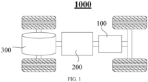
- FIG. 1 is a schematic structural diagram of a vehicle 1000 according to some embodiments of this application.
- the vehicle 1000 may be an oilfueled vehicle, a natural gas vehicle, or a new energy vehicle.
- the new energy vehicle may be a battery electric vehicle, a hybrid electric vehicle, a range-extended electric vehicle, or the like.
- a battery 100 is disposed inside the vehicle 1000.
- the battery 100 may be disposed at the bottom, front, or rear of the vehicle 1000.
- the battery 100 may be configured to supply power to the vehicle 1000.
- the battery 100 may serve as an operating power supply of the vehicle 1000.
- the vehicle 1000 may further include a controller 200 and a motor 300.
- the controller 200 is configured to control the battery 100 to supply power to the motor 300, for example, to meet electrical energy requirements in starting, navigating, or running the vehicle 1000.
- the battery 100 serves not only as an operating power supply of the vehicle 1000, but may also serve as a driving power supply of the vehicle 1000 to provide driving power for the vehicle 1000 in place of or partly in place of fuel oil or natural gas.
- FIG. 2 is a schematic structural diagram of a battery 100 according to an embodiment of this application.
- the battery 100 may include a plurality of battery cells 20.
- the battery 100 may further include a box 10 (or referred to as a casing) in addition to the battery cell.
- the box 10 is hollowed out inside.
- a plurality of battery cells 20 are accommodated in the box 10.
- the box 10 may include two parts, herein referred to as a first part 111 and a second part 112 respectively.
- the first part 111 and the second part 112 are snap-fitted together.
- the shapes of the first part 111 and the second part 112 may depend on the shape of a plurality of battery cells 20 combined.
- first part 111 and the second part 112 each may be a hollow cuboid, and each may include one opened surface.
- the opening of the first part 111 is opposite to the opening of the second part 112.
- the first part 111 and the second part 112 are snap-fitted to each other to form a box 10 that includes a closed cavity.
- the plurality of battery cells 20 are combined and connected in parallel, series, or series-and-parallel pattern, and then placed into the box that is formed by snap-fitting the first part 111 and the second part 112.
- the battery 100 may contain a plurality of battery cells 20.
- the plurality of battery cells 20 may be connected in series, parallel, or series-and-parallel pattern.
- the series-and-parallel pattern means a combination of series connection and parallel connection of the plurality of battery cells 20.
- the plurality of battery cells 20 may be directly connected in series, parallel, or series-and-parallel pattern, and then the whole of the plurality of battery cells 20 may be accommodated in the box.
- the plurality of battery cells 20 may be connected in series, parallel, or series-and-parallel pattern to form a battery module first, and then a plurality of battery modules are connected in series, parallel, or series-and-parallel pattern to form a whole and accommodated in the box.
- the battery 100 may further include other structures.
- the battery 100 may further include a busbar component (not shown in the drawing). The busbar component is configured to implement an electrical connection between the plurality of battery cells 20.
- Each battery cell 20 may be, but is not limited to, a secondary battery or primary battery; or, may be a lithium-sulfur battery, a sodium-ion battery, or a magnesium-ion battery.
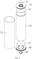
- FIG. 3 is a schematic exploded view of a battery cell according to an embodiment of this application; and FIG. 4 is a schematic structural diagram of a battery cell 20 according to another embodiment of this application.
- the battery cell 20 may include a first sealing element 21, an end cap 22, a negative electrode connection strap 23, an electrode assembly 24, a housing 25, a positive electrode connection strap 27, a bottom cover 28, and a second sealing element 29.
- the housing 25 combines with the first sealing element 21 and the second sealing element 29 to form a shell or a battery case.
- the wall of the housing 25 and the walls of the first sealing element 21 and the second sealing element 29 are all referred to as walls of the battery cell 20.
- the shape of the housing 25 depends on the shape of one or more electrode assemblies 24 combined together.
- an end face of the housing 25 may be an opened face. That is, this end face is not walled so that the inside of the housing 25 communicates with the outside.
- the housing 25 of the cylindrical cell 20 includes two circular end faces. The part between the two circular end face is a cylinder body.
- the cylinder body may include an electrode assembly 24.
- the end cap 22 and the bottom cover 27 cover an upper opening and a lower opening respectively and are connected to the housing 25, and, through the first sealing element 21 and the second sealing element 29, form a closed cavity configured to accommodate the electrode assembly 24.
- the housing 25 is filled with an electrolyte such as an electrolyte solution.
- the battery cell 20 further includes electrode terminals 26.
- the electrode terminals 26 are inserted into the end cap 22 and the bottom cover 28 respectively to get electrically connected to the first sealing element 21 and the second sealing element 29 respectively. More specifically, the electrode terminal 26 includes a first electrode terminal 261 and a second electrode terminal 262. The first electrode terminal 261 is opposite to the second electrode terminal 262.
- the battery cell 20 may further include a current collecting component, configured to electrically connect the electrode assembly 24 to the electrode terminal 26.
- each electrode assembly 24 includes two tabs, such as a first tab and a second tab.
- the first tab and the second tab are of opposite polarities. For example, when the first tab is a positive tab, the second tab is a negative tab.
- the first tab is a copper tab, and the second tab is an aluminum tab.
- the first tabs of one or more electrode assemblies 24 are connected to one electrode terminal 26 by one current collecting component, and the second tabs of one or more electrode assemblies 24 are connected to another electrode terminal 26 by another current collecting component.
- the first tab and the second tab of the battery cell 20 are disposed at two ends respectively.
- the first tab is a copper tab
- the second tab is an aluminum tab.
- the bottom cover 28 may be omitted in the battery cell 20.
- the aluminum tab may be directly connected to the second sealing element 29.
- one or more electrode assemblies 24 may be disposed depending on actual use requirements. As shown in FIG. 4 , one electrode assembly 24 is disposed in the battery cell 20.
- FIG. 5 is a schematic exploded view of an end cap 22 according to an embodiment of this application.
- the end cap 22 includes: an end cap body 221, where a hole 222 is created on the end cap body 221; a first connection structure 223, including a first metal, where the first connection structure 223 is disposed on an outer side of the hole 222 and configured to be welded to an electrode terminal 26 located in the hole 222; and a second connection structure 224, including a second metal.
- the second connection structure 224 is connected to the first connection structure 223.
- the second connection structure 224 is configured to be welded to a first sealing element 21 designed for sealing the hole 222.
- the end cap 22 may further include an upper plastic sheet 225, an end cap strip 226, a sealing ring 227, and a lower plastic sheet 228.
- the electrode terminal 26 passes through the hole 222 to get connected to the end cap 22.
- the electrode terminals 26 are a component used for electrical connection.
- the current generated by the electrode assembly 24 is transmitted to the positive and negative electrodes of the battery cell 20 through the electrode terminals 26.
- the first electrode terminal 261 is connected to the end cap 22.
- the first electrode terminal 261 is electrically connected to the copper tab.
- the current generated by the electrode assembly 24 is transmitted to the end cap 22 through the first electrode terminal 261 at one end, and then transmitted to the first sealing element 21 and is transmitted to the second sealing element 29 at the second electrode terminal 262 through the second electrode terminal 262 at the other end.
- Both the first sealing element 21 and the second sealing element 29 are connected to the busbar component. In this way, the current can flow directly from the electrode assembly 24 to the outside, without passing through the housing 25 of the battery cell 20.
- the first connection structure 223 needs to be connected to the first electrode terminal 261 by welding. If the first connection structure 223 is connected to the first electrode terminal 261 by other means, then the internal resistance between the first connection structure and the first electrode terminal will be relatively large, thereby still causing current loss of the battery cell 20. Therefore, the first metal included in the first connection structure 223 is necessarily a metal that can be welded to the first electrode terminal 261.
- the hole 222 serves to accommodate the first electrode terminal 261. Therefore, the size of the hole 222 needs to be set depending on the size of the electrode assembly 24 or the first electrode terminal 261. This application does not impose any limitation on the specific size of the hole 222.
- the end cap 22 includes an end cap body 221, a first connection structure 223, and a second connection structure 224.
- the end cap body 221 includes a hole 222.
- the hole 222 is configured to accommodate the first electrode terminal 261.
- the first connection structure 223 is located on the inner side of the hole 222, and is welded to the first electrode terminal 261. That is, the first connection structure 223 is contiguous to the hole 222.
- the second connection structure 224 is connected to the first connection structure 223, and is welded to the first sealing element 21 designed for sealing the hole 222.
- connection structure 223 When the first connection structure 223 is connected to the second connection structure 224, electrical connection is implemented between the first connection structure 223 and the second connection structure 224.
- first sealing element 21 When the first sealing element 21 is connected to the second connection structure 224, electrical connection is implemented between the second connection structure 224 and the first sealing element 21.
- this application enables a current to flow directly from the first electrode terminal 261 to the first sealing element 21, and then causes the current to flow to a busbar component connected to the first sealing element 21, thereby avoiding the current loss caused by the need to pass through the housing 25 of the battery, and in turn, increasing the output current of the battery cell 20 and improving the performance of the battery 100.
- FIG. 6 is a cross-sectional view of an end cap 22 according to an embodiment of this application.
- FIG. 7 is a close-up view of a region A shown in FIG. 6 .
- the end cap body 221 includes a first step structure 2211 disposed at an edge of the hole 222.
- the first step structure 2211 is configured to be embedded into the first connection structure 223.
- the first connection structure 223 can be positioned on the inner side of the hole 221, so as to enable welding of the first connection structure 223 to the first electrode terminal 261 located in the hole 221.
- both the inner side of the hole 222 and the edge of the hole 222 are regions that are not physically isolated from the hole 222, but are connected to the hole 222.
- this application connects the first connection structure 223 to the first electrode terminal 261 located in the hole 222, and in turn, allows the current to flow directly from the first electrode terminal 261 to the first connection structure 223.
- the end cap body 221 further includes a second step structure 2212.
- the second step structure 2212 is closer to the inner side of the hole 222 than the first step structure 2211.
- the second step structure 2212 is configured to lap the first electrode terminal 261.
- the first electrode terminal 261 is located in the hole 222.
- a second step structure 2212 is further disposed in the end cap body 221. Further, the second step structure 2212 is closer to the inner side of the hole 222 than the first step structure 2211. That is, the second step structure 2212 is also contiguous to the hole 222. In other words, the second step structure 2212 is connected to the hole 222.
- the second step structure 2212 is configured to lap the first electrode terminal 261, thereby enabling connection of the first electrode terminal 261 to the first connection structure 223 on the first step structure 2211.
- this application can place the first electrode terminal 261 stably in the hole 222 and connect the first electrode terminal to the first connection structure 223 stably, thereby implementing a stable flow of current.
- the first connection structure 223 includes a third step structure 2213.
- the third step structure 2213 is configured to leave a clearance for a welding structure 2214 of the first connection structure 223 and the first electrode terminal 261.
- the first connection structure 223 located in the first step structure 2211 is welded to the first electrode terminal 261 lapped in the second step structure 2212.
- Some welding structures 2214 such as weld marks, may result from the welding between the first connection structure and the electrode terminal, thereby causing the surface of the first connection structure 223 to be uneven. If the uneven surface of the first connection structure 223 is in direct contact with other components, the normal use of the other components will be adversely affected.
- the second connection structure 224 also needs to be welded to the first sealing element 21.
- the first sealing element 21 is in contact with the surface of the first connection structure 223.
- the welding structure may interfere with the welding or normal use of the end cap 22.
- the end cap body 221, the first connection structure 223, and the second connection structure 224 are all annular.
- the current is transmitted to the first electrode terminal 261 first, and then transmitted to the first connection structure 223 by the first electrode terminal 261, and then transmitted to the second connection structure 224 by the first connection structure 223, and then transmitted to the first sealing element 21 by the second connection structure 224, and finally transmitted to other external components such as a busbar component by the first sealing element 21, thereby enabling a plurality of battery cells 20 to form an electrically connected battery module. Therefore, theoretically, the technical solution works as long as the parts that need to transmit the current are set to be the first connection structure 223 and the second connection structure 224, respectively. However, in order to transmit the current more efficiently, both the first connection structure 223 and the second connection structure 224 may be made to be annular. Nevertheless, in practical applications, the producer may dispose the corresponding parts based on the actual production requirements. This application does not limit the specific positions of the first connection structure 223 and the second connection structure 224 and the like in the end cap 22.
- the end cap body 221, the first connection structure 223, and the second connection structure 224 are all annular, the first connection structure 223 and the second connection structure 224 are distributed in the end cap 22 as much as practicable and reasonable, so as to implement smooth transmission of an electric current.
- FIG. 8 is a close-up view of a region B shown in FIG. 7 .
- a dimension D1 of the first connection structure 223 is 0.8 to 1 mm, and the first direction X is parallel to an axis of the end cap 22.
- the first connection structure 223 is not only connected to the second connection structure 224, but also welded to the first electrode terminal 261 located in the hole 222.
- the welding between the first connection structure 223 and the first electrode terminal 261 may be weak.
- the dimension D1 of the first connection structure 223 in the first direction X may be 0.85 mm, 0.9 mm, 1 mm, or the like.
- the value of D1 is not particularly limited herein, as long as the engineering requirements are satisfied.
- the connection between the first connection structure 223 and the first electrode terminal 261 is ensured to be firm, and a stable flow of current is achieved.
- a dimension D2 of the second connection structure 224 is 2 to 4 mm.
- the dimension D2 of the second connection structure 224 in the first direction X may be 2 mm, 3 mm, 3.5 mm, 4 mm, or the like.
- the value of D3 is not particularly limited herein, as long as the engineering requirements are satisfied.
- the second connection structure 224 is not only connected to the first connection structure 223, but also connected to the first sealing element 21 designed for sealing the hole 222.
- the welding between the second connection structure 224 and the first sealing element 21 may be weak.
- the connection between the second connection structure 224 and the first sealing element 21 is ensured to be firm, and a stable flow of current is achieved.
- a dimension D3 of the third step structure 2213 is not less than 0.2 mm.
- the dimension D3 of the third step structure 2213 in the first direction X may be 0.2 mm, 0.3 mm, 0.35 mm, 0.4 mm, or the like.
- the value of D3 is not particularly limited herein, as long as the engineering requirements are satisfied.
- the third step structure 2213 is configured to leave a clearance for the welding structure 2214 of the first connection structure 223 and the first electrode terminal 261, so as to ensure normal use of other components around the first connection structure 223 and the first electrode terminal 261.
- a dimension D4 of the first connection structure 223 on one side of the axis of the first sealing element 21 is not less than 1 mm.
- the second direction Y is perpendicular to the axis of the end cap 22.
- the dimension D1 of the first connection structure 223 in the first direction X needs to meet the specified requirement.
- the first connection structure 223 not only needs to be connected to the first electrode terminal 261, but also needs to be connected to the second connection structure 224. If the dimension D4 of the first connection structure 223 in the second direction Y is overly small, the connection between the first connection structure and the second connection structure 224 may be inferior.
- the end cap body 221, the first connection structure 223, and the second connection structure 224 are all left-right symmetrical.
- the first connection structures 223 existent on both sides are welded to the first electrode terminal 261 separately. Therefore, on a single side, the dimension D4 of the first connection structure 223 in the second direction Y is not less than 1 mm.
- the dimension D4 of the first connection structure 223 on a single side in the second direction Y may be 1 mm, 1.5 mm, 2 mm, or the like.
- the value of D3 is not particularly limited herein, as long as the engineering requirements are satisfied.
- the first connection structure 223 can be connected to the second connection structure 224 stably, and the electric current can be output stably.
- a dimension D5 of the second connection structure 224 on one side of the axis of the end cap 22 is not less than 5 mm.
- the dimension D4 of the second connection structure 224 on a single side in the second direction Y may be 2 mm, 3 mm, 4 mm, or the like.
- the value of D3 is not particularly limited herein, as long as the engineering requirements are satisfied.
- the second connection structure 224 of an appropriate dimension can perfectly mate with components such as the first electrode terminal 261 and the first sealing element 21. Similarly, the second connection structures 224 existent on both sides are welded to the first sealing element 21 separately. Therefore, on a single side, the dimension D5 of the second connection structure 224 in the second direction Y is not less than 5 mm.
- the electrode terminal 26 is made of a material including copper.
- the first metal is nickel-plated steel or copper.
- the first connection structure 223 needs to be connected to the first electrode terminal 261 by welding. Therefore, the first metal in the first connection structure 223 is necessarily a metal that can be welded to the first electrode terminal 261.
- the electrode terminal 26 more specifically, the first electrode terminal 261 is made of a material including copper, and the first metal in the first connection structure 223 is copper or nickel-plated steel, the copper-containing first electrode terminal 261 can be directly welded to the first connection structure 223.
- the electrode terminal 26 can be directly welded to the first connection structure 223 to transmit the current efficiently and avoid current loss, thereby increasing the current flowing to the outside.
- the first sealing element 21 is made of a material including aluminum.
- the second metal is aluminum.
- the aluminum-containing first sealing element 21 can be directly welded to the second connection structure 224.
- the material of the second sealing element 29 also includes aluminum.
- the electrical connection between the battery cell 20 and the outside can be implemented by the connection between the aluminum-containing first sealing element 21 and the busbar component made of aluminum, thereby reducing the cost of the battery 100 and facilitating use in mass production.
- the second metal in the second connection structure 224 is aluminum, thereby implementing a firm connection between the battery cell 20 and the outside, avoiding current loss, and increasing the current flowing to the outside.
- the first tab in the battery cell 20 is made of copper. Therefore, the material of the electrode terminal 26 connected to the first tab needs to include copper. In other words, the material of the first electrode terminal 261 includes copper.
- the second tab is made of aluminum. Therefore, the material of the electrode terminal 26 connected to the second tab needs to include aluminum. In other words, the material of the second electrode terminal 292 includes aluminum. Referring to FIG. 4 , the first tab is electrically connected to the first electrode terminal 261, the first electrode terminal 261 is electrically connected to the end cap 22, and then the end cap 22 is electrically connected to an external busbar component through the first sealing element 21. The second tab is electrically connected to the second electrode terminal 262, the second electrode terminal 262 is electrically connected to the second sealing element 29, and then the second sealing element 29 is electrically connected to the external busbar component.
- the first connection structure 223 is connected to the second connection structure 224 by thermal bonding.
- Hot rolling is a process of rolling performed above a crystallization temperature.
- the metal is of a high plasticity and a low deformation resistance, thereby greatly reducing the energy consumption during metal deformation.
- the hot rolling process can improve the processing performance of a metal and an alloy. This process crushes cast-state coarse grains, promotes healing of cracks, reduces or eliminates casting defects, changes a cast-state structure into a deformation-induced structure, and improves the processing performance of the alloy.
- copper and aluminum are bonded together at the crystallization temperatures of copper and aluminum.
- the end cap 22 structure connected by thermal bonding possesses a relatively low internal resistance.
- the current can be more efficiently transferred from the first connection structure 223 to the second connection structure 224 to implement transfer of a relatively large current between the battery cell 20 and the outside, thereby improving the performance of the battery 100.
- An embodiment of this application further provides a battery cell 20.
- the battery cell 20 includes: an electrode assembly 24; a housing 25 with a first opening, configured to accommodate the electrode assembly 24; the end cap 22 according to any one of the foregoing embodiments, where the end cap includes a second opening, and the end cap 22 is configured to seal the first opening; and a first sealing element 21, configured to seal the second opening.
- the first sealing element 21 in a first direction X, includes a protruding portion 211 relative to the end cap 22.
- the first direction X is parallel to an axis of the end cap 22.
- the second connection structure 224 is welded to the first sealing element 21 designed for sealing the hole 222 of the end cap body 221.
- Some welding structures 2214 such as weld marks, may result from the welding between the second connection structure and the first sealing element, thereby causing the surface of the second connection structure 224 to be uneven.
- the first sealing element 21 also needs to be connected to the busbar component. If the uneven surface of the second connection structure 224 is in direct contact with the busbar component, the normal use of the busbar component will be adversely affected.
- the busbar component or other components can stay clear from the welding structure 2214 of the second connection structure 224 and the first sealing element 21, thereby ensuring the normal use of the busbar component or other components.
- a dimension D6 of the protruding portion 211 is not less than 0.2 mm.
- the protruding portion 211 located on the first sealing element 21 is configured to leave a clearance for the welding structure 2214 of the second connection structure 224 and the first sealing element 21, so as to ensure normal use of other components around the second connection structure 224 and the first sealing element 21.
- the dimension of the protruding portion 211 in the first direction X may be 0.2 mm, 0.25 mm, or 0.3 mm.
- the value of the dimension is not particularly limited herein, as long as the engineering requirements are satisfied.
- the battery cell 20 includes two types of electrode terminals 26: a copper-containing first electrode terminal 261, and an aluminum-containing second electrode terminal 262.
- the two types of electrode terminals 26 are disposed at two ends of the battery cell 20 respectively.
- the first electrode terminal 261 is connected to a copper tab
- the second electrode terminal 262 is connected to an aluminum tab.
- the first electrode terminal 261 is connected to the end cap 22, and then connected to an external busbar component through the first sealing element 21.
- the second electrode terminal 262 is connected to the bottom cover 28, and then connected to the external busbar component through the second sealing element 29.
- An embodiment of this application further provides a battery 100.
- the battery includes the battery cell 20 disclosed in the preceding embodiment.
- An embodiment of this application further provides an electrical device.
- the electrical device may include the battery 100 according to any one of the foregoing embodiments, and the battery is configured to provide electrical energy for the electrical device.
- the electrical device may be a vehicle, watercraft, or spacecraft.
- the first electrode terminal 261 and the second electrode terminal 262 are disposed opposite to each other at two ends of the battery cell 20.
- the first electrode terminal 261 connected to the first tab (that is, the copper tab) is connected to the end cap 22 containing the first connection structure 223 and the second connection structure 224, and is then connected to the first sealing element 21.
- the second electrode terminal 262 connected to the second tab (that is, the aluminum tab) is connected to the second sealing element 29, thereby transmitting the current generated by the electrode assembly 24 to the outside directly, avoiding current loss caused by the need to pass through the housing 25, and in turn, increasing the output current of the battery cell 20 and improving the performance of the battery 100.
Landscapes
- Chemical & Material Sciences (AREA)
- Chemical Kinetics & Catalysis (AREA)
- Electrochemistry (AREA)
- General Chemical & Material Sciences (AREA)
- Inorganic Chemistry (AREA)
- Connection Of Batteries Or Terminals (AREA)
- Sealing Battery Cases Or Jackets (AREA)
Abstract
Description
- This application relates to the technical field of batteries, and in particular, to an end cap, a battery cell, a battery, and an electrical device.
- With the aggravation of environmental pollution, the new energy industry is attracting more and more attention. Battery technology is crucial to the development of the new energy industry.
- In the development of battery technology, how to enhance the performance of a battery is a pressing challenge in the battery technology.
- In view of the above situation, some embodiments of this application provide an end cap, a battery cell, a battery, and an electrical device to increase an output current of the battery, and in turn, improve performance of the battery.
- According to a first aspect, an end cap is provided. The end cap includes: an end cap body, where a hole is created on the end cap body; a first connection structure, including a first metal, where the first connection structure is disposed on an inner side of the hole and configured to be welded to an electrode terminal located in the hole; and a second connection structure, including a second metal. The second connection structure is connected to the first connection structure. The second connection structure is configured to be welded to a first sealing element designed for sealing the hole.
- In an embodiment of this application, the end cap includes an end cap body, a first connection structure, and a second connection structure. The end cap body includes a hole. The hole is configured to accommodate the electrode terminal. The first connection structure is located on the inner side of the hole, and is welded to the electrode terminal. That is, the first connection structure is contiguous to the hole. The second connection structure is connected to the first connection structure, and is welded to the first sealing element designed for sealing the hole. By disposing the first connection structure and the second connection structure, connecting the first connection structure to the electrode terminal, connecting the first connection structure to the second connection structure, and connecting the second connection structure to the first sealing element, this application enables a current to flow directly from the electrode terminal to the first sealing element, and then causes the current to flow to an external circuit connected to the first sealing element, thereby avoiding the current loss caused by the need to pass through the housing of the battery, and in turn, increasing the output current of the battery and improving the performance of the battery.
- In a possible embodiment, the end cap body includes a first step structure disposed at an edge of the hole. The first step structure is configured to be embedded into the first connection structure.
- In this embodiment of this application, when the first step structure is disposed at the edge of the hole and the first connection structure is embedded in the first step structure, the first connection structure can be positioned on the inner side of the hole, so as to enable welding of the first connection structure to the electrode terminal located in the hole. By disposing at the edge of the hole the first step structure for being embedded into the first connection structure, this application connects the first connection structure to the electrode terminal located in the hole, and in turn, allows the current to flow directly from the electrode terminal to the first connection structure.
- In a possible embodiment, the end cap body further includes a second step structure. The second step structure is closer to the inner side of the hole than the first step structure. The second step structure is configured to lap the electrode terminal.
- In this embodiment of this application, the electrode terminal is located in the hole. A second step structure is further disposed in the end cap body. Further, the second step structure is closer to the inner side of the hole than the first step structure. That is, the second step structure is also contiguous to the hole. The second step structure is configured to lap the electrode terminal, thereby enabling connection of the electrode terminal to the first connection structure in the first step structure. By disposing in the end cap body the second step structure configured to lap the electrode terminal, and letting the second step structure be closer to the inner side of the hole than the first step structure, this application can place the electrode terminal stably in the hole and connect the electrode terminal to the first connection structure stably, thereby implementing a stable flow of current.
- In a possible embodiment, the first connection structure includes a third step structure. The third step structure is configured to leave a clearance for a welding structure of the first connection structure and the electrode terminal.
- In this embodiment of this application, the first connection structure located in the first step structure is welded to the electrode terminal lapped in the second step structure. Some welding structures, such as weld marks, may result from the welding between the first connection structure and the electrode terminal, thereby causing the surface of the first connection structure to be uneven. If the uneven surface of the first connection structure is in direct contact with other components, the normal use of the other components will be adversely affected. By disposing a third step structure in the first connection structure, other components can stay clear from the welding structure of the first connection structure and the electrode terminal, thereby ensuring the normal use of other components.
- In a possible embodiment, the end cap body, the first connection structure, and the second connection structure are all annular.
- In this embodiment of this application, by designing the end cap body, the first connection structure, and the second connection structure to be all annular, the first connection structure and the second connection structure are distributed in the end cap as much as practicable and reasonable, so as to implement smooth transmission of an electric current.
- In a possible embodiment, in a first direction, a dimension of the first connection structure is 0.8 to 1 mm, and the first direction is parallel to an axis of the end cap.
- In this embodiment of this application, the first connection structure is not only connected to the second connection structure, but also welded to the electrode terminal located in the hole. When the dimension of the first connection structure in the first direction is overly small, the welding between the first connection structure and the electrode terminal may be weak. By keeping the dimension of the first connection structure in the first direction within the range of 0.8 to 1 mm, the connection between the first connection structure and the electrode terminal is ensured to be firm, and a stable flow of current is achieved.
- In a possible embodiment, in the first direction, a dimension of the second connection structure is 2 to 4 mm.
- In this embodiment of this application, the second connection structure is not only connected to the first connection structure, but also connected to the first sealing element designed for sealing the hole. When the dimension of the second connection structure in the first direction is overly small, the welding between the second connection structure and the first sealing element may be weak. By keeping the dimension of the second connection structure in the first direction within the range of 2 to 4 mm, the connection between the second connection structure and the first sealing element is ensured to be firm, and a stable flow of current is achieved.
- In a possible embodiment, in the first direction, a dimension of a third step structure is not less than 0.2 mm.
- In this embodiment of this application, the third step structure is configured to leave a clearance for the welding structure of the first connection structure and the electrode terminal, so as to ensure normal use of other components around the first connection structure and the electrode terminal. By making the dimension of the third step structure in the first direction not less than 0.2 mm, other components are ensured to completely stay clear from the welding structure of the first connection structure and the electrode terminal, thereby further ensuring that the current can directly flow from the electrode terminal to the first sealing element.
- In a possible embodiment, in a second direction, a dimension of the first connection structure on one side of an axis of the end cap is not less than 1 mm, and the second direction is perpendicular to the axis of the end cap.
- In this embodiment of this application, in order to ensure a firm weld between the first connection structure and the electrode terminal, the dimension of the first connection structure in the first direction needs to meet the specified requirement. However, the first connection structure not only needs to be connected to the electrode terminal, but also needs to be connected to the second connection structure. If the dimension of the first connection structure in the second direction is overly small, the connection between the first connection structure and the second connection structure may be inferior. By making the dimension of the first connection structure on a single side in the second direction not less than 1 mm, the first connection structure can be connected to the second connection structure stably, and the electric current can be output stably.
- In a possible embodiment, in the second direction, a dimension of the second connection structure on one side of the axis of the end cap is not less than 5 mm.
- In this embodiment of this application, the second connection structure of an appropriate dimension can perfectly mate with components such as the electrode terminal and the end cap. By making the dimension of the second connection structure on a single side in the second direction not less than 5 mm, normal functionality of the end cap can be ensured.
- In a possible embodiment, the electrode terminal is made of a material including copper. The first metal is nickel-plated steel or copper.
- In this embodiment of this application, when the electrode terminal includes copper and the first metal in the first connection structure is copper or nickel-plated steel, the copper-containing electrode terminal can be directly welded to the first connection structure. By making the first metal in the first connection structure be copper or nickel-plated steel, the electrode terminal can be directly welded to the first connection structure to transmit a current efficiently and avoid current loss, thereby increasing the current flowing to the outside.
- In a possible embodiment, the first sealing element is made of a material including aluminum. The second metal is aluminum.
- In this embodiment of this application, when the first sealing element includes aluminum and the second metal in the second connection structure is aluminum, the aluminum-containing first sealing element can be directly welded to the second connection structure. Aluminum is cheap and easily available. The electrical connection between the battery and the outside can be implemented by the connection between the aluminum-containing end cap the busbar component made of aluminum, thereby reducing the cost of the battery and facilitating use in mass production. In addition, the second metal in the second connection structure is aluminum, thereby implementing a firm connection between the battery and the outside, avoiding current loss, and increasing the current flowing to the outside.
- In a possible embodiment, the first connection structure is connected to the second connection structure by thermal bonding.
- In this embodiment of this application, the end cap structure connected by thermal bonding possesses a relatively low internal resistance. In other words, when the first connection structure is connected to the second connection structure by thermal bonding, the current can be more efficiently transferred from the first connection structure to the second connection structure to implement transfer of a relatively large current between the battery and the outside, thereby improving performance of the battery.
- According to a second aspect, a battery cell is provided, including: an electrode assembly; a housing with a first opening, configured to accommodate the electrode assembly; the end cap according to any one of the foregoing embodiments, where the end cap includes a second opening, and the end cap is configured to seal the first opening; and the first sealing element, configured to seal the second opening.
- In a possible embodiment, in a first direction, the first sealing element includes a protruding portion relative to the end cap. The first direction is parallel to an axis of the end cap.
- In this embodiment of this application, the second connection structure is welded to a connecting piece designed for sealing the hole of the end cap body. Some welding structures, such as weld marks, may result from the welding between the second connection structure and the connecting piece, thereby causing the surface of the second connection structure to be uneven. The first sealing element also needs to be connected to the busbar component. If the uneven surface of the second connection structure is in direct contact with the busbar component, the normal use of the busbar component will be adversely affected. By disposing a protruding portion on the first sealing element, the busbar component or other components can stay clear from the welding structure of the second connection structure and the first sealing element, thereby ensuring the normal use of the busbar component or other components.
- In a possible embodiment, in the first direction, a dimension of the protruding portion is not less than 0.2 mm.
- In this embodiment of this application, the protruding portion located on the first sealing element is configured to leave a clearance for the welding structure of the second connection structure and the first sealing element, so as to ensure normal use of other components around the second connection structure and the first sealing element. By making the dimension of the protruding portion in the first direction not less than 0.2 mm, other components are ensured to completely stay clear from the welding structure of the second connection structure and the first sealing element, thereby further ensuring that the current can directly flow from the electrode terminal to the first sealing element and then flow to the outside.
- According to a third aspect, a battery is provided. The battery includes: a plurality of the battery cells according to the foregoing embodiment; and a busbar component, configured to electrically connect the plurality of battery cells.
- According to a fourth aspect, this application provides an electrical device. The electrical device includes the battery disclosed in the foregoing embodiment. The battery is configured to provide electrical energy.
- To describe the technical solutions of some embodiments of this application more clearly, the following outlines the drawings used in the embodiments of this application. Evidently, the drawings outlined below are merely a part of embodiments of this application. A person of ordinary skill in the art may derive other drawings from the outlined drawings without making any creative efforts.
-
FIG. 1 is a schematic structural diagram of a vehicle according to an embodiment of this application; -
FIG. 2 is a schematic exploded view of a battery according to an embodiment of this application; -
FIG. 3 is a schematic exploded view of a battery cell according to an embodiment of this application; -
FIG. 4 is a schematic structural diagram of a battery cell according to another embodiment of this application; -
FIG. 5 is a schematic exploded view of an end cap according to an embodiment of this application; -
FIG. 6 is a cross-sectional view of an end cap according to an embodiment of this application; -
FIG. 7 is a close-up view of a region A shown inFIG. 6 ; and -
FIG. 8 is a close-up view of a region B shown inFIG. 7 . - List of reference numerals:
-
battery 100,first part 111,second part 112,controller 200,motor 300; - box 10,
battery cell 20, first sealingelement 21,end cap 22, negativeelectrode connection strap 23,electrode assembly 24,housing 25,electrode terminal 26, positiveelectrode connection strap 27,bottom cover 28,second sealing element 29; -
end cap body 221,hole 222,first connection structure 223,second connection structure 224, upper plastic sheet 265, end cap strip 266, sealing ring 267, lower plastic sheet 268,first electrode terminal 261,second electrode terminal 262; -
first step structure 2211,second step structure 2212,third step structure 2213,welding structure 2214, first direction X, second direction Y - To make the objectives, technical solutions, and advantages of the embodiments of this application clearer, the following gives a clear description of the technical solutions in the embodiments of this application with reference to the drawings in the embodiments of this application. Evidently, the described embodiments are merely a part of but not all of the embodiments of this application. All other embodiments derived by a person of ordinary skill in the art based on the embodiments of this application without making any creative effort fall within the protection scope of this application.
- In the description of this application, unless otherwise specified, "a plurality of" means at least two in number; the terms such as "up", "down", "left", "right", "in", and "out" indicating a direction or a position relationship are merely intended for ease or brevity of description of this application, but do not indicate or imply that the mentioned device or component is necessarily located in the specified direction and position or constructed or operated in the specified direction and position. Therefore, such terms are not to be understood as a limitation on this application. In addition, the terms "first", "second", "third", and so on are merely used for descriptive purposes, but not construed as indicating or implying relative importance. "Perpendicular" does not means exact perpendicularity, but means perpendicularity falling within an error tolerance range. "Parallel" does not mean exact parallelism, but means parallelism falling within an error tolerance range.
- The directional terms appearing in the following description indicate the directions shown in the drawings, but are not intended to limit specific structures in this application. In the description of this application, unless otherwise expressly specified, the terms "mount", "concatenate", and "connect" are understood in a broad sense. For example, a "connection" may be a fixed connection, a detachable connection, or an integrated connection, and may be a direct connection or an indirect connection implemented through an intermediary. A person of ordinary skill in the art can understand the specific meanings of the terms in this application according to specific situations.
- In this application, the term "and/or" merely indicates a relationship between related items, and represents three possible relationships. For example, "A and/or B" may represent the following three circumstances: A alone, both A and B, and B alone. In addition, the character "/" herein generally indicates an "or" relationship between the item preceding the character and the item following the character.
- Unless otherwise defined, all technical and scientific terms used herein have the same meanings as what is normally understood by a person skilled in the technical field of this application. The terms used in the specification of this application are merely intended to describe specific embodiments but not intended to limit this application. The terms "include" and "contain" and any variations thereof used in the specification, claims, and brief description of drawings of this application are intended as non-exclusive inclusion.
- Reference to "embodiment" in this application means that a specific feature, structure or characteristic described with reference to the embodiment may be included in at least one embodiment of this application. Reference to this term in different places in the specification does not necessarily represent the same embodiment, nor does it represent an independent or alternative embodiment in a mutually exclusive relationship with other embodiments. A person skilled in the art explicitly and implicitly understands that an embodiment described in this application may be combined with another embodiment.
- The battery in some embodiments of this application may be a lithium-ion battery, a lithium metal battery, a lead-acid battery, a nickel-cadmium battery, a nickelhydrogen battery, a lithium-sulfur battery, a lithium-air battery, a sodium-ion battery, or the like. The type of the battery is not particularly limited herein.
- To meet different power demands, a plurality of battery cells in a battery may be connected in series, parallel, or series-and-parallel pattern. The series-and-parallel pattern means a combination of series connection and parallel connection. Optionally, the plurality of battery cells may be connected in series, parallel, or series-and-parallel pattern to form a battery module, and then a plurality of battery modules may be connected in series, parallel, or series-and-parallel pattern to form the battery. In other words, the plurality of battery cells may directly form the battery, or form the battery modules that are then used to form the battery. The battery is further mounted in the electrical device to provide electrical energy for the electrical device.
- Currently, the market trend shows that power batteries are applied in more and more fields. Power batteries are not only used in energy storage power systems such as hydro, thermal, wind, and solar power stations, but also widely used in electric means of transport such as electric bicycles, electric motorcycles, and electric vehicles, and used in many other fields such as military equipment and aerospace. The market demand for power batteries keeps soaring with the increase of the application fields of the power batteries.
- The applicant hereof has noticed that an existing cylindrical battery typically includes only one electrode terminal, and a material that is used on the cell for connecting to a busbar component of an external module is nickel-plated steel and aluminum. The busbar component of the module is mostly made of an aluminum bar, a nickel sheet, or a nickel-plated material. Therefore, when a current is generated inside the cylindrical battery, the current needs to pass through the housing of the cylindrical battery. The internal resistance of the housing is relatively high, thereby causing the output current of the cylindrical battery to be smaller, and in turn, causing a decline in the performance of the cylindrical battery.
- In order to solve the problem of inferior performance of existing cylindrical batteries caused by the inability of the batteries to output a relatively large current, An embodiment of this application provides an end cap. With the end cap, a cylindrical battery fitted with two electrode terminals enables both the positive electrode terminal and the negative electrode terminal to be electrically connected to a busbar component directly. In this way, the current can flow from the electrode terminals to the end cap directly, and then flow to the first sealing element connected to the end cap without a need to pass through the housing of the battery cell, thereby increasing the output current of the battery cell and improving the performance of the battery.
- It is hereby noted that the end cap provided in this application is applicable to, but not limited to use in, cylindrical batteries, especially the 4680 structure of cylindrical batteries.
- The battery cell disclosed in embodiments of this application is applicable to, but not limited to use in, electrical devices such as a vehicle, watercraft, or aircraft. The battery cell, the battery, and the like disclosed in this application may be used to form a power supply system of the electrical device to increase the current of the cylindrical battery in the power supply system and improve performance of the cylindrical battery.
- All technical solutions described herein are applicable to various battery-powered devices such as a mobile phone, a portable device, a laptop computer, an electric power cart, an electrical toy, an electric tool, an electric vehicle, a watercraft, and a spacecraft. The electric toy may include stationary or mobile electric toys, such as a game console, an electric car toy, an electric ship toy, and an electric airplane toy. The spacecraft may include an airplane, a rocket, a space shuttle, a spaceship, and the like.
- Understandably, the technical solutions described in the embodiments of this application are not only applicable to the devices mentioned above, but also applicable to all battery-powered devices. However, for brevity, the following embodiments are described by using an electric vehicle as an example.
- For example,
FIG. 1 is a schematic structural diagram of avehicle 1000 according to some embodiments of this application. Thevehicle 1000 may be an oilfueled vehicle, a natural gas vehicle, or a new energy vehicle. The new energy vehicle may be a battery electric vehicle, a hybrid electric vehicle, a range-extended electric vehicle, or the like. Abattery 100 is disposed inside thevehicle 1000. Thebattery 100 may be disposed at the bottom, front, or rear of thevehicle 1000. Thebattery 100 may be configured to supply power to thevehicle 1000. For example, thebattery 100 may serve as an operating power supply of thevehicle 1000. Thevehicle 1000 may further include acontroller 200 and amotor 300. Thecontroller 200 is configured to control thebattery 100 to supply power to themotor 300, for example, to meet electrical energy requirements in starting, navigating, or running thevehicle 1000. - In some embodiments of this application, the
battery 100 serves not only as an operating power supply of thevehicle 1000, but may also serve as a driving power supply of thevehicle 1000 to provide driving power for thevehicle 1000 in place of or partly in place of fuel oil or natural gas. - For example,
FIG. 2 is a schematic structural diagram of abattery 100 according to an embodiment of this application. Thebattery 100 may include a plurality ofbattery cells 20. Thebattery 100 may further include a box 10 (or referred to as a casing) in addition to the battery cell. The box 10 is hollowed out inside. A plurality ofbattery cells 20 are accommodated in the box 10. As shown inFIG. 2 , the box 10 may include two parts, herein referred to as afirst part 111 and asecond part 112 respectively. Thefirst part 111 and thesecond part 112 are snap-fitted together. The shapes of thefirst part 111 and thesecond part 112 may depend on the shape of a plurality ofbattery cells 20 combined. An opening may be created on both thefirst part 111 and thesecond part 112. For example, thefirst part 111 and thesecond part 112 each may be a hollow cuboid, and each may include one opened surface. The opening of thefirst part 111 is opposite to the opening of thesecond part 112. Thefirst part 111 and thesecond part 112 are snap-fitted to each other to form a box 10 that includes a closed cavity. The plurality ofbattery cells 20 are combined and connected in parallel, series, or series-and-parallel pattern, and then placed into the box that is formed by snap-fitting thefirst part 111 and thesecond part 112. - The
battery 100 may contain a plurality ofbattery cells 20. The plurality ofbattery cells 20 may be connected in series, parallel, or series-and-parallel pattern. The series-and-parallel pattern means a combination of series connection and parallel connection of the plurality ofbattery cells 20. The plurality ofbattery cells 20 may be directly connected in series, parallel, or series-and-parallel pattern, and then the whole of the plurality ofbattery cells 20 may be accommodated in the box. Alternatively, to make up abattery 100, the plurality ofbattery cells 20 may be connected in series, parallel, or series-and-parallel pattern to form a battery module first, and then a plurality of battery modules are connected in series, parallel, or series-and-parallel pattern to form a whole and accommodated in the box. Thebattery 100 may further include other structures. For example, thebattery 100 may further include a busbar component (not shown in the drawing). The busbar component is configured to implement an electrical connection between the plurality ofbattery cells 20. - Each
battery cell 20 may be, but is not limited to, a secondary battery or primary battery; or, may be a lithium-sulfur battery, a sodium-ion battery, or a magnesium-ion battery. -
FIG. 3 is a schematic exploded view of a battery cell according to an embodiment of this application; andFIG. 4 is a schematic structural diagram of abattery cell 20 according to another embodiment of this application. As shown inFIG. 3 andFIG. 4 , thebattery cell 20 may include afirst sealing element 21, anend cap 22, a negativeelectrode connection strap 23, anelectrode assembly 24, ahousing 25, a positiveelectrode connection strap 27, abottom cover 28, and asecond sealing element 29. Thehousing 25 combines with thefirst sealing element 21 and thesecond sealing element 29 to form a shell or a battery case. The wall of thehousing 25 and the walls of thefirst sealing element 21 and thesecond sealing element 29 are all referred to as walls of thebattery cell 20. The shape of thehousing 25 depends on the shape of one ormore electrode assemblies 24 combined together. When thehousing 25 is a hollow cylinder, an end face of thehousing 25 may be an opened face. That is, this end face is not walled so that the inside of thehousing 25 communicates with the outside. As can be seen fromFIG. 3 , thehousing 25 of thecylindrical cell 20 includes two circular end faces. The part between the two circular end face is a cylinder body. The cylinder body may include anelectrode assembly 24. Theend cap 22 and thebottom cover 27 cover an upper opening and a lower opening respectively and are connected to thehousing 25, and, through thefirst sealing element 21 and thesecond sealing element 29, form a closed cavity configured to accommodate theelectrode assembly 24. Thehousing 25 is filled with an electrolyte such as an electrolyte solution. - The
battery cell 20 further includeselectrode terminals 26. Theelectrode terminals 26 are inserted into theend cap 22 and thebottom cover 28 respectively to get electrically connected to thefirst sealing element 21 and thesecond sealing element 29 respectively. More specifically, theelectrode terminal 26 includes afirst electrode terminal 261 and asecond electrode terminal 262. Thefirst electrode terminal 261 is opposite to thesecond electrode terminal 262. - The
battery cell 20 may further include a current collecting component, configured to electrically connect theelectrode assembly 24 to theelectrode terminal 26. - In addition, each
electrode assembly 24 includes two tabs, such as a first tab and a second tab. The first tab and the second tab are of opposite polarities. For example, when the first tab is a positive tab, the second tab is a negative tab. For another example, the first tab is a copper tab, and the second tab is an aluminum tab. The first tabs of one ormore electrode assemblies 24 are connected to oneelectrode terminal 26 by one current collecting component, and the second tabs of one ormore electrode assemblies 24 are connected to anotherelectrode terminal 26 by another current collecting component. - In an embodiment of this application, the first tab and the second tab of the
battery cell 20 are disposed at two ends respectively. Unless otherwise expressly specified, in the following description, the first tab is a copper tab, and the second tab is an aluminum tab. - In some embodiments, the
bottom cover 28 may be omitted in thebattery cell 20. In this case, the aluminum tab may be directly connected to thesecond sealing element 29. - In the
battery cell 20, one ormore electrode assemblies 24 may be disposed depending on actual use requirements. As shown inFIG. 4 , oneelectrode assembly 24 is disposed in thebattery cell 20. -
FIG. 5 is a schematic exploded view of anend cap 22 according to an embodiment of this application. As shown inFIG. 5 , theend cap 22 includes: anend cap body 221, where ahole 222 is created on theend cap body 221; afirst connection structure 223, including a first metal, where thefirst connection structure 223 is disposed on an outer side of thehole 222 and configured to be welded to anelectrode terminal 26 located in thehole 222; and asecond connection structure 224, including a second metal. Thesecond connection structure 224 is connected to thefirst connection structure 223. Thesecond connection structure 224 is configured to be welded to afirst sealing element 21 designed for sealing thehole 222. - As shown in
FIG. 5 , theend cap 22 may further include anupper plastic sheet 225, anend cap strip 226, a sealingring 227, and a lowerplastic sheet 228. - In an embodiment of this application, the
electrode terminal 26 passes through thehole 222 to get connected to theend cap 22. Theelectrode terminals 26 are a component used for electrical connection. To be specific, the current generated by theelectrode assembly 24 is transmitted to the positive and negative electrodes of thebattery cell 20 through theelectrode terminals 26. - More specifically, the
first electrode terminal 261 is connected to theend cap 22. Thefirst electrode terminal 261 is electrically connected to the copper tab. In other words, the current generated by theelectrode assembly 24 is transmitted to theend cap 22 through thefirst electrode terminal 261 at one end, and then transmitted to thefirst sealing element 21 and is transmitted to thesecond sealing element 29 at thesecond electrode terminal 262 through thesecond electrode terminal 262 at the other end. Both thefirst sealing element 21 and thesecond sealing element 29 are connected to the busbar component. In this way, the current can flow directly from theelectrode assembly 24 to the outside, without passing through thehousing 25 of thebattery cell 20. - It is hereby noted that the
first connection structure 223 needs to be connected to thefirst electrode terminal 261 by welding. If thefirst connection structure 223 is connected to thefirst electrode terminal 261 by other means, then the internal resistance between the first connection structure and the first electrode terminal will be relatively large, thereby still causing current loss of thebattery cell 20. Therefore, the first metal included in thefirst connection structure 223 is necessarily a metal that can be welded to thefirst electrode terminal 261. - In addition, the
hole 222 serves to accommodate thefirst electrode terminal 261. Therefore, the size of thehole 222 needs to be set depending on the size of theelectrode assembly 24 or thefirst electrode terminal 261. This application does not impose any limitation on the specific size of thehole 222. - The
end cap 22 includes anend cap body 221, afirst connection structure 223, and asecond connection structure 224. Theend cap body 221 includes ahole 222. Thehole 222 is configured to accommodate thefirst electrode terminal 261. Thefirst connection structure 223 is located on the inner side of thehole 222, and is welded to thefirst electrode terminal 261. That is, thefirst connection structure 223 is contiguous to thehole 222. Thesecond connection structure 224 is connected to thefirst connection structure 223, and is welded to thefirst sealing element 21 designed for sealing thehole 222. When thefirst connection structure 223 is connected to thefirst electrode terminal 261, electrical connection is implemented between thefirst electrode terminal 261 and thefirst connection structure 223. When thefirst connection structure 223 is connected to thesecond connection structure 224, electrical connection is implemented between thefirst connection structure 223 and thesecond connection structure 224. When thefirst sealing element 21 is connected to thesecond connection structure 224, electrical connection is implemented between thesecond connection structure 224 and thefirst sealing element 21. - In the above technical solution, by disposing the
first connection structure 223 and thesecond connection structure 224, connecting thefirst connection structure 223 to thefirst electrode terminal 261, connecting thefirst connection structure 223 to thesecond connection structure 224, and connecting thesecond connection structure 224 to thefirst sealing element 21, this application enables a current to flow directly from thefirst electrode terminal 261 to thefirst sealing element 21, and then causes the current to flow to a busbar component connected to thefirst sealing element 21, thereby avoiding the current loss caused by the need to pass through thehousing 25 of the battery, and in turn, increasing the output current of thebattery cell 20 and improving the performance of thebattery 100. -
FIG. 6 is a cross-sectional view of anend cap 22 according to an embodiment of this application.FIG. 7 is a close-up view of a region A shown inFIG. 6 . In some embodiments, theend cap body 221 includes afirst step structure 2211 disposed at an edge of thehole 222. Thefirst step structure 2211 is configured to be embedded into thefirst connection structure 223. - When the
first step structure 2211 is disposed at the edge of thehole 222 and thefirst connection structure 223 is embedded in thefirst step structure 2211, thefirst connection structure 223 can be positioned on the inner side of thehole 221, so as to enable welding of thefirst connection structure 223 to thefirst electrode terminal 261 located in thehole 221. - It is hereby noted that both the inner side of the
hole 222 and the edge of thehole 222 are regions that are not physically isolated from thehole 222, but are connected to thehole 222. - In the above technical solution, by disposing at the edge of the
hole 222 thefirst step structure 2211 for being embedded into thefirst connection structure 223, this application connects thefirst connection structure 223 to thefirst electrode terminal 261 located in thehole 222, and in turn, allows the current to flow directly from thefirst electrode terminal 261 to thefirst connection structure 223. - In some embodiments, the
end cap body 221 further includes asecond step structure 2212. Thesecond step structure 2212 is closer to the inner side of thehole 222 than thefirst step structure 2211. Thesecond step structure 2212 is configured to lap thefirst electrode terminal 261. - As mentioned earlier, the
first electrode terminal 261 is located in thehole 222. Asecond step structure 2212 is further disposed in theend cap body 221. Further, thesecond step structure 2212 is closer to the inner side of thehole 222 than thefirst step structure 2211. That is, thesecond step structure 2212 is also contiguous to thehole 222. In other words, thesecond step structure 2212 is connected to thehole 222. Thesecond step structure 2212 is configured to lap thefirst electrode terminal 261, thereby enabling connection of thefirst electrode terminal 261 to thefirst connection structure 223 on thefirst step structure 2211. - In the above technical solution, by disposing in the
end cap body 221 thesecond step structure 2212 configured to lap thefirst electrode terminal 261, and letting thesecond step structure 2212 be closer to the inner side of thehole 222 than thefirst step structure 2211, this application can place thefirst electrode terminal 261 stably in thehole 222 and connect the first electrode terminal to thefirst connection structure 223 stably, thereby implementing a stable flow of current. - In some embodiments, the
first connection structure 223 includes athird step structure 2213. Thethird step structure 2213 is configured to leave a clearance for awelding structure 2214 of thefirst connection structure 223 and thefirst electrode terminal 261. - The
first connection structure 223 located in thefirst step structure 2211 is welded to thefirst electrode terminal 261 lapped in thesecond step structure 2212. Somewelding structures 2214, such as weld marks, may result from the welding between the first connection structure and the electrode terminal, thereby causing the surface of thefirst connection structure 223 to be uneven. If the uneven surface of thefirst connection structure 223 is in direct contact with other components, the normal use of the other components will be adversely affected. - For example, in some embodiments of this application, the
second connection structure 224 also needs to be welded to thefirst sealing element 21. Thefirst sealing element 21 is in contact with the surface of thefirst connection structure 223. When the surface of thefirst connection structure 223 includes anuneven welding structure 2214, the welding structure may interfere with the welding or normal use of theend cap 22. - In the above technical solution, by disposing a
third step structure 2213 in thefirst connection structure 223, other components can stay clear from thewelding structure 2214 of thefirst connection structure 223 and thefirst electrode terminal 261, thereby ensuring the normal use of other components. - In some embodiments, the
end cap body 221, thefirst connection structure 223, and thesecond connection structure 224 are all annular. - When the
electrode assembly 24 generates a current, the current is transmitted to thefirst electrode terminal 261 first, and then transmitted to thefirst connection structure 223 by thefirst electrode terminal 261, and then transmitted to thesecond connection structure 224 by thefirst connection structure 223, and then transmitted to thefirst sealing element 21 by thesecond connection structure 224, and finally transmitted to other external components such as a busbar component by thefirst sealing element 21, thereby enabling a plurality ofbattery cells 20 to form an electrically connected battery module. Therefore, theoretically, the technical solution works as long as the parts that need to transmit the current are set to be thefirst connection structure 223 and thesecond connection structure 224, respectively. However, in order to transmit the current more efficiently, both thefirst connection structure 223 and thesecond connection structure 224 may be made to be annular. Nevertheless, in practical applications, the producer may dispose the corresponding parts based on the actual production requirements. This application does not limit the specific positions of thefirst connection structure 223 and thesecond connection structure 224 and the like in theend cap 22. - In the above technical solution, by designing the
end cap body 221, thefirst connection structure 223, and thesecond connection structure 224 to be all annular, thefirst connection structure 223 and thesecond connection structure 224 are distributed in theend cap 22 as much as practicable and reasonable, so as to implement smooth transmission of an electric current. -
FIG. 8 is a close-up view of a region B shown inFIG. 7 . As shown inFIG. 7 and FIG. 8 , in some embodiments, in a first direction X, a dimension D1 of thefirst connection structure 223 is 0.8 to 1 mm, and the first direction X is parallel to an axis of theend cap 22. - The
first connection structure 223 is not only connected to thesecond connection structure 224, but also welded to thefirst electrode terminal 261 located in thehole 222. When the dimension D1 of thefirst connection structure 223 in the first direction X is overly small, the welding between thefirst connection structure 223 and thefirst electrode terminal 261 may be weak. - For example, in an embodiment of this application, the dimension D1 of the
first connection structure 223 in the first direction X may be 0.85 mm, 0.9 mm, 1 mm, or the like. The value of D1 is not particularly limited herein, as long as the engineering requirements are satisfied. - In the above technical solution, by keeping the dimension D1 of the
first connection structure 223 in the first direction X within the range of 0.8 to 1 mm, the connection between thefirst connection structure 223 and thefirst electrode terminal 261 is ensured to be firm, and a stable flow of current is achieved. - In some embodiments, in the first direction X, a dimension D2 of the
second connection structure 224 is 2 to 4 mm. - For example, in an embodiment of this application, the dimension D2 of the
second connection structure 224 in the first direction X may be 2 mm, 3 mm, 3.5 mm, 4 mm, or the like. The value of D3 is not particularly limited herein, as long as the engineering requirements are satisfied. - The
second connection structure 224 is not only connected to thefirst connection structure 223, but also connected to thefirst sealing element 21 designed for sealing thehole 222. When the dimension D2 of thesecond connection structure 224 in the first direction X is overly small, the welding between thesecond connection structure 224 and thefirst sealing element 21 may be weak. - In the above technical solution, by keeping the dimension D2 of the
second connection structure 224 in the first direction X within the range of 2 to 4 mm, the connection between thesecond connection structure 224 and thefirst sealing element 21 is ensured to be firm, and a stable flow of current is achieved. - In some embodiments, in the first direction X, a dimension D3 of the
third step structure 2213 is not less than 0.2 mm. - For example, in an embodiment of this application, the dimension D3 of the
third step structure 2213 in the first direction X may be 0.2 mm, 0.3 mm, 0.35 mm, 0.4 mm, or the like. The value of D3 is not particularly limited herein, as long as the engineering requirements are satisfied. - The
third step structure 2213 is configured to leave a clearance for thewelding structure 2214 of thefirst connection structure 223 and thefirst electrode terminal 261, so as to ensure normal use of other components around thefirst connection structure 223 and thefirst electrode terminal 261. - In the above technical solution, by making the dimension D3 of the
third step structure 2213 in the first direction X not less than 0.2 mm, other components are ensured to completely stay clear from thewelding structure 2214 of thefirst connection structure 223 and thefirst electrode terminal 261, thereby further ensuring that the current can directly flow from thefirst electrode terminal 261 to theend cap 22. - In some embodiments, in a second direction Y, a dimension D4 of the
first connection structure 223 on one side of the axis of thefirst sealing element 21 is not less than 1 mm. The second direction Y is perpendicular to the axis of theend cap 22. - In order to ensure a firm weld between the
first connection structure 223 and the first electrode terminal 26126, the dimension D1 of thefirst connection structure 223 in the first direction X needs to meet the specified requirement. However, thefirst connection structure 223 not only needs to be connected to thefirst electrode terminal 261, but also needs to be connected to thesecond connection structure 224. If the dimension D4 of thefirst connection structure 223 in the second direction Y is overly small, the connection between the first connection structure and thesecond connection structure 224 may be inferior. - It is hereby noted that, as can be seen from the cross-sectional view of the
end cap 22, theend cap body 221, thefirst connection structure 223, and thesecond connection structure 224 are all left-right symmetrical. Thefirst connection structures 223 existent on both sides are welded to thefirst electrode terminal 261 separately. Therefore, on a single side, the dimension D4 of thefirst connection structure 223 in the second direction Y is not less than 1 mm. - For example, in an embodiment of this application, the dimension D4 of the
first connection structure 223 on a single side in the second direction Y may be 1 mm, 1.5 mm, 2 mm, or the like. The value of D3 is not particularly limited herein, as long as the engineering requirements are satisfied. - In the above technical solution, by making the dimension D4 of the
first connection structure 223 on a single side in the second direction Y not less than 2 mm, thefirst connection structure 223 can be connected to thesecond connection structure 224 stably, and the electric current can be output stably. - In some embodiments, in the second direction Y, a dimension D5 of the
second connection structure 224 on one side of the axis of theend cap 22 is not less than 5 mm. - For example, in an embodiment of this application, the dimension D4 of the
second connection structure 224 on a single side in the second direction Y may be 2 mm, 3 mm, 4 mm, or the like. The value of D3 is not particularly limited herein, as long as the engineering requirements are satisfied. - The
second connection structure 224 of an appropriate dimension can perfectly mate with components such as thefirst electrode terminal 261 and thefirst sealing element 21. Similarly, thesecond connection structures 224 existent on both sides are welded to thefirst sealing element 21 separately. Therefore, on a single side, the dimension D5 of thesecond connection structure 224 in the second direction Y is not less than 5 mm. - In the above technical solution, by making the dimension D5 of the
second connection structure 224 on a single side in the second direction Y not less than 5 mm, normal functionality of theend cap 22 can be ensured. - In some embodiments, the
electrode terminal 26 is made of a material including copper. The first metal is nickel-plated steel or copper. - As mentioned earlier, the
first connection structure 223 needs to be connected to thefirst electrode terminal 261 by welding. Therefore, the first metal in thefirst connection structure 223 is necessarily a metal that can be welded to thefirst electrode terminal 261. When theelectrode terminal 26, more specifically, thefirst electrode terminal 261, is made of a material including copper, and the first metal in thefirst connection structure 223 is copper or nickel-plated steel, the copper-containingfirst electrode terminal 261 can be directly welded to thefirst connection structure 223. - In the above technical solution, by making the first metal in the
first connection structure 223 be copper or nickel-plated steel, theelectrode terminal 26 can be directly welded to thefirst connection structure 223 to transmit the current efficiently and avoid current loss, thereby increasing the current flowing to the outside. - In some embodiments, the
first sealing element 21 is made of a material including aluminum. The second metal is aluminum. - When the
first sealing element 21 includes aluminum and the second metal in thesecond connection structure 224 is aluminum, the aluminum-containing first sealingelement 21 can be directly welded to thesecond connection structure 224. - Unless otherwise expressly specified herein, the material of the
second sealing element 29 also includes aluminum. - In the above technical solution, aluminum is cheap and easily available. The electrical connection between the
battery cell 20 and the outside can be implemented by the connection between the aluminum-containing first sealingelement 21 and the busbar component made of aluminum, thereby reducing the cost of thebattery 100 and facilitating use in mass production. In addition, the second metal in thesecond connection structure 224 is aluminum, thereby implementing a firm connection between thebattery cell 20 and the outside, avoiding current loss, and increasing the current flowing to the outside. - In an embodiment of this application, the first tab in the
battery cell 20 is made of copper. Therefore, the material of theelectrode terminal 26 connected to the first tab needs to include copper. In other words, the material of thefirst electrode terminal 261 includes copper. The second tab is made of aluminum. Therefore, the material of theelectrode terminal 26 connected to the second tab needs to include aluminum. In other words, the material of the second electrode terminal 292 includes aluminum. Referring toFIG. 4 , the first tab is electrically connected to thefirst electrode terminal 261, thefirst electrode terminal 261 is electrically connected to theend cap 22, and then theend cap 22 is electrically connected to an external busbar component through thefirst sealing element 21. The second tab is electrically connected to thesecond electrode terminal 262, thesecond electrode terminal 262 is electrically connected to thesecond sealing element 29, and then thesecond sealing element 29 is electrically connected to the external busbar component. - In some embodiments, the
first connection structure 223 is connected to thesecond connection structure 224 by thermal bonding. - The hot bonding here is hot rolling. Hot rolling is a process of rolling performed above a crystallization temperature. During hot rolling, the metal is of a high plasticity and a low deformation resistance, thereby greatly reducing the energy consumption during metal deformation. The hot rolling process can improve the processing performance of a metal and an alloy. This process crushes cast-state coarse grains, promotes healing of cracks, reduces or eliminates casting defects, changes a cast-state structure into a deformation-induced structure, and improves the processing performance of the alloy. In an embodiment of this application, copper and aluminum are bonded together at the crystallization temperatures of copper and aluminum.
- In the above technical solution, the
end cap 22 structure connected by thermal bonding possesses a relatively low internal resistance. In other words, when thefirst connection structure 223 is connected to thesecond connection structure 224 by thermal bonding, the current can be more efficiently transferred from thefirst connection structure 223 to thesecond connection structure 224 to implement transfer of a relatively large current between thebattery cell 20 and the outside, thereby improving the performance of thebattery 100. - An embodiment of this application further provides a
battery cell 20. Thebattery cell 20 includes: anelectrode assembly 24; ahousing 25 with a first opening, configured to accommodate theelectrode assembly 24; theend cap 22 according to any one of the foregoing embodiments, where the end cap includes a second opening, and theend cap 22 is configured to seal the first opening; and afirst sealing element 21, configured to seal the second opening. - As shown in
FIG. 7 , in some embodiments, in a first direction X, thefirst sealing element 21 includes a protrudingportion 211 relative to theend cap 22. The first direction X is parallel to an axis of theend cap 22. - The
second connection structure 224 is welded to thefirst sealing element 21 designed for sealing thehole 222 of theend cap body 221. Somewelding structures 2214, such as weld marks, may result from the welding between the second connection structure and the first sealing element, thereby causing the surface of thesecond connection structure 224 to be uneven. Thefirst sealing element 21 also needs to be connected to the busbar component. If the uneven surface of thesecond connection structure 224 is in direct contact with the busbar component, the normal use of the busbar component will be adversely affected. - In the above technical solution, by disposing a protruding
portion 211 on thefirst sealing element 21, the busbar component or other components can stay clear from thewelding structure 2214 of thesecond connection structure 224 and thefirst sealing element 21, thereby ensuring the normal use of the busbar component or other components. - In some embodiments, in the first direction X, a dimension D6 of the protruding
portion 211 is not less than 0.2 mm. - The protruding
portion 211 located on thefirst sealing element 21 is configured to leave a clearance for thewelding structure 2214 of thesecond connection structure 224 and thefirst sealing element 21, so as to ensure normal use of other components around thesecond connection structure 224 and thefirst sealing element 21. - In an embodiment of this application, the dimension of the protruding
portion 211 in the first direction X may be 0.2 mm, 0.25 mm, or 0.3 mm. The value of the dimension is not particularly limited herein, as long as the engineering requirements are satisfied. - In the above technical solution, by making the dimension D6 of the protruding
portion 211 in the first direction X not less than 0.2 mm, other components are ensured to completely stay clear from thewelding structure 2214 of thesecond connection structure 224 and thefirst sealing element 21, thereby further ensuring that the current can directly flow from theelectrode terminal 26 to thefirst sealing element 21 and then flow to the outside. - It is hereby noted that the
battery cell 20 according to an embodiment of this application includes two types of electrode terminals 26: a copper-containingfirst electrode terminal 261, and an aluminum-containingsecond electrode terminal 262. The two types ofelectrode terminals 26 are disposed at two ends of thebattery cell 20 respectively. To be specific, thefirst electrode terminal 261 is connected to a copper tab, and thesecond electrode terminal 262 is connected to an aluminum tab. Thefirst electrode terminal 261 is connected to theend cap 22, and then connected to an external busbar component through thefirst sealing element 21. Thesecond electrode terminal 262 is connected to thebottom cover 28, and then connected to the external busbar component through thesecond sealing element 29. - An embodiment of this application further provides a
battery 100. The battery includes thebattery cell 20 disclosed in the preceding embodiment. - An embodiment of this application further provides an electrical device. The electrical device may include the
battery 100 according to any one of the foregoing embodiments, and the battery is configured to provide electrical energy for the electrical device. Optionally, the electrical device may be a vehicle, watercraft, or spacecraft. - In the
battery cell 20, thefirst electrode terminal 261 and thesecond electrode terminal 262 are disposed opposite to each other at two ends of thebattery cell 20. On the one hand, thefirst electrode terminal 261 connected to the first tab (that is, the copper tab) is connected to theend cap 22 containing thefirst connection structure 223 and thesecond connection structure 224, and is then connected to thefirst sealing element 21. On the other hand, thesecond electrode terminal 262 connected to the second tab (that is, the aluminum tab) is connected to thesecond sealing element 29, thereby transmitting the current generated by theelectrode assembly 24 to the outside directly, avoiding current loss caused by the need to pass through thehousing 25, and in turn, increasing the output current of thebattery cell 20 and improving the performance of thebattery 100. - Although this application has been described with reference to exemplary embodiments, various improvements may be made to the embodiments without departing from the scope of this application, and some components described in the embodiments may be replaced with equivalents. Particularly, to the extent that no structural conflict exists, various technical features mentioned in different embodiments may be combined in any manner. This application is not limited to the specific embodiments disclosed herein, but includes all technical solutions falling within the scope of the claims.
Claims (18)
- An end cap, characterized in that the end cap comprises:an end cap body, wherein a hole is created on the end cap body;a first connection structure, comprising a first metal, wherein the first connection structure is disposed on an inner side of the hole and configured to be welded to an electrode terminal located in the hole; anda second connection structure, comprising a second metal, wherein the second connection structure is connected to the first connection structure, and the second connection structure is configured to be welded to a first sealing element designed for sealing the hole.
- The end cap according to claim 1, characterized in that the end cap body comprises a first step structure disposed at an edge of the hole, and the first step structure is configured to be embedded into the first connection structure.
- The end cap according to claim 2, characterized in that the end cap body further comprises a second step structure, the second step structure is closer to the inner side of the hole than the first step structure, and the second step structure is configured to lap the electrode terminal.
- The end cap according to any one of claims 1 to 3, characterized in that the first connection structure comprises a third step structure, and the third step structure is configured to leave a clearance for a welding structure of the first connection structure and the electrode terminal.
- The end cap according to any one of claims 1 to 4, characterized in that the end cap body, the first connection structure, and the second connection structure are all annular.
- The end cap according to any one of claims 1 to 5, characterized in that, in a first direction, a dimension of the first connection structure is 0.8 to 1 mm, and the first direction is parallel to an axis of the end cap.
- The end cap according to claim 6, characterized in that, in the first direction, a dimension of the second connection structure is 2 to 4 mm.
- The end cap according to claim 6 or 7, characterized in that, in the first direction, a dimension of a third step structure is not less than 0.2 mm.
- The end cap according to any one of claims 1 to 8, characterized in that, in a second direction, a dimension of the first connection structure on one side of an axis of the end cap is not less than 1 mm, and the second direction is perpendicular to the axis of the end cap.
- The end cap according to claim 9, characterized in that, in the second direction, a dimension of the second connection structure on one side of the axis of the end cap is not less than 5 mm.
- The end cap according to any one of claims 1 to 10, characterized in that the electrode terminal is made of a material comprising copper, and the first metal is nickel-plated steel or copper.
- The end cap according to any one of claims 1 to 11, characterized in that the first sealing element is made of a material comprising aluminum, and the second metal is aluminum.
- The end cap according to any one of claims 1 to 12, characterized in that the first connection structure is connected to the second connection structure by thermal bonding.
- A battery cell, characterized in that the battery cell comprises:an electrode assembly;a housing with a first opening, configured to accommodate the electrode assembly;the end cap according to any one of claims 1 to 13, wherein the end cap comprises a second opening, and the end cap is configured to seal the first opening; andthe first sealing element, configured to seal the second opening.
- The battery cell according to claim 14, characterized in that, in a first direction, the first sealing element comprises a protruding portion relative to the end cap, and the first direction is parallel to an axis of the end cap.
- The battery cell according to claim 15, characterized in that, in the first direction, a dimension of the protruding portion is not less than 0.2 mm.
- A battery, characterized in that the battery comprises:a plurality of the battery cells according to any one of claims 14 to 16; anda busbar component, configured to electrically connect the plurality of battery cells.
- An electrical device, characterized in that the electrical device comprises:
the battery according to claim 17, wherein the battery is configured to provide electrical energy.
Applications Claiming Priority (1)
| Application Number | Priority Date | Filing Date | Title |
|---|---|---|---|
| PCT/CN2022/129897 WO2024092724A1 (en) | 2022-11-04 | 2022-11-04 | End cover, battery cell, battery and electric device |
Publications (2)
| Publication Number | Publication Date |
|---|---|
| EP4498502A1 true EP4498502A1 (en) | 2025-01-29 |
| EP4498502A4 EP4498502A4 (en) | 2025-06-25 |
Family
ID=90929366
Family Applications (1)
| Application Number | Title | Priority Date | Filing Date |
|---|---|---|---|
| EP22964032.1A Pending EP4498502A4 (en) | 2022-11-04 | 2022-11-04 | END COVER, BATTERY CELL, BATTERY AND ELECTRICAL DEVICE |
Country Status (4)
| Country | Link |
|---|---|
| US (1) | US20250046921A1 (en) |
| EP (1) | EP4498502A4 (en) |
| CN (1) | CN118805295A (en) |
| WO (1) | WO2024092724A1 (en) |
Family Cites Families (9)
| Publication number | Priority date | Publication date | Assignee | Title |
|---|---|---|---|---|
| JPH0831402A (en) * | 1994-07-13 | 1996-02-02 | A T Battery:Kk | Sealed electrode terminal structure |
| JP5083326B2 (en) * | 2009-06-19 | 2012-11-28 | トヨタ自動車株式会社 | Batteries, vehicles and devices equipped with the batteries |
| JP6498581B2 (en) * | 2015-09-30 | 2019-04-10 | 株式会社豊田自動織機 | Power storage device and current interrupt device |
| CN107123778B (en) * | 2016-02-25 | 2020-07-10 | 比亚迪股份有限公司 | Single cells, battery modules, power batteries and electric vehicles |
| CN106299172A (en) * | 2016-09-30 | 2017-01-04 | 合肥力翔电池科技有限责任公司 | A kind of lithium ion battery cover board |
| CN106784445A (en) * | 2017-02-13 | 2017-05-31 | 宁德时代新能源科技股份有限公司 | Power battery top cover structure, power battery and battery module |
| CN113437412A (en) * | 2021-06-10 | 2021-09-24 | 湖北亿纬动力有限公司 | Novel top cover assembly structure for lithium ion battery cell |
| CN215578764U (en) * | 2021-08-23 | 2022-01-18 | 宁德时代新能源科技股份有限公司 | Battery cell, battery and power consumption device |
| CN216793835U (en) * | 2022-02-08 | 2022-06-21 | 远景动力技术(江苏)有限公司 | Casing, cylindrical battery and cylindrical battery system |
-
2022
- 2022-11-04 WO PCT/CN2022/129897 patent/WO2024092724A1/en not_active Ceased
- 2022-11-04 EP EP22964032.1A patent/EP4498502A4/en active Pending
- 2022-11-04 CN CN202280093081.7A patent/CN118805295A/en active Pending
-
2024
- 2024-10-18 US US18/919,679 patent/US20250046921A1/en active Pending
Also Published As
| Publication number | Publication date |
|---|---|
| WO2024092724A1 (en) | 2024-05-10 |
| US20250046921A1 (en) | 2025-02-06 |
| CN118805295A (en) | 2024-10-18 |
| EP4498502A4 (en) | 2025-06-25 |
Similar Documents
| Publication | Publication Date | Title |
|---|---|---|
| US20240304918A1 (en) | Box of battery, battery, electrical apparatus, and manufacturing device for batteries | |
| EP4510319A1 (en) | Shell, battery cell, battery, and electric device | |
| EP4498488A1 (en) | End cover, battery cell, battery, and electric device | |
| US20240363980A1 (en) | Battery cell and manufacturing method thereof, battery, and electric apparatus | |
| KR102912908B1 (en) | Battery cells, batteries, electrical devices, methods and equipment for manufacturing battery cells | |
| US20240047836A1 (en) | Battery cell, battery, electrical device, and device and method for manufacturing battery cell | |
| EP4068490A1 (en) | Battery cell, battery, electric device, and manufacturing method and device for battery cell | |
| US20240380039A1 (en) | Battery top cover, top cover assembly, battery cell, battery, and power consuming device | |
| US20250379335A1 (en) | Battery cell, battery, and electrical device | |
| WO2023050888A1 (en) | Battery and electrical device | |
| EP4258445A1 (en) | Battery, electrical device, and method and device for preparing battery | |
| US20260074375A1 (en) | Battery cell, battery, and power consuming apparatus | |
| US20260018690A1 (en) | High-voltage box, battery, and electrical device | |
| EP4181307B1 (en) | Battery cell, battery, electric device, and method for manufacturing battery cell | |
| US20250233285A1 (en) | Battery cell, battery, and electrical device | |
| US20250158246A1 (en) | Battery cell, battery, and electrical device | |
| US20250030126A1 (en) | Battery cell, battery and electric device | |
| US12166242B2 (en) | Electrode plate, electrode assembly, battery cell, battery, and electric device | |
| EP4498502A1 (en) | End cover, battery cell, battery and electric device | |
| EP4525159A1 (en) | Box body, box body assembly, battery, and electrical device | |
| US20250046967A1 (en) | End cap, battery cell, battery, and electrical device | |
| CN219017861U (en) | End caps, battery cells, batteries and consumers | |
| JP7846245B2 (en) | Battery cells, batteries, and power consumption devices | |
| US12132230B2 (en) | Battery cell, battery, power consumption device, and method and device for manufacturing battery cell | |
| CN224036472U (en) | Battery cells, battery packs and electrical devices |
Legal Events
| Date | Code | Title | Description |
|---|---|---|---|
| STAA | Information on the status of an ep patent application or granted ep patent |
Free format text: STATUS: THE INTERNATIONAL PUBLICATION HAS BEEN MADE |
|
| PUAI | Public reference made under article 153(3) epc to a published international application that has entered the european phase |
Free format text: ORIGINAL CODE: 0009012 |
|
| STAA | Information on the status of an ep patent application or granted ep patent |
Free format text: STATUS: REQUEST FOR EXAMINATION WAS MADE |
|
| 17P | Request for examination filed |
Effective date: 20241023 |
|
| AK | Designated contracting states |
Kind code of ref document: A1 Designated state(s): AL AT BE BG CH CY CZ DE DK EE ES FI FR GB GR HR HU IE IS IT LI LT LU LV MC ME MK MT NL NO PL PT RO RS SE SI SK SM TR |
|
| RAP1 | Party data changed (applicant data changed or rights of an application transferred) |
Owner name: CONTEMPORARY AMPEREX TECHNOLOGY(HONG KONG) LIMITED |
|
| A4 | Supplementary search report drawn up and despatched |
Effective date: 20250528 |
|
| RIC1 | Information provided on ipc code assigned before grant |
Ipc: H01M 50/559 20210101ALI20250522BHEP Ipc: H01M 50/184 20210101ALI20250522BHEP Ipc: H01M 50/159 20210101ALI20250522BHEP Ipc: H01M 50/148 20210101ALI20250522BHEP Ipc: H01M 50/553 20210101ALI20250522BHEP Ipc: H01M 50/503 20210101ALI20250522BHEP Ipc: H01M 50/516 20210101AFI20250522BHEP |
|
| DAV | Request for validation of the european patent (deleted) | ||
| DAX | Request for extension of the european patent (deleted) |