CN107123778B - Single battery, battery module, power battery and electric automobile - Google Patents
Single battery, battery module, power battery and electric automobile Download PDFInfo
- Publication number
- CN107123778B CN107123778B CN201610104654.8A CN201610104654A CN107123778B CN 107123778 B CN107123778 B CN 107123778B CN 201610104654 A CN201610104654 A CN 201610104654A CN 107123778 B CN107123778 B CN 107123778B
- Authority
- CN
- China
- Prior art keywords
- battery
- cover plate
- current
- piece
- score
- Prior art date
- Legal status (The legal status is an assumption and is not a legal conclusion. Google has not performed a legal analysis and makes no representation as to the accuracy of the status listed.)
- Active
Links
Images


Classifications
-
- H—ELECTRICITY
- H01—ELECTRIC ELEMENTS
- H01M—PROCESSES OR MEANS, e.g. BATTERIES, FOR THE DIRECT CONVERSION OF CHEMICAL ENERGY INTO ELECTRICAL ENERGY
- H01M50/00—Constructional details or processes of manufacture of the non-active parts of electrochemical cells other than fuel cells, e.g. hybrid cells
- H01M50/50—Current conducting connections for cells or batteries
- H01M50/572—Means for preventing undesired use or discharge
- H01M50/574—Devices or arrangements for the interruption of current
- H01M50/578—Devices or arrangements for the interruption of current in response to pressure
-
- H—ELECTRICITY
- H01—ELECTRIC ELEMENTS
- H01M—PROCESSES OR MEANS, e.g. BATTERIES, FOR THE DIRECT CONVERSION OF CHEMICAL ENERGY INTO ELECTRICAL ENERGY
- H01M10/00—Secondary cells; Manufacture thereof
- H01M10/42—Methods or arrangements for servicing or maintenance of secondary cells or secondary half-cells
- H01M10/44—Methods for charging or discharging
- H01M10/445—Methods for charging or discharging in response to gas pressure
-
- H—ELECTRICITY
- H01—ELECTRIC ELEMENTS
- H01M—PROCESSES OR MEANS, e.g. BATTERIES, FOR THE DIRECT CONVERSION OF CHEMICAL ENERGY INTO ELECTRICAL ENERGY
- H01M50/00—Constructional details or processes of manufacture of the non-active parts of electrochemical cells other than fuel cells, e.g. hybrid cells
- H01M50/30—Arrangements for facilitating escape of gases
- H01M50/342—Non-re-sealable arrangements
- H01M50/3425—Non-re-sealable arrangements in the form of rupturable membranes or weakened parts, e.g. pierced with the aid of a sharp member
-
- H—ELECTRICITY
- H01—ELECTRIC ELEMENTS
- H01M—PROCESSES OR MEANS, e.g. BATTERIES, FOR THE DIRECT CONVERSION OF CHEMICAL ENERGY INTO ELECTRICAL ENERGY
- H01M2220/00—Batteries for particular applications
- H01M2220/20—Batteries in motive systems, e.g. vehicle, ship, plane
-
- Y—GENERAL TAGGING OF NEW TECHNOLOGICAL DEVELOPMENTS; GENERAL TAGGING OF CROSS-SECTIONAL TECHNOLOGIES SPANNING OVER SEVERAL SECTIONS OF THE IPC; TECHNICAL SUBJECTS COVERED BY FORMER USPC CROSS-REFERENCE ART COLLECTIONS [XRACs] AND DIGESTS
- Y02—TECHNOLOGIES OR APPLICATIONS FOR MITIGATION OR ADAPTATION AGAINST CLIMATE CHANGE
- Y02E—REDUCTION OF GREENHOUSE GAS [GHG] EMISSIONS, RELATED TO ENERGY GENERATION, TRANSMISSION OR DISTRIBUTION
- Y02E60/00—Enabling technologies; Technologies with a potential or indirect contribution to GHG emissions mitigation
- Y02E60/10—Energy storage using batteries
Abstract
The invention discloses a single battery, a battery module, a power battery and an electric automobile. The single battery comprises a shell, a battery core accommodated in the shell, an electrode terminal electrically connected with the battery core and a cover plate for encapsulating the shell, wherein the electrode terminal is arranged on the cover plate, the single battery comprises a first electrode leading-out piece electrically connected with the battery core, and a second electrode lead-out member electrically connected to the electrode terminal, the cover plate further having an explosion-proof valve in gas communication with the interior of the housing, the explosion-proof valve has a turnover part connecting a first electrode leading-out part and a second electrode leading-out part, a first nick is formed on the first electrode leading-out part and/or the second electrode leading-out part, the first score can be broken under the action of air pressure in the shell to interrupt the current on the first electrode leading-out piece and/or the second electrode leading-out piece, the turnover piece is provided with a second score, the second score is capable of breaking under the gas pressure within the enclosure to allow the gas within the enclosure to escape outwardly through the flipper.
Description
Technical Field
The invention relates to the field of batteries, in particular to a single battery, a battery module comprising the single battery, a power battery comprising the battery module and an electric automobile comprising the power battery. .
Background
The battery is used as an energy storage unit and plays an important role in various industries, for example, the power battery is widely used in the fields of new energy vehicles and the like, wherein a battery pack of the power battery can be internally provided with a battery module formed by a plurality of single batteries which are connected in series or in parallel so as to realize charging and discharging operations. In the charging and discharging process of the power battery, the state of charge is usually calculated by monitoring the change of voltage and current through a BMS (battery management system). If the voltage sampling is problematic, the battery can be overcharged, and particularly in the case of a ternary system, the battery is more dangerous to burn and explode if the overcharge reaches a certain degree.
The prior technical scheme is as follows: the voltage and the current of the battery are monitored, the electric quantity of the battery is calculated by a current integration method and an open-circuit voltage method, and the charge and discharge management of the battery is controlled according to the electric quantity. However, the method has disadvantages, such as failure of voltage sampling or current sampling of the battery, or failure of software, which results in that the battery cannot be controlled for long-time charging, especially in the case of charging of the charging pile, when the communication between the charging pile and the battery manager fails, the overcharge cannot be controlled, and the overcharge of the battery to a certain extent may cause the battery to swell, even explode and catch fire.
Therefore, it is of positive significance to provide a current interruption technique that can forcibly turn off itself.
Disclosure of Invention
The invention aims to provide a single battery which is ingenious in structure, can forcibly disconnect a circuit in danger and can avoid the danger of battery explosion and the like.
The invention also aims to provide a battery module using the single battery, a power battery using the battery module and an electric vehicle using the power battery.
In order to achieve the above object, the present invention provides a battery cell including a case, a cell accommodated in the case, an electrode terminal electrically connected to the cell, and a cover plate enclosing the case, the electrode terminal being disposed on the cover plate, the battery cell including a first electrode lead-out member electrically connected to the cell, and a second electrode lead-out member electrically connected to the electrode terminal, the cover plate further having an explosion-proof valve in gas communication with an interior of the case, the explosion-proof valve having an inversion member connecting the first electrode lead-out member and the second electrode lead-out member, the first electrode lead-out member and/or the second electrode lead-out member being formed with a first notch that can be cut off by a gas pressure in the case to interrupt a current on the first electrode lead-out member and/or the second electrode lead-out member, the turnover piece is provided with a second score which can be broken under the action of the air pressure in the shell so that the air in the shell can be discharged outwards through the turnover piece.
Preferably, the first score is capable of snapping under a first air pressure within the housing and the second score is capable of snapping under a second air pressure, the second air pressure being greater than the first air pressure.
Preferably, the first electrode lead-out member and/or the second electrode lead-out member is a long sheet structure, and the first score extends from one side edge to the other side edge in a width direction of the long sheet structure.
Preferably, the turning member forms an annular outer wall, and the first electrode lead-out member and the second electrode lead-out member are respectively connected to the annular side wall.
Preferably, the outer periphery of the turnover part and the cover plate are fixedly insulated and sealed relatively.
Preferably, a first ceramic ring is hermetically connected between the outer periphery of the turnover part and the cover plate.
Preferably, a first transition piece is welded on the cover plate, a second transition piece is welded on the outer periphery of the turnover piece, and the first transition piece and the second transition piece are connected with the first ceramic ring through coaxial brazing.
Preferably, the cover plate is formed with an annular boss on which the first transition piece is supported, the ceramic ring extending against an inner wall of the annular boss toward the second transition piece.
Preferably, the explosion-proof valve further comprises a protective film which can be broken by air pressure and is covered on the turnover piece in a sealing mode.
Preferably, the ratio of the residual thickness at the first score to the residual thickness of the second score is 1:3-1: 1.2.
Preferably, the electrode terminal includes a post penetrating through the cap plate, the post being insulation-sealed from the cap plate by a second ceramic ring.
The invention also provides a battery module which comprises a plurality of single batteries, wherein at least one single battery is the single battery provided by the invention, and the adjacent single batteries are connected through the electrode terminals.
The invention also provides a power battery, which comprises a bag body and a battery module positioned in the bag body, wherein the battery module is the battery module provided by the invention.
The invention also provides an electric automobile which is provided with the power battery provided by the invention.
Through above-mentioned technical scheme, when the battery appears dangerously, battery internal gas pressure can rise, can break the electric current through breaking first nick this moment to gas is let out through breaking the second nick, thereby guarantees battery safety.
Additional features and advantages of the invention will be set forth in the detailed description which follows.
Drawings
The accompanying drawings, which are included to provide a further understanding of the invention and are incorporated in and constitute a part of this specification, illustrate embodiments of the invention and together with the description serve to explain the principles of the invention and not to limit the invention. In the drawings:
fig. 1 is a partially exploded perspective view of a power cell in accordance with a first embodiment of the present invention;
fig. 2 is a schematic top view of two adjacent single batteries according to the first embodiment of the present invention;
FIG. 3 is a cross-sectional structural schematic view taken from line A-A in FIG. 2;
FIG. 4 is an exploded view of the current interrupt device in accordance with the first embodiment of the present invention;
fig. 5 is an exploded view of the flip member and the conductive member according to the first embodiment of the present invention;
fig. 6 is a schematic sectional view showing the assembled state of the flip member and the conductive member in the first embodiment of the present invention;
fig. 7 is a schematic top view of a conductive member according to a first embodiment of the present invention;
FIG. 8 is a schematic cross-sectional view of another embodiment of a pole post in the first implementation of the present invention;
FIG. 9 is a schematic perspective view of another embodiment of a pole of the first embodiment of the present invention;
FIG. 10 is a schematic cross-sectional view of another example of the post and the ceramic ring according to the first embodiment of the present invention;
fig. 11 is a schematic perspective view of another example of the post and the ceramic ring according to the first embodiment of the present invention;
fig. 12 is a schematic structural view of another example of two adjacent unit cells in the first embodiment of the present invention;
fig. 13 is a schematic perspective view of a power battery according to a second embodiment of the present invention;
fig. 14 is a schematic perspective view of a unit cell in a second embodiment of the invention;
fig. 15 is an exploded perspective view of a unit cell according to a second embodiment of the present invention;
fig. 16 is an exploded perspective view of a flip member and a conductive member according to a second embodiment of the present invention;
fig. 17 is a partial cross-sectional structural schematic view of a single cell in a second embodiment of the invention;
fig. 18 is a partial cross-sectional structural schematic view of a single cell in a third embodiment of the invention;
FIG. 19 is a functional block diagram of a control system provided in accordance with a preferred embodiment of the present invention;
fig. 20 is an exploded view schematically illustrating a unit cell according to an embodiment of the present invention;
fig. 21 is a partially sectional structural view of the assembled unit battery of fig. 20;
fig. 22 is a partial cross-sectional structural view of a single cell in a fourth embodiment of the invention;
fig. 23 is a schematic structural view of a current interrupt device in a fourth embodiment of the present invention;
fig. 24 is a partially cross-sectional structural view of a unit cell in a fifth embodiment of the invention.
Detailed Description
The following detailed description of embodiments of the invention refers to the accompanying drawings. It should be understood that the detailed description and specific examples, while indicating the present invention, are given by way of illustration and explanation only, not limitation.
In the present invention, unless otherwise specified, the use of directional terms such as "upper, lower, left, and right" is generally defined with reference to the drawing plane directions of the respective drawings, and "inner and outer" refer to the inner and outer of the respective component outlines.
As shown in fig. 1 to 24, the present invention provides a current interrupt device, a battery cell, a battery module, a power battery, and an electric vehicle. The current interruption device is arranged in the single batteries, and the plurality of single batteries are connected in series or in parallel to form a battery module and can be placed in a battery pack to form the power battery. Besides, the technical schemes provided by the invention can be widely applied to other battery fields besides the field of power batteries. Specifically, the present invention relates to a unit battery 100, 1100, 2100, 3100, 4100 according to the first to fifth embodiments, and relates to a current interrupt device 200, 1200, 3200, 4200 and an explosion-proof valve 2200, and further relates to a charge/discharge protection system having a power battery. Various embodiments will be described in detail below with reference to the accompanying drawings.
First, as shown in fig. 1 to 24, each embodiment of the present invention provides a battery module including a plurality of unit batteries 100, 1100, 2100, 3100, 4100, wherein each unit battery may include a housing, a battery cell accommodated in the housing, an electrode terminal 101, 1101, 2101, 3101, 4101 electrically connected to the battery cell, and a cover plate 102, 1102, 2102, 3102, 4102 enclosing the housing, wherein the electrode terminal is disposed on the cover plate for completing input and output of electric current. Among them, the unit cell includes a current interrupt device 200, 1200, 3200, 4200 or an explosion-proof valve 2200 electrically connected to the electrode terminal, so that input and output of current to and from the electrode terminal can be controlled by the action of the current interrupt device. The current interruption device or the explosion-proof valve is in a state that the battery core is conducted in a conventional state in the single battery, at the moment, the electrode terminal can normally carry out input and output of current so as to complete charging and discharging work of the single battery, and in a dangerous state, for example, when the battery is overcharged, the current interruption device or the explosion-proof valve can interrupt the input and output of the current of the electrode terminal, so that the problems of overcharging and the like of the battery are avoided. Therefore, as an important safety measure, the reliability of the current interruption device is of crucial importance, i.e. a fast response of the current interruption device is required. In addition, in the embodiments, the current interrupt device or the explosion-proof valve may also be fixed relative to the cover plate, i.e. the current interrupt device or the explosion-proof valve may be fixed directly on the cover plate, or may be fixed on any component connected to or fixed relative to the cover plate, for example, on an electrode terminal provided on the cover plate.
In the present invention, the current interrupt device or the explosion-proof valve in each embodiment is a mechanical structure that senses air pressure, and specifically, the current interrupt device is in gas communication with the inside of the housing of the unit battery and can act to interrupt the flowing current under the air pressure. Specifically, the transmission of current can be interrupted by disconnecting the internal components, thereby timely cutting off the charge and discharge of the battery. The air pressure sources used are: when dangerous states such as overcharge of the battery occur, gas is generated inside the battery and then the gas pressure inside the housing is increased, or when the battery is abnormal during use, the temperature of the battery is increased and the gas pressure inside the battery is increased, so that gas pressure power for driving the current interrupting device or the explosion-proof valve is generated.
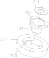
Taking the first embodiment as shown in fig. 1 to 12 as an example, the current interrupting device has a conductive member 201 and a flip member 202 connected to the conductive member 201 to be electrically connected to each other, and the flip member 202 and the conductive member 201 can be electrically disconnected under the action of air pressure, wherein in different embodiments of the present invention, the electrical connection can be disconnected in different ways, wherein the connection point between the conductive member and the flip member can be disconnected, for example, by pulling off a solder joint between the conductive member and the flip member to disconnect the electrical connection, or at least one of the conductive member and the flip member can be disconnected by itself, for example, by machining a weak notch on a corresponding component to disconnect the structure of the corresponding component, thereby disconnecting the electrical connection. That is, the present invention is intended to cut off the transmission of current by opening the mechanical structure under the action of air pressure.
Thus, taking the first embodiment as an example, when the battery is overcharged, gas is generated inside the battery and the gas pressure rises, at this time, under the action of a certain gas pressure, the turning member 202 is electrically disconnected from the conductive member 201 through the turning action, so that the circuit between the electrode terminal 101 and the outside is interrupted, the charging of the battery is stopped, the gas pressure inside the battery is prevented from continuing to rise, and the safety of the battery is ensured.
In the present exemplary embodiment, the electrode terminal 101 comprises a pole post 104 which is electrically connected to the cell, for example by means of an inner lead-through, wherein the pole post 104 passes through the cover plate 102 in order to lead the current out of the housing. In the present embodiment, the current interrupt device 200 may be mounted on the pole 104. This allows the air pressure inside the battery to be directly sensed through the pole 104, and thus, the battery has high sensitivity, and the separate connection of the current interrupt device 200 to the electrode terminal can be avoided, thereby facilitating the processing.
In the field of power batteries, for example, the current to be passed through is large, so that the welding structure of the conductive component 201 and the turnover component 202 needs to be stable, and the welding structure is prevented from being fused by a large current. Thus, in the present embodiment, as shown in fig. 5 and 6, the flip member 202 is connected to the conductive member 201 by a boss welding structure including a boss 203, a connection hole 204 receiving the boss 203, and an annular welding point 217 between the boss 203 and the connection hole 204. Namely, one of the boss 203 and the connecting hole 204 is located on the flip member 202, and the other is located on the conductive member 201. Therefore, it is ensured that the annular welding point 217 can stably weld the boss 203 accommodated in the connection hole 204 firmly, and the flow area of current can be increased to ensure the passage of large current. Specifically, as an example, the boss 203 may be formed on the conductive member 201, the connection hole 204 may be formed on the flip member 202, and more specifically, the flip member 202 is formed in a first sheet structure on which the connection hole 204 is formed, and the conductive member 201 is formed in a second sheet structure on which the boss 203 is formed. In other embodiments, the two may be interchanged. In addition, in some modes, the flip part 202 and the conductive part 201 can be welded by laser penetration welding or the like.
In this embodiment, the electrical disconnection between the turning member and the conductive member may be achieved by a notch, i.e., a weak portion with strength lower than that of other regions is machined at the corresponding portion, wherein the notch is usually an annular structure surrounding the connection point of the conductive member and the turning member, such as the boss welding structure described above, in order to complete the complete disconnection of the conductive member and the turning member. The breaking of the electrical connection is thus achieved by the breaking of the conductive member or the flip member itself, wherein the scores may be formed on the flip member or on the conductive member, in this embodiment the conductive member 201 is formed with a score 205, which score 205 surrounds the connection point for connecting the flip member 202, i.e. the conductive member 201 is provided with an annular score around the boss 203. Thus, when the internal air pressure of the battery rises, the air pressure can cause the score 205 to be pulled apart, so that the part of the conductive member 203 surrounded by the score 205 can be separated from the conductive member 201 along with the turnover member 202, thereby realizing the disconnection of the current. In other embodiments, the score may also be formed on the flipper 202.
As shown in fig. 7, in order to facilitate the snapping of the score 205, preferably, the score 205 may have an elliptical shape. This increases the sensitivity of score 205 to snapping by allowing the area of greater curvature to be stressed more intensively due to the different curvatures of the profiles when subjected to air pressure, which can be torn open first. Further, in the present embodiment, the boss 203 is circular, and the center of the ellipse of the score 205 and the center of the boss 203 are offset in the major axis direction of the ellipse. Thus, the stress in the areas at the two ends of the major axis of the ellipse is uneven, so that the notch 205 is broken from a local point conveniently, and the sensitivity of the notch 205 is improved.
In addition, a conductive member turnover member 202 may be provided coaxially with the electrode terminal 101, and a conductive member 203 may be provided obliquely with respect to the axis of the electrode terminal 101. This may allow the lower score to snap first, thereby increasing the sensitivity of score 205 to snap. Further, when the notch 205 is oval, the major axis of the oval may be inclined to the axis of the conductive member, and when the conductive member is mounted on the pole 104, the major axis of the oval may also be inclined to the axis of the pole. Thereby facilitating the tearing of the area of greater curvature of the end of the major axis first, thereby ensuring that the nick 205 can be broken normally when needed, ensuring the normal operation of the current interrupt device 200.
In addition, in order to further ensure that the score 205 is pulled apart, as shown in fig. 7, a weakening hole 206 may be formed in the score 205. So that the scores 205 are easily broken from the weakening holes 206, wherein the size and the number of the weakening holes 206 can be set according to actual conditions. Preferably, the weakening holes 206 are plural and are provided at intervals along the scores 205. In addition to the weakening function, when the scores are designed on the conductive member 201, the weakening hole 206 may also function as an air guide so that the gas inside the battery can act on the flip member 202 through the weakening hole 206.
When the current interrupt device 200 is installed on the pole post 104, the conductive member 201 is connected to the outer end surface of the pole post 104, and the outer periphery of the flip member 202 is fixed relative to the cover plate 102. Thus, the scores 205 formed on the conductive member 201 can be broken by the air pressure with the outer peripheral edge of the flip member 202 as a supporting point. Additionally, to allow the flipper 202 to be subjected to air pressure, the outer periphery of the flipper can be sealed, such as by welding, to the cover, so that the internal air pressure can force the flipper to snap the score 205. Wherein here and in the similar description the outer end, the inner end are defined in relation to the housing in the axial direction of the pole, and "inner, outer" in relation to the ring-shaped element, such as the outer circumference, is defined in the radial direction in relation to the centre of the ring-shaped element.
In order to ensure that the conductive component 201 is fixed to the pole post 104, the score 205 thereon can also be broken, preferably, a receiving hole 218 is formed on an outer end surface of the pole post 104, and an outer peripheral edge of the conductive component 201 is fixed on an inner wall of the receiving hole. In this way, the conductive member 201 can be stably fixed by the annular periphery, and the region inside the score 205 is not connected with the pole 104 and can be pulled apart by an external force, such as the pulling force of the turnover member 202 or the direct pressure of gas.
In the present invention, the current interrupt device 200 is in gas communication with the inside of the battery in various ways, and in this embodiment, the pole post 104 is formed with an air guide hole communicating the inside of the case and the current interrupt device 200. Thus, air pressure is applied to the current interrupt device directly through the internal structure of the pole 104. The structure is simpler.
In the present embodiment, the air guide hole includes two air guide holes 103, wherein the first air guide hole 103 is used for communicating the accommodating hole 218 with the inside of the housing, that is, the first air guide hole 103 directly presses the conductive member 201 to break the score 205. That is, the air guide hole passage includes the air guide hole 103 for communicating the receiving hole 218 and the inside of the casing. The second type of vent 103 is used to communicate the flip member 202 with the interior of the housing, thereby applying pressure to the flip member to snap score 205. Wherein, in order to improve the force efficiency of the turnover part 202, the air guide hole 103 may be a plurality of holes surrounding the receiving hole. Therefore, the sensitivity of the current interrupt device can be increased by the combined action of the two kinds of air-guide holes 103.
Specifically, as shown in fig. 2 and 8, the electrode post 104 is fixedly connected to the cover plate 102, so that the electrode terminal structure is stable. Wherein, the outer end periphery of the pole 104 has a radial boss 105, the radial boss 105 is fixedly connected to the cover plate 102, and a second gas guide hole 103 can be machined on the radial boss 105 to allow the gas to flow to the turnover part 202. In the present embodiment, the first air hole 103 is formed in the pole 104 in the circumferential direction. That is, the air holes 103 on the radial bosses 105 are used for pressing the turning member 202, and the air holes 103 below the receiving hole 218 can directly press the conductive member 201. As shown in fig. 9, the radial bosses 105 and the body of the pole 104 in the embodiment of the present invention are formed with air holes 103, wherein the first type of air holes 103 on the body are communicated with the accommodating holes 218 on the end surface, and the number of the air holes is four and is arranged at equal intervals along the circumferential direction. In other embodiments, the number of the first air holes 103 may be other numbers, which is not limited in the present invention.
As shown in fig. 2, 3, 8 and 10, in order to avoid the cover plate from being charged, it is preferable that the post 104 is insulated from the cover plate while the cover plate is fixedly connected, and therefore, the post 104 is fixedly connected to a ceramic ring 207 hermetically connected to the cover plate 102, for example, by ceramic brazing. Like this, compare the insulation that plastics, rubber etc. realized, reliability and weatherability are stronger, not only can realize current interrupt device's firm sealing connection, can also realize the two insulation. Specifically, the outer end periphery of the pole post 104 has a radial boss 105, and the inner edge of the ceramic ring 207 has a radial support 208 connected to the radial boss 105, wherein the radial boss 105 can be embedded in the ceramic ring 207 and connected to the radial support 208, i.e. the thickness of the radial support 208 is thinner to form a stepped receiving space for embedding the pole post 104.
As shown in fig. 11, in another embodiment of the present invention, different from the above-mentioned ventilation method by forming the air holes 103 on the pole, the radial bosses 105 and the radial supports 208 are respectively provided in a plurality at intervals in the circumferential direction, that is, the radial bosses 105 are provided in a plurality at intervals in the circumferential direction, the radial supports 208 are also provided in a plurality at intervals in the circumferential direction, and the plurality of radial bosses and the plurality of radial supports correspond to each other one by one. Like this, can realize ventilating through the interval between the adjacent radial boss 105 and between the radial support 208, the structure is simple more ingenious, and processing is convenient, need not additionally to set up the air duct on utmost point post 104 to can not influence the regional of the electrically conductive piece 201 of utmost point post 104 assembly, can maximize the size of electrically conductive piece 201, thereby increase the nick size and guarantee the sensitivity of breaking. In this embodiment, the radial bosses 104 are three arranged at equal intervals to give consideration to the connection stability and the air permeability. In other embodiments, the number of radial bosses may be other, such as four or more.
In both embodiments, the outer end face of the ceramic ring 207 is formed in a stepped structure having an inner ring and an outer ring, and the pole 104 is embedded and connected to the inner ring. The difference is that in the embodiment of the integral radial boss 105, the inner ring forms an integral annular radial support, while in the embodiment of the split radial boss, the inner ring forms the plurality of radial supports 208 arranged at intervals, so that the integral structure is more compact and the connection is more stable.
In the present embodiment, in order to establish a current flow path with the outside, it is preferable that an electrically conductive ring 216 is hermetically connected to the outer end surface of the ceramic ring 207, specifically, to the outer ring, and the outer periphery of the turning member 202 is fixedly connected to the electrically conductive ring 216, that is, the turning member 202 is connected to the ceramic ring 207 through the electrically conductive ring, and the electrically conductive ring can establish a current loop with the outside. Wherein, the conductive ring is still electrically connected with the pole post after the nick is broken, and the effect of current interruption is lost. Preferably, the conductive ring 216 is sealingly connected to the outer ring of the ceramic ring to be insulated from the pole, i.e. the pole 104 and the conductive ring 216 are insulated by the ceramic ring. In addition, the sealing connection of the conductive ring 216 to the ceramic ring allows the outer periphery of the flip to be sealed, thereby allowing the air pressure inside the enclosure to act on the flip without leaking air.
The conductive ring 216 has an L-shaped slot formed on an outer end surface thereof for stably connecting the conductive ring and the flip member, and an inner end surface thereof for connecting an outer ring of the ceramic ring, the flip member 202 has an outer peripheral edge embedded and supported in the L-shaped slot, and the outer peripheral edge is hermetically connected to the L-shaped slot through a cap 210 covering the flip member 202, so that the current interrupt device 200 can be protected while stably and hermetically assembling the flip member 202, and the conductive ring 216 can establish a current loop with the outside through an electrode lead-out piece connected to the cap or directly connected to the cap, for example, between the adjacent unit cells 100, or between the adjacent battery modules through the electrode lead-out piece.
To facilitate the sealing connection of the ceramic ring 207 to the cover plate 102, preferably, a transition ring 209 is sealingly connected to an inner end surface of the ceramic ring 207, the transition ring 209 may be connected to the ceramic ring 207 by ceramic brazing, and the transition ring 209 is sealingly connected to the cover plate 102. Wherein the transition ring 209 may also space the ceramic ring 207 from the cover plate 102. Because the ceramic ring 207 is not directly assembled with the cover plate 102, the high temperature of the cover plate 102 during the brazing of the ceramic ring is avoided, in addition, the limitation on the area of the ceramic ring 207 due to the direct assembly with the cover plate 102 is avoided, in addition, the special design of the ceramic ring 207 is not needed, and the manufacture and the assembly are convenient.
As shown in fig. 8, preferably, the transition ring 209 has an inner ring and an outer ring forming a Z-shaped structure, the cover plate 102 is formed with a through hole for the pole 104 to pass through, an end face of the through hole is a stepped structure, and the inner ring of the transition ring is embedded and supported in the stepped structure. That is, in fig. 8, the inner ring is positioned below and inserted into the through hole, so that the contact area between the inner ring and the through hole is increased to ensure stable connection.
Therefore, in the present embodiment, in order to achieve the operation of the current interruptive device, the outer periphery of the flip 202 needs to be sealed, and particularly, a ceramic ring 207 is sealingly connected between the outer periphery of the flip and the cover plate, so that the stable and reliable operation of the current interruptive device is achieved by the sealing of the ceramic structure. In the ceramic sealing structure, the air pressure inside the shell can effectively act on the current interruption device through respective sealing between the cover plate and the transition ring, between the transition ring and the ceramic ring, between the ceramic ring and the conducting ring, and between the conducting ring and the turnover part, so that the current interruption device works reliably. In order to ensure the tightness of the current interrupt device during assembly, the ceramic ring 207 is hermetically connected to the conductive ring 216, the pole post 104 and the transition ring 209 by ceramic brazing. These four components can be first assembled into a separate assembly and then assembled to the cover plate 102 by laser welding the transition ring 209 thereto, which is convenient to assemble without directly brazing the ceramic to the cover plate. In addition, the conductive member 201 and the post 104 may be connected by laser welding, the flip member and the conductive member may be connected by laser penetration welding or by welding such as the above-mentioned projection welding structure, and the cap 210 may be connected to the conductive ring by laser welding. In addition, the pole post 104 may be laser welded to the lead-out piece of the cell, thereby completing assembly and operation of the overall current interrupt device.
The above mainly describes the structure of the current interrupt device in the first embodiment, and the arrangement of the current interrupt device in the first embodiment will be described below.
In order to ensure the normal and timely operation of the above-described air pressure-driven current interrupt device, the current interrupt device may be designed to be large in size, so that the breaking force is increased by increasing the force-receiving area in the case where the air pressure is not changed. For example, the area of the flipper is designed to be large to increase the pull off force of the flipper. In the present embodiment, as shown in fig. 1, the current interruptive device 200 is designed to extend radially out of the cover plate 102, thereby increasing the size. In this case, in the battery module, the number of the unit batteries 100 is plural, and in order to prevent the extended current interruptive device 100 from interfering with the electrode terminals of the adjacent unit batteries 100, it is preferable that the current interruptive device 200 is offset from the adjacent electrode terminals in the height direction and/or the extending direction of the cover plate. Thus, the area of the cover plate 102 without the electrode terminal 101 can be fully utilized, so that the projected current interruption device cannot interfere with the structure of the adjacent cover plate, the space in the battery pack is fully saved, and the energy density in the pack body is improved. It should be noted that, in the present invention and in the following description, the meaning of the current interruptive device and the adjacent electrode terminal, or the meaning of the electrode terminal and the adjacent electrode terminal, between the adjacent single cells, refers to the connection of adjacent features between different single cells, rather than the connection of adjacent features on the same single cell.
In the present embodiment, the current interrupt device 200 and the adjacent electrode terminal 101 are shifted from each other in the extending direction of the lid plate. In other embodiments, the two may also be offset from each other in the height direction.
As an example, as shown in fig. 1, between the adjacent unit batteries 100, the current interruptive device 200 is connected with the adjacent electrode terminal by an L type connector 214, the L type connector 214 has a covering part 211 and a leading part 212, the covering part 211 is covered and connected on the current interruptive device 200, the leading part 212 extends to the adjacent electrode terminal to be adjacent to it, wherein, the L type inflected structure as described in fig. 1 may first extend to be aligned with the adjacent electrode terminal in the extending direction of the cover plate and then extend to the electrode terminal, in other embodiments, the L type connector may first extend to the adjacent cover plate and then extend to the electrode terminal, thereby achieving the electrical connection between the two.
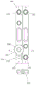
As another example, as shown in fig. 2, between the adjacent unit batteries 100, the current interruptive device 200 includes a cap 210 covering the flip member 202, the cap 210 extending along the cap plate 102 to be aligned with the adjacent electrode terminals, i.e., having a cover portion 211 and a lead portion 212 arranged in a straight line, and being connected to the adjacent electrode terminals by straight type I-shaped connectors 215. The I-type connector 215 may also be used to connect electrode terminals 101 of other unit batteries 100 without the current interruptive device 200, so that the use of such a connector within the overall battery module is basically only required by the shape of the cap 210.
Unlike the above-described embodiment shown in fig. 2, a larger current interruption device may also be adapted by adding the unit battery 100, as shown in fig. 12. Specifically, between adjacent unit batteries 100, the width of the unit battery 100 provided with the current interruptive device 200 is greater than the width of the unit battery not provided with the current interruptive device 200, and the current interruptive device 200 extends close to the width edge of the cap plate 102, so that the fitting of the current interruptive device 200 can be achieved as well.
In addition, since the width of the corresponding unit cell is large, the current interruptive device may not protrude from the cap plate, and thus adjacent electrode terminals may be aligned with each other. This also prevents the current interruptive device 200 extending out of the cover plate 102 from affecting other structures such as the welded structure on the attached cover plate 102. And preferably, the current interruptive device and the adjacent electrode terminal may be connected by a straight type I-shaped connecting member 215.
In addition, when the single battery 100 is used, although the width of the single battery 100 is increased, the cell capacity is not increased, that is, the cell capacity of the single battery 100 provided with the current interrupt device 200 is the same as the cell capacity of the single battery 100 not provided with the current interrupt device, so that the single batteries with different capacities under the same module are avoided, and the influence on the BMS is avoided. The battery cells have the same capacity, and the excess size inside the shell can be filled by adopting the partition plates, namely, the partition plates are filled around the battery cells. So that the assembling structure of the battery cell is stable. Wherein the size of the battery module and the size of the monomer are considered comprehensively, and the volume ratio of the battery core to the partition board can be 1: 1-2: 1, wherein the separator may be made of an electrolyte-resistant material.
In addition, in view of the current interruption effect, cost, and assembly, the number of the unit batteries in which the current interruption device 200 is provided does not exceed three in the plurality of unit batteries 100 of the same module; preferably, the number of the unit batteries of the current interruptive device 200 is set to 3; preferably, the unit cells provided with the current interruptive device 200 are unit cells located at the end portions and the central portion of the battery module; if the battery module comprises n single batteries which are sequentially arranged, the single batteries at the end part of the battery module are the 1 st single battery of the battery module and the nth single battery of the battery module; when n is an odd number, the single battery at the central part of the battery module is the (n + 1/2) th single battery of the battery module; when n is an even number, the single battery at the central part of the battery module is the (n/2) th single battery or the (n + 2/2) th single battery of the battery module, wherein n is more than or equal to 3.
The current interrupt device, the single battery, and the battery module according to the first embodiment of the present invention are described above, and features of the first embodiment, such as the boss welding structure, the oval notch, the ceramic ring, etc., may be applied to other embodiments described below without departing from the spirit of the present invention, and a power battery according to a second embodiment of the present invention will be described below with reference to fig. 13 to 17.
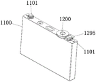
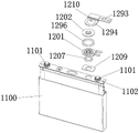
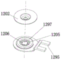
As shown in fig. 13 and 14, a second embodiment of the present invention provides a unit battery 1100, the unit battery 1100 including a case, a cell accommodated in the case, an electrode terminal 1101 electrically connected to the cell, and a cover plate 1102 enclosing the case, the electrode terminal 1101 being provided on the cover plate 1102 for input and output of current. Wherein the single cell 1100 further includes a current interruptive device 1200 in gaseous communication with the interior of the case, in a manner different from the manner of mounting on the electrode terminal in the first embodiment, the current interruptive device 1200 is disposed on the cover plate and in gaseous communication with the interior of the case, wherein the current interruptive device 1200 has a conductive member 1201 and an upset member 1202 connected to the conductive member 1201 to be electrically connected to each other, the upset member 1202 and the conductive member 1201 being capable of being electrically disconnected under the action of gas pressure. That is, the current interrupt device 1200 basically has the same operation principle as the current interrupt device of the first embodiment, and turns over the inverter by sensing the gas pressure in the cell to turn off the circuit.
Among them, since the conductive member 1201 has the body portion 1299 connected to the flip 1202 and the connecting portion 1298 extending from the body portion 1299 to the electrode terminal 1101 and connected to the electrode terminal 1101, instead of being provided on the electrode terminal, by providing the current interruptive device 1200 on the cap plate in the second embodiment, it is possible to avoid heightening the electrode terminal 1101, thereby increasing the capacity density of the battery by using the length space of the cap plate.
As shown in fig. 15-17, in this embodiment, the body portion 1299 of the conductive member 1201 is in gaseous communication with the interior of the housing and is formed with a score 1205, the score 1205 being disposed around the connection point for connecting the flip member 1202. So that the scores can be broken by the internal air pressure to break the electrical connection between the flip member and the conductive member. Further, a vent 1206 is provided on the notch 1205. Like this, not only can make atmospheric pressure can act on upset piece 1202 through the air vent 1206, and through the actual pulling force of upset piece to the nick, can conveniently break casing 1205 at the position of this air vent 1206 moreover, play the effect of the sensitivity of promotion upset piece 1202, the nick also can set up on the upset piece this moment. Wherein the vent 1206 can be multiple and spaced along the score 1205. Further, as for the characteristics such as scores and vents, the characteristics of the first embodiment can be applied to the present embodiment. In other embodiments, the body portion of the conductive member and the flip member may be provided with scores, respectively. Like this, when the inside atmospheric pressure of shell constantly rises, except that the nick on breaking electrically conductive piece comes the interrupt current, can also continue to break the nick on the upset piece, the inside gas of battery can fill upset piece department and outwards let out this moment, and avoids the atmospheric pressure in the shell of battery cell to continue to increase and guarantee. In addition, a gas sensor in the battery pack can sense an alarm or cut off the circuit. This section will be described in detail later.
Specifically, the score 1205 on the body portion can snap under a first air pressure within the enclosure, the score on the flipper can snap under a second air pressure within the enclosure, and the second air pressure is greater than the first air pressure. I.e. the first score is less strong than the second score to enable it to be broken by the smaller first air pressure. The second notch is continuously broken to release the pressure only when the air pressure is continuously increased.
In this embodiment, in order to ensure that the turning piece 1202 can receive the internal air pressure force, the outer periphery of the turning piece 1202 is hermetically connected with the conductive piece 1201 to prevent the air from being released from the outer periphery of the turning piece. Specifically, the cover plate 1102 is provided with a vent hole in gas communication with the inside of the housing, the cover plate is hermetically connected with a first ceramic ring 1207 surrounding the vent hole, and the body portion 1299 is hermetically connected to the first ceramic ring 1207, so that the internal gas pressure can act on the body portion 1299 without leakage. Also to stabilize the assembly of the flipper 1202, the outer periphery of the flipper 1202 is sealingly attached to a second ceramic ring 1296, which is sealingly attached to the conductive member 1201. Therefore, due to the insulating property of the second ceramic ring, the outer periphery of the flip part 1202 can be stably supported, and the conductive member and the outer periphery of the flip part 1202 can be insulated by the second ceramic ring 1296, so that the current connection can be kept disconnected after the flip part 1202 and the conductive member 1201 are broken by the notch 1205, thereby playing a role of current interruption.
Specifically, as shown in fig. 17, the body portion 1299 of the conductive member 1201 is formed with an annular projection 1297 surrounding the notch 1205, such that the inner radial side of the annular projection 1297 may be configured to form the notch 1205, and such that the backside recess of the annular projection 1297 may sealingly receive the first ceramic ring 1207, and the outer side of the annular projection 1297 may be configured to sealingly support the second ceramic ring 1296. Thus, the unique structure of the conductive member as illustrated in fig. 16 in the second embodiment of the present invention enables more convenient installation of the current interruptive device 1200.
In addition, the first ceramic ring 1207 is sealingly attached to the cover plate 1102 by a transition ring 1209, as shown in FIG. 17, the transition ring 1209 having a connecting body embedded in the inner wall of the vent and a flange ring for connecting the first ceramic ring 1207. The flange ring projects radially from the connecting body and engages the cover plate. Thereby ensuring a stable mounting of the current interrupt device 200 without the first ceramic ring 1207 being directly connected to the cover plate 1102.
In the present embodiment, for convenience of connection, it is preferable that the electrode terminal 1101 includes a pole 1104 passing through the cap plate 1102 and electrically connected to the battery cell, the connection portion 1298 of the conductive member 1201 is formed with a slot 1295, and the pole 1104 penetrates into the slot 1295 and is welded to each other, thereby achieving stable connection therebetween, in addition, the current interruptive device 1200 includes a connecting member 1210 covering the flip member 1202 and electrically connected to the flip member 1202, the connecting member 1210 has a covering portion 1294 covering the flip member 1202 and a lead-out portion 1293 extending from the covering portion 1294, wherein the connecting member 1210 may be formed in the same structure as the L type connecting member 214 of the first embodiment, i.e., the covering portion and the lead-out portion are formed in a L type inflection structure, thereby facilitating the lead-out of the current interruptive device 1200 to an adjacent electrode terminal or module.
In the battery module in which at least one unit cell is the unit cell 1100, the current interrupt device radially extends out of the cap plate, thereby increasing a force-receiving area and increasing a breaking force. Between the adjacent unit cells, the current interruptive device and the adjacent electrode terminal are offset from each other in the extending direction of the cap plate 1102, thereby avoiding interference with the structure on the adjacent cap plate. Also, as in the first embodiment, the number of the unit batteries 1100 provided with the current interruptive device 1200 is not more than three.
In the power battery provided by the second embodiment of the present invention, the features different from those of the first embodiment are mainly described, and the features of the two embodiments can be replaced and combined without contradiction, which will not be described in detail herein.
A battery cell 2100 according to a third embodiment of the present invention will be described with reference to fig. 18, which includes a housing, a cell accommodated in the housing, an electrode terminal 2101 electrically connected to the cell, and a cover 2102 enclosing the housing, the electrode terminal 2101 being disposed on the cover 2102, wherein the battery cell includes a first electrode lead-out 2298 electrically connected to the cell, and a second electrode lead-out 2297 electrically connected to the electrode terminal 2101, the cover 2102 further being provided with an explosion-proof valve 2200 in gas communication with the interior of the housing, the explosion-proof valve 2200 having a flip 2202 connecting the first electrode lead-out 2298 and the second electrode lead-out 2297, that is, the two electrode leads are connected via the flip 2202.
The first nick 2205 is formed on the first electrode lead-out piece 2298 and/or the second electrode lead-out piece 2297, and the first nick 2205 can be broken under the action of air pressure in the casing to interrupt current on the first electrode lead-out piece 2298 and/or the second electrode lead-out piece 2297, that is, the first nick is used for breaking the electrode lead-out piece provided with the first nick to interrupt the transmission of current, so that the electrical connection between the battery core and the electrode terminal can be broken by arranging the first nick on at least one of the two electrode lead-out pieces, and the transmission of current between the battery cell and the outside is then broken. In addition, the turning piece 2202 is further provided with a second notch 2299, the second notch 2299 can be cut off under the action of the air pressure in the shell, so that the air in the shell is leaked out through the turning piece 2202, namely, the second notch is used for ventilation, and the internal air can be leaked out after the second notch is cut off, so that the situation that the internal air pressure of the battery is continuously increased to cause explosion is avoided, and an explosion-proof effect is achieved.
Specifically, the first score is capable of snapping under a first air pressure within the housing, the second score is capable of snapping under a second air pressure within the housing, and the second air pressure is greater than the first air pressure. That is, the strength of the first score 2205 is less than that of the second score 2205 to enable the first score to be broken by the smaller first air pressure. The second score 2205 is broken to release pressure only when the air pressure continues to rise.
As shown in fig. 18, in the present embodiment, the two electrode lead-out members may be of a long sheet structure, so that in order to be able to break the current, the first score 225 extends from one side edge to the other side edge in the width direction of the long sheet structure, which may make it possible to break the long sheet structure along the first score more timely. Wherein the turning part 2202 may be formed with an annular outer wall, and the two electrode lead-out parts may be fixedly connected to the annular outer wall to realize current transfer. Specifically, in the present invention, the annular outer wall of the flip may be formed by, for example, a boss in a boss welding structure, and the flip is further formed with a cone ring structure extending obliquely outward from the boss to the outer peripheral edge of the flip to form the flip in a bowl shape. In addition, the second nick can form into the ring structure around the circumference of upset piece to thoroughly break off under the atmospheric pressure effect, increase gas pressure release efficiency. In particular, the second score may be formed on the cone ring structure. In order to ensure that the turnover part can be effectively broken by the air pressure to break the first score and the second score, the outer periphery of the turnover part 2202 is in relatively fixed insulation seal with the cover plate, so that on one hand, the phenomenon that the air leaks to cause the two scores to lose effect under the condition that the first score and the second score are not broken can be avoided. On the other hand, the cover plate can be prevented from being electrified through the insulation connection.
In this embodiment, the electrode terminal 2101 includes a pole penetrating through the cover plate, which is insulated from the outside of the cover plate by a second ceramic ring so as to establish a current loop with the outside. That is, the adjacent unit cells are connected to each other through the electrode terminals. Wherein the cover plate can be prevented from being electrically charged by the ceramic ring. In addition, a first ceramic ring 2207 is hermetically connected between the outer periphery of the turning member 2202 and the cover plate, and also plays a role in sealing and insulating.
In addition, in order to facilitate the connection of the turning member 2202, a first transition piece 2295 is fixedly connected to the cover plate 2102, a second transition piece 2296 is fixedly connected to the periphery of the turning member 2202, and the first transition piece and the second transition piece may be aluminum sheets. The first and second transition pieces 2295 and 2296 are brazed coaxially with the first ceramic ring 2207. Thus, when assembling, the two transition pieces can be firstly welded to the ceramic ring in a brazing mode, and then the two fixing pieces are welded to other structures, so that high temperature and the like caused by brazing between the ceramic ring and the cover plate and other structures can be avoided, assembling is convenient, sealing, stabilizing and insulating sealing is realized through the first ceramic ring 2207, and the cover plate 2102 can be prevented from being electrified.
Specifically, first transition piece 2295 and second transition piece 2296 may each be an annular structure to accommodate two annular end faces of the ceramic ring. Further, preferably, the cover plate 2102 is formed with an annular boss on which the first transition piece 2205 is supported, and the ceramic ring extends against an inner wall of the annular boss toward the second transition piece 2296, thereby stably attaching the ceramic ring within the cover plate 2102.
In addition, the explosion-proof valve also comprises a protective membrane 2099, which can be broken by the gas pressure, which covers the flip-flop 2202 in a sealed manner, in particular is connected to the first transition piece 2295 remote from the flip-flop. Thus, the protective film 2099 can protect the interior of the explosion-proof valve 2200 under normal conditions, and can be burst by a certain pressure, such as a second pressure, when explosion protection is required, so as to avoid affecting the explosion-proof effect of the explosion-proof valve.
In addition, in order to realize the sequential stretch breaking of the two scores, the ratio of the residual thickness of the first score to the residual thickness of the second score is 1:3-1: 1.2. Further 1:2-1: 1.3.
The above description has been made of the unit cell provided by the third embodiment of the present invention. A fourth embodiment of the present invention will be described with reference to fig. 22.
A fourth embodiment of the invention provides a battery cell 3100 and a battery module using the same. The battery cell 3100 includes a housing, a battery cell accommodated in the housing, a cover plate 3102 encapsulating the housing, and an electrode terminal 3101 disposed on the cover plate 3102, wherein the battery cell 3100 further includes an inner lead member 3299 electrically connected to the battery cell, and a current interrupt device 3200 connected between the inner lead member 3299 and the electrode terminal 3101, wherein, unlike the first embodiment which is mounted on the outer end of the battery post, the current interrupt device 3200 of the present embodiment is located inside the cover plate 3102 and is in gas communication with the inside of the housing so as to be able to interrupt a flowing current by gas pressure, and wherein an adaptor 3298 extending radially outward from the outer peripheral edge is connected to the electrode terminal 3101 so as to be connected to the outer peripheral edge of the current interrupt device via the adaptor 3298.
Like this, owing to have the adaptor 3298 of radially extending outward from the outer peripheral edge of electrode terminal for the current interruption device who links to each other with the adaptor 3298 radial outside compares the mode that directly links to each other with electrode terminal, and its area can be designed bigger, thereby increase the application of force area of inside atmospheric pressure to electrode interruption device, thereby can promote electrode interruption device's atress under the unchangeable circumstances of atmospheric pressure, and promote current interruption device 3200's sensitivity, in time accomplish the cutting off of electric current. Particularly, in the field of application of the battery of the present invention to a large battery such as a power battery, since a large current is often required to be transmitted, the transmission of a large current is utilized by increasing the number of the adapters and increasing the size of the current interrupting device.
In the present embodiment, the adaptor 3298 is formed in a ring structure, an inner circumference of the ring structure is connected to an outer circumference of the electrode terminal, and an outer circumference of the ring structure is connected to an outer circumference of the current interruptive device, thereby playing a role of increasing an area of the current interruptive device.
In the present embodiment, in order to increase the firmness of the adaptor and the electrode terminal and the current interrupt device, the stability of current transmission is ensured. Preferably, the inner circumference of the ring structure is matched with the outer circumference seam allowance at the inner end of the electrode terminal, specifically, the seam allowance can be formed on the outer circumference of the inner end of the electrode terminal, and the inner circumference of the adaptor is embedded into the seam allowance and connected, so that the connection area is increased, the connection stability is ensured, and the current transmission efficiency can be increased. Wherein the inner and outer ends of the electrode terminal are defined with respect to the housing in the axial direction thereof, i.e., proximate to the interior of the housing are inner ends.
In addition, in the present embodiment, the outer peripheral edge of the ring-shaped structure protrudes inward of the case, i.e., the ring-shaped structure itself is formed in a structure of a ring cap, and the current interruptive device is fitted with the inner seam allowance of the outer peripheral edge, thereby not only ensuring stable connection and increasing current transfer efficiency but also being capable of separating the current interruptive device and the electrode terminal, thereby making a space for the current interruptive device to be disconnected under the action of air pressure.
In this embodiment, the inner lead 3299 includes a tab (not shown) connected to the cell, the tab extending from the cell toward the cover. The inner lead-out member further comprises a support slot for accommodating the current interrupt device, and a connecting plate extending from the support slot in the opposite direction, the connecting plate being in insulated connection with the cover plate, respectively, to avoid charging of the cover plate, in particular, the connecting plate may be formed as an integral sheet structure with the connecting slot, i.e. the connecting slot comprises two side walls and a bottom wall, the two side walls being connected with the connecting plates on both sides, respectively. In addition, in order to make the current interrupt device in gas communication with the inside of the housing, it may be designed that a gas passing hole in gas communication with the inside of the housing is formed on the bottom wall of the support groove.
In this embodiment, the inner lead 3299 is connected to the inner side of the cover 3102 through a ceramic material 3296 in an insulating manner in order to prevent the cover from being charged. Specifically, the ceramic piece 3296 may be formed as a ceramic piece and is welded to the inner lead piece 3299 and the cover plate through the transition piece 3294, that is, the transition piece 3294 is two pieces, which may be aluminum pieces, and is respectively located on the upper surface and the lower surface of the ceramic piece 3296, the ceramic piece 3296 is welded to the cover plate 3102 through the transition piece 3294 located on the upper surface of the ceramic piece 3296, and the ceramic piece 3296 is also welded to the inner lead piece 3299 through the transition piece 3294 located on the lower surface of the ceramic piece 3296, so that the welded connection between the ceramic piece 3296 and the cover plate 3102 and the inner lead piece 3299 is easier to achieve, and the welded structure is stable. The ceramic member 3296 and the transition piece 3294 positioned on the upper and lower surfaces thereof may be connected by ceramic brazing, the transition piece 3294 positioned on the upper surface of the ceramic member 3296 and the cover plate 3102 may be connected by laser welding, and the transition piece 3294 positioned on the lower surface of the ceramic member 3296 and the inner lead member 3299 may be connected by laser welding.
In the present embodiment, the current interruptive device 3200 has a conductive member 3201 and a flip member 3202 connected to the conductive member 3201 to be electrically connected to each other, and the flip member 3202 and the conductive member 3201 can be electrically disconnected by gas pressure, wherein the conductive member 3201 is connected to the inner lead member 3299 and is formed with a gas guide hole 3203 in gas communication with the inside of the case, and specifically, the conductive member 3201 is embedded in a support groove connected to the inner lead member such that a gas through hole formed in the support groove can be in gas communication with the gas guide hole 3203, so that the flip member 3202 can feel the pressure of the inside gas of the case to electrically disconnect the flip member 3202 and the conductive member 3201 by the internal gas pressure. Wherein an outer periphery of the flip 3202 is connected with an outer periphery of the adaptor 3298 to establish a current connection path.
In this embodiment, as a way of breaking the electrical connection, the conductive member 3201 is formed with a notch, which is disposed around a connection point for connecting the flip member 3202. Thus, under the action of the internal air pressure, the score will be pulled apart and break the electrical connection with the flipper. In other embodiments, the score may be formed on the flipper or by breaking the attachment point. In order to realize the pressing of the flip part 3202 by the air pressure, the outer circumference of the flip part 3202 is supportedly coupled to the conductive member 3201 and/or the inner lead part 3299 through the insulating member 3295, so that the assembly of the flip part 3202 is realized through the insulating member 3295, which can ensure the insulation of the outer circumference of the flip part from the inner lead part 3299 and the conductive member, thereby preventing the electrical connection between the outer circumference and the conductive member or the inner lead part after the electrical connection between the flip part and the conductive member is not disconnected by the air pressure.
Specifically, the insulating member may be an annular insulating member such as a ceramic ring, a sealing ring, etc., wherein the insulating member has three connection modes, the first is supported on the conductive member 3201 in a sealing manner, specifically, on a region of the conductive member 3201 surrounding the pulled-off region, the second is supported on the inner lead member 3299, specifically, on a region of the inner lead member 3299 surrounding the conductive member 3201, and the third is supported on both the inner lead member 3299 and the conductive member 3201, that is, as shown in fig. 23, the insulating member is supported on a connection region of the inner lead member 3299 and the conductive member 3201.
In order to ensure stable current transmission between the conductive member and the flip member, especially for a power battery with a large current, similar to the first embodiment, in the case that the conductive member is provided with the notch 3205, as shown in fig. 23, the flip member 3202 and the conductive member 3201 are connected by a boss welding structure surrounded by the notch 3205, the boss welding structure includes a boss 3203, a connection hole 3204 for accommodating the boss 3203, and an annular welding point 3217 between the boss 3203 and the connection hole 3204, thereby ensuring effective passage of the large current. Specifically, as shown in fig. 23, unlike fig. 6 of the first embodiment, a boss 3203 is formed on the flip member 3202, and a connection hole 3204 is formed on the conductive member 3201. Further, as in the first embodiment, a boss may be formed on the conductive member 3201 and the connection hole 3204 may be formed on the flip member.
In addition, as shown in fig. 22, as an example, the conductive device 3201 may be formed in a cap-like structure including a cap body coupled to the flip member and a visor surrounding the cap body, wherein the air guide hole is formed in the visor and coupled to the inner lead member, and the cap body protrudes toward the flip member, the flip member is formed in a sheet-like structure, and the insulating member 3295 is coupled between an outer circumference of the sheet-like structure and the visor. Therefore, the current interruption device provided by the invention has a compact structure and is stable to assemble.
In the present embodiment, in order to establish a current loop with the outside, it is preferable that the electrode terminal 3101 includes a pole column 3104 penetrating through the cover plate, which is insulated from the cover plate by a ceramic ring 3293 to prevent the cover plate from being electrified, and an adaptor 3298 is attached to an inner end of the pole column to establish a current loop with the outside through a portion exposed outside the cover plate. Specifically, the ceramic ring 3293 is sealingly attached to the outer surface of the cover plate and sealingly attached to the post 3104 to ensure a sealing effect inside the cover plate. Wherein, an air hole 3292 is formed on the pole column along the axial direction. In this way, the current interrupt device 3200 is not affected by the pressure of the sealed cavity in the cover plate during the process of the electrical connection interrupted by pressure, but a pressure difference can be established between the current interrupt device 3200 and the external atmosphere, so that the flip 3202 can act under the action of the pressure difference between the inside and the outside to break the notch 3205.
The above description has been made of the unit cell provided by the fourth embodiment of the present invention. A fifth embodiment of the present invention will be described with reference to fig. 24.
A fifth embodiment of the present invention provides a unit cell 4100 and a battery module using the same, wherein the unit cell 4100 includes a case, a cell accommodated in the case, an electrode terminal 4101 electrically connected to the cell, and a cover plate 4102 enclosing the case, the electrode terminal 4101 is disposed on the cover plate 4102, wherein the electrode terminal includes a post 4104 penetrating the cover plate 4102 and electrically connected to the cell through an internal lead 4196, the unit cell further includes a current interrupt device 4200 mounted on the post 4104, the current interrupt device 4200 has an inverse 4202 fixed to the cover plate 4102 and in gas communication with the inside of the case, and the inverse 4202 is connected to an outer end surface of the post 4104 through a connection point, which can be disconnected under air pressure. Thus, the current interrupt device of the present embodiment operates on the principle that the connection point of the flip 4202 and the pole 4104 is directly pulled by the air pressure, thereby interrupting the electrical connection therebetween.
To improve sensitivity, the flip 4202 is preferably connected to the post by a single weld 4199. Such as the spot welds 4199 accomplished by spot welding, but may be accomplished by other welding means such as laser welding. Therefore, in the embodiment, the control of the snapping pressure can be realized by reasonably implementing the fusion depth and the fusion width of the welding spot.
In the present embodiment, similar to the first embodiment, the electrode column 4104 is formed with an air vent 4103 communicating with the inside of the housing, so that the internal air pressure can be easily guided to the current interrupt device. In addition, in order to further enhance the reliability of the current interrupt device, it is preferable that the flip member 4202 is formed with a notch 4205, and the notch 4205 is disposed around the connection point. Thus, in addition to the snap-off connection points described above, the interruption of current may also be accomplished by snapping off score 4205. In this embodiment, the connection point and the score snap-off air pressure have a sequential nature, specifically, the connection point can snap off under a first air pressure within the housing, the score 4205 can snap off under a second air pressure, the second air pressure being greater than the first air pressure. Thus enabling score 4205 to act as a backup for the connection point, ensuring battery safety. More preferably, the flip-flop 4202 is covered with a cap 4210, and the cap 4210 is formed with air holes 4197. Thus, when the score 4205 is broken, the gas inside the case is discharged from the gas hole 4197 through the flip member, so that the pressure inside the battery is released, thereby preventing the explosion inside the battery, which is similar to the explosion-proof valve of the third embodiment.
In the present embodiment, a first ceramic ring 4207 is connected between the pole 4104 and the cover plate 4102, thereby achieving stable mounting of the pole by a ceramic structure and simultaneously avoiding electrification of the cover plate 4102. In addition, the second ceramic ring 4198 is connected between the terminal 4104 and the outer periphery of the turnover part in a sealing manner, so that the outer periphery of the turnover part can be sealed through the ceramic structure, the internal gas can be ensured to effectively apply pressure to the turnover part, the insulation between the terminal and the outer periphery of the turnover part is ensured, and the turnover part is prevented from being broken by pulling or being scratched and still can be conductive.
Specifically, as an example, the pole 4104 has an annular boss 4297 formed around the connection point, such that by virtue of its structural features, the back recess of the annular boss 4297 sealingly receives a first ceramic ring 4207, the first ceramic ring 4207 being sealingly connected to the cover plate 4102, and the radially outer side of the annular boss 4297 sealingly supports a second ceramic ring 4198, the second ceramic ring 4198 sealingly supporting the outer periphery of the flip element 4202. The structure of the whole current interruption device is more compact, and the assembly is stable. To facilitate assembly, the first ceramic ring 4207 is sealingly attached to the cover plate 4102 by a transition ring 4209. Specifically, the transition ring may be hermetically joined to the first ceramic ring 4207 by ceramic brazing.
Having described the first to fifth embodiments of the present invention, an embodiment of a single battery and a battery module according to the present invention will be described with reference to fig. 20 and 21, wherein the effects of the same features as those of the above-described structural embodiments will not be described in detail herein.
In the present embodiment, a single battery 100 is provided, the single battery 100 includes a housing 109, a battery cell 108 accommodated in the housing 109, an electrode terminal 101 electrically connected to the battery cell 108, and a cover plate 102 encapsulating the housing, the electrode terminal 101 is disposed on the cover plate 102, the electrode terminal includes a terminal post 104 penetrating through the cover plate 102 and electrically connected to the battery cell, the single battery further includes a current interrupt device 200 mounted on the terminal post 104, the current interrupt device 200 is in gas communication with an interior of the housing, wherein the current interrupt device 200 has a conductive member 201 and an overturning member 202 connected to the conductive member 201 for electrical connection, and the overturning member 202 and the conductive member 201 can be electrically disconnected under gas pressure, wherein the conductive member 201 is connected to the terminal post 104 for electrical connection, the overturning member 202 and the conductive member 201 are connected by a boss welding structure, and the boss welding structure includes a boss 203, a coupling hole 204 to receive the boss 203, and an annular welding point 217 between the boss 203 and the coupling hole 204, the flip member 202 is formed in a first sheet structure, the first sheet structure is formed with a connection hole 204, the conductive member 201 is formed in a second sheet structure, a boss 203 is formed on the second sheet structure, a score 205 is formed on the conductive member 203, the notch 205 is arranged around the boss 203, and the conductive member 201 is connected to the outer end face of the pole post 104, the outer periphery of the turnover member 202 is fixed relative to the cover plate 102, the pole post 104 is fixedly connected with the cover plate 102, and an air duct for communicating the inside of the housing and the current interrupting device 200 is formed on the pole post 104, the pole post 104 is mounted on a ceramic ring 207 hermetically connected to the cover plate 102, a conductive ring 216 is hermetically connected to the outer end surface of the ceramic ring 207, the outer periphery of the flip 202 is hermetically connected to the conductive ring 216, and the pole post 104 and the conductive ring 216 are insulated by the ceramic ring 207. Thereby stably completing the transfer and interruption of the current.
In the present embodiment, a receiving hole 218 is formed on an outer end surface of the pole 104, and an outer peripheral edge of the conductive member 201 is fixed on an inner wall of the receiving hole.
In the present embodiment, the score 205 is an ellipse, the boss 203 is a circle, the center of the score 205 and the center of the boss 203 are staggered along the long axis direction of the ellipse, and the long axis of the ellipse is inclined from the axis of the electrode terminal.
In this embodiment, the outer end periphery of the pole 104 has a radial boss 105, the inner edge of the ceramic ring 207 has a radial support 208 supporting and connecting the radial boss 105, the number of the radial bosses 105 is multiple and arranged at intervals along the circumferential direction, the number of the radial supports 208 is multiple and arranged at intervals along the circumferential direction, and the multiple radial bosses and the multiple radial supports are in one-to-one correspondence.
In this embodiment, the outer end face of the ceramic ring 207 is formed into a stepped structure having an inner ring and an outer ring, the pole 104 is embedded and connected to the inner ring, the outer ring is connected to the conductive ring 216 insulated from the pole in a sealing manner, the outer periphery of the flip 202 is fixedly connected to the conductive ring 216, the inner end face of the ceramic ring 207 is connected to the transition ring 209 in a sealing manner, and the transition ring 209 is connected to the cover plate 102 in a sealing manner so that the ceramic ring 207 and the cover plate 102 are arranged at an interval.
In the present embodiment, the ceramic ring 207 and the conductive ring 216, the pole post 104 and the transition ring 209 are hermetically connected by ceramic brazing.
In this embodiment, the transition ring 209 has an inner ring and an outer ring forming a Z-shaped structure, the cover plate is formed with a through hole for the pole 104 to pass through, the end face of the through hole is a stepped structure, and the inner ring of the transition ring is embedded and supported in the stepped structure.
In this embodiment, the outer end face of the conductive ring 216 is formed with an L-type notch, the outer periphery of the flip-flop 202 is embedded and supported in the L-type notch, and the outer periphery is hermetically connected to the L-type notch by a cap 210 covering the flip-flop 202.
In order to complete the assembly of the single battery, as shown in fig. 20 and 21, a lower spacer 107 is connected to the battery cell 108, and an upper spacer 106 is connected to the lower portion of the cover plate 102, and the upper and lower spacers may be made of an insulating material. The battery cell 100 further includes an inner connecting plate 110 connected to the battery cell, the inner connecting plate 110 extends into between the upper spacer 107 and the lower spacer 106, and in order to transmit current, the lower surface of the pole 104 is formed with a step portion, and the step portion passes through the cover plate 102 and the upper spacer 106 and is clamped with the end of the inner connecting plate 110. Thereby completing the transfer of current from the cell 108 to the pole post 104 and insulating the cover plate 102 and the housing 109 from electrification.
In the battery module provided in the present embodiment, the battery module includes a plurality of unit cells, at least one of the unit cells is the above-mentioned unit cell, the current interruptive device 200 extends out of the cap plate 102 in the radial direction, and between the adjacent unit cells 100, the current interruptive device 200 is staggered from the adjacent electrode terminals in the extending direction of the cap plate, in addition, between the adjacent unit cells 100, the current interruptive device 200 is connected with the adjacent electrode terminals by L type connecting members 214, the L type connecting members 214 have covering parts 211 and lead-out parts 212, the covering parts 211 are covered and connected to the current interruptive device 200, and the lead-out parts 212 extend to the adjacent electrode terminals.
In addition, this embodiment still provides a power battery, its characterized in that, this power battery includes inclusion and holds the battery module in this inclusion, and the battery module is foretell battery module to be provided with the gaseous detection device who is used for detecting combustible gas in the inclusion, this gaseous detection device is close to current interrupt device and sets up, in order to be used for providing the combustible gas signal for charge-discharge protection system. In addition, in consideration of cost and effect, it is sufficient to have one current interrupt device in the battery module.
The above describes a cell having a current interruption device or an explosion-proof valve, both of which are safety measures implemented by their own mechanical structure. The present invention will be described in detail below with reference to a power battery including a charge and discharge protection system to enhance safety through an electrical control.
As shown in fig. 19, the present invention provides a power battery, which may be the above-mentioned power battery with a current interrupt device, an explosion-proof valve or other types. The power battery comprises a bag body and a plurality of single batteries 100 accommodated in the bag body, wherein the plurality of single batteries 100 form a battery module in a series connection mode or a parallel connection mode, and a gas detection device 300, such as a gas sensor, for detecting combustible gas in the power battery is arranged in the bag body, so that a signal is provided for cutting off a charging and discharging circuit of the power battery.
The charging and discharging protection system of the power battery comprises a control device 400 and a current on-off device besides the gas detection device 300 positioned in the power battery.
The gas detection device 300 feeds back a combustible gas signal to the control device 400, and the control device 400 is used for controlling the current channel device to cut off a charging and discharging circuit of the power battery according to the combustible gas signal. That is, the safety in the present invention is automatic control by detecting whether or not combustible gas is present in the package. In dangerous states such as overcharge of the battery, combustible gas is generated inside the battery, the gas can be leaked into the package body more or less in various modes, at the moment, the gas detection device, such as the airtight sensor, can detect the combustible gas and feed the combustible gas back to the control device, and the control device determines whether to cut off a charging and discharging circuit of the power battery according to whether the combustible gas is detected or the detected amount of the combustible gas. When combustible gas is detected or the quantity of the combustible gas exceeds a preset threshold value, the circuit channel device can be controlled to cut off a charging and discharging circuit of the power battery so as to ensure the safety of the power battery.
In order to further reduce the potential safety hazard. The power battery also comprises an alarm device 500 controlled by the control device 400, so that the related personnel can be prompted to leave the site through alarm devices such as voice, flashing lights, sirens and the like, and the potential safety hazard is reduced.
As shown in fig. 19, the control device 400 includes a main control chip 401 of the upper computer of the power battery and a control module 402 in signal connection with the main control chip, and the control module 402 is in signal connection with the circuit on-off device. The current on-off device can be a relay 403 in the charging and discharging circuit, so as to be controlled by the control module 402 to cut off the charging and discharging circuit, and in addition, the alarm device 500 can be directly connected with the upper computer control chip 401 through signals, so as to receive an alarm instruction for alarming.
In a specific working process, processing such as digital-to-analog conversion, sampling storage and the like can be carried out on a collected signal of the gas sensor, in addition, fault judgment of the system can be carried out, when the system does not break down, the collected signal can be further processed by gas concentration to judge whether leakage of combustible gas occurs, and when the leakage concentration of the combustible gas exceeds a threshold value, the host control chip 401 of the upper computer carries out the operation of current cut-off and alarm.
In this embodiment, the gas detection device is disposed outside the single battery, and the combustible gas may be discharged through the current interrupt device or the explosion-proof valve in the above embodiments of the present invention, and may also be discharged through various conventional explosion-proof valves known to those skilled in the art as long as the gas can be discharged. That is, in the battery module, at least one of the unit cells is provided with a current interrupt device for interrupting the charge/discharge circuit by the gas pressure inside the unit cell, that is, each of the current interrupt devices described above. And the current interrupt device can allow gas inside the case to leak out in the shut-off state. Therefore, the gas detection device in the package body can detect the leaked combustible gas, and at the moment, dangerous conditions such as overcharge of the battery and the like occur. In addition, in order to improve the sensitivity of the system, it is preferable that the gas detection device is disposed adjacent to the current interruption device so that a corresponding signal can be detected in time and fed back to the control device after the combustible gas is released. In addition, in some embodiments, in addition to the current interrupt device, at least one of the cells is provided with an explosion-proof valve capable of releasing gas under the internal gas pressure of the cell, for example, the explosion-proof valve in the third embodiment, and in this case, the gas detection device may be disposed adjacent to the explosion-proof valve.
In the present embodiment, in order to achieve the above-described gas leakage, the current interruptive device in each of the above-described embodiments includes a covering member in which a gas hole 213 communicating with the outside is formed. In this way, the gas in the shell can be enabled to be leaked out through the overturning part after the overturning part and the conductive part are electrically disconnected. Specifically, the turning member may be provided with a score which can be broken by the internal air pressure of the housing. The degree of pressure resistance on the scores of the turnover part can be greater than the strength of the scores of the conductive part body part in the second embodiment or the scores of the two electrode lead-out parts in the third embodiment in some embodiments, such as the second and third embodiments, so as to realize the processes of first cutting off the current and then releasing other processes. Further, as in the current interrupt device of the first embodiment, the above-described notch is processed on the flip.
In addition, the air hole on the covering piece can also enable the current interruption device to directly establish pressure difference with the atmosphere, so that the action of the turnover piece is realized. The covering member here may be the cap 210 in the first embodiment, the connecting member 1210 in the second embodiment, or the protective film 2099 in the third embodiment. So that gas can be let out through, for example, the gas hole 213 in the first embodiment after the corresponding score is broken, thereby detecting the combustible gas leaked into the package in time by the gas detection means.
The five embodiments of the present invention have been described in detail with reference to the accompanying drawings, however, the present invention is not limited to the specific details of the above embodiments, and various simple modifications can be made to the technical solution of the present invention within the technical idea of the present invention, and these simple modifications are within the protection scope of the present invention.
It should be noted that the various technical features described in the above embodiments can be combined in any suitable manner without contradiction, and the invention is not described in any way for the possible combinations in order to avoid unnecessary repetition.
In addition, any combination of the various embodiments of the present invention is also possible, and the same should be considered as the disclosure of the present invention as long as it does not depart from the spirit of the present invention.
Finally, a description is given of a development background that introduces the above inventive concept of the present invention:
with the increasing aggravation of environmental pollution, the development of new energy automobiles becomes a new strategic plan of the country, hybrid electric vehicles or pure electric vehicles in the new energy automobiles occupy the mainstream in the current automobile market, in the field of electric automobiles, the endurance mileage is the main factor restricting the development at present, and depends on the energy density of an electric core, the main electric core materials in the current market are ternary and lithium iron phosphate, the former has high energy density but poor safety performance, particularly, the overcharge can cause fire and explosion, and the development method is a great challenge for the automobile industry with strict safety performance requirements.
However, the increase of the battery capacity brings higher endurance mileage, so that certain improvement schemes need to be adopted for the safety performance of the ternary material to ensure the safety performance of the ternary material, but the performance of the ternary material is difficult to further improve, and the ternary material can only be structurally thought.
As described in the background art, the existing battery pack design basically controls the voltage and current temperature of the battery cells in the pack through a BMS (battery management system), but during the actual use, there is a certain risk of accidental occurrence of the consistency of the battery cells and the reliability of the management software. Specifically, referring to the use habit of people to mobile device, for electric automobile, the general also can have the condition of plugging in the automobile body power and charging always, though there is BMS software to control, and this kind of battery charges for a long time, if software detects that inefficacy or other abnormalities will appear the risk of electric core overcharge in the inclusion return circuit. The inventors of the present invention have therefore conceived that a mechanical protection design can be designed for the battery to avoid the risk of battery safety following software failure.
As for the mechanical protection measures, the inventor of the present invention has creatively found that the current interruption timing of the battery in the dangerous state such as overcharge is actually regularly circulated, that is, a current interruption device or an explosion-proof valve capable of interrupting the current of the electrode terminal can be designed by using the principle that the internal gas pressure rises when the dangerous state such as overcharge occurs, so that the input or output of the electrode terminal can be controlled to ensure safety.
In addition, since the capacity of the power battery used in the automobile is typically tens or hundreds times of that of the 3C battery, and the passing current is more tens or hundreds of times of that of the small battery, the sheet is required to pass a large current, and the weather resistance and the sealing property are more strict due to the use environment, and the problems are combined to form the technical proposal of the above embodiments of the invention. And tests prove that the current interruption device or the explosion-proof valve in each embodiment of the invention can cut off the current of the battery in time, thereby effectively improving the safety.
Claims (13)
1. A battery cell (2100) comprising a housing, a cell accommodated in the housing, an electrode terminal (2101) electrically connected to the cell, and a cover plate (2102) enclosing the housing, the electrode terminal (2101) being disposed on the cover plate (2102), characterized in that the battery cell comprises a first electrode lead-out (2298) electrically connected to the cell, and a second electrode lead-out (2297) electrically connected to the electrode terminal (2101), the cover plate (2102) further having an explosion-proof valve (2200) in gas communication with the interior of the housing, the explosion-proof valve (2200) and the electrode terminal (2101) being disposed at a distance on the cover plate (2102), the explosion-proof valve (2200) having a flip-over (2202) connecting the first electrode lead-out (2298) and the second electrode lead-out (2297),
a first nick (2205) is formed on the first electrode lead-out piece (2298) and/or the second electrode lead-out piece (2297), the first nick (2205) can be broken under the action of air pressure in the shell to interrupt the current on the first electrode lead-out piece (2298) and/or the second electrode lead-out piece (2297), a second nick (2299) is arranged on the turning piece (2202), the second nick (2299) can be broken under the action of the air pressure in the shell to enable the gas in the shell to be leaked out through the turning piece (2202),
the first electrode lead-out (2298) and/or the second electrode lead-out (2297) is a long sheet structure, and the first score (2205) extends from one side edge to the other side edge in the width direction of the long sheet structure.
2. The cell defined in claim 1, wherein the first score is capable of snapping under a first gas pressure within the housing and the second score is capable of snapping under a second gas pressure, the second gas pressure being greater than the first gas pressure.
3. The cell according to claim 1, wherein the flipper forms an annular outer wall, and the first and second electrode leads (2298, 2297) are respectively attached to the annular side wall.
4. The unit cell according to claim 1, wherein an outer peripheral edge of the flip member (2202) is hermetically and fixedly sealed with respect to the cap plate.
5. The battery cell according to claim 4, wherein a first ceramic ring (2207) is hermetically connected between the outer peripheral edge of the flip member (2202) and the cap plate.
6. The battery cell according to claim 5, wherein a first transition piece (2295) is welded to the cover plate (2102), a second transition piece (2296) is welded to an outer periphery of the turning piece (2202), and the first transition piece (2295) and the second transition piece (2296) are coaxially brazed to the first ceramic ring (2207).
7. The cell according to claim 6, wherein the cover plate (2102) is formed with an annular boss on which the first transition piece (2205) is supported, the ceramic ring extending against an inner wall of the annular boss towards the second transition piece (2296).
8. The cell according to claim 1, 6 or 7, wherein the explosion-proof valve further comprises a protective film (2099) which is breakable by air pressure and which is hermetically covered over the flip-flop (2202).
9. The battery cell according to claim 1 or 2, wherein a ratio of the residual thickness at the first score to the residual thickness of the second score is 1:3 to 1: 1.2.
10. The cell according to claim 1, characterized in that the electrode terminal (2101) comprises a pole penetrating through a cover plate, which pole is insulatively sealed from the cover plate by a second ceramic ring.
11. A battery module comprising a plurality of unit cells, wherein at least one unit cell is the unit cell according to any one of claims 1 to 10, and adjacent unit cells are connected by an electrode terminal.
12. A power battery, which comprises a bag body and a battery module positioned in the bag body, wherein the battery module is the battery module according to claim 11.
13. An electric vehicle, characterized in that it is provided with a power battery according to claim 12.
Priority Applications (2)
| Application Number | Priority Date | Filing Date | Title |
|---|---|---|---|
| CN201610104654.8A CN107123778B (en) | 2016-02-25 | 2016-02-25 | Single battery, battery module, power battery and electric automobile |
| PCT/CN2016/097404 WO2017143752A1 (en) | 2016-02-25 | 2016-08-30 | Single-cell battery, battery module, power battery, and electric vehicle |
Applications Claiming Priority (1)
| Application Number | Priority Date | Filing Date | Title |
|---|---|---|---|
| CN201610104654.8A CN107123778B (en) | 2016-02-25 | 2016-02-25 | Single battery, battery module, power battery and electric automobile |
Publications (2)
| Publication Number | Publication Date |
|---|---|
| CN107123778A CN107123778A (en) | 2017-09-01 |
| CN107123778B true CN107123778B (en) | 2020-07-10 |
Family
ID=59717745
Family Applications (1)
| Application Number | Title | Priority Date | Filing Date |
|---|---|---|---|
| CN201610104654.8A Active CN107123778B (en) | 2016-02-25 | 2016-02-25 | Single battery, battery module, power battery and electric automobile |
Country Status (1)
| Country | Link |
|---|---|
| CN (1) | CN107123778B (en) |
Families Citing this family (8)
| Publication number | Priority date | Publication date | Assignee | Title |
|---|---|---|---|---|
| CN109920962A (en) * | 2017-12-13 | 2019-06-21 | 比亚迪股份有限公司 | Battery system and electric car |
| CN109994699B (en) * | 2018-01-03 | 2021-08-20 | 宁德时代新能源科技股份有限公司 | Secondary battery and automobile |
| CN110277533B (en) * | 2018-03-16 | 2020-12-29 | 宁德时代新能源科技股份有限公司 | Battery module |
| CN110391363B (en) * | 2018-04-23 | 2021-09-03 | 比亚迪股份有限公司 | Battery cover plate assembly, single battery, battery module, power battery and electric automobile |
| CN115668615A (en) * | 2021-12-31 | 2023-01-31 | 东莞新能源科技有限公司 | Battery and power consumption device |
| CN114628845B (en) * | 2022-05-12 | 2022-09-09 | 比亚迪股份有限公司 | Battery, battery module, battery pack and vehicle |
| WO2024036534A1 (en) * | 2022-08-17 | 2024-02-22 | 宁德时代新能源科技股份有限公司 | Battery cell, battery, and electric device |
| CN115621676B (en) * | 2022-12-19 | 2023-05-09 | 比亚迪股份有限公司 | Composite pole, end plate assembly, battery and vehicle |
Citations (5)
| Publication number | Priority date | Publication date | Assignee | Title |
|---|---|---|---|---|
| CN201508864U (en) * | 2009-09-10 | 2010-06-16 | 比亚迪股份有限公司 | Battery cover plate assembly, single battery and battery pack |
| CN201623187U (en) * | 2010-04-14 | 2010-11-03 | 宁德新能源科技有限公司 | Battery combination cap |
| CN102473883A (en) * | 2009-08-14 | 2012-05-23 | 株式会社Lg化学 | Cylindrical rechargeable battery with improved stability |
| CN104303337A (en) * | 2012-05-02 | 2015-01-21 | 丰田自动车株式会社 | Hermetic secondary battery |
| CN204946952U (en) * | 2015-09-21 | 2016-01-06 | 宁德时代新能源科技有限公司 | Secondary cell top cover and secondary cell |
Family Cites Families (1)
| Publication number | Priority date | Publication date | Assignee | Title |
|---|---|---|---|---|
| CN205621794U (en) * | 2016-02-25 | 2016-10-05 | 比亚迪股份有限公司 | Battery cell , battery module, power battery and electric automobile |
-
2016
- 2016-02-25 CN CN201610104654.8A patent/CN107123778B/en active Active
Patent Citations (5)
| Publication number | Priority date | Publication date | Assignee | Title |
|---|---|---|---|---|
| CN102473883A (en) * | 2009-08-14 | 2012-05-23 | 株式会社Lg化学 | Cylindrical rechargeable battery with improved stability |
| CN201508864U (en) * | 2009-09-10 | 2010-06-16 | 比亚迪股份有限公司 | Battery cover plate assembly, single battery and battery pack |
| CN201623187U (en) * | 2010-04-14 | 2010-11-03 | 宁德新能源科技有限公司 | Battery combination cap |
| CN104303337A (en) * | 2012-05-02 | 2015-01-21 | 丰田自动车株式会社 | Hermetic secondary battery |
| CN204946952U (en) * | 2015-09-21 | 2016-01-06 | 宁德时代新能源科技有限公司 | Secondary cell top cover and secondary cell |
Also Published As
| Publication number | Publication date |
|---|---|
| CN107123778A (en) | 2017-09-01 |
Similar Documents
| Publication | Publication Date | Title |
|---|---|---|
| CN107123778B (en) | Single battery, battery module, power battery and electric automobile | |
| CN107123768B (en) | Single battery, battery module, power battery and electric automobile | |
| WO2017143748A1 (en) | Power battery, protection system thereof, and electric vehicle | |
| US10873069B2 (en) | Single cell battery, battery module, power battery, and electric vehicle | |
| CN107123756B (en) | Current interruption device, single battery, battery module, power battery and electric automobile | |
| US10804522B2 (en) | Single-cell battery, battery module, power battery, and electric vehicle | |
| EP3422441B1 (en) | Single-cell battery, battery module, battery pack, and electric vehicle | |
| WO2017143752A1 (en) | Single-cell battery, battery module, power battery, and electric vehicle | |
| CN205488328U (en) | Battery cell , battery module, power battery and electric automobile | |
| CN107123777B (en) | Single battery, power battery and electric automobile | |
| EP3726618A1 (en) | Battery cover plate assembly, single cell battery, battery module, power battery, and electric vehicle | |
| CN107123775B (en) | Single battery, battery module, power battery and electric automobile | |
| CN107123782B (en) | Single battery, battery module, power battery and electric automobile | |
| WO2017143749A1 (en) | Single-cell battery, battery module, power battery, and electric automobile | |
| CN107123780B (en) | Single battery, battery module, power battery and electric automobile | |
| CN107123784B (en) | Single battery, battery module, power battery and electric automobile | |
| US10797296B2 (en) | Single-cell battery, battery module, power battery, and electric vehicle | |
| CN205645976U (en) | Battery cell , battery module, power battery and electric automobile | |
| CN205645975U (en) | Battery cell , battery module, power battery and electric automobile | |
| CN107123783B (en) | Single battery, battery module, power battery and electric automobile | |
| CN107123779B (en) | Single battery, battery module, power battery and electric automobile | |
| CN107123781B (en) | Battery module, power battery and electric automobile |
Legal Events
| Date | Code | Title | Description |
|---|---|---|---|
| PB01 | Publication | ||
| PB01 | Publication | ||
| SE01 | Entry into force of request for substantive examination | ||
| SE01 | Entry into force of request for substantive examination | ||
| GR01 | Patent grant | ||
| GR01 | Patent grant |