EP4497972A1 - Belt actuator system - Google Patents
Belt actuator system Download PDFInfo
- Publication number
- EP4497972A1 EP4497972A1 EP23188499.0A EP23188499A EP4497972A1 EP 4497972 A1 EP4497972 A1 EP 4497972A1 EP 23188499 A EP23188499 A EP 23188499A EP 4497972 A1 EP4497972 A1 EP 4497972A1
- Authority
- EP
- European Patent Office
- Prior art keywords
- belt
- zip
- arrangement
- fastening arrangement
- guiding
- Prior art date
- Legal status (The legal status is an assumption and is not a legal conclusion. Google has not performed a legal analysis and makes no representation as to the accuracy of the status listed.)
- Pending
Links
Images




Classifications
-
- F—MECHANICAL ENGINEERING; LIGHTING; HEATING; WEAPONS; BLASTING
- F16—ENGINEERING ELEMENTS AND UNITS; GENERAL MEASURES FOR PRODUCING AND MAINTAINING EFFECTIVE FUNCTIONING OF MACHINES OR INSTALLATIONS; THERMAL INSULATION IN GENERAL
- F16H—GEARING
- F16H19/00—Gearings comprising essentially only toothed gears or friction members and not capable of conveying indefinitely-continuing rotary motion
- F16H19/02—Gearings comprising essentially only toothed gears or friction members and not capable of conveying indefinitely-continuing rotary motion for interconverting rotary or oscillating motion and reciprocating motion
- F16H19/06—Gearings comprising essentially only toothed gears or friction members and not capable of conveying indefinitely-continuing rotary motion for interconverting rotary or oscillating motion and reciprocating motion comprising flexible members, e.g. an endless flexible member
-
- F—MECHANICAL ENGINEERING; LIGHTING; HEATING; WEAPONS; BLASTING
- F16—ENGINEERING ELEMENTS AND UNITS; GENERAL MEASURES FOR PRODUCING AND MAINTAINING EFFECTIVE FUNCTIONING OF MACHINES OR INSTALLATIONS; THERMAL INSULATION IN GENERAL
- F16H—GEARING
- F16H55/00—Elements with teeth or friction surfaces for conveying motion; Worms, pulleys or sheaves for gearing mechanisms
- F16H55/02—Toothed members; Worms
- F16H55/30—Chain-wheels
-
- F—MECHANICAL ENGINEERING; LIGHTING; HEATING; WEAPONS; BLASTING
- F16—ENGINEERING ELEMENTS AND UNITS; GENERAL MEASURES FOR PRODUCING AND MAINTAINING EFFECTIVE FUNCTIONING OF MACHINES OR INSTALLATIONS; THERMAL INSULATION IN GENERAL
- F16G—BELTS, CABLES, OR ROPES, PREDOMINANTLY USED FOR DRIVING PURPOSES; CHAINS; FITTINGS PREDOMINANTLY USED THEREFOR
- F16G1/00—Driving-belts
- F16G1/28—Driving-belts with a contact surface of special shape, e.g. toothed
-
- F—MECHANICAL ENGINEERING; LIGHTING; HEATING; WEAPONS; BLASTING
- F16—ENGINEERING ELEMENTS AND UNITS; GENERAL MEASURES FOR PRODUCING AND MAINTAINING EFFECTIVE FUNCTIONING OF MACHINES OR INSTALLATIONS; THERMAL INSULATION IN GENERAL
- F16G—BELTS, CABLES, OR ROPES, PREDOMINANTLY USED FOR DRIVING PURPOSES; CHAINS; FITTINGS PREDOMINANTLY USED THEREFOR
- F16G13/00—Chains
- F16G13/18—Chains having special overall characteristics
-
- F—MECHANICAL ENGINEERING; LIGHTING; HEATING; WEAPONS; BLASTING
- F16—ENGINEERING ELEMENTS AND UNITS; GENERAL MEASURES FOR PRODUCING AND MAINTAINING EFFECTIVE FUNCTIONING OF MACHINES OR INSTALLATIONS; THERMAL INSULATION IN GENERAL
- F16H—GEARING
- F16H19/00—Gearings comprising essentially only toothed gears or friction members and not capable of conveying indefinitely-continuing rotary motion
- F16H19/02—Gearings comprising essentially only toothed gears or friction members and not capable of conveying indefinitely-continuing rotary motion for interconverting rotary or oscillating motion and reciprocating motion
- F16H19/04—Gearings comprising essentially only toothed gears or friction members and not capable of conveying indefinitely-continuing rotary motion for interconverting rotary or oscillating motion and reciprocating motion comprising a rack
-
- F—MECHANICAL ENGINEERING; LIGHTING; HEATING; WEAPONS; BLASTING
- F16—ENGINEERING ELEMENTS AND UNITS; GENERAL MEASURES FOR PRODUCING AND MAINTAINING EFFECTIVE FUNCTIONING OF MACHINES OR INSTALLATIONS; THERMAL INSULATION IN GENERAL
- F16G—BELTS, CABLES, OR ROPES, PREDOMINANTLY USED FOR DRIVING PURPOSES; CHAINS; FITTINGS PREDOMINANTLY USED THEREFOR
- F16G13/00—Chains
- F16G13/12—Hauling- or hoisting-chains so called ornamental chains
-
- F—MECHANICAL ENGINEERING; LIGHTING; HEATING; WEAPONS; BLASTING
- F16—ENGINEERING ELEMENTS AND UNITS; GENERAL MEASURES FOR PRODUCING AND MAINTAINING EFFECTIVE FUNCTIONING OF MACHINES OR INSTALLATIONS; THERMAL INSULATION IN GENERAL
- F16G—BELTS, CABLES, OR ROPES, PREDOMINANTLY USED FOR DRIVING PURPOSES; CHAINS; FITTINGS PREDOMINANTLY USED THEREFOR
- F16G13/00—Chains
- F16G13/18—Chains having special overall characteristics
- F16G13/20—Chains having special overall characteristics stiff; Push-pull chains
-
- F—MECHANICAL ENGINEERING; LIGHTING; HEATING; WEAPONS; BLASTING
- F16—ENGINEERING ELEMENTS AND UNITS; GENERAL MEASURES FOR PRODUCING AND MAINTAINING EFFECTIVE FUNCTIONING OF MACHINES OR INSTALLATIONS; THERMAL INSULATION IN GENERAL
- F16H—GEARING
- F16H19/00—Gearings comprising essentially only toothed gears or friction members and not capable of conveying indefinitely-continuing rotary motion
- F16H19/02—Gearings comprising essentially only toothed gears or friction members and not capable of conveying indefinitely-continuing rotary motion for interconverting rotary or oscillating motion and reciprocating motion
- F16H19/06—Gearings comprising essentially only toothed gears or friction members and not capable of conveying indefinitely-continuing rotary motion for interconverting rotary or oscillating motion and reciprocating motion comprising flexible members, e.g. an endless flexible member
- F16H2019/0613—Gearings comprising essentially only toothed gears or friction members and not capable of conveying indefinitely-continuing rotary motion for interconverting rotary or oscillating motion and reciprocating motion comprising flexible members, e.g. an endless flexible member the flexible member being a toothed belt or chain engaging a rack
Definitions
- the present invention relates to a belt actuator system.
- chains are used to be driven by an actuator system such as a gear that drives the chain and also may further stack the link elements of the chain.
- an actuator system such as a gear that drives the chain and also may further stack the link elements of the chain.
- Such a chain in combination with a corresponding actuator means may be used to lift or to push a load or drive a rotating element.
- a chain or to be more general a movable connecting element may be used by a zipper system to change a position of a tool that is connected to the zipper system via said chain.
- these chains known in prior art are usually made of metal which makes the chain difficult to handle due to its weight. Also the production of such a chain is difficult and expensive due to a complex production process of connecting the plurality of link elements of such a chain in an end-to-end manner. Further, the application of a chain is such a zipper system to lift items is often accompanied with additional efforts for maintenance the chains, e.g. providing lubrication means such as oil, to ensure that the chain is working smoothly during a production task. This makes the use of such a zipper system susceptible to regular maintenance and thus, complex and expensive when used in a production process.
- a belt actuator comprising:
- the belt actuator system comprising the belt zipper system is that the same coils are used for zipper and storing the third belt element ("zipper") and further that only a single motor is needed for actuation as well as for storing the third belt element.
- Each of the belt elements having grooves to align the two interconnecting belt elements in a zip-fastening arrangement.
- the same single motor is also used to unzip the third belt element which rests the belt in a spiral manner occupying only a minimum of space with a constant velocity.
- the drive unit is configured to drive the coils of the first zip-fastening arrangement and / or the second zip-fastening arrangement.
- a further advantageous aspect of the present invention is that the belt of the belt zipper system is driven by an actuator motor in an active way.
- the final or composed belt element becomes very stiff and can be used for example in an actuator system as connecting means or force transmitting means to drive or to move for example a tool that is connected to the belt zipper system.
- the manufacturing of the belt elements and the belt zipper system in total is easy and cost-efficient.
- a further advantage of the belt zipper system can be easily adapted to different fields of applications.
- the defined first distance of the first plane of the guiding arrangement related to the second plane of the first zip-fastening arrangement in a defined horizontal and / or vertical direction.
- the guiding arrangement comprises an actuating unit to move the first guiding element and / or the second guiding element of the guiding arrangement. In this way, an efficiently driveable belt zipper system is provided.
- the first guiding element and at least a second guiding element of the guiding arrangement have a defined distance in horizontal direction of the first plane. In this way, the belt zipper system can be easily adapted to different applications.
- the belt elements comprise a belt surface having a plurality of tooth-like form elements.
- a zip-fastening arrangement for the belt zipper system can be easily provided that interconnects the belt elements in smooth and easy manner.
- the coils of the two zip-fastening arrangements comprise each a coil surface having a plurality of tooth-like form elements that is identical to the belt surface of the belt elements.
- a zip-fastening arrangement for the belt zipper system can be easily provided that interconnects the belt elements in smooth, fixed and synchronized manner.
- the actuating unit is a motor enabling to move the both belt elements in synchronous manner. In this way, an efficiently driveable belt zipper system is provided.
- the belt elements are of a same material.
- the belt zipper system is simple and cost-efficient to build and does not require large maintenance.
- a belt system comprising a belt zipper system according to the first aspect.
- a belt actuator comprising:
- Fig. 1 illustrates a schematic example of a belt actuator system 100 with a belt zipper system 1 according to an embodiment of the present invention.
- the belt zipper system 1 is configured to form a third belt element 30 in a zip-fastening manner of a first belt element 10 and a second belt element 20.
- the belt zipper system 1 comprises a guiding arrangement 40, 42, 44 comprising a first movable guiding element 42 and at least a second movable guiding element 44 arranged in a same first plane 46 configured to move the first belt element 10 and the second belt element 20 in a synchronous manner.
- the guiding arrangement 40, 42, 44 in Fig. 1 comprises an actuating unit 48 to move the first guiding element 42 and / or the second guiding element 44 of the guiding arrangement 40.
- the belt zipper system 1 further comprises a first zip-fastening arrangement 50 omprising a first movable coil 52 and a second movable coil 54 arranged in a same second plane 56, wherein the first zip-fastening arrangement 50 is configured to connect a first part 12 of the first belt element 10 with a second part 14 of the second belt element 20 in a zip-like manner to obtain the third zip-fastened belt element 30.
- the belt actuator system 100 may comprise a drive unit 120 to drive the first zip-fastening arrangement 50 and its corresponding coils 52, 54 instead of the actuating unit 48.
- the drive unit 120 is connected to the first zip-fastening arrangement 50 configured to drive the first zip-fastening arrangement 50 and / or is connected to the second zip-fastening arrangement 70 configured to drive the second zip-fastening arrangement 70.
- the drive unit 120 may comprise a single motor or a plurality of motors (not shown in Fig. 1 ).
- the first plane 46 of the guiding arrangement 40, 42, 44 is positioned in a defined first distance 60 to the second plane 56 of the first zip-fastening arrangement 50, 52, 54.
- the belt zipper system 1 comprises a second zip-fastening arrangement 70 comprising a third movable coil 72 and a fourth movable coil 74 arranged in a same third plane 76, wherein the third plane 76 is arranged in a second horizontal distance 78 to the second plane 56 of the first zip-fastening arrangement 50.
- the first guiding element 42 and at least a second guiding element 44 of the guiding arrangement 40 have a defined distance 49 in horizontal direction of the first plane 46.
- the the belt elements 10, 20 comprise a belt surface 80 having a plurality of tooth-like form elements 81.
- the coils 52, 72, 74 of the two zip-fastening arrangements 50, 70 comprise each a coil surface 90 having a plurality of tooth-like form elements 91 that is identical to the belt surface 80 of the belt elements 10, 20.
- the belt actuator system 100 comprises at least a drive unit 120 and a belt zipper system 1 configured to form a third belt element 30 in a zip-fastening manner of a first belt element 10 and a second belt element 20.
- the belt zipper system 1 further comprises:
- the actuating unit 48 is a motor enabling to move the both belt elements 10, 20 preferably in synchronous or synchronized manner.
- the belt elements 10, 20 may preferably of a same material and preferably of a flexible plastic material.
- Fig. 2 illustrates a schematic example of a belt actuator system 100 with a belt zipper system 1 according to an embodiment of the present invention.
- the embodiment of Fig. 2 shows the same belt zipper system 1 of Fig. 1 only in another perspective view without the drive unit 120 and the actuating unit 48.
- Fig. 4 illustrates a coil 52, 54, 72, 74 of the belt zipper system 1 having a coil surface 90 in a perspective view according to an embodiment of the present invention.
- Fig. 5 illustrates a schematic example of a belt actuator system 100 with a belt zipper system 1 according to an embodiment of the present invention.
- the belt actuator system 100 is identical to the embodiment shown in Fig. 1 .
- no actuating unit 48 is inserted.
- a drive unit 120 is implemented driving the first zip-fastening-arrangement 50.
- the drive unit 120 may comprise a single motor or a plurality of motors (not shown in Fig. 5 ) to either drive one coil or to drive both coils of the two coils 52, 54.
- the coils 52, 54 may embodied as tractional gears which are connected to a motor for example.
- the motor used for tractional gears may be a stepper motor providing the functionality of backdrivability of the system or / and may be a DC motor not providing the functionality of backdrivability of the system.
Landscapes
- Engineering & Computer Science (AREA)
- General Engineering & Computer Science (AREA)
- Mechanical Engineering (AREA)
- Transmission Devices (AREA)
Abstract
at least a drive unit (120),
a belt zipper system (1) configured to form a third belt element (30) in a zip-fastening manner of a first belt element (10) and a second belt element (20) comprising:
a guiding arrangement (40, 42, 44) configured to move the first belt element (10) and the second belt element (20) in a synchronous manner;
a first zip-fastening arrangement (50), wherein the first zip-fastening arrangement (50) is configured to connect a first part (12) of the first belt element (10) with a second part (14) of the second belt element (20) in a zip-like manner to obtain the third zip-fastened belt element (30), and
wherein the drive unit (120) is connected to the first zip-fastening arrangement (50) configured to drive the first zip-fastening arrangement (50).
Description
- The present invention relates to a belt actuator system.
- In prior art, usually chains are used to be driven by an actuator system such as a gear that drives the chain and also may further stack the link elements of the chain. Such a chain in combination with a corresponding actuator means may be used to lift or to push a load or drive a rotating element.
- In a further application, a chain or to be more general, a movable connecting element may be used by a zipper system to change a position of a tool that is connected to the zipper system via said chain.
- However, these chains known in prior art are usually made of metal which makes the chain difficult to handle due to its weight. Also the production of such a chain is difficult and expensive due to a complex production process of connecting the plurality of link elements of such a chain in an end-to-end manner. Further, the application of a chain is such a zipper system to lift items is often accompanied with additional efforts for maintenance the chains, e.g. providing lubrication means such as oil, to ensure that the chain is working smoothly during a production task. This makes the use of such a zipper system susceptible to regular maintenance and thus, complex and expensive when used in a production process.
- There is a need to address these issues.
- Therefore, it would be advantageous to provide an improved concept for a belt actuator system that can be manufactured in an easy and cost-efficient manner and that is further easy to adaptable for different applications and which can be operated at low-costs .
- The object of the present invention is solved by the subject matter of the independent claims, wherein further embodiments are incorporated in the dependent claims.
- In a first aspect of the present invention, there is provided a belt actuator comprising:
- at least a drive unit,
- a belt zipper system configured to form a third belt element in a zip-fastening manner of a first belt element and a second belt element comprising:
- a guiding arrangement configured to move the first belt element and the second belt element in a synchronous manner;
- a first zip-fastening arrangement, wherein the first zip-fastening arrangement is configured to connect a first part of the first belt element with a second part of the second belt element in a zip-like manner to obtain the third zip-fastened belt element, and wherein the drive unit is connected to the first zip-fastening arrangement configured to drive the first zip-fastening arrangement.
- One important aspect of the belt actuator system comprising the belt zipper system is that the same coils are used for zipper and storing the third belt element ("zipper") and further that only a single motor is needed for actuation as well as for storing the third belt element. This makes the belt zipper system simple, as only one single motor is needed to zip or put together the belt elements. Each of the belt elements having grooves to align the two interconnecting belt elements in a zip-fastening arrangement. The same single motor is also used to unzip the third belt element which rests the belt in a spiral manner occupying only a minimum of space with a constant velocity.
- The drive unit is configured to drive the coils of the first zip-fastening arrangement and / or the second zip-fastening arrangement.
- A further advantageous aspect of the present invention is that the belt of the belt zipper system is driven by an actuator motor in an active way.
- No springs are needed for the belt actuator system. This makes the belt zipper system very simple to built provide an effective design and a belt zipper system that is easy to maintain, as the belt elements of the belt zipper system do not need any lubrication system to be maintained compared with metal chain elements as usually known in prior art for zipper systems. The gearing of the belt zipper system is selected accordingly, so that a full zipper is achieved when the actuator is in a retracted position.
- When the two belt elements are rolled into each other in a zipped-like manner to form the third resulting belt element, the final or composed belt element becomes very stiff and can be used for example in an actuator system as connecting means or force transmitting means to drive or to move for example a tool that is connected to the belt zipper system.
- As the belt elements used by the belt zipper system are made of one single material, the manufacturing of the belt elements and the belt zipper system in total is easy and cost-efficient.
- A further advantage of the belt zipper system can be easily adapted to different fields of applications.
- According to an example, the defined first distance of the first plane of the guiding arrangement related to the second plane of the first zip-fastening arrangement in a defined horizontal and / or vertical direction. In this way, the belt zipper system can be producted in a very simple design that makes the belt zipper system cost-efficient.
- According to an example, the guiding arrangement comprises an actuating unit to move the first guiding element and / or the second guiding element of the guiding arrangement. In this way, an efficiently driveable belt zipper system is provided.
- According to an example, the first guiding element and at least a second guiding element of the guiding arrangement have a defined distance in horizontal direction of the first plane. In this way, the belt zipper system can be easily adapted to different applications.
- According to an example, the belt elements comprise a belt surface having a plurality of tooth-like form elements. In this way, a zip-fastening arrangement for the belt zipper system can be easily provided that interconnects the belt elements in smooth and easy manner.
- According to an example, the coils of the two zip-fastening arrangements comprise each a coil surface having a plurality of tooth-like form elements that is identical to the belt surface of the belt elements. In this way, a zip-fastening arrangement for the belt zipper system can be easily provided that interconnects the belt elements in smooth, fixed and synchronized manner.
- According to an example, the actuating unit is a motor enabling to move the both belt elements in synchronous manner. In this way, an efficiently driveable belt zipper system is provided.
- According to an example, the belt elements are of a same material. In this way, the belt zipper system is simple and cost-efficient to build and does not require large maintenance.
- In a second aspect of the invention, a belt system is provided comprising a belt zipper system according to the first aspect.
- In a further aspect of the present invention, there is provided a belt actuator comprising:
- at least a drive unit,
- a belt zipper system, configured to form a third belt element in a zip-fastening manner of a first belt element and a second belt element, comprising:
- a guiding arrangement comprising a first movable guiding element and at least a second movable guiding element arranged in a same first plane configured to move the first belt element and the second belt element in a synchronous manner;
- a first zip-fastening arrangement comprising a first movable coil and a second movable coil arranged in a same second plane, wherein the first zip-fastening arrangement is configured to connect a first part of the first belt element with a second part of the second belt element in a zip-like manner to obtain the third zip-fastened belt element, and
- wherein the first plane of the guiding arrangement is positioned in a defined first distance to the second plane of the first zip-fastening arrangement,
- a second zip-fastening arrangement comprising a third movable coil and a fourth movable coil arranged in a same third plane wherein the third plane is arranged in a second horizontal distance to the second plane of the first zip-fastening arrangement;
- wherein the drive unit is connected to the first zip-fastening arrangement and / or is connected to the second zip-fastening arrangement.
- Exemplary embodiments will be described in the following with reference to the following drawings:
-
Fig. 1 illustrates a schematic example of a belt actuator system with a belt zipper system according to an embodiment of the present invention; -
Fig. 2 illustrates a schematic example of a belt actuator system with a belt zipper system according to an embodiment of the present invention; -
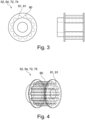
Fig. 3 illustrates a sectional view of a coil of a belt actuator system with a belt zipper system according to an embodiment of the present invention; -
Fig. 4 illustrates a coil of the belt zipper system in a perspective view according to an embodiment of the present invention; -
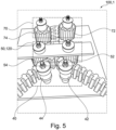
Fig. 5 illustrates a schematic example of a belt actuator system with a belt zipper system according to an embodiment of the present invention; -
Fig. 5-1 illustrates a schematic example of a belt actuator system with a belt zipper system according to an embodiment of the present invention; -
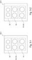
Fig. 5-2 illustrates a schematic example of a belt actuator system with a belt zipper system according to an embodiment of the present invention; -
Fig. 5-3 illustrates a schematic example of a belt actuator system with a belt zipper system according to an embodiment of the present invention; -
Fig. 5-4 illustrates a schematic example of a belt actuator system with a belt zipper system according to an embodiment of the present invention; and -
Fig. 6 illustrates a schematic example of a winded belt according to an embodiment of the present invention. -
Fig. 1 illustrates a schematic example of a belt actuator system 100 with a belt zipper system 1 according to an embodiment of the present invention. - The belt zipper system 1 is configured to form a
third belt element 30 in a zip-fastening manner of afirst belt element 10 and asecond belt element 20. - The belt zipper system 1 comprises a guiding
arrangement element 42 and at least a second movable guidingelement 44 arranged in a samefirst plane 46 configured to move thefirst belt element 10 and thesecond belt element 20 in a synchronous manner. - According to
Fig. 1 , the guidingarrangement Fig. 1 comprises anactuating unit 48 to move the first guidingelement 42 and / or thesecond guiding element 44 of the guidingarrangement 40. - The belt zipper system 1 further comprises a first zip-
fastening arrangement 50 omprising a firstmovable coil 52 and a secondmovable coil 54 arranged in a samesecond plane 56, wherein the first zip-fastening arrangement 50 is configured to connect afirst part 12 of thefirst belt element 10 with asecond part 14 of thesecond belt element 20 in a zip-like manner to obtain the third zip-fastenedbelt element 30. - In this respect, it should be noted that alternatively, the belt actuator system 100 may comprise a drive unit 120 to drive the first zip-
fastening arrangement 50 and itscorresponding coils actuating unit 48. - Further, in an example, the drive unit 120 is connected to the first zip-
fastening arrangement 50 configured to drive the first zip-fastening arrangement 50 and / or is connected to the second zip-fastening arrangement 70 configured to drive the second zip-fastening arrangement 70. - The drive unit 120 may comprise a single motor or a plurality of motors (not shown in
Fig. 1 ). - In the belt zipper system 1, the
first plane 46 of the guidingarrangement first distance 60 to thesecond plane 56 of the first zip-fastening arrangement - Optionally, the defined
first distance 60 of thefirst plane 46 of the guidingarrangement second plane 56 of the first zip-fastening arrangement 50 in a defined horizontal and / or vertical direction. - According to
Fig. 1 , the belt zipper system 1 comprises a second zip-fastening arrangement 70 comprising a thirdmovable coil 72 and a fourthmovable coil 74 arranged in a samethird plane 76, wherein thethird plane 76 is arranged in a secondhorizontal distance 78 to thesecond plane 56 of the first zip-fastening arrangement 50. - As the
Fig. 1 shows, the first guidingelement 42 and at least asecond guiding element 44 of the guidingarrangement 40 have a defineddistance 49 in horizontal direction of thefirst plane 46. - According to
Fig. 1 , the thebelt elements belt surface 80 having a plurality of tooth-like form elements 81. - According to
Fig. 1 in combination withFig. 3 and 4 , thecoils fastening arrangements coil surface 90 having a plurality of tooth-like form elements 91 that is identical to thebelt surface 80 of thebelt elements - According to a further and more detailed example of the belt actuator system 100 and as shown in
Fig. 1 , the belt actuator system 100 comprises at least a drive unit 120 and a belt zipper system 1 configured to form athird belt element 30 in a zip-fastening manner of afirst belt element 10 and asecond belt element 20. - The belt zipper system 1 further comprises:
- a guiding
arrangement element 42 and at least a second movable guidingelement 44 arranged in a samefirst plane 46 configured to move thefirst belt element 10 and thesecond belt element 20 in a synchronous manner; - a first zip-
fastening arrangement 50 comprising a firstmovable coil 52 and a secondmovable coil 54 arranged in a samesecond plane 56, wherein the first zip-fastening arrangement 50 is configured to connect afirst part 12 of thefirst belt element 10 with asecond part 14 of thesecond belt element 20 in a zip-like manner to obtain the third zip-fastenedbelt element 30, and - wherein the
first plane 46 of the guidingarrangement first distance 60 to thesecond plane 56 of the first zip-fastening arrangement 50, - a second zip-
fastening arrangement 70 comprising a thirdmovable coil 72 and a fourthmovable coil 74 arranged in a samethird plane 76, wherein thethird plane 76 is arranged in a secondhorizontal distance 78 to thesecond plane 56 of the first zip-fastening arrangement 50, - wherein the drive unit 120 is connected to the first zip-
fastening arrangement 50 configured to drive the first zip-fastening arrangement 50 and / or is connected to the second zip-fastening arrangement 70 configured to drive the second zip-fastening arrangement 70. - According to
Fig. 1 , the actuatingunit 48 is a motor enabling to move the bothbelt elements - The
belt elements - In this context, it should be noted that the lose ends of the belt may be winded up by using a preferred system, e.g. actively-driven or passive system (not shown in the figures). The winding of the belt ends may be done in a same plane or in a different plane. In this respect,
Fig. 6 shows an example for belts that are winded up. -
Fig. 2 illustrates a schematic example of a belt actuator system 100 with a belt zipper system 1 according to an embodiment of the present invention. In principle, the embodiment ofFig. 2 shows the same belt zipper system 1 ofFig. 1 only in another perspective view without the drive unit 120 and theactuating unit 48. -
Fig. 3 illustrates a sectional view of acoil coil coil surface 90 which is configured to have cavities in which the tooth-like form element 81, 91 of thebelt element -
Fig. 4 illustrates acoil coil surface 90 in a perspective view according to an embodiment of the present invention. -
Fig. 5 illustrates a schematic example of a belt actuator system 100 with a belt zipper system 1 according to an embodiment of the present invention. In principle, the belt actuator system 100 is identical to the embodiment shown inFig. 1 . However, in the embodiment ofFig. 5 , no actuatingunit 48 is inserted. Instead, as a further example, a drive unit 120 is implemented driving the first zip-fastening-arrangement 50. The drive unit 120 may comprise a single motor or a plurality of motors (not shown inFig. 5 ) to either drive one coil or to drive both coils of the twocoils coils - The motor used for tractional gears may be a stepper motor providing the functionality of backdrivability of the system or / and may be a DC motor not providing the functionality of backdrivability of the system.
- For the following
figures 5-1 to 5-4 , it is noted that for ease of understanding, the corresponding coils 42, 44 of the guidingarrangement 40, thecoils fastening arrangement 50 and thecoils fastening arrangement 70 as shown inFig. 1 ,2 and5 are not depicted in thefigures 5-1 to 5-4 . -
Fig. 5-1 illustrates a schematic example of a belt actuator system 100 with a belt zipper system 1 according to an embodiment of the present invention. In this embodiment, the drive unit 120 is configured to actively drive coils 52, 54 of the first zip-fastening arrangement 50. The drive unit 120 may be configured as a or more tractional gear elements connected to one or more motors (not shown). Thecoils arrangement 40 are configured as passive rollers or fix guides. Thecoils fastening arrangement 70 are configured as passive tractional gear elements not connected to a motor. -
Fig. 5-2 illustrates a further schematic example of a belt actuator system 100 with a belt zipper system 1 according to an embodiment of the present invention. In this embodiment, the drive unit 120 is configured to actively drive coils 72, 74 of the second zip-fastening arrangement 70 and is embodied as a tractional gear element connected to a motor unit (not shown). Thecoils arrangement 40 are configured as passive rollers or fix guides and thecoils fastening arrangement 50 are configured as passive tractional gear elements not connected to a motor. -
Fig. 5-3 illustrates a schematic example of a belt actuator system 100 with a belt zipper system 1 according to an embodiment of the present invention. In this embodiment, the drive unit 120 is configured to actively drive coils 52, 54 of the first zip-fastening arrangement 50. The drive unit 120 may be configured as tractional gear elements connected to one or more motors (not shown). Thecoils arrangement 40 and thecoils fastening arrangement 70 are configured as passive rollers or fix guides. -
Fig. 5-4 illustrates a further schematic example of a belt actuator system 100 with a belt zipper system 1 according to an embodiment of the present invention. In this embodiment, the drive unit 120 is configured to actively drive coils 52, 54 of the first zip-fastening arrangement 50. The drive unit 120 may be configured as tractional gear elements connected to one or more motors (not shown) to drive thecoils fastening arrangement 50. Thecoils arrangement 40 and thecoils fastening arrangement 70 are configured as passive rollers or fix guides. - In regard of the embodiments of
Fig 5-1, 5-2 ,5-3 and 5-4 , it should be further noted that the diameter of the passive rollers or fix guides can be of any size that is suitable for the choosed application. - List of reference signs
- 1
- Belt zipper system
- 10
- First belt element
- 12
- First part
- 14
- Second part
- 20
- Second belt element
- 22
- First guiding element
- 24
- Second guiding element
- 30
- Third belt element
- 40
- Guiding arrangement
- 42
- First guiding element
- 44
- Second guiding element
- 46
- First plane
- 48
- Actuating unit
- 49
- Distance between guiding elements
- 50
- First zip-fastening arrangement
- 52
-
First coil 52 - 54
- Second coil
- 56
- Second plane
- 60
- First distance
- 70
- Second zip-fastening arrangement
- 72
- Third coil
- 74
- Fourth coil
- 76
- Third plane
- 78
- Second distance
- 80
- Belt surface
- 81, 91
- Tooth-like form element of the belt element
- 90
- Coil surface
- 95
- Platform
- 120
- Drive unit
Claims (9)
- A belt actuator system (100) comprising:at least a drive unit (120),a belt zipper system (1) configured to form a third belt element (30) in a zip-fastening manner of a first belt element (10) and a second belt element (20) comprising:- a guiding arrangement (40, 42, 44) configured to move the first belt element (10) and the second belt element (20) in a synchronous manner;- a first zip-fastening arrangement (50), wherein the first zip-fastening arrangement (50) is configured to connect a first part (12) of the first belt element (10) with a second part (14) of the second belt element (20) in a zip-like manner to obtain the third zip-fastened belt element (30), and- wherein the drive unit (120) is connected to the first zip-fastening arrangement (50) configured to drive the first zip-fastening arrangement (50).
- The belt actuator system (100) according to claim 1, wherein the defined first distance (60) of the first plane (46) of the guiding arrangement (40, 42, 44) related to the second plane (56) of the first zip-fastening arrangement (50) in a defined horizontal and / or vertical direction.
- The belt actuator system (100) according to any of the previous claims, wherein the guiding arrangement (40, 42, 44) comprises an actuating unit (48) to move the first guiding element (42) and / or the second guiding element (44) of the guiding arrangement (40).
- The belt actuator system (100) according to any of the previous claims, wherein the first guiding element (42) and at least a second guiding element (44) of the guiding arrangement (40) have a defined distance (49) in horizontal direction of the first plane (46).
- The belt actuator system (100) according to any of the previous claims, wherein the belt elements (10, 20) comprise a belt surface (80) having a plurality of tooth-like form elements (81).
- The belt actuator system (100) according to any of the previous claims, wherein the coils (50, 52) of the first zip-fastening arrangement (50) comprises each a coil surface (90) having a plurality of tooth-like form elements (91) that is identical to the belt surface (80) of the belt elements (10, 20).
- The belt actuator system (100) according to any of the previous claims, wherein the actuating unit (48) is a motor enabling to move the both belt elements (10, 20) in synchronous manner.
- The belt actuator system (100) according to any of the previous claims, wherein the belt elements (10, 20) are of a same material.
- A belt system, comprising a belt actuator system (100) according to any of the previous claims.
Priority Applications (2)
| Application Number | Priority Date | Filing Date | Title |
|---|---|---|---|
| EP23188499.0A EP4497972A1 (en) | 2023-07-28 | 2023-07-28 | Belt actuator system |
| US18/785,468 US20250035202A1 (en) | 2023-07-28 | 2024-07-26 | Belt Actuator System |
Applications Claiming Priority (1)
| Application Number | Priority Date | Filing Date | Title |
|---|---|---|---|
| EP23188499.0A EP4497972A1 (en) | 2023-07-28 | 2023-07-28 | Belt actuator system |
Publications (1)
| Publication Number | Publication Date |
|---|---|
| EP4497972A1 true EP4497972A1 (en) | 2025-01-29 |
Family
ID=87520019
Family Applications (1)
| Application Number | Title | Priority Date | Filing Date |
|---|---|---|---|
| EP23188499.0A Pending EP4497972A1 (en) | 2023-07-28 | 2023-07-28 | Belt actuator system |
Country Status (2)
| Country | Link |
|---|---|
| US (1) | US20250035202A1 (en) |
| EP (1) | EP4497972A1 (en) |
Citations (4)
| Publication number | Priority date | Publication date | Assignee | Title |
|---|---|---|---|---|
| US2554300A (en) * | 1947-08-29 | 1951-05-22 | Hayakawa Yaichi | Interlocking chain stanchion |
| US6419603B1 (en) * | 1997-04-15 | 2002-07-16 | Andreas Grasl | Device for transmitting a force, in particular a compression force, along a substantially straight path |
| US20150082582A1 (en) * | 2013-09-22 | 2015-03-26 | Massachusetts Institute Of Technology | Methods and Apparatus for Robotic Zipper |
| DE102020105040A1 (en) * | 2020-02-26 | 2021-08-26 | Otto-Von-Guericke-Universität Magdeburg | Adjustment mechanism and procedure for its operation |
Family Cites Families (10)
| Publication number | Priority date | Publication date | Assignee | Title |
|---|---|---|---|---|
| US2375462A (en) * | 1938-02-04 | 1945-05-08 | Bender Karl | Compression resistant group of flat link chains |
| CA2087441A1 (en) * | 1990-07-16 | 1992-01-17 | Michael Patrick Mcdonnell | Extendable mast support system |
| DE4126201C2 (en) * | 1991-08-08 | 1995-10-12 | Rheinmetall Ind Gmbh | Chain attachment |
| DE4131762C2 (en) * | 1991-09-24 | 1997-05-22 | Winkhaus Fa August | Actuating device for a wing of a window, a door, a ventilation flap or the like |
| US5355643A (en) * | 1991-10-04 | 1994-10-18 | Alain Burri Sa | Transformable structural element |
| CH690278A5 (en) * | 1994-04-14 | 2000-06-30 | Serge Alain Bringolf | Element transformable structure. |
| FR2826422B1 (en) * | 2001-06-26 | 2003-11-14 | Serapid France | LINEAR BELT ACTUATOR |
| JP4897093B1 (en) * | 2011-01-27 | 2012-03-14 | 株式会社椿本チエイン | Engagement chain type advance / retreat actuator |
| CN104894996B (en) * | 2015-06-18 | 2016-05-11 | 合肥工业大学 | A One-way Bending Transmission Chain and Its Application |
| JP6078672B1 (en) * | 2016-02-22 | 2017-02-08 | 株式会社椿本チエイン | Meshing chain and movable body moving device |
-
2023
- 2023-07-28 EP EP23188499.0A patent/EP4497972A1/en active Pending
-
2024
- 2024-07-26 US US18/785,468 patent/US20250035202A1/en active Pending
Patent Citations (4)
| Publication number | Priority date | Publication date | Assignee | Title |
|---|---|---|---|---|
| US2554300A (en) * | 1947-08-29 | 1951-05-22 | Hayakawa Yaichi | Interlocking chain stanchion |
| US6419603B1 (en) * | 1997-04-15 | 2002-07-16 | Andreas Grasl | Device for transmitting a force, in particular a compression force, along a substantially straight path |
| US20150082582A1 (en) * | 2013-09-22 | 2015-03-26 | Massachusetts Institute Of Technology | Methods and Apparatus for Robotic Zipper |
| DE102020105040A1 (en) * | 2020-02-26 | 2021-08-26 | Otto-Von-Guericke-Universität Magdeburg | Adjustment mechanism and procedure for its operation |
Also Published As
| Publication number | Publication date |
|---|---|
| US20250035202A1 (en) | 2025-01-30 |
Similar Documents
| Publication | Publication Date | Title |
|---|---|---|
| KR100359704B1 (en) | Iron core assembly | |
| CN101326702B (en) | Linear motor actuator | |
| US20170184190A1 (en) | Flex spline torque transfer device | |
| EP0482321A1 (en) | A combined linear-rotary direct drive step motor | |
| AU2018329195B2 (en) | High reduction belt-driven linear actuator | |
| US11391366B2 (en) | Electromagnetically operated band brake | |
| EP3131775B1 (en) | Electric drive, method for the operation thereof, and serial hybrid drive train for a motor vehicle | |
| US11446829B2 (en) | Robot arm extension device and robot including same | |
| DE4115728C2 (en) | Elevator with linear motor drive | |
| DE69214981T2 (en) | Elevator driven by a flat linear motor | |
| EP0269649B1 (en) | Linear unit for handling devices | |
| EP3681835B1 (en) | Elevator system | |
| DE69814356T2 (en) | Brushless permanent magnet electric motor | |
| US20250035202A1 (en) | Belt Actuator System | |
| DE202015009360U1 (en) | elevator | |
| US11336165B2 (en) | Curvilinear motor | |
| JPH1170487A (en) | robot | |
| US20250122923A1 (en) | Annular pulley system | |
| US20220136592A1 (en) | Linear actuator and construction kit for producing said linear actuator | |
| EP1675251B1 (en) | Tube motor for window blinds | |
| JP4662502B2 (en) | Meshing chain | |
| CN215334257U (en) | Chain mast with screw drive | |
| DE102014001922A1 (en) | Motor series and method for creating the motor series | |
| DE69917014T2 (en) | Improvements in or relating to rotary actuators | |
| DE10036913B4 (en) | Escalator or moving walk drive |
Legal Events
| Date | Code | Title | Description |
|---|---|---|---|
| PUAI | Public reference made under article 153(3) epc to a published international application that has entered the european phase |
Free format text: ORIGINAL CODE: 0009012 |
|
| STAA | Information on the status of an ep patent application or granted ep patent |
Free format text: STATUS: THE APPLICATION HAS BEEN PUBLISHED |
|
| AK | Designated contracting states |
Kind code of ref document: A1 Designated state(s): AL AT BE BG CH CY CZ DE DK EE ES FI FR GB GR HR HU IE IS IT LI LT LU LV MC ME MK MT NL NO PL PT RO RS SE SI SK SM TR |
|
| STAA | Information on the status of an ep patent application or granted ep patent |
Free format text: STATUS: REQUEST FOR EXAMINATION WAS MADE |
|
| 17P | Request for examination filed |
Effective date: 20250724 |
|
| STAA | Information on the status of an ep patent application or granted ep patent |
Free format text: STATUS: EXAMINATION IS IN PROGRESS |
|
| 17Q | First examination report despatched |
Effective date: 20260317 |