EP4497952A1 - Centrifugal blower - Google Patents
Centrifugal blower Download PDFInfo
- Publication number
- EP4497952A1 EP4497952A1 EP23774875.1A EP23774875A EP4497952A1 EP 4497952 A1 EP4497952 A1 EP 4497952A1 EP 23774875 A EP23774875 A EP 23774875A EP 4497952 A1 EP4497952 A1 EP 4497952A1
- Authority
- EP
- European Patent Office
- Prior art keywords
- impeller
- centrifugal blower
- planar portion
- peripheral wall
- clearance
- Prior art date
- Legal status (The legal status is an assumption and is not a legal conclusion. Google has not performed a legal analysis and makes no representation as to the accuracy of the status listed.)
- Pending
Links
Images

Classifications
-
- F—MECHANICAL ENGINEERING; LIGHTING; HEATING; WEAPONS; BLASTING
- F04—POSITIVE - DISPLACEMENT MACHINES FOR LIQUIDS; PUMPS FOR LIQUIDS OR ELASTIC FLUIDS
- F04D—NON-POSITIVE-DISPLACEMENT PUMPS
- F04D17/00—Radial-flow pumps, e.g. centrifugal pumps; Helico-centrifugal pumps
- F04D17/08—Centrifugal pumps
- F04D17/16—Centrifugal pumps for displacing without appreciable compression
-
- F—MECHANICAL ENGINEERING; LIGHTING; HEATING; WEAPONS; BLASTING
- F04—POSITIVE - DISPLACEMENT MACHINES FOR LIQUIDS; PUMPS FOR LIQUIDS OR ELASTIC FLUIDS
- F04D—NON-POSITIVE-DISPLACEMENT PUMPS
- F04D29/00—Details, component parts, or accessories
- F04D29/40—Casings; Connections of working fluid
- F04D29/42—Casings; Connections of working fluid for radial or helico-centrifugal pumps
- F04D29/4206—Casings; Connections of working fluid for radial or helico-centrifugal pumps especially adapted for elastic fluid pumps
- F04D29/4226—Fan casings
-
- F—MECHANICAL ENGINEERING; LIGHTING; HEATING; WEAPONS; BLASTING
- F04—POSITIVE - DISPLACEMENT MACHINES FOR LIQUIDS; PUMPS FOR LIQUIDS OR ELASTIC FLUIDS
- F04D—NON-POSITIVE-DISPLACEMENT PUMPS
- F04D29/00—Details, component parts, or accessories
- F04D29/66—Combating cavitation, whirls, noise, vibration or the like; Balancing
- F04D29/661—Combating cavitation, whirls, noise, vibration or the like; Balancing especially adapted for elastic fluid pumps
- F04D29/663—Sound attenuation
Definitions
- a typical centrifugal blower (hereinafter referred to as conventional centrifugal blower) is arranged in, for example, an exhaust passage and an air supply passage. Clogging of a filter arranged in the exhaust passage or the air supply passage increases the load applied to the conventional centrifugal blower and causes the centrifugal blower to surge.
- Patent Literature 1 describes a centrifugal blower having high static pressure characteristics in a low gas flow rate region.
- the centrifugal blower described in Patent Literature 1 has a constricted portion (closest portion in Patent Literature 1) where a passage is narrowed in a scroll casing. Noise may be generated at the constricted portion.
- Patent Literature 2 A technique related to noise suppression in a centrifugal blower is known (for example, Patent Literature 2).
- this technique is for a conventional centrifugal blower.
- it is uncertain whether this technique is effective for reducing surges in a centrifugal blower having high static pressure characteristics in a low gas flow rate region.
- this technique is effective for reducing surges in a centrifugal blower having high static pressure characteristics in a low gas flow rate region.
- a centrifugal blower that solves the above problem includes an impeller, and a scroll casing accommodating the impeller.
- the impeller is configured to draw in gas through an opening in a side surface and send out the gas in a centrifugal direction.
- the scroll casing includes an inlet that draws in the gas, an outlet that blows out the gas sent out from the impeller, a peripheral wall arranged along an outer circumference of the impeller, and a tongue that guides the gas flowing along the peripheral wall to the outlet.
- the peripheral wall of the scroll casing includes a first planar portion extending continuously from the tongue, and a second planar portion located at a position advanced from the first planar portion in a rotation direction of the impeller.
- the peripheral wall of the scroll casing includes the narrowest portion of the clearance in the passage at a position advanced from the tongue in the rotation direction of the impeller.
- the clearance in the proximity of the tongue is greater than the clearance in the proximity of the narrowest portion.
- the flow of gas in the passage may stagnate from the tongue to the narrowest portion.
- the gas flow stagnation will generate noise.
- the first planar portion is arranged at the tongue, and the second planar portion is arranged at the narrowest portion. This rectifies the flow of gas in the range from the tongue to the narrowest portion and alleviates the stagnation of the flow of gas. Thus, surges are reduced and the generation of noise is suppressed.
- a ratio of the first clearance to the second clearance is in a range from 1.5 to 2.5, inclusive.
- the passage When the ratio of the first clearance to the second clearance is greater than 2.5, the passage will be narrowed excessively from the tongue to the narrowest portion. Thus, the flow of gas is apt to stagnate, thereby generating noise in the proximity of the narrowest portion.
- the ratio of the first clearance to the second clearance is less than 1.5, the passage will be narrowed to a small degree from the tongue to the narrowest portion. In this case, the size of the clearance in the proximity of the tongue, which is the entrance of the passage, will be close to the size of the clearance at the narrowest portion. Thus, the passage will be narrow from the tongue to the narrowest portion, thereby hindering the flow of gas. As a result, turbulence will be apt to be generated in the proximity of the tongue. This will lower the surge reducing effect.
- the above-described structure reduces turbulence in the proximity of the tongue and alleviates gas flow stagnation in the proximity of the narrowest portion. This effectively reduces surges and suppresses the generation of noise.
- an angle from the first perpendicular line to the second perpendicular line in a rotation direction of the impeller is in a range from 80 degrees to 110 degrees, inclusive.
- the centrifugal blower has higher static pressure characteristics than when the angle is less than 80 degrees or greater than 110 degrees.
- an angle from the first perpendicular line to the second perpendicular line in a rotation direction of the impeller is in a range from 20 degrees to 40 degrees, inclusive.
- the centrifugal blower has a higher static pressure efficiency than when the angle is less than 20 degrees or greater than 40 degrees.
- a quantity of blades of the impeller is 60 or greater.
- an increase in the quantity of the blades will have a poor effect on increasing the static pressure in a low gas flow rate region (high load region).
- an increase in the quantity of the blades has an effect on increasing the static pressure in the low gas flow rate region regarding the gas flow rate-static pressure characteristics.
- the centrifugal blower having the above-described structure has a higher static pressure in the low gas flow rate region than a centrifugal blower having 40 blades.
- the centrifugal blower 1 includes a sirocco fan, a limit load fan, and a turbo fan.
- the centrifugal blower 1 is, for example, a sirocco fan.
- the centrifugal blower 1 is arranged in an air conditioner or a blower.
- the gas is air.
- the gas includes air, argon gas, oxygen gas, and nitrogen gas.
- a view of the centrifugal blower 1 in a direction extending along the center axis C of the shaft 11 is referred to as side view.
- the centrifugal blower 1 includes an impeller 2 and a scroll casing 3 that accommodates the impeller 2.
- the impeller 2 is configured to draw in gas through an opening 15 in a side surface and send out the gas in a centrifugal direction.
- the impeller 2 includes a shaft 11, a base 12 fixed to the shaft 11, blades 13 arranged on the base 12, and a ring 14 coupling the blades 13.
- the shaft 11 is fixed to an output shaft of a motor 40.
- the base 12 is formed by a disk of which the center is the center axis C of the shaft 11.
- the blades 13 are arranged at predetermined intervals along the outer circumference of the base 12.
- the blades 13 are arranged so that the longitudinal direction of each blade 13 is parallel to the shaft 11.
- the blades 13 each include a first end 13A that is connected to the base 12, and a second end 13B that is opposite to the first end 13A and connected to the ring 14.
- the impeller 2 includes the opening 15 (refer to Fig.
- the opening 15 is arranged within the ring 14. In other words, the opening 15 is defined by the inner circumference of the ring 14. The opening 15 overlaps an inlet 25 of the scroll casing 3 in a state in which the impeller 2 is accommodated in the scroll casing 3 in side view. The opening 15 is open toward the space outside the scroll casing 3.
- the quantity of the blades 13 of the impeller 2 is 40 or greater. In one example, the quantity of the blades 13 of the impeller 2 is 60 or greater.
- the quantity of the blades 13 of the impeller 2 is preferably a prime number. For example, the quantity of the blades 13 of the impeller 2 is 41, 51, or 61.
- the scroll casing 3 accommodates the impeller 2.
- the scroll casing 3 includes a first side wall 21, a second side wall 22 similar in shape to the first side wall 21, and a peripheral wall 23.
- the scroll casing 3 further includes the outlet 24, the inlet 25, and the tongue 26.
- the first side wall 21 and the second side wall 22 form the side surfaces of the scroll casing 3.
- the peripheral wall 23 is arranged along the outer circumference of the impeller 2. Specifically, the peripheral wall 23 is arranged between the first side wall 21 and the second side wall 22. The peripheral wall 23 is arranged along the edge of the first side wall 21 and the edge of the second side wall 22. The peripheral wall 23 connects the first side wall 21 and the second side wall 22.
- the peripheral wall 23 extends in a spiral manner about the center axis C of the shaft 11.
- the peripheral wall 23 forms the passage 28 of gas between the peripheral wall 23 and the impeller 2.
- a passage cross-sectional area refers to the area of a cross-section when the passage 28 is cut along a plane including the center axis C of the shaft 11.
- the passage cross-sectional area gradually decreases from a downstream end 31B of a first planar portion 31 to an upstream end 32A of a second planar portion 32.
- the passage cross-sectional area gradually increases from a downstream end 32B of the second planar portion 32 toward the outlet 24.
- the inlet 25 is formed in the first side wall 21 or the second side wall 22. In the present embodiment, the inlet 25 is formed in the first side wall 21.
- the inlet 25 is formed by a bell mouth.
- the inlet 25 is circular.
- the inlet 25 has substantially the same size as the opening 15 of the impeller 2.
- the center of the inlet 25 is located at the same position as the center axis C of the shaft 11.
- the outlet 24 is the part where gas is blown out of the impeller 2.
- the outlet 24 is tubular.
- the outlet 24 is arranged at a downstream end 23B of the peripheral wall 23.
- the tongue 26 guides the gas flowing along the peripheral wall 23 to the outlet 24.
- the tongue 26 is continuous with an upstream end 23A of the peripheral wall 23.
- the upstream end 23A of the peripheral wall 23 is the same part as an upstream end 31A of the first planar portion 31.
- the peripheral wall 23 includes the first planar portion 31 and the second planar portion 32.
- the first planar portion 31 extends continuously from the tongue 26.
- the first planar portion 31 is orthogonal to a straight line extending from the center CA of the impeller 2.
- the second planar portion 32 is located at a position advanced from the first planar portion 31 in the rotation direction of the impeller 2.
- the second planar portion 32 is orthogonal to a straight line extending from the center CA of the impeller 2.
- the peripheral wall 23 is configured so that a clearance CL in the passage 28 is minimal at the second planar portion 32.
- the clearance CL is defined as the difference between the distance from the center CA of the impeller 2 to an inner surface 23C of the peripheral wall 23 and the distance from the center CA of the impeller 2 to the outer surface 2A of the impeller 2.
- the outer surface 2A of the impeller 2 is a surface formed by connecting the outer ends of the blades 13.
- the clearance CL is substantially equal to a value obtained by subtracting the radius R of the impeller 2 from the distance from the center CA of the impeller 2 to the inner surface 23C of the peripheral wall 23 on a line extending in the radial direction.
- a narrowest portion 33 where the clearance CL at the second planar portion 32 is minimal is located between the upstream end 32A and the downstream end 32B of the second planar portion 32.
- the distance between the narrowest portion 33 and the downstream end 32B of the second planar portion 32 is greater than the distance between the narrowest portion 33 and the upstream end 32A of the second planar portion 32.
- the narrowest portion 33 in the second planar portion 32 may be the upstream end 32A of the second planar portion 32.
- the narrowest portion 33 in the second planar portion 32 may be the downstream end 32B of the second planar portion 32.
- an angle A3 between a line connecting the center CA of the impeller 2 and the upstream end 31A of the first planar portion 31 and a line connecting the center CA of the impeller 2 and the downstream end 31B of the first planar portion 31 is in a range from 5 degrees to 20 degrees, inclusive.
- an angle A4 between a line connecting the center CA of the impeller 2 and the upstream end 32A of the second planar portion 32 and a line connecting the center CA of the impeller 2 and the downstream end 32B of the second planar portion 32 is in a range from 5 degrees to 30 degrees, inclusive.
- a line extending from the center of the impeller 2 to the first planar portion 31 in side view is defined as a first perpendicular line L1.
- a line extending from the center of the impeller 2 to the second planar portion 32 in side view is defined as a second perpendicular line L2.
- the ratio of a first clearance CL1 to a second clearance CL2 is preferably in a range from 1.5 to 2.5, inclusive.
- the first clearance CL1 is defined as a value obtained by subtracting the radius R of the impeller 2 from the length of the first perpendicular line L1.
- the second clearance CL2 is defined as a value obtained by subtracting the radius R of the impeller 2 from the length of the second perpendicular line L2.
- the first perpendicular line L1 extends proximate to the tongue 26.
- the second perpendicular line L2 has the following relationship with the first perpendicular line L1.
- An angle A1 from the first perpendicular line L1 to the second perpendicular line L2 in the rotation direction of the impeller 2 is in a range from 80 degrees to 110 degrees, inclusive.
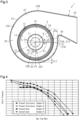
- Fig. 4 shows the static pressure-gas flow rate characteristics of the centrifugal blower 1.
- the line plotting black dots indicates the characteristics of the centrifugal blower 1 of the present embodiment that has 61 blades 13.
- the line plotting white dots indicates the characteristics of the centrifugal blower 1 of the present embodiment that has 41 blades 13.
- the line plotting black squares indicates the characteristics of a centrifugal blower of a referential example having 61 blades 13.
- the line plotting white squares indicates the characteristics of the centrifugal blower of the referential example that has 41 blades 13.
- the centrifugal blower of the referential example differs from the centrifugal blower 1 of the present embodiment in the following points.
- the centrifugal blower of the referential example includes the first planar portion 31 but not the second planar portion 32. Except in that there is no second planar portion 32, the centrifugal blower of the referential example has the same structure as the centrifugal blower 1 of the present embodiment.
- the centrifugal blower 1 of the present embodiment has a higher static pressure in a low gas flow rate region than the centrifugal blower of the referential example.
- the centrifugal blower 1 of the present embodiment can be applied in a preferred manner to a discharge portion of a device including a high efficiency particulate air filter (HEPA filter).
- HEPA filter high efficiency particulate air filter
- the static pressure characteristics in the low gas flow rate region can be adjusted by the quantity of the blades 13 that is set.
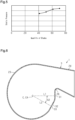
- Fig. 5 shows the static pressure of centrifugal blowers 1 having different quantities of the blades 13 in the present embodiment when the gas flow rate is 2 m 3 /min.
- the horizontal axis represents the quantity of the blades 13.
- the vertical axis represents the static pressure.
- the static pressure in the low gas flow rate region increases as the quantity of the blades 13 increases.
- the gas blown out of the impeller 2 is apt to directly strike the tongue 26. This will cause turbulence in the proximity of the tongue 26.
- the first planar portion 31 is arranged continuously with the tongue 26. In the passage 28, the clearance CL at the first planar portion 31 is greater than the clearance CL at the second planar portion 32.
- the tongue 26 is located farther from the impeller 2 than the conventional centrifugal blower. This reduces turbulence in the proximity of the tongue 26.
- the passage cross-sectional area is gradually decreased.
- the gas blown out of the impeller 2 into the path from the first planar portion 31 to the second planar portion 32 will stagnate at the narrowest portion 33 of the passage 28 and causes turbulence.
- the second planar portion 32 is arranged in the narrowest portion 33 of the passage 28. This alleviates the stagnation of the flow of gas.
- the first planar portion 31 allows gas to flow smoothly in the path from the first planar portion 31 to the second planar portion 32. As a result, the flow of gas is rectified in a range from the tongue 26 to the narrowest portion 33, thereby alleviating gas flow stagnation. This reduces surges and suppresses the generation of noise.
- centrifugal blower 1 of the present disclosure an increase in the quantity of the blades 13 has an effect on increasing the static pressure in the low gas flow rate region regarding the gas flow rate-static pressure characteristics.
- the centrifugal blower 1 having the above-described structure has a higher static pressure in the low gas flow rate region than the centrifugal blower 1 having 40 blades 13.
- centrifugal blower 1 of the present disclosure may be, for example, modified as illustrated in the examples described below or be implemented by combining at least two of the modified examples as long as they do not contradict each other.
- the centrifugal blower 1 of a modified example will now be described with reference to Fig. 6 .
- the angle A1 from the first perpendicular line L1 to the second perpendicular line L2 in the rotation direction of the impeller 2 is in the range from 80 degrees to 110 degrees, inclusive.
- an angle A2 from the first perpendicular line L1 to the second perpendicular line L2 in the rotation direction of the impeller 2 may be set in a range from 20 degrees to 40 degrees, inclusive.
- the centrifugal blower 1 has a higher static pressure efficiency than when the angle A2 is less than 20 degrees or greater than 40 degrees.
- the static pressure efficiency is expressed as gas flow rate ⁇ static pressure/(60 ⁇ shaft power).
- centrifugal blower 1 according to the embodiment has been described above, it will be understood that various changes in modes and details can be made without departing from the spirit and scope of the centrifugal blower 1 in the claims.
Landscapes
- Engineering & Computer Science (AREA)
- Mechanical Engineering (AREA)
- General Engineering & Computer Science (AREA)
- Structures Of Non-Positive Displacement Pumps (AREA)
Abstract
Description
- The present disclosure relates to a centrifugal blower.
- A typical centrifugal blower (hereinafter referred to as conventional centrifugal blower) is arranged in, for example, an exhaust passage and an air supply passage. Clogging of a filter arranged in the exhaust passage or the air supply passage increases the load applied to the conventional centrifugal blower and causes the centrifugal blower to surge.
-
- Patent Literature 1: International Patent Publication No.
WO2019/146015 - Patent Literature 2:
Japanese Laid-Open Patent Publication No. 2003-35298 -
Patent Literature 1 describes a centrifugal blower having high static pressure characteristics in a low gas flow rate region. The centrifugal blower described inPatent Literature 1 has a constricted portion (closest portion in Patent Literature 1) where a passage is narrowed in a scroll casing. Noise may be generated at the constricted portion. - A technique related to noise suppression in a centrifugal blower is known (for example, Patent Literature 2). However, this technique is for a conventional centrifugal blower. Thus, it is uncertain whether this technique is effective for reducing surges in a centrifugal blower having high static pressure characteristics in a low gas flow rate region. In this manner, there is room for improvement in the suppression of noise and the reduction of surges in the centrifugal blower having high static pressure characteristics in a low gas flow rate region. Solution to Problem
- A centrifugal blower that solves the above problem includes an impeller, and a scroll casing accommodating the impeller. The impeller is configured to draw in gas through an opening in a side surface and send out the gas in a centrifugal direction. The scroll casing includes an inlet that draws in the gas, an outlet that blows out the gas sent out from the impeller, a peripheral wall arranged along an outer circumference of the impeller, and a tongue that guides the gas flowing along the peripheral wall to the outlet. The peripheral wall of the scroll casing includes a first planar portion extending continuously from the tongue, and a second planar portion located at a position advanced from the first planar portion in a rotation direction of the impeller. The peripheral wall is configured so that a clearance, that is a difference between a distance from a center of the impeller to an inner surface of the peripheral wall and a distance from the center of the impeller to an outer surface of the impeller in a passage along the peripheral wall, is minimal at the second planar portion.
- In the above-described centrifugal blower, the peripheral wall of the scroll casing includes the narrowest portion of the clearance in the passage at a position advanced from the tongue in the rotation direction of the impeller. Thus, the clearance in the proximity of the tongue is greater than the clearance in the proximity of the narrowest portion. This limits turbulence in the proximity of the tongue and reduces the generation of surges. The flow of gas in the passage may stagnate from the tongue to the narrowest portion. The gas flow stagnation will generate noise. In this respect, with the above-described structure, the first planar portion is arranged at the tongue, and the second planar portion is arranged at the narrowest portion. This rectifies the flow of gas in the range from the tongue to the narrowest portion and alleviates the stagnation of the flow of gas. Thus, surges are reduced and the generation of noise is suppressed.
- In the above-described centrifugal blower, with respect to the clearance, when a first clearance is defined as a value obtained by subtracting a radius of the impeller from a length of a first perpendicular line extending from a center of the impeller to the first planar portion, and when a second clearance is defined as a value obtained by subtracting the radius of the impeller from a length of a second perpendicular line extending from the center of the impeller to the second planar portion, a ratio of the first clearance to the second clearance is in a range from 1.5 to 2.5, inclusive.
- When the ratio of the first clearance to the second clearance is greater than 2.5, the passage will be narrowed excessively from the tongue to the narrowest portion. Thus, the flow of gas is apt to stagnate, thereby generating noise in the proximity of the narrowest portion. When the ratio of the first clearance to the second clearance is less than 1.5, the passage will be narrowed to a small degree from the tongue to the narrowest portion. In this case, the size of the clearance in the proximity of the tongue, which is the entrance of the passage, will be close to the size of the clearance at the narrowest portion. Thus, the passage will be narrow from the tongue to the narrowest portion, thereby hindering the flow of gas. As a result, turbulence will be apt to be generated in the proximity of the tongue. This will lower the surge reducing effect.
- In this respect, the above-described structure reduces turbulence in the proximity of the tongue and alleviates gas flow stagnation in the proximity of the narrowest portion. This effectively reduces surges and suppresses the generation of noise.
- In the above-described centrifugal blower, an angle from the first perpendicular line to the second perpendicular line in a rotation direction of the impeller is in a range from 80 degrees to 110 degrees, inclusive. With this structure, the centrifugal blower has higher static pressure characteristics than when the angle is less than 80 degrees or greater than 110 degrees.
- In the above-described centrifugal blower, an angle from the first perpendicular line to the second perpendicular line in a rotation direction of the impeller is in a range from 20 degrees to 40 degrees, inclusive. In this structure, the centrifugal blower has a higher static pressure efficiency than when the angle is less than 20 degrees or greater than 40 degrees.
- In the above-described centrifugal blower, a quantity of blades of the impeller is 60 or greater. In the case of the conventional centrifugal blower, an increase in the quantity of the blades will have a poor effect on increasing the static pressure in a low gas flow rate region (high load region). In contrast, in the case of the centrifugal blower of the present disclosure, an increase in the quantity of the blades has an effect on increasing the static pressure in the low gas flow rate region regarding the gas flow rate-static pressure characteristics. Thus, the centrifugal blower having the above-described structure has a higher static pressure in the low gas flow rate region than a centrifugal blower having 40 blades.
-
-
Fig. 1 is a side view of a centrifugal blower according to a present embodiment. -
Fig. 2 is a cross-sectional view of the centrifugal blower taken along line 2-2 inFig. 1 . -
Fig. 3 is a cross-sectional view of the centrifugal blower taken along line 3-3 inFig. 2 . -
Fig. 4 is a graph showing the gas flow rate-static pressure characteristics of the centrifugal blowers in the present embodiment and a referential example. -
Fig. 5 is a graph showing the quantity of blades and static pressure characteristics of the centrifugal blower in the present embodiment. -
Fig. 6 is a schematic cross-sectional view of a scroll casing in a modified example of the centrifugal blower. - A
centrifugal blower 1 will now be described with reference toFigs. 1 to 5 . Thecentrifugal blower 1 includes a sirocco fan, a limit load fan, and a turbo fan. In the present embodiment, thecentrifugal blower 1 is, for example, a sirocco fan. Thecentrifugal blower 1 is arranged in an air conditioner or a blower. In the present embodiment, the gas is air. The gas includes air, argon gas, oxygen gas, and nitrogen gas. In the present embodiment, a view of thecentrifugal blower 1 in a direction extending along the center axis C of theshaft 11 is referred to as side view. - As shown in
Fig. 1 , thecentrifugal blower 1 includes animpeller 2 and ascroll casing 3 that accommodates theimpeller 2. - The
impeller 2 is configured to draw in gas through anopening 15 in a side surface and send out the gas in a centrifugal direction. - As shown in
Figs. 1 and 2 , theimpeller 2 includes ashaft 11, a base 12 fixed to theshaft 11,blades 13 arranged on thebase 12, and aring 14 coupling theblades 13. Theshaft 11 is fixed to an output shaft of amotor 40. Thebase 12 is formed by a disk of which the center is the center axis C of theshaft 11. Theblades 13 are arranged at predetermined intervals along the outer circumference of thebase 12. Theblades 13 are arranged so that the longitudinal direction of eachblade 13 is parallel to theshaft 11. Theblades 13 each include afirst end 13A that is connected to thebase 12, and asecond end 13B that is opposite to thefirst end 13A and connected to thering 14. Theimpeller 2 includes the opening 15 (refer toFig. 3 ). Theopening 15 is arranged within thering 14. In other words, theopening 15 is defined by the inner circumference of thering 14. Theopening 15 overlaps aninlet 25 of thescroll casing 3 in a state in which theimpeller 2 is accommodated in thescroll casing 3 in side view. Theopening 15 is open toward the space outside thescroll casing 3. - The quantity of the
blades 13 of theimpeller 2 is 40 or greater. In one example, the quantity of theblades 13 of theimpeller 2 is 60 or greater. The quantity of theblades 13 of theimpeller 2 is preferably a prime number. For example, the quantity of theblades 13 of theimpeller 2 is 41, 51, or 61. - In the present embodiment, the radius R of the
impeller 2 is defined as the distance between the center axis C of theshaft 11 and the outer ends of theblades 13 in the radial direction. In the present embodiment, an upstream side of thecentrifugal blower 1 refers to a portion in apassage 28 in the proximity of atongue 26. A downstream side of thecentrifugal blower 1 refers to a portion in thepassage 28 in the proximity of anoutlet 24. - As shown in
Fig. 3 , thescroll casing 3 accommodates theimpeller 2. Thescroll casing 3 includes afirst side wall 21, asecond side wall 22 similar in shape to thefirst side wall 21, and aperipheral wall 23. Thescroll casing 3 further includes theoutlet 24, theinlet 25, and thetongue 26. - The
first side wall 21 and thesecond side wall 22 form the side surfaces of thescroll casing 3. Theperipheral wall 23 is arranged along the outer circumference of theimpeller 2. Specifically, theperipheral wall 23 is arranged between thefirst side wall 21 and thesecond side wall 22. Theperipheral wall 23 is arranged along the edge of thefirst side wall 21 and the edge of thesecond side wall 22. Theperipheral wall 23 connects thefirst side wall 21 and thesecond side wall 22. Theperipheral wall 23 extends in a spiral manner about the center axis C of theshaft 11. - The
peripheral wall 23 forms thepassage 28 of gas between theperipheral wall 23 and theimpeller 2. A passage cross-sectional area refers to the area of a cross-section when thepassage 28 is cut along a plane including the center axis C of theshaft 11. The passage cross-sectional area gradually decreases from adownstream end 31B of a firstplanar portion 31 to anupstream end 32A of a secondplanar portion 32. The passage cross-sectional area gradually increases from adownstream end 32B of the secondplanar portion 32 toward theoutlet 24. - Gas is drawn in through the
inlet 25. Theinlet 25 is formed in thefirst side wall 21 or thesecond side wall 22. In the present embodiment, theinlet 25 is formed in thefirst side wall 21. Theinlet 25 is formed by a bell mouth. Theinlet 25 is circular. Theinlet 25 has substantially the same size as theopening 15 of theimpeller 2. The center of theinlet 25 is located at the same position as the center axis C of theshaft 11. - The
outlet 24 is the part where gas is blown out of theimpeller 2. Theoutlet 24 is tubular. Theoutlet 24 is arranged at adownstream end 23B of theperipheral wall 23. Thetongue 26 guides the gas flowing along theperipheral wall 23 to theoutlet 24. Thetongue 26 is continuous with anupstream end 23A of theperipheral wall 23. Theupstream end 23A of theperipheral wall 23 is the same part as anupstream end 31A of the firstplanar portion 31. - The
peripheral wall 23 includes the firstplanar portion 31 and the secondplanar portion 32. The firstplanar portion 31 extends continuously from thetongue 26. The firstplanar portion 31 is orthogonal to a straight line extending from the center CA of theimpeller 2. The secondplanar portion 32 is located at a position advanced from the firstplanar portion 31 in the rotation direction of theimpeller 2. The secondplanar portion 32 is orthogonal to a straight line extending from the center CA of theimpeller 2. - The
peripheral wall 23 is configured so that a clearance CL in thepassage 28 is minimal at the secondplanar portion 32. The clearance CL is defined as the difference between the distance from the center CA of theimpeller 2 to aninner surface 23C of theperipheral wall 23 and the distance from the center CA of theimpeller 2 to theouter surface 2A of theimpeller 2. Theouter surface 2A of theimpeller 2 is a surface formed by connecting the outer ends of theblades 13. The clearance CL is substantially equal to a value obtained by subtracting the radius R of theimpeller 2 from the distance from the center CA of theimpeller 2 to theinner surface 23C of theperipheral wall 23 on a line extending in the radial direction. - In one example, a
narrowest portion 33 where the clearance CL at the secondplanar portion 32 is minimal is located between theupstream end 32A and thedownstream end 32B of the secondplanar portion 32. The distance between thenarrowest portion 33 and thedownstream end 32B of the secondplanar portion 32 is greater than the distance between thenarrowest portion 33 and theupstream end 32A of the secondplanar portion 32. Thenarrowest portion 33 in the secondplanar portion 32 may be theupstream end 32A of the secondplanar portion 32. Thenarrowest portion 33 in the secondplanar portion 32 may be thedownstream end 32B of the secondplanar portion 32. - In one example, an angle A3 between a line connecting the center CA of the
impeller 2 and theupstream end 31A of the firstplanar portion 31 and a line connecting the center CA of theimpeller 2 and thedownstream end 31B of the firstplanar portion 31 is in a range from 5 degrees to 20 degrees, inclusive. In one example, an angle A4 between a line connecting the center CA of theimpeller 2 and theupstream end 32A of the secondplanar portion 32 and a line connecting the center CA of theimpeller 2 and thedownstream end 32B of the secondplanar portion 32 is in a range from 5 degrees to 30 degrees, inclusive. - A line extending from the center of the
impeller 2 to the firstplanar portion 31 in side view is defined as a first perpendicular line L1. A line extending from the center of theimpeller 2 to the secondplanar portion 32 in side view is defined as a second perpendicular line L2. - The ratio of a first clearance CL1 to a second clearance CL2 is preferably in a range from 1.5 to 2.5, inclusive. The first clearance CL1 is defined as a value obtained by subtracting the radius R of the
impeller 2 from the length of the first perpendicular line L1. The second clearance CL2 is defined as a value obtained by subtracting the radius R of theimpeller 2 from the length of the second perpendicular line L2. - The first perpendicular line L1 extends proximate to the
tongue 26. The second perpendicular line L2 has the following relationship with the first perpendicular line L1. An angle A1 from the first perpendicular line L1 to the second perpendicular line L2 in the rotation direction of theimpeller 2 is in a range from 80 degrees to 110 degrees, inclusive. - The characteristics of the
centrifugal blower 1 of the present embodiment will now be described with reference toFigs. 4 and5 . -
Fig. 4 shows the static pressure-gas flow rate characteristics of thecentrifugal blower 1. InFig. 4 , the line plotting black dots indicates the characteristics of thecentrifugal blower 1 of the present embodiment that has 61blades 13. InFig. 4 , the line plotting white dots indicates the characteristics of thecentrifugal blower 1 of the present embodiment that has 41blades 13. InFig. 4 , the line plotting black squares indicates the characteristics of a centrifugal blower of a referential example having 61blades 13. InFig. 4 , the line plotting white squares indicates the characteristics of the centrifugal blower of the referential example that has 41blades 13. The centrifugal blower of the referential example differs from thecentrifugal blower 1 of the present embodiment in the following points. The centrifugal blower of the referential example includes the firstplanar portion 31 but not the secondplanar portion 32. Except in that there is no secondplanar portion 32, the centrifugal blower of the referential example has the same structure as thecentrifugal blower 1 of the present embodiment. - As shown in
Fig. 4 , thecentrifugal blower 1 of the present embodiment has a higher static pressure in a low gas flow rate region than the centrifugal blower of the referential example. Thus, even when dust collects on a filter in a duct where thecentrifugal blower 1 is installed and increases the load on thecentrifugal blower 1, surges will be limited, and noise generated by surges will be suppressed. Further, thecentrifugal blower 1 of the present embodiment can be applied in a preferred manner to a discharge portion of a device including a high efficiency particulate air filter (HEPA filter). - As shown in
Fig. 4 , in the centrifugal blower of the referential example, even when the quantity of theblades 13 is increased, the static pressure is not increased in the low gas flow rate region. In contrast, in thecentrifugal blower 1 of the present embodiment, when the quantity of theblades 13 is increased, the static pressure is increased in the low gas flow rate region. Thus, in thecentrifugal blower 1 of the present embodiment, the static pressure characteristics in the low gas flow rate region can be adjusted by the quantity of theblades 13 that is set. -
Fig. 5 shows the static pressure ofcentrifugal blowers 1 having different quantities of theblades 13 in the present embodiment when the gas flow rate is 2 m3/min. The horizontal axis represents the quantity of theblades 13. The vertical axis represents the static pressure. As shown inFig. 5 , in thecentrifugal blower 1 of the present embodiment, the static pressure in the low gas flow rate region increases as the quantity of theblades 13 increases. - The operation of the present embodiment will now be described.
- In the proximity of the
outlet 24 of thescroll casing 3, the gas blown out of theimpeller 2 is apt to directly strike thetongue 26. This will cause turbulence in the proximity of thetongue 26. In the present embodiment, the firstplanar portion 31 is arranged continuously with thetongue 26. In thepassage 28, the clearance CL at the firstplanar portion 31 is greater than the clearance CL at the secondplanar portion 32. Thetongue 26 is located farther from theimpeller 2 than the conventional centrifugal blower. This reduces turbulence in the proximity of thetongue 26. - In the path from the first
planar portion 31 to the secondplanar portion 32, the passage cross-sectional area is gradually decreased. Thus, the gas blown out of theimpeller 2 into the path from the firstplanar portion 31 to the secondplanar portion 32 will stagnate at thenarrowest portion 33 of thepassage 28 and causes turbulence. When gas does not flow smoothly from theinlet 25 to theoutlet 24, noise is generated in the proximity of thenarrowest portion 33. In this respect, in the present embodiment, the secondplanar portion 32 is arranged in thenarrowest portion 33 of thepassage 28. This alleviates the stagnation of the flow of gas. Further, the firstplanar portion 31 allows gas to flow smoothly in the path from the firstplanar portion 31 to the secondplanar portion 32. As a result, the flow of gas is rectified in a range from thetongue 26 to thenarrowest portion 33, thereby alleviating gas flow stagnation. This reduces surges and suppresses the generation of noise. - The advantages of the present embodiment will now be described.
- (1) In the
centrifugal blower 1, theperipheral wall 23 of thescroll casing 3 includes the firstplanar portion 31 and the secondplanar portion 32. The firstplanar portion 31 extends continuously from thetongue 26. The secondplanar portion 32 is located at a position advanced from the firstplanar portion 31 in the rotation direction of theimpeller 2. Theperipheral wall 23 is configured so that the clearance CL in thepassage 28 is minimal at the secondplanar portion 32. The clearance CL is the difference between the distance from the center CA of theimpeller 2 to theinner surface 23C of theperipheral wall 23 and the distance from the center CA of theimpeller 2 to theouter surface 2A of theimpeller 2.
In this structure, theperipheral wall 23 of thescroll casing 3 includes thenarrowest portion 33 of the clearance CL in thepassage 28 at a position advanced from thetongue 26 in the rotation direction of theimpeller 2. Thus, the clearance CL in the proximity of thetongue 26 is greater than the clearance CL in the proximity of thenarrowest portion 33. This limits turbulence in the proximity of thetongue 26 and reduces the generation of surges. The flow of gas in thepassage 28 may stagnate from thetongue 26 to thenarrowest portion 33. The gas flow stagnation will generate noise. In this respect, with the above-described structure, the firstplanar portion 31 is arranged at thetongue 26, and the secondplanar portion 32 is arranged at thenarrowest portion 33. This rectifies the flow of gas in the range from thetongue 26 to thenarrowest portion 33 and alleviates the stagnation of the flow of gas. Thus, surges are reduced and the generation of noise is suppressed. - (2) In the
centrifugal blower 1, the ratio of the first clearance CL1 to the second clearance CL2 is in the range from 1.5 to 2.5, inclusive. When the ratio of the first clearance CL1 to the second clearance CL2 is greater than 2.5, thepassage 28 will be narrowed excessively from thetongue 26 to thenarrowest portion 33. Thus, the flow of gas is apt to stagnate, thereby generating noise in the proximity of thenarrowest portion 33. When the ratio of the first clearance CL1 to the second clearance CL2 is less than 1.5, thepassage 28 will be narrowed to a small degree from thetongue 26 to thenarrowest portion 33. In this case, the size of the clearance CL in the proximity of thetongue 26, which is the entrance of thepassage 28, will be close to the size of the clearance CL at thenarrowest portion 33. Thus, thepassage 28 will be narrow from thetongue 26 to thenarrowest portion 33, thereby hindering the flow of gas. As a result, turbulence will be apt to be generated in the proximity of thetongue 26. This will lower the surge-reducing effect. In this respect, the above-described structure reduces turbulence in the proximity of thetongue 26 and alleviates gas flow stagnation in the proximity of thenarrowest portion 33. This effectively reduces surges and suppresses the generation of noise. - (3) In the
centrifugal blower 1, the angle A1 from the first perpendicular line L1 to the second perpendicular line L2 in the rotation direction of theimpeller 2 is in the range from 80 degrees to 110 degrees, inclusive. With this structure, thecentrifugal blower 1 has higher static pressure characteristics than when the angle A1 is less than 80 degrees or greater than 110 degrees. - (4) In the
centrifugal blower 1, the quantity of theblades 13 of theimpeller 2 is 60 or greater. In the case of the conventional centrifugal blower, an increase in the quantity of theblades 13 will have a poor effect on increasing the static pressure in a low gas flow rate region (high load region). The conventional centrifugal blower neither includes the firstplanar portion 31 nor the secondplanar portion 32, and the cross-sectional passage area gradually increases from thetongue 26. In the conventional centrifugal blower, the effect that an increase in the quantity of theblades 13 has on increasing the static pressure is the same as that in the referential examples shown inFig. 4 . However, the effect that an increase in the quantity of theblades 13 has on increasing the static pressure is poor. - In contrast, in the case of the
centrifugal blower 1 of the present disclosure, an increase in the quantity of theblades 13 has an effect on increasing the static pressure in the low gas flow rate region regarding the gas flow rate-static pressure characteristics. Thus, thecentrifugal blower 1 having the above-described structure has a higher static pressure in the low gas flow rate region than thecentrifugal blower 1 having 40blades 13. - In addition to the above embodiment, the
centrifugal blower 1 of the present disclosure may be, for example, modified as illustrated in the examples described below or be implemented by combining at least two of the modified examples as long as they do not contradict each other. - The
centrifugal blower 1 of a modified example will now be described with reference toFig. 6 . In this embodiment, the angle A1 from the first perpendicular line L1 to the second perpendicular line L2 in the rotation direction of theimpeller 2 is in the range from 80 degrees to 110 degrees, inclusive. In contrast, as shown inFig. 6 , an angle A2 from the first perpendicular line L1 to the second perpendicular line L2 in the rotation direction of theimpeller 2 may be set in a range from 20 degrees to 40 degrees, inclusive. In this structure, thecentrifugal blower 1 has a higher static pressure efficiency than when the angle A2 is less than 20 degrees or greater than 40 degrees. The static pressure efficiency is expressed as gas flow rate × static pressure/(60 × shaft power). - Although the
centrifugal blower 1 according to the embodiment has been described above, it will be understood that various changes in modes and details can be made without departing from the spirit and scope of thecentrifugal blower 1 in the claims.
Claims (5)
- A centrifugal blower (1), comprising:an impeller (2); anda scroll casing (3) accommodating the impeller (2), whereinthe impeller (2) is configured to draw in gas through an opening (15) in a side surface and send out the gas in a centrifugal direction thereof,the scroll casing (3) includes an inlet (25) that draws in the gas, an outlet (24) that blows out the gas sent out from the impeller (2), a peripheral wall (23) arranged along an outer circumference of the impeller (2), and a tongue (26) that guides the gas flowing along the peripheral wall (23) to the outlet (24),the peripheral wall (23) of the scroll casing (3) includes a first planar portion (31) extending continuously from the tongue (26), and a second planar portion (32) located at a position advanced from the first planar portion (31) in a rotation direction of the impeller (2), andthe peripheral wall (23) is configured so that a clearance (CL), that is a difference between a distance from a center (CA) of the impeller (2) to an inner surface (23C) of the peripheral wall (23) and a distance from the center (CA) of the impeller (2) to an outer surface of the impeller (2) in a passage along the peripheral wall (23), is minimal at the second planar portion (32).
- The centrifugal blower according to claim 1, wherein with respect to the clearance (CL),when a first clearance (CL1) is defined as a value obtained by subtracting a radius (R) of the impeller (2) from a length of a first perpendicular line (L1) extending from a center (C) of the impeller (2) to the first planar portion (31), andwhen a second clearance (CL2) is defined as a value obtained by subtracting the radius (R) of the impeller (2) from a length of a second perpendicular line (L2) extending from the center (C) of the impeller (2) to the second planar portion (32),a ratio of the first clearance (CL1) to the second clearance (CL2) is in a range from 1.5 to 2.5, inclusive.
- The centrifugal blower according to claim 2, wherein an angle (A1) from the first perpendicular line (L1) to the second perpendicular line (L2) in a rotation direction of the impeller (2) is in a range from 80 degrees to 110 degrees, inclusive.
- The centrifugal blower according to claim 2, wherein an angle (A2) from the first perpendicular line (L1) to the second perpendicular line (L2) in a rotation direction of the impeller (2) is in a range from 20 degrees to 40 degrees, inclusive.
- The centrifugal blower according to any one of claims 1 to 4, wherein a quantity of blades of the impeller (2) is 60 or greater.
Applications Claiming Priority (2)
| Application Number | Priority Date | Filing Date | Title |
|---|---|---|---|
| JP2022046946A JP7481637B2 (en) | 2022-03-23 | 2022-03-23 | Centrifugal Blower |
| PCT/JP2023/010921 WO2023182280A1 (en) | 2022-03-23 | 2023-03-20 | Centrifugal blower |
Publications (2)
| Publication Number | Publication Date |
|---|---|
| EP4497952A1 true EP4497952A1 (en) | 2025-01-29 |
| EP4497952A4 EP4497952A4 (en) | 2025-07-09 |
Family
ID=88100984
Family Applications (1)
| Application Number | Title | Priority Date | Filing Date |
|---|---|---|---|
| EP23774875.1A Pending EP4497952A4 (en) | 2022-03-23 | 2023-03-20 | Centrifugal blower |
Country Status (5)
| Country | Link |
|---|---|
| US (1) | US12435724B2 (en) |
| EP (1) | EP4497952A4 (en) |
| JP (1) | JP7481637B2 (en) |
| CN (1) | CN118891450B (en) |
| WO (1) | WO2023182280A1 (en) |
Family Cites Families (11)
| Publication number | Priority date | Publication date | Assignee | Title |
|---|---|---|---|---|
| JPS60132098A (en) * | 1983-12-21 | 1985-07-13 | Matsushita Electric Works Ltd | Sirocco fan (squirrel cage-shaped fan) |
| US5570996A (en) * | 1994-06-27 | 1996-11-05 | American Standard Inc. | Compact centrifugal fan |
| JP3988302B2 (en) * | 1999-02-17 | 2007-10-10 | 松下電器産業株式会社 | Multi-blade fan scroll casing |
| JP4904643B2 (en) * | 2001-07-23 | 2012-03-28 | ダイキン工業株式会社 | Centrifugal blower |
| JP2008267242A (en) * | 2007-04-19 | 2008-11-06 | Matsushita Electric Ind Co Ltd | Blower |
| JPWO2016139732A1 (en) * | 2015-03-02 | 2017-09-14 | 三菱電機株式会社 | Sirocco fan and air conditioner indoor unit using this sirocco fan |
| JP6671469B2 (en) * | 2016-05-20 | 2020-03-25 | 三菱電機株式会社 | Centrifugal blower, air conditioner and refrigeration cycle device |
| WO2019146015A1 (en) | 2018-01-24 | 2019-08-01 | 三菱電機株式会社 | Centrifugal blower |
| EP3798452B1 (en) * | 2018-05-21 | 2025-04-30 | Mitsubishi Electric Corporation | Centrifugal air blower, air blowing device, air conditioning device, and refrigeration cycle device |
| CN110030210B (en) * | 2019-04-29 | 2024-01-16 | 宁波方太厨具有限公司 | Volute for centrifugal fan of range hood and centrifugal fan using same |
| JP2025132098A (en) | 2024-02-29 | 2025-09-10 | Hubbit株式会社 | Certificate verification method, computer program, and certificate verification system |
-
2022
- 2022-03-23 JP JP2022046946A patent/JP7481637B2/en active Active
-
2023
- 2023-03-20 US US18/848,120 patent/US12435724B2/en active Active
- 2023-03-20 EP EP23774875.1A patent/EP4497952A4/en active Pending
- 2023-03-20 CN CN202380028241.4A patent/CN118891450B/en active Active
- 2023-03-20 WO PCT/JP2023/010921 patent/WO2023182280A1/en not_active Ceased
Also Published As
| Publication number | Publication date |
|---|---|
| JP2023140892A (en) | 2023-10-05 |
| US12435724B2 (en) | 2025-10-07 |
| US20250198416A1 (en) | 2025-06-19 |
| EP4497952A4 (en) | 2025-07-09 |
| WO2023182280A1 (en) | 2023-09-28 |
| CN118891450A (en) | 2024-11-01 |
| JP7481637B2 (en) | 2024-05-13 |
| CN118891450B (en) | 2026-07-14 |
Similar Documents
| Publication | Publication Date | Title |
|---|---|---|
| US20070212218A1 (en) | Centrifugal blower | |
| US7334986B2 (en) | Centrifugal fan | |
| CN105992877A (en) | Axial blower | |
| JP2007127089A (en) | Centrifugal blower and air conditioner equipped with the same | |
| CN104454572B (en) | Single inhalation type centrifugal blower | |
| CN101297119B (en) | Multi-blade Centrifugal Blower | |
| CN110088482B (en) | Multi-blade blower | |
| CN112352107A (en) | Arrangement of a centrifugal impeller of a fan for noise reduction | |
| CN102365465B (en) | Air blowing device | |
| CN111503019A (en) | Centrifugal blower | |
| JP4902718B2 (en) | Centrifugal blower and vacuum cleaner | |
| US12435724B2 (en) | Centrifugal blower | |
| CN109958633B (en) | Multi-blade centrifugal fan | |
| US20210239130A1 (en) | Centrifugal compressor diffuser structure and centrifugal compressor | |
| JP6265843B2 (en) | Ventilation blower | |
| JP4904643B2 (en) | Centrifugal blower | |
| WO2019146015A1 (en) | Centrifugal blower | |
| KR20110026064A (en) | Blower for vehicle air conditioner | |
| JP7466707B2 (en) | Centrifugal Blower | |
| CN223469473U (en) | Volute component, fan and air conditioner | |
| WO2020075447A1 (en) | Blower | |
| CN116997725A (en) | A volute, an air supply device and an air conditioning device provided with the volute | |
| JP2017160807A (en) | Blower | |
| CN119594062A (en) | Volute components, fans and air conditioners | |
| JP2025078232A (en) | Centrifugal Blower |
Legal Events
| Date | Code | Title | Description |
|---|---|---|---|
| STAA | Information on the status of an ep patent application or granted ep patent |
Free format text: STATUS: THE INTERNATIONAL PUBLICATION HAS BEEN MADE |
|
| PUAI | Public reference made under article 153(3) epc to a published international application that has entered the european phase |
Free format text: ORIGINAL CODE: 0009012 |
|
| STAA | Information on the status of an ep patent application or granted ep patent |
Free format text: STATUS: REQUEST FOR EXAMINATION WAS MADE |
|
| 17P | Request for examination filed |
Effective date: 20241016 |
|
| AK | Designated contracting states |
Kind code of ref document: A1 Designated state(s): AL AT BE BG CH CY CZ DE DK EE ES FI FR GB GR HR HU IE IS IT LI LT LU LV MC ME MK MT NL NO PL PT RO RS SE SI SK SM TR |
|
| REG | Reference to a national code |
Ref country code: DE Ref legal event code: R079 Free format text: PREVIOUS MAIN CLASS: F04D0029440000 Ipc: F04D0017160000 |
|
| DAV | Request for validation of the european patent (deleted) | ||
| DAX | Request for extension of the european patent (deleted) | ||
| A4 | Supplementary search report drawn up and despatched |
Effective date: 20250610 |
|
| RIC1 | Information provided on ipc code assigned before grant |
Ipc: F04D 29/66 20060101ALI20250603BHEP Ipc: F04D 29/44 20060101ALI20250603BHEP Ipc: F04D 29/42 20060101ALI20250603BHEP Ipc: F04D 17/16 20060101AFI20250603BHEP |
|
| P01 | Opt-out of the competence of the unified patent court (upc) registered |
Free format text: CASE NUMBER: UPC_APP_3800_4497952/2025 Effective date: 20250820 |