EP4497893A1 - Pergola with rotating slats - Google Patents
Pergola with rotating slats Download PDFInfo
- Publication number
- EP4497893A1 EP4497893A1 EP23719807.2A EP23719807A EP4497893A1 EP 4497893 A1 EP4497893 A1 EP 4497893A1 EP 23719807 A EP23719807 A EP 23719807A EP 4497893 A1 EP4497893 A1 EP 4497893A1
- Authority
- EP
- European Patent Office
- Prior art keywords
- slats
- pergola
- rack
- girders
- rotating slats
- Prior art date
- Legal status (The legal status is an assumption and is not a legal conclusion. Google has not performed a legal analysis and makes no representation as to the accuracy of the status listed.)
- Pending
Links
- 238000005192 partition Methods 0.000 description 17
- 230000033001 locomotion Effects 0.000 description 4
- 230000007246 mechanism Effects 0.000 description 3
- 230000005540 biological transmission Effects 0.000 description 1
- 238000010276 construction Methods 0.000 description 1
- 239000000428 dust Substances 0.000 description 1
- 238000012423 maintenance Methods 0.000 description 1
- 238000004519 manufacturing process Methods 0.000 description 1
- 230000005855 radiation Effects 0.000 description 1
- 239000003351 stiffener Substances 0.000 description 1
- 238000009423 ventilation Methods 0.000 description 1
- XLYOFNOQVPJJNP-UHFFFAOYSA-N water Substances O XLYOFNOQVPJJNP-UHFFFAOYSA-N 0.000 description 1
Images
Classifications
-
- E—FIXED CONSTRUCTIONS
- E04—BUILDING
- E04F—FINISHING WORK ON BUILDINGS, e.g. STAIRS, FLOORS
- E04F10/00—Sunshades, e.g. Florentine blinds or jalousies; Outside screens; Awnings or baldachins
- E04F10/08—Sunshades, e.g. Florentine blinds or jalousies; Outside screens; Awnings or baldachins of a plurality of similar rigid parts, e.g. slabs, lamellae
- E04F10/10—Sunshades, e.g. Florentine blinds or jalousies; Outside screens; Awnings or baldachins of a plurality of similar rigid parts, e.g. slabs, lamellae collapsible or extensible; metallic Florentine blinds; awnings with movable parts such as louvres
Definitions
- This invention consists of a pergola with an improved upper slat support that enables the use of standard parts in the manufacture of various models.
- Certain examples of such a system involve a bar connected to all the slats at an identical distance from their axial shafts. Movement of said bar produces coordinated rotation of the slats.
- This system requires a hydraulic or pneumatic cylinder and considerable electric power to achieve the movement to or from any angle of the slat and radius of the rotational moment. This in turn gives rise to noise and requires robust components.
- the invention consists of a pergola with rotating slats as set forth in the claims. In several embodiments it solves the problems inherent in the state of the art.
- the pergola is composed of a frame support, the frame formed in turn by two longitudinal girders and one or more crossbars that act as stiffeners. Inside the frame there is a series of parallel rotating slats, each one with an axial shaft, arranged between the two girders. One of the girders is straight and is fitted with a pinion attached to each axial shaft and engaged with one or more motorised racks. All the slats of a frame or span should preferably be operated by the same rack, but they can also be arranged in divisions or partitions.
- a preferred manner of making partitions is to place two or more racks parallel to each other and arrange the pinions of the different slats to engage on one of the two racks.
- the most highly preferred partition solution is to place the racks at each end of the slats on the two straight girders. Due to the simplicity of the structure, the easiest way to execute it is with a single rack on each girder.
- the question of which slats are associated with each rack can be decided during the design or construction phases, thus enabling them to move in unison to form the partition. Placing the pinions at one or the other end of the slat during assembly will be sufficient. Thus the odd and even slats can be made to move independently of each other, several consecutive slats (for example all those at one end) can move independently of the others and other specific configurations are possible.
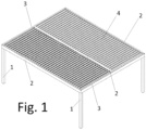
- Figure 1 shows an example of embodiment of the pergola. It starts with a support (1) such as columns, walls, etc. and one or more frames or spans with two or more longitudinal girders (2) and at least one crossbar (3).
- the frame defines a useful surface covered by parallel slats (4).
- the frame is generally rectangular or square, but in fact it will be sufficient for the invention to work if only one of the girders (2) is straight.
- the slats (4) only have to be of variable length to adapt to a pergola with a girder (2) that is not straight.
- the frame will usually be basically horizontal, but this depends on the specific use for which the pergola is intended.
- the slats (4) are fitted with axial shafts (5) parallel to each other and usually equidistant to each other.
- the axial shafts (5) are supported by the girders (2) by means of shims, bearings or any other system that enables freedom of rotation.
- Each axial shaft (5) is connected to a pinion (6) which in turn engages on a motorised rack (7) that can be common to all the slats (4).
- the rack (7) is moved by means of a hydraulic cylinder (8). It is also possible to arrange two or more independent parallel racks (7) so that the pinions (6) engage on one rack or the other (7), thus creating partitions. In this way it is possible to act on a certain number if slats (4); to open all of them or only a sector, open alternate slats (4), etc. This arrangement also enables a reduction in the required power of the motor by permitting the option of placing two or more motors or provide for the sequential opening of the slats (4).
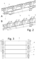
- the pinion (6) can be circular or - to reduce its height - have a minor segment cut along a chord of the circle formed by the wheel, for example, as shown in figure 2 .
- the rack (7) can have teeth along its entire length or only in the area used by each pinion (6).
- the translational motion of the rack (7) results in rotation of the slats (4) in a coordinated manner.
- the cut of the pinion (6) serves, among other functions, to facilitate control of its position during assembly.
- all the slats (4) are parallel if all the cuts are placed in a parallel position. This can also be achieved by making a mark on the wheel - on one of the teeth for example - but this solution is less evident at first glance.
- the system is extremely effective, since the rack's (7) translational motion is not affected by the position of the slats (4). Consequently, the motor can be lighter and less powerful than in the state of the art.
- the components are not especially bulky and can be concealed inside the associated girder (2), thus protecting them from water and dust and removing them from sight. To do so, the motor and rack (7) are placed inside the girder (2) on the opposite side to the associated bearing. This system also requires less maintenance than other similar solutions such as those that use an auger screw, especially if hydraulic cylinders (8) are used to move the racks (7).
- FIG 3 shows a detail of an embodiment in which the slats (4) are grouped into partitions. In this case, they are grouped into even and odd slats (4). All the slats (4) belonging to the same partition move in unison. For achieve this, two racks (7) have been placed, one on each girder (2), and the pinions (6) are fitted on one end axial shaft (5) of the slat (4) or the other.
- the user can activate the hydraulic cylinder of each rack (7) independently to act on the partitions or on all the racks (7) in parallel to move all the slats (7).
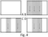
- Figure 4 shows different positions of the slats (4) of a pergola with four partitions.
- Two racks (7) are placed in alternating order on each longitudinal girder (the first on one girder, the second on the other, the third on the first girder, etc).
- All partitions are in the open position in figure A. Therefore, the pergola will not cast a shadow.
- the partition on the right is open and the others are closed.
- the partitions are alternately open or closed.
- the end partitions are open and the central ones are closed. Other combinations are possible.
Landscapes
- Engineering & Computer Science (AREA)
- Architecture (AREA)
- Civil Engineering (AREA)
- Structural Engineering (AREA)
- Housing For Livestock And Birds (AREA)
- Blinds (AREA)
- Nitrogen Condensed Heterocyclic Rings (AREA)
- Transmission Devices (AREA)
Abstract
Description
- This invention consists of a pergola with an improved upper slat support that enables the use of standard parts in the manufacture of various models.
- The existence of pergolas with rotating slats whose inclination is variable to block or allow the passage of light and air currents is known in the state of the art.
ES1285474U WO2019084590A1 provide two examples. These types of system are fitted with complex mechanisms to ensure that the orientation of all the slats is identical. However, complex mechanisms are less reliable and more expensive than the mechanism proposed by this invention. - Certain examples of such a system involve a bar connected to all the slats at an identical distance from their axial shafts. Movement of said bar produces coordinated rotation of the slats. This system requires a hydraulic or pneumatic cylinder and considerable electric power to achieve the movement to or from any angle of the slat and radius of the rotational moment. This in turn gives rise to noise and requires robust components.
- The applicant is not aware of any solution similar to the claimed invention.
- The invention consists of a pergola with rotating slats as set forth in the claims. In several embodiments it solves the problems inherent in the state of the art.
- The pergola is composed of a frame support, the frame formed in turn by two longitudinal girders and one or more crossbars that act as stiffeners. Inside the frame there is a series of parallel rotating slats, each one with an axial shaft, arranged between the two girders. One of the girders is straight and is fitted with a pinion attached to each axial shaft and engaged with one or more motorised racks. All the slats of a frame or span should preferably be operated by the same rack, but they can also be arranged in divisions or partitions.
- A preferred manner of making partitions is to place two or more racks parallel to each other and arrange the pinions of the different slats to engage on one of the two racks. The most highly preferred partition solution is to place the racks at each end of the slats on the two straight girders. Due to the simplicity of the structure, the easiest way to execute it is with a single rack on each girder.
- It must be taken into account that the most common solution is for the two girders to be parallel, but it is possible to use other angles if the racks or pinions are fitted with helical gears.
- If the slats' axial shafts are identical at each end, the question of which slats are associated with each rack can be decided during the design or construction phases, thus enabling them to move in unison to form the partition. Placing the pinions at one or the other end of the slat during assembly will be sufficient. Thus the odd and even slats can be made to move independently of each other, several consecutive slats (for example all those at one end) can move independently of the others and other specific configurations are possible.
- This, for example, enables the operator to modify the ventilation without significantly affecting the solar radiation, to create shaded and sunny areas for different users of the same pergola and other similar advantages.
- Other variations will be indicated throughout this specification.
- The following figures are provided to enhance comprehension of the invention.
-
Figure 1 : Perspective view of an example of a dual-span pergola. -
Figure 2 : Perspective detail of the transmission between pinions and rack in two positions (A) and (B). -
Figure 3 : Top view of an embodiment in which the slats are partitioned. -
Figure 4 : Top view of examples of positions of a pergola with four partitions: A) Open. B) Partition with one open end. C) Alternating partitions and D) Partitions open at both ends. - Below, an embodiment of the invention will be briefly discussed, as an illustrative and not limitative example.
-
Figure 1 shows an example of embodiment of the pergola. It starts with a support (1) such as columns, walls, etc. and one or more frames or spans with two or more longitudinal girders (2) and at least one crossbar (3). The frame defines a useful surface covered by parallel slats (4). The frame is generally rectangular or square, but in fact it will be sufficient for the invention to work if only one of the girders (2) is straight. The slats (4) only have to be of variable length to adapt to a pergola with a girder (2) that is not straight. The frame will usually be basically horizontal, but this depends on the specific use for which the pergola is intended. - The slats (4) are fitted with axial shafts (5) parallel to each other and usually equidistant to each other. The axial shafts (5) are supported by the girders (2) by means of shims, bearings or any other system that enables freedom of rotation.
- Each axial shaft (5) is connected to a pinion (6) which in turn engages on a motorised rack (7) that can be common to all the slats (4). In
figure 2 , the rack (7) is moved by means of a hydraulic cylinder (8). It is also possible to arrange two or more independent parallel racks (7) so that the pinions (6) engage on one rack or the other (7), thus creating partitions. In this way it is possible to act on a certain number if slats (4); to open all of them or only a sector, open alternate slats (4), etc. This arrangement also enables a reduction in the required power of the motor by permitting the option of placing two or more motors or provide for the sequential opening of the slats (4). - The pinion (6) can be circular or - to reduce its height - have a minor segment cut along a chord of the circle formed by the wheel, for example, as shown in
figure 2 . In turn, the rack (7) can have teeth along its entire length or only in the area used by each pinion (6). The translational motion of the rack (7) results in rotation of the slats (4) in a coordinated manner. The cut of the pinion (6) serves, among other functions, to facilitate control of its position during assembly. Thus, it will be known that all the slats (4) are parallel if all the cuts are placed in a parallel position. This can also be achieved by making a mark on the wheel - on one of the teeth for example - but this solution is less evident at first glance. - The system is extremely effective, since the rack's (7) translational motion is not affected by the position of the slats (4). Consequently, the motor can be lighter and less powerful than in the state of the art. In addition, the components are not especially bulky and can be concealed inside the associated girder (2), thus protecting them from water and dust and removing them from sight. To do so, the motor and rack (7) are placed inside the girder (2) on the opposite side to the associated bearing. This system also requires less maintenance than other similar solutions such as those that use an auger screw, especially if hydraulic cylinders (8) are used to move the racks (7).
-
Figure 3 shows a detail of an embodiment in which the slats (4) are grouped into partitions. In this case, they are grouped into even and odd slats (4). All the slats (4) belonging to the same partition move in unison. For achieve this, two racks (7) have been placed, one on each girder (2), and the pinions (6) are fitted on one end axial shaft (5) of the slat (4) or the other. - In use, the user can activate the hydraulic cylinder of each rack (7) independently to act on the partitions or on all the racks (7) in parallel to move all the slats (7).
-
Figure 4 shows different positions of the slats (4) of a pergola with four partitions. Two racks (7) are placed in alternating order on each longitudinal girder (the first on one girder, the second on the other, the third on the first girder, etc). In this embodiment it is possible to align the racks (7) on each side since the slats (4) that they affect are separated and the racks (7) can be separated sufficiently to ensure that they do not to collide. All partitions are in the open position in figure A. Therefore, the pergola will not cast a shadow. In figure B the partition on the right is open and the others are closed. In figure C the partitions are alternately open or closed. In figure D the end partitions are open and the central ones are closed. Other combinations are possible.
Claims (6)
- Pergola with rotating slats, comprised of a support (1) of a frame formed by two or more longitudinal girders (2) and at least one crossbar (3), with at least one of the longitudinal girders (2) being straight, and a series of rotating slats (4) with axial shafts (5) parallel to each other and supported by the girders (2), characterised by the axial shafts (5) ending, on the straight girder (2), on respective pinions (6) engaged on one or more motorised racks (7).
- Pergola with rotating slats according to claim 1, characterised in that the pinions (6) have a minor sector cut off according to a chord of the circle formed by the respective pinion (6).
- Pergola with rotating slats, according to claim 1, characterised in that the rack (7) has teeth only in the area engaged by each pinion (6).
- Pergola with rotating slats, according to claim 1, characterised in that it is comprised of two or more racks (7) and that each slat (4) has a single pinion (6) engaged on one rack (7).
- Pergola with rotating slats, according to claim 4, characterised in that it has two straight girders (2) and each girder (2) is fitted with at least one rack (7).
- Pergola with rotating slats, according to claim 1, characterised in that each rack (7) is moved by a hydraulic cylinder (8).
Applications Claiming Priority (2)
| Application Number | Priority Date | Filing Date | Title |
|---|---|---|---|
| ES202230239A ES2952145A1 (en) | 2022-03-21 | 2022-03-21 | Pergola with rotating slats |
| PCT/ES2023/070176 WO2023180608A1 (en) | 2022-03-21 | 2023-03-20 | Pergola with rotating slats |
Publications (1)
| Publication Number | Publication Date |
|---|---|
| EP4497893A1 true EP4497893A1 (en) | 2025-01-29 |
Family
ID=86226886
Family Applications (1)
| Application Number | Title | Priority Date | Filing Date |
|---|---|---|---|
| EP23719807.2A Pending EP4497893A1 (en) | 2022-03-21 | 2023-03-20 | Pergola with rotating slats |
Country Status (4)
| Country | Link |
|---|---|
| EP (1) | EP4497893A1 (en) |
| ES (1) | ES2952145A1 (en) |
| FR (1) | FR3133632B3 (en) |
| WO (1) | WO2023180608A1 (en) |
Families Citing this family (1)
| Publication number | Priority date | Publication date | Assignee | Title |
|---|---|---|---|---|
| CN118815224B (en) * | 2024-09-18 | 2024-12-17 | 河南速轮轨道交通装备有限公司 | Protective shed for track construction |
Family Cites Families (12)
| Publication number | Priority date | Publication date | Assignee | Title |
|---|---|---|---|---|
| US2857634A (en) * | 1956-02-09 | 1958-10-28 | Garbade | Reversible slat assemblage |
| CH611674A5 (en) * | 1976-12-29 | 1979-06-15 | Posnansky Mario | Means for covering over terraces or workshops |
| JPS5636801U (en) * | 1979-08-31 | 1981-04-08 | ||
| AU548289B2 (en) * | 1982-02-22 | 1985-12-05 | Premier Blinds Pty. Ltd. | Adjustable blind or awning |
| CN2926374Y (en) * | 2006-06-28 | 2007-07-25 | 李毅 | Solar external sunshading board |
| IT1397519B1 (en) * | 2009-12-21 | 2013-01-16 | Franchi | MOBILE SUNSCREEN SHIELDING SYSTEM WITH PERFECT STRUCTURE. |
| CN201605742U (en) * | 2010-05-26 | 2010-10-13 | 苏州科技学院 | An external sunshade device |
| FR3049976B1 (en) * | 2016-04-12 | 2022-08-05 | Biossun | INSTALLATION FOR COVERING AND UNVEILING A SURFACE USING ATTACHED SELF-PROPELLED SWIVEL BLADES |
| ITUA20162879A1 (en) * | 2016-04-26 | 2017-10-26 | Giuseppe Genchi | ROLLED SHUTTERS AND RELATED STATION MOVEMENT SYSTEM |
| ES2969932T3 (en) | 2017-10-30 | 2024-05-23 | Advanced Design Innovations Pty Ltd | Retractable roof/wall assembly |
| CN112854883A (en) * | 2021-03-09 | 2021-05-28 | 台州博旅达工艺品有限公司 | Outdoor louver awning with awning top capable of being combined and expanded |
| ES1285474Y (en) | 2021-12-09 | 2022-04-25 | Escobar Miguel Gonzalez | Adjustable or fixed slats, with thermal bridge break, opaque and transparent, with parallel operation for double thermal, acoustic and safety control of pergolas and homes |
-
2022
- 2022-03-21 ES ES202230239A patent/ES2952145A1/en active Pending
-
2023
- 2023-03-20 EP EP23719807.2A patent/EP4497893A1/en active Pending
- 2023-03-20 FR FR2302567A patent/FR3133632B3/en active Active
- 2023-03-20 WO PCT/ES2023/070176 patent/WO2023180608A1/en not_active Ceased
Also Published As
| Publication number | Publication date |
|---|---|
| FR3133632A3 (en) | 2023-09-22 |
| FR3133632B3 (en) | 2024-03-08 |
| ES2952145A1 (en) | 2023-10-27 |
| WO2023180608A1 (en) | 2023-09-28 |
Similar Documents
| Publication | Publication Date | Title |
|---|---|---|
| JP4800390B2 (en) | Traffic barrier | |
| WO2016001739A1 (en) | Adjustable louvers folding and rotation mechanism able to protect from sun's rays, rain or other atmospheric agents | |
| CA2974479A1 (en) | Wind turbine with rotary guides | |
| DE3836861A1 (en) | SHUT-OFF DEVICE FOR CHANNELS WITH LARGE CROSS-SECTIONS, IN PARTICULAR SMOKE GAS CHANNELS | |
| US2848180A (en) | Airplane wing | |
| DE19517856A1 (en) | Wind-powered wheel for deriving mechanical energy at driven shaft | |
| EP4234392A2 (en) | Transverse propulsion device of a ship | |
| DE10106672B4 (en) | Slitter | |
| DE4020334A1 (en) | ARRANGEMENT FOR SWIVELING SLATELY FITTED, A WALL OR ROOF ELEMENT FORMING PANEL ELEMENTS | |
| WO2023180608A1 (en) | Pergola with rotating slats | |
| DE1628426B2 (en) | FAN | |
| EP3913162B1 (en) | Covering apparatus | |
| KR910008244A (en) | Circulation three-dimensional parking device | |
| AT403734B (en) | ARRANGEMENT OF AXIAL FANS FOR WOOD DRYING PLANTS | |
| EP0442282A2 (en) | Textile machine, in particular twisting machine | |
| EP3913163B1 (en) | Covering apparatus | |
| WO1998026224A1 (en) | Building facade | |
| CN209469087U (en) | Adjustable Multilayer grid | |
| DE4110540A1 (en) | Wind-operated power generator - has profiled axial blades in ring around rotor with convex-curved surfaces leading | |
| DE2919328A1 (en) | Vertical or horizontal axis windmill with several blades - has system of gears and cams controlling angle of attack of blades throughout rotation | |
| DE4437438A1 (en) | Combined wind-driven generator and room ventilator | |
| RU1818448C (en) | Greenhouse ventilation mechanism | |
| CN221415239U (en) | Metal structure cutting equipment | |
| JPH0328152Y2 (en) | ||
| DE272870C (en) |
Legal Events
| Date | Code | Title | Description |
|---|---|---|---|
| STAA | Information on the status of an ep patent application or granted ep patent |
Free format text: STATUS: UNKNOWN |
|
| STAA | Information on the status of an ep patent application or granted ep patent |
Free format text: STATUS: THE INTERNATIONAL PUBLICATION HAS BEEN MADE |
|
| PUAI | Public reference made under article 153(3) epc to a published international application that has entered the european phase |
Free format text: ORIGINAL CODE: 0009012 |
|
| STAA | Information on the status of an ep patent application or granted ep patent |
Free format text: STATUS: REQUEST FOR EXAMINATION WAS MADE |
|
| 17P | Request for examination filed |
Effective date: 20241016 |
|
| AK | Designated contracting states |
Kind code of ref document: A1 Designated state(s): AL AT BE BG CH CY CZ DE DK EE ES FI FR GB GR HR HU IE IS IT LI LT LU LV MC ME MK MT NL NO PL PT RO RS SE SI SK SM TR |
|
| RAV | Requested validation state of the european patent: fee paid |
Extension state: TN Effective date: 20241016 Extension state: MA Effective date: 20241016 |