EP4497702A1 - Packing support member - Google Patents
Packing support member Download PDFInfo
- Publication number
- EP4497702A1 EP4497702A1 EP23774457.8A EP23774457A EP4497702A1 EP 4497702 A1 EP4497702 A1 EP 4497702A1 EP 23774457 A EP23774457 A EP 23774457A EP 4497702 A1 EP4497702 A1 EP 4497702A1
- Authority
- EP
- European Patent Office
- Prior art keywords
- wall
- fold
- reinforcement
- continuous
- support
- Prior art date
- Legal status (The legal status is an assumption and is not a legal conclusion. Google has not performed a legal analysis and makes no representation as to the accuracy of the status listed.)
- Pending
Links
Images




Classifications
-
- B—PERFORMING OPERATIONS; TRANSPORTING
- B65—CONVEYING; PACKING; STORING; HANDLING THIN OR FILAMENTARY MATERIAL
- B65D—CONTAINERS FOR STORAGE OR TRANSPORT OF ARTICLES OR MATERIALS, e.g. BAGS, BARRELS, BOTTLES, BOXES, CANS, CARTONS, CRATES, DRUMS, JARS, TANKS, HOPPERS, FORWARDING CONTAINERS; ACCESSORIES, CLOSURES, OR FITTINGS THEREFOR; PACKAGING ELEMENTS; PACKAGES
- B65D5/00—Rigid or semi-rigid containers of polygonal cross-section, e.g. boxes, cartons or trays, formed by folding or erecting one or more blanks made of paper
- B65D5/42—Details of containers or of foldable or erectable container blanks
- B65D5/44—Integral, inserted or attached portions forming internal or external fittings
- B65D5/50—Internal supporting or protecting elements for contents
- B65D5/5028—Elements formed separately from the container body
- B65D5/5035—Paper elements
- B65D5/5047—Blocks
- B65D5/505—Blocks formed by folding up one or more blanks to form a hollow block
-
- B—PERFORMING OPERATIONS; TRANSPORTING
- B65—CONVEYING; PACKING; STORING; HANDLING THIN OR FILAMENTARY MATERIAL
- B65D—CONTAINERS FOR STORAGE OR TRANSPORT OF ARTICLES OR MATERIALS, e.g. BAGS, BARRELS, BOTTLES, BOXES, CANS, CARTONS, CRATES, DRUMS, JARS, TANKS, HOPPERS, FORWARDING CONTAINERS; ACCESSORIES, CLOSURES, OR FITTINGS THEREFOR; PACKAGING ELEMENTS; PACKAGES
- B65D5/00—Rigid or semi-rigid containers of polygonal cross-section, e.g. boxes, cartons or trays, formed by folding or erecting one or more blanks made of paper
- B65D5/42—Details of containers or of foldable or erectable container blanks
- B65D5/44—Integral, inserted or attached portions forming internal or external fittings
- B65D5/50—Internal supporting or protecting elements for contents
- B65D5/5028—Elements formed separately from the container body
- B65D5/5035—Paper elements
-
- B—PERFORMING OPERATIONS; TRANSPORTING
- B65—CONVEYING; PACKING; STORING; HANDLING THIN OR FILAMENTARY MATERIAL
- B65D—CONTAINERS FOR STORAGE OR TRANSPORT OF ARTICLES OR MATERIALS, e.g. BAGS, BARRELS, BOTTLES, BOXES, CANS, CARTONS, CRATES, DRUMS, JARS, TANKS, HOPPERS, FORWARDING CONTAINERS; ACCESSORIES, CLOSURES, OR FITTINGS THEREFOR; PACKAGING ELEMENTS; PACKAGES
- B65D5/00—Rigid or semi-rigid containers of polygonal cross-section, e.g. boxes, cartons or trays, formed by folding or erecting one or more blanks made of paper
- B65D5/42—Details of containers or of foldable or erectable container blanks
- B65D5/44—Integral, inserted or attached portions forming internal or external fittings
- B65D5/50—Internal supporting or protecting elements for contents
- B65D5/5028—Elements formed separately from the container body
- B65D5/5035—Paper elements
- B65D5/504—Racks having upstanding ridges formed by folds, and provided with slits or recesses
-
- B—PERFORMING OPERATIONS; TRANSPORTING
- B65—CONVEYING; PACKING; STORING; HANDLING THIN OR FILAMENTARY MATERIAL
- B65D—CONTAINERS FOR STORAGE OR TRANSPORT OF ARTICLES OR MATERIALS, e.g. BAGS, BARRELS, BOTTLES, BOXES, CANS, CARTONS, CRATES, DRUMS, JARS, TANKS, HOPPERS, FORWARDING CONTAINERS; ACCESSORIES, CLOSURES, OR FITTINGS THEREFOR; PACKAGING ELEMENTS; PACKAGES
- B65D5/00—Rigid or semi-rigid containers of polygonal cross-section, e.g. boxes, cartons or trays, formed by folding or erecting one or more blanks made of paper
- B65D5/42—Details of containers or of foldable or erectable container blanks
- B65D5/44—Integral, inserted or attached portions forming internal or external fittings
- B65D5/50—Internal supporting or protecting elements for contents
- B65D5/5028—Elements formed separately from the container body
- B65D5/5035—Paper elements
- B65D5/5047—Blocks
- B65D5/5054—Blocks formed by a plurality of layers contacting each other, e.g. multiple layers of corrugated cardboard
- B65D5/5057—Blocks formed by a plurality of layers contacting each other, e.g. multiple layers of corrugated cardboard and provided with slits or recesses in which at least a part of the contents are located
-
- B—PERFORMING OPERATIONS; TRANSPORTING
- B65—CONVEYING; PACKING; STORING; HANDLING THIN OR FILAMENTARY MATERIAL
- B65D—CONTAINERS FOR STORAGE OR TRANSPORT OF ARTICLES OR MATERIALS, e.g. BAGS, BARRELS, BOTTLES, BOXES, CANS, CARTONS, CRATES, DRUMS, JARS, TANKS, HOPPERS, FORWARDING CONTAINERS; ACCESSORIES, CLOSURES, OR FITTINGS THEREFOR; PACKAGING ELEMENTS; PACKAGES
- B65D81/00—Containers, packaging elements, or packages, for contents presenting particular transport or storage problems, or adapted to be used for non-packaging purposes after removal of contents
- B65D81/02—Containers, packaging elements, or packages, for contents presenting particular transport or storage problems, or adapted to be used for non-packaging purposes after removal of contents specially adapted to protect contents from mechanical damage
- B65D81/05—Containers, packaging elements, or packages, for contents presenting particular transport or storage problems, or adapted to be used for non-packaging purposes after removal of contents specially adapted to protect contents from mechanical damage maintaining contents at spaced relation from package walls, or from other contents
-
- B—PERFORMING OPERATIONS; TRANSPORTING
- B65—CONVEYING; PACKING; STORING; HANDLING THIN OR FILAMENTARY MATERIAL
- B65D—CONTAINERS FOR STORAGE OR TRANSPORT OF ARTICLES OR MATERIALS, e.g. BAGS, BARRELS, BOTTLES, BOXES, CANS, CARTONS, CRATES, DRUMS, JARS, TANKS, HOPPERS, FORWARDING CONTAINERS; ACCESSORIES, CLOSURES, OR FITTINGS THEREFOR; PACKAGING ELEMENTS; PACKAGES
- B65D2581/00—Containers, packaging elements, or packages, for contents presenting particular transport or storage problems, or adapted to be used for non-packaging purposes after removal of contents
- B65D2581/02—Containers, packaging elements, or packages, for contents presenting particular transport or storage problems, or adapted to be used for non-packaging purposes after removal of contents specially adapted to protect contents from mechanical damage
- B65D2581/05—Containers, packaging elements, or packages, for contents presenting particular transport or storage problems, or adapted to be used for non-packaging purposes after removal of contents specially adapted to protect contents from mechanical damage maintaining contents at spaced relation from package walls, or from other contents
- B65D2581/051—Details of packaging elements for maintaining contents at spaced relation from package walls, or from other contents
- B65D2581/052—Materials
- B65D2581/053—Paper in general, e.g. paperboard, carton, molded paper
-
- Y—GENERAL TAGGING OF NEW TECHNOLOGICAL DEVELOPMENTS; GENERAL TAGGING OF CROSS-SECTIONAL TECHNOLOGIES SPANNING OVER SEVERAL SECTIONS OF THE IPC; TECHNICAL SUBJECTS COVERED BY FORMER USPC CROSS-REFERENCE ART COLLECTIONS [XRACs] AND DIGESTS
- Y02—TECHNOLOGIES OR APPLICATIONS FOR MITIGATION OR ADAPTATION AGAINST CLIMATE CHANGE
- Y02W—CLIMATE CHANGE MITIGATION TECHNOLOGIES RELATED TO WASTEWATER TREATMENT OR WASTE MANAGEMENT
- Y02W30/00—Technologies for solid waste management
- Y02W30/50—Reuse, recycling or recovery technologies
- Y02W30/80—Packaging reuse or recycling, e.g. of multilayer packaging
Definitions
- the present disclosure relates to a packaging supporter to store and support an item to be packaged such as a photosensitive drum in a box made of, for example, corrugated cardboard.
- Patent Literatures 1 and 2 are described in, for example, Patent Literatures 1 and 2.
- a packaging supporter supports an item to be packaged in a box.
- the packaging supporter includes a support being a rectangular prism and being cushioning.
- the support includes first to seventh walls, and first and second reinforcements.
- the second wall includes a first fold and is continuous with the first wall with the first fold between the second wall and the first wall.
- the third wall includes a second fold and is continuous with the second wall with the second fold between the third wall and the second wall.
- the third wall faces the first wall.
- the fourth wall includes a third fold and is continuous with the third wall with the third fold between the fourth wall and the third wall.
- the fourth wall defines a third recessed corner between the third wall and the fourth wall.
- the fifth wall includes a fourth fold and is continuous with the fourth wall with the fourth fold between the fifth wall and the fourth wall.
- the fifth wall extends along the first wall.
- the sixth wall includes a fifth fold and is continuous with the fifth wall with the fifth fold between the sixth wall and the fifth wall.
- the sixth wall faces the second wall and the fourth wall, defines a first recessed corner between the second wall and the third wall, and defines a second recessed corner between the fifth wall and the sixth wall.
- the seventh wall includes a sixth fold and is continuous with the sixth wall with the sixth fold between the seventh wall and the sixth wall.
- the seventh wall extends along the third wall.
- the first reinforcement is continuous with the first wall and protrudes from the first wall toward the third wall.
- the first reinforcement is supported by the first recessed corner.
- the second reinforcement is continuous with the seventh wall and protrudes from the seventh wall toward the fifth wall.
- the second reinforcement is supported by the second recessed corner.
- Patent Literature 1 describes a cushioning body including a rectangular support tube that is formed by folding a sheet of corrugated cardboard.
- An adhesive plate inside the support tube has a leading edge folded at a fold line to form a bracing plate.
- the bracing plate has a leading edge in contact with an inner corner of the support tube to improve the strength of the support tube.
- Patent Literature 2 describes a receiving cushioning material for packaging including a rectangular prism body that is formed by folding a sheet of corrugated cardboard.
- a middle reinforcement with a length equal to a diagonal line and two side reinforcements separately located on each side of the middle reinforcement are formed inside the rectangular prism body.
- the side reinforcements are folded along a diagonal line to intersect with the diagonal line of the middle reinforcement.
- a leading edge of each of the middle and side reinforcements comes in contact with a corner of a side wall to improve the shape retention, the cushioning ability, and the compression resistance of the receiving cushioning material.
- Patent Literature 1 The structure with a known technique described in Patent Literature 1 includes the single bracing plate extending along one diagonal line of the diagonal lines of a rectangular of the rectangular prism body, and may not reduce deformation under a pressing force applied obliquely from a direction not along the bracing plate. Additionally, the leading edge of the support tube is folded across its length to form the bracing plate. This is likely to increase the dimensions of the corrugated cardboard and the material cost. Further, the bracing plate is formed using the folded portion of the leading edge that is a part of the support tube. This thus restricts the direction and the arrangement of the bracing plate.
- a packaging supporter with high strength without upsizing the structure including known components is thus awaited.
- a packaging supporter according to one or more embodiments of the present disclosure will be described below with reference to the drawings.
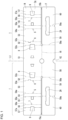
- FIG. 1 is a development view of a packaging supporter according to an embodiment of the present disclosure.
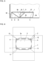
- FIG. 2A is an enlarged perspective view of the packaging supporter, illustrating a portion adjacent to a support.
- FIG. 2B is a perspective view of the packaging supporter with a seventh wall being upright.
- FIG. 2C is a perspective view of the packaging supporter with a sixth wall and the seventh wall both being upright.
- FIG. 2D is a perspective view of the packaging supporter with the support assembled.
- a packaging supporter 1 according to the present embodiment is, in a developed state as illustrated in FIG. 1 , a substantially rectangular base board 1a that is a sheet of punched corrugated cardboard.
- the packaging supporter 1 supports, in a box, a photosensitive drum with a large diameter as an example item to be packaged.
- the packaging supporter 1 includes a pair of supports 4 that are rectangular prisms and serve as cushioning for supporting a photosensitive drum 3 in a box 2 illustrated in FIGs. 6 and 7 (described later).
- Each of the supports 4 includes a first reinforcement 8 and a second reinforcement 9.
- the box 2 is made of, for example, corrugated cardboard.
- the box 2 includes a body that is a rectangular prism, a bottom including four bottom boards each continuous with one of four sides of a first end of the body in its axial direction, and a lid including four upper boards each continuous with one of four sides of a second end of the body in its axial direction.
- the box 2 is a hollow rectangular prism with the bottom and the lid closed with respect to the body during packaging of the item.
- the photosensitive drum 3 includes a drum body 3a that is a right cylinder.
- the packaging supporter 1 including the supports 4 is used together with a pair of body receivers 11 that support the drum body 3a, a pair of insertion holders 12 that receive the body receivers 11, and a pair of covers 13 that cover, from above, the insertion holders 12 and two ends of the photosensitive drum 3 in its axial direction.
- these components are typically separate from one another, some of the components may be parts integrally included in the packaging supporter 1.
- the base board 1a includes a first strip 14 and a second strip 17.
- the first strip 14 is symmetrical with respect to an imaginary plane including a central axis L1 passing through the center of the base board 1a in the longitudinal direction of the base board 1a, and includes, on each side across a single first wall 51, a second wall 52, a third wall 53, a fourth wall 54, a fifth wall 55, a sixth wall 56, and a seventh wall 57.
- the second to seventh walls 52 to 57 on one side and the second to seventh walls 52 to 57 on the other side are located symmetrically to each other in this order with respect to the first wall 51.
- the second strip 17 is continuous with the first wall 51 with an intermediate fold 16 defined by a pair of cutouts 15a and 15b between the second strip 17 and the first wall 51.
- the example illustrated in FIG. 1 includes two portions to be the supports 4 that are located symmetrically to each other across the central axis L1.
- Each of the supports 4 includes the first wall 51, the second wall 52, the third wall 53, the fourth wall 54, the fifth wall 55, the sixth wall 56, and the seventh wall 57.
- the second wall 52 includes a first fold 52a and is continuous with the first wall 51 with the first fold 52a between them.
- the third wall 53 includes a second fold 53a and is continuous with the second wall 52 with the second fold 53a between them.
- the third wall 53 faces the first wall 51.
- the fourth wall 54 includes a third fold 54a and is continuous with the third wall 53 with the third fold 54a between them.
- the fourth wall 54 defines a third recessed corner 5 between the third wall 53 and the fourth wall 54.
- the fifth wall 55 includes a fourth fold 55a and is continuous with the fourth wall 54 with the fourth fold 55a between them.
- the fifth wall 55 extends along the first wall 51.
- the sixth wall 56 includes a fifth fold 56a and is continuous with the fifth wall 55 with the fifth fold 56a between them.
- the sixth wall 56 faces the second wall 52 and the fourth wall 54, and defines a first recessed corner 6 between the first wall 51 and the sixth wall 56 and a second recessed corner 7 between the fifth wall 55 and the sixth wall 56.
- the seventh wall 57 includes a sixth fold 57a and is continuous with the sixth wall 56 with the sixth fold 57a between them.
- the seventh wall 57 extends along the third wall 53.
- the second strip 17 includes a single eighth wall 58, and a ninth wall 59 and a tenth wall 60 on each of both sides across the eighth wall 58.
- the eighth wall 58 includes the intermediate fold 16 and is continuous with the first wall 51 in the first strip 14 with the intermediate fold 16 between them.
- the intermediate fold 16 extends linearly between the cutouts 15a and 15b.
- the eighth wall 58 includes, on each of its two ends in its longitudinal direction, a seventh fold 58a perpendicular to the intermediate fold 16.
- the eighth wall 58 is continuous with the ninth wall 59 with the seventh fold 58a between them.
- the ninth wall 59 includes an eighth fold 59a.
- the ninth wall 59 is continuous with the tenth wall 60 with the eighth fold 59a between them.
- the eighth fold 59a is parallel to the seventh fold 58a.
- the ninth wall 59 has a cutout 29.
- the tenth wall 60 has the cutout 29.
- the cutouts 29 extend symmetrically to each other with respect to the eighth fold 59a.
- the ninth wall 59 and the tenth wall 60 on one side and the ninth wall 59 and the tenth wall 60 on the other side are located symmetrically to each other with respect to the imaginary plane including the central axis L1 described above.
- the first wall 51 and the eighth wall 58 include a through-hole 61 that is circular in the developed state and has its center at the intersection of the intermediate fold 16 and the central axis L1.
- the eighth wall 58 includes, in a side portion opposite to a first side portion including the through-hole 61, a semicircular through-hole 62 having its center at the intersection of an outer periphery and the central axis L1.
- the first reinforcement 8 is continuous with the first wall 51 and protrudes from the first wall 51 toward the third wall 53.
- the first reinforcement 8 stands, along a fold, toward the inside of the support 4 to extend from the first wall 51 toward the second wall 52.
- a leading edge of the first reinforcement 8 then comes in contact with the first recessed corner 6 to support the first recessed corner 6.
- the second reinforcement 9 is continuous with the seventh wall 57 and protrudes from the seventh wall 57 toward the fifth wall 55.
- the second reinforcement 9 stands, along a fold, toward the inside of the support 4 to extend from the seventh wall 57 toward the sixth wall 56.
- the second reinforcement 9 thus stands, inside the support 4, to be inclined in the opposite direction to the first reinforcement 8 across the sixth wall 56.
- a leading edge of the second reinforcement 9 then comes in contact with the second recessed corner 7 to support the second recessed corner 7.
- Each of the first reinforcement 8 and the second reinforcement 9 is trapezoidal in the developed state, with the lower side being longer than the upper side and continuous with the first wall 51 or the seventh wall 57.
- the pressing force is distributed and transmitted to the first wall 51 and the seventh wall 57.
- This increases the strength of the first reinforcement 8 supporting the first recessed corner 6 and reduces the likelihood of the first reinforcement 8 braking or splitting at the lower side continuous with the first wall 51.
- this increases the strength of the second reinforcement 9 supporting the second recessed corner 7 and reduces the likelihood of the second reinforcement 9 breaking or splitting at the lower side continuous with the seventh wall 57.
- the packaging supporter 1 and the support 4 may be made of corrugated cardboard having a machine direction perpendicular to a direction in which the first to seventh walls 51 to 57 are continuous with one another.
- FIG. 3 is a side view of an assembly of a base board including the first to fifth walls 51 to 55.
- FIG. 4 is a side view of an assembly of a base board including the first to seventh walls 51 to 57.
- FIG. 5 is a side view of the support 4 in the embodiment of the present disclosure.
- the impact load from the same or similar dropping is applied on the long sides of the rectangle.
- the assembly is deformed less than the structure in FIG. 3 but may not have a sufficient strength.
- the support 4 in the present embodiment includes the first reinforcement 8 and the second reinforcement 9 to increase the durability against the impact load applied to the long sides of the rectangle.
- the support 4 is deformed less than the assembly of the base board including the first to seventh walls 51 to 57 in FIG. 4 and has a higher strength.
- the packaging supporter 1 including the support 4 thus has high strength for supporting the item and high impact durability.
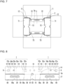
- FIG. 6 is a plan view of the box 2 storing the photosensitive drum 3 together with the packaging supporters 1 including the supports 4, the body receivers 11, and the insertion holders 12.
- FIG. 7 is a plan view of the box 2 storing the photosensitive drum 3 together with the packaging supporters 1 including the supports 4 (hidden under the covers 13), the body receivers 11, and the insertion holders 12, with the covers 13 attached.
- the packaging supporter 1 includes the supports 4 each reinforced with the first reinforcement 8 and the second reinforcement 9.
- the supports 4, which also serve as cushioning, can thus endure the impact load on the photosensitive drum 3 from dropping of the box 2, reducing damage to the photosensitive drum 3 that is a packaged item.
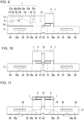
- FIGs. 8 to 12 are diagrams describing a procedure for assembling the packaging supporter 1.
- a first support 4 on the right in the figure is assembled first to be a rectangular prism by sequentially folding a first end portion (right end portion) of the first strip 14 in the longitudinal direction inward at each of the folds 57a, 56a, 55a, 54a, 53a, and 52a for valley fold.
- a second support 4 is assembled to be a rectangular prism by sequentially folding a second end portion (left end portion) of the first strip 14 in the longitudinal direction inward at each of the folds 57a, 56a, 55a, 54a, 53a, and 52a for valley fold.
- the first wall 51 is folded at about 90° to be upright on the second strip 17 together with the two supports 4 as illustrated in FIG. 10 , and the second strip 17 is then folded inward from its two ends, with the eighth fold 59a mountain-folded and the seventh fold 58a valley-folded on each side as illustrated in FIG. 11 .
- the pair of insertion holders 12 folded into an inverted-V shape are thus assembled.
- FIGs. 13 to 16 are diagrams describing a procedure for assembling the body receiver 11.
- the body receiver 11 is a substantially rectangular base board 1b made of corrugated cardboard.
- the body receiver 11 includes a through-hole 18 located on the left in FIG. 13 and having an inner diameter substantially the same as the outer diameter of the drum body 3a to allow the drum body 3a to be fitted in the through-hole 18.
- the body receiver 11 also includes a through-hole 19 located on the right with respect to the through-hole 18 in FIG. 13 and having a substantially semicircular shape that is symmetrical to the left half of the through-hole 18.
- the base board 1b is defined to include four sections referred to as, in this order from the left in the figure, a first portion 21, a second portion 22, a third portion 23, and a fourth portion 24, in the longitudinal direction of the base board 1b.
- the first portion 21 includes a first fold 21a at a position at which the first fold 21a divides the through-hole 18 equally between the first portion 21 and the second portion 22.
- the second portion 22 includes a second fold 22a between the second portion 22 and the third portion 23.
- the third portion 23 includes a third fold 23a between the third portion 23 and the fourth portion 24.
- the first portion 21, the second portion 22, the third portion 23, and the fourth portion 24 have the same width in a horizontal direction in FIG. 13 .
- the first to fourth portions 21 to 24 include the respective cutouts 25a and 25b, 26a and 26b, 27a and 27b, and 28a and 28b at positions adjacent to the two ends of the respective first to fourth portions 21 to 24 in a width direction perpendicular to the longitudinal direction of the base board 1b.
- the body receiver 11 including the through-holes 18 and 19 that are semicircular and overlap each other is formed as illustrated in FIG. 16 .
- two body receivers 11 with the above structure are used when the single photosensitive drum 3 is packaged in the single box 2.
- FIG. 17 is a diagram describing a procedure for attaching the body receiver 11 to the insertion holders 12.
- FIG. 18 is a diagram of the body receiver 11 held by the insertion holders 12. With the first to fourth portions 21 to 24 overlapping one another as illustrated in FIG. 16 , the cutouts 25a to 28a and the cutouts 25b to 28b in the body receiver 11 also overlap one another and are open in a first direction (leftward in FIG. 16 ).
- the body receiver 11 is inserted into the insertion holders 12 through the cutout 29 of each of the insertion holders 12 to cause the cutouts 25a to 28a and 25b to 28b to be meshed with the corresponding cutout 29.
- This combination of components stably support the photosensitive drum 3 in the box 2.
- the covers 13 each include a ceiling plate 71 that is substantially rectangular as viewed in plan to cover, from above, the two ends of the photosensitive drum 3 in the axial direction, and a pair of side plates 72 and 73 that are folded at substantially right angles to be continuous with the respective ends of the ceiling plate 71 in the longitudinal direction of the ceiling plate 71.
- Each of the side plates 72 and 73 includes a cutout in which the body receiver 11 is fitted.
- the body receiver 11 fitted in each of the cutout in the side plates 72 and 73 reduces the displacement of the covers 13 with respect to the body receiver 11, allowing the two ends of the photosensitive drum 3 in the axial direction to be covered with the ceiling plates 71 and reducing damage to the photosensitive drum 3 caused by vibrations or other factors in the box 2.
- the single support 4 includes the single first reinforcement 8 and the single second reinforcement 9. In another embodiment of the present disclosure, however, the single support 4 may include multiple (e.g., two or more) first reinforcements 8 and second reinforcements 9 in the width direction. This further increases the compression strength and allows the packaging supporter to have higher durability against the impact load.
- the multiple first reinforcements 8 and the multiple second reinforcements 9 may be arranged to have multiple pairs of the first reinforcement 8 and the second reinforcement 9 facing each other, or to alternate the first reinforcements 8 and the second reinforcements 9.
- the multiple pairs of the first reinforcement 8 and the second reinforcement 9 may each have any width and may be arranged at any intervals between the pairs.
- the widths and the intervals may be set as appropriate for the packaging specifications.
- the first reinforcements 8 and the second reinforcements 9 arranged alternately may each have any width and may be arranged at any intervals between them.
- the widths and the intervals may be set as appropriate for the packaging specifications.
- one second reinforcement 9 may be located between two first reinforcements 8, one first reinforcement 8 may be located between two second reinforcements 9, the same numbers of first reinforcements 8 and second reinforcements 9 may be located alternately one by one, or the multiple first reinforcements 8 and the multiple second reinforcements 9 may be located alternately. In either case, the widths of the reinforcements and the intervals between them may be set as appropriate.
- the oblique sides of the first reinforcement 8 and the second reinforcement 9 may each have any angles, and may be set as appropriate for the packaging specifications. For example, the oblique sides may all have the same angle, or may have different angles appropriate for the positions.
- the packaging supporter may be made of, instead of the corrugated cardboard described above, a material with appropriate elasticity and flexibility such as general-purpose plastic including soft polyvinyl chloride, polyethylene, and polypropylene, or a sheet made of foamed plastic or processed paper.
- general-purpose plastic including soft polyvinyl chloride, polyethylene, and polypropylene, or a sheet made of foamed plastic or processed paper.
- the first reinforcement 8 is formed in areas in the first wall 51 and the second wall 52
- the second reinforcement 9 is formed in areas in the sixth wall 56 and the seventh wall 57.
- the first reinforcement 8 and the second reinforcement 9 can thus be formed without increasing the use of materials such as corrugated cardboard, and can improve the load strength without bonding. This increases the durability of the support 4 against the impact load, allowing the packaging supporter 1 to have high strength against the impact load without upsizing the structure of the packaging supporter 1.
- the packaging supporter 1 can thus reduce damage to the item and protect the item with larger dimensions and higher mass, as with a photosensitive drum having a large diameter, and receives a large external force such as a shock load from falling or collapsing during transportation.
- the packaging supporter 1 can also be used to support many relatively small items such as photosensitive drums with small diameters that are to be packaged collectively.
- the item as an example in the present embodiment is a photosensitive drum.
- the item may be any object to be packaged such as various industrial or consumer devices, or various mechanical or electronic components.
- the packaging supporter includes the support with high strength without upsizing the structure.
- the packaging supporter may have may have aspects (1) to (6) described below.
Landscapes
- Engineering & Computer Science (AREA)
- Mechanical Engineering (AREA)
- Buffer Packaging (AREA)
Abstract
Description
- The present disclosure relates to a packaging supporter to store and support an item to be packaged such as a photosensitive drum in a box made of, for example, corrugated cardboard.
- Known packaging supporters are described in, for example,
Patent Literatures -
- Patent Literature 1:
Japanese Unexamined Patent Application Publication No. 6-293362 - Patent Literature 2:
Japanese Unexamined Patent Application Publication No. 9-104476 - In an aspect of the present disclosure, a packaging supporter supports an item to be packaged in a box. The packaging supporter includes a support being a rectangular prism and being cushioning. The support includes first to seventh walls, and first and second reinforcements. The second wall includes a first fold and is continuous with the first wall with the first fold between the second wall and the first wall. The third wall includes a second fold and is continuous with the second wall with the second fold between the third wall and the second wall. The third wall faces the first wall. The fourth wall includes a third fold and is continuous with the third wall with the third fold between the fourth wall and the third wall. The fourth wall defines a third recessed corner between the third wall and the fourth wall. The fifth wall includes a fourth fold and is continuous with the fourth wall with the fourth fold between the fifth wall and the fourth wall. The fifth wall extends along the first wall. The sixth wall includes a fifth fold and is continuous with the fifth wall with the fifth fold between the sixth wall and the fifth wall. The sixth wall faces the second wall and the fourth wall, defines a first recessed corner between the second wall and the third wall, and defines a second recessed corner between the fifth wall and the sixth wall. The seventh wall includes a sixth fold and is continuous with the sixth wall with the sixth fold between the seventh wall and the sixth wall. The seventh wall extends along the third wall. The first reinforcement is continuous with the first wall and protrudes from the first wall toward the third wall. The first reinforcement is supported by the first recessed corner. The second reinforcement is continuous with the seventh wall and protrudes from the seventh wall toward the fifth wall. The second reinforcement is supported by the second recessed corner.
-
-
FIG. 1 is a development view of a packaging supporter according to an embodiment of the present disclosure. -
FIG. 2A is an enlarged perspective view of the packaging supporter, illustrating a portion adjacent to a support. -
FIG. 2B is a perspective view of the packaging supporter with a seventh wall being upright. -
FIG. 2C is a perspective view of the packaging supporter with a sixth wall and the seventh wall both being upright. -
FIG. 2D is a perspective view of the packaging supporter with the support assembled. -
FIG. 3 is a side view of an assembly of a base board including first to fifth walls. -
FIG. 4 is a side view of an assembly of a base board including first to seventh walls. -
FIG. 5 is a side view of the support according to the embodiment of the present disclosure. -
FIG. 6 is a plan view of a box storing a photosensitive drum together with the packaging supporters including the supports, body receivers, and insertion holders. -
FIG. 7 is a plan view of the box storing the photosensitive drum together with the packaging supporters including the supports, the body receivers, and the insertion holders, with covers attached. -
FIG. 8 is a diagram describing a procedure for assembling the packaging supporter. -
FIG. 9 is a diagram describing the procedure for assembling the packaging supporter. -
FIG. 10 is a diagram describing the procedure for assembling the packaging supporter. -
FIG. 11 is a diagram describing the procedure for assembling the packaging supporter. -
FIG. 12 is a diagram describing the procedure for assembling the packaging supporter. -
FIG. 13 is a diagram describing a procedure for assembling the body receiver. -
FIG. 14 is a diagram describing the procedure for assembling the body receiver. -
FIG. 15 is a diagram describing the procedure for assembling the body receiver. -
FIG. 16 is a diagram describing the procedure for assembling the body receiver. -
FIG. 17 is a diagram describing a procedure for attaching the body receiver to the insertion holders. -
FIG. 18 is a diagram of the body receiver held by the insertion holders. -
Patent Literature 1 describes a cushioning body including a rectangular support tube that is formed by folding a sheet of corrugated cardboard. An adhesive plate inside the support tube has a leading edge folded at a fold line to form a bracing plate. The bracing plate has a leading edge in contact with an inner corner of the support tube to improve the strength of the support tube. -
Patent Literature 2 describes a receiving cushioning material for packaging including a rectangular prism body that is formed by folding a sheet of corrugated cardboard. A middle reinforcement with a length equal to a diagonal line and two side reinforcements separately located on each side of the middle reinforcement are formed inside the rectangular prism body. The side reinforcements are folded along a diagonal line to intersect with the diagonal line of the middle reinforcement. A leading edge of each of the middle and side reinforcements comes in contact with a corner of a side wall to improve the shape retention, the cushioning ability, and the compression resistance of the receiving cushioning material. - The structure with a known technique described in
Patent Literature 1 includes the single bracing plate extending along one diagonal line of the diagonal lines of a rectangular of the rectangular prism body, and may not reduce deformation under a pressing force applied obliquely from a direction not along the bracing plate. Additionally, the leading edge of the support tube is folded across its length to form the bracing plate. This is likely to increase the dimensions of the corrugated cardboard and the material cost. Further, the bracing plate is formed using the folded portion of the leading edge that is a part of the support tube. This thus restricts the direction and the arrangement of the bracing plate. - In the structure with a known technique described in
Patent Literature 2, two side portions of the leading edge of the rectangular prism are folded inward to serve as the reinforcements and form bracing plates, and the middle portion of the leading edge is cut midway and folded inward to be orthogonal to the two side reinforcements as the middle reinforcement. This is likely to increase the dimensions of the corrugated cardboard and increase the manufacturing cost and the material cost as compared with a normal rectangular support tube. - A packaging supporter with high strength without upsizing the structure including known components is thus awaited.
- A packaging supporter according to one or more embodiments of the present disclosure will be described below with reference to the drawings.
-
FIG. 1 is a development view of a packaging supporter according to an embodiment of the present disclosure.FIG. 2A is an enlarged perspective view of the packaging supporter, illustrating a portion adjacent to a support.FIG. 2B is a perspective view of the packaging supporter with a seventh wall being upright.FIG. 2C is a perspective view of the packaging supporter with a sixth wall and the seventh wall both being upright.FIG. 2D is a perspective view of the packaging supporter with the support assembled. Apackaging supporter 1 according to the present embodiment is, in a developed state as illustrated inFIG. 1 , a substantiallyrectangular base board 1a that is a sheet of punched corrugated cardboard. When the corrugated cardboard is a wavy board with a paper liner attached to each of its two sides in a thickness direction of the corrugated cardboard, the wavy board is oriented to have its machine direction that is a direction of repeated recesses and protrusions of the wavy core board perpendicular to a longitudinal direction of thebase board 1a. In the present embodiment, thepackaging supporter 1 supports, in a box, a photosensitive drum with a large diameter as an example item to be packaged. - The
packaging supporter 1 includes a pair ofsupports 4 that are rectangular prisms and serve as cushioning for supporting aphotosensitive drum 3 in abox 2 illustrated inFIGs. 6 and7 (described later). Each of thesupports 4 includes afirst reinforcement 8 and asecond reinforcement 9. Thebox 2 is made of, for example, corrugated cardboard. Thebox 2 includes a body that is a rectangular prism, a bottom including four bottom boards each continuous with one of four sides of a first end of the body in its axial direction, and a lid including four upper boards each continuous with one of four sides of a second end of the body in its axial direction. Thebox 2 is a hollow rectangular prism with the bottom and the lid closed with respect to the body during packaging of the item. - The
photosensitive drum 3 includes adrum body 3a that is a right cylinder. To support thephotosensitive drum 3 in thebox 2, in an example illustrated inFIGs. 6 and7 , thepackaging supporter 1 including thesupports 4 is used together with a pair ofbody receivers 11 that support thedrum body 3a, a pair ofinsertion holders 12 that receive thebody receivers 11, and a pair ofcovers 13 that cover, from above, theinsertion holders 12 and two ends of thephotosensitive drum 3 in its axial direction. Although these components are typically separate from one another, some of the components may be parts integrally included in thepackaging supporter 1. - The
base board 1a includes afirst strip 14 and asecond strip 17. Thefirst strip 14 is symmetrical with respect to an imaginary plane including a central axis L1 passing through the center of thebase board 1a in the longitudinal direction of thebase board 1a, and includes, on each side across a singlefirst wall 51, asecond wall 52, athird wall 53, afourth wall 54, afifth wall 55, asixth wall 56, and aseventh wall 57. The second toseventh walls 52 to 57 on one side and the second toseventh walls 52 to 57 on the other side are located symmetrically to each other in this order with respect to thefirst wall 51. Thesecond strip 17 is continuous with thefirst wall 51 with anintermediate fold 16 defined by a pair ofcutouts second strip 17 and thefirst wall 51. - The example illustrated in
FIG. 1 includes two portions to be thesupports 4 that are located symmetrically to each other across the central axis L1. Each of thesupports 4 includes thefirst wall 51, thesecond wall 52, thethird wall 53, thefourth wall 54, thefifth wall 55, thesixth wall 56, and theseventh wall 57. Thesecond wall 52 includes afirst fold 52a and is continuous with thefirst wall 51 with thefirst fold 52a between them. Thethird wall 53 includes asecond fold 53a and is continuous with thesecond wall 52 with thesecond fold 53a between them. Thethird wall 53 faces thefirst wall 51. Thefourth wall 54 includes athird fold 54a and is continuous with thethird wall 53 with thethird fold 54a between them. Thefourth wall 54 defines a third recessedcorner 5 between thethird wall 53 and thefourth wall 54. Thefifth wall 55 includes afourth fold 55a and is continuous with thefourth wall 54 with thefourth fold 55a between them. Thefifth wall 55 extends along thefirst wall 51. Thesixth wall 56 includes afifth fold 56a and is continuous with thefifth wall 55 with thefifth fold 56a between them. Thesixth wall 56 faces thesecond wall 52 and thefourth wall 54, and defines a first recessedcorner 6 between thefirst wall 51 and thesixth wall 56 and a second recessedcorner 7 between thefifth wall 55 and thesixth wall 56. Theseventh wall 57 includes asixth fold 57a and is continuous with thesixth wall 56 with thesixth fold 57a between them. Theseventh wall 57 extends along thethird wall 53. - The
second strip 17 includes a singleeighth wall 58, and aninth wall 59 and atenth wall 60 on each of both sides across theeighth wall 58. Theeighth wall 58 includes theintermediate fold 16 and is continuous with thefirst wall 51 in thefirst strip 14 with theintermediate fold 16 between them. Theintermediate fold 16 extends linearly between thecutouts eighth wall 58 includes, on each of its two ends in its longitudinal direction, aseventh fold 58a perpendicular to theintermediate fold 16. Theeighth wall 58 is continuous with theninth wall 59 with theseventh fold 58a between them. Theninth wall 59 includes aneighth fold 59a. Theninth wall 59 is continuous with thetenth wall 60 with theeighth fold 59a between them. Theeighth fold 59a is parallel to theseventh fold 58a. Theninth wall 59 has acutout 29. Thetenth wall 60 has thecutout 29. Thecutouts 29 extend symmetrically to each other with respect to theeighth fold 59a. Theninth wall 59 and thetenth wall 60 on one side and theninth wall 59 and thetenth wall 60 on the other side are located symmetrically to each other with respect to the imaginary plane including the central axis L1 described above. - The
first wall 51 and theeighth wall 58 include a through-hole 61 that is circular in the developed state and has its center at the intersection of theintermediate fold 16 and the central axis L1. Theeighth wall 58 includes, in a side portion opposite to a first side portion including the through-hole 61, a semicircular through-hole 62 having its center at the intersection of an outer periphery and the central axis L1. - The
first reinforcement 8 is continuous with thefirst wall 51 and protrudes from thefirst wall 51 toward thethird wall 53. When thesupport 4 is assembled, thefirst reinforcement 8 stands, along a fold, toward the inside of thesupport 4 to extend from thefirst wall 51 toward thesecond wall 52. A leading edge of thefirst reinforcement 8 then comes in contact with the first recessedcorner 6 to support the first recessedcorner 6. Thesecond reinforcement 9 is continuous with theseventh wall 57 and protrudes from theseventh wall 57 toward thefifth wall 55. When thesupport 4 is assembled, thesecond reinforcement 9 stands, along a fold, toward the inside of thesupport 4 to extend from theseventh wall 57 toward thesixth wall 56. Thesecond reinforcement 9 thus stands, inside thesupport 4, to be inclined in the opposite direction to thefirst reinforcement 8 across thesixth wall 56. A leading edge of thesecond reinforcement 9 then comes in contact with the second recessedcorner 7 to support the second recessedcorner 7. Each of thefirst reinforcement 8 and thesecond reinforcement 9 is trapezoidal in the developed state, with the lower side being longer than the upper side and continuous with thefirst wall 51 or theseventh wall 57. Thus, when a pressing force applied on the upper side reaches the lower side, the pressing force is distributed and transmitted to thefirst wall 51 and theseventh wall 57. This increases the strength of thefirst reinforcement 8 supporting the first recessedcorner 6 and reduces the likelihood of thefirst reinforcement 8 braking or splitting at the lower side continuous with thefirst wall 51. In the same or in a similar manner, this increases the strength of thesecond reinforcement 9 supporting the second recessedcorner 7 and reduces the likelihood of thesecond reinforcement 9 breaking or splitting at the lower side continuous with theseventh wall 57. - The
packaging supporter 1 and thesupport 4 may be made of corrugated cardboard having a machine direction perpendicular to a direction in which the first toseventh walls 51 to 57 are continuous with one another. -
FIG. 3 is a side view of an assembly of a base board including the first tofifth walls 51 to 55.FIG. 4 is a side view of an assembly of a base board including the first toseventh walls 51 to 57.FIG. 5 is a side view of thesupport 4 in the embodiment of the present disclosure. For the base board including the first tofifth walls 51 to 55 folded into the assembly that is a rectangular prism with a cross section of a rectangle, an impact load from dropping of thebox 2 storing thephotosensitive drum 3 is applied on the long sides of the rectangle. This deforms the assembly receiving the load into a rhombus as illustrated inFIG. 3 . The assembly may not have a sufficient strength. For the base board including the first toseventh walls 51 to 57 folded into the assembly that is a rectangular prism with a cross section of a rectangle, the impact load from the same or similar dropping is applied on the long sides of the rectangle. This deforms the assembly receiving the load into a rhombus as illustrated inFIG. 4 . The assembly is deformed less than the structure inFIG. 3 but may not have a sufficient strength. In contrast, thesupport 4 in the present embodiment includes thefirst reinforcement 8 and thesecond reinforcement 9 to increase the durability against the impact load applied to the long sides of the rectangle. Thesupport 4 is deformed less than the assembly of the base board including the first toseventh walls 51 to 57 inFIG. 4 and has a higher strength. Thepackaging supporter 1 including thesupport 4 thus has high strength for supporting the item and high impact durability. -
FIG. 6 is a plan view of thebox 2 storing thephotosensitive drum 3 together with thepackaging supporters 1 including thesupports 4, thebody receivers 11, and theinsertion holders 12.FIG. 7 is a plan view of thebox 2 storing thephotosensitive drum 3 together with thepackaging supporters 1 including the supports 4 (hidden under the covers 13), thebody receivers 11, and theinsertion holders 12, with thecovers 13 attached. As described above, thepackaging supporter 1 according to the present embodiment includes thesupports 4 each reinforced with thefirst reinforcement 8 and thesecond reinforcement 9. Thesupports 4, which also serve as cushioning, can thus endure the impact load on thephotosensitive drum 3 from dropping of thebox 2, reducing damage to thephotosensitive drum 3 that is a packaged item. -
FIGs. 8 to 12 are diagrams describing a procedure for assembling thepackaging supporter 1. In assembling thepackaging supporter 1, as illustrated inFIG. 8 , afirst support 4 on the right in the figure is assembled first to be a rectangular prism by sequentially folding a first end portion (right end portion) of thefirst strip 14 in the longitudinal direction inward at each of thefolds - Subsequently, as illustrated in
FIG. 9 , asecond support 4 is assembled to be a rectangular prism by sequentially folding a second end portion (left end portion) of thefirst strip 14 in the longitudinal direction inward at each of thefolds supports 4 are assembled together, thefirst wall 51 is folded at about 90° to be upright on thesecond strip 17 together with the twosupports 4 as illustrated inFIG. 10 , and thesecond strip 17 is then folded inward from its two ends, with theeighth fold 59a mountain-folded and theseventh fold 58a valley-folded on each side as illustrated inFIG. 11 . As illustrated inFIG. 12 , the pair ofinsertion holders 12 folded into an inverted-V shape are thus assembled. -
FIGs. 13 to 16 are diagrams describing a procedure for assembling thebody receiver 11. Thebody receiver 11 is a substantiallyrectangular base board 1b made of corrugated cardboard. Thebody receiver 11 includes a through-hole 18 located on the left inFIG. 13 and having an inner diameter substantially the same as the outer diameter of thedrum body 3a to allow thedrum body 3a to be fitted in the through-hole 18. Thebody receiver 11 also includes a through-hole 19 located on the right with respect to the through-hole 18 inFIG. 13 and having a substantially semicircular shape that is symmetrical to the left half of the through-hole 18. Thebase board 1b is defined to include four sections referred to as, in this order from the left in the figure, afirst portion 21, asecond portion 22, athird portion 23, and afourth portion 24, in the longitudinal direction of thebase board 1b. Thefirst portion 21 includes afirst fold 21a at a position at which thefirst fold 21a divides the through-hole 18 equally between thefirst portion 21 and thesecond portion 22. Thesecond portion 22 includes asecond fold 22a between thesecond portion 22 and thethird portion 23. Thethird portion 23 includes athird fold 23a between thethird portion 23 and thefourth portion 24. Thefirst portion 21, thesecond portion 22, thethird portion 23, and thefourth portion 24 have the same width in a horizontal direction inFIG. 13 . - When the
first portion 21 is folded inward at thefirst fold 21a for valley fold to overlap thesecond portion 22, a half of the through-hole 18 overlaps the other half of the through-hole 18 to have a semicircular shape as illustrated inFIG. 14 . Then, when thefourth portion 24 is folded inward at thethird fold 23a for valley fold to overlap thethird portion 23, a part of thethird portion 23 located below is partially exposed through the semicircular through-hole 19 in thefourth portion 24 as illustrated inFIG. 15 . The first tofourth portions 21 to 24 include therespective cutouts fourth portions 21 to 24 in a width direction perpendicular to the longitudinal direction of thebase board 1b. - Subsequently, when the
first portion 21 and thesecond portion 22 are folded inward at thesecond fold 22a for valley fold to overlap thefourth portion 24, thebody receiver 11 including the through-holes FIG. 16 . To support the two ends of thedrum body 3a with thefirst portion 21, thesecond portion 22, and a part of thefourth portion 24 exposed through each of the through-holes body receivers 11 with the above structure are used when the singlephotosensitive drum 3 is packaged in thesingle box 2. -
FIG. 17 is a diagram describing a procedure for attaching thebody receiver 11 to theinsertion holders 12.FIG. 18 is a diagram of thebody receiver 11 held by theinsertion holders 12. With the first tofourth portions 21 to 24 overlapping one another as illustrated inFIG. 16 , thecutouts 25a to 28a and thecutouts 25b to 28b in thebody receiver 11 also overlap one another and are open in a first direction (leftward inFIG. 16 ). Thebody receiver 11 is inserted into theinsertion holders 12 through thecutout 29 of each of theinsertion holders 12 to cause thecutouts 25a to 28a and 25b to 28b to be meshed with the correspondingcutout 29. This reduces displacement of thebody receiver 11 and stably holds thebody receiver 11 at a predetermined position with respect to theinsertion holders 12 in thepackaging supporter 1. This combination of components stably support thephotosensitive drum 3 in thebox 2. - As illustrated in
FIG. 7 described above, thecovers 13 each include aceiling plate 71 that is substantially rectangular as viewed in plan to cover, from above, the two ends of thephotosensitive drum 3 in the axial direction, and a pair ofside plates ceiling plate 71 in the longitudinal direction of theceiling plate 71. Each of theside plates body receiver 11 is fitted. Thebody receiver 11 fitted in each of the cutout in theside plates covers 13 with respect to thebody receiver 11, allowing the two ends of thephotosensitive drum 3 in the axial direction to be covered with theceiling plates 71 and reducing damage to thephotosensitive drum 3 caused by vibrations or other factors in thebox 2. - In the above embodiment, the
single support 4 includes the singlefirst reinforcement 8 and the singlesecond reinforcement 9. In another embodiment of the present disclosure, however, thesingle support 4 may include multiple (e.g., two or more)first reinforcements 8 andsecond reinforcements 9 in the width direction. This further increases the compression strength and allows the packaging supporter to have higher durability against the impact load. - The multiple
first reinforcements 8 and the multiplesecond reinforcements 9 may be arranged to have multiple pairs of thefirst reinforcement 8 and thesecond reinforcement 9 facing each other, or to alternate thefirst reinforcements 8 and thesecond reinforcements 9. The multiple pairs of thefirst reinforcement 8 and thesecond reinforcement 9 may each have any width and may be arranged at any intervals between the pairs. The widths and the intervals may be set as appropriate for the packaging specifications. Thefirst reinforcements 8 and thesecond reinforcements 9 arranged alternately may each have any width and may be arranged at any intervals between them. The widths and the intervals may be set as appropriate for the packaging specifications. For example, as appropriate for the packaging specifications, onesecond reinforcement 9 may be located between twofirst reinforcements 8, onefirst reinforcement 8 may be located between twosecond reinforcements 9, the same numbers offirst reinforcements 8 andsecond reinforcements 9 may be located alternately one by one, or the multiplefirst reinforcements 8 and the multiplesecond reinforcements 9 may be located alternately. In either case, the widths of the reinforcements and the intervals between them may be set as appropriate. When thefirst reinforcement 8 and thesecond reinforcement 9 are trapezoidal, the oblique sides of thefirst reinforcement 8 and thesecond reinforcement 9 may each have any angles, and may be set as appropriate for the packaging specifications. For example, the oblique sides may all have the same angle, or may have different angles appropriate for the positions. - In still another embodiment of the present disclosure, the packaging supporter may be made of, instead of the corrugated cardboard described above, a material with appropriate elasticity and flexibility such as general-purpose plastic including soft polyvinyl chloride, polyethylene, and polypropylene, or a sheet made of foamed plastic or processed paper.
- In the present embodiment, as described above, the
first reinforcement 8 is formed in areas in thefirst wall 51 and thesecond wall 52, and thesecond reinforcement 9 is formed in areas in thesixth wall 56 and theseventh wall 57. Thefirst reinforcement 8 and thesecond reinforcement 9 can thus be formed without increasing the use of materials such as corrugated cardboard, and can improve the load strength without bonding. This increases the durability of thesupport 4 against the impact load, allowing thepackaging supporter 1 to have high strength against the impact load without upsizing the structure of thepackaging supporter 1. Thepackaging supporter 1 can thus reduce damage to the item and protect the item with larger dimensions and higher mass, as with a photosensitive drum having a large diameter, and receives a large external force such as a shock load from falling or collapsing during transportation. Thepackaging supporter 1 can also be used to support many relatively small items such as photosensitive drums with small diameters that are to be packaged collectively. The item as an example in the present embodiment is a photosensitive drum. However, the item may be any object to be packaged such as various industrial or consumer devices, or various mechanical or electronic components. - The packaging supporter according to one or more embodiments of the present disclosure includes the support with high strength without upsizing the structure.
- The packaging supporter according to one or more embodiments of the present disclosure may have may have aspects (1) to (6) described below.
- (1) A packaging supporter for supporting an item to be packaged in a box, the packaging supporter comprising:
- a support being a rectangular prism and being cushioning,
- wherein the support includes
- a first wall,
- a second wall including a first fold and being continuous with the first wall with the first fold between the second wall and the first wall,
- a third wall including a second fold and being continuous with the second wall with the second fold between the third wall and the second wall, the third wall facing the first wall,
- a fourth wall including a third fold and being continuous with the third wall with the third fold between the fourth wall and the third wall, the fourth wall defining a third recessed corner between the third wall and the fourth wall,
- a fifth wall including a fourth fold and being continuous with the fourth wall with the fourth fold between the fifth wall and the fourth wall, the fifth wall extending along the first wall,
- a sixth wall including a fifth fold and being continuous with the fifth wall with the fifth fold between the sixth wall and the fifth wall, the sixth wall facing the second wall and the fourth wall, defining a first recessed corner between the second wall and the third wall, and defining a second recessed corner between the fifth wall and the sixth wall,
- a seventh wall including a sixth fold and being continuous with the sixth wall with the sixth fold between the seventh wall and the sixth wall, the seventh wall extending along the third wall,
- a first reinforcement being continuous with the first wall and protruding from the first wall toward the third wall, the first reinforcement being supported by the first recessed corner, and
- a second reinforcement being continuous with the seventh wall and protruding from the seventh wall toward the fifth wall, the second reinforcement being supported by the second recessed corner.
- (2) The packaging supporter according to (1), wherein the seventh wall is supported by the third recessed corner.
- (3) The packaging supporter according to (1) or (2), wherein the first reinforcement is trapezoidal in a developed state.
- (4) The packaging supporter according to any one of (1) to (3), wherein the second reinforcement is trapezoidal in a developed state.
- (5) The packaging supporter according to any one of (1) to (4), wherein
the support further includes one or more first reinforcements or one or more second reinforcements located in an axial direction of the support, or the support further includes one or more first reinforcements and one or more second reinforcements located in the axial direction of the support. - (6) The packaging supporter according to any one of (1) to (5), wherein
the packaging supporter comprises corrugated cardboard having a machine direction perpendicular to a direction in which the first wall to the seventh wall are continuous with one another. - Although embodiments of the present disclosure have been described in detail, the present disclosure is not limited to the embodiments, and may be changed or varied in various manners without departing from the spirit and scope of the present disclosure. The components described in the above embodiments may be entirely or partially combined as appropriate unless any contradiction arises.
-
- 1 packaging supporter
- 1a, 1b base board
- 2 box
- 3 photosensitive drum (item)
- 4 support
- 5 third recessed corner
- 6 first recessed corner
- 7 second recessed corner
- 8 first reinforcement
- 9 second reinforcement
- 18, 19 through-hole
- 21 first portion
- 22 second portion
- 23 third portion
- 24 fourth portion
- 51 first wall
- 52 second wall
- 52a first fold
- 53 third wall
- 53a second fold
- 54 fourth wall
- 54a third fold
- 55 fifth wall
- 55a fourth fold
- 56 sixth wall
- 56a fifth fold
- 57 seventh wall
- 57a sixth fold
- 58 eighth wall
- 58a seventh fold
- 59 ninth wall
- 59a eighth fold
- 60 tenth wall
Claims (6)
- A packaging supporter for supporting an item to be packaged in a box, the packaging supporter comprising:a support being a rectangular prism and being cushioning,wherein the support includesa first wall,a second wall including a first fold and being continuous with the first wall with the first fold between the second wall and the first wall,a third wall including a second fold and being continuous with the second wall with the second fold between the third wall and the second wall, the third wall facing the first wall,a fourth wall including a third fold and being continuous with the third wall with the third fold between the fourth wall and the third wall, the fourth wall defining a third recessed corner between the third wall and the fourth wall,a fifth wall including a fourth fold and being continuous with the fourth wall with the fourth fold between the fifth wall and the fourth wall, the fifth wall extending along the first wall,a sixth wall including a fifth fold and being continuous with the fifth wall with the fifth fold between the sixth wall and the fifth wall, the sixth wall facing the second wall and the fourth wall, defining a first recessed corner between the second wall and the third wall, and defining a second recessed corner between the fifth wall and the sixth wall,a seventh wall including a sixth fold and being continuous with the sixth wall with the sixth fold between the seventh wall and the sixth wall, the seventh wall extending along the third wall,a first reinforcement being continuous with the first wall and protruding from the first wall toward the third wall, the first reinforcement being supported by the first recessed corner, anda second reinforcement being continuous with the seventh wall and protruding from the seventh wall toward the fifth wall, the second reinforcement being supported by the second recessed corner.
- The packaging supporter according to claim 1, wherein
the seventh wall is supported by the third recessed corner. - The packaging supporter according to claim 1 or claim 2, wherein
the first reinforcement is trapezoidal in a developed state. - The packaging supporter according to any one of claims 1 to 3, wherein
the second reinforcement is trapezoidal in a developed state. - The packaging supporter according to any one of claims 1 to 4, wherein
the support further includes one or more first reinforcements or one or more second reinforcements located in an axial direction of the support, or the support further includes one or more first reinforcements and one or more second reinforcements located in the axial direction of the support. - The packaging supporter according to any one of claims 1 to 5, wherein
the packaging supporter comprises corrugated cardboard having a machine direction perpendicular to a direction in which the first wall to the seventh wall are continuous with one another.
Applications Claiming Priority (2)
| Application Number | Priority Date | Filing Date | Title |
|---|---|---|---|
| JP2022047346 | 2022-03-23 | ||
| PCT/JP2023/008108 WO2023181858A1 (en) | 2022-03-23 | 2023-03-03 | Packing support member |
Publications (2)
| Publication Number | Publication Date |
|---|---|
| EP4497702A1 true EP4497702A1 (en) | 2025-01-29 |
| EP4497702A4 EP4497702A4 (en) | 2026-03-18 |
Family
ID=87106581
Family Applications (1)
| Application Number | Title | Priority Date | Filing Date |
|---|---|---|---|
| EP23774457.8A Pending EP4497702A4 (en) | 2022-03-23 | 2023-03-03 | PACKAGING CARRIER ELEMENT |
Country Status (3)
| Country | Link |
|---|---|
| US (1) | US20250187809A1 (en) |
| EP (1) | EP4497702A4 (en) |
| JP (1) | JP7309102B1 (en) |
Family Cites Families (56)
| Publication number | Priority date | Publication date | Assignee | Title |
|---|---|---|---|---|
| US1900820A (en) * | 1931-07-24 | 1933-03-07 | F & N Lawn Mower Company | Shipping container |
| US2609136A (en) * | 1947-09-19 | 1952-09-02 | Container Corp | Packing element |
| US2744622A (en) * | 1954-03-25 | 1956-05-08 | George C Sparks | Combination box and cradle for decorated easter eggs and the like |
| US2846064A (en) * | 1956-06-06 | 1958-08-05 | Bonafide Mills Inc | Tile shipping package |
| US2827219A (en) * | 1956-10-04 | 1958-03-18 | George C Sparks | Container insert |
| US2941709A (en) * | 1957-05-06 | 1960-06-21 | Westinghouse Electric Corp | Shipping container |
| US3465877A (en) * | 1968-03-01 | 1969-09-09 | Hoerner Waldorf Corp | Glass packing pad |
| US4027794A (en) * | 1976-02-17 | 1977-06-07 | Packaging Corporation Of America | Shipping container |
| US4134497A (en) * | 1977-08-10 | 1979-01-16 | Fidelity Container Corp. | Shock absorbing carton insert |
| FR2469361A1 (en) * | 1979-11-08 | 1981-05-22 | Paillet Bernard | PACKAGING FOR PHARMACEUTICAL AND SIMILAR BULBS |
| US4792043A (en) * | 1988-02-01 | 1988-12-20 | Packaging Corporation Of America | Shipping unit for non-riding lawn mower or the like |
| US5226542A (en) * | 1990-06-18 | 1993-07-13 | Ade, Inc. | Suspension package |
| US5056665A (en) * | 1990-06-18 | 1991-10-15 | Ade, Inc. | Suspension package |
| US5263612A (en) * | 1992-05-07 | 1993-11-23 | Packaging Corporation Of America | Fibreboard container for fresh produce |
| FR2706863A1 (en) * | 1993-06-25 | 1994-12-30 | Kaysersberg Packaging Sa | Panel for supporting objects |
| US5341934A (en) * | 1993-08-31 | 1994-08-30 | Chicony Electronics Co., Ltd. | Shock-absorbing, compression-protective packing device for cartons |
| JP2579895Y2 (en) * | 1993-11-25 | 1998-09-03 | 松阪段ボール工業株式会社 | Prefabricated cushioning material for packing |
| JP2512901Y2 (en) * | 1993-11-27 | 1996-10-02 | 松阪段ボール工業株式会社 | Assembled cushioning material for packing |
| JP3653322B2 (en) * | 1995-10-09 | 2005-05-25 | 日本紙工業株式会社 | Receiving cushioning material for packaging |
| US5782354A (en) * | 1997-06-09 | 1998-07-21 | Dell Computer Corporation | Corrugated end cap for electrical products |
| US5894932A (en) * | 1997-06-12 | 1999-04-20 | Ade, Inc. | Suspension package |
| US5988389A (en) * | 1998-02-25 | 1999-11-23 | The Mead Corporation | Article cradle |
| US6685025B1 (en) * | 2001-08-02 | 2004-02-03 | Fidelity Container Corporation | Cartridge insert which fits into a box |
| US7021024B2 (en) * | 2001-08-02 | 2006-04-04 | Fidelity Container Corporation | Cartridge insert which fits into a box |
| US7278249B2 (en) * | 2001-08-02 | 2007-10-09 | Fidelity Container Corporation | Insert for receiving and protecting a product and a method of forming the insert |
| US20030178338A1 (en) * | 2002-03-22 | 2003-09-25 | Gayle Vore | Packaging insert |
| US20060110573A1 (en) * | 2004-11-19 | 2006-05-25 | Cheng-Szu Peng | Paperboard padding |
| US7648031B2 (en) * | 2004-12-16 | 2010-01-19 | International Paper Company | Insert for protecting a product within a box |
| US8235216B2 (en) * | 2006-12-05 | 2012-08-07 | Clearpak, Llc | Suspension packaging assembly |
| US8230997B1 (en) * | 2007-11-02 | 2012-07-31 | Mcwilliams Glenn P | Bottle support for packaging and shipping |
| JP5031655B2 (en) * | 2008-04-28 | 2012-09-19 | レンゴー株式会社 | Spacer |
| US8714357B2 (en) * | 2010-04-06 | 2014-05-06 | Sealed Air Corporation (Us) | Packaging system |
| JP5707838B2 (en) * | 2010-10-08 | 2015-04-30 | 富士ゼロックス株式会社 | Packing box |
| US8763803B2 (en) * | 2011-07-07 | 2014-07-01 | Kohler Co. | Packaging for plumbing fixtures |
| US20130199954A1 (en) * | 2012-02-03 | 2013-08-08 | Arthur Rheal Huard | Modular packaging system for fragile planiform materials |
| US9238517B2 (en) * | 2012-09-25 | 2016-01-19 | Pratt Corrugated Holdings, Inc. | Method of packaging a fragile item |
| WO2014165381A1 (en) * | 2013-04-02 | 2014-10-09 | Sealed Air Corporation (Us) | Suspension packaging assembly |
| EP3212526B1 (en) * | 2014-10-31 | 2019-03-27 | Sealed Air Corporation (US) | Retention frame for a packaging assembly |
| MX2017012033A (en) * | 2015-03-25 | 2018-02-19 | Int Paper Co | Shipping and display container with supporting insert. |
| US20160101923A1 (en) * | 2015-10-12 | 2016-04-14 | Thatbox Design, Llc | Suspension pack box designs, blanks and methods |
| CA2964207C (en) * | 2016-04-14 | 2023-01-31 | All Packaging Company | Locking packaging container |
| US10947022B2 (en) * | 2017-03-30 | 2021-03-16 | Kimberly-Clark Worldwide, Inc. | Integrated carton and shipping container design and filling manufacture process |
| US10633140B1 (en) * | 2017-04-21 | 2020-04-28 | Surpack s.a. | Boxes, blanks and associated methods |
| WO2019018229A1 (en) * | 2017-07-21 | 2019-01-24 | Sealed Air Corporation (Us) | Retention packaging assembly |
| US11111051B2 (en) * | 2017-07-25 | 2021-09-07 | Sip Better Inc | Bottle packaging system |
| US10913567B2 (en) * | 2018-07-17 | 2021-02-09 | International Paper Company | Shipping insert and blank for forming same |
| US11214424B2 (en) * | 2019-10-24 | 2022-01-04 | Joyson Safety Systems Acquisition Llc | Packaging system and container |
| US11505390B2 (en) * | 2019-12-02 | 2022-11-22 | Amazon Technologies, Inc. | Impact dampening package |
| US11530084B1 (en) * | 2020-01-13 | 2022-12-20 | Packaging Corporation Of America | Product insert and shipper |
| US11518605B1 (en) * | 2020-05-11 | 2022-12-06 | Moulded Fibre Technologies, Inc. | Packaging unit |
| CN114144360A (en) * | 2020-06-04 | 2022-03-04 | 斯特德凯辛有限公司 | Folding tamper-resistant box and method therefor |
| US11820562B2 (en) * | 2020-09-14 | 2023-11-21 | Apple Inc. | Resilient cardboard cushioning for packaging |
| IT202100008003A1 (en) * | 2021-03-31 | 2022-10-01 | Nakuru S R L | IMPROVED PACKAGING SYSTEM. |
| JP2024033992A (en) * | 2022-08-31 | 2024-03-13 | 王子ホールディングス株式会社 | Cushioning material |
| US20250083888A1 (en) * | 2023-09-11 | 2025-03-13 | Pac 360 Design, Inc. | Packaging system |
| JP2025171298A (en) * | 2024-05-09 | 2025-11-20 | 京セラドキュメントソリューションズ株式会社 | Packaging materials |
-
2023
- 2023-03-03 JP JP2023531703A patent/JP7309102B1/en active Active
- 2023-03-03 EP EP23774457.8A patent/EP4497702A4/en active Pending
- 2023-03-03 US US18/846,272 patent/US20250187809A1/en active Pending
Also Published As
| Publication number | Publication date |
|---|---|
| US20250187809A1 (en) | 2025-06-12 |
| EP4497702A4 (en) | 2026-03-18 |
| JP7309102B1 (en) | 2023-07-14 |
| JPWO2023181858A1 (en) | 2023-09-28 |
Similar Documents
| Publication | Publication Date | Title |
|---|---|---|
| US5156901A (en) | Corrugated cardboard structure | |
| JP2016034852A (en) | Packaging material | |
| WO2023181858A1 (en) | Packing support member | |
| CN112623425B (en) | Package and cushioning member | |
| EP4497702A1 (en) | Packing support member | |
| JP4375192B2 (en) | Packing equipment | |
| JP4452250B2 (en) | Cushioning material | |
| JP2023110985A (en) | Cushioning material and packing body | |
| JP5633975B2 (en) | Packing material | |
| JP4563345B2 (en) | Corner cushioning material and packing equipment | |
| JP3716083B2 (en) | Corrugated cushioning material | |
| JP2018034874A (en) | Packing cushioning material | |
| JP7365657B2 (en) | Double side wall assembly box | |
| JP7535963B2 (en) | Cushioning material | |
| JP3239711B2 (en) | Partition box for packaging box | |
| JP4337536B2 (en) | Packing equipment | |
| JP4813114B2 (en) | Corrugated cushioning material | |
| JP6119486B2 (en) | Packing cushioning material | |
| JP5172581B2 (en) | Corrugated cushioning material and packaging material | |
| JPH0924933A (en) | Box body made of paper material | |
| JP4276011B2 (en) | Packaging materials and packaging structure | |
| JP5016386B2 (en) | Packaging material for rectangular frame and related parts | |
| JP5077387B2 (en) | Packing equipment | |
| JPH092453A (en) | Packaging equipment for outdoor units of separate air conditioners | |
| JP2006062667A (en) | Packing member |
Legal Events
| Date | Code | Title | Description |
|---|---|---|---|
| STAA | Information on the status of an ep patent application or granted ep patent |
Free format text: STATUS: THE INTERNATIONAL PUBLICATION HAS BEEN MADE |
|
| PUAI | Public reference made under article 153(3) epc to a published international application that has entered the european phase |
Free format text: ORIGINAL CODE: 0009012 |
|
| STAA | Information on the status of an ep patent application or granted ep patent |
Free format text: STATUS: REQUEST FOR EXAMINATION WAS MADE |
|
| 17P | Request for examination filed |
Effective date: 20240905 |
|
| AK | Designated contracting states |
Kind code of ref document: A1 Designated state(s): AL AT BE BG CH CY CZ DE DK EE ES FI FR GB GR HR HU IE IS IT LI LT LU LV MC ME MK MT NL NO PL PT RO RS SE SI SK SM TR |
|
| DAV | Request for validation of the european patent (deleted) | ||
| DAX | Request for extension of the european patent (deleted) | ||
| A4 | Supplementary search report drawn up and despatched |
Effective date: 20260212 |
|
| RIC1 | Information provided on ipc code assigned before grant |
Ipc: B65D 81/02 20060101AFI20260206BHEP Ipc: B65D 81/05 20060101ALI20260206BHEP Ipc: B65D 5/50 20060101ALI20260206BHEP |