EP4497701A1 - Protection assembly to receive ends of submarine line sections, related flat rack and method - Google Patents
Protection assembly to receive ends of submarine line sections, related flat rack and method Download PDFInfo
- Publication number
- EP4497701A1 EP4497701A1 EP23306282.7A EP23306282A EP4497701A1 EP 4497701 A1 EP4497701 A1 EP 4497701A1 EP 23306282 A EP23306282 A EP 23306282A EP 4497701 A1 EP4497701 A1 EP 4497701A1
- Authority
- EP
- European Patent Office
- Prior art keywords
- submarine line
- protection assembly
- line sections
- flat rack
- end wall
- Prior art date
- Legal status (The legal status is an assumption and is not a legal conclusion. Google has not performed a legal analysis and makes no representation as to the accuracy of the status listed.)
- Granted
Links
Images



Classifications
-
- B—PERFORMING OPERATIONS; TRANSPORTING
- B65—CONVEYING; PACKING; STORING; HANDLING THIN OR FILAMENTARY MATERIAL
- B65D—CONTAINERS FOR STORAGE OR TRANSPORT OF ARTICLES OR MATERIALS, e.g. BAGS, BARRELS, BOTTLES, BOXES, CANS, CARTONS, CRATES, DRUMS, JARS, TANKS, HOPPERS, FORWARDING CONTAINERS; ACCESSORIES, CLOSURES, OR FITTINGS THEREFOR; PACKAGING ELEMENTS; PACKAGES
- B65D59/00—Plugs, sleeves, caps, or like rigid or semi-rigid elements for protecting parts of articles or for bundling articles, e.g. protectors for screw-threads, end caps for tubes or for bundling rod-shaped articles
-
- B—PERFORMING OPERATIONS; TRANSPORTING
- B60—VEHICLES IN GENERAL
- B60P—VEHICLES ADAPTED FOR LOAD TRANSPORTATION OR TO TRANSPORT, TO CARRY, OR TO COMPRISE SPECIAL LOADS OR OBJECTS
- B60P3/00—Vehicles adapted to transport, to carry or to comprise special loads or objects
- B60P3/40—Vehicles adapted to transport, to carry or to comprise special loads or objects for carrying long loads, e.g. with separate wheeled load supporting elements
-
- B—PERFORMING OPERATIONS; TRANSPORTING
- B65—CONVEYING; PACKING; STORING; HANDLING THIN OR FILAMENTARY MATERIAL
- B65D—CONTAINERS FOR STORAGE OR TRANSPORT OF ARTICLES OR MATERIALS, e.g. BAGS, BARRELS, BOTTLES, BOXES, CANS, CARTONS, CRATES, DRUMS, JARS, TANKS, HOPPERS, FORWARDING CONTAINERS; ACCESSORIES, CLOSURES, OR FITTINGS THEREFOR; PACKAGING ELEMENTS; PACKAGES
- B65D85/00—Containers, packaging elements or packages, specially adapted for particular articles or materials
- B65D85/20—Containers, packaging elements or packages, specially adapted for particular articles or materials for incompressible or rigid rod-shaped or tubular articles
-
- B—PERFORMING OPERATIONS; TRANSPORTING
- B65—CONVEYING; PACKING; STORING; HANDLING THIN OR FILAMENTARY MATERIAL
- B65D—CONTAINERS FOR STORAGE OR TRANSPORT OF ARTICLES OR MATERIALS, e.g. BAGS, BARRELS, BOTTLES, BOXES, CANS, CARTONS, CRATES, DRUMS, JARS, TANKS, HOPPERS, FORWARDING CONTAINERS; ACCESSORIES, CLOSURES, OR FITTINGS THEREFOR; PACKAGING ELEMENTS; PACKAGES
- B65D88/00—Large containers
- B65D88/02—Large containers rigid
- B65D88/12—Large containers rigid specially adapted for transport
- B65D88/129—Transporter frames for containers
Definitions
- the present invention concerns a protection assembly to receive ends of submarine line sections, the protection assembly being intended to be placed on a flat rack or to be part of a flat rack, the protection assembly comprising a horizontal base which extends out along a longitudinal axis.
- the submarine line is for example a flexible line, in particular a flexible pipe, a flexible cable or a flexible umbilical.
- the submarine line is a rigid metallic line, such as a pipe-in-pipe (PiP), a mechanically lined pipe (MLP), or a polymer lined pipe (PLP).
- the submarine line is in particular part of an offshore fluid production, fluid injection site, drilling site communication site, and/or power production site to be decommissioned.
- An offshore production or/and injection site generally comprises fluid collection equipment located at the bottom of a body of water. Numerous fluid injection and/or production lines extend from the fluid collection equipment to the surface, to transport fluids to be injected in the ground below the bottom of the body of water and/or to collect fluids produced from the ground.
- the lines are disconnected or cut from the fluid collection equipment.
- the submarine lines are then lifted with a line recovery system mounted on an offshore vessel.
- the terms "vessel”, “offshore vessel” or “recovery vessel” are identical and they can be used randomly to mean that it refers to a vessel floating on a body of water and equipped with a lay system to lay submarine lines on the floor of the body of water. The lay system is also able to recover the submarine lines resting on the floor of the body of water.
- the submarine lines are retrieved using vessels and are sometimes stored on the deck of the vessel, or onto reels or carousels installed on the deck of the vessel.
- the submarine lines are cut into short sections.
- the submarine line sections in this case have a length ranging from 10 m to 20 m.
- the submarine line sections can then be processed offshore on the vessel or onshore at a deconstruction site.
- the recovered submarine lines often comprise pipes which have been used to carry fluids for long periods of times.
- a production pipe generally conveys not only production fluids such as oil and gas, but also materials from the reservoirs in which the production fluids are extracted.
- the materials comprise Naturally Occurring Radioactive Materials (NORM) and/or other materials.
- NEM Naturally Occurring Radioactive Materials
- the radionuclides are thus transported along the production or injection lines during operation. Consequently, as time elapses, materials such as scales, deposits, sand or sludge accumulate inside or on the inner layers of the production or injection lines. These accumulated materials usually contain non-negligible levels of radionuclides.
- the submarine line also contains liquids, either remains of production liquids which have been transported in the line or water which is present in the line at the end of the recovery process.
- liquids and solids must remain confined within the submarine line sections and should not leak out.
- One aim of the invention is thus to provide an appropriate structure to store and transport submarine line sections recovered from offshore installations, which allows a safe, cost effective and easy handling of the submarine line sections, without risk of leakage of fluids and solids out of the structure and more preferably out of the line section ends.
- the subject matter of the invention is a protection assembly as defined above, characterized in that the protection assembly comprises, a vertically protruding transverse end wall at an end of the horizontal base and two vertically protruding side walls extending from the transverse end wall along sides of the horizontal base, the transverse end wall and the side walls delimiting a storage volume to receive the ends of the submarine line section, the storage volume emerging upwardly via an upper insertion passage, the protection assembly comprising at least a flexible cover movable between a retracted submarine line section loading configuration, at least partially retracted away from the upper insertion passage to allow insertion in the storage volume of ends of submarine line sections through the upper insertion passage and a deployed configuration in the storage volume to cover the ends of the submarine line sections.
- the protection assembly according to the invention may comprise one or more of the following feature(s), taken solely, or according to any technical feasible combination:
- the invention also concerns a flat rack, to receive submarine line sections, the flat rack comprising a horizontal tray extending along a longitudinal axis, and at least one protection assembly as defined above, located at an end of the horizontal tray, preferably two protection assemblies as defined above, located at opposed ends of the horizontal tray.
- the flat rack according to the invention may comprise one or more of the following feature(s), taken solely, or according to any technical feasible combination:
- the invention also concerns a method to store and transport submarine line sections comprising:
- the method according to the invention may comprise one or more of the following feature(s), taken solely, or according to any technical feasible combination:
- a flat rack 6, equipped with protection assemblies 8 according to the invention to receive ends of submarine line sections 12 is shown in figure 2 .
- the flat rack 6 is intended to be used in an offshore recovery installation 10 depicted in figure 1 , to recover a submarine line 11 and to process it in several submarine line sections 12.
- the recovery installation 10 is intended to be operated over a body of water 14 to recover the submarine line 11 in the body of water 14.
- the body of water 14 is for example a sea, an ocean, a lake, and/or a river, its depth is comprised generally between 10 m and 3000 m.
- the submarine line sections 12 are for example sections of flexible pipe, in particular built according with the standards API 17J (Specification for Unbonded Flexible Pipe, 4th edition - May 2014 ) and API RP 17B (Recommended Practice for Flexible Pipe, 5th edition - May 2014 ) established by the American Petroleum Institute.
- the submarine line 11 is advantageously an unbonded flexible pipe. At least two adjacent layers of the flexible pipe are free to move longitudinally with respect to each other during flexure of the pipe.
- each submarine line section 12 has an axis and delimits a central passage for circulation of a fluid, advantageously a petroleum fluid.
- the central passage diameter advantageously ranges from 15 cm to 60 cm.
- the submarine line sections 12 are sections of a Hybrid Flexible Pipe (HFP), in particular built according with the standards DNVGL-ST-F119 (Thermoplastic Composite Pipes, Edition September 2019 ) established by the DNV (Det Norske Veritas GL).
- the hybrid flexible pipe is advantageously an unbonded pipe. At least two adjacent layers of the hybrid flexible pipe are free to move longitudinally with respect to each other during flexure of the pipe.
- the submarine line sections 12 are produced from another type of flexible pipe, such as a bonded flexible pipe, designed, manufactured and used according with the standards API RP 17B (Recommended Practice for Flexible Pipe, 5th edition - March 2014 ), API 7K (Drilling and Well Servicing Equipment, 6th edition - December 2015 ), API 16C (Choke and Kill Equipment, 3rd edition - March 2021 ) and API 17K (Specification for Bonded Flexible Pipe, 3rd edition - August 2017 ) established by the American Petroleum Institute.
- API RP 17B Recommended Practice for Flexible Pipe, 5th edition - March 2014
- API 7K Drilling and Well Servicing Equipment, 6th edition - December 2015
- API 16C Chooke and Kill Equipment, 3rd edition - March 2021
- API 17K Specificification for Bonded Flexible Pipe, 3rd edition - August 2017
- the submarine line sections 12 are produced from an umbilical, as defined in ISO 13628-5 "Petroleum and natural gas industries - Design and operation of subsea production systems - Part 5: Subsea umbilicals" published in December 2009 by the International Organization for Standardization , API 17E "Specification for Subsea Umbilicals", 5th Edition - July 2017 , established by the American Petroleum Institute, and IEC60183:2015, January 2015, IEC60840:2020, May 2020 and/or IEC63026:2019, December 2019 , established by the International Electrotechnical Commission (IEC), all provide standards for the design and manufacture of umbilicals and power cables.
- ISO 13628-5 “Petroleum and natural gas industries - Design and operation of subsea production systems - Part 5: Subsea umbilicals” published in December 2009 by the International Organization for Standardization , API 17E "Specification for Subsea Umbilicals", 5th Edition - July 2017 , established by the American Petroleum Institute, and I
- the submarine line sections are produced from single rigid metallic pipe including for example mechanically lined pipe (MLP) or polymer lined pipe (PLP), or from rigid metallic pipe-in-pipe (PiP), as defined in the offshore standard DNVGL-ST-F101 "Submarine Pipeline Systems", August 2021, established by the DNV (Det Norske Veritas GL ).
- MLP mechanically lined pipe
- PLA polymer lined pipe
- SiP rigid metallic pipe-in-pipe
- the submarine line sections 12 are obtained by successively transversely cutting the submarine line 11 into the submarine line sections 12.
- Each submarine line section 12 has a length advantageously comprised between 10 m and 20 m.
- the submarine line sections 12 are transported in flat racks 6 equipped with protection assemblies 8 from their offshore recovery site to an onshore decommissioning facility where they are deconstructed and their materials recycled.
- the recovery installation 10 comprises a recovery vessel 20, a line recovery system 22 and a processing stage 24, to process an upper end region 26 of the submarine line 11 recovered with the line recovery system 22 into several submarine line sections 12.
- the line recovery system 22 and the processing stage 24 are here carried by the recovery vessel 20
- the recovery installation 10 further comprises, downstream of the processing stage 24, a handling and storage stage 28 comprising at least a flat rack 6 equipped with protection assemblies 8 to carry and store the submarine line sections 12 processed in the processing stage 24.
- the recovery vessel 20 is a ship floating on the surface of the body of water.
- the recovery vessel 20 is a platform, in particular a floating platform.
- the recovery vessel 20 has a hull 30, floating on the surface of the body of water 14 and at least a deck 32 onto which the line recovery system 22, the processing stage 24, and the storage stage 28 are positioned.
- the hull 30 has a moon pool 34 extending vertically through the deck 32 and through the hull 30 to provide a central vertical access in the body of water 14.
- recovery operations can take place over the side or at the back of the vessel 20.
- the line recovery system 22 is configured to vertically or horizontally lift the line above the surface of the body of water 14 to bring the upper end region 26 of the submarine line 11 above the deck 32 to the processing stage 24.
- the submarine line 11 may be lifted via a tiltable or tilted line recovery system 22 (i.e. not completely vertical and not completely horizontal) above the surface of the body of water 14.
- a tiltable or tilted line recovery system 22 i.e. not completely vertical and not completely horizontal
- the said system being inclined over the side, at the middle or at the back of the vessel 20.
- said tiltable systems are actually horizontal lay systems which are slightly inclined of a few degrees, for example between 10° and 45°, in relation to the deck 32 level of the recovery vessel 20.
- the line recovery system 22 is a vertical lift system (VLS) configured to continuously lift a vertical section of the submarine line 11 and to redirect it above the hull 30.
- VLS vertical lift system
- the vertical lifting system 22 is configured to recover the submarine line 11 in a notably J shape configuration.
- the line recovery system 22 comprises another type of lifting system able to carry out a recovery in a S-lay or J-lay configuration.
- the vertical lifting system 22 comprises a tower 36 mounted on the deck 32, and tensioners 38 carried by the tower 36 to continuously lift the submarine line 11.
- the line recovery system 22 further advantageously comprises a redirecting mechanism 40 to bend the submarine line 11 at the top of the tower 36 and redirect it towards the deck 32.
- the tower 36 is here mounted above the moon pool 34.
- the moon pool 34 is typically arranged through the hull 30 of the recovery vessel 20, at the middle/center.
- the tower 36 is advantageously mounted near a side of the hull 30 to lift the submarine line 11 from the side.
- the processing stage 24 here comprises at least a dividing system 44 positioned transversely with regards to the submarine line 11 being divided.
- each dividing system 44 is a line cutter, configured to transversely cut the submarine line 11 substantially perpendicularly to its axis.
- the handling and storage stage 28 comprises a storage area 50 of the deck 32, and at least a crane 52, to carry the submarine line sections 12 to the storage area 130.
- the flat racks 6 equipped with protection assemblies 8 are positioned in the storage area 50 with an alignment transverse to the axis in which they are lay in the processing stage 24.
- the crane 52 is equipped with a deployable lifting crane wire 53 with at least a sling 54 mounted at its free end.
- the or each sling 54 is configured to be tied around several submarine line sections 12 stored in the processing stage 24 to jointly lift all the submarine line sections 12 from the processing stage 24 and lower them into the flat rack 6, as it will be described below.
- the flat rack 6 comprises a horizontal tray 60 extending along a longitudinal axis A-A', and two protection assemblies 8 positioned facing each other at the longitudinal ends of the horizontal tray 60.
- the protection assemblies 8 are separate assemblies placed and potentially fixed at the ends of the horizontal tray 60.
- at least one protection assembly 8 is an integral part of the flat rack 6 positioned at the end of the flat rack 6.
- the flat rack 6 comprises two end transverse vertical plates 64, protruding from the longitudinal ends of the horizontal tray 60.
- the end transverse vertical plates 64 are equipped with at least a lifting point (not shown) to allow lifting of each protection assembly 8.
- the flat rack 6 further comprises lower supporting blocks 66A, 66B to support the submarine line sections 12, extending transversely on the horizontal tray 60 between the protection assemblies 8.
- the flat rack 6 advantageously comprises side stanchions 68 protruding from the sides of the horizontal tray 60 in the intermediate space defined longitudinally between the protection assemblies 8.
- the horizontal tray 60 generally has a length greater than the length of the submarine line sections 12.
- the length of the horizontal tray 60, taken between the longitudinal edges 70 of the tray is generally comprised between 15 m and 25 m.
- the width of the horizontal tray 60 is smaller than its length. It is generally comprised between 5 m and 15 m.
- the horizontal tray 60 dimensions are preferably chosen such that it is configured to be lifted and fixed on a trailer 72 of a truck 74 shown in figure 7 .
- the horizontal tray 60 may be lifted and fixed on another vehicle such as a train, or on a barge or other vessels, in place of a truck 74.
- the flat rack 6 containing submarine line sections 12 can thus be easily lifted from the handling and storage area 50, to a trailer 72 onshore, to be transported towards an onshore submarine line section processing installation.
- each protection assembly 8 is fitted at a longitudinal end of the horizontal tray 60 along a transverse edge 70 of the horizontal tray 60.
- the protection assemblies 8 are laid on the horizontal tray 60, in contact with the transverse vertical plate 64.
- each protection assembly 8 comprises a horizontal base 80, applied on the upper surface of the horizontal tray 60, a transverse end wall 82, protruding from a transverse end edge of the horizontal base 80 and two side walls 84, each extending between a respective side edge 86 of the transverse end wall 82 to a respective lateral edge 88 of the horizontal base 80.
- the transverse end wall 82 and the side walls 84 define a storage volume 89 to receive the ends of submarine line sections 12 positioned on the horizontal tray 60.
- the side walls 84 may also be equipped with lifting point to allow lifting of each protection assembly 8.
- Each protection assembly 8 further comprises a transverse lower wall 90 connecting the free ends of the side walls 84 longitudinally apart from the transverse end wall 82.
- the transverse lower wall 90 defines, with the side walls 84 and the transverse end wall 82, a lower retention basin 92 to collect liquids and solids from ends of the submarine line sections 12.
- the protection assembly 8 further comprises baffles 94 protruding in the retention basin 92.
- the lower retention basin 92 can be advantageously provided with an opening fitted with a tap or plug (not shown) configured to be open from a closed rest configuration to drain the content of the basin 92 at the appropriate time and location.
- a tap or plug (not shown) configured to be open from a closed rest configuration to drain the content of the basin 92 at the appropriate time and location.
- Such an opening or a similar opening put closely can be also used as a monitoring point for detecting hazardous contaminants inside the basin 92, e.g. for sniffing hazardous gases.
- At least one of the transverse end wall 82 and/or of the side walls 84 could be provided with an opening fitted with a tap or plug (not shown) that allows monitoring of hazardous contaminants in the storage volume 89 of the protection assembly 8, e.g. for sniffing hazardous gases.
- the protection assembly 8 also comprises a flexible cover 96, movable into the storage volume 89 between a retracted position (see figure 3 ), to allow insertion and load of the ends of the submarine line sections 12 in the storage volume 89, and a deployed configuration (see figure 5 ), to close the storage volume 89 above the ends of the submarine line sections 12.
- the protection assembly 8 further comprises a detachable strap 98, visible in figure 5 , to secure the flexible cover 96 above the ends of the submarine line sections 12.
- the horizontal base 80 is for example made of a metal sheath.
- the width of the horizontal base 80 is substantially equal to the width of the flat rack 6, for example comprised between 90% and 100% of the width of the flat rack 6.
- the length of the horizontal base 80 is smaller than half the length of the flat rack 6.
- the length of the horizontal base 80 is for example smaller than 30%, preferably smaller than 10% of the length of the flat rack 6.
- the transverse end wall 82 protrudes at a longitudinal end of the horizontal base 80. It extends over the whole width of the horizontal base 80. Its height is preferably smaller or equal to the height of the transverse plate 64. It is comprised for example between 90% and 100% of the height of the transverse plate 64.
- the transverse end wall 82 is also made of a metal sheath.
- Each side wall 84 has an upper edge 100 which is at least partially inclined.
- the upper edge 100 has a first horizontal region 102, connected to the transverse end wall 82 preferentially at a height equal to the height of the transverse end wall 82, and a second region 104, inclined downwardly towards a respective longitudinal end of the horizontal base 80 opposed to the transverse end wall 82.
- the upper edge 100 preferentially has a rounded transition region 106 between the first region 102 and the second region 104.
- the storage volume 89 is thus bounded vertically by the transverse end wall 82, by each side wall 84 and downwardly by the horizontal base 80.
- the storage volume 89 opens upwardly in an upper insertion passage 108 through which the ends of the submarine line sections 12 can be loaded into the storage volume 89.
- the storage volume 89 also opens longitudinally facing the storage volume 89 of another protection assembly 8 located at the opposite end of the horizontal tray 60.
- the transverse lower wall 90 is preferentially made of a metal sheet.
- the height of the transverse lower wall 90 is smaller than the height of the transverse end wall 82.
- the height of the transverse lower wall 90 is for example smaller than 50% of the height of the transverse end wall 82.
- the transverse lower wall 90 may have a lip curved towards the transverse end wall 82 to limit sloshing during movements and handling.
- a timber dunnage is attached to the transverse lower wall 90 opposite to the retention basin 92
- the retention basin 92 defines a laterally and downwardly closed retention volume to receive liquids and solids leaking from the open ends of the submarine line sections 12. It prevents such liquids and solids to drain on the horizontal tray 60 or/and away from the flat rack 6.
- baffles 94 protrude in the retention basin 92. They prevent splashing of liquids contained in the retention basin 92 during handling and transportation of the flat track 6.
- the retention basin 92 contains a truss received in the retention basin 92, in place of the baffles 94, or above the baffles 94.
- the flexible cover 96 is for example formed of a flexible tarp.
- the flexible cover 96 is for example made of plastic, in particular polyethylene fabric, polyvinyl chloride (PVC), Chemical Resistant PVC, Silicone Coated Fibreglass,
- the flexible cover 96 has a first edge 112, fixed to the transverse end wall 82, at a lower position on the transverse end wall 82. It has a second longitudinal edge 114 which is free to move with regard to the first edge 112.
- the second longitudinal edge 114 is rolled up to the upper edge of the transverse end wall 82 and secured with a thong.
- the flexible cover 96 is movable between the retracted configuration, shown in figure 3 and the deployed configuration shown in figure 5 .
- the flexible cover 96 is at least retracted away from the upper insertion passage 108 to allow a vertical downward insertion of at least one end of a submarine line section into the storage volume 89.
- the flexible cover 96 is folded back above the upper edge of the transverse end wall 82. It has one base region extending vertically along an inner face of the transverse end wall 82 in the storage volume 89 and one folded region extending away from the storage volume 89 along an outer face of the transverse end wall 82.
- the free second edge 114 is placed away from the storage volume 89.
- the flexible cover 96 is positioned over the ends of the submarine line sections 12, inside the storage volume 89. Its lateral edges are folded along the end sections of the submarine lines section 12 to horizontally cover the open ends of the submarine line sections 12.
- the storage volume 89 is closed above the ends of the submarine line sections 12.
- the strap 98 is detachable. It is configured to be detachably engaged around the submarine line sections 12 and above the flexible cover 96 to apply the flexible cover 96 on the ends of the submarine line sections 12, as shown in figure 5 .
- At least two lower supporting blocks 66A, 66B are positioned in each half region of the horizontal tray 60.
- the lower supporting blocks 66A, 66B protrude above the upper surface of the horizontal tray 60.
- the two lower supporting blocks 66A, 66B protrude in each half region of a tray 60, longitudinally apart from each other, and at a longitudinal distance from the longitudinal ends of the side walls 84 opposed to the transverse end wall 82.
- At least a first lower supporting block 66A closer to the end transverse wall 82 has a height which is greater than the height of a second lower block 66B located further away from the end transverse wall 82.
- this allows the submarine line sections 12, when flexible, to be supported in a U shape configuration, the U-shape opening upwardly.
- the stanchions 68 protrude above the horizontal tray 60, in the intermediate region between the protection assemblies 8.
- the flat rack 6 comprises at least two stanchions 68 on each side, positioned longitudinally apart from one another, and apart from the protection assemblies 8.
- the height of the stanchions 68 is equal or greater to the height of the protection assemblies 8.
- the stanchions 68 are able to laterally retain the submarine line sections 12 when they are stored on the horizontal tray 60.
- the flat rack 6 is here open upwardly above the horizontal tray 60.
- the submarine line 11 is recovered from the body of water 14 on the recovery vessel 20 using the line recovery system 22.
- the tensioners 38 lift the submarine line 11 and transport its upper end region 26 to the processing stage 24.
- the or each dividing system 44 is activated to cut the upper end region 26 of the submarine line 11 in several submarine line sections 12.
- the submarine line sections 12 are temporarily retrieved in the processing stage 24.
- submarine line sections 12 are tied with slings 54 and are seized by the deploying lifting wire 53 of the crane 52.
- the submarine line sections 12 are jointly lifted from the processing stage 24 and are moved to the storage area 50.
- At least a flat rack 6 equipped with protection assemblies 8 is provided to receive the bundle of submarine line sections 12.
- the flexible cover 96 is placed in its retracted configuration shown in figure 2 , at least partially retracted away from the upper insertion passage 108.
- the submarine line sections 12 are then lowered by the crane 52 to be laid on the horizontal tray 60 of the flat rack 6.
- the uncapped ends of the submarine line sections 12 enter downwardly in the storage volume 89 through the upper insertion passage 108.
- each submarine line section 1 when flexible, adopts a substantially U shape configuration with its ends raised above central region of each submarine line section 12.
- the flexible cover 96 is moved from the retracted configuration to the deployed configuration in the storage volume 89, to cover the ends of the submarine line sections 12.
- the second free edge 114 is pivoted about the first edge 112.
- the folded region of the flexible cover 96 is thus extended through the storage volume 89 to cover the ends of the submarine line sections 12 as shown in figure 5 .
- the strap 98 is then mounted transversally around the flexible cover 96 to maintain the flexible cover 96 applied on the ends of the submarine line sections 12.
- the retention basin 92 is generally drained before the flat rack 6 is lifted off the vessel 20, and ideally during transport, the retention basin 92 is empty. Nevertheless, if some liquid remains, it is held there by the baffles 94, when present, during handling and transportation of the flat rack 6.
- the ends of the submarine line section 12 remain uncapped, but are fully covered by the flexible cover 96. This protects users from being exposed to the liquids and solids contained therein.
- the protection assembly 8 makes sure that it prevents any loss of contents which may be caused under normal conditions of transport.
- the flat rack 6 Once the flat rack 6 is unloaded onshore from the recovery vessel 20, it can be placed on a surface of a ground vehicle, to be transported onshore on the ground vehicle.
- the ground vehicle is a truck 74 having a trailer 72 onto which the flat rack 6 is detachably fixed.
- truck 74 may be replaced by another vehicle such as a train, or by a barge or other vessels.
- the handling and transportation of the submarine line sections 12 with flat racks 6 according to the invention is therefore cheaper and simpler and does not significantly expose operators to radioactive materials.
- the flat racks 6 according to the invention also avoid using large quantities of plastic, limiting waste.
- the protection assembly 8 is an integral part of the flat rack structure 6.
- the horizontal base 80 is formed of the upper surface of the horizontal tray 60.
- the transverse end wall 82 is formed by the transverse plate 64 of the flat rack 6.
- the side walls 84 are permanently fixed along the vertical edges of the transverse plate 64 and along the lateral edges of the horizontal tray 60.
- the flexible cover 96 is fixed along the upper edges 100, preferably along the first and second regions 102, 104 of the side walls 84, for example by detachable attachments 120.
- the flexible cover 96 is secured on each side wall 84 of the protection assembly 8 with fixing hooks as detachable attachments.
- the detachable attachments 120 are snap fasteners.
- the flexible cover 96 comprises a flap 122 which is deployed on the submarine line sections 12 in the deployed configuration.
- the flap 122 defines with the transverse lower wall 90, a lower passage 124 through which the submarine line sections 12 enter the storage volume 89.
- At least a first lower supporting block 66A closer to the end transverse wall 82 has a height which is smaller than the height of a second lower block 66B located further away from the end transverse wall 82.
- each submarine line section 12 when flexible, adopts a substantially inverted U shape configuration with its ends lowered below the central region of each submarine line section 12.
- the second supporting block 66B located further away from the transverse end wall 82 has an adjustable height that changes the curvature of flexible pipe sections 12 between concave and convex.
- the second supporting block 66B has height that allows rigid pipe sections 12 to sit flat between both supporting blocks 66A and 66B.
- the heights of blocks 66A and 66B are the same.
- the protection assembly 8 comprises an upper horizontal cross member connecting the side walls 84 at the top of the storage volume 89, preferably in the vicinity of the first horizontal region 102 of the upper edges 100.
- the upper horizontal cross member stiffens the structure of the protection assembly in particular between the side walls 84.
- each transverse vertical plate 64 of the flat rack 6 comprise two side vertical posts which protrude axially towards the opposite transverse vertical plate 64.
- the transverse end wall 82 of the protection assembly 8 correspondingly defines, along its transverse side edge 86, a profiled vertical recess of corresponding shape, which accommodates a side vertical post of the flat rack 6.
- the protection assembly 8 is thus transversely secured between the side vertical posts of the transverse vertical plate 64.
Landscapes
- Engineering & Computer Science (AREA)
- Mechanical Engineering (AREA)
- Health & Medical Sciences (AREA)
- Public Health (AREA)
- Transportation (AREA)
- Laying Of Electric Cables Or Lines Outside (AREA)
Abstract
Description
- The present invention concerns a protection assembly to receive ends of submarine line sections, the protection assembly being intended to be placed on a flat rack or to be part of a flat rack, the protection assembly comprising a horizontal base which extends out along a longitudinal axis.
- The submarine line is for example a flexible line, in particular a flexible pipe, a flexible cable or a flexible umbilical. In variant, the submarine line is a rigid metallic line, such as a pipe-in-pipe (PiP), a mechanically lined pipe (MLP), or a polymer lined pipe (PLP).
- The submarine line is in particular part of an offshore fluid production, fluid injection site, drilling site communication site, and/or power production site to be decommissioned.
- The decommissioning of offshore sites, in particular fluid production and/or fluid injection sites after the termination of fluid production is currently a challenge for operators.
- An offshore production or/and injection site generally comprises fluid collection equipment located at the bottom of a body of water. Numerous fluid injection and/or production lines extend from the fluid collection equipment to the surface, to transport fluids to be injected in the ground below the bottom of the body of water and/or to collect fluids produced from the ground.
- For the decommissioning, the lines are disconnected or cut from the fluid collection equipment. The submarine lines are then lifted with a line recovery system mounted on an offshore vessel.
- Thereafter, the terms "vessel", "offshore vessel" or "recovery vessel" are identical and they can be used randomly to mean that it refers to a vessel floating on a body of water and equipped with a lay system to lay submarine lines on the floor of the body of water. The lay system is also able to recover the submarine lines resting on the floor of the body of water.
- The submarine lines are retrieved using vessels and are sometimes stored on the deck of the vessel, or onto reels or carousels installed on the deck of the vessel.
- Alternatively, the submarine lines are cut into short sections. The submarine line sections in this case have a length ranging from 10 m to 20 m. The submarine line sections can then be processed offshore on the vessel or onshore at a deconstruction site.
- The recovered submarine lines often comprise pipes which have been used to carry fluids for long periods of times. A production pipe generally conveys not only production fluids such as oil and gas, but also materials from the reservoirs in which the production fluids are extracted.
- Most often, the materials comprise Naturally Occurring Radioactive Materials (NORM) and/or other materials. The radionuclides are thus transported along the production or injection lines during operation. Consequently, as time elapses, materials such as scales, deposits, sand or sludge accumulate inside or on the inner layers of the production or injection lines. These accumulated materials usually contain non-negligible levels of radionuclides.
- The submarine line also contains liquids, either remains of production liquids which have been transported in the line or water which is present in the line at the end of the recovery process.
- Given the potential presence of NORM within the line, precautions must be taken during the storage and transportation of the submarine line sections after they have been processed on the ship and during the ground transportation of the submarine line sections to an onshore processing site.
- In particular, liquids and solids must remain confined within the submarine line sections and should not leak out.
- Known methods to prevent leakage involve capping the end sections of each submarine line section.
- Such an operation is tedious and expensive. An operator has to come in the vicinity of each end of each submarine line section, place a plastic cap around the end section to close it and tie or tape the plastic cap such that it remains in place.
- Such a method is efficient at preventing solids and liquids leakage from the submarine line sections. However, it has many drawbacks.
- In particular, access to the end sections is generally tedious on a recovery vessel, as a large number of submarine line sections are stored on the deck.
- Moreover, it takes significant time for the operators not only to access each submarine line section, but also to cap each end of a submarine line section, which increases the duration of the operation.
- Additionally, while capping each end of each submarine line section, the operator may be exposed to radiation or other hazardous contaminants and thus, his/her exposure to radioactive material must be carefully monitored.
- Finally, the use of plastic caps at each end of each pipe section produces a lot of waste when the caps are removed at the onshore processing facility.
- Known rigid pipe storage involve flat racks such as disclosed in
WO 2021/118793 . These racks are not adapted to safely store submarine line sections containing liquids and/or solids susceptible of leaking. - One aim of the invention is thus to provide an appropriate structure to store and transport submarine line sections recovered from offshore installations, which allows a safe, cost effective and easy handling of the submarine line sections, without risk of leakage of fluids and solids out of the structure and more preferably out of the line section ends.
- To this aim, the subject matter of the invention is a protection assembly as defined above, characterized in that the protection assembly comprises, a vertically protruding transverse end wall at an end of the horizontal base and two vertically protruding side walls extending from the transverse end wall along sides of the horizontal base, the transverse end wall and the side walls delimiting a storage volume to receive the ends of the submarine line section, the storage volume emerging upwardly via an upper insertion passage, the protection assembly comprising at least a flexible cover movable between a retracted submarine line section loading configuration, at least partially retracted away from the upper insertion passage to allow insertion in the storage volume of ends of submarine line sections through the upper insertion passage and a deployed configuration in the storage volume to cover the ends of the submarine line sections.
- The protection assembly according to the invention may comprise one or more of the following feature(s), taken solely, or according to any technical feasible combination:
- the protection assembly comprises a strap to transversely maintain the cover applied on ends of the submarine line sections in the deployed configuration;
- the flexible cover has at least a first edge fixed on the horizontal base, on the transverse end wall or/and a side wall, the flexible cover being foldable between the retracted configuration and the deployed configuration with regards to the first edge;
- in the deployed position, the flexible cover is extended in the storage volume;
- the side walls have an at least partially inclined upper edge, the upper edge being inclined downwardly away from the transverse end wall;
- the protection assembly comprises a transverse lower wall, positioned apart from the transverse end wall, the transverse lower wall, the side walls, and the transverse end wall defining a liquid retention basin to collect liquids and/or solids leaking from the flexible end sections;
- the protection assembly comprises at least a baffle or/and a truss received in the retention basin;
- the transverse lower wall connects the side walls, preferably the ends of the side walls, a height of the transverse lower wall being smaller than 50% of a height of the transverse end wall.
- The invention also concerns a flat rack, to receive submarine line sections, the flat rack comprising a horizontal tray extending along a longitudinal axis, and at least one protection assembly as defined above, located at an end of the horizontal tray, preferably two protection assemblies as defined above, located at opposed ends of the horizontal tray.
- The flat rack according to the invention may comprise one or more of the following feature(s), taken solely, or according to any technical feasible combination:
- the protection assembly is part of the flat rack, the horizontal base being formed by an upper surface of the horizontal tray, or the protection assembly is a separate assembly placed on the horizontal tray;
- the flat rack comprises at least a submarine line section lower supporting block in a half region of the horizontal tray, the lower supporting block protruding from the horizontal tray at a distance from the longitudinal ends of the side walls opposed to the transverse end wall, the lower supporting block being preferably a transverse lower block;
- the flat rack comprises at least two separate lower supporting blocks in the same half region of the horizontal tray, a first lower supporting block closer to the transverse end wall having a height greater or smaller than the height of a second lower supporting block located further away from the transverse end wall;
- the flat rack comprises at least a side retaining stanchion extending upwardly from a side of the horizontal tray.
- The invention also concerns a method to store and transport submarine line sections comprising:
- providing at least one flat rack as defined above, the flexible cover being in its retracted configuration,
- loading submarine line sections in the at least one flat rack,
- inserting ends of the submarine line sections in the storage volume of the protection assembly through the upper insertion passage, the ends of the submarine line sections being uncapped;
- moving the flexible cover from the retracted configuration to the deployed configuration to cover the ends of the submarine line sections.
- The method according to the invention may comprise one or more of the following feature(s), taken solely, or according to any technical feasible combination:
- providing the at least one flat rack is carried out on a deck of a vessel having a submarine line recovery system and a submarine line processing stage to divide the submarine line in submarine line sections, the method comprising loading the submarine line sections in the at least one flat rack from the processing stage, the method comprises transferring the at least one flat rack onshore to an onshore vehicle such as a truck or a train or transferring the at least one flat rack offshore to another vessel.
- The invention will be better understood, based on the description which follows, given solely as an example, and made in reference to the appended drawings, in which:
- [
Fig.1] Figure 1 is an upper view of a recovery vessel comprising a handling and storage stage receiving flat racks equipped with protection assemblies according to the invention; - [
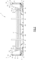
Fig.2] Figure 2 is a side view of a flat rack equipped with protection assemblies according to the invention; - [
Fig.3] Figure 3 is a partial perspective view of a first protection assembly according to the invention, with the cover in its retracted submarine line section loading configuration; - [
Fig.4] Figure 4 is a side view of the loading of submarine line sections into the flat rack offigure 2 ; - [
Fig.5] Figure 5 is a view similar tofigure 3 , in which the covering is in its deployed configuration to close a storage volume above ends of the submarine line sections; - [
Fig.6] Figure 6 is a variant of a cover in another protection assembly according to the invention; - [
Fig.7] Figure 7 is a side view of the flat rack offigure 2 , mounted on an onshore ground vehicle. - A
flat rack 6, equipped withprotection assemblies 8 according to the invention to receive ends ofsubmarine line sections 12 is shown infigure 2 . - The
flat rack 6 is intended to be used in anoffshore recovery installation 10 depicted infigure 1 , to recover asubmarine line 11 and to process it in severalsubmarine line sections 12. - The
recovery installation 10 is intended to be operated over a body ofwater 14 to recover thesubmarine line 11 in the body ofwater 14. - The body of
water 14 is for example a sea, an ocean, a lake, and/or a river, its depth is comprised generally between 10 m and 3000 m. - The
submarine line sections 12 are for example sections of flexible pipe, in particular built according with the standards API 17J (Specification for Unbonded Flexible Pipe, 4th edition - May 2014) and API RP 17B (Recommended Practice for Flexible Pipe, 5th edition - May 2014) established by the American Petroleum Institute. Thesubmarine line 11 is advantageously an unbonded flexible pipe. At least two adjacent layers of the flexible pipe are free to move longitudinally with respect to each other during flexure of the pipe. - In the example of
figure 1 , eachsubmarine line section 12 has an axis and delimits a central passage for circulation of a fluid, advantageously a petroleum fluid. The central passage diameter advantageously ranges from 15 cm to 60 cm. - Alternatively, the
submarine line sections 12 are sections of a Hybrid Flexible Pipe (HFP), in particular built according with the standards DNVGL-ST-F119 (Thermoplastic Composite Pipes, Edition September 2019) established by the DNV (Det Norske Veritas GL). The hybrid flexible pipe is advantageously an unbonded pipe. At least two adjacent layers of the hybrid flexible pipe are free to move longitudinally with respect to each other during flexure of the pipe. - Alternatively, the
submarine line sections 12 are produced from another type of flexible pipe, such as a bonded flexible pipe, designed, manufactured and used according with the standards API RP 17B (Recommended Practice for Flexible Pipe, 5th edition - March 2014), API 7K (Drilling and Well Servicing Equipment, 6th edition - December 2015), API 16C (Choke and Kill Equipment, 3rd edition - March 2021) and API 17K (Specification for Bonded Flexible Pipe, 3rd edition - August 2017) established by the American Petroleum Institute. - Again alternatively, the
submarine line sections 12 are produced from an umbilical, as defined in ISO 13628-5 "Petroleum and natural gas industries - Design and operation of subsea production systems - Part 5: Subsea umbilicals" published in December 2009 by the International Organization for Standardization, API 17E "Specification for Subsea Umbilicals", 5th Edition - July 2017, established by the American Petroleum Institute, and IEC60183:2015, January 2015, IEC60840:2020, May 2020 and/or IEC63026:2019, December 2019 , established by the International Electrotechnical Commission (IEC), all provide standards for the design and manufacture of umbilicals and power cables. - Alternatively again, the submarine line sections are produced from single rigid metallic pipe including for example mechanically lined pipe (MLP) or polymer lined pipe (PLP), or from rigid metallic pipe-in-pipe (PiP), as defined in the offshore standard DNVGL-ST-F101 "Submarine Pipeline Systems", August 2021, established by the DNV (Det Norske Veritas GL).
- The
submarine line sections 12 are obtained by successively transversely cutting thesubmarine line 11 into thesubmarine line sections 12. - Each
submarine line section 12 has a length advantageously comprised between 10 m and 20 m. Thesubmarine line sections 12 are transported inflat racks 6 equipped withprotection assemblies 8 from their offshore recovery site to an onshore decommissioning facility where they are deconstructed and their materials recycled. - In reference to
figure 1 , therecovery installation 10 comprises arecovery vessel 20, aline recovery system 22 and aprocessing stage 24, to process anupper end region 26 of thesubmarine line 11 recovered with theline recovery system 22 into severalsubmarine line sections 12. Theline recovery system 22 and theprocessing stage 24 are here carried by therecovery vessel 20 - The
recovery installation 10 further comprises, downstream of theprocessing stage 24, a handling andstorage stage 28 comprising at least aflat rack 6 equipped withprotection assemblies 8 to carry and store thesubmarine line sections 12 processed in theprocessing stage 24. - In this example, the
recovery vessel 20 is a ship floating on the surface of the body of water. In variant, therecovery vessel 20 is a platform, in particular a floating platform. - The
recovery vessel 20 has ahull 30, floating on the surface of the body ofwater 14 and at least adeck 32 onto which theline recovery system 22, theprocessing stage 24, and thestorage stage 28 are positioned. - In the example of
figure 1 , thehull 30 has amoon pool 34 extending vertically through thedeck 32 and through thehull 30 to provide a central vertical access in the body ofwater 14. - Alternatively, recovery operations can take place over the side or at the back of the
vessel 20. - The
line recovery system 22 is configured to vertically or horizontally lift the line above the surface of the body ofwater 14 to bring theupper end region 26 of thesubmarine line 11 above thedeck 32 to theprocessing stage 24. - Alternatively, the
submarine line 11 may be lifted via a tiltable or tilted line recovery system 22 (i.e. not completely vertical and not completely horizontal) above the surface of the body ofwater 14. The said system being inclined over the side, at the middle or at the back of thevessel 20. Typically, said tiltable systems are actually horizontal lay systems which are slightly inclined of a few degrees, for example between 10° and 45°, in relation to thedeck 32 level of therecovery vessel 20. - In the example of
figure 1 , which concerns in particular flexible lines, theline recovery system 22 is a vertical lift system (VLS) configured to continuously lift a vertical section of thesubmarine line 11 and to redirect it above thehull 30. Thevertical lifting system 22 is configured to recover thesubmarine line 11 in a notably J shape configuration. - In a variant (not shown), the
line recovery system 22 comprises another type of lifting system able to carry out a recovery in a S-lay or J-lay configuration. - In reference to
figure 1 , thevertical lifting system 22 comprises atower 36 mounted on thedeck 32, andtensioners 38 carried by thetower 36 to continuously lift thesubmarine line 11. Theline recovery system 22 further advantageously comprises a redirectingmechanism 40 to bend thesubmarine line 11 at the top of thetower 36 and redirect it towards thedeck 32. - The
tower 36 is here mounted above themoon pool 34. Themoon pool 34 is typically arranged through thehull 30 of therecovery vessel 20, at the middle/center. When therecovery vessel 20 does not comprise amoon pool 34, thetower 36 is advantageously mounted near a side of thehull 30 to lift thesubmarine line 11 from the side. - As shown in
figure 1 , theprocessing stage 24 here comprises at least a dividingsystem 44 positioned transversely with regards to thesubmarine line 11 being divided. - In the example of
figure 1 , each dividingsystem 44 is a line cutter, configured to transversely cut thesubmarine line 11 substantially perpendicularly to its axis. - The handling and
storage stage 28 comprises astorage area 50 of thedeck 32, and at least acrane 52, to carry thesubmarine line sections 12 to the storage area 130. - In the example of
figure 1 , theflat racks 6 equipped withprotection assemblies 8 are positioned in thestorage area 50 with an alignment transverse to the axis in which they are lay in theprocessing stage 24. - As shown in
figure 4 , thecrane 52 is equipped with a deployablelifting crane wire 53 with at least asling 54 mounted at its free end. The or eachsling 54 is configured to be tied around severalsubmarine line sections 12 stored in theprocessing stage 24 to jointly lift all thesubmarine line sections 12 from theprocessing stage 24 and lower them into theflat rack 6, as it will be described below. - As shown in
figure 2 , theflat rack 6 comprises ahorizontal tray 60 extending along a longitudinal axis A-A', and twoprotection assemblies 8 positioned facing each other at the longitudinal ends of thehorizontal tray 60. - In this example, the
protection assemblies 8 are separate assemblies placed and potentially fixed at the ends of thehorizontal tray 60. In a variant, which will be described below, at least oneprotection assembly 8 is an integral part of theflat rack 6 positioned at the end of theflat rack 6. - In the example of
figure 2 , theflat rack 6 comprises two end transversevertical plates 64, protruding from the longitudinal ends of thehorizontal tray 60. The end transversevertical plates 64 are equipped with at least a lifting point (not shown) to allow lifting of eachprotection assembly 8. - Advantageously, in particular when the
line sections 12 are flexible line sections, theflat rack 6 further comprises lower supportingblocks submarine line sections 12, extending transversely on thehorizontal tray 60 between theprotection assemblies 8. - The
flat rack 6 advantageously comprisesside stanchions 68 protruding from the sides of thehorizontal tray 60 in the intermediate space defined longitudinally between theprotection assemblies 8. - The
horizontal tray 60 generally has a length greater than the length of thesubmarine line sections 12. The length of thehorizontal tray 60, taken between thelongitudinal edges 70 of the tray is generally comprised between 15 m and 25 m. The width of thehorizontal tray 60 is smaller than its length. It is generally comprised between 5 m and 15 m. - The
horizontal tray 60 dimensions are preferably chosen such that it is configured to be lifted and fixed on atrailer 72 of atruck 74 shown infigure 7 . - In a variant (not shown), the
horizontal tray 60 may be lifted and fixed on another vehicle such as a train, or on a barge or other vessels, in place of atruck 74. - Thus, the
flat rack 6 containingsubmarine line sections 12 can thus be easily lifted from the handling andstorage area 50, to atrailer 72 onshore, to be transported towards an onshore submarine line section processing installation. - As shown on
figures 2 and3 , eachprotection assembly 8 is fitted at a longitudinal end of thehorizontal tray 60 along atransverse edge 70 of thehorizontal tray 60. In this example, theprotection assemblies 8 are laid on thehorizontal tray 60, in contact with the transversevertical plate 64. - As visible in
figure 3 , eachprotection assembly 8 comprises ahorizontal base 80, applied on the upper surface of thehorizontal tray 60, atransverse end wall 82, protruding from a transverse end edge of thehorizontal base 80 and twoside walls 84, each extending between arespective side edge 86 of thetransverse end wall 82 to a respectivelateral edge 88 of thehorizontal base 80. - The
transverse end wall 82 and theside walls 84 define astorage volume 89 to receive the ends ofsubmarine line sections 12 positioned on thehorizontal tray 60. Theside walls 84 may also be equipped with lifting point to allow lifting of eachprotection assembly 8. - Each
protection assembly 8 further comprises a transverselower wall 90 connecting the free ends of theside walls 84 longitudinally apart from thetransverse end wall 82. The transverselower wall 90 defines, with theside walls 84 and thetransverse end wall 82, alower retention basin 92 to collect liquids and solids from ends of thesubmarine line sections 12. - Optionally, the
protection assembly 8 further comprisesbaffles 94 protruding in theretention basin 92. - The
lower retention basin 92 can be advantageously provided with an opening fitted with a tap or plug (not shown) configured to be open from a closed rest configuration to drain the content of thebasin 92 at the appropriate time and location. Such an opening or a similar opening put closely can be also used as a monitoring point for detecting hazardous contaminants inside thebasin 92, e.g. for sniffing hazardous gases. - Alternatively, at least one of the
transverse end wall 82 and/or of theside walls 84 could be provided with an opening fitted with a tap or plug (not shown) that allows monitoring of hazardous contaminants in thestorage volume 89 of theprotection assembly 8, e.g. for sniffing hazardous gases. - The
protection assembly 8 also comprises aflexible cover 96, movable into thestorage volume 89 between a retracted position (seefigure 3 ), to allow insertion and load of the ends of thesubmarine line sections 12 in thestorage volume 89, and a deployed configuration (seefigure 5 ), to close thestorage volume 89 above the ends of thesubmarine line sections 12. - The
protection assembly 8 further comprises adetachable strap 98, visible infigure 5 , to secure theflexible cover 96 above the ends of thesubmarine line sections 12. - The
horizontal base 80 is for example made of a metal sheath. The width of thehorizontal base 80 is substantially equal to the width of theflat rack 6, for example comprised between 90% and 100% of the width of theflat rack 6. - The length of the
horizontal base 80 is smaller than half the length of theflat rack 6. The length of thehorizontal base 80 is for example smaller than 30%, preferably smaller than 10% of the length of theflat rack 6. - The
transverse end wall 82 protrudes at a longitudinal end of thehorizontal base 80. It extends over the whole width of thehorizontal base 80. Its height is preferably smaller or equal to the height of thetransverse plate 64. It is comprised for example between 90% and 100% of the height of thetransverse plate 64. - In this example, the
transverse end wall 82 is also made of a metal sheath. - Each
side wall 84 has anupper edge 100 which is at least partially inclined. In the example offigure 3 , theupper edge 100 has a firsthorizontal region 102, connected to thetransverse end wall 82 preferentially at a height equal to the height of thetransverse end wall 82, and asecond region 104, inclined downwardly towards a respective longitudinal end of thehorizontal base 80 opposed to thetransverse end wall 82. Theupper edge 100 preferentially has a roundedtransition region 106 between thefirst region 102 and thesecond region 104. - The
storage volume 89 is thus bounded vertically by thetransverse end wall 82, by eachside wall 84 and downwardly by thehorizontal base 80. Thestorage volume 89 opens upwardly in anupper insertion passage 108 through which the ends of thesubmarine line sections 12 can be loaded into thestorage volume 89. - The
storage volume 89 also opens longitudinally facing thestorage volume 89 of anotherprotection assembly 8 located at the opposite end of thehorizontal tray 60. - The transverse
lower wall 90 is preferentially made of a metal sheet. - The height of the transverse
lower wall 90 is smaller than the height of thetransverse end wall 82. The height of the transverselower wall 90 is for example smaller than 50% of the height of thetransverse end wall 82. - The transverse
lower wall 90 may have a lip curved towards thetransverse end wall 82 to limit sloshing during movements and handling. - In another variant, a timber dunnage is attached to the transverse
lower wall 90 opposite to theretention basin 92 - The
retention basin 92 defines a laterally and downwardly closed retention volume to receive liquids and solids leaking from the open ends of thesubmarine line sections 12. It prevents such liquids and solids to drain on thehorizontal tray 60 or/and away from theflat rack 6. - When present, the
baffles 94 protrude in theretention basin 92. They prevent splashing of liquids contained in theretention basin 92 during handling and transportation of theflat track 6. - In a variant not shown, the
retention basin 92 contains a truss received in theretention basin 92, in place of thebaffles 94, or above thebaffles 94. - The
flexible cover 96 is for example formed of a flexible tarp. Theflexible cover 96 is for example made of plastic, in particular polyethylene fabric, polyvinyl chloride (PVC), Chemical Resistant PVC, Silicone Coated Fibreglass - In the example of
figure 3 , theflexible cover 96 has afirst edge 112, fixed to thetransverse end wall 82, at a lower position on thetransverse end wall 82. It has a secondlongitudinal edge 114 which is free to move with regard to thefirst edge 112. - In a variant not shown, the second
longitudinal edge 114 is rolled up to the upper edge of thetransverse end wall 82 and secured with a thong. - As mentioned previously, the
flexible cover 96 is movable between the retracted configuration, shown infigure 3 and the deployed configuration shown infigure 5 . - In the retracted configuration, the
flexible cover 96 is at least retracted away from theupper insertion passage 108 to allow a vertical downward insertion of at least one end of a submarine line section into thestorage volume 89. - In the particular configuration of
figure 3 , theflexible cover 96 is folded back above the upper edge of thetransverse end wall 82. It has one base region extending vertically along an inner face of thetransverse end wall 82 in thestorage volume 89 and one folded region extending away from thestorage volume 89 along an outer face of thetransverse end wall 82. The freesecond edge 114 is placed away from thestorage volume 89. - In the deployed configuration shown in
figure 5 , theflexible cover 96 is positioned over the ends of thesubmarine line sections 12, inside thestorage volume 89. Its lateral edges are folded along the end sections of thesubmarine lines section 12 to horizontally cover the open ends of thesubmarine line sections 12. - This configuration prevents liquids and/or solids to escape above the
flexible cover 96. Thestorage volume 89 is closed above the ends of thesubmarine line sections 12. - The
strap 98 is detachable. It is configured to be detachably engaged around thesubmarine line sections 12 and above theflexible cover 96 to apply theflexible cover 96 on the ends of thesubmarine line sections 12, as shown infigure 5 . - In reference to
figure 2 , at least two lower supportingblocks horizontal tray 60. The lower supportingblocks horizontal tray 60. - In the example of
figure 2 , the two lower supportingblocks tray 60, longitudinally apart from each other, and at a longitudinal distance from the longitudinal ends of theside walls 84 opposed to thetransverse end wall 82. - At least a first lower supporting
block 66A closer to the endtransverse wall 82 has a height which is greater than the height of a secondlower block 66B located further away from the endtransverse wall 82. - As shown in
figure 2 , this allows thesubmarine line sections 12, when flexible, to be supported in a U shape configuration, the U-shape opening upwardly. - When present, the
stanchions 68 protrude above thehorizontal tray 60, in the intermediate region between theprotection assemblies 8. - In the example of
figure 2 , theflat rack 6 comprises at least twostanchions 68 on each side, positioned longitudinally apart from one another, and apart from theprotection assemblies 8. - The height of the
stanchions 68 is equal or greater to the height of theprotection assemblies 8. Thus, thestanchions 68 are able to laterally retain thesubmarine line sections 12 when they are stored on thehorizontal tray 60. - The
flat rack 6 is here open upwardly above thehorizontal tray 60. - The use of a
flat rack 6 equipped with aprotection assembly 8 according to the invention, during the recovery of asubmarine line 11 will be now described. - Initially, in reference to
figure 1 , thesubmarine line 11 is recovered from the body ofwater 14 on therecovery vessel 20 using theline recovery system 22. - The
tensioners 38 lift thesubmarine line 11 and transport itsupper end region 26 to theprocessing stage 24. - In the
processing stage 24, the or each dividingsystem 44 is activated to cut theupper end region 26 of thesubmarine line 11 in severalsubmarine line sections 12. Thesubmarine line sections 12 are temporarily retrieved in theprocessing stage 24. - As shown in
figure 4 , severalsubmarine line sections 12 are tied withslings 54 and are seized by the deployinglifting wire 53 of thecrane 52. Thesubmarine line sections 12 are jointly lifted from theprocessing stage 24 and are moved to thestorage area 50. - In the
storage area 50, at least aflat rack 6 equipped withprotection assemblies 8 is provided to receive the bundle ofsubmarine line sections 12. - The
flexible cover 96 is placed in its retracted configuration shown infigure 2 , at least partially retracted away from theupper insertion passage 108. Thesubmarine line sections 12 are then lowered by thecrane 52 to be laid on thehorizontal tray 60 of theflat rack 6. - The uncapped ends of the
submarine line sections 12 enter downwardly in thestorage volume 89 through theupper insertion passage 108. - Advantageously, the central regions of the
submarine line sections 12 lay on the lower supportingblocks blocks submarine line section 12. - Once the
submarine line sections 12 are received within thestorage volume 89, theflexible cover 96 is moved from the retracted configuration to the deployed configuration in thestorage volume 89, to cover the ends of thesubmarine line sections 12. - In the example of
figure 3 , the secondfree edge 114 is pivoted about thefirst edge 112. The folded region of theflexible cover 96 is thus extended through thestorage volume 89 to cover the ends of thesubmarine line sections 12 as shown infigure 5 . - The
strap 98 is then mounted transversally around theflexible cover 96 to maintain theflexible cover 96 applied on the ends of thesubmarine line sections 12. - Should some liquids and/or solids leak from an end of a
submarine line section 12, it falls down in theretention basin 92. Theretention basin 92 is generally drained before theflat rack 6 is lifted off thevessel 20, and ideally during transport, theretention basin 92 is empty. Nevertheless, if some liquid remains, it is held there by thebaffles 94, when present, during handling and transportation of theflat rack 6. - The ends of the
submarine line section 12 remain uncapped, but are fully covered by theflexible cover 96. This protects users from being exposed to the liquids and solids contained therein. Theprotection assembly 8 makes sure that it prevents any loss of contents which may be caused under normal conditions of transport. - Once the
flat rack 6 is unloaded onshore from therecovery vessel 20, it can be placed on a surface of a ground vehicle, to be transported onshore on the ground vehicle. In the example offigure 7 , the ground vehicle is atruck 74 having atrailer 72 onto which theflat rack 6 is detachably fixed. - Alternatively, the
truck 74 may be replaced by another vehicle such as a train, or by a barge or other vessels. - Thanks to the provision of
protection assemblies 8 on theflat rack 6, the ends of thesubmarine line section 12 are confined within thestorage volume 89, being covered by theflexible cover 96. - Capping each end of
submarine line sections 12 on therecovery vessel 20 is therefore not required. Thus, the operators do not need to access each end of the submarine line sections. They merely move theflexible cover 96 from the retracted configuration to the deployed configuration and tie thestrap 98. - This allows a safe, yet very simple transportation of the
submarine line sections 12 in theflat rack 6, without having to cap each end of eachsubmarine line section 12 with a plastic cap. - The risk of liquids and/or solids leakage is avoided, in particular when the
retention basin 92 is equipped withinner baffles 96 or with a truss that prevents splashing of the liquids. - The handling and transportation of the
submarine line sections 12 withflat racks 6 according to the invention is therefore cheaper and simpler and does not significantly expose operators to radioactive materials. Theflat racks 6 according to the invention also avoid using large quantities of plastic, limiting waste. - In a variant, not shown, the
protection assembly 8 is an integral part of theflat rack structure 6. - The
horizontal base 80 is formed of the upper surface of thehorizontal tray 60. Thetransverse end wall 82 is formed by thetransverse plate 64 of theflat rack 6. - The
side walls 84 are permanently fixed along the vertical edges of thetransverse plate 64 and along the lateral edges of thehorizontal tray 60. - In a variant of any of the previous embodiments, shown in
figure 6 , theflexible cover 96 is fixed along theupper edges 100, preferably along the first andsecond regions side walls 84, for example bydetachable attachments 120. For example, theflexible cover 96 is secured on eachside wall 84 of theprotection assembly 8 with fixing hooks as detachable attachments. - In a variant, the
detachable attachments 120 are snap fasteners. - The
flexible cover 96 comprises aflap 122 which is deployed on thesubmarine line sections 12 in the deployed configuration. Theflap 122 defines with the transverselower wall 90, alower passage 124 through which thesubmarine line sections 12 enter thestorage volume 89. - In another variant (not shown), at least a first lower supporting
block 66A closer to the endtransverse wall 82 has a height which is smaller than the height of a secondlower block 66B located further away from the endtransverse wall 82. - Given the different heights of the supporting
blocks submarine line section 12, when flexible, adopts a substantially inverted U shape configuration with its ends lowered below the central region of eachsubmarine line section 12. - In another variant (not shown), the second supporting
block 66B located further away from thetransverse end wall 82 has an adjustable height that changes the curvature offlexible pipe sections 12 between concave and convex. - In another variant (not shown), adapted in particular to
rigid pipe sections 12, the second supportingblock 66B has height that allowsrigid pipe sections 12 to sit flat between both supportingblocks blocks - In another variant (not shown) of each of the previous embodiments, the
protection assembly 8 comprises an upper horizontal cross member connecting theside walls 84 at the top of thestorage volume 89, preferably in the vicinity of the firsthorizontal region 102 of the upper edges 100. - The upper horizontal cross member stiffens the structure of the protection assembly in particular between the
side walls 84. - In another variant (not shown) of each of the previous embodiments, each transverse
vertical plate 64 of theflat rack 6 comprise two side vertical posts which protrude axially towards the opposite transversevertical plate 64. - The
transverse end wall 82 of theprotection assembly 8 correspondingly defines, along itstransverse side edge 86, a profiled vertical recess of corresponding shape, which accommodates a side vertical post of theflat rack 6. Eachside edge 86 of thetransverse end wall 82 laterally abuts against a corresponding vertical post of theflat rack 6. Theprotection assembly 8 is thus transversely secured between the side vertical posts of the transversevertical plate 64.
Claims (15)
- A protection assembly (8) to receive ends of submarine line sections (12), intended to be placed on a flat rack (6) or to be part of a flat rack (6), the protection assembly (8) comprising a horizontal base (80) which extends out along a longitudinal axis (A-A');
characterized in that the protection assembly (8) comprises a vertically protruding transverse end wall (82) at an end of the horizontal base (80) and two vertically protruding side walls (84) extending from the transverse end wall (82) along sides of the horizontal base (80), the transverse end wall (82) and the side walls (84) delimiting a storage volume (89) to receive the ends of the submarine line section (12), the storage volume (89) emerging upwardly via an upper insertion passage (108), the protection assembly (8) comprising at least a flexible cover (96) movable between a retracted submarine line section loading configuration, at least partially retracted away from the upper insertion passage (108) to allow insertion in the storage volume (89) of ends of submarine line sections (12) through the upper insertion passage (108) and a deployed configuration in the storage volume (89) to cover the ends of the submarine line sections (12). - The protection assembly (8) according to claim 1, comprising a strap (98) to transversely maintain the cover (96) applied on ends of the submarine line sections (12) in the deployed configuration.
- The protection assembly (8) according to any one of the preceding claims, wherein the flexible cover (96) has at least a first edge (112) fixed on the horizontal base (80), on the transverse end wall (82) or/and a side wall (84), the flexible cover (96) being foldable between the retracted configuration and the deployed configuration with regards to the first edge (112).
- The protection assembly (8) according to any one of the preceding claims, wherein in the deployed position, the flexible cover (96) is extended in the storage volume (89).
- The protection assembly (8) according to any one of the preceding claims, wherein the side walls (84) have an at least partially inclined upper edge (100), the upper edge (100) being inclined downwardly away from the transverse end wall (82).
- The protection assembly (8) according to any one of the preceding claims, comprising a transverse lower wall (90), positioned apart from the transverse end wall (82), the transverse lower wall (90), the side walls (84), and the transverse end wall (82) defining a liquid retention basin (92) to collect liquids and/or solids leaking from the flexible end sections (12).
- The protection assembly (8) according to claim 6, comprising at least a baffle (94) or/and a truss received in the retention basin.
- The protection assembly (8) according to any one of claims 6 or 7, wherein the transverse lower wall (90) connects the side walls (84), preferably the ends of the side walls (84), a height of the transverse lower wall (90) being smaller than 50% of a height of the transverse end wall (82).
- A flat rack (6), to receive submarine line sections (12), the flat rack (6) comprising a horizontal tray (60) extending along a longitudinal axis (A-A'), and at least one protection assembly (8) according to any one of the preceding claims, located at an end of the horizontal tray (60), preferably two protection assemblies (8) according to any one of the preceding claims, located at opposed ends of the horizontal tray (60).
- The flat rack (6) according to claim 9, wherein the protection assembly (8) is part of the flat rack (6), the horizontal base (80) being formed by an upper surface of the horizontal tray (60), or wherein the protection assembly (8) is a separate assembly placed on the horizontal tray (60).
- The flat rack (6) according to any one of claims 9 to 10, comprising at least a submarine line section lower supporting block (66A, 66B) in a half region of the horizontal tray (60), the lower supporting block (66A, 66B) protruding from the horizontal tray (60) at a distance from the longitudinal ends of the side walls (84) opposed to the transverse end wall (82), the lower supporting block (66A, 66B) being preferably a transverse lower block.
- The flat rack (6) according to claim 11, comprising at least two separate lower supporting blocks (66A, 66B) in the same half region of the horizontal tray (60), a first lower supporting block (66A) closer to the transverse end wall (82) having a height greater or smaller than the height of a second lower supporting block (66B) located further away from the transverse end wall (82).
- The flat rack (6) according to any one of claims 9 to 12, comprising at least a side retaining stanchion (68) extending upwardly from a side of the horizontal tray (60).
- A method to store and transport submarine line sections (12) comprising :- providing at least one flat rack (6) according to any one of claims 9 to 13, the flexible cover (96) being in its retracted configuration,- loading submarine line sections (12) in the at least one flat rack (6),- inserting ends of the submarine line sections (12) in the storage volume (89) of the protection assembly (8) through the upper insertion passage (108), the ends of the submarine line sections (12) being uncapped;- moving the flexible cover (96) from the retracted configuration to the deployed configuration to cover the ends of the submarine line sections (12).
- The method according to claim 14, wherein providing the at least one flat rack (6) is carried out on a deck of a vessel (20) having a submarine line recovery system (22) and a submarine line processing stage (24) to divide the submarine line (11) in submarine line sections (12), the method comprising loading the submarine line sections (12) in the at least one flat rack (6) from the processing stage (24), the method comprises transferring the at least one flat rack (6) onshore to an onshore vehicle such as a truck or a train or transferring the at least one flat rack (6) offshore to another vessel.
Priority Applications (3)
| Application Number | Priority Date | Filing Date | Title |
|---|---|---|---|
| EP23306282.7A EP4497701B1 (en) | 2023-07-25 | 2023-07-25 | Protection assembly to receive ends of submarine line sections, related flat rack and method |
| AU2024298811A AU2024298811A1 (en) | 2023-07-25 | 2024-07-23 | Protection assembly to receive ends of submarine line sections, related flat rack and method |
| PCT/EP2024/070922 WO2025021825A1 (en) | 2023-07-25 | 2024-07-23 | Protection assembly to receive ends of submarine line sections, related flat rack and method |
Applications Claiming Priority (1)
| Application Number | Priority Date | Filing Date | Title |
|---|---|---|---|
| EP23306282.7A EP4497701B1 (en) | 2023-07-25 | 2023-07-25 | Protection assembly to receive ends of submarine line sections, related flat rack and method |
Publications (2)
| Publication Number | Publication Date |
|---|---|
| EP4497701A1 true EP4497701A1 (en) | 2025-01-29 |
| EP4497701B1 EP4497701B1 (en) | 2026-04-15 |
Family
ID=87556018
Family Applications (1)
| Application Number | Title | Priority Date | Filing Date |
|---|---|---|---|
| EP23306282.7A Active EP4497701B1 (en) | 2023-07-25 | 2023-07-25 | Protection assembly to receive ends of submarine line sections, related flat rack and method |
Country Status (3)
| Country | Link |
|---|---|
| EP (1) | EP4497701B1 (en) |
| AU (1) | AU2024298811A1 (en) |
| WO (1) | WO2025021825A1 (en) |
Citations (4)
| Publication number | Priority date | Publication date | Assignee | Title |
|---|---|---|---|---|
| WO2014047055A1 (en) * | 2012-09-19 | 2014-03-27 | Knight Oil Tools, Llc | Modular pipe basket |
| WO2015081373A1 (en) * | 2013-12-04 | 2015-06-11 | Noske Anthony | Transport container |
| RU180934U1 (en) * | 2017-04-26 | 2018-06-29 | РЕЙЛ 1520 АйПи ЛТД | REMOVABLE BODY OF THE FREIGHT WAGON |
| WO2021118793A1 (en) | 2019-12-12 | 2021-06-17 | Amazon Technologies, Inc. | Speech processing |
-
2023
- 2023-07-25 EP EP23306282.7A patent/EP4497701B1/en active Active
-
2024
- 2024-07-23 AU AU2024298811A patent/AU2024298811A1/en active Pending
- 2024-07-23 WO PCT/EP2024/070922 patent/WO2025021825A1/en active Pending
Patent Citations (4)
| Publication number | Priority date | Publication date | Assignee | Title |
|---|---|---|---|---|
| WO2014047055A1 (en) * | 2012-09-19 | 2014-03-27 | Knight Oil Tools, Llc | Modular pipe basket |
| WO2015081373A1 (en) * | 2013-12-04 | 2015-06-11 | Noske Anthony | Transport container |
| RU180934U1 (en) * | 2017-04-26 | 2018-06-29 | РЕЙЛ 1520 АйПи ЛТД | REMOVABLE BODY OF THE FREIGHT WAGON |
| WO2021118793A1 (en) | 2019-12-12 | 2021-06-17 | Amazon Technologies, Inc. | Speech processing |
Non-Patent Citations (3)
| Title |
|---|
| "Petroleum and natural gas industries - Design and operation of subsea production systems - Part 5: Subsea umbilicals", December 2009, INTERNATIONAL ORGANIZATION FOR STANDARDIZATION |
| "Specification for Subsea Umbilicals", July 2017, AMERICAN PETROLEUM INSTITUTE |
| "Submarine Pipeline Systems", August 2021, DNV |
Also Published As
| Publication number | Publication date |
|---|---|
| AU2024298811A1 (en) | 2026-02-05 |
| WO2025021825A1 (en) | 2025-01-30 |
| EP4497701B1 (en) | 2026-04-15 |
Similar Documents
| Publication | Publication Date | Title |
|---|---|---|
| US20110318107A1 (en) | Apparatus and method for undersea oil leakage containment | |
| GB2223458A (en) | Installing a jacket of an artificial island on to an underwater base | |
| RU2721212C2 (en) | Device for protection of underwater equipment | |
| EP0145214B1 (en) | Marine structure having flow conduits and method of installing such conduits | |
| CN101356092A (en) | mooring system | |
| EP4497701B1 (en) | Protection assembly to receive ends of submarine line sections, related flat rack and method | |
| MX2013008800A (en) | Containment unit for marine hydrocarbons and method of using same. | |
| EP0170698A4 (en) | Oil storage and transfer facility. | |
| ES2250859T3 (en) | EFFLUENT RECOVERY PROCEDURE AND INSTALLATION AT SEA WITH THE HELP OF A LAUNCHER DEPOSIT. | |
| US20190106854A1 (en) | Systems, apparatuses, and methods for removing fixed offshore platforms | |
| NO771975L (en) | DEVICE FOR LIQUID OIL STORAGE TANK | |
| US10793350B2 (en) | Subsea storage unit, system and method | |
| WO2013144724A2 (en) | Pipeline and method of laying a pipeline | |
| US20210395003A1 (en) | Method and apparatus for management of fluids in an underwater storage tank | |
| EP4471310A1 (en) | Solids capturing device for a flexible pipe immersed in a body of water, related assembly and method | |
| US9562647B2 (en) | Cryogenic fluids transfer system with transfer spills containment | |
| KR20150028439A (en) | Natural flowing type crude oil loading and unloading apparatus | |
| EP4534401B1 (en) | A recovery installation to recover a submarine line in a body of water, and corresponding recovery method | |
| RU2720461C2 (en) | Device lowering method | |
| WO2020251363A1 (en) | Underwater production system protection and storage tank | |
| RU2096842C1 (en) | Method for re-storage of radioactive and toxic wastes lying on water reservoir bottom | |
| RU65444U1 (en) | FUEL FILLING COMPLEX FOR WATER VESSELS | |
| WO1998008735A1 (en) | Device for handling of a hose | |
| NL9100072A (en) | Container with floating cover for liq. manure - comprises flexible polyvinyl chloride material attached to ring form tubular structure contg. polyurethane foam |
Legal Events
| Date | Code | Title | Description |
|---|---|---|---|
| PUAI | Public reference made under article 153(3) epc to a published international application that has entered the european phase |
Free format text: ORIGINAL CODE: 0009012 |
|
| STAA | Information on the status of an ep patent application or granted ep patent |
Free format text: STATUS: THE APPLICATION HAS BEEN PUBLISHED |
|
| AK | Designated contracting states |
Kind code of ref document: A1 Designated state(s): AL AT BE BG CH CY CZ DE DK EE ES FI FR GB GR HR HU IE IS IT LI LT LU LV MC ME MK MT NL NO PL PT RO RS SE SI SK SM TR |
|
| STAA | Information on the status of an ep patent application or granted ep patent |
Free format text: STATUS: REQUEST FOR EXAMINATION WAS MADE |
|
| 17P | Request for examination filed |
Effective date: 20250709 |
|
| P01 | Opt-out of the competence of the unified patent court (upc) registered |
Free format text: CASE NUMBER: UPC_APP_3327_4497701/2025 Effective date: 20250814 |
|
| GRAJ | Information related to disapproval of communication of intention to grant by the applicant or resumption of examination proceedings by the epo deleted |
Free format text: ORIGINAL CODE: EPIDOSDIGR1 |
|
| GRAP | Despatch of communication of intention to grant a patent |
Free format text: ORIGINAL CODE: EPIDOSNIGR1 |
|
| GRAP | Despatch of communication of intention to grant a patent |
Free format text: ORIGINAL CODE: EPIDOSNIGR1 |
|
| STAA | Information on the status of an ep patent application or granted ep patent |
Free format text: STATUS: GRANT OF PATENT IS INTENDED |
|
| RIC1 | Information provided on ipc code assigned before grant |
Ipc: B65D 59/08 20060101AFI20251127BHEP Ipc: B65D 85/20 20060101ALI20251127BHEP Ipc: B65D 88/12 20060101ALI20251127BHEP Ipc: B65D 59/00 20060101ALI20251127BHEP |
|
| INTG | Intention to grant announced |
Effective date: 20251212 |
|
| GRAS | Grant fee paid |
Free format text: ORIGINAL CODE: EPIDOSNIGR3 |
|
| GRAA | (expected) grant |
Free format text: ORIGINAL CODE: 0009210 |
|
| STAA | Information on the status of an ep patent application or granted ep patent |
Free format text: STATUS: THE PATENT HAS BEEN GRANTED |
|
| AK | Designated contracting states |
Kind code of ref document: B1 Designated state(s): AL AT BE BG CH CY CZ DE DK EE ES FI FR GB GR HR HU IE IS IT LI LT LU LV MC ME MK MT NL NO PL PT RO RS SE SI SK SM TR |
|
| REG | Reference to a national code |
Ref country code: CH Ref legal event code: F10 Free format text: ST27 STATUS EVENT CODE: U-0-0-F10-F00 (AS PROVIDED BY THE NATIONAL OFFICE) Effective date: 20260415 |