EP4497653A1 - Informationsverarbeitungsvorrichtung und informationsverarbeitungsverfahren zur schätzung der dreidimensionalen lage eines eisenbahngleises - Google Patents
Informationsverarbeitungsvorrichtung und informationsverarbeitungsverfahren zur schätzung der dreidimensionalen lage eines eisenbahngleises Download PDFInfo
- Publication number
- EP4497653A1 EP4497653A1 EP24160333.1A EP24160333A EP4497653A1 EP 4497653 A1 EP4497653 A1 EP 4497653A1 EP 24160333 A EP24160333 A EP 24160333A EP 4497653 A1 EP4497653 A1 EP 4497653A1
- Authority
- EP
- European Patent Office
- Prior art keywords
- railroad track
- image
- coordinate system
- dimensional position
- information processing
- Prior art date
- Legal status (The legal status is an assumption and is not a legal conclusion. Google has not performed a legal analysis and makes no representation as to the accuracy of the status listed.)
- Pending
Links
Images






Classifications
-
- B—PERFORMING OPERATIONS; TRANSPORTING
- B61—RAILWAYS
- B61L—GUIDING RAILWAY TRAFFIC; ENSURING THE SAFETY OF RAILWAY TRAFFIC
- B61L23/00—Control, warning or like safety means along the route or between vehicles or trains
- B61L23/04—Control, warning or like safety means along the route or between vehicles or trains for monitoring the mechanical state of the route
- B61L23/041—Obstacle detection
-
- G—PHYSICS
- G06—COMPUTING OR CALCULATING; COUNTING
- G06V—IMAGE OR VIDEO RECOGNITION OR UNDERSTANDING
- G06V20/00—Scenes; Scene-specific elements
- G06V20/50—Context or environment of the image
- G06V20/56—Context or environment of the image exterior to a vehicle by using sensors mounted on the vehicle
- G06V20/58—Recognition of moving objects or obstacles, e.g. vehicles or pedestrians; Recognition of traffic objects, e.g. traffic signs, traffic lights or roads
-
- G—PHYSICS
- G06—COMPUTING OR CALCULATING; COUNTING
- G06V—IMAGE OR VIDEO RECOGNITION OR UNDERSTANDING
- G06V20/00—Scenes; Scene-specific elements
- G06V20/60—Type of objects
- G06V20/64—Three-dimensional [3D] objects
Definitions
- Approaches of the present invention relate to an information processing device and an information processing method.
- the ranging device is, for example, a LiDAR (Light Detection and Ranging) device.
- the use of the ranging device compensates for the fact that a positional relation in the depth direction of an object reflected in an image acquired by the camera is unclear when the image alone is used.
- Such a technique can be particularly useful when the operator does not visually determine presence or absence of an obstacle, for example, when the autonomous driving system is adopted.
- the train has a longer braking distance compared with an automobile and the like.
- it is necessary to detect an obstacle several hundred meters ahead.
- an incident angle of laser light is larger with respect to the railroad track. Therefore, the distance from the train to the railroad track cannot be measured by the ranging device. Therefore, the position of a railroad track present in a position far from the train cannot be specified, presence of an obstacle within a construction limit of the railroad track cannot be detected, and detection accuracy is deteriorated.
- an information processing device includes a first image acquirer configured to acquire a first image generated by an imaging device that images a forward environment of a vehicle; a railroad track detector configured to detect, from the first image, a railroad track on which the vehicle travels; a second image acquirer configured to acquire a second image including a three-dimensional position of the forward environment, the three-dimensional position being based on distance information acquired by a ranging device that measures a distance to the forward environment; and a railroad track estimator configured to specify, in the railroad track included in the first image, a target range in which a portion corresponding to the railroad track is absent in the second image and estimate, based on information concerning the railroad track on which the vehicle travels, a three-dimensional position of a railroad track portion included in the target range in the railroad track of the first image.
- FIG. 1 is a block diagram illustrating an example of an obstacle detection system 1 according to the approach.
- the obstacle detection system 1 includes a camera 2, a ranging device 3, and an obstacle detection device 4.
- FIG. 2 is a diagram illustrating the obstacle detection system 1 mounted on a car, more specifically, a first car of a train 10.
- the obstacle detection system 1 is a system for determining whether an object, that is, an obstacle that can be obstructive to traveling of the train 10 is present within a construction limit of a railroad trackT on which the train 10 travels, moves or runs.
- the obstacle is a human, a fallen object, or the like present within the construction limit of the railroad track T and does not include the railroad track T itself, the ground on which the railroad track T is disposed, and the like.
- “first car” means a frontmost car in a traveling direction of the train 10.
- the train 10 is traveling on the railroad track T.
- An object Obj1 is present on the left side of the railroad track T when viewed from the train 10.
- An object Obj2 is present on the right side of the railroad track T when viewed from the train 10.
- the obstacle detection system 1 is disposed outside the train 10. However, the obstacle detection system 1 may be disposed inside the train 10. In that case, the camera 2 and the ranging device 3 may respectively perform imaging and ranging through the windshield of the train 10. Only the camera 2 and the ranging device 3 may be mounted on the train 10. The obstacle detection device 4 may not be mounted on the train 10.
- the camera 2 is an imaging device that images a forward environment of the train 10 and generates a forward image, which is a first image.
- the camera 2 is provided in a three-dimensional first coordinate system (a first world coordinate system).
- the camera 2 is, for example, an optical camera such as a CCD (Charge Coupled Device) camera or a CMOS (Complementary Metal Oxide Semiconductor) camera or an infrared camera (a thermo-camera) or a combination of the optical camera and the infrared camera.
- an optical camera such as a CCD (Charge Coupled Device) camera or a CMOS (Complementary Metal Oxide Semiconductor) camera or an infrared camera (a thermo-camera) or a combination of the optical camera and the infrared camera.
- the forward image is, for example, a luminance image. Pixel values of the luminance image are luminance values.
- FIG. 3 is a diagram illustrating an example of a forward image captured by the camera 2.
- the railroad track T curves to the right side when viewed from the train 10.
- a sign H illustrated in FIG. 3 indicates the horizon.
- the forward image is indicated by a uv coordinate system as illustrated in FIG. 3 .
- the uv coordinate system is an image coordinate system of the camera 2.
- the ranging device 3 is a device or a sensor that measures a distance to a forward environment including the objects Obj1 and Obj2.
- the ranging device 3 generates, based on the measured distance, a 3D image, which is a second image, including a three-dimensional position of the forward environment.
- the ranging device 3 is provided in a three-dimensional second coordinate system (a second world coordinate system). Three-dimensional positions are included in each pixel of the 3D image. Distance values may be included in each pixel of the 3D image.
- An object includes the railroad track T and the ground on which the railroad track T is disposed. The distance between the object and the train 10 is strictly the distance between the object and the ranging device 3.
- the ranging device 3 includes, for example, a LiDAR.
- a wavelength of laser in use may be, for example, in an eye-safe band (for example, 1.4 ⁇ m to 2.6 ⁇ m).
- the ranging device 3 is the LiDAR.
- the ranging device 3 may generate a distance image including a distance value to the forward environment and a 3D data acquirer 43 described below may generate a 3D image from the distance image, position information of the ranging device 3, and the like.
- the ranging device 3 emits, for example, a laser pulse and scans a predetermined range of the forward environment.
- the ranging device 3 receives a pulse reflected to return from the forward environment to thereby acquire distance information to the forward environment (distance information to various objects included in the forward environment) and generates a 3D image.
- the obstacle detection device 4 is an information processing device for determining, based on the forward image captured by the camera 2 and the 3D image acquired by the ranging device 3, whether an object to be an obstacle is present on the railroad track T in the front of the train 10. In particular, the obstacle detection device 4 makes it possible to determine whether an obstacle is present in a construction limit of a railroad track part that is reflected in the forward image but was not successfully ranged by the ranging device 3.
- the information processing device may additionally include the camera 2 and the ranging device 3. As illustrated in FIG. 1 , the obstacle detection device 4 includes an image acquirer 41, a railroad track detector 42, a 3D data acquirer 43, a projection image generator 44, a railroad track extractor 45, a railroad track estimator 46, and an obstacle detector 47.
- the image acquirer 41 is a first image acquirer that acquires the forward image (see FIG. 3 ) of the train 10 captured by the camera 2.
- the railroad track detector 42 specifies the railroad track T from the forward image acquired by the image acquirer 41 and acquires (generates) a railroad track image indicating the railroad track T in the forward image.
- the railroad track detector 42 extracts the railroad track T through, for example, semantic segmentation or edge detection to generate the railroad track image.
- FIG. 4 is an example of the railroad track image detected by the railroad track detector 42.
- the railroad track image is represented by the uv coordinate system (the image coordinate system of the camera 2).
- the 3D data acquirer 43 is a second image acquirer that acquires a 3D image from the ranging device 3.
- the 3D image is represented by an image coordinate system of the ranging device 3.
- the 3D image acquired by the 3D data acquirer 43 is a 3D image acquired substantially simultaneously with (present in substantially the same frame as) the forward image acquired by the image acquirer 41.
- the projection image generator 44 projects the 3D image onto the railroad track image.
- the projecting the 3D image onto the railroad track image is equivalent to converting the 3D image represented by the image coordinate system of the ranging device 3 into the uv coordinate system, which is the image coordinate system of the camera 2, (representing the 3D image in the uv coordinate system).
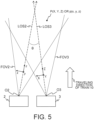
- FIG. 5 is a diagram for explaining deviation between a visual field of the camera 2 and a visual field of the ranging device 3.
- the camera 2 and the ranging device 3 are different in physical disposition, that is, view points and directions of the camera 2 and the ranging device 3 are different. Therefore, an origin 02, which is a view point, of a visual field FOV2 and a visual line LOS2 of the camera 2 and an origin 03, which is a view point, of a visual field FOV3 and a visual line LOS3 of the ranging device 3 are different from each other.
- a three-dimensional coordinate in the visual field FOV2 is referred to as xyz coordinate system (world coordinate system of the camera 2 or three-dimensional coordinate system of the camera 2) and a three-dimensional coordinate in the visual field FOV3 is referred to as XYZ coordinate system (world coordinate system of the ranging device 3 or three-dimensional coordinate system of the ranging device 3).
- xyz coordinate system world coordinate system of the camera 2 or three-dimensional coordinate system of the camera 2
- XYZ coordinate system world coordinate system of the ranging device 3 or three-dimensional coordinate system of the ranging device 3.
- a 3D image represented by the XYZ coordinate system includes only a value of a range (a part) observed by the ranging device 3 and does not include a value of a range (a part) included in the visual field FOV3 but not observed by the ranging device 3.
- Expression (1) is an expression for matching the origin O3 and the visual line LOS3 of the visual field FOV3 of the ranging device 3 to the origin O2 and the visual line LOS2 of the visual field FOV2 of the camera 2. That is, Expression (1) is an expression for converting the point P (X, Y, Z) in the XYZ coordinate system into a point p (x, y, z) in the xyz coordinate system.
- a matrix R is a rotation matrix for rotating the visual field FOV3 by an angle ⁇ .
- a matrix tvec is a translation matrix for translating the visual field FOV3.
- the origin O2 and the visual line LOS2 of the visual field FOV2 and the origin O3 and the visual line LOS3 of the visual field FOV3 coincide. That is, the point P included in the 3D image represented by the XYZ coordinate system can be represented as the point P of the xyz coordinate system.
- x y z R X Y Z + tvec
- the projection image generator 44 converts the point p (x, y, z) in the 3D image represented by the xyz coordinate system into a point p' (u, v) in the uv coordinate system using Expressions (2) to (4).
- the projection image generator 44 performs normalization at a distance z in the depth direction using Expression (2) and converts the point p included in the 3D image from a three-dimensional coordinate (an xyz coordinate system) into a two-dimensional coordinate (an x'y' coordinate system).
- x ′ y ′ 1 z x y
- the projection image generator 44 applies a distortion function f (x, y) specific to the camera 2 indicated by Expression (3).
- x " , y " f x ′ , y ′
- a coordinate system after the distortion function application of Expression (3) described above or the x'y' coordinate system described above corresponds to a two-dimensional coordinate system or a camera coordinate system of the camera 2.
- the projection image generator 44 converts the coordinate system of Expression (3) is converted into the uv coordinate system (the image coordinate system of the camera 2) using a camera matrix K specific to the camera 2.
- the camera matrix K is a 2 ⁇ 3 matrix.
- projection image an image formed by converting the 3D image into the uv coordinate system of the camera 2 is obtained.
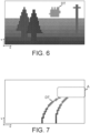
- FIG. 6 is a diagram illustrating an example of the 3D image projected onto the uv coordinate system.
- a pixel (a dot) DT corresponds to a position (an observation point) where one reflected pulse (reflected once) is received.
- the 3D image is represented as a set of a plurality of pixels DT (a point group). Three-dimensional positions and distance information of corresponding pixels of the 3D image before the conversion may be associated with pixels of the projection image.
- the distance from the train 10 is represented by light and shade of the pixel DT.
- a color of the pixel DT is shown lighter in a farther position from the train 10.
- Pixels without colors mean pixels that have not received the reflected pulse, that is, have not been successfully observed. In a position apart from the train 10 by a certain degree, since an incident angle of the pulse light emitted from the ranging device 3 with respect to the ground or the railroad track T increases, the pixels are more often not observed. Note that it is seen from FIGS. 3 and 6 that an object Obj3 is observed because the incident angle of the pulse light emitted from the ranging device 3 is small, although the object Obj3 is relatively apart from the train 10.
- the railroad track extractor 45 extracts, based on the railroad track image (see FIG. 4 ) and the projection image (see FIG. 6 ), in the projection image, an image of a railroad track portion corresponding to the railroad track T in the railroad track image.
- the extracted image of the railroad track portion is referred to as 3D railroad track.
- the railroad track extractor 45 superimposes the railroad track image and the projection image and extracts, as the 3D railroad track, a portion of the projection image overlapping the position of the railroad track T.
- a railroad track portion in the railroad track image overlapping the 3D railroad track corresponds to, in the railroad track T in the railroad track image, a railroad track portion where a portion corresponding thereto is present in the projection image.
- a region A illustrated in the figure is a region where a railroad track portion present in the railroad track image but absent in the projection image is present. That is, the region A is a region (a non-observed ) where the railroad track portion is not observed by the ranging device 3, although it is predicted from the railroad track image that the railroad track T is present. Note that the region A is a region where not the entire inside of the region A is not observed but at least the railroad track portion is not observed and is a region illustrated for reference to facilitate understanding.
- FIG. 8 illustrates a portion where the position of the railroad track T has been specified in the XYZ coordinate system. Consequently, concerning the portion where the position of the railroad track T has been specified, it is possible to calculate a construction limit of the railroad track T. Accordingly, it is possible to determine whether an obstacle (an object) in the XYZ coordinate system interferes with the construction limit.
- an obstacle an object
- the railroad track estimator 46 estimates a 3D railroad track in the region A. Note that the railroad track estimator 46 retains parameters concerning the camera 2 and parameters concerning the ranging device 3. The railroad track estimator 46 may use information concerning these parameters for the estimation. Processing performed by the railroad track estimator 46 is described in detail below.
- Estimation of a 3D railroad track in the XYZ coordinate system is described below.
- the 3D image acquired by the ranging device 3 has been converted into the uv coordinate system according to Expressions (1) to (4) described above.
- a method of estimating a 3D railroad track a method of converting the point p' (u, v) represented by the uv coordinate system into a XYZ coordinate system is described.
- the railroad track estimator 46 performs inverse conversion of Expression (4) using the following Expression (5).
- K[1:2, 1:2] means a 2 ⁇ 2 matrix on the left side of K and K[1:2, 3] means a column vector on the rightmost side of K.
- x " y " K 1 : 2,1 : 2 ⁇ 1 u v ⁇ K 1 : 2,3
- the railroad track estimator 46 performs inverse conversion of Expression (3) using an inverse function f -1 of the distortion function f shown in the following Expression (6).
- x ′ , y ′ f ⁇ 1 x " , y "
- z is represented as indicated by the following Expression (8). If a value of u and a value of v of the point p' are known, a value of x' and a value of y' are specified by Expressions (5) and (6). However, a value of z of the point p is unknown.
- Z 0 shown in Expression (8) represents a known value of a Z-axis coordinate of the point P in the XYZ coordinate system.
- a value of an X-axis coordinate or a value of a Y-axis coordinate of the point P may be known.
- a vector S -1 shown in Expression (8) is represented as indicated by the following Expression (9).
- R[3, 1:3] is a third row vector from the top of the rotation matrix R.
- the distance from the ranging device 3 to the point P may be known.
- the distance from a coordinate O3 (0, 0, 0) of the ranging device 3 to the point P (X, Y, Z) is represented as D
- X 2 +Y 2 +Z 2 D 2 .
- the following Expression (11) is obtained by substituting this in Expression (10).
- the distance from the camera 2 to the point p may be known.
- the distance from a coordinate O2 (0, 0, 0) of the camera 2 to the point p (x, y, z) is represented as d
- x 2 +y 2 +z 2 d 2 .
- the following Expression (12) is obtained by substituting this in Expression (7).
- the value of z of the point p needs to be known.
- additional information such as a coordinate of any axis in the XYZ coordinate system of the point P is necessary.
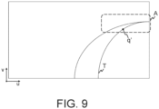
- FIG. 9 is a diagram illustrating a railroad track image for describing a method of estimating a position of a railroad track in the region A.
- a point q' corresponds to a point included in a range in which a portion corresponding to a projection image is absent in the railroad track of the railroad track image, that is, a point on the railroad track T in the region A on the railroad track image.
- This range (a range of a railroad track portion included in the region A) is set as a target range that is a base of estimation.
- a point in the three-dimensional coordinate system of the camera 2 corresponding to the point q' is represented as a point q.
- the point q' is information that is present on the railroad track image but is absent on a 3D image. It is conceived to estimate a point (a point Q (X, Y, Z)) in the XYZ coordinate system corresponding to the point q'.
- the railroad track estimator 46 includes, for example, a train position estimation function and a map database.
- the train position estimation function acquires a current position of the train 10 from a positioning system such as a GPS (Global Positioning System).
- the railroad track estimator 46 calculates, for example, the altitude of the train 10 from the current position of the train 10 and the map database.
- the railroad track estimator 46 acquires the position and the altitude of the railroad track T from the map database.
- the altitude is, for example, an elevation or a height above sea level.
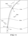
- FIG. 11 is a diagram in which the current position of the train 10, that is, the origin O3 in the XYZ coordinate system is displayed on a map acquired from the map database.
- contour lines indicating elevations 100 m, 105 m, and 110 m are displayed.
- the train 10 is illustrated to facilitate understanding.
- the epipolar line L is displayed on the map illustrated in FIG. 11 , it is seen that there is a point where the epipolar line L and the railroad track T cross (or intersect). This cross point (intersection) is estimated as the point Q. Note that, although a tilt in the height direction of the epipolar line L is seemed to be not considered in FIG. 11 , actually, the tilt in the height direction of the epipolar line L is also considered.
- a coordinate of the point Q in the XYZ coordinate system is (X 1 , 10 m, Z 1 ).
- X 1 and Z 1 are a value of an X coordinate and a value of a Z coordinate of the point Q made clear in a chain reaction manner because a value of a Y coordinate of the point Q has been made clear.
- the values of the XYZ coordinates of the point Q are estimated by estimating the value of the Y coordinate of the point Q from the map database. By repeating the processing described above, it is possible to estimate a position of the railroad track T in the region A in the XYZ coordinate system.
- the railroad track estimator 46 estimates a value or a distance of any one of the XYZ coordinates from the pixels DT around the pixel DT of the railroad track T. For example, although the point Q itself is not measured by the ranging device 3, as illustrated in FIG. 6 , for example, when the object Obj3 near the point Q is observed, the railroad track estimator 46 can estimate a value or a distance of any one of the XYZ coordinates of the point Q from an observed portion. Specifically, the railroad track estimator 46 specifies a railroad track portion not included in a 3D image (a railroad track portion corresponding to a 3D railroad track) in a railroad track included in a railroad track image.
- the railroad track estimator 46 detects, from the railroad track image, an object present close to the specified railroad track portion, a portion corresponding to the 3D image being included in the object.
- the railroad track estimator 46 estimates a three-dimensional position in the XYZ coordinate system of the railroad track portion corresponding to the 3D railroad track based on a three-dimensional position (a three-dimensional position in the three-dimensional coordinate system of the camera 2 or a three-dimensional position in the three-dimensional coordinate system of the ranging device 3) of the object.
- the railroad track estimator 46 estimates a three-dimensional position in the XYZ coordinate system of the railroad track portion corresponding to the 3D railroad track based on the distance from the view point of the camera 2 or the view point of the ranging device 3 to the object.
- the same Z coordinate as the Z coordinate of the object may be set as an estimation value.
- the railroad track estimator 46 estimates values of the XYZ coordinates of the point Q by, for example, estimating a distance from the origin O3 to the point Q from an observed point near the point Q.
- the railroad track estimator 46 estimates a distance from the camera 2 to the point q using the number of pixels corresponding to the width of the railroad track T in a forward image (a railroad track image). It is assumed that the width of the railroad track T is known and is fixed. Under this precondition, the railroad track estimator 46 can calculate a distance from the camera 2 to the point q based on the number of pixels corresponding to the width of the railroad track T in the forward image, an angle of view of the camera 2, and the number of pixels of the forward image.
- the railroad track estimator 46 can learn the position of the point q and convert a coordinate of the point q into a coordinate of the point Q in the XYZ coordinate system using Expression (12). Consequently, the railroad track estimator 46 can estimate a position of the railroad track T in the region A. As described above, in the third estimation method, by estimating the distance d from the point q to the origin O2 in the xyz coordinate system, the railroad track estimator 46 estimates values of the XYZ coordinates of the point Q using the number of pixels corresponding to the width of the railroad track T in the forward image.
- the camera 2 is a stereo camera and the railroad track estimator 46 estimates a distance from the camera 2 to the point q.
- the railroad track estimator 46 estimates a distance from the camera 2 to the point q from a parallax between the first forward image and the second forward image obtained by imaging the point q. If the distance from the camera 2 to the point q is known, a coordinate of the point Q in the XYZ coordinate system is specified using Expression (12), and the railroad track estimator 46 can estimate, in the XYZ coordinate system, the railroad track T in the region A.
- the railroad track estimator 46 estimates values of the XYZ coordinates of the point Q by estimating the distance d from the point q to the origin O2 in the xyz coordinate system using the stereo camera.
- the position of the railroad track T is specified and estimated in the XYZ coordinate system.
- the position of the railroad track T may be estimated in the xyz coordinate system.
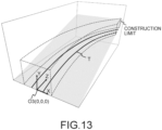
- the obstacle detector 47 calculates a construction limit from the railroad track estimated by the railroad track estimator 46 and the railroad track extracted by the railroad track extractor 45 and determines whether an object (an obstacle) that can be obstructive to traveling of the train 10 is present within the construction limit.
- FIG. 13 is a diagram illustrating the construction limit calculated based on the estimated and extracted railroad tracks.
- the construction limit specifies a range in which buildings should not be installed over the railroad track T.
- the obstacle detector 47 outputs a result of determining whether an object that can be obstructive to traveling is present within the construction limit. For example, when an object such as a large animal is detected within the construction limit, the obstacle detector 47 may determine that an object that can be obstructive to traveling is present. The obstacle detector 47 may output a determination result to a display visually recognizable by an operator of the train 10 or may output the determination result to an autonomous driving system of the train 10. The obstacle detector 47 may output the determination result only when determining that an obstructive object is present within the construction limit or may output the determination result irrespective of the determination result.
- the obstacle detector 47 may set a range wider than the construction limit and determine whether an obstructive object is present within the range. Consequently, for example, the operator can recognize a human present near the construction limit, although not entering the construction limit, and can take measures such as sounding a horn according to a situation.
- FIG. 14 is a flowchart of an example of processing performed by the obstacle detection system 1. The processing performed by the obstacle detection system 1 is described below with reference to FIG. 14 and the figures.
- the camera 2 captures an image (the forward image: see FIG. 3 ) of a forward environment of the train 10 (step S1).
- the captured forward image is taken into the obstacle detection device 4 by the image acquirer 41.
- the railroad track detector 42 detects the position of the railroad track T from the forward image, and acquires the railroad track image that extracts the railroad track T in the forward image (see FIG. 4 ) (step S2).
- the ranging device 3 acquires a 3D image of the forward environment of the train 10 (step S3).
- the acquired 3D image is taken into the obstacle detection device 4 by the 3D data acquirer 43.
- the projection image generator 44 projects the 3D image onto the railroad track image and acquires the projection image (see FIG. 6 ) (step S4).
- the railroad track extractor 45 extracts, based on the railroad track image (see FIG. 4 ) and the projection image (see FIG. 6 ), from the projection image, a portion (the 3D railroad track: see FIG. 7 ) corresponding to the railroad track T included in the railroad track image (step S5).
- the railroad track estimator 46 estimates, based on the extracted 3D railroad track and the railroad track image, in the XYZ coordinate, a railroad track portion that is included in the railroad track image but is not measured by the ranging device 3 (step S6).
- the obstacle detector 47 calculates a construction limit from the railroad track portion estimated in the XYZ coordinate system and the 3D railroad track (step S7).
- the obstacle detector 47 determines whether an obstacle is present within the calculated construction limit (step S8). For example, when an object equal to or larger than a predetermined size is present, the obstacle detector 47 may determine that an obstacle is present. Alternatively, the obstacle detector 47 may discriminate, using the railroad track image and semantic segmentation, a type of the object detected within the construction limit and, when the type of the object corresponds to a predetermined type of an obstacle, determine that an obstacle is present.
- the obstacle detector 47 outputs a determination result (step S9).
- the obstacle detector 47 outputs the determination result to, for example, the autonomous driving system of the train 10.
- step S8 ends, the processing returns to steps S1 and S3 and the steps are sequentially repeated. Note that the steps may be performed in parallel to the other steps. For example, the camera 2 may continue to capture the forward image even while the image acquirer 41 is acquiring the forward image in step S2.
- the ranging device 3 and the camera 2 are combined to estimate a position of a railroad track in a range in which ranging cannot be performed by the ranging device 3. This makes it possible to detect an obstacle even at a far distance at which measurement cannot be performed by the ranging device 3. This makes it possible to improve detection accuracy of a distance at which the obstacle can be detected and detection accuracy of the obstacle.
- the camera 2 and the ranging device 3 are the separate devices.
- the camera 2 and the ranging device 3 may be an integral device.
- the projection image generator 44 may be omitted.
- a 3D image of the ranging device 3 may be directly used instead of a projection image.
- the obstacle detection device 4 may be associated with a brake control system of a train.
- the brake control system may perform brake control for a car according to a determination result output by the obstacle detection device 4. For example, when an obstructive object is detected, control for stopping the train in a position before the position of the detected object may be performed.
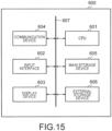
- FIG. 16 illustrates a hardware configuration of the information processing device according to each approach.
- the information processing device is configured as a computer device 600.
- the computer device 600 includes a CPU 601, an input interface 602, a display device 603, a communication device 604, a main storage device 605, and an external storage device 606, and these components are mutually connected through a bus 607.
- the CPU (central processing unit) 601 executes an information processing program as a computer program on the main storage device 605.
- the information processing program is a computer program configured to achieve each above-described functional composition of the present device.
- the information processing program may be achieved by a combination of a plurality of computer programs and scripts instead of one computer program.
- Each functional composition is achieved as the CPU 601 executes the information processing program.
- the input interface 602 is a circuit for inputting, to the present device, an operation signal from an input device such as a keyboard, a mouse, or a touch panel.
- the input interface 602 corresponds to the input device in each approach.
- the display device 603 displays data output from the present device.
- the display device 603 is, for example, a liquid crystal display (LCD), an organic electroluminescence display, a cathode-ray tube (CRT), or a plasma display (PDP) but is not limited thereto.
- Data output from the computer device 600 can be displayed on the display device 603.
- the display device 603 corresponds to the output device in each approach.
- the communication device 604 is a circuit for the present device to communicate with an external device in a wireless or wired manner. Data can be input from the external device through the communication device 604. The data input from the external device can be stored in the main storage device 605 or the external storage device 606.
- the main storage device 605 stores, for example, the information processing program, data necessary for execution of the information processing program, and data generated through execution of the information processing program.
- the information processing program is loaded and executed on the main storage device 605.
- the main storage device 605 is, for example, a RAM, a DRAM, or an SRAM but is not limited thereto. Each storage or database in the information processing device in each approach may be implemented on the main storage device 605.
- the external storage device 606 stores, for example, the information processing program, data necessary for execution of the information processing program, and data generated through execution of the information processing program.
- the information processing program and the data are read onto the main storage device 605 at execution of the information processing program.
- the external storage device 606 is, for example, a hard disk, an optical disk, a flash memory, or a magnetic tape but is not limited thereto.
- Each storage or database in the information processing device in each approach may be implemented on the external storage device 606.
- the information processing program may be installed on the computer device 600 in advance or may be stored in a storage medium such as a CD-ROM. Moreover, the information processing program in each approach may be uploaded on the Internet.
- the present device may be configured as a single computer device 600 or may be configured as a system including a plurality of mutually connected computer devices 600.
Landscapes
- Engineering & Computer Science (AREA)
- Physics & Mathematics (AREA)
- General Physics & Mathematics (AREA)
- Multimedia (AREA)
- Theoretical Computer Science (AREA)
- Mechanical Engineering (AREA)
- Train Traffic Observation, Control, And Security (AREA)
- Image Analysis (AREA)
Applications Claiming Priority (1)
| Application Number | Priority Date | Filing Date | Title |
|---|---|---|---|
| JP2023123790A JP2025019899A (ja) | 2023-07-28 | 2023-07-28 | 情報処理装置、情報処理システム、および情報処理方法 |
Publications (1)
| Publication Number | Publication Date |
|---|---|
| EP4497653A1 true EP4497653A1 (de) | 2025-01-29 |
Family
ID=90105231
Family Applications (1)
| Application Number | Title | Priority Date | Filing Date |
|---|---|---|---|
| EP24160333.1A Pending EP4497653A1 (de) | 2023-07-28 | 2024-02-28 | Informationsverarbeitungsvorrichtung und informationsverarbeitungsverfahren zur schätzung der dreidimensionalen lage eines eisenbahngleises |
Country Status (2)
| Country | Link |
|---|---|
| EP (1) | EP4497653A1 (de) |
| JP (1) | JP2025019899A (de) |
Families Citing this family (1)
| Publication number | Priority date | Publication date | Assignee | Title |
|---|---|---|---|---|
| JP7821932B1 (ja) * | 2025-07-10 | 2026-02-27 | 株式会社Jr東日本情報システム | シミュレーション装置、シミュレーションシステム、シミュレーション方法及びシミュレーションプログラム |
Citations (4)
| Publication number | Priority date | Publication date | Assignee | Title |
|---|---|---|---|---|
| EP1780675A1 (de) * | 2004-08-11 | 2007-05-02 | Tokyo Institute of Technology | Objektdetektor |
| US20180012085A1 (en) * | 2016-07-07 | 2018-01-11 | Ants Technology (Hk) Limited. | Computer Vision Based Driver Assistance Devices, Systems, Methods and Associated Computer Executable Code |
| EP3705371A1 (de) * | 2017-11-02 | 2020-09-09 | Kabushiki Kaisha Toshiba | Hindernisdetektor |
| EP3829155A1 (de) * | 2018-07-24 | 2021-06-02 | Kabushiki Kaisha Toshiba | Bilderzeugungssystem für eisenbahnfahrzeug |
Family Cites Families (2)
| Publication number | Priority date | Publication date | Assignee | Title |
|---|---|---|---|---|
| US20190039633A1 (en) * | 2017-08-02 | 2019-02-07 | Panton, Inc. | Railroad track anomaly detection |
| WO2019155569A1 (ja) * | 2018-02-08 | 2019-08-15 | 三菱電機株式会社 | 障害物検出装置および障害物検出方法 |
-
2023
- 2023-07-28 JP JP2023123790A patent/JP2025019899A/ja active Pending
-
2024
- 2024-02-28 EP EP24160333.1A patent/EP4497653A1/de active Pending
Patent Citations (4)
| Publication number | Priority date | Publication date | Assignee | Title |
|---|---|---|---|---|
| EP1780675A1 (de) * | 2004-08-11 | 2007-05-02 | Tokyo Institute of Technology | Objektdetektor |
| US20180012085A1 (en) * | 2016-07-07 | 2018-01-11 | Ants Technology (Hk) Limited. | Computer Vision Based Driver Assistance Devices, Systems, Methods and Associated Computer Executable Code |
| EP3705371A1 (de) * | 2017-11-02 | 2020-09-09 | Kabushiki Kaisha Toshiba | Hindernisdetektor |
| EP3829155A1 (de) * | 2018-07-24 | 2021-06-02 | Kabushiki Kaisha Toshiba | Bilderzeugungssystem für eisenbahnfahrzeug |
Also Published As
| Publication number | Publication date |
|---|---|
| JP2025019899A (ja) | 2025-02-07 |
Similar Documents
| Publication | Publication Date | Title |
|---|---|---|
| EP3662446B1 (de) | Erzeugung einer umgebungskarte um ein mobiles objekt mit hoher genauigkeit | |
| US11250288B2 (en) | Information processing apparatus and information processing method using correlation between attributes | |
| US10024965B2 (en) | Generating 3-dimensional maps of a scene using passive and active measurements | |
| JP7073315B2 (ja) | 乗物、乗物測位システム、及び乗物測位方法 | |
| CN110909705B (zh) | 一种基于车载摄像头的路侧停车位感知方法及系统 | |
| US8564657B2 (en) | Object motion detection system based on combining 3D warping techniques and a proper object motion detection | |
| US10501059B2 (en) | Stereo camera device | |
| EP2209091B1 (de) | System und Verfahren zur Objektbewegungsdetektion auf Grundlage von mehrfachem 3D-Warping und mit solch einem System ausgestattetes Fahrzeug | |
| CN108692719B (zh) | 物体检测装置 | |
| US11204610B2 (en) | Information processing apparatus, vehicle, and information processing method using correlation between attributes | |
| US20150356357A1 (en) | A method of detecting structural parts of a scene | |
| US20220067973A1 (en) | Camera calibration apparatus and operating method | |
| CN110341621B (zh) | 一种障碍物检测方法及装置 | |
| US20220207897A1 (en) | Systems and methods for automatic labeling of objects in 3d point clouds | |
| KR102117313B1 (ko) | 그래디언트 추정 장치, 그래디언트 추정 방법, 컴퓨터 프로그램 및 제어 시스템 | |
| JP4344860B2 (ja) | ステレオ画像を用いた道路平面領域並びに障害物検出方法 | |
| KR20100066952A (ko) | 스테레오 비전을 이용하여 장애물을 추적하는 장치 및 방법 | |
| Shan et al. | Probabilistic egocentric motion correction of lidar point cloud and projection to camera images for moving platforms | |
| KR101868898B1 (ko) | 자율주행을 위한 차선 인식 방법 및 장치 | |
| JP2025019899A (ja) | 情報処理装置、情報処理システム、および情報処理方法 | |
| CN118968468A (zh) | 用于车载视频处理系统的障碍物尺寸识别方法及相关设备 | |
| EP4498119A1 (de) | Entfernungsmessungsunterstützungsvorrichtung, entfernungsmessungssystem und entfernungsmessungsunterstützungsverfahren | |
| EP3916621B1 (de) | Verfahren und diagnoseeinheit zur beurteilung der zuverlässigkeit einer objektdetektionseinheit | |
| EP4435739A1 (de) | Verfahren und system zur zuordnung von umgebungswahrnehmungsdaten mit reibungszustandsinformationen, computerprogramm, computerlesbares speichermedium | |
| CN116166016A (zh) | 车载隧道衬砌检测装置的实时避障方法及装置 |
Legal Events
| Date | Code | Title | Description |
|---|---|---|---|
| PUAI | Public reference made under article 153(3) epc to a published international application that has entered the european phase |
Free format text: ORIGINAL CODE: 0009012 |
|
| STAA | Information on the status of an ep patent application or granted ep patent |
Free format text: STATUS: REQUEST FOR EXAMINATION WAS MADE |
|
| 17P | Request for examination filed |
Effective date: 20240228 |
|
| AK | Designated contracting states |
Kind code of ref document: A1 Designated state(s): AL AT BE BG CH CY CZ DE DK EE ES FI FR GB GR HR HU IE IS IT LI LT LU LV MC ME MK MT NL NO PL PT RO RS SE SI SK SM TR |