EP4497609A1 - Pneumatic tire - Google Patents
Pneumatic tire Download PDFInfo
- Publication number
- EP4497609A1 EP4497609A1 EP24187921.2A EP24187921A EP4497609A1 EP 4497609 A1 EP4497609 A1 EP 4497609A1 EP 24187921 A EP24187921 A EP 24187921A EP 4497609 A1 EP4497609 A1 EP 4497609A1
- Authority
- EP
- European Patent Office
- Prior art keywords
- tire
- sipe
- shoulder
- block
- central
- Prior art date
- Legal status (The legal status is an assumption and is not a legal conclusion. Google has not performed a legal analysis and makes no representation as to the accuracy of the status listed.)
- Granted
Links
Images


Classifications
-
- B—PERFORMING OPERATIONS; TRANSPORTING
- B60—VEHICLES IN GENERAL
- B60C—VEHICLE TYRES; TYRE INFLATION; TYRE CHANGING; CONNECTING VALVES TO INFLATABLE ELASTIC BODIES IN GENERAL; DEVICES OR ARRANGEMENTS RELATED TO TYRES
- B60C11/00—Tyre tread bands; Tread patterns; Anti-skid inserts
- B60C11/03—Tread patterns
- B60C11/0302—Tread patterns directional pattern, i.e. with main rolling direction
-
- B—PERFORMING OPERATIONS; TRANSPORTING
- B60—VEHICLES IN GENERAL
- B60C—VEHICLE TYRES; TYRE INFLATION; TYRE CHANGING; CONNECTING VALVES TO INFLATABLE ELASTIC BODIES IN GENERAL; DEVICES OR ARRANGEMENTS RELATED TO TYRES
- B60C11/00—Tyre tread bands; Tread patterns; Anti-skid inserts
- B60C11/03—Tread patterns
- B60C11/12—Tread patterns characterised by the use of narrow slits or incisions, e.g. sipes
- B60C11/1204—Tread patterns characterised by the use of narrow slits or incisions, e.g. sipes with special shape of the sipe
-
- B—PERFORMING OPERATIONS; TRANSPORTING
- B60—VEHICLES IN GENERAL
- B60C—VEHICLE TYRES; TYRE INFLATION; TYRE CHANGING; CONNECTING VALVES TO INFLATABLE ELASTIC BODIES IN GENERAL; DEVICES OR ARRANGEMENTS RELATED TO TYRES
- B60C11/00—Tyre tread bands; Tread patterns; Anti-skid inserts
- B60C11/03—Tread patterns
- B60C11/12—Tread patterns characterised by the use of narrow slits or incisions, e.g. sipes
- B60C11/1204—Tread patterns characterised by the use of narrow slits or incisions, e.g. sipes with special shape of the sipe
- B60C11/1218—Three-dimensional shape with regard to depth and extending direction
-
- B—PERFORMING OPERATIONS; TRANSPORTING
- B60—VEHICLES IN GENERAL
- B60C—VEHICLE TYRES; TYRE INFLATION; TYRE CHANGING; CONNECTING VALVES TO INFLATABLE ELASTIC BODIES IN GENERAL; DEVICES OR ARRANGEMENTS RELATED TO TYRES
- B60C11/00—Tyre tread bands; Tread patterns; Anti-skid inserts
- B60C11/03—Tread patterns
- B60C11/12—Tread patterns characterised by the use of narrow slits or incisions, e.g. sipes
- B60C11/1259—Depth of the sipe
- B60C11/1263—Depth of the sipe different within the same sipe
-
- B—PERFORMING OPERATIONS; TRANSPORTING
- B60—VEHICLES IN GENERAL
- B60C—VEHICLE TYRES; TYRE INFLATION; TYRE CHANGING; CONNECTING VALVES TO INFLATABLE ELASTIC BODIES IN GENERAL; DEVICES OR ARRANGEMENTS RELATED TO TYRES
- B60C11/00—Tyre tread bands; Tread patterns; Anti-skid inserts
- B60C11/03—Tread patterns
- B60C11/12—Tread patterns characterised by the use of narrow slits or incisions, e.g. sipes
- B60C11/1204—Tread patterns characterised by the use of narrow slits or incisions, e.g. sipes with special shape of the sipe
- B60C2011/1213—Tread patterns characterised by the use of narrow slits or incisions, e.g. sipes with special shape of the sipe sinusoidal or zigzag at the tread surface
Definitions
- the present invention relates to a pneumatic tire.
- a tire which includes a tread including a tread surface which contacts the road surface.
- This tread has a so-called block pattern in which a plurality of blocks are defined by a plurality of grooves extending in the tire-circumferential direction or in a direction intersecting the tire-circumferential direction.
- the blocks are arranged in the tire-circumferential direction.
- Patent Document 1 discloses a pneumatic tire in which a plurality of thin grooves called sipes are formed in such a block.
- Sipes have a wavy shape in a tire surface view. For example, wavy shaped sipes having a large amplitude are considered useful in improving the tire grip performance when traveling on snowy roads.
- Patent Document 1 Japanese Unexamined Patent Application, Publication No. H11-310013
- the contact pressure on the blocks arranged in the region of the shoulders on both sides in the tire-axial direction of the tread tends to increase; particularly, an area around the sipe of the wavy shape having a large amplitude tends to be subject to great pressure. For this reason, defects such as local wear and block chipping around the sipes may arise, and thus there is room for improvement.
- the shoulder blocks have a great effect on the running stability on snowy road surfaces.
- the present invention has an object of providing a pneumatic tire for which blocks arranged in the region of the shoulder are unlikely to be damaged, and thus running stability on snowy road surfaces can be secured.
- a pneumatic tire according to an aspect of the present invention includes a tread.
- the tread includes a plurality of blocks arranged in the tire-circumferential direction.
- the plurality of blocks includes a plurality of shoulder blocks arranged in an outermost area in the tire-axial direction, a plurality of central blocks arranged at the center in the tire-axial direction, and a plurality of intermediate blocks arranged between the shoulder blocks and the central blocks in the tire-axial direction.
- the shoulder block has at least one shoulder sipe having a wavy shape in a tire surface view, and extending in a direction which intersects the tire-circumferential direction.
- the central block has at least one central sipe having a wavy shape in a tire surface view and extending in the direction which intersects the tire-circumferential direction.
- the intermediate block has at least one intermediate sipe having a wavy shape in a tire surface view, and extending in the direction which intersects the tire-circumferential direction.
- a relationship of CeA ⁇ MeA > ShA is established where ShA is amplitude in a tire surface of the shoulder sipe, CeA is amplitude in a tire surface of the central sipe, and MeA is amplitude in a tire surface of the intermediate sipe as MeA.
- the present invention makes it possible to provide a pneumatic tire for which blocks arranged in the region of the shoulder are unlikely to be damaged, and thus running stability on snowy road surfaces can be secured.
- FIG. 1 is a view expanding a part of the outer circumferential surface of a tire 1 in a plan view, the tire 1 being a pneumatic tire according to the embodiment.
- the tire 1 according to the embodiment can be applied to a tire for passenger vehicles; however, besides this, it can be also applied to a tire for various vehicles such as light trucks, trucks and buses
- FIG. 1 shows a tire-axial direction X and a tire-circumferential direction C.
- one side of the tire-circumferential direction is defined as a rotational direction during forward advancement of the vehicle on which the tire 1 is mounted, and C1 direction shown in FIG. 1 corresponds to this rotational direction.
- the front side referred to in the following description corresponds to the right side of FIG. 1 , and indicates a side in the advancing direction of the vehicle defined as the tire rotation direction C1.
- the rear side corresponds to the left side in FIG. 1 , and indicates the reverse direction of the vehicle defined as the rotation direction C2 which is the opposite direction to the tire rotation direction C1.
- FIG. 1 shows the tread 10 of the tire 1, and shoulders 30 on both tire-axial sides of the tread 10.
- the shoulder 30 is a portion transitioning from the tread 10 to each of the sidewalls (not shown) on both sides in the tire axial direction, and is a portion corresponding to the shoulder of the tire 1.
- the shoulder 30 includes a first shoulder 31 on the upper side in FIG. 1 , and a second shoulder 32 on the lower side in FIG. 1 .
- the tread 10 has a tread surface 20 to be in contact with the road surface.
- a tread pattern 11 is formed on the tread surface 20.
- the tread pattern 11 is mainly designed by a plurality of grooves 12, and a plurality of blocks 13 defined by the grooves 12.
- FIG. 1 shows a tire equatorial plane S1, which corresponds to a virtual line extending at the tire-axial center of the tread surface 20 along the tire circumferential direction.
- the tread pattern 11 When defining the tire axial direction as the left/right direction, the tread pattern 11 is substantially left/right symmetrical with the tire equatorial plane S1 as the symmetrical line, except that the tread pattern 11 is somewhat displaced in the tire circumferential direction.
- the tread surface 20 includes a first tread surface 21 close to the first shoulder 31, and a second tread surface 22 close to the second shoulder 32, with the tire equatorial plane S1 as a boundary.
- the grooves 12 of the tread pattern 11 include a plurality of slanted grooves 40, and a plurality of communication grooves 50.
- the slanted grooves 40 and the communication grooves 50 according to the embodiment are grooves having a groove width exceeding 1 mm.
- the slanted grooves 40 are grooves extending from both tire-axial sides toward the tire equatorial plane S1. These slanted grooves 40 are arranged at intervals in the tire-circumferential direction.
- the plurality of slanted grooves 40 includes first slanted grooves 41 extending from the first shoulder 31 toward the tire equatorial plane S1, and second slanted grooves 42 extending from the second shoulder 32 toward the tire equatorial plane S1.
- the first slanted groove 41 is formed mainly on the first tread surface 21, and the second sloped groove 42 is mainly formed on the second tread surface 22.
- the communication grooves 50 include first communication grooves 51 and second communication grooves 52. Each of the first communication groove 51 communicates with a pair of first slanted grooves 41 adjacent in the tire-circumferential direction. Each of the second communication groove 52 communicates with a pair of second slanted grooves 42 adjacent in the tire-circumferential direction.
- the first communication grooves 51 are formed in the first tread surface 21, and the second communication groove 52 is formed in the second tread surface 22.
- the tread pattern 11 is left/right symmetrical, the first slanted grooves 41 and second slanted grooves 42 have similar features, and the first communication grooves 51 and second communication grooves 52 have similar features.
- the first slanted grooves 41 are grooves extending from the first shoulder 31 toward the tire equatorial plane S1, in which the slanted grooves 41 generally slope relative to the tire-circumferential direction while gradually curving so that the slanted grooves 41 extend toward the front side and is convex toward the rear side.
- the second slanted grooves 42 are grooves extending from the second shoulder 32 toward the tire equatorial plane S1, in which the slanted grooves 42 generally slope relative to the tire-circumferential direction while gradually curving so that the slanted grooves 42 extend toward the front side and is convex toward the rear side.
- each of the slanted grooves 41, 42 has an end close to the shoulder 30 (first shoulder 31, second shoulder 32) defined as a base end, and an end close to the tire equatorial plane S1 defined as a leading end.
- the first slanted groove 41 includes a base-end side curved part 43 and a leading-end side curved part 44.
- the base-end side curved part 43 extends from the base end to a portion beyond the tire-width center of the first tread surface 21.
- the leading-end side curved part 44 which curves from an end close to the tire equatorial plane S1 of the base-end side curved part 43 toward the tire equatorial plane S1 and to the leading end.
- the base-end side curved part 43 curves with a relatively small curvature, and is slightly sloped toward the front side.
- the leading-end side curved part 44 curves with a similar curvature to the base-end side curved part 43, and slopes to the front side at a sharper angle than the base-end side curved part 43.
- the second slanted groove 42 has a similar form to the first slanted groove 41.
- the second slanted groove 42 includes a based-end curved part 43 and a leading-end side curved part 44.
- the base-end curved part 43 extends from the base end to a portion beyond the tire-width center of the second tread surface 22.
- the leading-end side curved part 44 curves from an end close to the tire equatorial plane S1 of the base-end side curved part 43 toward the tire equatorial plane S1 to the leading end.
- the plurality of first slanted grooves 41 arranged in the tire-circumferential direction have alternately different lengths.
- the leading end of the shorter first slanted grooves 41 terminates such that it merges with the second slanted groove 42 immediately before the tire equatorial plane S1.
- the leading end of the longer first slanted groove 41 passes through the tire equatorial plane S1, and then terminates after crossing the leading-end side curved part 44 of the two second slanted grooves 42 adjacent in the tire-circumferential direction.
- the length of the second slanted grooves 42 also differ alternately in the tire-circumferential direction similarly to the first slanted grooves 41.
- the leading end of the shorter second slanted groove 42 terminates such that it merges with the first slanted groove 41 immediately before the tire equatorial plane S1.
- the leading end of the longer second slanted groove 42 passes through the tire equatorial plane S1, and then terminates after crossing the leading-end side curved part 44 of the two first slanted grooves 41 adjacent in the tire-circumferential direction.
- the first communication groove 51 extends from the end of the leading-end side curved part 44 of the first slanted groove 41 close to the base-end side curved part 43, straight toward a bending point of the first slanted groove 41 on the front side in the tire-circumferential direction.
- the bending point is a point where the first slanted groove 41 transitions from the base-end side curved part 43 to the leading-end side curved part 44.
- the second communication groove 52 is similar to the first communication groove 51, and extends from the end of the leading-end side curved part 44 of the second sloped groove 42 close to the base-end side curved part 43, straight to a bending point of the second slanted groove 42 on the front side in the tire-circumferential direction.
- the bending point is a point where the second sloped groove 42 transitions from the base-end side curved part 43 to the leading-end side curved part 44.
- the first communication groove 51 and second communication groove 52 both slope relative to the tire-circumferential direction so as to be directed toward the outer side in the tire-circumferential direction, as extending from the rear side to the front side.
- the blocks 13 of the tread pattern 11 include a plurality of shoulder blocks 60 arranged in the outermost positions in the tire-axial direction, a plurality of central blocks 70 arranged at the center in the tire-axial direction, and a plurality of intermediate blocks 80 arranged between the should blocks 60 and the central blocks 70 in the tire-axial direction.
- the shoulder blocks 60 include first shoulder blocks 61 close to the first shoulder 31, and second shoulder blocks 62 close to the second shoulder 32.
- Each of the first shoulder blocks 61 are defined as an approximately rectangular shapes by a pair of first slanted grooves 41 adjacent in the tire-circumferential direction, and the first communication groove 51.
- the edge of the first shoulder block 61 close to the first shoulder 31 continues to the outer surface of the first shoulder 31.
- the plurality of first shoulder blocks 61 are arranged in the tire-circumferential direction to sandwich the base-end side curved part 43 of the first slanted groove 41.
- Each of the second shoulder blocks 62 is defined as approximately rectangular shape, by the pair of the second slanted grooves 42 adjacent in the tire-circumferential direction, and the second communication groove 52.
- the edge of the second shoulder block 62 close to the second shoulder 32 continues to the outer surface of the second shoulder 32.
- the plurality of second shoulder blocks 62 are arranged in the tire-circumferential direction to sandwich the base-end side curved parts 43 of the second slanted grooves 42.
- the first shoulder blocks 61 and the second shoulder blocks 62 which are arranged in the tire-circumferential direction to sandwich the base-end side curved parts 43 of the slanted grooves 40, may be arranged at equal intervals in the tire-circumferential direction, or may be arranged at variable pitch, which are irregular intervals.
- the central blocks 70 are arranged in a manner such that they span both the first tread surface 21 and second tread surface 22. In other words, the tire equatorial plane S1 passes through all of the central blocks 70.
- the plurality of central blocks 70 includes a plurality of first central blocks 71 existing mainly on the first tread surface 21, and a plurality of second central blocks 72 existing mainly on the second tread surface 22.
- the first central block 71 has a larger proportion occupying the surface area in the first tread surface 21 than in the second tread surface 22.
- Each of the first central blocks 71 is defined as a substantially rectangular shape by the leading-end side curved parts 44 of the pair of first slanted grooves 41 adjacent in the tire-circumferential direction, and the leading-end side curved part 44 of the second slanted groove 42 having a greater length among the plurality of second slanted grooves 42.
- the second central block 72 has a greater proportion occupying the surface area in the second tread surface 22 than in the first tread surface 21.
- Each of the second central blocks 72 is defined as a substantially rectangular shape, by the leading-end side curved parts 44 of the pair of second slanted grooves 42 adjacent in the tire-circumferential direction, and the leading-end side curved part 44 of the first slanted groove 41 having a larger length among the plurality of first slanted grooves 41.
- the plurality of the first central blocks 71 and the plurality of second central blocks 72 are alternately arranged in the tire-circumferential direction.
- the intermediate block 80 includes a first intermediate block 81 close to the first tread surface 21, and a second intermediate block 82 close to the second tread surface 22.
- Each of the first intermediate block 81 is defined as an approximately rectangular shape by the leading-end side curved parts 44 of the pair of first slanted grooves 41 adjacent in the tire-circumferential direction, the first communication groove 51, and the leading-end side curved part 44 of the second slanted groove 42 having a longer length.
- the plurality of first intermediate blocks 81 are arranged in the tire-circumferential direction to sandwich the leading-end side curved part 44 of the first slanted groove 41.
- Each of the second intermediate block 82 is defined as an approximately rectangular shape by the leading-end side curved parts 44 of the pair of second slanted grooves 42 adjacent in the tire-circumferential direction, the second communication groove 52, and the leading-end side curved part 44 of the second slanted groove 42 having a longer length.
- the plurality of second intermediate blocks 82 are arranged in the tire-circumferential direction to sandwich the leading-end side curved part 44 of the second slanted groove 42.
- the first intermediate blocks 81 are arranged between the shoulder blocks 60 and the central blocks 70 in the tire-axial direction.
- the second intermediate blocks 82 are arranged between the shoulder blocks 60 and the central blocks 70 in the tire-axial direction.
- the tire equatorial plane S1 passes through all of the central blocks 70. On the other hand, the tire equatorial plane S1 neither passes through the shoulder blocks 60 nor the intermediate blocks 80.
- the block column 13A includes, as the three blocks 13, the first shoulder block 61, the first intermediate block 81, and the first central block 71 that extend in this order from the first shoulder 31 toward the tire equatorial plane S1.
- the block column 13B includes, as the two blocks 13, the first shoulder block 61 and the first intermediate block 81 that extend in this order from the first shoulder 31 toward the tire equatorial plane S1.
- the block column 13A includes, as the three blocks 13, the second shoulder block 62, the second intermediate block 82, and the second central block 72 that extend in this order from the second shoulder 32 toward the tire equatorial plane S1.
- the block column 13B includes, as the two blocks 13, the second shoulder block 62 and second intermediate block 82 that extend in this order.
- the intermediate block 80 in the column without the central block 70 has a longer length in the extending direction along the slanted groove 40, than the intermediate block 80 in the column with the central block 70.
- the shoulder block 60 and the central block 70 have the equal length in the extending direction along the slanted groove 40.
- each of the blocks 13 of the tread 10 has a plurality of sipes 14.
- the plurality of sipes 14 includes shoulder sipes 110, central sipes 120, and intermediate sipes 130.
- the shoulder sipes 110 are respectively formed in the first shoulder blocks 61 and the second shoulder blocks 62 (hereinafter, may be collectively called “shoulder block 60").
- the central sipes 120 are respectively formed in the first central blocks 71 and the second central blocks 72 (hereinafter, may be collectively called “central block 70")
- the intermediate sipes 130 are respectively formed in the first intermediate blocks 81 and the second intermediate blocks 82 (hereinafter, may be collectively called “intermediate block 80").
- All sipes have a smaller groove width than the aforementioned slanted grooves 40 and the communication grooves 50, and this groove width is no more than 1 mm.
- the number of the sipes 14 per each block 13 is arbitrary; however, sipes 14 of the number on the order of 2 to 5, for example, are arranged in one block 13.
- the shoulder sipes 110, the central sipes 120 and the intermediate sipes 130 respectively open in the surfaces of the blocks 60, 70, and 80, and have a wavy shape as a whole in a tire surface view.
- the depth direction of the sipes 110, 120, 130 substantially follows the tire-radial direction.
- each shoulder block 60 respectively has a plurality of shoulder sipes 110.
- the shoulder sipes 110 extend almost straight as a whole.
- the plurality of shoulder sipes 110 are arranged in parallel to each other at intervals.
- the plurality of shoulder sipes 110 extend substantially in parallel to the extending direction of the shoulder blocks 60 along the slanted groove 40. In other words, the shoulder sipes 110 extend in the direction intersecting the tire-circumferential direction.
- the end on the tire-axial inner side (tire equatorial plan S1 side) of the shoulder sipe 110 communicates with the first communication groove 51 and the second communication groove 52 (hereinafter, may be collectively called "communication groove 50").
- the end on the tire-axial outer side (shoulder 30 side) of the shoulder sipe 110 terminates without reaching the end on the tire-axial outer side of the shoulder block 60.
- FIG. 2 is a perspective view showing one shoulder sipe 110.
- FIG. 3A is an arrow view along IIIA-IIIA in FIG. 2 .
- FIG. 3B is a cross-sectional view along the line IIIB-IIIB in FIG. 2 .
- FIG. 3C is a cross-sectional view along the line IIIC-IIIC in FIG. 2 .
- FIG. 3D is a cross-sectional view along the line IIID-IIID in FIG. 2 .
- FIG. 4 is a cross-sectional view along the line IV-IV in FIG. 3A .
- the shoulder sipe 110 has a wavy-shaped part 113 and a sipe bridge 114.
- the wavy-shape part 113 is formed in a wavy shape extending along the extending direction.
- the sipe bridge 114 extends straight from an end of the wavy shaped part 113 to the communication groove 50, and has a smaller depth than that of the wavy shaped part 113.
- the shoulder sipe 110 has an opening 113A in the surface of the shoulder block 60, and a bottom 113B.
- the wavy shaped part 113 occupies a large portion, e.g., at least 70% of the extending direction length of the shoulder sipe 110.
- the depth of the wavy shaped part 113, a length between the opening 113A and the bottom 113B, is set on the order of 5.0 mm to 7.0 mm, for example, and the depth of the sipe bridge 114 is set on the order of 2.0 mm to 4.0 mm, for example; however, they are not limited thereto.
- the wavy shaped part 113 of the shoulder sipe 110 is formed in a wavy shape having a fixed period and the wavy shape extends from the opening 113A to the bottom 113B.
- the amplitude of the wavy shape part 113 is largest at the opening 113A, and smallest at the bottom 113B.
- the shoulder sipe 110 has a wavy shape at the bottom 113B, and the bottom 113B does not have a linear shape.
- the amplitudes of the openings 113A at the surfaces of the shoulder blocks 60 of the plurality of shoulder sipes 110 are equal to each other.
- the amplitude of the shoulder sipe 110 decreases at a fixed or constant rate of change from the opening 113A to the bottom 113B.
- the width of a gap between opposing inner surfaces of the shoulder sipe 110 has a substantially fixed dimension from the opening 113A to the bottom 113B. Accordingly, in a cross-sectional view in the depth direction which is substantially orthogonal to the extending direction of the shoulder sipe 110, as shown in FIG. 4 , the shoulder sipe 110 is linear from the opening 113A to the bottom 113B.
- the width of the shoulder sipe 110 is preferably at least 0.5 mm and no more than 1.5 mm.
- the shoulder sipe 110 of the present embodiment has a portion in which part of the wavy shape part 113 is not continuous in the extending direction, i.e., a part is missing, as shown in FIG. 2 and FIGS. 3B to 3D .
- the shoulder sipe 110 is not to be limited to this, and may have a continuous wave shape.
- each of the central blocks 70 has a plurality of central sipes 120.
- the central sipes 120 extend straight as a whole.
- the plurality of central sipes 120 are arranged in parallel to each other at intervals.
- the plurality of central sipes 120 extend substantially in parallel with the tire-axial direction. In other words, the central sipe 120 extends in a direction intersecting the tire-circumferential direction.
- Each of both ends of the central sipe 120 is continuous with either the first slanted groove 41 or the second slanted groove 42 (hereinafter, may be collectively called "slanted groove 40").
- FIG. 5 is a perspective view showing one central sipe 120.
- FIG. 6A is an arrow view along VIA-VIA in FIG. 5 .
- FIG. 6B is a cross-sectional view along the line VIB-VIB in FIG. 5 .
- FIG. 6C is a cross-sectional view along the line VIC-VIC in FIG. 5 .
- FIG. 6D is a cross-sectional view along the line VID-VID in FIG. 5 .
- FIG. 7 is a cross-sectional view along the line VII-VII in FIG. 6A .
- the central sipe 120 includes a wavy shape part 123, a first sipe bridge 121, and a second sipe bridge 122.
- the wavy shape part 123 is formed in a wavy shape along the extending direction.
- the first sipe bridge 121 extends straight from one end of the wavy shape part 123 to the slanted groove 40, and has a smaller depth than the wavy shape part 123.
- the second sipe bridge 122 extends straight from the other end of the wavy shape part 123 to the slanted groove 40, and has a smaller depth than the first sipe bridge 121.
- the central sipe 120 includes an opening 123A at the surface of the central block 70, and a bottom 123B.
- the wavy shape part 123 occupies at least 50%, for example, of the length in the extending direction of the central sipe 120.
- the depth of the wavy shape part 123 i.e., a length between the opening 123A and the bottom 123B is set on the order of 6.0 mm to 7.0 mm, for example, the depth of the first sipe bridge 121 is set on the order of 4 mm, for example, and the depth of the second sipe bridge 122 is set on the order of 2 mm, for example; however, they are not limited thereto.
- the wavy shape part 123 of the central sipe 120 is formed in a wavy shape having a fixed period, and the wave shape extends from the opening 123A to the bottom 123B.
- the amplitude of the wavy shape part 123 is largest at the opening 123A, and smallest at the bottom 123B.
- the central sipe 120 has amplitude at the bottom 123B, and the bottom 123B does not have a linear shape.
- the amplitudes of the openings 123A in the surfaces of the central blocks 70 of the plurality of central sipes 120 are equal to each other.
- the amplitude of the central sipe 120 decreases at a fixed rate of change from the opening 123A to the bottom 123B.
- the width of a gap between opposing inner surfaces of the central sipe 120 has a substantially fixed dimension from the opening 123A to the bottom 123B. Accordingly, in the cross-sectional view in the depth direction which is substantially orthogonal to the extending direction of the central sipe 120 as shown in FIG. 7 , the central sipe 120 is linear from the opening 123A to the bottom 123B.
- the width of the central sipe 120 is preferably at least 0.5 mm and no more than 1.5 mm.
- each of the intermediate blocks 80 has a plurality of intermediate sipes 130.
- the intermediate sipe 130 extends straight as a whole.
- the plurality of intermediate sipes 130 are arranged in parallel to each other at intervals.
- the plurality of intermediate sipes 130 all slant relative to the tire-circumferential direction so as to be directed to the outer side in the tire-circumferential direction, as extending from the rear side to the front side.
- the intermediate sipe 130 extends in a direction which intersects the tire-circumferential direction.
- Each of both ends of the intermediate sipe 130 communicate with either the slanted groove 40 or the communication groove 50.
- the intermediate sipe 130 has a similar configuration to the aforementioned central sipe 120.
- the intermediate sipe 130 has similar portions to the wavy shape part 123, the first sipe bridge 121, and the second sipe bridge 122 of the central sipe 120.
- the period of the wavy shape part of the intermediate sipe 130 is fixed, and the amplitude is largest at the opening at the surface of the central block 70, and smallest at the bottom.
- the amplitudes of the openings, at the surface of the intermediate blocks 80, of the plurality of intermediate sipes 130 are equal to each other.
- the width of the intermediate sipe 130 is substantially fixed from the opening to the bottom.
- the intermediate sipe 130 is linear from the opening to the bottom.
- the width of the intermediate sipe 130 is preferably at least 0.5 mm and no more than 1.5 mm.
- FIG. 8A is a plan view schematically showing an opening 113A of a wavy shape in the shoulder sipe 110, and shows amplitude ShA of the opening 113A.
- FIG. 8B is a plan view schematically showing a bottom 113B of a wavy shape in the shoulder sipe 110, and shows amplitude ShB of the bottom 113B.
- FIG. 9A is a plan view schematically showing an opening 123A of a wavy shape in the central sipe 120, and shows amplitude CeA of the opening 123A.
- FIG. 9B is a plan view schematically showing a bottom 123B of a wavy shape in the central sipe 120, and shows amplitude CeB of the bottom 123B.
- FIG. 10A is a plan view schematically showing an opening 133A of a wavy shape in the intermediate sipe 130, and shows amplitude MeA of the opening 133A.
- FIG. 10B is a plan view schematically showing a bottom 133B of a wavy shape in the intermediate sipe 130, and shows amplitude MeB of the bottom 133B.
- the above-mentioned amplitudes ShA, CeA and MeA are not equal.
- the amplitude ShA of the shoulder sipe 110 is the smallest.
- the amplitude CeA of the central sipe 120 and the amplitude MeA of the intermediate sipe 130 are equal to each other, or the amplitude CeA of the central sipe 120 is greater than the amplitude MeA of the intermediate sipe 130. In other words, it is specified as "CeA ⁇ MeA > ShA".
- these amplitudes CeA, MeA and ShA are preferably each at least 0.5 mm and no more than 1.5 mm.
- the amplitude ShB of the bottom 113B of the shoulder sipe 110, the amplitude CeB of the bottom 123B of the central sipe 120, and the amplitude MeB of the bottom 133B of the intermediate sipe 130 are preferably each at least 0.1 mm and no more than 0.6 mm.
- the ratio A/B for each sipe is preferably at least 4.0 and no more than 7.0, where A is the amplitudes of the openings 113A, 123A, 133A of the respective sipes 110, 120, 130, and B is the amplitudes of the bottoms 113B, 123B, 133B of the respective sipes 110, 120, 130.
- each of ShA/ShB of the shoulder sipe 110, CeA/CeB of the central sipe 120, and MeA/MeB of the intermediate sipe 130 is preferably at least 4.0 and no more than 7.0.
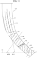
- FIG. 11 is a plan view shown by excerpting the block column 13A, consisting of the first shoulder block 61, the first central block 71, and the first intermediate block 81, which extends along the first slanted groove 41, in the first tread surface 21.
- FIG. 11 illustrates angles in the extending direction of each sipe relative to the tire equatorial plane S1 along the tire-circumferential direction.
- An angle in the extending direction of the shoulder sipe 110 is defined as Sh ⁇
- an angle of the extending direction of the central sipe 120 is defined as Ce ⁇
- an angle of the extending direction of the intermediate sipe 130 as Me ⁇ .
- These angles are all angles which intersect the tire equatorial plane S1 with an angle of at least 0° and no more than 90°. In the present embodiment, these angles are specified as "Ce ⁇ > Sh ⁇ > Me ⁇ ".
- the above-mentioned angle Ce ⁇ of the central sipe 120 is set at 90°, for example.
- the above-mentioned angle Sh ⁇ of the shoulder sipe 110 is set at 75°, for example.
- the above-mentioned angle Me ⁇ of the intermediate sipe 130 is set at 53°, for example. However, so long as satisfying the above specified ranges, they are not limited thereto.
- each of the plurality of sipes within the same block extends at the same angle relative to the tire equatorial plane S1.
- the above-mentioned angles Sh ⁇ of the plurality of shoulder sipes 110 in the same shoulder block 60 are the same angle as each other.
- the above-mentioned angles Ce ⁇ of the plurality of central sipes 120 in the same central block 70 are the same as each other.
- the above-mentioned angles Me ⁇ of the plurality of intermediate sipes 130 in the same intermediate block 80 are the same as each other.
- each of the sipes 14 in the present embodiment does not have a linear shape along the extending direction of the sipe 14, but rather has a wavy shape.
- both side portions on the sipe 14 of the block 13 tend to collapse according to the direction in which this stress acts.
- the bottom of the sipe 14 which has a wave shape as in the embodiment produces a force resisting stress and the forces is higher than that of the bottom of the sipe which has a a linear shape. This reduces the chances of distortion of the blocks 13, and the decline in contact area of the surface of the block 13. This improves the traction.
- distortion of the block 13 is suppressed, defects such as block chipping where a part or the entirety of the block 13 comes off is suppressed, whereby durability of the tire 1 improves.
- each of the sipes 14 of the present embodiment the amplitude decreasing at a fixed rate of change from the opening to the bottom in the surface of each block 13 allows each of the sipes 14 to be linear from the opening to the bottom, in a cross-sectional view in the depth direction which is substantially orthogonal to the extending direction of each sipe 14. Accordingly, the bottom of the sipe 14 functions as the aforementioned starting point for collapse of the block 13. In addition, since both the side portions of the sipe 14 of the block 13 tend to engage, the traction improves. The improvement in traction improves cornering performance and handling stability.
- the amplitude of the opening, which is at the surface of the block 13, of the sipe 14 is preferably at least 0.5 mm and no more than 1.5 mm.
- the amplitude of the bottom of the sipe 14 is preferably at least 0.1 mm and no more than 0.6 mm.
- a width of the sipe 14 is preferably at least 0.5 mm and no more than 1.5 mm.
- the ratio As/Ab is preferably at least 4.0 and no more than 7.0, where AS is amplitude of the opening at the surface of the block 13 of the sipe 14, and Ab is amplitude of the bottom of the sipe 14.
- the tire 1 includes a tread 10.
- the tread 10 includes a plurality of blocks 13 arranged in the tire-circumferential direction.
- the plurality of blocks 13 includes a plurality of shoulder blocks 60 arranged in an outermost area in the tire-axial direction, a plurality of central blocks 70 arranged at the center in the tire-axial direction, and a plurality of intermediate blocks 80 arranged between the shoulder blocks 60 and central blocks 70 in the tire-axial direction.
- the shoulder block 60 has at least one shoulder sipe 110 having a wavy shape in a tire surface view, and extending in a direction which intersects the tire-circumferential direction.
- the central block 70 has at least one central sipe 120 having a wavy shape in a tire surface view and extending in a direction which intersects the tire-circumferential direction.
- the intermediate block 80 has at least one intermediate sipe 130 having a wavy shape in a tire surface view, and extending in a direction which intersects the tire-circumferential direction.
- a relationship of CeA ⁇ MeA > ShA is established where Sha is an amplitude in a tire surface of the shoulder sipe 110, CeA is an amplitude in a tire surface of the central sipe 120, and MeA is amplitude in a tire surface of the intermediate sipe 130.
- the contact pressure on a block arranged in the region of the shoulder tends to increase, particularly, the area around the sipe, which has the wavy shape with a large amplitude, tends to be subject to great pressure.
- the amplitude in the tire surface of the shoulder sipe 110 of the shoulder block 60 is set to be smaller than that of the central sipe 120 of the central block 70 and that of the intermediate sipe 130 of the intermediate block 80. This disperses the contact pressure acting on the shoulder block 60, thus reducing the chances of distortion in both the side portions of the shoulder sipe 110. This further reduces the chances of defects such as localized wear and block chipping in the shoulder block 60. This suppressing of localized wear and block chipping enables running stability on a snowy road surface, because the shoulder block 60 contributes to running stability particularly on a snowy road surface.
- the intermediate block 80 largely affects running stability on dry road surfaces, and also affects the running stability on snowy road surfaces.
- the amplitude of the intermediate sipe 130 of the intermediate block 80 is greater than the amplitude of the shoulder sipe 110, and is equal to or smaller than the central sipe 120. This ensures running stability on both dry road surfaces and snowy road surfaces.
- the relationship of Ce ⁇ > Sh ⁇ > Me ⁇ is preferably established, where Sh ⁇ is the angle of the extending direction of the shoulder sipe 110 relative to the tire-circumferential direction in a range of between 0° and 90° inclusive, Ce ⁇ is the angle of the extending direction of the central sipe 120 relative to the tire-circumferential direction in a range between 0° and 90° inclusive, and Me ⁇ is the angle of the extending direction of the intermediate sipe 130 relative to the tire-circumferential direction in a range between 0° and 90° inclusive.
- the shoulder block 60 has a plurality of shoulder sipes 110
- the central block 70 has a plurality of central sipes 120
- the intermediate block 80 has a plurality of intermediate sipes 130.
- Amplitudes in the tire surface of the plurality of shoulder sipes 110 are equal to each other.
- Amplitudes in the tire surface of the plurality of central sipes 120 are equal to each other.
- Amplitudes in the tire surface of the plurality of intermediate sipes 130 are equal to each other.
- the shoulder block 60 has a plurality of shoulder sipes 110
- the central block 70 has a plurality of central sipes 120
- the intermediate block 80 has a plurality of intermediate sipes 130.
- Sh ⁇ of the plurality of shoulder sipes 110 are equal to each other
- Ce ⁇ of the plurality of central sipes 120 are equal to each other
- Me ⁇ of the plurality of intermediate sipes 130 are equal to each other.
- one side in the tire-circumferential direction is defined as the tire rotational direction in a state where the tire is mounted to a vehicle is preferably determined.
- the wavy shape part of each sipe may be a wavy shape with the period of a trigonometric function.
- the wavy shape part of each sipe may be a wavy shape in which only the vertex part may be the R shape of a relatively large curvature, and the vertexes are connected with each other with straight lines.
- R of the vertex, or the radius of curvature of the R portion transitioning from the sipe bridge to the wavy shape part is arbitrary; however, it may be on the order of 0.6 mm, for example.
Landscapes
- Engineering & Computer Science (AREA)
- Mechanical Engineering (AREA)
- Tires In General (AREA)
Abstract
Description
- The present invention relates to a pneumatic tire.
- Conventionally, a tire has been known which includes a tread including a tread surface which contacts the road surface. This tread has a so-called block pattern in which a plurality of blocks are defined by a plurality of grooves extending in the tire-circumferential direction or in a direction intersecting the tire-circumferential direction. The blocks are arranged in the tire-circumferential direction.
Patent Document 1 discloses a pneumatic tire in which a plurality of thin grooves called sipes are formed in such a block. Sipes have a wavy shape in a tire surface view. For example, wavy shaped sipes having a large amplitude are considered useful in improving the tire grip performance when traveling on snowy roads. - Patent Document 1:
Japanese Unexamined Patent Application, Publication No. H11-310013 - However, in this type of tire, the contact pressure on the blocks arranged in the region of the shoulders on both sides in the tire-axial direction of the tread tends to increase; particularly, an area around the sipe of the wavy shape having a large amplitude tends to be subject to great pressure. For this reason, defects such as local wear and block chipping around the sipes may arise, and thus there is room for improvement. In addition, in particular the shoulder blocks have a great effect on the running stability on snowy road surfaces.
- The present invention has an object of providing a pneumatic tire for which blocks arranged in the region of the shoulder are unlikely to be damaged, and thus running stability on snowy road surfaces can be secured.
- A pneumatic tire according to an aspect of the present invention includes a tread. The tread includes a plurality of blocks arranged in the tire-circumferential direction. The plurality of blocks includes a plurality of shoulder blocks arranged in an outermost area in the tire-axial direction, a plurality of central blocks arranged at the center in the tire-axial direction, and a plurality of intermediate blocks arranged between the shoulder blocks and the central blocks in the tire-axial direction. The shoulder block has at least one shoulder sipe having a wavy shape in a tire surface view, and extending in a direction which intersects the tire-circumferential direction. The central block has at least one central sipe having a wavy shape in a tire surface view and extending in the direction which intersects the tire-circumferential direction. The intermediate block has at least one intermediate sipe having a wavy shape in a tire surface view, and extending in the direction which intersects the tire-circumferential direction. A relationship of CeA ≧ MeA > ShA is established where ShA is amplitude in a tire surface of the shoulder sipe, CeA is amplitude in a tire surface of the central sipe, and MeA is amplitude in a tire surface of the intermediate sipe as MeA.
- The present invention makes it possible to provide a pneumatic tire for which blocks arranged in the region of the shoulder are unlikely to be damaged, and thus running stability on snowy road surfaces can be secured.
-
-
FIG. 1 is a partial expanded drawing of an outer circumferential surface of a tire, showing a tread pattern of a pneumatic tire according to an embodiment; -
FIG. 2 is a perspective view showing a shoulder sipe according to the embodiment; -
FIG. 3A is a view of the arrow direction along IIIA-IIIA inFIG. 2 ; -
FIG. 3B is a cross-sectional view along the line IIIB-IIIB inFIG. 2 ; -
FIG. 3C is a cross-sectional view along the line IIIC-IIIC inFIG. 2 ; -
FIG. 3D is a cross-sectional view along the line IIID-IIID inFIG. 2 ; -
FIG. 4 is a cross-sectional view along the line IV-IV inFIG. 3A ; -
FIG. 5 is a perspective view showing a central sipe according to the embodiment; -
FIG. 6A is a view of the arrow direction along VIA-VIA inFIG. 5 ; -
FIG. 6B is a cross-sectional view along the line VIB-VIB inFIG. 5 ; -
FIG. 6C is a cross-sectional view along the line VIC-VIC inFIG. 5 ; -
FIG. 6D is a cross-sectional view along the line VID-VID inFIG. 5 ; -
FIG. 7 is a cross-sectional view along the line VII-VII inFIG. 6A ; -
FIG. 8A is a plan view schematically showing a wave-shaped opening in a shoulder sipe of the embodiment; -
FIG. 8B is a plan view schematically showing a wave-shaped bottom in a shoulder sipe of the embodiment; -
FIG. 9A is a plan view schematically showing a wave-shaped opening in a central sipe of the embodiment; -
FIG. 9B is a plan view schematically showing a wave-shaped bottom in a central sipe of the embodiment; -
FIG. 10A is a plan view schematically showing a wave-shaped opening in an intermediate sipe of the embodiment; -
FIG. 10B is a plan view schematically showing a wave-shaped bottom in an intermediate sipe of the embodiment; and -
FIG. 11 is a plan view shown by excerpting the shoulder block, the central block and the intermediate block according to the embodiment, and is a view showing the angle in the extending direction of the sipes of each block relative to the tire equatorial plane. - Hereinafter, an embodiment will be described while referencing the drawings.
FIG. 1 is a view expanding a part of the outer circumferential surface of atire 1 in a plan view, thetire 1 being a pneumatic tire according to the embodiment. Thetire 1 according to the embodiment can be applied to a tire for passenger vehicles; however, besides this, it can be also applied to a tire for various vehicles such as light trucks, trucks and buses -
FIG. 1 shows a tire-axial direction X and a tire-circumferential direction C. In thetire 1 according to the embodiment, one side of the tire-circumferential direction is defined as a rotational direction during forward advancement of the vehicle on which thetire 1 is mounted, and C1 direction shown inFIG. 1 corresponds to this rotational direction. It should be noted that the front side referred to in the following description corresponds to the right side ofFIG. 1 , and indicates a side in the advancing direction of the vehicle defined as the tire rotation direction C1. The rear side corresponds to the left side inFIG. 1 , and indicates the reverse direction of the vehicle defined as the rotation direction C2 which is the opposite direction to the tire rotation direction C1. -
FIG. 1 shows thetread 10 of thetire 1, and shoulders 30 on both tire-axial sides of thetread 10. Theshoulder 30 is a portion transitioning from thetread 10 to each of the sidewalls (not shown) on both sides in the tire axial direction, and is a portion corresponding to the shoulder of thetire 1. Theshoulder 30 includes afirst shoulder 31 on the upper side inFIG. 1 , and asecond shoulder 32 on the lower side inFIG. 1 . - The
tread 10 has atread surface 20 to be in contact with the road surface. Atread pattern 11 is formed on thetread surface 20. Thetread pattern 11 is mainly designed by a plurality ofgrooves 12, and a plurality ofblocks 13 defined by thegrooves 12.FIG. 1 shows a tire equatorial plane S1, which corresponds to a virtual line extending at the tire-axial center of thetread surface 20 along the tire circumferential direction. - When defining the tire axial direction as the left/right direction, the
tread pattern 11 is substantially left/right symmetrical with the tire equatorial plane S1 as the symmetrical line, except that thetread pattern 11 is somewhat displaced in the tire circumferential direction. Thetread surface 20 includes afirst tread surface 21 close to thefirst shoulder 31, and asecond tread surface 22 close to thesecond shoulder 32, with the tire equatorial plane S1 as a boundary. - (Grooves of Tread Pattern)
- The
grooves 12 of thetread pattern 11 include a plurality of slantedgrooves 40, and a plurality ofcommunication grooves 50. Theslanted grooves 40 and thecommunication grooves 50 according to the embodiment are grooves having a groove width exceeding 1 mm. - The
slanted grooves 40 are grooves extending from both tire-axial sides toward the tire equatorial plane S1. Theseslanted grooves 40 are arranged at intervals in the tire-circumferential direction. The plurality of slantedgrooves 40 includes first slantedgrooves 41 extending from thefirst shoulder 31 toward the tire equatorial plane S1, and second slantedgrooves 42 extending from thesecond shoulder 32 toward the tire equatorial plane S1. The first slantedgroove 41 is formed mainly on thefirst tread surface 21, and the second slopedgroove 42 is mainly formed on thesecond tread surface 22. - The
communication grooves 50 includefirst communication grooves 51 andsecond communication grooves 52. Each of thefirst communication groove 51 communicates with a pair of first slantedgrooves 41 adjacent in the tire-circumferential direction. Each of thesecond communication groove 52 communicates with a pair of second slantedgrooves 42 adjacent in the tire-circumferential direction. Thefirst communication grooves 51 are formed in thefirst tread surface 21, and thesecond communication groove 52 is formed in thesecond tread surface 22. - Since the
tread pattern 11 is left/right symmetrical, the first slantedgrooves 41 and second slantedgrooves 42 have similar features, and thefirst communication grooves 51 andsecond communication grooves 52 have similar features. - The first
slanted grooves 41 are grooves extending from thefirst shoulder 31 toward the tire equatorial plane S1, in which the slantedgrooves 41 generally slope relative to the tire-circumferential direction while gradually curving so that theslanted grooves 41 extend toward the front side and is convex toward the rear side. The secondslanted grooves 42 are grooves extending from thesecond shoulder 32 toward the tire equatorial plane S1, in which the slantedgrooves 42 generally slope relative to the tire-circumferential direction while gradually curving so that theslanted grooves 42 extend toward the front side and is convex toward the rear side. Herein, each of the slantedgrooves first shoulder 31, second shoulder 32) defined as a base end, and an end close to the tire equatorial plane S1 defined as a leading end. - The first slanted
groove 41 includes a base-end side curvedpart 43 and a leading-end side curvedpart 44. The base-end side curvedpart 43 extends from the base end to a portion beyond the tire-width center of thefirst tread surface 21. The leading-end side curvedpart 44 which curves from an end close to the tire equatorial plane S1 of the base-end side curvedpart 43 toward the tire equatorial plane S1 and to the leading end. The base-end side curvedpart 43 curves with a relatively small curvature, and is slightly sloped toward the front side. The leading-end side curvedpart 44 curves with a similar curvature to the base-end side curvedpart 43, and slopes to the front side at a sharper angle than the base-end side curvedpart 43. - The second slanted
groove 42 has a similar form to the first slantedgroove 41. In other words, the second slantedgroove 42 includes a based-endcurved part 43 and a leading-end side curvedpart 44. The base-endcurved part 43 extends from the base end to a portion beyond the tire-width center of thesecond tread surface 22. The leading-end side curvedpart 44 curves from an end close to the tire equatorial plane S1 of the base-end side curvedpart 43 toward the tire equatorial plane S1 to the leading end. - The plurality of first slanted
grooves 41 arranged in the tire-circumferential direction have alternately different lengths. The leading end of the shorter first slantedgrooves 41 terminates such that it merges with the second slantedgroove 42 immediately before the tire equatorial plane S1. The leading end of the longer first slantedgroove 41 passes through the tire equatorial plane S1, and then terminates after crossing the leading-end side curvedpart 44 of the two secondslanted grooves 42 adjacent in the tire-circumferential direction. - The length of the second slanted
grooves 42 also differ alternately in the tire-circumferential direction similarly to the first slantedgrooves 41. In other words, the leading end of the shorter second slantedgroove 42 terminates such that it merges with the first slantedgroove 41 immediately before the tire equatorial plane S1. The leading end of the longer second slantedgroove 42 passes through the tire equatorial plane S1, and then terminates after crossing the leading-end side curvedpart 44 of the two firstslanted grooves 41 adjacent in the tire-circumferential direction. - The
first communication groove 51 extends from the end of the leading-end side curvedpart 44 of the first slantedgroove 41 close to the base-end side curvedpart 43, straight toward a bending point of the first slantedgroove 41 on the front side in the tire-circumferential direction. The bending point is a point where the first slantedgroove 41 transitions from the base-end side curvedpart 43 to the leading-end side curvedpart 44. - The
second communication groove 52 is similar to thefirst communication groove 51, and extends from the end of the leading-end side curvedpart 44 of the second slopedgroove 42 close to the base-end side curvedpart 43, straight to a bending point of the second slantedgroove 42 on the front side in the tire-circumferential direction. The bending point is a point where the second slopedgroove 42 transitions from the base-end side curvedpart 43 to the leading-end side curvedpart 44. - The
first communication groove 51 andsecond communication groove 52 both slope relative to the tire-circumferential direction so as to be directed toward the outer side in the tire-circumferential direction, as extending from the rear side to the front side. - The
blocks 13 of thetread pattern 11 include a plurality ofshoulder blocks 60 arranged in the outermost positions in the tire-axial direction, a plurality ofcentral blocks 70 arranged at the center in the tire-axial direction, and a plurality ofintermediate blocks 80 arranged between the should blocks 60 and thecentral blocks 70 in the tire-axial direction. - The shoulder blocks 60 include first shoulder blocks 61 close to the
first shoulder 31, and second shoulder blocks 62 close to thesecond shoulder 32. - Each of the first shoulder blocks 61 are defined as an approximately rectangular shapes by a pair of first slanted
grooves 41 adjacent in the tire-circumferential direction, and thefirst communication groove 51. The edge of thefirst shoulder block 61 close to thefirst shoulder 31 continues to the outer surface of thefirst shoulder 31. The plurality of first shoulder blocks 61 are arranged in the tire-circumferential direction to sandwich the base-end side curvedpart 43 of the first slantedgroove 41. - Each of the second shoulder blocks 62 is defined as approximately rectangular shape, by the pair of the second slanted
grooves 42 adjacent in the tire-circumferential direction, and thesecond communication groove 52. The edge of thesecond shoulder block 62 close to thesecond shoulder 32 continues to the outer surface of thesecond shoulder 32. The plurality of second shoulder blocks 62 are arranged in the tire-circumferential direction to sandwich the base-end side curvedparts 43 of the second slantedgrooves 42. - The first shoulder blocks 61 and the second shoulder blocks 62, which are arranged in the tire-circumferential direction to sandwich the base-end side curved
parts 43 of the slantedgrooves 40, may be arranged at equal intervals in the tire-circumferential direction, or may be arranged at variable pitch, which are irregular intervals. - The
central blocks 70 are arranged in a manner such that they span both thefirst tread surface 21 andsecond tread surface 22. In other words, the tire equatorial plane S1 passes through all of the central blocks 70. The plurality ofcentral blocks 70 includes a plurality of firstcentral blocks 71 existing mainly on thefirst tread surface 21, and a plurality of secondcentral blocks 72 existing mainly on thesecond tread surface 22. - The first
central block 71 has a larger proportion occupying the surface area in thefirst tread surface 21 than in thesecond tread surface 22. Each of the firstcentral blocks 71 is defined as a substantially rectangular shape by the leading-end side curvedparts 44 of the pair of first slantedgrooves 41 adjacent in the tire-circumferential direction, and the leading-end side curvedpart 44 of the second slantedgroove 42 having a greater length among the plurality of second slantedgrooves 42. - The second
central block 72 has a greater proportion occupying the surface area in thesecond tread surface 22 than in thefirst tread surface 21. Each of the secondcentral blocks 72 is defined as a substantially rectangular shape, by the leading-end side curvedparts 44 of the pair of second slantedgrooves 42 adjacent in the tire-circumferential direction, and the leading-end side curvedpart 44 of the first slantedgroove 41 having a larger length among the plurality of first slantedgrooves 41. - The plurality of the first
central blocks 71 and the plurality of secondcentral blocks 72 are alternately arranged in the tire-circumferential direction. - The
intermediate block 80 includes a firstintermediate block 81 close to thefirst tread surface 21, and a secondintermediate block 82 close to thesecond tread surface 22. - Each of the first
intermediate block 81 is defined as an approximately rectangular shape by the leading-end side curvedparts 44 of the pair of first slantedgrooves 41 adjacent in the tire-circumferential direction, thefirst communication groove 51, and the leading-end side curvedpart 44 of the second slantedgroove 42 having a longer length. The plurality of firstintermediate blocks 81 are arranged in the tire-circumferential direction to sandwich the leading-end side curvedpart 44 of the first slantedgroove 41. - Each of the second
intermediate block 82 is defined as an approximately rectangular shape by the leading-end side curvedparts 44 of the pair of second slantedgrooves 42 adjacent in the tire-circumferential direction, thesecond communication groove 52, and the leading-end side curvedpart 44 of the second slantedgroove 42 having a longer length. The plurality of secondintermediate blocks 82 are arranged in the tire-circumferential direction to sandwich the leading-end side curvedpart 44 of the second slantedgroove 42. - The first
intermediate blocks 81 are arranged between the shoulder blocks 60 and thecentral blocks 70 in the tire-axial direction. The secondintermediate blocks 82 are arranged between the shoulder blocks 60 and thecentral blocks 70 in the tire-axial direction. - As described above, the tire equatorial plane S1 passes through all of the central blocks 70. On the other hand, the tire equatorial plane S1 neither passes through the shoulder blocks 60 nor the intermediate blocks 80.
- In the
first tread surface 21, as the plurality ofblocks 13 along the first slantedgroove 41,block columns 13A and blockcolumns 13B are alternately arranged in the tire-circumferential direction. Theblock column 13A includes, as the threeblocks 13, thefirst shoulder block 61, the firstintermediate block 81, and the firstcentral block 71 that extend in this order from thefirst shoulder 31 toward the tire equatorial plane S1. Theblock column 13B includes, as the the twoblocks 13, thefirst shoulder block 61 and the firstintermediate block 81 that extend in this order from thefirst shoulder 31 toward the tire equatorial plane S1. - Similarly, in the
second tread surface 22, as the plurality ofblocks 13 along the second slantedgroove 42, theblock columns 13A and theblock columns 13B are alternately arranged in the tire-circumferential direction. Theblock column 13A includes, as the threeblocks 13, thesecond shoulder block 62, the secondintermediate block 82, and the secondcentral block 72 that extend in this order from thesecond shoulder 32 toward the tire equatorial plane S1. Theblock column 13B includes, as the twoblocks 13, thesecond shoulder block 62 and secondintermediate block 82 that extend in this order. - In both the
first tread surface 21 and thesecond tread surface 22, theintermediate block 80 in the column without thecentral block 70 has a longer length in the extending direction along the slantedgroove 40, than theintermediate block 80 in the column with thecentral block 70. On the other hand, theshoulder block 60 and thecentral block 70 have the equal length in the extending direction along the slantedgroove 40. - As shown in
FIG. 1 , each of theblocks 13 of thetread 10 has a plurality ofsipes 14. The plurality ofsipes 14 includesshoulder sipes 110,central sipes 120, andintermediate sipes 130. Theshoulder sipes 110 are respectively formed in the first shoulder blocks 61 and the second shoulder blocks 62 (hereinafter, may be collectively called "shoulder block 60"). Thecentral sipes 120 are respectively formed in the firstcentral blocks 71 and the second central blocks 72 (hereinafter, may be collectively called "central block 70") Theintermediate sipes 130 are respectively formed in the firstintermediate blocks 81 and the second intermediate blocks 82 (hereinafter, may be collectively called "intermediate block 80"). All sipes have a smaller groove width than the aforementioned slantedgrooves 40 and thecommunication grooves 50, and this groove width is no more than 1 mm. The number of thesipes 14 per eachblock 13 is arbitrary; however,sipes 14 of the number on the order of 2 to 5, for example, are arranged in oneblock 13. - The
shoulder sipes 110, thecentral sipes 120 and theintermediate sipes 130 respectively open in the surfaces of theblocks sipes - As shown in
FIG. 1 , eachshoulder block 60 respectively has a plurality ofshoulder sipes 110. Theshoulder sipes 110 extend almost straight as a whole. In each of the respective shoulder blocks 60, the plurality ofshoulder sipes 110 are arranged in parallel to each other at intervals. The plurality ofshoulder sipes 110 extend substantially in parallel to the extending direction of the shoulder blocks 60 along the slantedgroove 40. In other words, theshoulder sipes 110 extend in the direction intersecting the tire-circumferential direction. The end on the tire-axial inner side (tire equatorial plan S1 side) of theshoulder sipe 110 communicates with thefirst communication groove 51 and the second communication groove 52 (hereinafter, may be collectively called "communication groove 50"). The end on the tire-axial outer side (shoulder 30 side) of theshoulder sipe 110 terminates without reaching the end on the tire-axial outer side of theshoulder block 60. -
FIG. 2 is a perspective view showing oneshoulder sipe 110.FIG. 3A is an arrow view along IIIA-IIIA inFIG. 2 .FIG. 3B is a cross-sectional view along the line IIIB-IIIB inFIG. 2 .FIG. 3C is a cross-sectional view along the line IIIC-IIIC inFIG. 2 .FIG. 3D is a cross-sectional view along the line IIID-IIID inFIG. 2 .FIG. 4 is a cross-sectional view along the line IV-IV inFIG. 3A . - As shown in
FIG. 2 , theshoulder sipe 110 has a wavy-shapedpart 113 and asipe bridge 114. The wavy-shape part 113 is formed in a wavy shape extending along the extending direction. Thesipe bridge 114 extends straight from an end of the wavy shapedpart 113 to thecommunication groove 50, and has a smaller depth than that of the wavy shapedpart 113. In addition, theshoulder sipe 110 has anopening 113A in the surface of theshoulder block 60, and a bottom 113B. The wavyshaped part 113 occupies a large portion, e.g., at least 70% of the extending direction length of theshoulder sipe 110. The depth of the wavy shapedpart 113, a length between theopening 113A and the bottom 113B, is set on the order of 5.0 mm to 7.0 mm, for example, and the depth of thesipe bridge 114 is set on the order of 2.0 mm to 4.0 mm, for example; however, they are not limited thereto. - As shown in
FIG. 2 andFIGS. 3A to 3D , the wavy shapedpart 113 of theshoulder sipe 110 is formed in a wavy shape having a fixed period and the wavy shape extends from theopening 113A to the bottom 113B. The amplitude of thewavy shape part 113 is largest at theopening 113A, and smallest at the bottom 113B. In other words, theshoulder sipe 110 has a wavy shape at the bottom 113B, and the bottom 113B does not have a linear shape. The amplitudes of theopenings 113A at the surfaces of the shoulder blocks 60 of the plurality ofshoulder sipes 110 are equal to each other. Furthermore, the amplitude of theshoulder sipe 110 decreases at a fixed or constant rate of change from theopening 113A to the bottom 113B. In addition, as shown inFIG. 4 , the width of a gap between opposing inner surfaces of theshoulder sipe 110 has a substantially fixed dimension from theopening 113A to the bottom 113B. Accordingly, in a cross-sectional view in the depth direction which is substantially orthogonal to the extending direction of theshoulder sipe 110, as shown inFIG. 4 , theshoulder sipe 110 is linear from theopening 113A to the bottom 113B. The width of theshoulder sipe 110 is preferably at least 0.5 mm and no more than 1.5 mm. - It should be noted that the
shoulder sipe 110 of the present embodiment has a portion in which part of thewavy shape part 113 is not continuous in the extending direction, i.e., a part is missing, as shown inFIG. 2 andFIGS. 3B to 3D . This is an example of some aspects of theshoulder sipe 110. Theshoulder sipe 110 is not to be limited to this, and may have a continuous wave shape. - As shown in
FIG. 1 , each of thecentral blocks 70 has a plurality ofcentral sipes 120. Thecentral sipes 120 extend straight as a whole. In each of thecentral blocks 70, the plurality ofcentral sipes 120 are arranged in parallel to each other at intervals. The plurality ofcentral sipes 120 extend substantially in parallel with the tire-axial direction. In other words, thecentral sipe 120 extends in a direction intersecting the tire-circumferential direction. Each of both ends of thecentral sipe 120 is continuous with either the first slantedgroove 41 or the second slanted groove 42 (hereinafter, may be collectively called "slantedgroove 40"). -
FIG. 5 is a perspective view showing onecentral sipe 120.FIG. 6A is an arrow view along VIA-VIA inFIG. 5 .FIG. 6B is a cross-sectional view along the line VIB-VIB inFIG. 5 .FIG. 6C is a cross-sectional view along the line VIC-VIC inFIG. 5 .FIG. 6D is a cross-sectional view along the line VID-VID inFIG. 5 .FIG. 7 is a cross-sectional view along the line VII-VII inFIG. 6A . - As shown in
FIG. 5 , thecentral sipe 120 includes awavy shape part 123, afirst sipe bridge 121, and asecond sipe bridge 122. Thewavy shape part 123 is formed in a wavy shape along the extending direction. Thefirst sipe bridge 121 extends straight from one end of thewavy shape part 123 to the slantedgroove 40, and has a smaller depth than thewavy shape part 123. Thesecond sipe bridge 122 extends straight from the other end of thewavy shape part 123 to the slantedgroove 40, and has a smaller depth than thefirst sipe bridge 121. In addition, thecentral sipe 120 includes anopening 123A at the surface of thecentral block 70, and a bottom 123B. Thewavy shape part 123 occupies at least 50%, for example, of the length in the extending direction of thecentral sipe 120. The depth of thewavy shape part 123, i.e., a length between theopening 123A and the bottom 123B is set on the order of 6.0 mm to 7.0 mm, for example, the depth of thefirst sipe bridge 121 is set on the order of 4 mm, for example, and the depth of thesecond sipe bridge 122 is set on the order of 2 mm, for example; however, they are not limited thereto. - As shown in
FIG. 5 andFIGS. 6A to 6D , thewavy shape part 123 of thecentral sipe 120 is formed in a wavy shape having a fixed period, and the wave shape extends from theopening 123A to the bottom 123B. The amplitude of thewavy shape part 123 is largest at theopening 123A, and smallest at the bottom 123B. In other words, thecentral sipe 120 has amplitude at the bottom 123B, and the bottom 123B does not have a linear shape. The amplitudes of theopenings 123A in the surfaces of thecentral blocks 70 of the plurality ofcentral sipes 120 are equal to each other. Furthermore, the amplitude of thecentral sipe 120 decreases at a fixed rate of change from theopening 123A to the bottom 123B. In addition, as shown inFIG. 7 , the width of a gap between opposing inner surfaces of thecentral sipe 120 has a substantially fixed dimension from theopening 123A to the bottom 123B. Accordingly, in the cross-sectional view in the depth direction which is substantially orthogonal to the extending direction of thecentral sipe 120 as shown inFIG. 7 , thecentral sipe 120 is linear from theopening 123A to the bottom 123B. The width of thecentral sipe 120 is preferably at least 0.5 mm and no more than 1.5 mm. - As shown in
FIG. 1 , each of theintermediate blocks 80 has a plurality ofintermediate sipes 130. Theintermediate sipe 130 extends straight as a whole. In each of theintermediate blocks 80, the plurality ofintermediate sipes 130 are arranged in parallel to each other at intervals. The plurality ofintermediate sipes 130 all slant relative to the tire-circumferential direction so as to be directed to the outer side in the tire-circumferential direction, as extending from the rear side to the front side. In other words, theintermediate sipe 130 extends in a direction which intersects the tire-circumferential direction. Each of both ends of theintermediate sipe 130 communicate with either the slantedgroove 40 or thecommunication groove 50. - The
intermediate sipe 130 has a similar configuration to the aforementionedcentral sipe 120. In other words, although omitted from illustration, theintermediate sipe 130 has similar portions to thewavy shape part 123, thefirst sipe bridge 121, and thesecond sipe bridge 122 of thecentral sipe 120. Then, the period of the wavy shape part of theintermediate sipe 130 is fixed, and the amplitude is largest at the opening at the surface of thecentral block 70, and smallest at the bottom. The amplitudes of the openings, at the surface of theintermediate blocks 80, of the plurality ofintermediate sipes 130 are equal to each other. The width of theintermediate sipe 130 is substantially fixed from the opening to the bottom. Accordingly, in a cross-sectional view in the depth direction which is substantially orthogonal to the extending direction of theintermediate sipe 130, theintermediate sipe 130 is linear from the opening to the bottom. The width of theintermediate sipe 130 is preferably at least 0.5 mm and no more than 1.5 mm. -
FIG. 8A is a plan view schematically showing anopening 113A of a wavy shape in theshoulder sipe 110, and shows amplitude ShA of theopening 113A.FIG. 8B is a plan view schematically showing a bottom 113B of a wavy shape in theshoulder sipe 110, and shows amplitude ShB of the bottom 113B.FIG. 9A is a plan view schematically showing anopening 123A of a wavy shape in thecentral sipe 120, and shows amplitude CeA of theopening 123A.FIG. 9B is a plan view schematically showing a bottom 123B of a wavy shape in thecentral sipe 120, and shows amplitude CeB of the bottom 123B.FIG. 10A is a plan view schematically showing anopening 133A of a wavy shape in theintermediate sipe 130, and shows amplitude MeA of theopening 133A.FIG. 10B is a plan view schematically showing a bottom 133B of a wavy shape in theintermediate sipe 130, and shows amplitude MeB of the bottom 133B. - In the present embodiment, the above-mentioned amplitudes ShA, CeA and MeA are not equal. Specifically, the amplitude ShA of the
shoulder sipe 110 is the smallest. The amplitude CeA of thecentral sipe 120 and the amplitude MeA of theintermediate sipe 130 are equal to each other, or the amplitude CeA of thecentral sipe 120 is greater than the amplitude MeA of theintermediate sipe 130. In other words, it is specified as "CeA ≧ MeA > ShA". - With the condition of "CeA ≧ MeA > ShA", these amplitudes CeA, MeA and ShA are preferably each at least 0.5 mm and no more than 1.5 mm.
- In addition, the amplitude ShB of the bottom 113B of the
shoulder sipe 110, the amplitude CeB of the bottom 123B of thecentral sipe 120, and the amplitude MeB of the bottom 133B of theintermediate sipe 130 are preferably each at least 0.1 mm and no more than 0.6 mm. - In addition, the ratio A/B for each sipe is preferably at least 4.0 and no more than 7.0, where A is the amplitudes of the
openings respective sipes bottoms respective sipes shoulder sipe 110, CeA/CeB of thecentral sipe 120, and MeA/MeB of theintermediate sipe 130 is preferably at least 4.0 and no more than 7.0. -
FIG. 11 is a plan view shown by excerpting theblock column 13A, consisting of thefirst shoulder block 61, the firstcentral block 71, and the firstintermediate block 81, which extends along the first slantedgroove 41, in thefirst tread surface 21.FIG. 11 illustrates angles in the extending direction of each sipe relative to the tire equatorial plane S1 along the tire-circumferential direction. An angle in the extending direction of theshoulder sipe 110 is defined as Shθ, an angle of the extending direction of thecentral sipe 120 is defined as Ceθ, and an angle of the extending direction of theintermediate sipe 130 as Meθ. These angles are all angles which intersect the tire equatorial plane S1 with an angle of at least 0° and no more than 90°. In the present embodiment, these angles are specified as "Ceθ > Shθ > Meθ". - The above-mentioned angle Ceθ of the
central sipe 120 is set at 90°, for example. The above-mentioned angle Shθ of theshoulder sipe 110 is set at 75°, for example. The above-mentioned angle Meθ of theintermediate sipe 130 is set at 53°, for example. However, so long as satisfying the above specified ranges, they are not limited thereto. - In each block, the sipes extend substantially in parallel to each other. Therefore, each of the plurality of sipes within the same block extends at the same angle relative to the tire equatorial plane S1. In other words, the above-mentioned angles Shθ of the plurality of
shoulder sipes 110 in thesame shoulder block 60 are the same angle as each other. The above-mentioned angles Ceθ of the plurality ofcentral sipes 120 in the samecentral block 70 are the same as each other. The above-mentioned angles Meθ of the plurality ofintermediate sipes 130 in the sameintermediate block 80 are the same as each other. - It should be noted that, although omitted from illustration, the same angle specifications as above are established for the extending directions of each sipe in the
second shoulder block 62, the secondcentral block 72, and the secondintermediate block 82 close to thesecond tread surface 22. - According to the
tire 1 of the above-mentioned embodiment, the following effects are exerted. - (1) The
tire 1 according to the present embodiment includes atread 10. Thetread 10 includesblocks 13 havingsipes 14 extending in a direction which intersects a tire-circumferential direction. Thesipe 14 has a wavy shape in an extending direction of thesipe 14. Thesipe 14 has an opening at a surface of theblock 13 and a bottom. The wavy shape continues from the opening to the bottom. Amplitude of thesipe 14 is greatest at the opening and smallest at the bottom. The amplitude decreases at a fixed rate of change from the opening to the bottom, whereby thesipe 14 is linear from the opening to the bottom in a cross-sectional view in the depth direction which is substantially orthogonal to the extending direction of thesipe 14. The opening of the sipe referred to herein corresponds to theopening 113A of theshoulder sipe 110, theopening 123A of thecentral sipe 120, andopening 133A of theintermediate sipe 130. The bottom of the sipe referred to herein corresponds to the bottom 113B of theshoulder sipe 110, the bottom 123B of thecentral sipe 120, and the bottom 133B of theintermediate sipe 130. - The bottom of each of the
sipes 14 in the present embodiment does not have a linear shape along the extending direction of thesipe 14, but rather has a wavy shape. Upon stress acting on theblock 13 of thetread surface 20 such as during braking or during starting off of the vehicle, both side portions on thesipe 14 of theblock 13 tend to collapse according to the direction in which this stress acts. At this time, the bottom of thesipe 14 which has a wave shape as in the embodiment produces a force resisting stress and the forces is higher than that of the bottom of the sipe which has a a linear shape. This reduces the chances of distortion of theblocks 13, and the decline in contact area of the surface of theblock 13. This improves the traction. In addition, since distortion of theblock 13 is suppressed, defects such as block chipping where a part or the entirety of theblock 13 comes off is suppressed, whereby durability of thetire 1 improves. - In each of the
sipes 14 of the present embodiment, the amplitude decreasing at a fixed rate of change from the opening to the bottom in the surface of eachblock 13 allows each of thesipes 14 to be linear from the opening to the bottom, in a cross-sectional view in the depth direction which is substantially orthogonal to the extending direction of eachsipe 14. Accordingly, the bottom of thesipe 14 functions as the aforementioned starting point for collapse of theblock 13. In addition, since both the side portions of thesipe 14 of theblock 13 tend to engage, the traction improves. The improvement in traction improves cornering performance and handling stability. - (2) In the
tire 1 of the above (1) according to the present embodiment, the amplitude of the opening, which is at the surface of theblock 13, of thesipe 14 is preferably at least 0.5 mm and no more than 1.5 mm. - The aforementioned effects thereby tend to be achieved.
- (3) In the
tire 1 of the above (1) or (2) according to the present embodiment, the amplitude of the bottom of thesipe 14 is preferably at least 0.1 mm and no more than 0.6 mm. - The aforementioned effects thereby tend to be achieved.
- (4) In the
tire 1 of any one of the above (1) to (3) according to the present embodiment, a width of thesipe 14 is preferably at least 0.5 mm and no more than 1.5 mm. - The aforementioned effects thereby tend to be achieved.
- (5) In the
tire 1 of any one of the above (1) to (4) according to the present embodiment, the ratio As/Ab is preferably at least 4.0 and no more than 7.0, where AS is amplitude of the opening at the surface of theblock 13 of thesipe 14, and Ab is amplitude of the bottom of thesipe 14. - The aforementioned effects thereby tend to be achieved.
- (6) The
tire 1 according to the present embodiment includes atread 10. Thetread 10 includes a plurality ofblocks 13 arranged in the tire-circumferential direction. The plurality ofblocks 13 includes a plurality ofshoulder blocks 60 arranged in an outermost area in the tire-axial direction, a plurality ofcentral blocks 70 arranged at the center in the tire-axial direction, and a plurality ofintermediate blocks 80 arranged between the shoulder blocks 60 andcentral blocks 70 in the tire-axial direction. Theshoulder block 60 has at least oneshoulder sipe 110 having a wavy shape in a tire surface view, and extending in a direction which intersects the tire-circumferential direction. Thecentral block 70 has at least onecentral sipe 120 having a wavy shape in a tire surface view and extending in a direction which intersects the tire-circumferential direction. Theintermediate block 80 has at least oneintermediate sipe 130 having a wavy shape in a tire surface view, and extending in a direction which intersects the tire-circumferential direction. A relationship of CeA ≧ MeA > ShA is established where Sha is an amplitude in a tire surface of theshoulder sipe 110, CeA is an amplitude in a tire surface of thecentral sipe 120, and MeA is amplitude in a tire surface of theintermediate sipe 130. - Generally, for a pneumatic tire , the contact pressure on a block arranged in the region of the shoulder tends to increase, particularly, the area around the sipe, which has the wavy shape with a large amplitude, tends to be subject to great pressure. Herein, in the
tire 1 of the embodiment, the amplitude in the tire surface of theshoulder sipe 110 of theshoulder block 60 is set to be smaller than that of thecentral sipe 120 of thecentral block 70 and that of theintermediate sipe 130 of theintermediate block 80. This disperses the contact pressure acting on theshoulder block 60, thus reducing the chances of distortion in both the side portions of theshoulder sipe 110. This further reduces the chances of defects such as localized wear and block chipping in theshoulder block 60. This suppressing of localized wear and block chipping enables running stability on a snowy road surface, because theshoulder block 60 contributes to running stability particularly on a snowy road surface. - The
intermediate block 80 largely affects running stability on dry road surfaces, and also affects the running stability on snowy road surfaces. Herein, the amplitude of theintermediate sipe 130 of theintermediate block 80 is greater than the amplitude of theshoulder sipe 110, and is equal to or smaller than thecentral sipe 120. This ensures running stability on both dry road surfaces and snowy road surfaces. - (7) In the
tire 1 of the above (1) according to the embodiment, the relationship of Ceθ > Shθ > Meθ is preferably established, where Shθ is the angle of the extending direction of theshoulder sipe 110 relative to the tire-circumferential direction in a range of between 0° and 90° inclusive, Ceθ is the angle of the extending direction of thecentral sipe 120 relative to the tire-circumferential direction in a range between 0° and 90° inclusive, and Meθ is the angle of the extending direction of theintermediate sipe 130 relative to the tire-circumferential direction in a range between 0° and 90° inclusive. - The traction during acceleration and braking on a dry road surface, and grip performance by the edge effect on a snowy road surface are exhibited with good balance.
- (8) In the
tire 1 of the above (6) or (7) according to the present embodiment, theshoulder block 60 has a plurality ofshoulder sipes 110, thecentral block 70 has a plurality ofcentral sipes 120, theintermediate block 80 has a plurality ofintermediate sipes 130. Amplitudes in the tire surface of the plurality ofshoulder sipes 110 are equal to each other. Amplitudes in the tire surface of the plurality ofcentral sipes 120 are equal to each other. Amplitudes in the tire surface of the plurality ofintermediate sipes 130 are equal to each other. - This uniforms the amount of collapse during block collapse, thereby suppressing block chipping.
- (9) In the
tire 1 of any one of the above (6) to (8) according to the embodiment, theshoulder block 60 has a plurality ofshoulder sipes 110, thecentral block 70 has a plurality ofcentral sipes 120, theintermediate block 80 has a plurality ofintermediate sipes 130. Preferably, Shθ of the plurality ofshoulder sipes 110 are equal to each other, Ceθ of the plurality ofcentral sipes 120 are equal to each other, and Meθ of the plurality ofintermediate sipes 130 are equal to each other. - Since unification of the collapsing direction during block collapse and uniformity in the collapsing amount are achieved on each road surface such as a dry road surface, wet road surface and snowy road surface, traction is stable, along the effect of grip performance and block chipping suppression being exhibited with good balance.
- (10) In the
tire 1 of any one of the above (6) to (9) according to the embodiment, one side in the tire-circumferential direction is defined as the tire rotational direction in a state where the tire is mounted to a vehicle is preferably determined. - This achieves unification of the collapsing direction during block collapse and uniformity in the collapsing amount are achieved on road surfaces such as a dry road surface, a wet road surface, and a snowy road surface. Accordingly, traction stabilizes, along with a feature of grip performance and block chipping suppress are exhibited with good balance.
- It should be noted that the present invention is not limited to the above-mentioned embodiment, and even if performing modifications, improvements, etc. in a scope which can achieve the object of the present invention, it will be encompassed in the scope of the present invention.
- For example, the wavy shape part of each sipe may be a wavy shape with the period of a trigonometric function. The wavy shape part of each sipe may be a wavy shape in which only the vertex part may be the R shape of a relatively large curvature, and the vertexes are connected with each other with straight lines. R of the vertex, or the radius of curvature of the R portion transitioning from the sipe bridge to the wavy shape part is arbitrary; however, it may be on the order of 0.6 mm, for example.
-
- 1
- tire (pneumatic tire)
- 10
- tread
- 13
- block
- 60
- shoulder block
- 70
- central block
- 80
- intermediate block
- 110
- shoulder sipe
- 120
- central sipe
- 130
- intermediate sipe
Claims (5)
- A pneumatic tire (1) comprising a tread (10), characterized in thatthe tread (10) includes a plurality of blocks (13) arranged in a tire-circumferential direction,the plurality of blocks (13) includes:a plurality of shoulder blocks (60) arranged in an outermost area in a tire-axial direction;a plurality of central blocks (70) arranged at a center in the tire-axial direction; anda plurality of intermediate blocks (80) arranged between the shoulder block (60) and the central block (70) in the tire-axial direction,the shoulder block (60) has at least one shoulder sipe (110) having a wavy shape in a tire surface view, and extending in a direction which intersects the tire-circumferential direction,the central block (70) has at least one central sipe (120) having a wavy shape in a tire surface view, and extending in the direction which intersects the tire-circumferential direction,the intermediate block (80) has at least one intermediate sipe (130) having a wavy shape in a tire surface view, and extending in the direction which intersects the tire-circumferential direction, anda relationship of CeA ≧ MeA > ShA is established whereShA is amplitude in a tire surface of the shoulder sipe (110),CeA is amplitude in a tire surface of the central sipe (120), andMeA is amplitude in a tire surface of the intermediate sipe (130) .
- The pneumatic tire (1) according to claim 1, characterized in that a relationship of Ceθ > Shθ > Meθ is established whereShθ is an angle in an extending direction of the shoulder sipe (110) relative to the tire-circumferential direction in a range between 0° and 90° inclusive,Ceθ is an angle in an extending direction of the central sipe (120) relative to the tire-circumferential direction in a range between 0° and 90° inclusive, andMeθ is an angle in an extending direction of the intermediate sipe (130) relative to the tire-circumferential direction in a range between 0° and 90° inclusive.
- The pneumatic tire (1) according to claim 2, characterized in that the shoulder block (60) has a plurality of the shoulder sipes (110),the central block (70) has a plurality of the central sipes (120),the intermediate block (80) has a plurality of the intermediate sipes (130),the Shθ of the plurality of the shoulder sipes (110) are equal to each other,the Ceθ of the plurality of the central sipes (120) are equal to each other, andthe Meθ of the plurality of the intermediate sipes (130) are equal to each other.
- The pneumatic tire (1) according to any one of claims 1 to 3, characterized in that the shoulder block (60) has a plurality of the shoulder sipes (110),the central block (70) has a plurality of the central sipes (120),the intermediate block (80) has a plurality of the intermediate sipes (130),amplitudes in a tire surface of the plurality of the shoulder sipes (110) are equal to each other,amplitudes in a tire surface of the plurality of the central sipes (120) are equal to each other, andamplitudes in a tire surface of the plurality of the intermediate sipes (130) are equal to each other.
- The pneumatic tire (1) according to any one of claims 1 to 4, characterized in that one side of the tire-circumferential direction is defined as a tire-rotational direction in a state where the pneumatic tire (1) is mounted to a vehicle.
Applications Claiming Priority (1)
| Application Number | Priority Date | Filing Date | Title |
|---|---|---|---|
| JP2023123441A JP2025019699A (en) | 2023-07-28 | 2023-07-28 | Pneumatic tires |
Publications (2)
| Publication Number | Publication Date |
|---|---|
| EP4497609A1 true EP4497609A1 (en) | 2025-01-29 |
| EP4497609B1 EP4497609B1 (en) | 2025-12-10 |
Family
ID=91924056
Family Applications (1)
| Application Number | Title | Priority Date | Filing Date |
|---|---|---|---|
| EP24187921.2A Active EP4497609B1 (en) | 2023-07-28 | 2024-07-11 | Pneumatic tire |
Country Status (2)
| Country | Link |
|---|---|
| EP (1) | EP4497609B1 (en) |
| JP (1) | JP2025019699A (en) |
Cited By (1)
| Publication number | Priority date | Publication date | Assignee | Title |
|---|---|---|---|---|
| EP4570523A1 (en) * | 2023-12-11 | 2025-06-18 | Toyo Tire Corporation | Pneumatic tire |
Citations (6)
| Publication number | Priority date | Publication date | Assignee | Title |
|---|---|---|---|---|
| JPH11310013A (en) | 1998-04-28 | 1999-11-09 | Toyo Tire & Rubber Co Ltd | Pneumatic radial tire |
| EP1437238B1 (en) * | 2003-01-13 | 2007-02-21 | Continental AG | Pneumatic tire particularly for use under winter conditions |
| EP3392064B1 (en) * | 2017-04-17 | 2019-10-30 | Sumitomo Rubber Industries, Ltd. | Pneumatic tire |
| EP3403852B1 (en) * | 2017-05-16 | 2019-11-20 | Sumitomo Rubber Industries, Ltd. | Tire |
| JP7184628B2 (en) * | 2018-12-20 | 2022-12-06 | Toyo Tire株式会社 | pneumatic tire |
| EP4173849A1 (en) * | 2021-10-28 | 2023-05-03 | Sumitomo Rubber Industries, Ltd. | Tire |
-
2023
- 2023-07-28 JP JP2023123441A patent/JP2025019699A/en active Pending
-
2024
- 2024-07-11 EP EP24187921.2A patent/EP4497609B1/en active Active
Patent Citations (6)
| Publication number | Priority date | Publication date | Assignee | Title |
|---|---|---|---|---|
| JPH11310013A (en) | 1998-04-28 | 1999-11-09 | Toyo Tire & Rubber Co Ltd | Pneumatic radial tire |
| EP1437238B1 (en) * | 2003-01-13 | 2007-02-21 | Continental AG | Pneumatic tire particularly for use under winter conditions |
| EP3392064B1 (en) * | 2017-04-17 | 2019-10-30 | Sumitomo Rubber Industries, Ltd. | Pneumatic tire |
| EP3403852B1 (en) * | 2017-05-16 | 2019-11-20 | Sumitomo Rubber Industries, Ltd. | Tire |
| JP7184628B2 (en) * | 2018-12-20 | 2022-12-06 | Toyo Tire株式会社 | pneumatic tire |
| EP4173849A1 (en) * | 2021-10-28 | 2023-05-03 | Sumitomo Rubber Industries, Ltd. | Tire |
Cited By (1)
| Publication number | Priority date | Publication date | Assignee | Title |
|---|---|---|---|---|
| EP4570523A1 (en) * | 2023-12-11 | 2025-06-18 | Toyo Tire Corporation | Pneumatic tire |
Also Published As
| Publication number | Publication date |
|---|---|
| JP2025019699A (en) | 2025-02-07 |
| EP4497609B1 (en) | 2025-12-10 |
Similar Documents
| Publication | Publication Date | Title |
|---|---|---|
| JP4138688B2 (en) | Pneumatic tire | |
| JP6988349B2 (en) | tire | |
| JP2009078710A (en) | Pneumatic tire | |
| EP3409507B1 (en) | Tire | |
| JPH11189013A (en) | Pneumatic tire | |
| JP7310434B2 (en) | tire | |
| JP4732379B2 (en) | Pneumatic tire | |
| JP6863495B1 (en) | tire | |
| CN113799544B (en) | Tire with a tire body | |
| JP4656638B2 (en) | Pneumatic tire | |
| EP4497609A1 (en) | Pneumatic tire | |
| JP7091702B2 (en) | Winter tires | |
| EP4497610A1 (en) | Pneumatic tire | |
| JP4346227B2 (en) | Pneumatic tire | |
| JP5062881B2 (en) | Pneumatic tire | |
| JP4526081B2 (en) | Pneumatic tire | |
| JPH05162511A (en) | Tire for heavy load | |
| JP7069995B2 (en) | tire | |
| JP3616135B2 (en) | Pneumatic tire for running on ice and snow having directional inclined grooves | |
| JP2023124169A (en) | tire | |
| EP4497611A1 (en) | Pneumatic tire | |
| JP4589926B2 (en) | Pneumatic tire | |
| JP4285617B2 (en) | Pneumatic radial tire | |
| EP4079544B1 (en) | Tyre | |
| JP4688551B2 (en) | Pneumatic tire |
Legal Events
| Date | Code | Title | Description |
|---|---|---|---|
| PUAI | Public reference made under article 153(3) epc to a published international application that has entered the european phase |
Free format text: ORIGINAL CODE: 0009012 |
|
| STAA | Information on the status of an ep patent application or granted ep patent |
Free format text: STATUS: REQUEST FOR EXAMINATION WAS MADE |
|
| 17P | Request for examination filed |
Effective date: 20240718 |
|
| AK | Designated contracting states |
Kind code of ref document: A1 Designated state(s): AL AT BE BG CH CY CZ DE DK EE ES FI FR GB GR HR HU IE IS IT LI LT LU LV MC ME MK MT NL NO PL PT RO RS SE SI SK SM TR |
|
| GRAP | Despatch of communication of intention to grant a patent |
Free format text: ORIGINAL CODE: EPIDOSNIGR1 |
|
| STAA | Information on the status of an ep patent application or granted ep patent |
Free format text: STATUS: GRANT OF PATENT IS INTENDED |
|
| RIC1 | Information provided on ipc code assigned before grant |
Ipc: B60C 11/03 20060101AFI20250714BHEP Ipc: B60C 11/12 20060101ALN20250714BHEP |
|
| INTG | Intention to grant announced |
Effective date: 20250724 |
|
| GRAS | Grant fee paid |
Free format text: ORIGINAL CODE: EPIDOSNIGR3 |
|
| GRAA | (expected) grant |
Free format text: ORIGINAL CODE: 0009210 |
|
| STAA | Information on the status of an ep patent application or granted ep patent |
Free format text: STATUS: THE PATENT HAS BEEN GRANTED |
|
| AK | Designated contracting states |
Kind code of ref document: B1 Designated state(s): AL AT BE BG CH CY CZ DE DK EE ES FI FR GB GR HR HU IE IS IT LI LT LU LV MC ME MK MT NL NO PL PT RO RS SE SI SK SM TR |
|
| REG | Reference to a national code |
Ref country code: CH Ref legal event code: F10 Free format text: ST27 STATUS EVENT CODE: U-0-0-F10-F00 (AS PROVIDED BY THE NATIONAL OFFICE) Effective date: 20251210 Ref country code: GB Ref legal event code: FG4D |
|
| REG | Reference to a national code |
Ref country code: DE Ref legal event code: R096 Ref document number: 602024001621 Country of ref document: DE |
|
| REG | Reference to a national code |
Ref country code: IE Ref legal event code: FG4D |
|
| PG25 | Lapsed in a contracting state [announced via postgrant information from national office to epo] |
Ref country code: ES Free format text: LAPSE BECAUSE OF FAILURE TO SUBMIT A TRANSLATION OF THE DESCRIPTION OR TO PAY THE FEE WITHIN THE PRESCRIBED TIME-LIMIT Effective date: 20251210 |
|
| REG | Reference to a national code |
Ref country code: LT Ref legal event code: MG9D |
|
| PG25 | Lapsed in a contracting state [announced via postgrant information from national office to epo] |
Ref country code: NO Free format text: LAPSE BECAUSE OF FAILURE TO SUBMIT A TRANSLATION OF THE DESCRIPTION OR TO PAY THE FEE WITHIN THE PRESCRIBED TIME-LIMIT Effective date: 20260310 |
|
| PG25 | Lapsed in a contracting state [announced via postgrant information from national office to epo] |
Ref country code: FI Free format text: LAPSE BECAUSE OF FAILURE TO SUBMIT A TRANSLATION OF THE DESCRIPTION OR TO PAY THE FEE WITHIN THE PRESCRIBED TIME-LIMIT Effective date: 20251210 Ref country code: HR Free format text: LAPSE BECAUSE OF FAILURE TO SUBMIT A TRANSLATION OF THE DESCRIPTION OR TO PAY THE FEE WITHIN THE PRESCRIBED TIME-LIMIT Effective date: 20251210 |
|
| REG | Reference to a national code |
Ref country code: NL Ref legal event code: MP Effective date: 20251210 |
|
| PG25 | Lapsed in a contracting state [announced via postgrant information from national office to epo] |
Ref country code: RS Free format text: LAPSE BECAUSE OF FAILURE TO SUBMIT A TRANSLATION OF THE DESCRIPTION OR TO PAY THE FEE WITHIN THE PRESCRIBED TIME-LIMIT Effective date: 20260310 |
|
| PG25 | Lapsed in a contracting state [announced via postgrant information from national office to epo] |
Ref country code: LV Free format text: LAPSE BECAUSE OF FAILURE TO SUBMIT A TRANSLATION OF THE DESCRIPTION OR TO PAY THE FEE WITHIN THE PRESCRIBED TIME-LIMIT Effective date: 20251210 |