EP4497600A1 - Printing apparatus, control method, and program - Google Patents
Printing apparatus, control method, and program Download PDFInfo
- Publication number
- EP4497600A1 EP4497600A1 EP24190837.5A EP24190837A EP4497600A1 EP 4497600 A1 EP4497600 A1 EP 4497600A1 EP 24190837 A EP24190837 A EP 24190837A EP 4497600 A1 EP4497600 A1 EP 4497600A1
- Authority
- EP
- European Patent Office
- Prior art keywords
- unit
- cleaning
- printing
- printing apparatus
- printing head
- Prior art date
- Legal status (The legal status is an assumption and is not a legal conclusion. Google has not performed a legal analysis and makes no representation as to the accuracy of the status listed.)
- Pending
Links
Images










Classifications
-
- B—PERFORMING OPERATIONS; TRANSPORTING
- B41—PRINTING; LINING MACHINES; TYPEWRITERS; STAMPS
- B41J—TYPEWRITERS; SELECTIVE PRINTING MECHANISMS, i.e. MECHANISMS PRINTING OTHERWISE THAN FROM A FORME; CORRECTION OF TYPOGRAPHICAL ERRORS
- B41J2/00—Typewriters or selective printing mechanisms characterised by the printing or marking process for which they are designed
- B41J2/005—Typewriters or selective printing mechanisms characterised by the printing or marking process for which they are designed characterised by bringing liquid or particles selectively into contact with a printing material
- B41J2/01—Ink jet
- B41J2/135—Nozzles
- B41J2/165—Prevention or detection of nozzle clogging, e.g. cleaning, capping or moistening for nozzles
- B41J2/16585—Prevention or detection of nozzle clogging, e.g. cleaning, capping or moistening for nozzles for paper-width or non-reciprocating print heads
-
- B—PERFORMING OPERATIONS; TRANSPORTING
- B41—PRINTING; LINING MACHINES; TYPEWRITERS; STAMPS
- B41J—TYPEWRITERS; SELECTIVE PRINTING MECHANISMS, i.e. MECHANISMS PRINTING OTHERWISE THAN FROM A FORME; CORRECTION OF TYPOGRAPHICAL ERRORS
- B41J2/00—Typewriters or selective printing mechanisms characterised by the printing or marking process for which they are designed
- B41J2/005—Typewriters or selective printing mechanisms characterised by the printing or marking process for which they are designed characterised by bringing liquid or particles selectively into contact with a printing material
- B41J2/01—Ink jet
- B41J2/135—Nozzles
- B41J2/165—Prevention or detection of nozzle clogging, e.g. cleaning, capping or moistening for nozzles
- B41J2/16517—Cleaning of print head nozzles
- B41J2/16552—Cleaning of print head nozzles using cleaning fluids
-
- B—PERFORMING OPERATIONS; TRANSPORTING
- B41—PRINTING; LINING MACHINES; TYPEWRITERS; STAMPS
- B41J—TYPEWRITERS; SELECTIVE PRINTING MECHANISMS, i.e. MECHANISMS PRINTING OTHERWISE THAN FROM A FORME; CORRECTION OF TYPOGRAPHICAL ERRORS
- B41J2/00—Typewriters or selective printing mechanisms characterised by the printing or marking process for which they are designed
- B41J2/005—Typewriters or selective printing mechanisms characterised by the printing or marking process for which they are designed characterised by bringing liquid or particles selectively into contact with a printing material
- B41J2/01—Ink jet
- B41J2/135—Nozzles
- B41J2/165—Prevention or detection of nozzle clogging, e.g. cleaning, capping or moistening for nozzles
- B41J2/16517—Cleaning of print head nozzles
- B41J2/1652—Cleaning of print head nozzles by driving a fluid through the nozzles to the outside thereof, e.g. by applying pressure to the inside or vacuum at the outside of the print head
- B41J2/16532—Cleaning of print head nozzles by driving a fluid through the nozzles to the outside thereof, e.g. by applying pressure to the inside or vacuum at the outside of the print head by applying vacuum only
-
- B—PERFORMING OPERATIONS; TRANSPORTING
- B41—PRINTING; LINING MACHINES; TYPEWRITERS; STAMPS
- B41J—TYPEWRITERS; SELECTIVE PRINTING MECHANISMS, i.e. MECHANISMS PRINTING OTHERWISE THAN FROM A FORME; CORRECTION OF TYPOGRAPHICAL ERRORS
- B41J2/00—Typewriters or selective printing mechanisms characterised by the printing or marking process for which they are designed
- B41J2/005—Typewriters or selective printing mechanisms characterised by the printing or marking process for which they are designed characterised by bringing liquid or particles selectively into contact with a printing material
- B41J2/01—Ink jet
- B41J2/135—Nozzles
- B41J2/165—Prevention or detection of nozzle clogging, e.g. cleaning, capping or moistening for nozzles
- B41J2/16517—Cleaning of print head nozzles
- B41J2/16535—Cleaning of print head nozzles using wiping constructions
- B41J2/16538—Cleaning of print head nozzles using wiping constructions with brushes or wiper blades perpendicular to the nozzle plate
-
- B—PERFORMING OPERATIONS; TRANSPORTING
- B41—PRINTING; LINING MACHINES; TYPEWRITERS; STAMPS
- B41J—TYPEWRITERS; SELECTIVE PRINTING MECHANISMS, i.e. MECHANISMS PRINTING OTHERWISE THAN FROM A FORME; CORRECTION OF TYPOGRAPHICAL ERRORS
- B41J2/00—Typewriters or selective printing mechanisms characterised by the printing or marking process for which they are designed
- B41J2/005—Typewriters or selective printing mechanisms characterised by the printing or marking process for which they are designed characterised by bringing liquid or particles selectively into contact with a printing material
- B41J2/01—Ink jet
- B41J2/135—Nozzles
- B41J2/165—Prevention or detection of nozzle clogging, e.g. cleaning, capping or moistening for nozzles
- B41J2/16517—Cleaning of print head nozzles
- B41J2/16535—Cleaning of print head nozzles using wiping constructions
- B41J2/16541—Means to remove deposits from wipers or scrapers
-
- B—PERFORMING OPERATIONS; TRANSPORTING
- B41—PRINTING; LINING MACHINES; TYPEWRITERS; STAMPS
- B41J—TYPEWRITERS; SELECTIVE PRINTING MECHANISMS, i.e. MECHANISMS PRINTING OTHERWISE THAN FROM A FORME; CORRECTION OF TYPOGRAPHICAL ERRORS
- B41J2/00—Typewriters or selective printing mechanisms characterised by the printing or marking process for which they are designed
- B41J2/005—Typewriters or selective printing mechanisms characterised by the printing or marking process for which they are designed characterised by bringing liquid or particles selectively into contact with a printing material
- B41J2/01—Ink jet
- B41J2/135—Nozzles
- B41J2/165—Prevention or detection of nozzle clogging, e.g. cleaning, capping or moistening for nozzles
- B41J2/16517—Cleaning of print head nozzles
- B41J2/16535—Cleaning of print head nozzles using wiping constructions
- B41J2/16544—Constructions for the positioning of wipers
-
- B—PERFORMING OPERATIONS; TRANSPORTING
- B41—PRINTING; LINING MACHINES; TYPEWRITERS; STAMPS
- B41J—TYPEWRITERS; SELECTIVE PRINTING MECHANISMS, i.e. MECHANISMS PRINTING OTHERWISE THAN FROM A FORME; CORRECTION OF TYPOGRAPHICAL ERRORS
- B41J2/00—Typewriters or selective printing mechanisms characterised by the printing or marking process for which they are designed
- B41J2/005—Typewriters or selective printing mechanisms characterised by the printing or marking process for which they are designed characterised by bringing liquid or particles selectively into contact with a printing material
- B41J2/01—Ink jet
- B41J2/135—Nozzles
- B41J2/165—Prevention or detection of nozzle clogging, e.g. cleaning, capping or moistening for nozzles
- B41J2/16505—Caps, spittoons or covers for cleaning or preventing drying out
- B41J2/16508—Caps, spittoons or covers for cleaning or preventing drying out connected with the printer frame
-
- B—PERFORMING OPERATIONS; TRANSPORTING
- B41—PRINTING; LINING MACHINES; TYPEWRITERS; STAMPS
- B41J—TYPEWRITERS; SELECTIVE PRINTING MECHANISMS, i.e. MECHANISMS PRINTING OTHERWISE THAN FROM A FORME; CORRECTION OF TYPOGRAPHICAL ERRORS
- B41J25/00—Actions or mechanisms not otherwise provided for
- B41J25/304—Bodily-movable mechanisms for print heads or carriages movable towards or from paper surface
Definitions
- the present disclosure relates to a technique of cleaning a printing head of a printing apparatus.
- an inkjet printing apparatus as a printing apparatus that prints a character, an image, and the like by ejecting an ink onto a printing medium such as a continuous sheet winding into a roll.
- Japanese Patent Laid-Open No. 2019-162862 discloses a configuration in which a nozzle surface is cleaned by not only wiping out by a blade but also wiping out by a web. To be specific, there is disclosed a configuration in which a first cleaning mechanism including a blade that wipes out a nozzle surface and a second cleaning mechanism including a web that wipes out the nozzle surface are selectively moved by one driving source to a wipe-out position in which the nozzle surface is wiped out and a retraction position distant from the nozzle surface.
- the driving source for position switching is in a state of being connected constantly to a cleaning mechanism unit including the first cleaning mechanism and the second cleaning mechanism. For this reason, the driving source and a drivingly coupling unit need to be moved together in a case of moving the cleaning mechanism unit to the head for cleaning. Therefore, it is required to secure a region that allows for movement of the cleaning mechanism unit and a unit related to driving of the cleaning mechanism unit together, and the printing apparatus becomes large in size.
- an object of the present disclosure is to downsize a printing apparatus.
- the present invention in its first aspect provides a printing apparatus as specified in claims 1 to 18.
- the present invention in its second aspect provides a control method as specified in claims 19
- the present invention in its third aspect provides program as specified in claim 20.
- Fig. 1 is a schematic cross-sectional view illustrating an internal configuration of a printing apparatus 1.
- An up and down direction in Fig. 1 is defined as a "height direction”
- a right and left direction in Fig. 1 is defined as a “longitudinal direction”
- a direction orthogonal to the height direction and the longitudinal direction is defined as a "sheet width direction”.
- the printing apparatus 1 is described as a printer that prints an image on a continuous sheet winding in a roll by using an ink and that is a high-speed line printer capable of high-speed printing.
- the printing apparatus 1 includes units therein, which are a wind-down roll unit 2, a first dancer unit 3, a first main conveyance unit 4, a meandering correction unit 5, a conveyance detection unit 6, a mark sensor unit 7, and a printing unit 8. Additionally, the printing apparatus 1 includes units as subsequent stage units of the printing unit 8, which are a first scanner unit 9, a first dryer unit 10, a second dryer unit 11, a cooler unit 12, a second scanner unit 13, a second main conveyance unit 14, a second dancer unit 15, a wind-up roll unit 16, and a maintenance tray 17.
- a sheet S is conveyed along a sheet conveyance route indicated by a solid line in Fig. 1 , and the above-mentioned units perform processing on the sheet S.
- the wind-down roll unit 2 is a unit to hold and supply a continuous sheet winding in a roll.
- the wind-down roll unit 2 has a configuration to store a wind-down roll and draw out and supply the sheet S. Note that, although the number of the roll that can be stored is one in Fig. 1 , the number of the roll that can be stored may not be limited to one, and a configuration in which two or three or more rolls are stored, and the sheet S is alternatively drawn out and supplied from the multiple rolls may be applied.
- the first dancer unit 3 is a unit to apply constant sheet tension between the wind-down roll unit 2 and the first main conveyance unit 4. In the first dancer unit 3, sheet tension is applied by a not-illustrated tension application unit.
- the first main conveyance unit 4 is a unit to send the sheet S to a subsequent unit and to apply predetermined tension to the sheet in cooperation with the second main conveyance unit 14.
- the first main conveyance unit 4 is rotated by driving a not-illustrated motor and conveys the sheet S while applying the tension to the sheet S.
- the meandering correction unit 5 is a unit to correct meandering in the sheet width direction while conveying the sheet S to which the tension is applied.
- the meandering correction unit 5 includes a meandering correction roller 5a and a not-illustrated meandering detection sensor that detects meandering of the sheet S.
- the meandering correction roller 5a can change tilt of the sheet S by a not-illustrated motor and corrects meandering of the sheet S based on a measurement result of the meandering detection sensor. In this process, it is possible to enhance a function of the meandering correction by winding the sheet S around the meandering correction roller 5a.
- the meandering correction unit 5 can correct the meandering conveyance direction of the sheet S to a regular conveyance direction.
- the conveyance detection unit 6 is a unit to detect the tension while conveying the sheet to which the tension is applied between the first main conveyance unit 4 and the second main conveyance unit 14. Additionally, the conveyance detection unit 6 is also a unit to detect a speed of the sheet S to control a printing timing of the printing unit 8.
- the mark sensor unit 7 is a unit to detect a mark printed in advance on the sheet S to control the printing timing of the printing unit 8.
- the printing unit 8 is a unit to perform printing on the conveyed sheet S, and an image is printed by performing printing processing (specifically, ink ejection processing and the like) by a printing head 22 on the sheet S from above.
- the conveyance route in the printing unit 8 is formed by multiple guide rollers 23 arranged to form a circular arc shape projecting upward, and a clearance between the guide rollers 23 and the printing head 22 is secured by applying constant tension to the sheet S.
- multiple printing heads are arrayed along the conveyance direction.
- the printing apparatus 1 of the present example includes eight line type printing heads in total corresponding to four colors, which are Bk (black), Y (yellow), M (magenta), and C (cyan), and additionally a reaction liquid and three special colors.
- the number of colors is not limited to four, and the number of the printing heads is not limited to eight.
- an ink jet system applied to the printing head 22 a system using a heating element, a system using a piezoelectric element, a system using an electrostatic element, a system using an MEMS element, and the like can be employed.
- the ink of each color is supplied from a corresponding ink tank (not illustrated) to the printing head 22 via an ink tube.
- multiple against-printing-head positioning members 811 to position the printing head are provided to a sheet conveyance unit housing 81 of the printing unit 8.
- three against-printing-head positioning members 811 are provided for one printing head 22.
- These three against-printing-head positioning members 811 have a relationship of pinching the sheet S in different positions in a y direction, and one is provided on a front side (a -y side) in Fig. 2 while the other two are provided on a rear side (a +y side) in Fig. 2 .
- Fig. 3 is a perspective view illustrating an ascending/descending mechanism of the printing head 22.
- the printing head 22 is rotatably supported by a printing head holding unit 26 to hold and ascend/descend the printing head 22 upward and downward in the form such that the printing head 22 supports a printing head support shaft 27 from below.
- the printing head holding unit 26 performs the ascending/descending operation upward and downward along a printing head ascending/descending rail 29 included in a printing head ascending/descending frame 28 by a not-illustrated driving mechanism included inside the printing head holding unit 26.
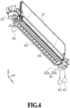
- Fig. 4 is a perspective view of the printing head 22 and illustrates a nozzle formation surface 223.
- Multiple nozzle plates 224 are provided on the nozzle formation surface 223 facing the sheet, and multiple nozzles to eject ink droplets onto the sheet S are provided to each of the multiple nozzle plates 224.
- the first scanner unit 9 is a unit to read the image printed on the sheet S by the printing unit 8 and to detect misalignment and density of the image.
- a detection result of the first scanner unit 9 is used for correction and is, for example, used for position correction and color tone correction.
- the first dryer unit 10 and the second dryer unit 11 are units to reduce the liquid contained in the ink applied on the sheet S by the printing unit 8 and to enhance the fixability between the sheet S and the ink.
- the second dryer unit 11 is arranged downstream of the first dryer unit 10 in the sheet conveyance direction.
- the first dryer unit 10 and the second dryer unit 11 heat the printed sheet S and dry the applied ink.
- hot air is applied to the passing sheet S from at least an ink application surface side to dry the ink application surface.
- a drying system in addition to the system to apply hot air, a system to irradiate a surface of the sheet S with electromagnetic waves (ultraviolet rays, infrared rays, and the like) or a conduction heat transfer system by a contact of a heating device may be combined.
- electromagnetic waves ultraviolet rays, infrared rays, and the like
- a conduction heat transfer system by a contact of a heating device may be combined.
- a winding guide roller 31 is a roller that is arranged downstream of the printing unit 8 in the conveyance direction and winds a surface of the sheet S opposite of the ink application surface at a constant winding angle in order to block an effect of the hot air generated in the first dryer unit 10 on the printing unit 8.
- two winding guide rollers 31 are arranged between the first scanner unit 9 and the first dryer unit 10, and the sheet S is turned back so as to be substantially parallel between an upper portion and a lower portion of the apparatus.
- the first dryer unit 10 is arranged below the printing unit 8, and the second dryer unit 11 is arranged below the conveyance detection unit 6 and the mark sensor unit 7.
- the cooler unit 12 cools down the sheet S on which the ink is fixed by the first dryer unit 10 and the second dryer unit 11 to solidify the softened ink and also to suppress a temperature change of the sheet S over steps of the units arranged downstream of the printing apparatus 1 in the conveyance direction.
- the ink application surface of the sheet S is cooled down by applying wind at a lower temperature than the sheet S from at least the ink application surface side to the sheet S passing through the inside of the cooler unit 12.
- a cooling system is not limited to the system to apply wind.
- a conduction heat transfer system by a contact of a heat dissipation member may be applied, or those systems may be combined.
- the second scanner unit 13 is a unit to read a test image printed on the sheet S by the printing unit 8 before the real printing and to detect misalignment and density of the image. A detection result of the second scanner unit 13 is used for correction in the real printing after printing the test image.
- the second main conveyance unit 14 is a unit that functions by operating with the first main conveyance unit 4 and is a unit to convey the sheet S while applying the tension to the sheet S and to adjust the tension of the sheet S.
- the second main conveyance unit 14 is rotated by being driven by a not-illustrated motor.
- the tension of the sheet S is adjusted by a drivingly coupled clutch (not illustrated) that can control a torque based on a tension value detected by a not-illustrated tension control unit. Note that, as an additional configuration to adjust the tension of the sheet S, a configuration to control a speed of the second main conveyance unit 14 based on a detection result of the conveyance detection unit 6 may be added.
- either of a torque control method to control the value of the torque transmitted from the clutch and a speed control method to control the roller speed of the second main conveyance unit 14 may be considered.
- these two methods may be switched and used depending on purpose, or the two methods may be used concurrently.
- the second dancer unit 15 is a unit to apply constant tension between the second main conveyance unit 14 and the wind-up roll unit 16.
- a not-illustrated tension application unit applies the constant tension to the sheet.
- the wind-up roll unit 16 is a unit to wind up the sheet S subjected to the printing processing around a winding core.
- the number of the collectable roll is one in Fig. 1
- the number of the collectable roll is not limited to one, and a configuration in which two or three or more winding cores are included to collect the sheet S by alternatively switching the winding cores may be applied.
- a configuration to cut the continuous sheet by using a cutter and to stack the cut sheet S may be applied.
- a control unit 21 is a unit taking charge of controlling the units in the printing apparatus 1.
- the control unit 21 includes a CPU, a storage device, a controller including various control units, an external interface, and an operation unit 24 that allows a user to perform input and output.
- An operation of the printing apparatus 1 is controlled based on an instruction inputted via the operation unit 24 or an instruction from a host apparatus 25 such as a host computer connected to the controller via the external interface.
- the maintenance tray 17 is a unit including a mechanism that recovers the ejection performance of the printing head 22.
- a mechanism for example, there may be a cap mechanism that protects an ink ejection surface of the printing head 22, a wipe-out mechanism (a so-called wiping mechanism) that wipes out the ink ejection surface by using a blade and the like, a suction mechanism that sucks the ink in the nozzle from the ink ejection surface with a negative pressure, and the like.
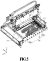
- Fig. 5 is a perspective view of the maintenance tray and the printing head positioned in the maintenance tray.
- the maintenance tray 17 includes a maintenance unit 40 corresponding to each printing head 22 and multiple against-printing-head positioning members 171 in the shape of a sphere to position the printing head 22 to the maintenance unit 40.
- the multiple against-printing-head positioning members 171 corresponding to one printing head 22 are arranged in line in an apparatus depth direction (the y direction) inside the maintenance tray 17 and are held by a beam member 180 extending along the sheet conveyance direction (an x direction).
- three balls of the against-printing-head positioning members 171 are required to position each printing head 22 to the maintenance tray 17, and one is arranged on a front side beam 180a in the maintenance tray 17 while the other two are arranged on a rear side beam 180b.
- a configuration of ball arrangement used for positioning is not limited thereto, and a configuration including two balls on the front side while one ball is on the rear side may be applied, or a configuration in which one ball is arranged on each of the front side and the rear side while the orientation of the printing head 22 is determined by another portion.
- a configuration for positioning is not limited to the configuration using a positioning member in the shape of a sphere. For example, a configuration in which a part of the printing head 22 is struck to the inside of the maintenance tray 17 or a configuration in which positioning is achieved by using a hole and a pin provided to the maintenance tray 17 and the printing head 22 may be employed.
- Figs. 6A to 6C are schematic views illustrating the operation of positioning the printing head 22 to the maintenance tray 17. While the printing operation is performed, the maintenance tray 17 is retracted to a feeding side of the printing apparatus 1 from the printing unit 8.
- the printing head 22 is moved to a position above the sheet conveyance unit housing 81 by the above-mentioned ascending/descending mechanism of the printing head, and the maintenance tray 17 is moved to a position retracted from the printing head (illustrated in Fig. 6A and referred to as a retraction position).
- the maintenance tray 17 is moved to a position below the printing head 22 from the retraction position by a not-illustrated driving mechanism and rail.
- the maintenance tray 17 includes the against-printing-head positioning member 171, and a positioning member 221 of the printing head 22 is provided to a lower portion of the printing head 22. As illustrated in Fig. 6C , the printing head 22 is positioned to the maintenance tray 17 by descending of the printing head 22.
- Figs. 7A and 7B each illustrate a state in which the positioning member 221 of the printing head 22 is distant from the against-printing-head positioning member 171 of the maintenance tray 17.
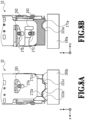
- Figs. 8A and 8B each illustrate a state in which positioning of the positioning member 221 to the against-printing-head positioning member 171 is completed.
- Figs. 7A and 8A are diagrams of a view from an apparatus back surface side
- Figs. 7B and 8B are diagrams of a view from an apparatus front surface side.
- the positioning member 221 there are a recess portion 221a in a conical shape, a groove portion 221b in a V-shape, and a flat surface portion 221c.
- the positioning member 221 of the printing head 22 is put in contact with the against-printing-head positioning member 171 of the maintenance tray 17 by descending of the printing head holding unit 26.
- a first pin 27a of the printing head 22 is moved away from a first hole 261 of the printing head holding unit 26
- a second pin 27b is moved away from the second hole 262
- a third pin 27c is moved away from a third hole 263 by descending of the printing head holding unit 26.
- the positioning member 221 of the printing head 22 is balanced by the against-printing-head positioning member 171, and the printing head 22 is accurately positioned to the maintenance tray 17.
- Fig. 9 illustrates a state in which the printing head 22 is positioned in the maintenance tray 17.
- the nozzle formation surface 223 of the printing head 22 is cleaned by the maintenance unit 40 having various functions for cleaning. Additionally, a region on a lower side (a -z direction side) of the nozzle formation surface 223 is defined as a printing region A (or a projection region A).
- a configuration example of the maintenance unit 40 is described later. Note that, the maintenance unit is also referred to as a "cleaning unit".
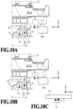
- Figs. 10A and 10B are enlarged views illustrating a positional relationship between the printing head 22 positioned in the maintenance tray 17 and the maintenance unit 40 in a state of being stopped on a front side of the maintenance tray 17.
- the maintenance unit 40 includes a cleaning liquid application unit 50, a liquid removal unit 60, and a negative pressure application unit 70.
- the cleaning liquid application unit 50 is a mechanism to apply the cleaning liquid to the nozzle formation surface 223 of the printing head 22, and Figs. 10A and 10B illustrate a cleaning start position of the cleaning liquid application unit 50 (details are described later).
- the liquid removal unit 60 is a mechanism to remove the ink, paper dust, the cleaning liquid, and the like adhering to the printing head 22.
- the negative pressure application unit 70 is a mechanism to apply a negative pressure to the nozzle plate 224 of the printing head 22 to remove the ink stuck in the nozzle unit or bubbles in the ink channel.
- the cleaning liquid application unit 50, the liquid removal unit 60, and the negative pressure application unit 70 each can scan in the y direction while being put in contact with the nozzle formation surface 223 of the printing head 22.
- the cleaning liquid is applied to the nozzle formation surface 223 by the cleaning liquid application unit 50. Then, the sticking force of the ink stuck on the nozzle formation surface 223 is reduced by the effect of the applied cleaning liquid. Thereafter, with wiping by the liquid removal unit 60, the stuck ink and the cleaning liquid are removed from the nozzle formation surface 223. Thereafter, the negative pressure application unit 70 acts on the nozzle plate 224 and performs negative pressure suction, and the ink stuck in the nozzle unit and fine bubbles in the ink channel are thus removed.
- the above-mentioned three cleaning mechanisms are described as the cleaning mechanism forming the maintenance unit; however, a type of the cleaning mechanism is not limited to these three.
- a configuration to arrange another cleaning mechanism may be applied, such as a configuration in which the nozzle formation surface 223 is cleaned by putting a web for wiping out in contact therewith and a configuration in which a porous body is put in contact with the nozzle formation surface.
- Fig. 10A illustrates an example of the cleaning start position of the cleaning liquid application unit 50.
- the cleaning liquid application unit 50 includes a cleaning liquid application member 51 including a portion that has flexibility and is put in contact with the nozzle formation surface 223 and a bias member 55.
- the cleaning start position of the cleaning liquid application unit 50 is within the printing region A below the nozzle formation surface 223.
- the printing head 22 is moved in a -z direction and put in contact with the cleaning liquid application unit 50 standing by in the cleaning start position.
- a pressing pressure in the -z direction is applied to the cleaning liquid application member 51 having flexibility at a tip of the cleaning liquid application unit 50, and repulsion in a spring bias direction (a +z direction) acts by the bias member 55.
- a +z direction a spring bias direction
- the cleaning liquid application unit 50 includes rubber on a rear side in a scanning direction that is notched by 1 mm in the Z direction so as to stably apply the liquid to the printing head.
- Fig. 10C illustrates a configuration in which the maintenance unit 40 including the cleaning liquid application unit 50 scans from the front side to the rear side in the +y direction while applying the cleaning liquid by the cleaning liquid application unit 50; however, it is not limited to this configuration.
- a configuration in which the maintenance unit 40 scans in the -y direction while applying the cleaning liquid by the cleaning liquid application unit 50 may be applied. Note that, in this configuration, the position of the notch is on a +y direction side of a portion without notch.
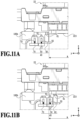
- Fig. 11A illustrates an example of a cleaning start position of the liquid removal unit 60.
- the liquid removal unit 60 includes a blade 61 that has flexibility.
- the number of the blade 61 may be one or more.
- the cleaning start position of the liquid removal unit 60 is a position outside the printing region A below the nozzle formation surface 223 in which the blade 61 is put in contact with no part.
- a deflection direction of the blade 61 put in contact with the nozzle formation surface 223 is uniform (the opposite direction of the advancing direction of the maintenance unit 40). Accordingly, good removal performance is assured.
- Fig. 12A illustrates an example of a cleaning start position of the negative pressure application unit 70.
- the negative pressure application unit 70 includes a negative pressure application member 71 including a portion that has flexibility and is put in contact with the nozzle formation surface 223 and a bias member 75.
- the cleaning start position of the negative pressure application unit 70 is within the printing region A below the nozzle formation surface 223.
- the printing head 22 is moved in the -z direction and put in contact with the negative pressure application unit 70 standing by in the cleaning start position.
- a pressing pressure in the - z direction is applied to the negative pressure application member 71 having flexibility at a tip of the negative pressure application unit 70, and repulsion in a spring bias direction (the +z direction) acts by the bias member 75.
- the maintenance unit 40 advances in the +y direction.
- the negative pressure application unit 70 scans while sucking with the negative pressure, the scanning is performed while being strongly and closely attached to the nozzle plate. Therefore, if the negative pressure application unit 70 advances in a direction to be mounted on a sharp angle portion 233 of the nozzle plate 224 illustrated in Fig. 12C , this causes easy abrasion of the rubber forming the negative pressure application unit 70. In a case where the rubber of the negative pressure application unit 70 is abraded, the rubber needs to be replaced.
- the maintenance unit 40 scans from the front side to the rear side in the +y direction such that the negative pressure application unit 70 advances in a direction not to be mounted on the sharp angle portion 233 of the nozzle plate 224.
- the negative pressure application unit 70 is not put in contact with a sharp angle portion 232 of the nozzle plate 224.
- a sealing material 231 protecting a wire connected with the nozzle plate has a shape bulging from the nozzle plate 224 by about 0.3 mm. That is, in a case where the negative pressure application unit 70 is mounted on the sealing material 231 like straddling, leaking of the negative pressure is increased, and a necessary negative pressure cannot act on the nozzle plate. For this reason, it is designed that the negative pressure application unit 70 is partially mounted on the sealing material 231.
- Fig. 13 illustrates a state in which the printing head 22 is positioned to the against-printing-head positioning member 171 held by the beam member 180 and a state in which the cleaning liquid application unit 50, the liquid removal unit 60, and the negative pressure application unit 70 are retracted in the -z direction from a height of the nozzle formation surface 223.
- the cleaning liquid application unit 50, the liquid removal unit 60, and the negative pressure application unit 70 can act on the nozzle formation surface 223.
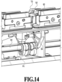
- Fig. 14 illustrates a cam mechanism using a cam as an example of the ascending/descending configuration to ascend/descend the above-described three cleaning mechanisms.
- Figs. 15 to 17 each illustrate a state in which any one of these three cleaning mechanisms is moved to a height (this height is defined as a "head contact height") at which the cleaning mechanism is put in contact with the nozzle formation surface 223 of the printing head 22.
- the maintenance unit 40 illustrated in Figs. 15 to 17 is positioned in a standby position in the y direction, and the negative pressure application unit 70 in the standby position is in a position in which the negative pressure application unit 70 is overlapped with the nozzle formation surface 223 in the y direction.
- Fig. 14 illustrates a cam mechanism using a cam as an example of the ascending/descending configuration to ascend/descend the above-described three cleaning mechanisms.
- Figs. 15 to 17 each illustrate a state in which any one of these three cleaning mechanisms is moved to a height (this height is defined as a
- Fig. 15 illustrates a state in which the cleaning liquid application unit 50 is moved to the head contact height in a case where a y direction position of the maintenance unit 40 is a position (the standby position) (this y direction position is defined as a "first position") in which the height of each cleaning mechanism in the maintenance unit 40 can be changed.
- the cleaning liquid application unit 50 can perform the ascending/descending operation by following a first cam 91 accompanying to a shaft 90 provided below the maintenance unit 40.
- Fig. 16 illustrates a state in which the liquid removal unit 60 is moved to the head contact height in a case where the maintenance unit 40 is in the first position.
- the liquid removal unit 60 can perform the ascending/descending operation by operations of the first cam 91 accompanying to the shaft 90 provided below the maintenance unit 40 and a second cam 92 arranged below the liquid removal unit 60 and following the first cam 91 in conjunction with each other.
- Fig. 17 illustrates a state in which the negative pressure application unit 70 is moved to the head contact height in a case where the maintenance unit 40 is in the first position.
- the negative pressure application unit 70 can perform the ascending/descending operation by operations of the first cam 91 accompanying to the shaft 90 provided below the maintenance unit 40 and a third cam 93 arranged below the negative pressure application unit 70 and following the first cam 91 in conjunction with each other.
- the position in which the height of each cleaning mechanism in the maintenance unit 40 can be changed is the first position on the apparatus front side is described so far with reference to Figs. 15 to 17 .
- the "second position" is a y direction position in which the height of each cleaning mechanism in the maintenance unit 40 can be changed and is a position different from the first position.
- Each of the first position and the second position is outside the printing region A of the printing head 22 in the depth direction.
- Fig. 18 illustrates a state in which the maintenance unit 40 in the maintenance tray 17 is stopped in the second position on the apparatus rear side.
- the second position is in the maintenance tray 17 and on the rear side of the printing region A of the printing head 22.
- a gear train that transmits driving force to a second driving motor 98 and the maintenance unit 40 is also provided on the rear side of the apparatus.
- An advantage in a case where the height of each cleaning mechanism in the maintenance unit 40 can be changed in two places on the front side and the rear side of the printing region A as described above is as follows. That is, with such a configuration, it is possible to clean the nozzle formation surface 223 by using different cleaning mechanisms between a case where the maintenance unit 40 is moved from the apparatus front side to the rear side (in the +y direction) and a case where the maintenance unit 40 is moved from the apparatus rear side to the front side (in the -y direction). Accordingly, it is possible to reduce the cleaning time in a case where the nozzle formation surface 223 is cleaned by using the multiple cleaning mechanisms.
- a blade cleaner 65 (see Fig. 16 ) is required as a configuration to remove the liquid, paper dust, and the like adhering to the blade 61 to recover the removal performance of the blade 61. It is possible to remove the liquid, paper dust, and the like adhering to the blade 61 from the blade 61 with the blade 61 included in the liquid removal unit 60 passing through the blade cleaner 65 in the +y direction or the -y direction.
- the blade cleaner 65 is provided as a part of the cleaning mechanism, and the user additionally needs to perform cleaning of the blade cleaner 65, it is desirable that the blade cleaner 65 is arranged in a position in the maintenance tray 17 that is easily accessed. Accordingly, in the present example, the blade cleaner 65 is arranged on the apparatus front side.
- the arrangement order of the cleaning mechanisms in the maintenance unit 40 is determined taking into consideration not only the above-mentioned cleaning start position of each of the cleaning liquid application unit 50, the liquid removal unit 60, and the negative pressure application unit 70 but also the accessibility to the blade cleaner 65.
- arrangement of the liquid removal unit 60 is described.
- arrangement of the liquid removal unit 60 is determined based on a positional relationship with the blade cleaner 65 taking into consideration the splash of the liquid droplets in a case where the liquid removal unit 60 is put in contact with the blade cleaner 65.
- the blade cleaner 65 is arranged on the apparatus front side, and it should be noted that the good accessibility of the user to the blade cleaner 65 can be secured with this arrangement.
- the blade cleaner 65 In a case where the blade cleaner 65 is arranged on the front side, it is desirable to apply a configuration in which the liquid removal unit 60 is arranged in the maintenance tray 17 and on the foremost side out of the three cleaning mechanisms, and the blade 61 and the blade cleaner 65 are put in contact with each other in scanning from the rear side toward the front side (in the -y direction).
- a splash direction of the liquid droplets that occurs in a case where the liquid removal unit 60 scanning in the -y direction passes through the blade cleaner 65 is the -y direction. Therefore, with the liquid removal unit 60 arranged on the foremost side, it is possible to suppress the splash of the liquid droplets onto the other cleaning mechanism such as the cleaning liquid application unit 50 and the negative pressure application unit 70 arranged on the rear side (+y direction) of the liquid removal unit 60.
- the liquid removal unit 60 is arranged on the outermost side so as to prevent the cleaning liquid application unit 50 and the negative pressure application unit 70 from passing through the y direction position of the blade cleaner 65.
- Fig. 19A illustrates a state in which the maintenance unit 40 is in the first position that is the foremost position in the maintenance tray 17.
- Fig. 19B illustrates a state in which the maintenance unit 40 is in the second position that is the rearmost position in the maintenance tray 17.
- Fig. 20 is an enlarged view of a state in which the maintenance unit 40 is in the second position that is viewed obliquely.
- the cleaning liquid application unit 50 needs to have an X direction width similar to that of the nozzle formation surface 223 to apply the cleaning liquid to the entire nozzle formation surface 223.
- the negative pressure application unit 70 is the cleaning mechanism for the nozzle plate 224, an X direction width does not have to be as long as that of the cleaning liquid application unit 50.
- the negative pressure application unit 70 is arranged on the rearmost side out of the three cleaning mechanisms. With such arrangement, as illustrated in Figs.
- the arrangement order of the cleaning mechanisms is not limited to this order.
- Fig. 21 illustrates a driving force transmission route from the driving motor 96 to the shaft 90 that allows each cleaning mechanism in the maintenance unit 40 to ascend/descend.
- the gear train has a configuration including a pendulum gear 95 as a part thereof, and it is possible to rotate the shaft 90 by rotating the driving motor 96 and to move an arbitrary cleaning mechanism in the maintenance unit 40 to the contact position.
- the pendulum gear 95 is moved away from a shaft gear 97.
- the maintenance unit 40 needs to scan in the +y direction or the -y direction.
- a configuration in which the driving motor 96 for ascending/descending of the cleaning mechanism is moved while being coupled to the maintenance unit 40 during the y direction scanning of the maintenance unit 40 may also be considered.
- the drivingly coupling unit is also moved in the +y direction or the -y direction in addition to the driving motor 96. Therefore, the size of a unit group moved along the y direction (in this case, including the maintenance unit 40, the driving motor 96, and the drivingly coupling unit) during scanning of the maintenance unit 40 is increased.
- the pendulum gear 95 is employed as a coupling/releasing unit that switches between a state of transmitting the driving force to the maintenance unit 40 (a coupling state) and a state of not transmitting the driving force (a coupling release state) in the present embodiment, the coupling/releasing unit is not limited to the pendulum gear 95.
- Fig. 23 is a schematic view illustrating a state in which the liquid removal unit 60 and the cleaning liquid application unit 50 are at the head contact height. In this state, the printing head 22 descends and is positioned to the against-printing-head positioning member 171.
- a cam having a different shape from that in the first embodiment is employed for the first cam 91 arranged below the maintenance unit 40.
- a cam shape that can move both the liquid removal unit 60 and cleaning liquid application unit 50 to the head contact height is employed. With such a cam employed, it is possible to move the liquid removal unit 60 and the cleaning liquid application unit 50 to the head contact height concurrently.
- Fig. 24A is a schematic view illustrating a state in which the printing head 22 is moved in the -z direction and positioned to the maintenance tray 17 with respect to the liquid removal unit 60 and the cleaning liquid application unit 50 standing by in the cleaning start position. Additionally, Fig. 24B illustrates a state immediately after the maintenance unit 40 starts moving in a direction of an arrow G.
- the cleaning start position of the cleaning liquid application unit 50 is in the printing region A below the nozzle formation surface 223.
- the printing head 22 is moved in the -z direction and put in contact with the cleaning liquid application unit 50 standing by in the cleaning start position.
- the pressing pressure in the -z direction is applied to the cleaning liquid application member 51 at the tip of the cleaning liquid application unit 50 that has flexibility, and repulsion in the spring bias direction (+z direction) acts by the bias member 55.
- the cleaning start position of the liquid removal unit 60 is a position outside the printing region A below the nozzle formation surface 223 and in which the blade 61 is put in contact with no part.
- the cleaning liquid application unit 50 is arranged downstream while the liquid removal unit 60 is arranged upstream, and the cleaning liquid application unit 50 and the liquid removal unit 60 are allowed to act on the nozzle formation surface 223 concurrently.
- a configuration in which the cleaning liquid application unit 50 and the liquid removal unit 60 are allowed to act on the printing head 22 concurrently may also be considered. This configuration is also effective to reduce the cleaning time of the printing head 22.
- the negative pressure application unit 70 is allowed to act on the nozzle formation surface 223, since the negative pressure application member 71 having flexibility slides with respect to the nozzle formation surface 223, it is desirable that the cleaning liquid application unit 50 is arranged downstream of the negative pressure application unit 70 in the direction in which the maintenance unit 40 scans.
- a configuration in which the liquid removal unit 60 and the negative pressure application unit 70 are allowed to act concurrently may also be considered.
- This configuration is also effective to reduce the cleaning time of the printing head 22.
- the liquid removal unit 60 is arranged downstream while the negative pressure application unit 70 is arranged upstream.
- Fig. 25 is a flowchart of cleaning (normal cleaning) that is executed on a regular basis during the printing operation as described above. If the liquid application operation is performed first by the cleaning liquid application unit 50, the paper dust adheres to the cleaning liquid application unit 50. Thus, the paper dust is accumulated on the cleaning liquid application unit 50 and eventually leads reduction of the cleaning liquid application performance.
- a step S2501 the paper dust is removed by performing the cleaning operation by the liquid removal unit 60.
- the liquid application operation by the cleaning liquid application unit 50 is performed.
- the cleaning operation by the liquid removal unit 60 is performed, and thus the stuck ink and the cleaning liquid are removed from the nozzle formation surface 223.
- cleaning by the negative pressure application unit 70 is performed to remove the stuck ink near the nozzle.
- Fig. 25 shows the normal cleaning assuming the printing medium that is likely to generate paper dust
- normal cleaning of a different flow may be executed after printing on the printing medium that is less likely to generate paper dust.
- coated paper includes a coated surface layer, loading material and the like of the sheet rarely falls off during conveyance, and the amount of the paper dust generated during printing is considerably small.
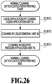
- non-coated paper since non-coated paper is not coated, the amount of the paper dust generated during printing is great. For this reason, the amount of the paper dust adhering to the printing head after the printing on the coated paper is less than that after the printing on the non-coated paper. Therefore, in a case where the coated paper is selected in setting of the printing medium for printing, or after the printing on the coated paper is performed, normal cleaning (after coated paper printing) illustrated in Fig. 26 is performed.
- a step S2601 the cleaning operation by the liquid removal unit 60 is not performed, and the liquid application operation by the cleaning liquid application unit 50 is performed from the beginning. Subsequently, in a step S2602, the cleaning operation by the liquid removal unit 60 is performed. Subsequently, in a step S2603, cleaning by the negative pressure application unit 70 is performed. Note that, the cleaning shown in Fig.
- Fig. 26 is performed in a timing in which the printing time, the passing paper number, or the ink ejection number during printing (the dot number) exceeds the predetermined threshold as with Fig. 25 ; however, it is performed only in a case where the printing media printed after the last cleaning are only the coated paper. In a case where the coated paper and the non-coated paper are mixed in the printing media printed after the last cleaning, the normal cleaning shown in Fig. 25 may be executed.
- Fig. 27 is a flowchart of cleaning (in a case of ink filling) executed in a case where the printing head is filled with the ink after the printing apparatus is disposed, unlike the normal cleaning executed on a regular basis.
- a step S2701 the printing head is filled with the ink by a pressurization operation from a supply pump connected to the printing head and a suction operation by a negative pressure pump via a cap sealing the printing head.
- a large amount of the ink is discharged from the nozzle, and the amount of the ink adhered onto the nozzle formation surface 223 is increased. Therefore, in a step S2702, the liquid removal operation by the liquid removal unit 60 is performed.
- the liquid application operation by the cleaning liquid application unit 50 is performed.
- the cleaning operation by the liquid removal unit 60 is performed.
- cleaning by the negative pressure application unit 70 cleaning by the negative pressure application unit 70 is performed.
- a mode in which the liquid application operation, the liquid removal operation, and the negative pressure application operation are each executed only once is described in Fig. 25 to 27
- the number of the corresponding operations may be multiple times.
- a mode in which the liquid removal operation (S2702) is performed multiple times in a case where the ink adhering amount to the nozzle formation surface after the cap suction is great may be applied.
- Embodiment(s) of the present disclosure can also be realized by a computer of a system or apparatus that reads out and executes computer executable instructions (e.g., one or more programs) recorded on a storage medium (which may also be referred to more fully as a 'non-transitory computer-readable storage medium') to perform the functions of one or more of the above-described embodiment(s) and/or that includes one or more circuits (e.g., application specific integrated circuit (ASIC)) for performing the functions of one or more of the above-described embodiment(s), and by a method performed by the computer of the system or apparatus by, for example, reading out and executing the computer executable instructions from the storage medium to perform the functions of one or more of the above-described embodiment(s) and/or controlling the one or more circuits to perform the functions of one or more of the above-described embodiment(s).
- computer executable instructions e.g., one or more programs
- a storage medium which may also be referred to more fully as
- the computer may comprise one or more processors (e.g., central processing unit (CPU), micro processing unit (MPU)) and may include a network of separate computers or separate processors to read out and execute the computer executable instructions.
- the computer executable instructions may be provided to the computer, for example, from a network or the storage medium.
- the storage medium may include, for example, one or more of a hard disk, a random-access memory (RAM), a read only memory (ROM), a storage of distributed computing systems, an optical disk (such as a compact disc (CD), digital versatile disc (DVD), or Blu-ray Disc (BD) TM ), a flash memory device, a memory card, and the like.
Landscapes
- Ink Jet (AREA)
Abstract
A printing apparatus (1) includes: a cleaning unit (40) including cleaning mechanisms configured to clean a printing head (22) ejecting a liquid, each of the cleaning mechanisms scanning in a predetermined direction while contacting the printing head; a movement mechanism (90) configured to move each of the cleaning mechanisms between a first height in contact with the printing head and a second height not in contact with the printing head; a driving source (96) of the movement mechanism; and a coupling/releasing unit (95) configured to perform coupling/releasing between the driving source and the movement mechanism, in which one or more of the cleaning mechanisms are moved to the first height by the movement mechanism coupled with the driving source, and after the one or more cleaning mechanisms are moved to the first height, the coupling/releasing unit releases coupling between the driving source and the movement mechanism.
Description
- The present disclosure relates to a technique of cleaning a printing head of a printing apparatus.
- Conventionally, there had been known an inkjet printing apparatus as a printing apparatus that prints a character, an image, and the like by ejecting an ink onto a printing medium such as a continuous sheet winding into a roll.
- There has been known a problem in the ink jet printing apparatus that the ink ejected from a nozzle in a process of printing a character, an image, and the like floats as mist without landing on the sheet and adheres to the nozzle, which causes a subsequentlyejected ink droplet to be deviated and causes reduction of the image quality.
- As a solution to this problem, there has been known a configuration in which an ejection nozzle formation surface is wiped out by a blade having elasticity to recover the ejection nozzle surface to a state before ejection and maintain the ejection performance. However, in a case where adherence of the ink adhering to the nozzle formation surface of an ejection head is high, enough removal force cannot be obtained by wiping out by the blade, and it is necessary to mount a cleaning mechanism with higher removal force than the blade.
-
Japanese Patent Laid-Open No. 2019-162862 - However, in
Japanese Patent Laid-Open No. 2019-162862 - Therefore, in light of the above-described problem, an object of the present disclosure is to downsize a printing apparatus.
- The present invention in its first aspect provides a printing apparatus as specified in
claims 1 to 18. - The present invention in its second aspect provides a control method as specified in claims 19
- The present invention in its third aspect provides program as specified in claim 20.
- Further features of the present invention will become apparent from the following description of exemplary embodiments with reference to the attached drawings.
-
-
Fig. 1 is a cross-sectional view illustrating an internal configuration of a printing apparatus; -
Fig. 2 is a perspective view of a sheet conveyance unit housing of a printing unit; -
Fig. 3 is a perspective view of a printing head ascending/descending mechanism; -
Fig. 4 is a perspective view of a printing head; -
Fig. 5 is a perspective view of a maintenance tray and the printing head positioned in the maintenance tray; -
Figs. 6A to 6C are schematic views illustrating a positioning operation of the printing head to the maintenance tray; -
Figs. 7A and 7B are schematic views illustrating a state in which the maintenance tray and the printing head are distant from each other; -
Figs. 8A and 8B are diagrams illustrating a state in which the positioning operation of the printing head to the maintenance tray is completed; -
Fig. 9 is a diagram illustrating the printing head positioned in the maintenance tray; -
Figs. 10A to 10C are schematic views illustrating a cleaning start position of a cleaning liquid application unit; -
Figs. 11A and 11B are schematic views illustrating a cleaning start position of a liquid removal unit; -
Figs. 12A to 12C are schematic views illustrating a cleaning start position of a negative pressure application unit; -
Fig. 13 is a schematic view illustrating a state in which a maintenance unit in a first position (a position in which a height can be changed) of a y direction position is retracted from the printing head; -
Fig. 14 is a diagram illustrating a cam mechanism of the maintenance unit; -
Fig. 15 is a schematic view illustrating a state in which the cleaning liquid application unit in the first position is in a position (a head contact height) in which the cleaning liquid application unit is put in contact with a nozzle formation surface of the printing head; -
Fig. 16 is a schematic view illustrating a state in which the liquid removal unit in the first position is at the head contact height; -
Fig. 17 is a schematic view illustrating a state in which the negative pressure application unit in the first position is at the head contact height; -
Fig. 18 is a schematic view illustrating the maintenance unit in a second position of the y direction position; -
Figs. 19A and 19B are schematic views illustrating a state in which the maintenance unit in the maintenance tray is in the endmost portion of a movable range in a y direction; -
Fig. 20 is a perspective view of the maintenance unit in a state of being the farthest in the maintenance tray; -
Fig. 21 is a schematic view illustrating a state in which the maintenance unit and a driving source are connected to each other; -
Fig. 22 is a schematic view illustrating a state in which the maintenance unit is distant from the driving source; -
Fig. 23 is a schematic view illustrating a state in which the liquid removal unit and the cleaning liquid application unit are at the head contact height; -
Figs. 24A and 24B are schematic views illustrating cleaning start states of the liquid removal unit and the cleaning liquid application unit; -
Fig. 25 is a flowchart of normal cleaning; -
Fig. 26 is a flowchart of normal cleaning (after coated paper printing); and -
Fig. 27 is a flowchart of cleaning in a case of ink filling. - Embodiments according to the present disclosure are described below with reference to the drawings. Note that, in some cases, elements having the same functions or elements of the same intent in the drawings are provided with the same reference numerals, and descriptions thereof are omitted.
-
Fig. 1 is a schematic cross-sectional view illustrating an internal configuration of aprinting apparatus 1. An up and down direction inFig. 1 is defined as a "height direction", a right and left direction inFig. 1 is defined as a "longitudinal direction", and a direction orthogonal to the height direction and the longitudinal direction (a direction from near to far from a paper surface inFig. 1 ) is defined as a "sheet width direction". Additionally, hereinafter, theprinting apparatus 1 is described as a printer that prints an image on a continuous sheet winding in a roll by using an ink and that is a high-speed line printer capable of high-speed printing. - As illustrated in
Fig. 1 , theprinting apparatus 1 includes units therein, which are a wind-down roll unit 2, a first dancer unit 3, a first main conveyance unit 4, a meandering correction unit 5, a conveyance detection unit 6, a mark sensor unit 7, and aprinting unit 8. Additionally, theprinting apparatus 1 includes units as subsequent stage units of theprinting unit 8, which are a first scanner unit 9, afirst dryer unit 10, asecond dryer unit 11, acooler unit 12, asecond scanner unit 13, a secondmain conveyance unit 14, asecond dancer unit 15, a wind-up roll unit 16, and amaintenance tray 17. A sheet S is conveyed along a sheet conveyance route indicated by a solid line inFig. 1 , and the above-mentioned units perform processing on the sheet S. - The wind-down roll unit 2 is a unit to hold and supply a continuous sheet winding in a roll. The wind-down roll unit 2 has a configuration to store a wind-down roll and draw out and supply the sheet S. Note that, although the number of the roll that can be stored is one in
Fig. 1 , the number of the roll that can be stored may not be limited to one, and a configuration in which two or three or more rolls are stored, and the sheet S is alternatively drawn out and supplied from the multiple rolls may be applied. - The first dancer unit 3 is a unit to apply constant sheet tension between the wind-down roll unit 2 and the first main conveyance unit 4. In the first dancer unit 3, sheet tension is applied by a not-illustrated tension application unit.
- The first main conveyance unit 4 is a unit to send the sheet S to a subsequent unit and to apply predetermined tension to the sheet in cooperation with the second
main conveyance unit 14. The first main conveyance unit 4 is rotated by driving a not-illustrated motor and conveys the sheet S while applying the tension to the sheet S. - The meandering correction unit 5 is a unit to correct meandering in the sheet width direction while conveying the sheet S to which the tension is applied. The meandering correction unit 5 includes a
meandering correction roller 5a and a not-illustrated meandering detection sensor that detects meandering of the sheet S. Themeandering correction roller 5a can change tilt of the sheet S by a not-illustrated motor and corrects meandering of the sheet S based on a measurement result of the meandering detection sensor. In this process, it is possible to enhance a function of the meandering correction by winding the sheet S around the meanderingcorrection roller 5a. The meandering correction unit 5 can correct the meandering conveyance direction of the sheet S to a regular conveyance direction. - The conveyance detection unit 6 is a unit to detect the tension while conveying the sheet to which the tension is applied between the first main conveyance unit 4 and the second
main conveyance unit 14. Additionally, the conveyance detection unit 6 is also a unit to detect a speed of the sheet S to control a printing timing of theprinting unit 8. - The mark sensor unit 7 is a unit to detect a mark printed in advance on the sheet S to control the printing timing of the
printing unit 8. - The
printing unit 8 is a unit to perform printing on the conveyed sheet S, and an image is printed by performing printing processing (specifically, ink ejection processing and the like) by aprinting head 22 on the sheet S from above. The conveyance route in theprinting unit 8 is formed bymultiple guide rollers 23 arranged to form a circular arc shape projecting upward, and a clearance between theguide rollers 23 and theprinting head 22 is secured by applying constant tension to the sheet S. In theprinting head 22, multiple printing heads are arrayed along the conveyance direction. Theprinting apparatus 1 of the present example includes eight line type printing heads in total corresponding to four colors, which are Bk (black), Y (yellow), M (magenta), and C (cyan), and additionally a reaction liquid and three special colors. Note that, the number of colors is not limited to four, and the number of the printing heads is not limited to eight. As an ink jet system applied to theprinting head 22, a system using a heating element, a system using a piezoelectric element, a system using an electrostatic element, a system using an MEMS element, and the like can be employed. The ink of each color is supplied from a corresponding ink tank (not illustrated) to theprinting head 22 via an ink tube. - As illustrated in
Fig. 2 , multiple against-printing-head positioning members 811 to position the printing head are provided to a sheetconveyance unit housing 81 of theprinting unit 8. To be specific, three against-printing-head positioning members 811 are provided for oneprinting head 22. These three against-printing-head positioning members 811 have a relationship of pinching the sheet S in different positions in a y direction, and one is provided on a front side (a -y side) inFig. 2 while the other two are provided on a rear side (a +y side) inFig. 2 . -
Fig. 3 is a perspective view illustrating an ascending/descending mechanism of theprinting head 22. As illustrated inFig. 3 , theprinting head 22 is rotatably supported by a printinghead holding unit 26 to hold and ascend/descend theprinting head 22 upward and downward in the form such that theprinting head 22 supports a printinghead support shaft 27 from below. The printinghead holding unit 26 performs the ascending/descending operation upward and downward along a printing head ascending/descendingrail 29 included in a printing head ascending/descendingframe 28 by a not-illustrated driving mechanism included inside the printinghead holding unit 26. -
Fig. 4 is a perspective view of theprinting head 22 and illustrates anozzle formation surface 223.Multiple nozzle plates 224 are provided on thenozzle formation surface 223 facing the sheet, and multiple nozzles to eject ink droplets onto the sheet S are provided to each of themultiple nozzle plates 224. - Here, referring back to
Fig. 1 again, and the constituents inFig. 1 are described. The first scanner unit 9 is a unit to read the image printed on the sheet S by theprinting unit 8 and to detect misalignment and density of the image. A detection result of the first scanner unit 9 is used for correction and is, for example, used for position correction and color tone correction. - The
first dryer unit 10 and thesecond dryer unit 11 are units to reduce the liquid contained in the ink applied on the sheet S by theprinting unit 8 and to enhance the fixability between the sheet S and the ink. Thesecond dryer unit 11 is arranged downstream of thefirst dryer unit 10 in the sheet conveyance direction. Thefirst dryer unit 10 and thesecond dryer unit 11 heat the printed sheet S and dry the applied ink. In thefirst dryer unit 10 and thesecond dryer unit 11, hot air is applied to the passing sheet S from at least an ink application surface side to dry the ink application surface. Note that, as a drying system, in addition to the system to apply hot air, a system to irradiate a surface of the sheet S with electromagnetic waves (ultraviolet rays, infrared rays, and the like) or a conduction heat transfer system by a contact of a heating device may be combined. - A winding
guide roller 31 is a roller that is arranged downstream of theprinting unit 8 in the conveyance direction and winds a surface of the sheet S opposite of the ink application surface at a constant winding angle in order to block an effect of the hot air generated in thefirst dryer unit 10 on theprinting unit 8. In the present example, two windingguide rollers 31 are arranged between the first scanner unit 9 and thefirst dryer unit 10, and the sheet S is turned back so as to be substantially parallel between an upper portion and a lower portion of the apparatus. Thefirst dryer unit 10 is arranged below theprinting unit 8, and thesecond dryer unit 11 is arranged below the conveyance detection unit 6 and the mark sensor unit 7. - The
cooler unit 12 cools down the sheet S on which the ink is fixed by thefirst dryer unit 10 and thesecond dryer unit 11 to solidify the softened ink and also to suppress a temperature change of the sheet S over steps of the units arranged downstream of theprinting apparatus 1 in the conveyance direction. The ink application surface of the sheet S is cooled down by applying wind at a lower temperature than the sheet S from at least the ink application surface side to the sheet S passing through the inside of thecooler unit 12. Note that, a cooling system is not limited to the system to apply wind. A conduction heat transfer system by a contact of a heat dissipation member may be applied, or those systems may be combined. - The
second scanner unit 13 is a unit to read a test image printed on the sheet S by theprinting unit 8 before the real printing and to detect misalignment and density of the image. A detection result of thesecond scanner unit 13 is used for correction in the real printing after printing the test image. - The second
main conveyance unit 14 is a unit that functions by operating with the first main conveyance unit 4 and is a unit to convey the sheet S while applying the tension to the sheet S and to adjust the tension of the sheet S. The secondmain conveyance unit 14 is rotated by being driven by a not-illustrated motor. The tension of the sheet S is adjusted by a drivingly coupled clutch (not illustrated) that can control a torque based on a tension value detected by a not-illustrated tension control unit. Note that, as an additional configuration to adjust the tension of the sheet S, a configuration to control a speed of the secondmain conveyance unit 14 based on a detection result of the conveyance detection unit 6 may be added. As a method of implementing this configuration, either of a torque control method to control the value of the torque transmitted from the clutch and a speed control method to control the roller speed of the secondmain conveyance unit 14 may be considered. Alternatively, these two methods may be switched and used depending on purpose, or the two methods may be used concurrently. - The
second dancer unit 15 is a unit to apply constant tension between the secondmain conveyance unit 14 and the wind-up roll unit 16. In thesecond dancer unit 15, a not-illustrated tension application unit applies the constant tension to the sheet. - The wind-
up roll unit 16 is a unit to wind up the sheet S subjected to the printing processing around a winding core. Note that, although the number of the collectable roll is one inFig. 1 , the number of the collectable roll is not limited to one, and a configuration in which two or three or more winding cores are included to collect the sheet S by alternatively switching the winding cores may be applied. Note that, depending on the contents of the processing after printing, instead of a configuration to wind up the sheet S around the winding core, a configuration to cut the continuous sheet by using a cutter and to stack the cut sheet S may be applied. - A
control unit 21 is a unit taking charge of controlling the units in theprinting apparatus 1. Thecontrol unit 21 includes a CPU, a storage device, a controller including various control units, an external interface, and anoperation unit 24 that allows a user to perform input and output. An operation of theprinting apparatus 1 is controlled based on an instruction inputted via theoperation unit 24 or an instruction from ahost apparatus 25 such as a host computer connected to the controller via the external interface. - The
maintenance tray 17 is a unit including a mechanism that recovers the ejection performance of theprinting head 22. As such a mechanism, for example, there may be a cap mechanism that protects an ink ejection surface of theprinting head 22, a wipe-out mechanism (a so-called wiping mechanism) that wipes out the ink ejection surface by using a blade and the like, a suction mechanism that sucks the ink in the nozzle from the ink ejection surface with a negative pressure, and the like. -
Fig. 5 is a perspective view of the maintenance tray and the printing head positioned in the maintenance tray. As illustrated inFig. 5 , themaintenance tray 17 includes amaintenance unit 40 corresponding to eachprinting head 22 and multiple against-printing-head positioning members 171 in the shape of a sphere to position theprinting head 22 to themaintenance unit 40. The multiple against-printing-head positioning members 171 corresponding to oneprinting head 22 are arranged in line in an apparatus depth direction (the y direction) inside themaintenance tray 17 and are held by abeam member 180 extending along the sheet conveyance direction (an x direction). In the present example, three balls of the against-printing-head positioning members 171 are required to position each printinghead 22 to themaintenance tray 17, and one is arranged on afront side beam 180a in themaintenance tray 17 while the other two are arranged on arear side beam 180b. Note that, a configuration of ball arrangement used for positioning is not limited thereto, and a configuration including two balls on the front side while one ball is on the rear side may be applied, or a configuration in which one ball is arranged on each of the front side and the rear side while the orientation of theprinting head 22 is determined by another portion. Additionally, a configuration for positioning is not limited to the configuration using a positioning member in the shape of a sphere. For example, a configuration in which a part of theprinting head 22 is struck to the inside of themaintenance tray 17 or a configuration in which positioning is achieved by using a hole and a pin provided to themaintenance tray 17 and theprinting head 22 may be employed. -
Figs. 6A to 6C are schematic views illustrating the operation of positioning theprinting head 22 to themaintenance tray 17. While the printing operation is performed, themaintenance tray 17 is retracted to a feeding side of theprinting apparatus 1 from theprinting unit 8. - In a case of performing a maintenance operation of the
printing head 22, theprinting head 22 is moved to a position above the sheetconveyance unit housing 81 by the above-mentioned ascending/descending mechanism of the printing head, and themaintenance tray 17 is moved to a position retracted from the printing head (illustrated inFig. 6A and referred to as a retraction position). - Thereafter, as illustrated in
Fig. 6B, themaintenance tray 17 is moved to a position below theprinting head 22 from the retraction position by a not-illustrated driving mechanism and rail. - The
maintenance tray 17 includes the against-printing-head positioning member 171, and apositioning member 221 of theprinting head 22 is provided to a lower portion of theprinting head 22. As illustrated inFig. 6C , theprinting head 22 is positioned to themaintenance tray 17 by descending of theprinting head 22. -
Figs. 7A and 7B each illustrate a state in which thepositioning member 221 of theprinting head 22 is distant from the against-printing-head positioning member 171 of themaintenance tray 17. On the other hand,Figs. 8A and 8B each illustrate a state in which positioning of thepositioning member 221 to the against-printing-head positioning member 171 is completed. Note that,Figs. 7A and8A are diagrams of a view from an apparatus back surface side, andFigs. 7B and8B are diagrams of a view from an apparatus front surface side. Additionally, as illustrated inFigs. 7A and 7B andFigs. 8A and 8B , as thepositioning member 221, there are arecess portion 221a in a conical shape, agroove portion 221b in a V-shape, and aflat surface portion 221c. - As illustrated in
Figs. 7A and 7B andFigs. 8A and 8B , the positioningmember 221 of theprinting head 22 is put in contact with the against-printing-head positioning member 171 of themaintenance tray 17 by descending of the printinghead holding unit 26. In addition, afirst pin 27a of theprinting head 22 is moved away from afirst hole 261 of the printinghead holding unit 26, asecond pin 27b is moved away from thesecond hole 262, and athird pin 27c is moved away from athird hole 263 by descending of the printinghead holding unit 26. In this process, the positioningmember 221 of theprinting head 22 is balanced by the against-printing-head positioning member 171, and theprinting head 22 is accurately positioned to themaintenance tray 17. -
Fig. 9 illustrates a state in which theprinting head 22 is positioned in themaintenance tray 17. Thenozzle formation surface 223 of theprinting head 22 is cleaned by themaintenance unit 40 having various functions for cleaning. Additionally, a region on a lower side (a -z direction side) of thenozzle formation surface 223 is defined as a printing region A (or a projection region A). A configuration example of themaintenance unit 40 is described later. Note that, the maintenance unit is also referred to as a "cleaning unit". -
Figs. 10A and 10B are enlarged views illustrating a positional relationship between theprinting head 22 positioned in themaintenance tray 17 and themaintenance unit 40 in a state of being stopped on a front side of themaintenance tray 17. Themaintenance unit 40 includes a cleaningliquid application unit 50, aliquid removal unit 60, and a negativepressure application unit 70. The cleaningliquid application unit 50 is a mechanism to apply the cleaning liquid to thenozzle formation surface 223 of theprinting head 22, andFigs. 10A and 10B illustrate a cleaning start position of the cleaning liquid application unit 50 (details are described later). Theliquid removal unit 60 is a mechanism to remove the ink, paper dust, the cleaning liquid, and the like adhering to theprinting head 22. The negativepressure application unit 70 is a mechanism to apply a negative pressure to thenozzle plate 224 of theprinting head 22 to remove the ink stuck in the nozzle unit or bubbles in the ink channel. The cleaningliquid application unit 50, theliquid removal unit 60, and the negativepressure application unit 70 each can scan in the y direction while being put in contact with thenozzle formation surface 223 of theprinting head 22. - Here, a series of maintenance operations by the
maintenance unit 40 is described. First, the cleaning liquid is applied to thenozzle formation surface 223 by the cleaningliquid application unit 50. Then, the sticking force of the ink stuck on thenozzle formation surface 223 is reduced by the effect of the applied cleaning liquid. Thereafter, with wiping by theliquid removal unit 60, the stuck ink and the cleaning liquid are removed from thenozzle formation surface 223. Thereafter, the negativepressure application unit 70 acts on thenozzle plate 224 and performs negative pressure suction, and the ink stuck in the nozzle unit and fine bubbles in the ink channel are thus removed. Note that, in this case, the above-mentioned three cleaning mechanisms are described as the cleaning mechanism forming the maintenance unit; however, a type of the cleaning mechanism is not limited to these three. A configuration to arrange another cleaning mechanism may be applied, such as a configuration in which thenozzle formation surface 223 is cleaned by putting a web for wiping out in contact therewith and a configuration in which a porous body is put in contact with the nozzle formation surface. - The cleaning start position corresponding to each cleaning mechanism forming the maintenance unit is described below with reference to
Figs. 10A to 12C . -
Fig. 10A illustrates an example of the cleaning start position of the cleaningliquid application unit 50. The cleaningliquid application unit 50 includes a cleaningliquid application member 51 including a portion that has flexibility and is put in contact with thenozzle formation surface 223 and abias member 55. The cleaning start position of the cleaningliquid application unit 50 is within the printing region A below thenozzle formation surface 223. Theprinting head 22 is moved in a -z direction and put in contact with the cleaningliquid application unit 50 standing by in the cleaning start position. Then, as illustrated inFig. 10B , a pressing pressure in the -z direction is applied to the cleaningliquid application member 51 having flexibility at a tip of the cleaningliquid application unit 50, and repulsion in a spring bias direction (a +z direction) acts by thebias member 55. Thus, it is possible to obtain the proper orientation of the cleaningliquid application unit 50 to start cleaning. After cleaning is started, themaintenance unit 40 advances in the +y direction. - As illustrated in
Fig. 10C , the cleaningliquid application unit 50 includes rubber on a rear side in a scanning direction that is notched by 1 mm in the Z direction so as to stably apply the liquid to the printing head.Fig. 10C illustrates a configuration in which themaintenance unit 40 including the cleaningliquid application unit 50 scans from the front side to the rear side in the +y direction while applying the cleaning liquid by the cleaningliquid application unit 50; however, it is not limited to this configuration. A configuration in which themaintenance unit 40 scans in the -y direction while applying the cleaning liquid by the cleaningliquid application unit 50 may be applied. Note that, in this configuration, the position of the notch is on a +y direction side of a portion without notch. -
Fig. 11A illustrates an example of a cleaning start position of theliquid removal unit 60. Theliquid removal unit 60 includes ablade 61 that has flexibility. The number of theblade 61 may be one or more. As illustrated inFig. 11A , the cleaning start position of theliquid removal unit 60 is a position outside the printing region A below thenozzle formation surface 223 in which theblade 61 is put in contact with no part. Thus, as illustrated inFig. 11B , after cleaning is started, in a case where themaintenance unit 40 advances in the -y direction, and theblade 61 enters the inside of the printing region A, a deflection direction of theblade 61 put in contact with thenozzle formation surface 223 is uniform (the opposite direction of the advancing direction of the maintenance unit 40). Accordingly, good removal performance is assured. -
Fig. 12A illustrates an example of a cleaning start position of the negativepressure application unit 70. The negativepressure application unit 70 includes a negativepressure application member 71 including a portion that has flexibility and is put in contact with thenozzle formation surface 223 and abias member 75. The cleaning start position of the negativepressure application unit 70 is within the printing region A below thenozzle formation surface 223. Theprinting head 22 is moved in the -z direction and put in contact with the negativepressure application unit 70 standing by in the cleaning start position. Then, as illustrated inFig. 12B , a pressing pressure in the - z direction is applied to the negativepressure application member 71 having flexibility at a tip of the negativepressure application unit 70, and repulsion in a spring bias direction (the +z direction) acts by thebias member 75. Thus, it is possible to obtain the proper orientation of the negativepressure application unit 70 to start cleaning. After cleaning is started, themaintenance unit 40 advances in the +y direction. - Since the negative
pressure application unit 70 scans while sucking with the negative pressure, the scanning is performed while being strongly and closely attached to the nozzle plate. Therefore, if the negativepressure application unit 70 advances in a direction to be mounted on asharp angle portion 233 of thenozzle plate 224 illustrated inFig. 12C , this causes easy abrasion of the rubber forming the negativepressure application unit 70. In a case where the rubber of the negativepressure application unit 70 is abraded, the rubber needs to be replaced. Themaintenance unit 40 scans from the front side to the rear side in the +y direction such that the negativepressure application unit 70 advances in a direction not to be mounted on thesharp angle portion 233 of thenozzle plate 224. - Note that, it is designed such that the negative
pressure application unit 70 is not put in contact with asharp angle portion 232 of thenozzle plate 224. This is a result of taking into consideration that a sealingmaterial 231 protecting a wire connected with the nozzle plate has a shape bulging from thenozzle plate 224 by about 0.3 mm. That is, in a case where the negativepressure application unit 70 is mounted on the sealingmaterial 231 like straddling, leaking of the negative pressure is increased, and a necessary negative pressure cannot act on the nozzle plate. For this reason, it is designed that the negativepressure application unit 70 is partially mounted on the sealingmaterial 231. -
Fig. 13 illustrates a state in which theprinting head 22 is positioned to the against-printing-head positioning member 171 held by thebeam member 180 and a state in which the cleaningliquid application unit 50, theliquid removal unit 60, and the negativepressure application unit 70 are retracted in the -z direction from a height of thenozzle formation surface 223. In this state, none of the cleaningliquid application unit 50, theliquid removal unit 60, and the negativepressure application unit 70 can act on thenozzle formation surface 223. In a case of allowing any one of the cleaningliquid application unit 50, theliquid removal unit 60, and the negativepressure application unit 70 to act on thenozzle formation surface 223, it is necessary to move (ascend) the cleaning mechanism (a functional unit) desired to act to a position (a head contact position) in which the cleaning mechanism can be put in contact with thenozzle formation surface 223. -
Fig. 14 illustrates a cam mechanism using a cam as an example of the ascending/descending configuration to ascend/descend the above-described three cleaning mechanisms.Figs. 15 to 17 each illustrate a state in which any one of these three cleaning mechanisms is moved to a height (this height is defined as a "head contact height") at which the cleaning mechanism is put in contact with thenozzle formation surface 223 of theprinting head 22. Note that, themaintenance unit 40 illustrated inFigs. 15 to 17 is positioned in a standby position in the y direction, and the negativepressure application unit 70 in the standby position is in a position in which the negativepressure application unit 70 is overlapped with thenozzle formation surface 223 in the y direction. As illustrated inFig. 15 and so on, in the ascending/descending operation of each cleaning mechanism, it is a state in which theprinting head 22 is retracted to a position away from the against-printing-head positioning member 171 by a predetermined distance in the +z direction. Thus, the negativepressure application unit 70 is not put in contact with thenozzle formation surface 223 of theprinting head 22 during the ascending/descending operation of each cleaning mechanism of themaintenance unit 40, and it is possible to smoothly ascend/descend each cleaning mechanism. -
Fig. 15 illustrates a state in which the cleaningliquid application unit 50 is moved to the head contact height in a case where a y direction position of themaintenance unit 40 is a position (the standby position) (this y direction position is defined as a "first position") in which the height of each cleaning mechanism in themaintenance unit 40 can be changed. The cleaningliquid application unit 50 can perform the ascending/descending operation by following afirst cam 91 accompanying to ashaft 90 provided below themaintenance unit 40. -
Fig. 16 illustrates a state in which theliquid removal unit 60 is moved to the head contact height in a case where themaintenance unit 40 is in the first position. Theliquid removal unit 60 can perform the ascending/descending operation by operations of thefirst cam 91 accompanying to theshaft 90 provided below themaintenance unit 40 and asecond cam 92 arranged below theliquid removal unit 60 and following thefirst cam 91 in conjunction with each other. -
Fig. 17 illustrates a state in which the negativepressure application unit 70 is moved to the head contact height in a case where themaintenance unit 40 is in the first position. The negativepressure application unit 70 can perform the ascending/descending operation by operations of thefirst cam 91 accompanying to theshaft 90 provided below themaintenance unit 40 and athird cam 93 arranged below the negativepressure application unit 70 and following thefirst cam 91 in conjunction with each other. - In the present embodiment, as mentioned above, a configuration to ascend/descend each cleaning mechanism of the
maintenance unit 40 by using thefirst cam 91 accompanying to the oneshaft 90 is employed. With such a configuration, it is possible to implement ascending/descending of multiple cleaning mechanisms by one driving source, and accordingly, it is possible to ascend/descend the multiple cleaning mechanisms in a small space. - Note that, a case where the position in which the height of each cleaning mechanism in the
maintenance unit 40 can be changed is the first position on the apparatus front side is described so far with reference toFigs. 15 to 17 . However, it is possible to apply a configuration in which the height of each cleaning mechanism can be changed also in a second position on the apparatus rear side in addition to the first position. This is described with reference toFig. 18 . Note that, the "second position" is a y direction position in which the height of each cleaning mechanism in themaintenance unit 40 can be changed and is a position different from the first position. Each of the first position and the second position is outside the printing region A of theprinting head 22 in the depth direction. -
Fig. 18 illustrates a state in which themaintenance unit 40 in themaintenance tray 17 is stopped in the second position on the apparatus rear side. The second position is in themaintenance tray 17 and on the rear side of the printing region A of theprinting head 22. As illustrated inFig. 18 , as a configuration to ascend/descend each cleaning mechanism in themaintenance unit 40, a gear train that transmits driving force to asecond driving motor 98 and themaintenance unit 40 is also provided on the rear side of the apparatus. - An advantage in a case where the height of each cleaning mechanism in the
maintenance unit 40 can be changed in two places on the front side and the rear side of the printing region A as described above is as follows. That is, with such a configuration, it is possible to clean thenozzle formation surface 223 by using different cleaning mechanisms between a case where themaintenance unit 40 is moved from the apparatus front side to the rear side (in the +y direction) and a case where themaintenance unit 40 is moved from the apparatus rear side to the front side (in the -y direction). Accordingly, it is possible to reduce the cleaning time in a case where thenozzle formation surface 223 is cleaned by using the multiple cleaning mechanisms. - Although the
nozzle formation surface 223 is cleaned by themaintenance unit 40, in some cases, a blade cleaner 65 (seeFig. 16 ) is required as a configuration to remove the liquid, paper dust, and the like adhering to theblade 61 to recover the removal performance of theblade 61. It is possible to remove the liquid, paper dust, and the like adhering to theblade 61 from theblade 61 with theblade 61 included in theliquid removal unit 60 passing through the blade cleaner 65 in the +y direction or the -y direction. In a case where theblade cleaner 65 is provided as a part of the cleaning mechanism, and the user additionally needs to perform cleaning of theblade cleaner 65, it is desirable that theblade cleaner 65 is arranged in a position in themaintenance tray 17 that is easily accessed. Accordingly, in the present example, theblade cleaner 65 is arranged on the apparatus front side. - It is desirable that the arrangement order of the cleaning mechanisms in the
maintenance unit 40 is determined taking into consideration not only the above-mentioned cleaning start position of each of the cleaningliquid application unit 50, theliquid removal unit 60, and the negativepressure application unit 70 but also the accessibility to theblade cleaner 65. - Additionally, there is a possibility of occurrence of a splash of the ink from the
blade 61 after theblade 61 passes through theblade cleaner 65. Therefore, it should be taken into consideration that there is a concern that, in a case where a cleaning mechanism other than theliquid removal unit 60, such as the cleaningliquid application unit 50 or the negativepressure application unit 70, is arranged in the ink splash direction, the liquid droplets may splash the other cleaning mechanism. - First, arrangement of the
liquid removal unit 60 is described. In the present embodiment, arrangement of theliquid removal unit 60 is determined based on a positional relationship with the blade cleaner 65 taking into consideration the splash of the liquid droplets in a case where theliquid removal unit 60 is put in contact with theblade cleaner 65. In this case, in the printing apparatus having good accessibility from the apparatus front side, it is desirable that theblade cleaner 65 is arranged on the apparatus front side, and it should be noted that the good accessibility of the user to theblade cleaner 65 can be secured with this arrangement. - In a case where the
blade cleaner 65 is arranged on the front side, it is desirable to apply a configuration in which theliquid removal unit 60 is arranged in themaintenance tray 17 and on the foremost side out of the three cleaning mechanisms, and theblade 61 and theblade cleaner 65 are put in contact with each other in scanning from the rear side toward the front side (in the -y direction). A splash direction of the liquid droplets that occurs in a case where theliquid removal unit 60 scanning in the -y direction passes through theblade cleaner 65 is the -y direction. Therefore, with theliquid removal unit 60 arranged on the foremost side, it is possible to suppress the splash of the liquid droplets onto the other cleaning mechanism such as the cleaningliquid application unit 50 and the negativepressure application unit 70 arranged on the rear side (+y direction) of theliquid removal unit 60. Thus, regarding arrangement of theliquid removal unit 60 out of the cleaningliquid application unit 50, theliquid removal unit 60, and the negativepressure application unit 70, it is desirable that theliquid removal unit 60 is arranged on the outermost side so as to prevent the cleaningliquid application unit 50 and the negativepressure application unit 70 from passing through the y direction position of theblade cleaner 65. - Next, the arrangement order of the cleaning
liquid application unit 50 and the negativepressure application unit 70 is described with reference toFigs. 19A and 19B andFig. 20 .Fig. 19A illustrates a state in which themaintenance unit 40 is in the first position that is the foremost position in themaintenance tray 17. Additionally,Fig. 19B illustrates a state in which themaintenance unit 40 is in the second position that is the rearmost position in themaintenance tray 17. In addition,Fig. 20 is an enlarged view of a state in which themaintenance unit 40 is in the second position that is viewed obliquely. - As illustrated in
Fig. 20 , the cleaningliquid application unit 50 needs to have an X direction width similar to that of thenozzle formation surface 223 to apply the cleaning liquid to the entirenozzle formation surface 223. In contrast, since the negativepressure application unit 70 is the cleaning mechanism for thenozzle plate 224, an X direction width does not have to be as long as that of the cleaningliquid application unit 50. As illustrated inFig. 19B , in a case where a movement amount of themaintenance unit 40 needs to be a movement amount that allows for entering below therear side beam 180b, the negativepressure application unit 70 is arranged on the rearmost side out of the three cleaning mechanisms. With such arrangement, as illustrated inFigs. 19B and20 , it is possible to reduce a notch amount of therear side beam 180b to avoid interference more than that in a case where the cleaningliquid application unit 50 is arranged on the rearmost side. Accordingly, it is possible to form themaintenance tray 17 having high strength. - Note that, although a mode in which the
liquid removal unit 60, the cleaningliquid application unit 50, and the negativepressure application unit 70 are arranged in this order from the apparatus front side as an arrangement example of the cleaning mechanisms forming themaintenance unit 40 is described herein, the arrangement order of the cleaning mechanisms is not limited to this order. - It is necessary to supply the driving force from the driving source coupled to the
maintenance unit 40 for the ascending/descending operation of each cleaning mechanism in themaintenance unit 40. In the present embodiment, a configuration using a drivingmotor 96 as the driving source and the gear train is used as a driving force transmission unit is employed. Such a configuration is described with reference toFigs. 21 and22 . -
Fig. 21 illustrates a driving force transmission route from the drivingmotor 96 to theshaft 90 that allows each cleaning mechanism in themaintenance unit 40 to ascend/descend. As illustrated inFig. 21 , the gear train has a configuration including apendulum gear 95 as a part thereof, and it is possible to rotate theshaft 90 by rotating the drivingmotor 96 and to move an arbitrary cleaning mechanism in themaintenance unit 40 to the contact position. Additionally, as illustrated inFig. 22 , in a case where a rotation direction of the drivingmotor 96 is inverted while themaintenance unit 40 is in the first position, thependulum gear 95 is moved away from ashaft gear 97. Likewise, in a case where a rotation direction of thesecond driving motor 98 is inverted while themaintenance unit 40 is in the second position, the pendulum gear is moved away from the shaft gear 97 (seeFig. 18 ). Note that, even in a case where theshaft gear 97 is separated from the driving source for ascending/descending of themaintenance unit 40, a state in which a specific cleaning mechanism ascends in themaintenance unit 40 is maintained. - In a case where the driving
motor 96 is controlled by thecontrol unit 21, and a desired cleaning mechanism is moved to the contact position of thenozzle formation surface 223 to perform the cleaning operation, themaintenance unit 40 needs to scan in the +y direction or the -y direction. A configuration in which the drivingmotor 96 for ascending/descending of the cleaning mechanism is moved while being coupled to themaintenance unit 40 during the y direction scanning of themaintenance unit 40 may also be considered. However, with such a configuration, the drivingly coupling unit is also moved in the +y direction or the -y direction in addition to the drivingmotor 96. Therefore, the size of a unit group moved along the y direction (in this case, including themaintenance unit 40, the drivingmotor 96, and the drivingly coupling unit) during scanning of themaintenance unit 40 is increased. - On the other hand, it is possible to reduce the size of a unit group moved along the y direction by separating the driving
motor 96 and the gear train for driving force transmission from themaintenance unit 40 as mentioned above (in this case, not including the drivingmotor 96 and the drivingly coupling unit). Accordingly, this contributes to downsizing of the printing apparatus. - Note that, although the
pendulum gear 95 is employed as a coupling/releasing unit that switches between a state of transmitting the driving force to the maintenance unit 40 (a coupling state) and a state of not transmitting the driving force (a coupling release state) in the present embodiment, the coupling/releasing unit is not limited to thependulum gear 95. - In the first embodiment, only arbitrary one cleaning mechanism in the
maintenance unit 40 is moved to the head contact height, and only the moved one cleaning mechanism is allowed to act on thenozzle formation surface 223. In contrast, in the present embodiment, arbitrary multiple cleaning mechanisms in themaintenance unit 40 are moved to the head contact height, and the moved multiple cleaning mechanisms are allowed to act on thenozzle formation surface 223 concurrently. -
Fig. 23 is a schematic view illustrating a state in which theliquid removal unit 60 and the cleaningliquid application unit 50 are at the head contact height. In this state, theprinting head 22 descends and is positioned to the against-printing-head positioning member 171. - As illustrated in
Fig. 23 , in the present embodiment, a cam having a different shape from that in the first embodiment is employed for thefirst cam 91 arranged below themaintenance unit 40. Specifically, a cam shape that can move both theliquid removal unit 60 and cleaningliquid application unit 50 to the head contact height is employed. With such a cam employed, it is possible to move theliquid removal unit 60 and the cleaningliquid application unit 50 to the head contact height concurrently. -
Fig. 24A is a schematic view illustrating a state in which theprinting head 22 is moved in the -z direction and positioned to themaintenance tray 17 with respect to theliquid removal unit 60 and the cleaningliquid application unit 50 standing by in the cleaning start position. Additionally,Fig. 24B illustrates a state immediately after themaintenance unit 40 starts moving in a direction of an arrow G. - The cleaning start position of the cleaning
liquid application unit 50 is in the printing region A below thenozzle formation surface 223. Theprinting head 22 is moved in the -z direction and put in contact with the cleaningliquid application unit 50 standing by in the cleaning start position. Then, as illustrated inFig. 24A , the pressing pressure in the -z direction is applied to the cleaningliquid application member 51 at the tip of the cleaningliquid application unit 50 that has flexibility, and repulsion in the spring bias direction (+z direction) acts by thebias member 55. Thus, it is possible to obtain the proper orientation of the cleaningliquid application unit 50 to start cleaning. - The cleaning start position of the
liquid removal unit 60 is a position outside the printing region A below thenozzle formation surface 223 and in which theblade 61 is put in contact with no part. With such a configuration, after cleaning is started, and once theblade 61 enters the inside of the printing region A, a deflection direction of theblade 61 put in contact with thenozzle formation surface 223 is the opposite direction of the advancing direction of themaintenance unit 40, and good removal performance is assured. - After the cleaning liquid is applied to the
nozzle formation surface 223, if the process proceeds to the printing operation without removing the cleaning liquid from thenozzle formation surface 223, there is a possibility that a liquid droplet of the cleaning liquid adhering on thenozzle formation surface 223 adheres to the printing medium. Accordingly, it is necessary to remove the liquid droplet adhering on thenozzle formation surface 223 before the next printing operation, and to this end, the liquid removal operation by theliquid removal unit 60 is required. In the present embodiment, in the G direction in which themaintenance unit 40 scans, the cleaningliquid application unit 50 is arranged downstream while theliquid removal unit 60 is arranged upstream, and the cleaningliquid application unit 50 and theliquid removal unit 60 are allowed to act on thenozzle formation surface 223 concurrently. Thus, it is possible to reduce the time required to clean theprinting head 22 more than a case where the cleaningliquid application unit 50 and theliquid removal unit 60 act individually and sequentially. - In addition to the above-described configuration in which the cleaning
liquid application unit 50 and theliquid removal unit 60 are allowed to act on theprinting head 22 concurrently, a configuration in which the cleaningliquid application unit 50 and the negativepressure application unit 70 are allowed to act concurrently may also be considered. This configuration is also effective to reduce the cleaning time of theprinting head 22. In a case where the negativepressure application unit 70 is allowed to act on thenozzle formation surface 223, since the negativepressure application member 71 having flexibility slides with respect to thenozzle formation surface 223, it is desirable that the cleaningliquid application unit 50 is arranged downstream of the negativepressure application unit 70 in the direction in which themaintenance unit 40 scans. With such arrangement, it is possible to reduce a sliding resistance by arranging the cleaning liquid between thenozzle formation surface 223 and the negativepressure application member 71 and to stabilize the negative pressure application operation. After the cleaningliquid application unit 50 and the negativepressure application unit 70 act concurrently, theliquid removal unit 60 is allowed to act on thenozzle formation surface 223. Thus, the remaining liquid droplet of the cleaning liquid on thenozzle formation surface 223 is removed. - Additionally, a configuration in which the
liquid removal unit 60 and the negativepressure application unit 70 are allowed to act concurrently may also be considered. This configuration is also effective to reduce the cleaning time of theprinting head 22. In this configuration, it is possible to recover the ejection performance of theprinting head 22 by allowing theliquid removal unit 60 and the negativepressure application unit 70 to act on thenozzle formation surface 223 concurrently after the cleaningliquid application unit 50 is allowed to act on thenozzle formation surface 223. Moreover, in the direction in which themaintenance unit 40 is moved during the cleaning operation, theliquid removal unit 60 is arranged downstream while the negativepressure application unit 70 is arranged upstream. Thus, it is possible to remove the liquid droplet of the cleaning liquid adhering on thenozzle formation surface 223 by theliquid removal unit 60 and to suppress adhering of the liquid droplet to the negativepressure application unit 70. - With the above-described configuration, it is possible to maintain the cleaning capability of the
printing head 22 for long time. - The order to operate the three cleaning mechanisms is described below.
- There is a case where paper dust is generated from the printing medium during the printing operation, and the paper dust adheres to the printing head. To deal with this, the printing head is cleaned once the printing time, the passing paper number, or the ink ejection number during printing (the dot number) exceeds a predetermined threshold.
-
Fig. 25 is a flowchart of cleaning (normal cleaning) that is executed on a regular basis during the printing operation as described above. If the liquid application operation is performed first by the cleaningliquid application unit 50, the paper dust adheres to the cleaningliquid application unit 50. Thus, the paper dust is accumulated on the cleaningliquid application unit 50 and eventually leads reduction of the cleaning liquid application performance. - Therefore, first, in a step S2501, the paper dust is removed by performing the cleaning operation by the
liquid removal unit 60. Subsequently, in a step S2502, the liquid application operation by the cleaningliquid application unit 50 is performed. Subsequently, in a step S2503, the cleaning operation by theliquid removal unit 60 is performed, and thus the stuck ink and the cleaning liquid are removed from thenozzle formation surface 223. Subsequently, in a step S2504, cleaning by the negativepressure application unit 70 is performed to remove the stuck ink near the nozzle. - Note that, although
Fig. 25 shows the normal cleaning assuming the printing medium that is likely to generate paper dust, normal cleaning of a different flow may be executed after printing on the printing medium that is less likely to generate paper dust. In general, since coated paper includes a coated surface layer, loading material and the like of the sheet rarely falls off during conveyance, and the amount of the paper dust generated during printing is considerably small. On the other hand, since non-coated paper is not coated, the amount of the paper dust generated during printing is great. For this reason, the amount of the paper dust adhering to the printing head after the printing on the coated paper is less than that after the printing on the non-coated paper. Therefore, in a case where the coated paper is selected in setting of the printing medium for printing, or after the printing on the coated paper is performed, normal cleaning (after coated paper printing) illustrated inFig. 26 is performed. - As mentioned above, since the amount of the paper dust adhering to the printing head after the coated paper printing is small, the paper dust is unlikely to adhere to the
liquid application unit 60 even in a case where the liquid application operation by the cleaningliquid application unit 50 is performed first. Therefore, in a step S2601, the cleaning operation by theliquid removal unit 60 is not performed, and the liquid application operation by the cleaningliquid application unit 50 is performed from the beginning. Subsequently, in a step S2602, the cleaning operation by theliquid removal unit 60 is performed. Subsequently, in a step S2603, cleaning by the negativepressure application unit 70 is performed. Note that, the cleaning shown inFig. 26 is performed in a timing in which the printing time, the passing paper number, or the ink ejection number during printing (the dot number) exceeds the predetermined threshold as withFig. 25 ; however, it is performed only in a case where the printing media printed after the last cleaning are only the coated paper. In a case where the coated paper and the non-coated paper are mixed in the printing media printed after the last cleaning, the normal cleaning shown inFig. 25 may be executed. -
Fig. 27 is a flowchart of cleaning (in a case of ink filling) executed in a case where the printing head is filled with the ink after the printing apparatus is disposed, unlike the normal cleaning executed on a regular basis. - In a step S2701, the printing head is filled with the ink by a pressurization operation from a supply pump connected to the printing head and a suction operation by a negative pressure pump via a cap sealing the printing head. In this case, a large amount of the ink is discharged from the nozzle, and the amount of the ink adhered onto the
nozzle formation surface 223 is increased. Therefore, in a step S2702, the liquid removal operation by theliquid removal unit 60 is performed. Subsequently, in a step S2703, the liquid application operation by the cleaningliquid application unit 50 is performed. Subsequently, in a step S2704, the cleaning operation by theliquid removal unit 60 is performed. Subsequently, in a step S2705, cleaning by the negativepressure application unit 70 is performed. - Note that, although a mode in which the liquid application operation, the liquid removal operation, and the negative pressure application operation are each executed only once is described in
Fig. 25 to 27 , the number of the corresponding operations may be multiple times. For example, in the flow shown inFig. 27 , a mode in which the liquid removal operation (S2702) is performed multiple times in a case where the ink adhering amount to the nozzle formation surface after the cap suction is great may be applied. - Embodiment(s) of the present disclosure can also be realized by a computer of a system or apparatus that reads out and executes computer executable instructions (e.g., one or more programs) recorded on a storage medium (which may also be referred to more fully as a 'non-transitory computer-readable storage medium') to perform the functions of one or more of the above-described embodiment(s) and/or that includes one or more circuits (e.g., application specific integrated circuit (ASIC)) for performing the functions of one or more of the above-described embodiment(s), and by a method performed by the computer of the system or apparatus by, for example, reading out and executing the computer executable instructions from the storage medium to perform the functions of one or more of the above-described embodiment(s) and/or controlling the one or more circuits to perform the functions of one or more of the above-described embodiment(s). The computer may comprise one or more processors (e.g., central processing unit (CPU), micro processing unit (MPU)) and may include a network of separate computers or separate processors to read out and execute the computer executable instructions. The computer executable instructions may be provided to the computer, for example, from a network or the storage medium. The storage medium may include, for example, one or more of a hard disk, a random-access memory (RAM), a read only memory (ROM), a storage of distributed computing systems, an optical disk (such as a compact disc (CD), digital versatile disc (DVD), or Blu-ray Disc (BD)™), a flash memory device, a memory card, and the like.
- According to the present disclosure, it is possible to downsize a printing apparatus.
- While the present invention has been described with reference to exemplary embodiments, it is to be understood that the invention is not limited to the disclosed exemplary embodiments. The scope of the following claims is to be accorded the broadest interpretation so as to encompass all such modifications and equivalent structures and functions.
- This application claims the benefit of
Japanese Patent Applications No. 2023-121676, filed July 26, 2023 No. 2023-178649, filed October 17, 2023
Claims (15)
- A printing apparatus (1), comprising:a cleaning unit (40) including a plurality of cleaning mechanisms configured to clean a printing head (22) ejecting a liquid, each of the plurality of cleaning mechanisms scanning in a predetermined direction while contacting the printing head;a movement mechanism (90) configured to move each of the plurality of cleaning mechanisms between a first height in contact with the printing head and a second height not in contact with the printing head;a driving source (96) of the movement mechanism; anda coupling/releasing unit (95) configured to perform coupling/releasing between the driving source and the movement mechanism, whereinone or more cleaning mechanisms of the plurality of cleaning mechanisms are moved to the first height by the movement mechanism coupled with the driving source, andafter the one or more cleaning mechanisms are moved to the first height, the coupling/releasing unit releases coupling between the driving source and the movement mechanism.
- The printing apparatus according to claim 1, wherein
the predetermined direction is a depth direction orthogonal to a height direction and a conveyance direction of a printing medium. - The printing apparatus according to claim 2, wherein
the plurality of cleaning mechanisms include a first cleaning mechanism that applies a cleaning liquid, a second cleaning mechanism that removes the cleaning liquid, and a third cleaning mechanism that applies a negative pressure. - The printing apparatus according to claim 3, wherein
in the depth direction, assuming that a direction from a front side toward a rear side is a first depth direction, the second cleaning mechanism, the first cleaning mechanism, and the third cleaning mechanism are arranged in this order from an upstream side of the first depth direction. - The printing apparatus according to claim 4, further comprising:a cleaner that cleans the second cleaning mechanism, whereinthe cleaner is provided on the front side in the depth direction.
- The printing apparatus according to claim 5, whereinin a case where the first cleaning mechanism scans in the depth direction, the first cleaning mechanism does not pass through a position of the cleaner,in a case where the second cleaning mechanism scans in the depth direction, the second cleaning mechanism passes through the position of the cleaner, andin a case where the third cleaning mechanism scans in the depth direction, the third cleaning mechanism does not pass through the position of the cleaner.
- The printing apparatus according to claims 4 or 5, wherein
a width of the third cleaning mechanism in the conveyance direction is shorter than a width of the first cleaning mechanism in the conveyance direction. - The printing apparatus according to claims 3 or 4, wherein
in a first position on a front side in the depth direction, the movement mechanism ascends/descends each of the plurality of cleaning mechanisms. - The printing apparatus according to claim 8, wherein
in the first position, the coupling/releasing unit releases coupling between the driving source and the movement mechanism. - The printing apparatus according to claim 9, wherein
in a second position on a rear side in the depth direction, the movement mechanism ascends/descends each of the plurality of cleaning mechanisms. - The printing apparatus according to claim 10, wherein
in the second position, the coupling/releasing unit releases coupling between the driving source and the movement mechanism. - The printing apparatus according to claim 11, wherein
each of the first position and the second position are outside a printing region of the printing head in the depth direction. - The printing apparatus according to claims 1 or 2, wherein
each of the plurality of cleaning mechanisms is coupled with the same driving source. - The printing apparatus according to claims 1 or 2, further comprising:
a control unit that controls the driving source. - The printing apparatus according to claim 3, wherein
after the first cleaning mechanism moved to the first height scans in the predetermined direction while being put in contact with the printing head, the second cleaning mechanism scans in the predetermined direction while being put in contact with the printing head.
Applications Claiming Priority (2)
| Application Number | Priority Date | Filing Date | Title |
|---|---|---|---|
| JP2023121676 | 2023-07-26 | ||
| JP2023178649A JP2025018867A (en) | 2023-07-26 | 2023-10-17 | Recording device, control method and program |
Publications (1)
| Publication Number | Publication Date |
|---|---|
| EP4497600A1 true EP4497600A1 (en) | 2025-01-29 |
Family
ID=92043143
Family Applications (1)
| Application Number | Title | Priority Date | Filing Date |
|---|---|---|---|
| EP24190837.5A Pending EP4497600A1 (en) | 2023-07-26 | 2024-07-25 | Printing apparatus, control method, and program |
Country Status (2)
| Country | Link |
|---|---|
| US (1) | US20250033360A1 (en) |
| EP (1) | EP4497600A1 (en) |
Citations (6)
| Publication number | Priority date | Publication date | Assignee | Title |
|---|---|---|---|---|
| US20070165063A1 (en) * | 2006-01-19 | 2007-07-19 | Olympus Corporation | Inkjet recording apparatus |
| US20190023017A1 (en) * | 2017-07-20 | 2019-01-24 | Seiko Epson Corporation | Liquid ejecting apparatus |
| JP2019162862A (en) | 2018-03-19 | 2019-09-26 | 株式会社リコー | Head cleaning device and liquid discharging device |
| US20220242129A1 (en) * | 2020-03-10 | 2022-08-04 | Brother Kogyo Kabushiki Kaisha | Printer, non-transitory computer-readable medium storing computer-readable instructions, and print method |
| JP2023121676A (en) | 2022-02-21 | 2023-08-31 | 地方独立行政法人青森県産業技術センター | Control method for Imogusaresenchuu, seed disinfection method for garlic cultivation, and seed disinfection device for garlic cultivation |
| JP2023178649A (en) | 2022-06-06 | 2023-12-18 | キヤノン株式会社 | Image processing device, control method for image processing device, and recording device |
Family Cites Families (6)
| Publication number | Priority date | Publication date | Assignee | Title |
|---|---|---|---|---|
| JP2005022193A (en) * | 2003-07-01 | 2005-01-27 | Canon Inc | Inkjet recording device |
| DE102019131978A1 (en) * | 2019-11-26 | 2021-05-27 | Canon Production Printing Holding B.V. | Device for cleaning print heads of an ink printing device |
| DE102021101308A1 (en) * | 2021-01-22 | 2022-08-11 | Canon Production Printing Holding B.V. | Control device and method for interrupting the printing operation of a printing device |
| DE102021110417A1 (en) * | 2021-04-23 | 2022-10-27 | Canon Production Printing Holding B.V. | Ink printer and method for printing a web-shaped recording medium |
| KR102667087B1 (en) * | 2021-12-30 | 2024-05-21 | 세메스 주식회사 | Cleaning unit, substrate processing apparatus including same, and head cleaning method |
| JP7551704B2 (en) * | 2022-07-27 | 2024-09-17 | キヤノン株式会社 | Liquid ejection device |
-
2024
- 2024-07-20 US US18/778,957 patent/US20250033360A1/en active Pending
- 2024-07-25 EP EP24190837.5A patent/EP4497600A1/en active Pending
Patent Citations (6)
| Publication number | Priority date | Publication date | Assignee | Title |
|---|---|---|---|---|
| US20070165063A1 (en) * | 2006-01-19 | 2007-07-19 | Olympus Corporation | Inkjet recording apparatus |
| US20190023017A1 (en) * | 2017-07-20 | 2019-01-24 | Seiko Epson Corporation | Liquid ejecting apparatus |
| JP2019162862A (en) | 2018-03-19 | 2019-09-26 | 株式会社リコー | Head cleaning device and liquid discharging device |
| US20220242129A1 (en) * | 2020-03-10 | 2022-08-04 | Brother Kogyo Kabushiki Kaisha | Printer, non-transitory computer-readable medium storing computer-readable instructions, and print method |
| JP2023121676A (en) | 2022-02-21 | 2023-08-31 | 地方独立行政法人青森県産業技術センター | Control method for Imogusaresenchuu, seed disinfection method for garlic cultivation, and seed disinfection device for garlic cultivation |
| JP2023178649A (en) | 2022-06-06 | 2023-12-18 | キヤノン株式会社 | Image processing device, control method for image processing device, and recording device |
Also Published As
| Publication number | Publication date |
|---|---|
| US20250033360A1 (en) | 2025-01-30 |
Similar Documents
| Publication | Publication Date | Title |
|---|---|---|
| JP5353530B2 (en) | Image forming apparatus | |
| JP5935338B2 (en) | Image forming apparatus | |
| JP6921662B2 (en) | Inkjet recording device | |
| CN102248781B (en) | Image processing system | |
| US8690291B2 (en) | Image forming apparatus | |
| JP5347687B2 (en) | Image forming apparatus | |
| JPH02179761A (en) | Image recorder | |
| US8205960B2 (en) | Image forming apparatus | |
| US9186899B2 (en) | Ink jet printing apparatus | |
| JP2011011498A (en) | Image forming apparatus | |
| US20250033360A1 (en) | Printing apparatus, control method, and storage medium | |
| US20110205295A1 (en) | Recording apparatus and wiping device | |
| US20240034065A1 (en) | Liquid ejection apparatus | |
| US12611867B2 (en) | Cleaning apparatus for a recording head includes a liquid application head to apply a liquid to a nozzle formation surface of the recording head | |
| JP2019107793A (en) | Maintenance recovery device of liquid discharge head, device for discharging liquid, image formation apparatus and maintenance recovery method of liquid discharge head | |
| JP2011084004A (en) | Image forming apparatus | |
| JP2002355991A (en) | Droplet discharge printing apparatus and print head refresh method | |
| JP2025018867A (en) | Recording device, control method and program | |
| JP6579090B2 (en) | Recording head and ink jet recording apparatus provided with the same | |
| US20240408901A1 (en) | Ink-jet recording apparatus | |
| JP2004330546A (en) | Recorder | |
| JP2006327029A (en) | Inkjet recording device | |
| JP2007190766A (en) | Droplet ejector | |
| JP6973185B2 (en) | Liquid discharge unit and liquid discharge device | |
| JP4899490B2 (en) | Droplet discharge device |
Legal Events
| Date | Code | Title | Description |
|---|---|---|---|
| PUAI | Public reference made under article 153(3) epc to a published international application that has entered the european phase |
Free format text: ORIGINAL CODE: 0009012 |
|
| STAA | Information on the status of an ep patent application or granted ep patent |
Free format text: STATUS: THE APPLICATION HAS BEEN PUBLISHED |
|
| AK | Designated contracting states |
Kind code of ref document: A1 Designated state(s): AL AT BE BG CH CY CZ DE DK EE ES FI FR GB GR HR HU IE IS IT LI LT LU LV MC ME MK MT NL NO PL PT RO RS SE SI SK SM TR |
|
| STAA | Information on the status of an ep patent application or granted ep patent |
Free format text: STATUS: REQUEST FOR EXAMINATION WAS MADE |
|
| 17P | Request for examination filed |
Effective date: 20250729 |