EP4497558A1 - Piercing tool - Google Patents
Piercing tool Download PDFInfo
- Publication number
- EP4497558A1 EP4497558A1 EP23774761.3A EP23774761A EP4497558A1 EP 4497558 A1 EP4497558 A1 EP 4497558A1 EP 23774761 A EP23774761 A EP 23774761A EP 4497558 A1 EP4497558 A1 EP 4497558A1
- Authority
- EP
- European Patent Office
- Prior art keywords
- shaft portion
- perforating tool
- end side
- axial direction
- inclined surface
- Prior art date
- Legal status (The legal status is an assumption and is not a legal conclusion. Google has not performed a legal analysis and makes no representation as to the accuracy of the status listed.)
- Pending
Links
Images








Classifications
-
- B—PERFORMING OPERATIONS; TRANSPORTING
- B26—HAND CUTTING TOOLS; CUTTING; SEVERING
- B26F—PERFORATING; PUNCHING; CUTTING-OUT; STAMPING-OUT; SEVERING BY MEANS OTHER THAN CUTTING
- B26F1/00—Perforating; Punching; Cutting-out; Stamping-out; Apparatus therefor
- B26F1/24—Perforating by needles or pins
-
- G—PHYSICS
- G01—MEASURING; TESTING
- G01N—INVESTIGATING OR ANALYSING MATERIALS BY DETERMINING THEIR CHEMICAL OR PHYSICAL PROPERTIES
- G01N35/00—Automatic analysis not limited to methods or materials provided for in any single one of groups G01N1/00 - G01N33/00; Handling materials therefor
- G01N35/10—Devices for transferring samples or any liquids to, in, or from, the analysis apparatus, e.g. suction devices, injection devices
- G01N35/1079—Devices for transferring samples or any liquids to, in, or from, the analysis apparatus, e.g. suction devices, injection devices with means for piercing stoppers or septums
Definitions
- the technique of the present disclosure relates to a perforating tool.
- a liquid container that is used for examining a specimen and includes a well-like accommodating portion that accommodates a liquid such as a reagent and a sealing film that seals an opening portion formed in an upper portion of the accommodating portion is known.
- the sealing film is perforated by piercing the front end of the perforating tool into the sealing film.
- the liquid, which is accommodated in the container may be scattered to the outside of the container.
- the perforating tool described in JP2005-37179A has a rod shape as a whole and has a shape which is sharp at the front end.
- the front end has a sharp shape, but thereafter, the perforating tool has a shaft portion having a constant diameter toward the base end side.
- the diameter of the shaft portion may be constant. In such a case, it is not sufficient to suppress scattering of the liquid in a case of perforating the sealing film. The reason is as follows. First, the front end of the perforating tool is pierced into the sealing film. Therefore, a through-hole having a diameter close to the diameter of the perforating tool is opened in the sealing film.
- the liquid in the container is attached to the rear surface of the sealing film, in a case where the through-hole is opened, the liquid attached to the rear surface of the sealing film encircles a gap between the through-hole and the perforating tool, and the liquid enters the gap.
- the diameter of the perforating tool and the diameter of the through-hole are close to each other, that is, in a case where the gap width between the perforating tool and the inner edge of the through-hole is narrow, the liquid is held to clog the gap.
- the diameter of the shaft portion is constant, even though an insertion amount of the perforating tool is large, a state where the gap width is narrow does not change, and a state where the liquid clogs the gap continues.
- a pressure in the container also increases by inserting the perforating tool into the container, and air in the container is about to be ejected to the outside of the container from the gap between the through-hole and the perforating tool.
- the internal pressure increases, and the pressure at which the air in the container is about to be ejected to the outside of the container through the gap also increases.
- the air in the container eventually is ejected to the outside of the container together with the liquid which clogs the gap.
- An object of a technique according to the present disclosure is to suppress scattering of a liquid to an outside of a container in a case where a sealing film that seals an opening portion of the container which accommodates the liquid is perforated.
- a perforating tool capable of perforating a sealing film for sealing an opening portion of a container that accommodates a liquid
- the perforating tool comprising: a shaft portion that is pierced through the sealing film and has a rod shape extending from a front end side to a base end side; and a large diameter portion that is formed at a front end portion of the shaft portion, the large diameter portion having a diameter of a circumcircle, which circumscribes an outer shape of a traverse cross section orthogonal to an axial direction, greater than a diameter of a circumcircle, which circumscribes an outer shape of the traverse cross section of the shaft portion, in which a length from a front end of the shaft portion to an end portion of the large diameter portion on the base end side is shorter than a maximum insertion depth of the shaft portion into the container.
- the large diameter portion may be formed of a plate-like portion that protrudes in a radial direction of the shaft portion and that has a plate surface extending in the axial direction.
- a plurality of the plate-like portions may be formed at positions which are symmetric with respect to the shaft portion as a center.
- a thickness of the plate-like portion may be less than an outer diameter of the shaft portion.
- a front end surface which is an edge surface of the shaft portion on the front end side, may have an inclined surface that is inclined toward the base end side with respect to a direction orthogonal to the axial direction of the shaft portion, the inclined surface forming an acute angle with a straight line extending in the axial direction.
- the front end surface which is the edge surface of the shaft portion on the front end side, has the inclined surface that is inclined toward the base end side with respect to the direction orthogonal to the axial direction of the shaft portion, the inclined surface forming the acute angle with the straight line extending in the axial direction
- the front end surface may have, in addition to the inclined surface, an orthogonal surface which is connected to the inclined surface and which is orthogonal to the axial direction.
- the front end surface which is the edge surface of the shaft portion on the front end side, has the inclined surface that is inclined toward the base end side with respect to the direction orthogonal to the axial direction of the shaft portion, the inclined surface forming the acute angle with the straight line extending in the axial direction, the front end surface may be formed of only the inclined surface.
- a front end of the plate-like portion may be disposed at a position which is offset from a front end surface as an edge surface of the shaft portion on the front end side toward the base end side.
- a front end side part of the plate-like portion may have a shape in which a width of the shaft portion in the radial direction is reduced from the base end side toward the front end side.
- a base end side part of the plate-like portion may have a shape in which a width of the shaft portion in the radial direction is reduced from the front end side toward the base end side.
- the large diameter portion may be a tubular portion having a circular or polygonal cross-sectional shape orthogonal to the axial direction.
- the tubular portion may have a shape similar to the shaft portion and has a shape in which a diameter of the shaft portion is increased.
- a front end surface which is an edge surface of the tubular portion on the front end side, may have an inclined surface that is inclined toward the base end side with respect to a direction orthogonal to the axial direction of the shaft portion, the inclined surface forming an acute angle with a straight line extending in the axial direction.
- the front end surface which is the edge surface of the tubular portion on the front end side, has the inclined surface that is inclined toward the base end side with respect to the direction orthogonal to the axial direction of the shaft portion, the inclined surface forming the acute angle with the straight line extending in the axial direction
- the front end surface may have, in addition to the inclined surface, an orthogonal surface which is connected to the inclined surface and which is orthogonal to the axial direction.
- the front end surface which is the edge surface of the tubular portion on the front end side, has the inclined surface that is inclined toward the base end side with respect to the direction orthogonal to the axial direction of the shaft portion, the inclined surface forming the acute angle with the straight line extending in the axial direction, the front end surface may be formed of only the inclined surface.
- the shaft portion may be inserted into the tubular portion.
- At least one of front end surfaces which are edge surfaces of the shaft portion and the tubular portion on the front end side, may have an inclined surface that is inclined toward the base end side with respect to a direction orthogonal to the axial direction of the shaft portion, the inclined surface forming an acute angle with a straight line extending in the axial direction.
- the front end surface in a case where at least one of the front end surfaces, which are the edge surfaces of the shaft portion and the tubular portion on the front end side, has an inclined surface that is inclined toward the base end side with respect to the direction orthogonal to the axial direction of the shaft portion, the inclined surface forming the acute angle with the straight line extending in the axial direction, the front end surface may have, in addition to the inclined surface, an orthogonal surface which is connected to the inclined surface and which is orthogonal to the axial direction.
- the front end surface in a case where at least one of the front end surfaces, which are the edge surfaces of the shaft portion and the tubular portion on the front end side, has the inclined surface that is inclined toward the base end side with respect to the direction orthogonal to the axial direction of the shaft portion, the inclined surface forming the acute angle with the straight line extending in the axial direction, the front end surface may be formed of only the inclined surface.
- the shaft portion may have a pipe line which is formed therein and through which a liquid flows, and functions as a nozzle through which the liquid is suctioned and discharged.
- each constituent element is not limited to one, and a plurality of each constituent element may be present.
- directions indicated by arrows X and Y are directions along the horizontal plane and are orthogonal to each other. Further, the direction indicated by the arrow Z is a direction along the perpendicular direction (vertical direction). The directions indicated by the arrows X, Y, and Z in respective figures match each other.
- the perforating tool 10 is, for example, a nozzle having a function of suctioning and discharging a liquid accommodated in the cartridge RC shown in Fig. 1 .
- the cartridge RC is, for example, a liquid container loaded into an immunological analysis apparatus.
- the immunological analysis apparatus for example, a detecting process of labeling a substance to be detected in a specimen such as blood collected from a living body and detecting light from the label is executed.
- the cartridge RC is an example of the container which accommodates the liquid.
- the cartridge RC accommodates the liquid for executing the detecting process.
- the liquid accommodated in the cartridge RC include a buffer solution which is mixed with a specimen, a labeling reagent including a label modified with a binding substance that specifically binds to a target substance in the specimen, and a luminescent reagent for causing the label to emit light.
- the cartridge RC includes a container body 16 and a sealing film 32.
- the container body 16 is provided with a plurality of accommodating portions 20, 22, 24, 26, and 28 that accommodate liquids such as the specimen, the buffer solution, and the reagent.
- Each of the accommodating portions 20, 22, 24, 26, and 28 has a well shape, and an opening portion 20A, 22A, 24A, 26A, or 28A is formed in an upper end portion of each of the accommodating portions 20, 22, 24, 26, and 28.
- the container body 16 is, for example, a plastic molded product, and integrally forms a plurality of accommodating portions 20, 22, 24, 26, and 28.
- a plate-like top board portion 30 is formed on an upper end side of the container body 16, and the top board portion 30 also functions as a connecting portion that connects the respective accommodating portions 20, 22, 24, 26, and 28.
- the planar shapes (shapes in a case where the container body 16 is plan-viewed from an upper side) of the opening portion 20A, the opening portions 22A, 24A, 26A, and 28A are, for example, elongated circular shapes.
- the opening portions 20A, 22A, 24A, 26A, and 28A are disposed in parallel with each other in an attitude in which the longitudinal directions of the respective elongated circular shapes are parallel to each other along the longitudinal direction (Y direction) of the cartridge RC.
- the planar shape of the top board portion 30 is a rectangular shape.
- One sealing film 32 is attached to an upper surface of the top board portion 30.
- the sealing film 32 has a shape and a size conforming to the outer shape of the top board portion 30. In a case where the sealing film 32 is attached to the upper surface of the top board portion 30 in such a manner, the sealing film 32 seals the opening portions 20A, 22A, 24A, 26A, and 28A.
- the sealing film 32 is made of an aluminum film material and can be perforated by being pierced by a rod-shaped member such as the perforating tool 10.
- the boundaries of the three accommodating portions 22, 24, and 26 disposed at the center are in contact with each other, and the wall portions of the adjacent accommodating portions are shared.
- the accommodating portion 20 and the accommodating portion 28 are respectively disposed on both sides of the three accommodating portions 22, 24, and 26.
- Each of the boundaries of the accommodating portion 20 and the accommodating portion 28 is not in contact with each of the accommodating portion 22 and the accommodating portion 26, and the wall portions are also independent. Thereby, an interval between the accommodating portion 20 and the accommodating portion 22 and an interval between the accommodating portion 26 and the accommodating portion 28 are relatively wider than the intervals between the three accommodating portions 22, 24, and 26.
- the accommodating portion 20 accommodates a reagent K1
- the accommodating portions 22 and 24 accommodate luminescent reagents K2 and K3, respectively
- the accommodating portion 26 accommodates a labeling reagent K4
- the accommodating portion 28 accommodates a buffer solution K5.
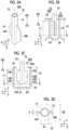
- the perforating tool 10 shown in Figs. 3A, 3B, and 3C is a perforating tool capable of perforating the sealing film that seals the opening portion of the container which accommodates the liquid. That is, the perforating tool 10 is a perforating tool capable of perforating the sealing film 32 that seals the opening portions 20A, 22A, 24A, 26A, and 28A which are formed in the accommodating portions 20, 22, 24, 26, and 28 of the cartridge RC shown in Fig. 1 .
- the perforating tool 10 according to the present example is provided in a dispensing mechanism provided in the above-mentioned immunological analysis apparatus (not shown in the drawing).
- the drive unit M is a drive unit of the dispensing mechanism.
- the drive unit M moves the perforating tool 10 in the up-down direction by a predetermined stroke in the immunological analysis apparatus.
- the drive unit M inserts the perforating tool 10 into each of the accommodating portions 20, 22, 24, 26, and 28 of the cartridge RC loaded into the immunological analysis apparatus, or pulls out the perforating tool 10 from each of the accommodating portions 20, 22, 24, 26, and 28.
- the perforating tool 10 according to the present example also has a function of the nozzle, the perforating tool 10 suctions and discharges the liquid in each of the accommodating portions 20, 22, 24, 26, and 28.
- the perforating tool 10 includes a rod-shaped shaft portion 12 extending from a front end side FS that pierces the sealing film 32 to a base end side RS, and a large diameter portion 14 formed at a front end portion of the shaft portion 12.
- the shaft portion 12 has a tubular shape which has a circular cross section orthogonal to an axial direction of the shaft portion 12.
- the shaft portion 12 has a pipe line 12A which is formed therein and through which a liquid flows, and functions as the nozzle that suctions and discharges the liquid as described above.
- an edge surface of the shaft portion 12 on the front end side is formed as a surface orthogonal to the axial direction of the shaft portion 12.
- Figs. 3A to 3D each show a central line of the shaft portion 12 as a central line CL.
- the "axial direction" of the shaft portion 12 is a direction along the central line CL.
- the large diameter portion 14 protrudes in a radial direction of the shaft portion 12 and is formed of two plate-like portions 14A and 14B in which plate surfaces extend in the axial direction of the shaft portion 12.
- the "radial direction" of the shaft portion 12 is a direction orthogonal to the axial direction of the shaft portion 12 and a direction intersecting with the central line CL.
- the plate-like portions 14A and 14B are formed at positions which are symmetric with respect to the shaft portion 12 as a center.
- a pair of plate-like portions 14A and 14B have shapes of blades protruding on both sides in the radial direction from the shaft portion 12. Further, as shown in Fig. 3D , a thickness t1 of the plate-like portions 14A and 14B is less than a diameter R1 of the shaft portion 12.
- front end side parts 14C of the plate-like portions 14A and 14B have a shape in which the width in the radial direction of the shaft portion 12 is reduced from the base end side RS toward the front end side FS.
- the front end positions of the plate-like portions 14A and 14B in the axial direction of the shaft portion 12 match the front end position of the shaft portion 12.
- base end side parts 14D of the plate-like portions 14A and 14B each have a shape in which the width in the radial direction of the shaft portion 12 decreases from the front end side FS toward the base end side RS.
- a width of a part between the front end side part 14C and the base end side part 14D of each of the plate-like portions 14A and 14B, that is, a width of the central side part 14E of each of the plate-like portions 14A and 14B, in the radial direction of the shaft portion 12 is constant along the axial direction of the shaft portion 12.
- each of the plate-like portions 14A and 14B is formed in a trapezoidal shape in which a long bottom side thereof is bonded to the shaft portion 12 and a short bottom side thereof is disposed at a position separated from the shaft portion 12, as viewed from a normal direction of the surfaces of the plate-like portions 14A and 14B (that is, as viewed in front of the plate-like portions 14A and 14B).
- a diameter R2 of a circumcircle which circumscribes an outer shape of a cross section of the large diameter portion 14 formed of the plate-like portions 14A and 14B is greater than a diameter R1 of a circumcircle which circumscribes an outer shape of a cross section of the shaft portion 12.
- the "cross section" of the large diameter portion 14 and the “cross section” of the shaft portion 12 are cross sections orthogonal to the axial direction of the shaft portion 12, and are cross sections (parts indicated by the hatching in Fig. 3D ) which are cut by the line D-D in Figs. 3B and 3C .
- the diameter of the circumcircle circumscribing the outer shape greater than that of the comparison target is referred to as a "large diameter". That is, the outer shape of the cross section of the large diameter portion 14 is not always circular, and the diameter of the large diameter is a diameter of the circumcircle.
- the outer shape of the cross section of the shaft portion 12 other than the large diameter portion 14, that is, the outer shape of the cross section of the shaft portion 12 in a part, in which the plate-like portions 14A and 14B are not provided, is circular, and the circumcircle thereof matches the outer shape of the cross section of the shaft portion 12. Consequently, the large diameter of the large diameter portion 14 means that the large diameter is greater than the comparison target in a case where the diameter of the outer shape of the cross section of the shaft portion 12 is used as the comparison target.
- a length L1 from the front end of the shaft portion 12, that is, the front end of the perforating tool 10, to the end portion of the large diameter portion 14 on the base end side RS is shorter than a maximum insertion depth L2 with respect to the accommodating portion (for example, the accommodating portion 24) of the shaft portion 12.
- the "maximum insertion depth” refers to a maximum value of an insertion amount of the perforating tool 10 to be inserted into the accommodating portion 24 in a case of performing suction or discharge.
- the maximum insertion depth is a value determined by setting a stroke of the drive unit M (refer to Fig.
- the meaning of defining of the maximum insertion depth L2 is that, in a case where the perforating tool 10 is inserted into the accommodating portion 24, it is necessary that the entire large diameter portion 14 enters the accommodating portion 24 and the upper end of the large diameter portion 14 is positioned under the sealing film 32.
- the maximum insertion depth L2 changes in accordance with the depth of the accommodating portion.
- the maximum insertion depth L2 and the length L1 are determined in accordance with the accommodating portion having the shallowest depth.
- the accommodating portion into which the perforating tool 10 or the perforating tool according to various modification examples is inserted, may be described as an example of the "accommodating portion 24", but this is for convenience and the accommodating portion 24 is just an example.
- the accommodating portion, into which the perforating tool 10 or the perforating tool according to various modification examples is inserted, may be any of the accommodating portions 20, 22, 24, 26, and 28.
- Figs. 4A and 5 show a comparative example.
- the comparative example will be described with reference to Figs. 4A and 5 .
- the actions and effects of the perforating tool 10 according to the present example will be described with reference to Figs. 6A and 7B in comparison with the comparative example.
- a perforating tool 500 of the "comparative example” does not have a large diameter portion formed therein, and the diameter of the shaft portion is constant in a range from the front end side to the base end side.
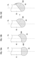
- the sealing film 32 is pressed by the front end of the perforating tool 500, and as shown in Fig. 4C , the perforating tool 500 pierces the sealing film 32. Therefore, a through-hole 32T having a diameter close to the diameter of the shaft portion of the perforating tool 500 is opened in the sealing film 32.
- the luminescent reagent K3 hereinafter, referred to as a liquid K3 in the accommodating portion 24 is attached to the rear surface of the sealing film 32.
- the liquid K3 attached to the rear surface of the sealing film 32 encircles a gap between the through-hole 32T and the perforating tool 500, and the liquid K3 enters the gap.
- a diameter of the perforating tool 500 and a diameter of the through-hole 32T are approximate to each other, that is, in a case where a gap width between the perforating tool 500 and an inner edge of the through-hole 32T is narrow, the liquid K3 is held so as to clog the gap.
- the diameter of the shaft portion is constant as in the case of the perforating tool 500 according to the comparative example, even though the insertion amount of the perforating tool 500 is large, the state where the gap width is narrow does not change, and the state where the liquid K3 clogs the gap continues.
- the pressure in the accommodating portion 24 increases due to the insertion of the perforating tool 500 into the accommodating portion 24, and the air in the accommodating portion 24 is about to be ejected to the outside of the accommodating portion 24 from the gap between the through-hole 32T and the perforating tool 500.
- the internal pressure increases, and the pressure, at which the air in the accommodating portion 24 is about to be ejected to the outside of the accommodating portion 24 through the gap, also increases.
- the air in the accommodating portion 24 is eventually ejected to the outside of the container together with the liquid K3 that clogs the gap. Due to such a mechanism, the liquid K3 held in the gap between the through-hole 32T and the perforating tool 500 may be ejected to the outside of the accommodating portion 24, and the liquid K3 may be scattered around the through-hole 32T.
- the pressure is also increased due to the temperature increase. Thus, the ejection amount tends to be further increased.
- the sealing film 32 may be pulled by the perforating tool 500 through a frictional force between the inner edge of the through-hole 32T and the perforating tool 500, and a state where the circumference of the through-hole 32T protrudes to the outside of the accommodating portion 24 may occur.
- the liquid K3 attached to the rear surface of the sealing film 32 around the through-hole 32T may be ejected and scattered to the outside of the accommodating portion 24 from the through-hole 32T.
- an environment in which the cartridge RC (refer to Fig. 1 ) is disposed may be contaminated.
- the liquid K4 the labeling reagent K4: hereinafter, referred to as a liquid K4
- the two liquids are mixed outside the accommodating portions 24 and 26.
- the mixed liquid may be attached to the perforating tool 500.
- each of the liquids is used individually to perform the examination, another liquid is mixed into each of the liquids. Therefore, unintended contamination between liquids occurs, which may affect the examination results. Further, even in a case where each of the liquids is quantitatively mixed and the examination is performed, an error occurs in an amount of mixture, which may affect the examination results.
- the large diameter portion 14 is formed at the front end portion of the shaft portion 12.
- the diameter R2 of the circumcircle of the traverse cross section orthogonal to the axial direction of the shaft portion 12 is greater than the diameter R1 of the circumcircle of the traverse cross section of the shaft portion 12.
- the sealing film 32 is perforated using the perforating tool 10.
- the front end of the perforating tool 10 presses the sealing film 32.
- the perforating tool 10 is pierced into the sealing film 32. Therefore, a through-hole 32S is opened in the sealing film 32.
- the sealing film 32 is perforated by the large diameter portion 14 formed in the shaft portion 12 and the front end portion of the shaft portion 12, and the through-hole 32S is formed in the sealing film 32.
- An area of the through-hole 32S is greater than an area of the traverse cross section 12S of the shaft portion 12, and is further greater than an area of the traverse cross section 14S of the large diameter portion 14.
- the through-hole 32S is formed by connecting a part that is formed by being perforated by the shaft portion 12 and a part that is formed by being perforated by the large diameter portion 14.
- the through-hole 32S tends to be formed to connect positions that are most distant from a central point O of the shaft portion 12 in the outer circumferential portions of the shaft portion 12 and the large diameter portion 14 as shown in Fig. 7B . That is, by using the perforating tool 10, the through-hole having the large diameter can be formed as compared with the perforating tool 500 according to the comparative example in which the large diameter portion 14 is not formed.
- the accommodating portion 24 accommodates the entire large diameter portion 14, and the shaft portion 12 in which the large diameter portion 14 is not provided reaches the position of the sealing film 32, a gap between the perforating tool 10 and the inner edge of the through-hole 32S is increased.
- the shaft portion 12 has a smaller diameter than the large diameter portion 14. Therefore, the gap is greater than that in a case where the perforating tool 500 according to the comparative example in which the large diameter portion 14 is not formed is used. Thereby, the liquid K3 inside the accommodating portion 24 is unlikely to be held in the gap.
- the perforating tool 10 even if the liquid is attached to the rear surface of the sealing film 32, it is possible to suppress the liquid from being scattered to the outside of the accommodating portion 24 in a case where the sealing film 32 that seals the opening portion 24A of the accommodating portion 24 which accommodates the liquid is perforated.
- the large diameter portion 14 is formed of plate-like portions 14A and 14B that protrude in the radial direction of the shaft portion 12 and that have a plate surface extending in the axial direction.
- the large diameter portion 14 is formed by the plate-like portions 14A and 14B protruding in the radial direction of the shaft portion 12. Therefore, as shown in Figs. 7A and 7B , the through-hole 32S extending from the shaft portion 12 to the plate-like portions 14A and 14B is formed in the sealing film 32. That is, the through-hole 32S can be formed to a position away from the shaft portion 12. Therefore, for example, in a case where the perforating tool 10 is pulled out from the accommodating portion 24, it is possible to suppress the liquid attached to the shaft portion 12 from being filled in the through-hole 32S.
- the plate-like portions 14A and 14B forming the large diameter portion 14 are formed in a plurality of pieces (that is, two pieces) at positions which are symmetric with respect to the shaft portion 12 as a center.
- a plurality of (that is, two) gaps are formed in the sealing film 32 at positions which are symmetric with respect to the shaft portion 12 as a center. Therefore, even in a case where the liquid is biased and is attached to the rear surface of the sealing film 32, it is easy to ensure an air passage in any of the gaps.
- the thickness t1 of the plate-like portions 14A and 14B is less than the outer diameter (diameter R1) of the shaft portion 12.
- the thickness t1 of the plate-like portions 14A and 14B is less than the outer diameter (diameter R1) of the shaft portion 12. Therefore, the pressure acting on the sealing film 32 per unit area can be increased in a case where the sealing film 32 is pressed with the same force as compared with a case where the thickness t1 of the plate-like portions 14A and 14B is equal to or greater than the outer diameter (diameter R1) of the shaft portion 12. Therefore, the sealing film 32 is easily perforated.
- front end side parts 14C of the plate-like portions 14A and 14B each have a shape in which the width of the front end side parts 14C in the radial direction of the shaft portion 12 is reduced from the base end side RS of the shaft portion 12 toward the front end side FS. That is, the front ends of the plate-like portions 14A and 14B are pointed. Therefore, the sealing film 32 is easily perforated.
- the width of the plate-like portion is a constant width, a resistivity that is applied to the perforating tool 10 by the sealing film 32 during the perforation of the sealing film 32 is large. Thus, it is difficult to perforate the sealing film 32.
- base end side parts 14D of the plate-like portions 14A and 14B each have a shape in which the width of the base end side parts 14D in the radial direction of the shaft portion 12 is reduced from the front end side FS of the shaft portion 12 toward the base end side RS. That is, the rear ends of the plate-like portions 14A and 14B are pointed. Therefore, the plate-like portions 14A and 14B can be easily inserted into the large diameter through-hole 32S formed by the central side part 14E, and the perforating tool 10 can be easily pulled out.
- the width of the plate-like portion is a constant width
- the plate-like portion is likely to be caught by the opening end of the through-hole 32S, and it is difficult to pull out the perforating tool 10 from the inside of the accommodating portion 24.
- the shaft portion 12 has a pipe line which is formed therein and through which the liquid flows, and functions as the nozzle through which the liquid is suctioned and discharged.
- the perforating tool 10 is used, scattering of the liquid to the outside of the accommodating portion 24 is suppressed. Therefore, it is possible to suppress the liquid outside the accommodating portion 24 from being mixed with the liquid inside the perforating tool 10 which is the nozzle.
- the front end surface which is an edge surface of a shaft portion 42 on the front end side FS, has an inclined surface 42A which is inclined with respect to the base end side RS in a direction orthogonal to the axial direction of the shaft portion 42, the inclined surface 42A forming an acute angle ⁇ 1 with a straight line (central line CL) extending in the axial direction.
- the front end surface of the shaft portion 42 has an orthogonal surface 42B that is connected to the inclined surface 42A and that is orthogonal to the axial direction, in addition to the inclined surface 42A.
- Configurations of the plate-like portions 44A and 44B that form the large diameter portion 44 in the perforating tool 40 are the same as configurations of the plate-like portions 14A and 14B in the perforating tool 10.
- the front end position of the plate-like portion 44A in the axial direction of the shaft portion 42 coincides with a position of the orthogonal surface 42B.
- the front end position of the plate-like portion 44B in the axial direction of the shaft portion 42 coincides with a position of the base end side edge portion of the inclined surface 42A.
- the front end surface which is an edge surface of the shaft portion 42 on the front end side, has the above-mentioned inclined surface 42A. That is, the front end surface has a shape in which the width gradually decreases in the radial direction from the base end side RS toward the front end side FS of the shaft portion 42. That is, the front end surface of the shaft portion 42 is sharper than that in a case where the inclined surface 42A is not provided. Therefore, the sealing film 32 is easily perforated.
- the front end surface which is an edge surface of a shaft portion 52 on the front end side FS, has an inclined surface 52A which is inclined with respect to the base end side RS in a direction orthogonal to the axial direction of the shaft portion 52, the inclined surface 52A forming an acute angle ⁇ 2 with the straight line (central line CL) extending in the axial direction.
- the front end surface is formed of only the inclined surface 52A.
- Configurations of the plate-like portions 54A and 54B that form the large diameter portion 54 in the perforating tool 50 are the same as configurations of the plate-like portions 14A and 14B in the perforating tool 10.
- the front end position of the plate-like portion 54A in the axial direction of the shaft portion 52 coincides with a position of the front end side edge portion of the inclined surface 52A.
- the front end position of the plate-like portion 54B in the axial direction of the shaft portion 52 coincides with a position of the base end side edge portion of the inclined surface 52A.
- the front end surface of the shaft portion 52 is composed of only the inclined surface 52A.
- the front end surface of the shaft portion 52 is formed obliquely with respect to a surface orthogonal to the axial direction of the shaft portion 52.
- the corner portion 50E having an acute angle formed by the inclined surface 52A and the side surface, which is the edge surface of the shaft portion 52 comes into contact with the surface of the sealing film 32 (refer to Fig. 1A). That is, the inclined surface 52A and the sealing film 32 are in contact with each other to be close to point contact.
- the contact area with the sealing film 32 is less than that in a case where the front end surface of the shaft portion is formed of the "orthogonal surface which is orthogonal to the axial direction".
- the pressure acting on the sealing film 32 per unit area can be increased in a case where the sealing film 32 is pressed with the same force.
- the front end surface of the shaft portion 42 is formed to be sharper. Therefore, an effect of easily perforating the sealing film 32 is enhanced.
- Fig. 10A shows the shaft portion 12 of the perforating tool 10 in which the front end surface is formed of only the "orthogonal surface which is orthogonal to the axial direction".
- Fig. 10B shows the shaft portion 42 of the perforating tool 40 in which the inclined surface 42A and the orthogonal surface 42B are formed on the front end surface.
- Fig. 10C shows the shaft portion 52 of the perforating tool 50 of which the front end surface is the inclined surface 52A. It should be noted that Figs. 10A to 10C does not show the plate-like portion.
- the liquid (for example, the liquid K3) attached to the end surface is formed to be offset from the central line CL of the shaft portion to the side surface of the shaft portion.
- a liquid droplet may be formed on the edge surface of the shaft portion 52, that is, the inclined surface 52A.
- the liquid attached to the edge surface is formed by being offset from the central line CL of the shaft portion to the side surface side, the liquid is likely to encircle the side surface of the shaft portion.
- the entire amount of the liquid droplet may not drop, and the liquid may remain in the shaft portion 52 in a case where the liquid is discharged from the shaft portion 52 which is the nozzle.
- the liquid droplet is formed on the inclined surface 42A and the orthogonal surface 42B of the shaft portion 42 shown in Fig. 10B .
- the liquid is unlikely to encircle the side surface of the shaft portion as compared with the shaft portion 52 in which the orthogonal surface is not formed. Therefore, in a case where the liquid is discharged from the shaft portion 42, the liquid can be easily used without waste.
- the shaft portion 12 shown in Fig. 10A is easier to use the liquid without waste than the shaft portion 42.
- a perforating tool 60 according to a modification example shown in Figs. 11A and 11B includes a shaft portion 62 and plate-like portions 64A and 64B having the same configurations as the shaft portion 12 and the plate-like portions 14A and 14B in the perforating tool 10, but is different from the perforating tool 10 in the following points.
- front ends of the plate-like portions 64A and 64B forming a large diameter portion 64 are disposed at positions which are offset from a front end surface of the shaft portion 62 toward the base end side.
- Fig. 12A shows the shaft portion 12 and the plate-like portions 14A and 14B of the perforating tool 10.
- the front ends of the plate-like portions 14A and 14B coincide with the positions of the front end surfaces of the shaft portion 12. Therefore, the liquid attached to the edge surface of the shaft portion 12 is likely to encircle the plate-like portions 14A and 14B.
- Fig. 12B shows the shaft portion 62 and the plate-like portions 64A and 64B of the perforating tool 60.
- the front ends of the plate-like portions 64A and 64B are disposed at positions which are offset from the front end surface of the shaft portion 62 toward the base end side. Therefore, the liquid attached to the edge surface of the shaft portion 62 is unlikely to encircle the plate-like portions 64A and 64B. Thereby, in the perforating tool 60, in a case where the liquid is discharged from the shaft portion 62, it is possible to suppress the liquid droplet from encircling the plate-like portions 64A and 64B and remaining as liquid.
- a perforating tool 70 similarly to the perforating tool 60 shown in Figs. 11A and 11B , front ends of plate-like portions 74A and 74B forming a large diameter portion 74 are disposed at positions which are offset from a front end surface of a shaft portion 72 toward the base end side.
- the front end surface which is an edge surface of the shaft portion 72 on the front end side FS, has an inclined surface 72A which is inclined with respect to the base end side RS in a direction orthogonal to the axial direction of the shaft portion 72, the inclined surface 72A forming an acute angle ⁇ 3 with the straight line (central line CL) extending in the axial direction.
- the front end surface of the shaft portion 72 has an orthogonal surface 72B that is connected to the inclined surface 72A and that is orthogonal to the axial direction, in addition to the inclined surface 72A.
- a perforating tool 80 similarly to the perforating tool 60 shown in Figs. 11A and 11B , front ends of plate-like portions 84A and 84B forming a large diameter portion 84 are disposed at positions which are offset from a front end surface of a shaft portion 82 toward the base end side.
- the front end surface which is an edge surface of the shaft portion 82 on the front end side FS, has an inclined surface 82A which is inclined with respect to the base end side RS in a direction orthogonal to the axial direction of the shaft portion 82, the inclined surface 82A forming an acute angle ⁇ 4 with the straight line (central line CL) extending in the axial direction.
- the front end surface of the shaft portion 82 is formed only on the inclined surface 52A.
- the front end side parts 14C of the plate-like portions 14A and 14B each have a shape in which the width in the radial direction of the shaft portion 12 is reduced from the base end side RS toward the front end side FS.
- the base end side parts 14D of the plate-like portions 14A and 14B each have a shape in which the width in the radial direction of the shaft portion 12 is reduced from the front end side FS toward the base end side RS, but the embodiment of the present disclosure is not limited thereto.
- the plate-like portions may be configured to have the "same width" along the axial direction of the shaft portion. That is, the plate-like portion may have a rectangular shape or a square shape in the front view. Even with such a shape, it is possible to suppress the scattering of the liquid to the outside of the accommodating portion 24 in a case of perforating the sealing film 32 that seals the opening portion 24A of the accommodating portion 24 which accommodates the liquid. Further, in a case where the plate-like portions have the same width along the axial direction of the shaft portion, the plate-like portions are easily manufactured.
- the front end side part 14C of the plate-like portion may have a shape in which the width decreases from the base end side RS toward the front end side FS.
- the base end side part 14D of the plate-like portion may have a shape in which the width decreases from the front end side FS toward the base end side RS.
- the plate-like portion may have a shape in which the width decreases from the base end side RS toward the front end side FS or a shape in which the width decreases from the front end side FS toward the base end side RS over the entire length of the shaft portion 12 in the axial direction.
- the large diameter portion 14 is formed of the two plate-like portions 14A and 14B, but the embodiment of the present disclosure is not limited thereto.
- the large diameter portion may be formed of one plate-like portion or may be formed of three or more plate-like portions. That is, in each embodiment in which the large diameter portion is formed of a plate-like portion, the number of plate-like portions is not particularly limited. In a case where the number of plate-like portions is reduced, it is easy to form the large diameter portion. In a case where the number of plate-like portions is increased, it is possible to form a large number of gaps around the shaft portion.
- the large diameter portion is formed of a plurality of plate-like portions, it is preferable that the plate-like portions are arranged at equal intervals in a circumferential direction of the shaft portion.
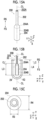
- a perforating tool 200 shown in Figs. 15A to 15C is a perforating tool capable of perforating a sealing film for sealing an opening portion of a container accommodating a liquid, as in each perforating tool according to the first embodiment. That is, the perforating tool 200 is a perforating tool capable of perforating the sealing film 32 that seals the opening portions 20A, 22A, 24A, 26A, and 28A which are formed in the accommodating portions 20, 22, 24, 26, and 28 of the cartridge RC shown in Fig. 1 .
- the perforating tool 200 includes a rod-shaped shaft portion 202 extending from a front end side FS that pierces the sealing film 32 to a base end side RS, and a tubular portion 204 formed at a front end portion of the shaft portion 202 as a large diameter portion.
- the shaft portion 202 has a tubular shape which has a circular cross section orthogonal to the axial direction of the shaft portion 202, and a pipe line 202A, through which a liquid flows, is formed in the shaft portion 202. Therefore, the shaft portion 202 functions as a nozzle for suctioning and discharging the liquid.
- the tubular portion 204 is a tubular portion which has a circular cross-sectional shape orthogonal to the axial direction. Further, the tubular portion 204 has a shape similar to the shaft portion 202 and has a shape in which the diameter of the shaft portion 202 is increased. That is, a rear end side part 204A of the tubular portion 204 has a tapered shape that gradually increases in diameter from the base end side RS toward the front end side FS of the shaft portion 202. A front end side part 204B is connected to the front end of the rear end side part 204A. The front end side part 204B is formed in a tubular shape having a diameter which is identical along the axial direction of the shaft portion 202.
- the tubular portion 204 that is, the front end of the front end side part 204B is formed to be orthogonal to the axial direction of the shaft portion 202.
- the term "similar shape" indicates that the outer shapes of the shaft portion 202 and the tubular portion 204 are similar to each other. Wall thicknesses of the shaft portion 202 and the tubular portion 204 may be different from each other or may be the same as each other.
- a diameter R4 of a circumcircle which circumscribes an outer shape of a cross section of the tubular portion 204 is greater than a diameter R3 of a circumcircle which circumscribes an outer shape of a cross section of the shaft portion 202.
- the "cross section" of the tubular portion 204 and the “cross section” of the shaft portion 202 are cross sections orthogonal to the axial direction of the shaft portion 202 and are cross sections which are cut along the line C-C in Fig. 15B .
- a length L3 from the front end of the shaft portion 202, that is, the front end of the perforating tool 200, to the end portion on the base end side RS of the tubular portion 204 which is the large diameter portion is shorter than a maximum insertion depth L4 of the shaft portion 202 with respect to the accommodating portion 24.
- the tubular portion 204 is a part of the shaft portion 202, and the "front end of the shaft portion 202" indicates the front end of the tubular portion 204.
- the tubular portion 204 as the large diameter portion is formed at the front end portion of the shaft portion 202.
- the diameter R4 of the circumcircle of the traverse cross section of the tubular portion 204 orthogonal to the axial direction of the shaft portion 202 is greater than the diameter R3 of the circumcircle of the traverse cross section of the shaft portion 202.
- the reason for this is that, in a case where the insertion amount of the perforating tool 200 into the accommodating portion 24 is increased, the accommodating portion 24 accommodates the entire tubular portion 204, and the shaft portion 202 in which the tubular portion 204 is not provided reaches the position of the sealing film 32, a gap between the perforating tool 200 and the inner edge of the through-hole 32S is increased.
- the shaft portion 202 has a smaller diameter than the tubular portion 204. Therefore, a gap between the shaft portion 202 and the inner edge of the through-hole 32S is greater than a gap between the tubular portion 204 and the inner edge of the through-hole 32S.
- the gap is large even in comparison with a case where the perforating tool 500 according to the comparative example in which the diameter of the shaft portion is constant in a range from the front end side to the base end side is used. Thereby, the liquid K3 inside the accommodating portion 24 is unlikely to be held in the gap.
- the large diameter portion is the tubular portion 204 having the circular cross-sectional shape orthogonal to the axial direction. That is, as in a case where the large diameter portion is a plate-like portion protruding in the radial direction of the shaft portion, there is no plate-like member protruding to the outside of a tubular member. Therefore, the perforating tool 200 is less likely to be caught by any member which is disposed around the perforating tool.
- the tubular portion 204 which is the large diameter portion, has a shape similar to the shaft portion 202 and has a shape in which the diameter of the shaft portion 202 is increased.
- the tubular portion 204 has a shape similar to the shaft portion 202. Therefore, in a case where the perforating tool 200 is inserted into the accommodating portion 24 and the shaft portion 202 is disposed in the through-hole 32S, a gap having a uniform width is likely to be formed around the shaft portion 202. Thereby, even in a case where the liquid is biased and is attached to the rear surface of the sealing film 32, the gap is likely to be formed in a part to which the liquid is not attached. Therefore, the air passage is likely to be ensured.
- the diameter of the shaft portion 202 is increased in the tubular portion 204. Therefore, a cross-sectional area of the tubular portion 204 is greater than that of the shaft portion 202. Therefore, a strength of the tubular portion 204 that is likely to be loaded in a case of perforating the sealing film 32 is greater than that of the other part. Therefore, the perforating tool 200 is unlikely to be damaged, and thus maintenance is easy.
- a perforating tool 210 according to a modification example shown in Fig. 16A includes a shaft portion 212 and a tubular portion 214.
- the perforating tool 210 is different from the perforating tool 200 in the following points.
- a front end surface which is an edge surface of the tubular portion 214 on the front end side FS, is an inclined surface 214A which is inclined toward the base end side RS with respect to a direction orthogonal to the axial direction of the shaft portion 212, the inclined surface 214A forming an acute angle ⁇ 5 with the straight line (central line CL) extending in the axial direction.
- the front end surface of the tubular portion 214 has an orthogonal surface 214B that is connected to the inclined surface 214A and that is orthogonal to the axial direction, in addition to the inclined surface 214A.
- a perforating tool 220 according to a modification example shown in Fig. 16B includes a shaft portion 222 and a tubular portion 224.
- the perforating tool 220 is different from the perforating tool 200 in the following points.
- the front end surface which is an edge surface of the tubular portion 214 on the front end side FS, has an inclined surface 224A which is inclined toward the base end side RS with respect to the direction orthogonal to the axial direction of the shaft portion 212, the inclined surface 224A having an acute angle ⁇ 6 with the straight line (central line CL) extending in the axial direction.
- the front end surface is formed of only the inclined surface 224A.
- a perforating tool 230 according to a modification example shown in Fig. 17A includes a shaft portion 232 and a tubular portion 234.
- the perforating tool 230 is different from the perforating tool 200 in the following points.
- the shaft portion 232 is inserted into the tubular portion 234.
- the perforating tool 230 has a double pipe formed of the shaft portion 232 that is a straight pipe having the same cross-sectional shape over the axial direction and the tubular portion 234 that covers an outer circumference of the shaft portion 232.
- the tubular portion 234 has an end portion on the base end side RS that is reduced in diameter from the front end side FS toward the base end side RS and that is bonded to the shaft portion 232.
- the perforating tool 230 having such a double pipe structure can be formed, for example, by separately manufacturing the shaft portion 232 and the tubular portion 234 and cementing the shaft portion 232 and the tubular portion 234. Therefore, it is easy to form the large diameter portion.
- the large diameter portion is formed by the tubular portion in which the diameter of the shaft portion is increased, it is necessary for the large diameter portion to be formed by cutting, squeezing, or the like. Thus, it is difficult to form the large diameter portion.
- the liquid suctioned into the accommodating portion 24 is discharged to the outside of the accommodating portion 24 using the perforating tool 230 as a nozzle, the liquid is discharged through the inside of the shaft portion 232, which is a straight pipe, to the outside of the accommodating portion 24. Therefore, turbulence or the like is unlikely to occur in a case where the liquid passes through the large diameter portion, and the discharging performance is stable.
- the large diameter portion is formed by the tubular portion in which the shaft portion is enlarged in diameter, a bent portion is formed in the pipe line at the enlarged-diameter part.
- unevenness may be formed in the enlarged-diameter part.
- the bent portion or unevenness is present on an inner surface of a pipe line that handles the liquid, turbulence is likely to occur in the pipe line, or dirt is likely to be attached to the pipe line.
- a measure of polishing the inner surface of the pipe line can be used, but such a measure is not always sufficient, and it takes time to produce.
- the perforating tool 230 By forming the perforating tool 230 to have the double pipe structure, it is less necessary to polish the inner surface of the pipe line. Even in a case where the inner surface of the pipe line is polished, the polishing work is easy.
- a perforating tool 240 according to a modification example shown in Fig. 17B includes a shaft portion 242 and a tubular portion 244.
- the perforating tool 240 is different from the perforating tool 230 in the following points.
- a front end surface which is an edge surface of the shaft portion 242 on the front end side FS, has an inclined surface 242A which is inclined with respect to the base end side RS in a direction orthogonal to the axial direction of the shaft portion 242, the inclined surface 242A forming an acute angle ⁇ 6 with the straight line (central line CL) extending in the axial direction.
- the front end surface of the shaft portion 242 has an orthogonal surface 242B that is connected to the inclined surface 242A and that is orthogonal to the axial direction, in addition to the inclined surface 242A.
- the front end surface which is an edge surface of the tubular portion 244 on the front end side FS, has an inclined surface 244A which is inclined with respect to the base end side RS in a direction orthogonal to the axial direction of the tubular portion 244, the inclined surface 244A forming an acute angle ⁇ 6 with the straight line (central line CL) extending in the axial direction.
- the front end surface of the tubular portion 244 has the orthogonal surface 244B that is connected to the inclined surface 244A and that is orthogonal to the axial direction, in addition to the inclined surface 244A.
- the inclined surfaces 242A and 244A are surfaces formed on the same plane, and the orthogonal surfaces 242B and 244B are also surfaces formed on the same plane.
- the inclined angles of the inclined surfaces 242A and 244A are set to the same acute angle ⁇ 6, but may be different angles.
- at least one of the inclined surfaces 242A or 244A may be formed. That is, in any one of the shaft portion 242 or the tubular portion 244, the front end surface may be formed of only an orthogonal surface which is orthogonal to the axial direction.
- a perforating tool 250 according to a modification example shown in Fig. 17C includes a shaft portion 252 and a tubular portion 254.
- the perforating tool 250 is different from the perforating tool 230 in the following points.
- a front end surface which is an edge surface of the shaft portion 252 on the front end side FS, has an inclined surface 252A which is inclined with respect to the base end side RS in a direction orthogonal to the axial direction of the shaft portion 252, the inclined surface 252A forming an acute angle ⁇ 7 with the straight line (central line CL) extending in the axial direction.
- the front end surface is formed of only the inclined surface 252A.
- the front end surface which is an edge surface of the tubular portion 254 on the front end side FS, has an inclined surface 254A which is inclined with respect to the base end side RS in a direction orthogonal to the axial direction of the tubular portion 254, the inclined surface 254A forming an acute angle ⁇ 7 with the straight line (central line CL) extending in the axial direction.
- the front end surface is formed of only the inclined surface 254A.
- the inclined surfaces 252A and 254A are surfaces formed on the same plane.
- the inclined angles of the inclined surfaces 252A and 254A are set to the same acute angle ⁇ 7, but may be set to different angles.
- at least one of the inclined surfaces 252A or 254A may be formed. That is, in any one of the shaft portion 252 or the tubular portion 254, the front end surface may be formed of only an orthogonal surface which is orthogonal to the axial direction.
- a perforating tool 260 according to a modification example shown in Fig. 18A includes a shaft portion 262 and a tubular portion 264.
- the perforating tool 260 is different from the perforating tool 230 in the following points.
- the front end of the tubular portion 264 is disposed at a position which is offset from the front end surface of the shaft portion 262 toward the base end side.
- a perforating tool 270 according to a modification example shown in Fig. 18B includes a shaft portion 272 and a tubular portion 274.
- the perforating tool 270 is different from the perforating tool 230 in the following points.
- the front end of the tubular portion 274 is disposed at a position which is offset from the front end surface of the shaft portion 272 toward the base end side.
- the front end surface which is an edge surface of the shaft portion 272 on the front end side FS, has an inclined surface 272A which is inclined with respect to the base end side RS in a direction orthogonal to the axial direction of the shaft portion 272, the inclined surface 272A forming an acute angle ⁇ 8 with the straight line (central line CL) extending in the axial direction.
- the front end surface of the shaft portion 272 has an orthogonal surface 272B that is connected to the inclined surface 272A and that is orthogonal to the axial direction, in addition to the inclined surface 272A.
- the front end surface which is an edge surface of the tubular portion 274 on the front end side FS, has an inclined surface 274A which is inclined with respect to the base end side RS in a direction orthogonal to the axial direction of the tubular portion 274, the inclined surface 274A forming an acute angle ⁇ 8 with the straight line (central line CL) extending in the axial direction.
- the front end surface of the tubular portion 274 has an orthogonal surface 274B that is connected to the inclined surface 274A and that is orthogonal to the axial direction, in addition to the inclined surface 274A.
- a perforating tool 280 according to a modification example shown in Fig. 18C includes a shaft portion 282 and a tubular portion 284.
- the perforating tool 280 is different from the perforating tool 230 in the following points.
- the front end of the tubular portion 284 is disposed at a position which is offset from a front end surface of the shaft portion 282 toward the base end side.
- the front end surface which is an edge surface of the shaft portion 282 on the front end side FS, has an inclined surface 282A which is inclined with respect to the base end side RS in a direction orthogonal to the axial direction of the shaft portion 282, the inclined surface 282A forming an acute angle ⁇ 9 with the straight line (central line CL) extending in the axial direction.
- the front end surface is formed of only the inclined surface 282A.
- the front end surface which is an edge surface of the tubular portion 284 on the front end side FS, has an inclined surface 284A which is inclined with respect to the base end side RS in a direction orthogonal to the axial direction of the tubular portion 284, the inclined surface 284A forming an acute angle ⁇ 9 with the straight line (central line CL) extending in the axial direction.
- the front end surface is formed of only the inclined surface 284A.
- the tubular portion has a similar shape to the shaft portion.
- the embodiment of the present disclosure is not limited thereto.
- the tubular portion may have a polygonal shape or an elliptical shape.
- the perforating tool may be a tool capable of perforating the sealing film 32.
- the perforating tool 10 can be used for another container which is capable of accommodating the liquid.
- the present disclosure is not limited to the above-mentioned embodiments, and can be implemented with appropriate modifications, such as omitting a configuration or replacing a configuration with a different configuration within the scope that does not deviate from the gist of the present disclosure.
- JP2022-045776 filed on March 22, 2022 is incorporated herein by reference in its entirety.
Landscapes
- Life Sciences & Earth Sciences (AREA)
- Forests & Forestry (AREA)
- Engineering & Computer Science (AREA)
- Mechanical Engineering (AREA)
- Physics & Mathematics (AREA)
- Health & Medical Sciences (AREA)
- Chemical & Material Sciences (AREA)
- Analytical Chemistry (AREA)
- Biochemistry (AREA)
- General Health & Medical Sciences (AREA)
- General Physics & Mathematics (AREA)
- Immunology (AREA)
- Pathology (AREA)
- Containers And Packaging Bodies Having A Special Means To Remove Contents (AREA)
- Devices For Opening Bottles Or Cans (AREA)
Abstract
Description
- The technique of the present disclosure relates to a perforating tool.
- A liquid container that is used for examining a specimen and includes a well-like accommodating portion that accommodates a liquid such as a reagent and a sealing film that seals an opening portion formed in an upper portion of the accommodating portion is known. In such a liquid container, the sealing film is perforated by piercing the front end of the perforating tool into the sealing film. In such a liquid container, in a case where the sealing film is perforated by a perforating tool, the liquid, which is accommodated in the container, may be scattered to the outside of the container.
- The perforating tool described in
JP2005-37179A - However, even in a case where the front end is formed in a sharp shape as in the perforating tool described in
JP2005-37179A - An object of a technique according to the present disclosure is to suppress scattering of a liquid to an outside of a container in a case where a sealing film that seals an opening portion of the container which accommodates the liquid is perforated.
- According to an aspect of the present disclosure, there is provided a perforating tool capable of perforating a sealing film for sealing an opening portion of a container that accommodates a liquid, the perforating tool comprising: a shaft portion that is pierced through the sealing film and has a rod shape extending from a front end side to a base end side; and a large diameter portion that is formed at a front end portion of the shaft portion, the large diameter portion having a diameter of a circumcircle, which circumscribes an outer shape of a traverse cross section orthogonal to an axial direction, greater than a diameter of a circumcircle, which circumscribes an outer shape of the traverse cross section of the shaft portion, in which a length from a front end of the shaft portion to an end portion of the large diameter portion on the base end side is shorter than a maximum insertion depth of the shaft portion into the container.
- In the perforating tool according to the aspect of the present disclosure, the large diameter portion may be formed of a plate-like portion that protrudes in a radial direction of the shaft portion and that has a plate surface extending in the axial direction.
- In the perforating tool according to the aspect of the present disclosure, a plurality of the plate-like portions may be formed at positions which are symmetric with respect to the shaft portion as a center.
- In the perforating tool according to the aspect of the present disclosure, a thickness of the plate-like portion may be less than an outer diameter of the shaft portion.
- In the perforating tool according to the aspect of the present disclosure, a front end surface, which is an edge surface of the shaft portion on the front end side, may have an inclined surface that is inclined toward the base end side with respect to a direction orthogonal to the axial direction of the shaft portion, the inclined surface forming an acute angle with a straight line extending in the axial direction.
- In the perforating tool according to the aspect of the present disclosure, in a case where the front end surface, which is the edge surface of the shaft portion on the front end side, has the inclined surface that is inclined toward the base end side with respect to the direction orthogonal to the axial direction of the shaft portion, the inclined surface forming the acute angle with the straight line extending in the axial direction, the front end surface may have, in addition to the inclined surface, an orthogonal surface which is connected to the inclined surface and which is orthogonal to the axial direction.
- In the perforating tool according to the aspect of the present disclosure, in a case where the front end surface, which is the edge surface of the shaft portion on the front end side, has the inclined surface that is inclined toward the base end side with respect to the direction orthogonal to the axial direction of the shaft portion, the inclined surface forming the acute angle with the straight line extending in the axial direction, the front end surface may be formed of only the inclined surface.
- In the perforating tool according to the aspect of the present disclosure, a front end of the plate-like portion may be disposed at a position which is offset from a front end surface as an edge surface of the shaft portion on the front end side toward the base end side.
- In the perforating tool according to the aspect of the present disclosure, a front end side part of the plate-like portion may have a shape in which a width of the shaft portion in the radial direction is reduced from the base end side toward the front end side.
- In the perforating tool according to the aspect of the present disclosure, a base end side part of the plate-like portion may have a shape in which a width of the shaft portion in the radial direction is reduced from the front end side toward the base end side.
- In the perforating tool according to the aspect of the present disclosure, the large diameter portion may be a tubular portion having a circular or polygonal cross-sectional shape orthogonal to the axial direction.
- In the perforating tool according to the aspect of the present disclosure, the tubular portion may have a shape similar to the shaft portion and has a shape in which a diameter of the shaft portion is increased.
- In the perforating tool according to the aspect of the present disclosure, a front end surface, which is an edge surface of the tubular portion on the front end side, may have an inclined surface that is inclined toward the base end side with respect to a direction orthogonal to the axial direction of the shaft portion, the inclined surface forming an acute angle with a straight line extending in the axial direction.
- In the perforating tool according to the aspect of the present disclosure, in a case where the front end surface, which is the edge surface of the tubular portion on the front end side, has the inclined surface that is inclined toward the base end side with respect to the direction orthogonal to the axial direction of the shaft portion, the inclined surface forming the acute angle with the straight line extending in the axial direction, the front end surface may have, in addition to the inclined surface, an orthogonal surface which is connected to the inclined surface and which is orthogonal to the axial direction.
- In the perforating tool according to the aspect of the present disclosure, in a case where the front end surface, which is the edge surface of the tubular portion on the front end side, has the inclined surface that is inclined toward the base end side with respect to the direction orthogonal to the axial direction of the shaft portion, the inclined surface forming the acute angle with the straight line extending in the axial direction, the front end surface may be formed of only the inclined surface.
- In the perforating tool according to the aspect of the present disclosure, the shaft portion may be inserted into the tubular portion.
- In the perforating tool according to the aspect of the present disclosure, at least one of front end surfaces, which are edge surfaces of the shaft portion and the tubular portion on the front end side, may have an inclined surface that is inclined toward the base end side with respect to a direction orthogonal to the axial direction of the shaft portion, the inclined surface forming an acute angle with a straight line extending in the axial direction.
- In the perforating tool according to the aspect of the present disclosure, in a case where at least one of the front end surfaces, which are the edge surfaces of the shaft portion and the tubular portion on the front end side, has an inclined surface that is inclined toward the base end side with respect to the direction orthogonal to the axial direction of the shaft portion, the inclined surface forming the acute angle with the straight line extending in the axial direction, the front end surface may have, in addition to the inclined surface, an orthogonal surface which is connected to the inclined surface and which is orthogonal to the axial direction.
- In the perforating tool according to the aspect of the present disclosure, in a case where at least one of the front end surfaces, which are the edge surfaces of the shaft portion and the tubular portion on the front end side, has the inclined surface that is inclined toward the base end side with respect to the direction orthogonal to the axial direction of the shaft portion, the inclined surface forming the acute angle with the straight line extending in the axial direction, the front end surface may be formed of only the inclined surface.
- In the perforating tool according to the aspect of the present disclosure, the shaft portion may have a pipe line which is formed therein and through which a liquid flows, and functions as a nozzle through which the liquid is suctioned and discharged.
- According to the technique of the present disclosure, it is possible to suppress scattering of the liquid to the outside of the container in a case of perforating the sealing film for sealing the opening portion of the container which accommodates the liquid.
-
-
Fig. 1 is a perspective view showing a cartridge as an example of a container into which a hole can be perforated by a perforating tool according to the present disclosure. -
Fig. 2A is a cross-sectional view showing a cartridge as an example of the container into which a hole can be perforated by the perforating tool according to the present disclosure, andFig. 2B is a top view. -
Fig. 3A is a perspective view showing the perforating tool according to a first embodiment of the present disclosure,Fig. 3B is a side view showing a state where the perforating tool is being inserted into the container,Fig. 3C is a side view showing a state where the perforating tool is being inserted into the container, andFig. 3D is a cross-sectional view taken along a line D-D ofFigs. 3B and 3C . -
Fig. 4A is a side view showing a state where a perforating tool according to a comparative example is about to perforate the sealing film of the container,Fig. 4B is a side view showing a state where the perforating tool is being pressed against the sealing film,Fig. 4C is a side view showing a state where the sealing film has been perforated,Fig. 4D is a side view showing a state where the perforating tool is being inserted into the container,Fig. 4E is a side view showing a state where the perforating tool has been pulled out from the container, andFig. 4F is a view as viewed from arrows of a line F-F inFig. 4C . -
Fig. 5 is a side view showing an example of a situation of scattering of the liquid in a case where the perforating tool according to the comparative example perforates the sealing film of the container. -
Fig. 6A is a side view showing a state where the sealing film of the container is being perforated by the perforating tool according to the present disclosure,Fig. 6B is a side view showing a state where the perforating tool is being pressed against the sealing film,Fig. 6C is a side view showing a state where the sealing film has been perforated,Fig. 6D is a side view showing a state where the perforating tool is being inserted into the container, andFig. 6E is a side view showing a state where the perforating tool has been pulled out from the container. -
Fig. 7A is a perspective view showing a state where the perforating tool according to the present disclosure is inserted into the container, andFig. 7B is a plan view showing a shape of the through-hole. -
Fig. 8A is a perspective view showing a modification example of the perforating tool according to the first embodiment of the present disclosure, andFig. 8B is a side view thereof. -
Fig. 9A is a perspective view showing a modification example of the perforating tool according to the first embodiment of the present disclosure, andFig. 9B is a side view thereof. -
Fig. 10A is a side view showing a situation where a liquid is being attached to the front end of a perforating tool according to the first embodiment of the present disclosure,Fig. 10B is a side view showing a situation where a liquid is being attached to the front end of the perforating tool of the modification example, andFig. 10C is a side view showing a situation where a liquid is being attached to the front end of the perforating tool of the other modification example. -
Fig. 11A is a perspective view showing a modification example of the perforating tool according to the first embodiment of the present disclosure, andFig. 11B is a side view thereof. -
Fig. 12A is a side view showing a situation where a liquid is being attached to the front end of the perforating tool according to the first embodiment of the present disclosure, andFig. 12B is a side view showing a situation where a liquid is being attached to the front end of the perforating tool of the modification example. -
Fig. 13A is a perspective view showing a modification example of the perforating tool according to the first embodiment of the present disclosure, andFig. 13B is a side view thereof. -
Fig. 14A is a perspective view showing a modification example of the perforating tool according to the first embodiment of the present disclosure, andFig. 14B is a side view thereof. -
Fig. 15A is a perspective view showing a perforating tool according to a second embodiment of the present disclosure,Fig. 15B is a cross-sectional view showing a state where the perforating tool is inserted into the container, andFig. 15C is a cross-sectional view taken along a line C-C ofFig. 15B . -
Fig. 16A is a cross-sectional view showing a modification example of the perforating tool according to the second embodiment of the present disclosure, andFig. 16B is a cross-sectional view showing another modification example thereof. -
Fig. 17A is a cross-sectional view showing a modification example of the perforating tool according to the second embodiment of the present disclosure,Fig. 17B is a cross-sectional view showing another modification example thereof, andFig. 17C is a cross-sectional view showing still another modification example thereof. -
Fig. 18A is a cross-sectional view showing a modification example of the perforating tool according to the second embodiment of the present disclosure,Fig. 18B is a cross-sectional view showing another modification example thereof, andFig. 18C is a cross-sectional view showing still another modification example thereof. - Hereinafter, a perforating tool according to an embodiment of the present disclosure will be described, with reference to the drawings. The constituent elements indicated by the same reference numerals in the drawings mean the same constituent elements. However, unless otherwise specified in the specification, each constituent element is not limited to one, and a plurality of each constituent element may be present.
- Further, description of overlapping configurations and reference numerals in the respective drawings may be omitted. It should be noted that the present disclosure is not limited to the embodiments below, and can be implemented with appropriate modifications, such as omitting a configuration or replacing a configuration with a different configuration within the scope of the object of the present disclosure.
- In each drawing, directions indicated by arrows X and Y are directions along the horizontal plane and are orthogonal to each other. Further, the direction indicated by the arrow Z is a direction along the perpendicular direction (vertical direction). The directions indicated by the arrows X, Y, and Z in respective figures match each other.
- The perforating
tool 10 according to the embodiment of the present disclosure is, for example, a nozzle having a function of suctioning and discharging a liquid accommodated in the cartridge RC shown inFig. 1 . The cartridge RC is, for example, a liquid container loaded into an immunological analysis apparatus. In the immunological analysis apparatus, for example, a detecting process of labeling a substance to be detected in a specimen such as blood collected from a living body and detecting light from the label is executed. The cartridge RC is an example of the container which accommodates the liquid. - The cartridge RC accommodates the liquid for executing the detecting process. Examples of the liquid accommodated in the cartridge RC include a buffer solution which is mixed with a specimen, a labeling reagent including a label modified with a binding substance that specifically binds to a target substance in the specimen, and a luminescent reagent for causing the label to emit light.
- As shown in
Figs. 2A and 2B , the cartridge RC includes acontainer body 16 and a sealingfilm 32. Thecontainer body 16 is provided with a plurality ofaccommodating portions accommodating portions opening portion accommodating portions container body 16 is, for example, a plastic molded product, and integrally forms a plurality ofaccommodating portions top board portion 30 is formed on an upper end side of thecontainer body 16, and thetop board portion 30 also functions as a connecting portion that connects the respectiveaccommodating portions - As shown in
Fig. 2B , the planar shapes (shapes in a case where thecontainer body 16 is plan-viewed from an upper side) of theopening portion 20A, the openingportions portions - The planar shape of the
top board portion 30 is a rectangular shape. Onesealing film 32 is attached to an upper surface of thetop board portion 30. The sealingfilm 32 has a shape and a size conforming to the outer shape of thetop board portion 30. In a case where the sealingfilm 32 is attached to the upper surface of thetop board portion 30 in such a manner, the sealingfilm 32 seals the openingportions film 32 is made of an aluminum film material and can be perforated by being pierced by a rod-shaped member such as the perforatingtool 10. - As shown in
Fig. 2A , in the cartridge RC of the present example, among the fiveaccommodating portions accommodating portions accommodating portion 20 and theaccommodating portion 28 are respectively disposed on both sides of the threeaccommodating portions accommodating portion 20 and theaccommodating portion 28 is not in contact with each of theaccommodating portion 22 and theaccommodating portion 26, and the wall portions are also independent. Thereby, an interval between theaccommodating portion 20 and theaccommodating portion 22 and an interval between theaccommodating portion 26 and theaccommodating portion 28 are relatively wider than the intervals between the threeaccommodating portions - For example, the
accommodating portion 20 accommodates a reagent K1, theaccommodating portions accommodating portion 26 accommodates a labeling reagent K4, and theaccommodating portion 28 accommodates a buffer solution K5. - The perforating
tool 10 shown inFigs. 3A, 3B, and 3C is a perforating tool capable of perforating the sealing film that seals the opening portion of the container which accommodates the liquid. That is, the perforatingtool 10 is a perforating tool capable of perforating the sealingfilm 32 that seals the openingportions accommodating portions Fig. 1 . - The perforating
tool 10 according to the present example is provided in a dispensing mechanism provided in the above-mentioned immunological analysis apparatus (not shown in the drawing). The drive unit M is a drive unit of the dispensing mechanism. The drive unit M moves the perforatingtool 10 in the up-down direction by a predetermined stroke in the immunological analysis apparatus. Thereby, the drive unit M inserts the perforatingtool 10 into each of theaccommodating portions tool 10 from each of theaccommodating portions tool 10 according to the present example also has a function of the nozzle, the perforatingtool 10 suctions and discharges the liquid in each of theaccommodating portions - As shown in
Figs. 3A, 3B, and 3C , the perforatingtool 10 includes a rod-shapedshaft portion 12 extending from a front end side FS that pierces the sealingfilm 32 to a base end side RS, and alarge diameter portion 14 formed at a front end portion of theshaft portion 12. - The
shaft portion 12 has a tubular shape which has a circular cross section orthogonal to an axial direction of theshaft portion 12. Theshaft portion 12 has apipe line 12A which is formed therein and through which a liquid flows, and functions as the nozzle that suctions and discharges the liquid as described above. In the present example, an edge surface of theshaft portion 12 on the front end side is formed as a surface orthogonal to the axial direction of theshaft portion 12. It should be noted thatFigs. 3A to 3D each show a central line of theshaft portion 12 as a central line CL. The "axial direction" of theshaft portion 12 is a direction along the central line CL. - On the other hand, the
large diameter portion 14 protrudes in a radial direction of theshaft portion 12 and is formed of two plate-like portions shaft portion 12. The "radial direction" of theshaft portion 12 is a direction orthogonal to the axial direction of theshaft portion 12 and a direction intersecting with the central line CL. - The plate-
like portions shaft portion 12 as a center. In the present example, a pair of plate-like portions shaft portion 12. Further, as shown inFig. 3D , a thickness t1 of the plate-like portions shaft portion 12. - As shown in
Fig. 3C , frontend side parts 14C of the plate-like portions shaft portion 12 is reduced from the base end side RS toward the front end side FS. The front end positions of the plate-like portions shaft portion 12 match the front end position of theshaft portion 12. On the other hand, baseend side parts 14D of the plate-like portions shaft portion 12 decreases from the front end side FS toward the base end side RS. - Further, a width of a part between the front
end side part 14C and the baseend side part 14D of each of the plate-like portions central side part 14E of each of the plate-like portions shaft portion 12 is constant along the axial direction of theshaft portion 12. - Thereby, each of the plate-
like portions shaft portion 12 and a short bottom side thereof is disposed at a position separated from theshaft portion 12, as viewed from a normal direction of the surfaces of the plate-like portions like portions - Here, as shown in
Fig. 3D , a diameter R2 of a circumcircle which circumscribes an outer shape of a cross section of thelarge diameter portion 14 formed of the plate-like portions shaft portion 12. The "cross section" of thelarge diameter portion 14 and the "cross section" of theshaft portion 12 are cross sections orthogonal to the axial direction of theshaft portion 12, and are cross sections (parts indicated by the hatching inFig. 3D ) which are cut by the line D-D inFigs. 3B and 3C . In the present specification, the diameter of the circumcircle circumscribing the outer shape greater than that of the comparison target is referred to as a "large diameter". That is, the outer shape of the cross section of thelarge diameter portion 14 is not always circular, and the diameter of the large diameter is a diameter of the circumcircle. On the other hand, the outer shape of the cross section of theshaft portion 12 other than thelarge diameter portion 14, that is, the outer shape of the cross section of theshaft portion 12 in a part, in which the plate-like portions shaft portion 12. Consequently, the large diameter of thelarge diameter portion 14 means that the large diameter is greater than the comparison target in a case where the diameter of the outer shape of the cross section of theshaft portion 12 is used as the comparison target. - Further, as shown in
Figs. 3B and 3C , a length L1 from the front end of theshaft portion 12, that is, the front end of the perforatingtool 10, to the end portion of thelarge diameter portion 14 on the base end side RS is shorter than a maximum insertion depth L2 with respect to the accommodating portion (for example, the accommodating portion 24) of theshaft portion 12. The "maximum insertion depth" refers to a maximum value of an insertion amount of the perforatingtool 10 to be inserted into theaccommodating portion 24 in a case of performing suction or discharge. The maximum insertion depth is a value determined by setting a stroke of the drive unit M (refer toFig. 1 ) within a range of a depth of the accommodating portion 24 (the length from the sealingfilm 32 to the bottom portion of the accommodating portion 24). The meaning of defining of the maximum insertion depth L2 is that, in a case where the perforatingtool 10 is inserted into theaccommodating portion 24, it is necessary that the entirelarge diameter portion 14 enters theaccommodating portion 24 and the upper end of thelarge diameter portion 14 is positioned under the sealingfilm 32. - In such a manner, the maximum insertion depth L2 changes in accordance with the depth of the accommodating portion. In a case where the cartridge RC is provided with five accommodating portions as in the present example and the perforating
tool 10 is shared by a plurality of accommodating portions, it is preferable that the maximum insertion depth L2 and the length L1 are determined in accordance with the accommodating portion having the shallowest depth. - Further, in the following description, the accommodating portion, into which the perforating
tool 10 or the perforating tool according to various modification examples is inserted, may be described as an example of the "accommodatingportion 24", but this is for convenience and theaccommodating portion 24 is just an example. The accommodating portion, into which the perforatingtool 10 or the perforating tool according to various modification examples is inserted, may be any of theaccommodating portions - Hereinafter, the actions and effects of the perforating
tool 10 having the above-mentioned configuration will be described with reference toFigs. 4A to 7B .Figs. 4A and5 show a comparative example. First, the comparative example will be described with reference toFigs. 4A and5 . Then, the actions and effects of the perforatingtool 10 according to the present example will be described with reference toFigs. 6A and7B in comparison with the comparative example. - As shown in
Fig. 4A , a perforatingtool 500 of the "comparative example" does not have a large diameter portion formed therein, and the diameter of the shaft portion is constant in a range from the front end side to the base end side. As shown inFig. 4B , the sealingfilm 32 is pressed by the front end of the perforatingtool 500, and as shown inFig. 4C , the perforatingtool 500 pierces the sealingfilm 32. Therefore, a through-hole 32T having a diameter close to the diameter of the shaft portion of the perforatingtool 500 is opened in the sealingfilm 32. The luminescent reagent K3 (hereinafter, referred to as a liquid K3) in theaccommodating portion 24 is attached to the rear surface of the sealingfilm 32. Therefore, in a case where the through-hole 32T is opened, the liquid K3 attached to the rear surface of the sealingfilm 32 encircles a gap between the through-hole 32T and theperforating tool 500, and the liquid K3 enters the gap. In a case where a diameter of the perforatingtool 500 and a diameter of the through-hole 32T are approximate to each other, that is, in a case where a gap width between the perforatingtool 500 and an inner edge of the through-hole 32T is narrow, the liquid K3 is held so as to clog the gap. - In a case where the diameter of the shaft portion is constant as in the case of the perforating
tool 500 according to the comparative example, even though the insertion amount of the perforatingtool 500 is large, the state where the gap width is narrow does not change, and the state where the liquid K3 clogs the gap continues. On the other hand, the pressure in theaccommodating portion 24 increases due to the insertion of the perforatingtool 500 into theaccommodating portion 24, and the air in theaccommodating portion 24 is about to be ejected to the outside of theaccommodating portion 24 from the gap between the through-hole 32T and theperforating tool 500. As the insertion amount of the perforatingtool 500 increases, the internal pressure increases, and the pressure, at which the air in theaccommodating portion 24 is about to be ejected to the outside of theaccommodating portion 24 through the gap, also increases. As shown inFig. 4D , in a case where the insertion amount of the perforatingtool 500 further increases and the pressure in theaccommodating portion 24 further increases, the air in theaccommodating portion 24 is eventually ejected to the outside of the container together with the liquid K3 that clogs the gap. Due to such a mechanism, the liquid K3 held in the gap between the through-hole 32T and theperforating tool 500 may be ejected to the outside of theaccommodating portion 24, and the liquid K3 may be scattered around the through-hole 32T. Further, in a case where the cartridge RC is heated, the pressure is also increased due to the temperature increase. Thus, the ejection amount tends to be further increased. - Further, as shown in
Fig. 4E , in a case where the perforatingtool 500 is pulled out from theaccommodating portion 24, the sealingfilm 32 may be pulled by the perforatingtool 500 through a frictional force between the inner edge of the through-hole 32T and theperforating tool 500, and a state where the circumference of the through-hole 32T protrudes to the outside of theaccommodating portion 24 may occur. In such a case, there is a concern that the liquid K3 attached to the rear surface of the sealingfilm 32 around the through-hole 32T may be ejected and scattered to the outside of theaccommodating portion 24 from the through-hole 32T. In a case where the liquid K3 is scattered to the outside of theaccommodating portion 24, there is a concern that an environment in which the cartridge RC (refer toFig. 1 ) is disposed may be contaminated. - Then, in a state where the liquid K3 is scattered to the outside of the
accommodating portion 24, as shown inFig. 5 , for example, in a case where the sealingfilm 32 covering theaccommodating portion 26 adjacent to theaccommodating portion 24 is perforated using theperforating tool 500, the liquid (the labeling reagent K4: hereinafter, referred to as a liquid K4) may be scattered to the outside of theaccommodating portion 26 and theaccommodating portion 24. Thereby, the two liquids (the liquid K3 and the liquid K4) are mixed outside theaccommodating portions - In a case where the two liquids are mixed in such a manner, the mixed liquid may be attached to the
perforating tool 500. In a case where each of the liquids is used individually to perform the examination, another liquid is mixed into each of the liquids. Therefore, unintended contamination between liquids occurs, which may affect the examination results. Further, even in a case where each of the liquids is quantitatively mixed and the examination is performed, an error occurs in an amount of mixture, which may affect the examination results. - On the other hand, as shown in
Fig. 3A , in the perforatingtool 10 according to the present disclosure, thelarge diameter portion 14 is formed at the front end portion of theshaft portion 12. As shown inFig. 3D , in thelarge diameter portion 14, the diameter R2 of the circumcircle of the traverse cross section orthogonal to the axial direction of theshaft portion 12 is greater than the diameter R1 of the circumcircle of the traverse cross section of theshaft portion 12. - As shown in
Fig. 6A , in a case where the sealingfilm 32 is perforated using the perforatingtool 10. As shown inFig. 6B , the front end of the perforatingtool 10 presses the sealingfilm 32. As shown inFig. 6C , the perforatingtool 10 is pierced into the sealingfilm 32. Therefore, a through-hole 32S is opened in the sealingfilm 32. Specifically, as shown inFig. 7A , the sealingfilm 32 is perforated by thelarge diameter portion 14 formed in theshaft portion 12 and the front end portion of theshaft portion 12, and the through-hole 32S is formed in the sealingfilm 32. An area of the through-hole 32S is greater than an area of thetraverse cross section 12S of theshaft portion 12, and is further greater than an area of thetraverse cross section 14S of thelarge diameter portion 14. - The reason for this is that, in the sealing
film 32, the through-hole 32S is formed by connecting a part that is formed by being perforated by theshaft portion 12 and a part that is formed by being perforated by thelarge diameter portion 14. However, the through-hole 32S tends to be formed to connect positions that are most distant from a central point O of theshaft portion 12 in the outer circumferential portions of theshaft portion 12 and thelarge diameter portion 14 as shown inFig. 7B . That is, by using the perforatingtool 10, the through-hole having the large diameter can be formed as compared with the perforatingtool 500 according to the comparative example in which thelarge diameter portion 14 is not formed. - Therefore, a large gap is formed between the
shaft portion 12 and the inner edge of the through-hole 32S. Therefore, even in a case where the liquid K3 is attached to the rear side of the sealingfilm 32 around the through-hole 32S, the liquid K3 attached to the rear surface of the sealingfilm 32 is unlikely to encircle a gap between the perforatingtool 10 and the inner edge of the through-hole 32S, and the liquid K3 is unlikely to enter the gap. Therefore, the liquid K3 is unlikely to be held to clog the gap. - Further, as shown in
Fig. 6D , even in a case where the perforatingtool 10 is pushed into theaccommodating portion 24, the liquid K3 is suppressed from being ejected to the outside of theaccommodating portion 24 together with the air. - The reason for this is that, in a case where the insertion amount of the perforating
tool 10 into theaccommodating portion 24 is increased, theaccommodating portion 24 accommodates the entirelarge diameter portion 14, and theshaft portion 12 in which thelarge diameter portion 14 is not provided reaches the position of the sealingfilm 32, a gap between the perforatingtool 10 and the inner edge of the through-hole 32S is increased. Theshaft portion 12 has a smaller diameter than thelarge diameter portion 14. Therefore, the gap is greater than that in a case where the perforatingtool 500 according to the comparative example in which thelarge diameter portion 14 is not formed is used. Thereby, the liquid K3 inside theaccommodating portion 24 is unlikely to be held in the gap. - Therefore, even in a case where the insertion amount of the perforating
tool 10 is increased, an air passage is ensured in the gap. Therefore, the liquid K3 is suppressed from being ejected to the outside of theaccommodating portion 24. - Further, as shown in
Fig. 6E , even in a case where the perforatingtool 10 is pulled out from theaccommodating portion 24, the inner edge of the through-hole 32S and the perforatingtool 10 are unlikely to come into contact with each other. Therefore, the liquid K3 attached to the rear surface of the sealingfilm 32 around the through-hole 32S is unlikely to be ejected to the outside of theaccommodating portion 24. - As described above, by using the perforating
tool 10, even if the liquid is attached to the rear surface of the sealingfilm 32, it is possible to suppress the liquid from being scattered to the outside of theaccommodating portion 24 in a case where the sealingfilm 32 that seals theopening portion 24A of theaccommodating portion 24 which accommodates the liquid is perforated. - Further, in the perforating
tool 10 according to the present disclosure, as shown inFig. 3A , thelarge diameter portion 14 is formed of plate-like portions shaft portion 12 and that have a plate surface extending in the axial direction. In such a manner, thelarge diameter portion 14 is formed by the plate-like portions shaft portion 12. Therefore, as shown inFigs. 7A and 7B , the through-hole 32S extending from theshaft portion 12 to the plate-like portions film 32. That is, the through-hole 32S can be formed to a position away from theshaft portion 12. Therefore, for example, in a case where the perforatingtool 10 is pulled out from theaccommodating portion 24, it is possible to suppress the liquid attached to theshaft portion 12 from being filled in the through-hole 32S. - Further, in the perforating
tool 10 according to the present disclosure, the plate-like portions large diameter portion 14 are formed in a plurality of pieces (that is, two pieces) at positions which are symmetric with respect to theshaft portion 12 as a center. Thereby, a plurality of (that is, two) gaps are formed in the sealingfilm 32 at positions which are symmetric with respect to theshaft portion 12 as a center. Therefore, even in a case where the liquid is biased and is attached to the rear surface of the sealingfilm 32, it is easy to ensure an air passage in any of the gaps. - Further, in the perforating
tool 10 according to the present disclosure, as shown inFig. 3D , the thickness t1 of the plate-like portions shaft portion 12. The thickness t1 of the plate-like portions shaft portion 12. Therefore, the pressure acting on the sealingfilm 32 per unit area can be increased in a case where the sealingfilm 32 is pressed with the same force as compared with a case where the thickness t1 of the plate-like portions shaft portion 12. Therefore, the sealingfilm 32 is easily perforated. - Further, in the perforating
tool 10 according to the present disclosure, as shown inFig. 3C , frontend side parts 14C of the plate-like portions end side parts 14C in the radial direction of theshaft portion 12 is reduced from the base end side RS of theshaft portion 12 toward the front end side FS. That is, the front ends of the plate-like portions film 32 is easily perforated. On the other hand, in a case where the width of the plate-like portion is a constant width, a resistivity that is applied to the perforatingtool 10 by the sealingfilm 32 during the perforation of the sealingfilm 32 is large. Thus, it is difficult to perforate the sealingfilm 32. - Further, in the perforating
tool 10 according to the present disclosure, baseend side parts 14D of the plate-like portions end side parts 14D in the radial direction of theshaft portion 12 is reduced from the front end side FS of theshaft portion 12 toward the base end side RS. That is, the rear ends of the plate-like portions like portions hole 32S formed by thecentral side part 14E, and the perforatingtool 10 can be easily pulled out. On the other hand, in a case where the width of the plate-like portion is a constant width, the plate-like portion is likely to be caught by the opening end of the through-hole 32S, and it is difficult to pull out the perforatingtool 10 from the inside of theaccommodating portion 24. - Further, in the perforating
tool 10 according to the present disclosure, theshaft portion 12 has a pipe line which is formed therein and through which the liquid flows, and functions as the nozzle through which the liquid is suctioned and discharged. In a case where the perforatingtool 10 is used, scattering of the liquid to the outside of theaccommodating portion 24 is suppressed. Therefore, it is possible to suppress the liquid outside theaccommodating portion 24 from being mixed with the liquid inside the perforatingtool 10 which is the nozzle. - In a perforating
tool 40 according to a modification example shown inFigs. 8A and 8B , the front end surface, which is an edge surface of ashaft portion 42 on the front end side FS, has aninclined surface 42A which is inclined with respect to the base end side RS in a direction orthogonal to the axial direction of theshaft portion 42, theinclined surface 42A forming an acute angle θ1 with a straight line (central line CL) extending in the axial direction. Further, the front end surface of theshaft portion 42 has anorthogonal surface 42B that is connected to theinclined surface 42A and that is orthogonal to the axial direction, in addition to theinclined surface 42A. - Configurations of the plate-
like portions large diameter portion 44 in the perforatingtool 40 are the same as configurations of the plate-like portions tool 10. However, the front end position of the plate-like portion 44A in the axial direction of theshaft portion 42 coincides with a position of theorthogonal surface 42B. On the other hand, the front end position of the plate-like portion 44B in the axial direction of theshaft portion 42 coincides with a position of the base end side edge portion of theinclined surface 42A. - In the perforating
tool 40, the front end surface, which is an edge surface of theshaft portion 42 on the front end side, has the above-mentionedinclined surface 42A. That is, the front end surface has a shape in which the width gradually decreases in the radial direction from the base end side RS toward the front end side FS of theshaft portion 42. That is, the front end surface of theshaft portion 42 is sharper than that in a case where theinclined surface 42A is not provided. Therefore, the sealingfilm 32 is easily perforated. - In a perforating
tool 50 according to a modification example shown inFigs. 9A and 9B , similarly to the perforatingtool 40, the front end surface, which is an edge surface of ashaft portion 52 on the front end side FS, has aninclined surface 52A which is inclined with respect to the base end side RS in a direction orthogonal to the axial direction of theshaft portion 52, theinclined surface 52A forming an acute angle θ2 with the straight line (central line CL) extending in the axial direction. Thus, the front end surface is formed of only theinclined surface 52A. - Configurations of the plate-
like portions large diameter portion 54 in the perforatingtool 50 are the same as configurations of the plate-like portions tool 10. However, the front end position of the plate-like portion 54A in the axial direction of theshaft portion 52 coincides with a position of the front end side edge portion of theinclined surface 52A. On the other hand, the front end position of the plate-like portion 54B in the axial direction of theshaft portion 52 coincides with a position of the base end side edge portion of theinclined surface 52A. - In the perforating
tool 50, the front end surface of theshaft portion 52 is composed of only theinclined surface 52A. In other words, the front end surface of theshaft portion 52 is formed obliquely with respect to a surface orthogonal to the axial direction of theshaft portion 52. - Therefore, in a case where the perforating
tool 50 is moved along the axial direction of theshaft portion 52, first, thecorner portion 50E having an acute angle formed by theinclined surface 52A and the side surface, which is the edge surface of theshaft portion 52, comes into contact with the surface of the sealing film 32 (refer to Fig. 1A). That is, theinclined surface 52A and the sealingfilm 32 are in contact with each other to be close to point contact. - Thereby, for example, the contact area with the sealing
film 32 is less than that in a case where the front end surface of the shaft portion is formed of the "orthogonal surface which is orthogonal to the axial direction". Thus, the pressure acting on the sealingfilm 32 per unit area can be increased in a case where the sealingfilm 32 is pressed with the same force. Further, as compared with the above-mentionedperforating tool 40, the front end surface of theshaft portion 42 is formed to be sharper. Therefore, an effect of easily perforating the sealingfilm 32 is enhanced. - Here,
Fig. 10A shows theshaft portion 12 of the perforatingtool 10 in which the front end surface is formed of only the "orthogonal surface which is orthogonal to the axial direction".Fig. 10B shows theshaft portion 42 of the perforatingtool 40 in which theinclined surface 42A and theorthogonal surface 42B are formed on the front end surface.Fig. 10C shows theshaft portion 52 of the perforatingtool 50 of which the front end surface is theinclined surface 52A. It should be noted thatFigs. 10A to 10C does not show the plate-like portion. - As shown in
Figs. 10A to 10C , as the inclined surface on the front end surface of the shaft portion is larger (in other words, theshaft portion 52 is greater than theshaft portion 42, or theshaft portion 42 is greater than the shaft portion 12), the liquid (for example, the liquid K3) attached to the end surface is formed to be offset from the central line CL of the shaft portion to the side surface of the shaft portion. - For example, as shown in
Fig. 10C , a liquid droplet may be formed on the edge surface of theshaft portion 52, that is, theinclined surface 52A. However, in such a manner, in a case where the liquid attached to the edge surface is formed by being offset from the central line CL of the shaft portion to the side surface side, the liquid is likely to encircle the side surface of the shaft portion. In a case where the liquid encircles the side surface of the shaft portion, the entire amount of the liquid droplet may not drop, and the liquid may remain in theshaft portion 52 in a case where the liquid is discharged from theshaft portion 52 which is the nozzle. - On the other hand, in a case where the liquid droplet is formed on the
inclined surface 42A and theorthogonal surface 42B of theshaft portion 42 shown inFig. 10B , the liquid is unlikely to encircle the side surface of the shaft portion as compared with theshaft portion 52 in which the orthogonal surface is not formed. Therefore, in a case where the liquid is discharged from theshaft portion 42, the liquid can be easily used without waste. Theshaft portion 12 shown inFig. 10A is easier to use the liquid without waste than theshaft portion 42. - In such a manner, in a case where the inclined surface is made large on the edge surface of the shaft portion, the perforation performance of the sealing film is improved, and in a case where the orthogonal surface is made large, the amount of remaining liquid can be reduced.
- A perforating
tool 60 according to a modification example shown inFigs. 11A and 11B includes ashaft portion 62 and plate-like portions shaft portion 12 and the plate-like portions tool 10, but is different from the perforatingtool 10 in the following points. - In the perforating
tool 60, front ends of the plate-like portions large diameter portion 64 are disposed at positions which are offset from a front end surface of theshaft portion 62 toward the base end side. - Here,
Fig. 12A shows theshaft portion 12 and the plate-like portions tool 10. In the perforatingtool 10, the front ends of the plate-like portions shaft portion 12. Therefore, the liquid attached to the edge surface of theshaft portion 12 is likely to encircle the plate-like portions - On the other hand,
Fig. 12B shows theshaft portion 62 and the plate-like portions tool 60. In the perforatingtool 60, the front ends of the plate-like portions shaft portion 62 toward the base end side. Therefore, the liquid attached to the edge surface of theshaft portion 62 is unlikely to encircle the plate-like portions tool 60, in a case where the liquid is discharged from theshaft portion 62, it is possible to suppress the liquid droplet from encircling the plate-like portions - In a perforating
tool 70 according to a modification example shown inFigs. 13A and 13B , similarly to the perforatingtool 60 shown inFigs. 11A and 11B , front ends of plate-like portions large diameter portion 74 are disposed at positions which are offset from a front end surface of ashaft portion 72 toward the base end side. Further, the front end surface, which is an edge surface of theshaft portion 72 on the front end side FS, has aninclined surface 72A which is inclined with respect to the base end side RS in a direction orthogonal to the axial direction of theshaft portion 72, theinclined surface 72A forming an acute angle θ3 with the straight line (central line CL) extending in the axial direction. Furthermore, the front end surface of theshaft portion 72 has anorthogonal surface 72B that is connected to theinclined surface 72A and that is orthogonal to the axial direction, in addition to theinclined surface 72A. - By using such a
perforating tool 70, it is possible to obtain both the same effects as those of the perforatingtool 40 shown inFigs. 8A and 8B and the same effects as those of the perforatingtool 60 shown inFigs. 11A and 11B . - In a perforating
tool 80 according to a modification example shown inFigs. 14A and 14B , similarly to the perforatingtool 60 shown inFigs. 11A and 11B , front ends of plate-like portions large diameter portion 84 are disposed at positions which are offset from a front end surface of ashaft portion 82 toward the base end side. Further, the front end surface, which is an edge surface of theshaft portion 82 on the front end side FS, has aninclined surface 82A which is inclined with respect to the base end side RS in a direction orthogonal to the axial direction of theshaft portion 82, theinclined surface 82A forming an acute angle θ4 with the straight line (central line CL) extending in the axial direction. The front end surface of theshaft portion 82 is formed only on theinclined surface 52A. - By using such a
perforating tool 80, it is possible to obtain both the same effects as those of the perforatingtool 50 shown inFigs. 9A and 9B and the same effects as those of the perforatingtool 60 shown inFigs. 11A and 11B . - In the perforating
tool 10, as shown inFig. 3C , the frontend side parts 14C of the plate-like portions shaft portion 12 is reduced from the base end side RS toward the front end side FS. Further, the baseend side parts 14D of the plate-like portions shaft portion 12 is reduced from the front end side FS toward the base end side RS, but the embodiment of the present disclosure is not limited thereto. - For example, the plate-like portions may be configured to have the "same width" along the axial direction of the shaft portion. That is, the plate-like portion may have a rectangular shape or a square shape in the front view. Even with such a shape, it is possible to suppress the scattering of the liquid to the outside of the
accommodating portion 24 in a case of perforating the sealingfilm 32 that seals theopening portion 24A of theaccommodating portion 24 which accommodates the liquid. Further, in a case where the plate-like portions have the same width along the axial direction of the shaft portion, the plate-like portions are easily manufactured. - In addition, the front
end side part 14C of the plate-like portion may have a shape in which the width decreases from the base end side RS toward the front end side FS. Alternatively, only the baseend side part 14D of the plate-like portion may have a shape in which the width decreases from the front end side FS toward the base end side RS. - Further, the plate-like portion may have a shape in which the width decreases from the base end side RS toward the front end side FS or a shape in which the width decreases from the front end side FS toward the base end side RS over the entire length of the
shaft portion 12 in the axial direction. Examples of such a shape include a shape in which the shape of the plate-like portion in the front view is a triangular shape. - Further, in the perforating
tool 10, as shown inFig. 3A , thelarge diameter portion 14 is formed of the two plate-like portions - A perforating
tool 200 shown inFigs. 15A to 15C is a perforating tool capable of perforating a sealing film for sealing an opening portion of a container accommodating a liquid, as in each perforating tool according to the first embodiment. That is, the perforatingtool 200 is a perforating tool capable of perforating the sealingfilm 32 that seals the openingportions accommodating portions Fig. 1 . - As shown in
Figs. 15A and 15B , the perforatingtool 200 includes a rod-shapedshaft portion 202 extending from a front end side FS that pierces the sealingfilm 32 to a base end side RS, and atubular portion 204 formed at a front end portion of theshaft portion 202 as a large diameter portion. - The
shaft portion 202 has a tubular shape which has a circular cross section orthogonal to the axial direction of theshaft portion 202, and a pipe line 202A, through which a liquid flows, is formed in theshaft portion 202. Therefore, theshaft portion 202 functions as a nozzle for suctioning and discharging the liquid. - On the other hand, the
tubular portion 204 is a tubular portion which has a circular cross-sectional shape orthogonal to the axial direction. Further, thetubular portion 204 has a shape similar to theshaft portion 202 and has a shape in which the diameter of theshaft portion 202 is increased. That is, a rearend side part 204A of thetubular portion 204 has a tapered shape that gradually increases in diameter from the base end side RS toward the front end side FS of theshaft portion 202. A frontend side part 204B is connected to the front end of the rearend side part 204A. The frontend side part 204B is formed in a tubular shape having a diameter which is identical along the axial direction of theshaft portion 202. Thetubular portion 204, that is, the front end of the frontend side part 204B is formed to be orthogonal to the axial direction of theshaft portion 202. The term "similar shape" indicates that the outer shapes of theshaft portion 202 and thetubular portion 204 are similar to each other. Wall thicknesses of theshaft portion 202 and thetubular portion 204 may be different from each other or may be the same as each other. - Here, as shown in
Fig. 15C , a diameter R4 of a circumcircle which circumscribes an outer shape of a cross section of thetubular portion 204 is greater than a diameter R3 of a circumcircle which circumscribes an outer shape of a cross section of theshaft portion 202. The "cross section" of thetubular portion 204 and the "cross section" of theshaft portion 202 are cross sections orthogonal to the axial direction of theshaft portion 202 and are cross sections which are cut along the line C-C inFig. 15B . - Further, as shown in
Fig. 15B , a length L3 from the front end of theshaft portion 202, that is, the front end of the perforatingtool 200, to the end portion on the base end side RS of thetubular portion 204 which is the large diameter portion is shorter than a maximum insertion depth L4 of theshaft portion 202 with respect to theaccommodating portion 24. It should be noted that thetubular portion 204 is a part of theshaft portion 202, and the "front end of theshaft portion 202" indicates the front end of thetubular portion 204. - In the
perforating tool 200 according to the present disclosure, as shown inFig. 15A , thetubular portion 204 as the large diameter portion is formed at the front end portion of theshaft portion 202. As shown inFig. 15C , in thetubular portion 204, the diameter R4 of the circumcircle of the traverse cross section of thetubular portion 204 orthogonal to the axial direction of theshaft portion 202 is greater than the diameter R3 of the circumcircle of the traverse cross section of theshaft portion 202. - Even in a case where the sealing
film 32 is perforated using theperforating tool 200, as shown inFig. 15B , the through-hole 32S is opened in the sealingfilm 32. In a case where the perforatingtool 200 is pushed into theaccommodating portion 24, the liquid is suppressed from being ejected to the outside of theaccommodating portion 24 together with the air. - The reason for this is that, in a case where the insertion amount of the perforating
tool 200 into theaccommodating portion 24 is increased, theaccommodating portion 24 accommodates the entiretubular portion 204, and theshaft portion 202 in which thetubular portion 204 is not provided reaches the position of the sealingfilm 32, a gap between the perforatingtool 200 and the inner edge of the through-hole 32S is increased. Theshaft portion 202 has a smaller diameter than thetubular portion 204. Therefore, a gap between theshaft portion 202 and the inner edge of the through-hole 32S is greater than a gap between thetubular portion 204 and the inner edge of the through-hole 32S. Further, the gap is large even in comparison with a case where the perforatingtool 500 according to the comparative example in which the diameter of the shaft portion is constant in a range from the front end side to the base end side is used. Thereby, the liquid K3 inside theaccommodating portion 24 is unlikely to be held in the gap. - Therefore, even in a case where the insertion amount of the perforating
tool 200 is increased, a passage of air in the gap is consistently ensured. Therefore, the liquid K3 is suppressed from being ejected to the outside of theaccommodating portion 24. - Further, in the
perforating tool 200 according to the present disclosure, the large diameter portion is thetubular portion 204 having the circular cross-sectional shape orthogonal to the axial direction. That is, as in a case where the large diameter portion is a plate-like portion protruding in the radial direction of the shaft portion, there is no plate-like member protruding to the outside of a tubular member. Therefore, the perforatingtool 200 is less likely to be caught by any member which is disposed around the perforating tool. - Further, in the
perforating tool 200 according to the present disclosure, thetubular portion 204, which is the large diameter portion, has a shape similar to theshaft portion 202 and has a shape in which the diameter of theshaft portion 202 is increased. Thetubular portion 204 has a shape similar to theshaft portion 202. Therefore, in a case where the perforatingtool 200 is inserted into theaccommodating portion 24 and theshaft portion 202 is disposed in the through-hole 32S, a gap having a uniform width is likely to be formed around theshaft portion 202. Thereby, even in a case where the liquid is biased and is attached to the rear surface of the sealingfilm 32, the gap is likely to be formed in a part to which the liquid is not attached. Therefore, the air passage is likely to be ensured. - Further, the diameter of the
shaft portion 202 is increased in thetubular portion 204. Therefore, a cross-sectional area of thetubular portion 204 is greater than that of theshaft portion 202. Therefore, a strength of thetubular portion 204 that is likely to be loaded in a case of perforating the sealingfilm 32 is greater than that of the other part. Therefore, the perforatingtool 200 is unlikely to be damaged, and thus maintenance is easy. - A perforating
tool 210 according to a modification example shown inFig. 16A includes ashaft portion 212 and atubular portion 214. The perforatingtool 210 is different from the perforatingtool 200 in the following points. - A front end surface, which is an edge surface of the
tubular portion 214 on the front end side FS, is aninclined surface 214A which is inclined toward the base end side RS with respect to a direction orthogonal to the axial direction of theshaft portion 212, theinclined surface 214A forming an acute angle θ5 with the straight line (central line CL) extending in the axial direction. Further, the front end surface of thetubular portion 214 has anorthogonal surface 214B that is connected to theinclined surface 214A and that is orthogonal to the axial direction, in addition to theinclined surface 214A. - By using such a
perforating tool 210, it is possible to obtain the same effect as the perforatingtool 40 shown inFigs. 8A and 8B . - A perforating
tool 220 according to a modification example shown inFig. 16B includes ashaft portion 222 and atubular portion 224. The perforatingtool 220 is different from the perforatingtool 200 in the following points. - In the
perforating tool 220 according to a modification example shown inFig. 16B , similarly to theperforating tool 210, the front end surface, which is an edge surface of thetubular portion 214 on the front end side FS, has aninclined surface 224A which is inclined toward the base end side RS with respect to the direction orthogonal to the axial direction of theshaft portion 212, theinclined surface 224A having an acute angle θ6 with the straight line (central line CL) extending in the axial direction. Thus, the front end surface is formed of only theinclined surface 224A. - By using such a
perforating tool 220, it is possible to obtain the same effect as the perforatingtool 50 shown inFigs. 9A and 9B . - A perforating
tool 230 according to a modification example shown inFig. 17A includes ashaft portion 232 and atubular portion 234. The perforatingtool 230 is different from the perforatingtool 200 in the following points. - In the
perforating tool 230, theshaft portion 232 is inserted into thetubular portion 234. Specifically, the perforatingtool 230 has a double pipe formed of theshaft portion 232 that is a straight pipe having the same cross-sectional shape over the axial direction and thetubular portion 234 that covers an outer circumference of theshaft portion 232. Thetubular portion 234 has an end portion on the base end side RS that is reduced in diameter from the front end side FS toward the base end side RS and that is bonded to theshaft portion 232. - The perforating
tool 230 having such a double pipe structure can be formed, for example, by separately manufacturing theshaft portion 232 and thetubular portion 234 and cementing theshaft portion 232 and thetubular portion 234. Therefore, it is easy to form the large diameter portion. On the other hand, in a case where the large diameter portion is formed by the tubular portion in which the diameter of the shaft portion is increased, it is necessary for the large diameter portion to be formed by cutting, squeezing, or the like. Thus, it is difficult to form the large diameter portion. - Further, for example, in a case where the liquid suctioned into the
accommodating portion 24 is discharged to the outside of theaccommodating portion 24 using theperforating tool 230 as a nozzle, the liquid is discharged through the inside of theshaft portion 232, which is a straight pipe, to the outside of theaccommodating portion 24. Therefore, turbulence or the like is unlikely to occur in a case where the liquid passes through the large diameter portion, and the discharging performance is stable. On the other hand, in a case where the large diameter portion is formed by the tubular portion in which the shaft portion is enlarged in diameter, a bent portion is formed in the pipe line at the enlarged-diameter part. Further, in a case where the processing accuracy is poor, unevenness may be formed in the enlarged-diameter part. In a case where the bent portion or unevenness is present on an inner surface of a pipe line that handles the liquid, turbulence is likely to occur in the pipe line, or dirt is likely to be attached to the pipe line. In order to suppress occurrence of such turbulence or contamination, a measure of polishing the inner surface of the pipe line can be used, but such a measure is not always sufficient, and it takes time to produce. - By forming the perforating
tool 230 to have the double pipe structure, it is less necessary to polish the inner surface of the pipe line. Even in a case where the inner surface of the pipe line is polished, the polishing work is easy. - A perforating
tool 240 according to a modification example shown inFig. 17B includes ashaft portion 242 and atubular portion 244. The perforatingtool 240 is different from the perforatingtool 230 in the following points. - A front end surface, which is an edge surface of the
shaft portion 242 on the front end side FS, has aninclined surface 242A which is inclined with respect to the base end side RS in a direction orthogonal to the axial direction of theshaft portion 242, theinclined surface 242A forming an acute angle θ6 with the straight line (central line CL) extending in the axial direction. Further, the front end surface of theshaft portion 242 has anorthogonal surface 242B that is connected to theinclined surface 242A and that is orthogonal to the axial direction, in addition to theinclined surface 242A. - Similarly, the front end surface, which is an edge surface of the
tubular portion 244 on the front end side FS, has aninclined surface 244A which is inclined with respect to the base end side RS in a direction orthogonal to the axial direction of thetubular portion 244, theinclined surface 244A forming an acute angle θ6 with the straight line (central line CL) extending in the axial direction. Further, the front end surface of thetubular portion 244 has theorthogonal surface 244B that is connected to theinclined surface 244A and that is orthogonal to the axial direction, in addition to theinclined surface 244A. - By using such a
perforating tool 240, it is possible to obtain the same effect as the perforatingtool 40 shown inFigs. 8A and 8B . - It should be noted that the
inclined surfaces orthogonal surfaces inclined surfaces inclined surfaces shaft portion 242 or thetubular portion 244, the front end surface may be formed of only an orthogonal surface which is orthogonal to the axial direction. - A perforating
tool 250 according to a modification example shown inFig. 17C includes ashaft portion 252 and atubular portion 254. The perforatingtool 250 is different from the perforatingtool 230 in the following points. - A front end surface, which is an edge surface of the
shaft portion 252 on the front end side FS, has aninclined surface 252A which is inclined with respect to the base end side RS in a direction orthogonal to the axial direction of theshaft portion 252, theinclined surface 252A forming an acute angle θ7 with the straight line (central line CL) extending in the axial direction. Thus, the front end surface is formed of only theinclined surface 252A. - Similarly, the front end surface, which is an edge surface of the
tubular portion 254 on the front end side FS, has aninclined surface 254A which is inclined with respect to the base end side RS in a direction orthogonal to the axial direction of thetubular portion 254, theinclined surface 254A forming an acute angle θ7 with the straight line (central line CL) extending in the axial direction. Thus, the front end surface is formed of only theinclined surface 254A. - By using such a
perforating tool 250, it is possible to obtain the same effect as the perforatingtool 50 shown inFigs. 9A and 9B . - It should be noted that the
inclined surfaces inclined surfaces inclined surfaces shaft portion 252 or thetubular portion 254, the front end surface may be formed of only an orthogonal surface which is orthogonal to the axial direction. - A perforating
tool 260 according to a modification example shown inFig. 18A includes ashaft portion 262 and atubular portion 264. The perforatingtool 260 is different from the perforatingtool 230 in the following points. - In the
perforating tool 260, the front end of thetubular portion 264 is disposed at a position which is offset from the front end surface of theshaft portion 262 toward the base end side. By using such aperforating tool 260, it is possible to obtain the same effect as the perforatingtool 60 shown inFigs. 11A and 11B . - A perforating
tool 270 according to a modification example shown inFig. 18B includes ashaft portion 272 and atubular portion 274. The perforatingtool 270 is different from the perforatingtool 230 in the following points. - In the
perforating tool 270, the front end of thetubular portion 274 is disposed at a position which is offset from the front end surface of theshaft portion 272 toward the base end side. - Further, the front end surface, which is an edge surface of the
shaft portion 272 on the front end side FS, has aninclined surface 272A which is inclined with respect to the base end side RS in a direction orthogonal to the axial direction of theshaft portion 272, theinclined surface 272A forming an acute angle θ8 with the straight line (central line CL) extending in the axial direction. Furthermore, the front end surface of theshaft portion 272 has anorthogonal surface 272B that is connected to theinclined surface 272A and that is orthogonal to the axial direction, in addition to theinclined surface 272A. - Similarly, the front end surface, which is an edge surface of the
tubular portion 274 on the front end side FS, has aninclined surface 274A which is inclined with respect to the base end side RS in a direction orthogonal to the axial direction of thetubular portion 274, theinclined surface 274A forming an acute angle θ8 with the straight line (central line CL) extending in the axial direction. Further, the front end surface of thetubular portion 274 has anorthogonal surface 274B that is connected to theinclined surface 274A and that is orthogonal to the axial direction, in addition to theinclined surface 274A. - By using such a
perforating tool 270, it is possible to obtain both the same effects as those of the perforatingtool 40 shown inFigs. 8A and 8B and the same effects as those of the perforatingtool 60 shown inFigs. 11A and 11B . - A perforating
tool 280 according to a modification example shown inFig. 18C includes ashaft portion 282 and atubular portion 284. The perforatingtool 280 is different from the perforatingtool 230 in the following points. - In the
perforating tool 280, the front end of thetubular portion 284 is disposed at a position which is offset from a front end surface of theshaft portion 282 toward the base end side. - Further, the front end surface, which is an edge surface of the
shaft portion 282 on the front end side FS, has an inclined surface 282A which is inclined with respect to the base end side RS in a direction orthogonal to the axial direction of theshaft portion 282, the inclined surface 282A forming an acute angle θ9 with the straight line (central line CL) extending in the axial direction. Thus, the front end surface is formed of only the inclined surface 282A. - Similarly, the front end surface, which is an edge surface of the
tubular portion 284 on the front end side FS, has aninclined surface 284A which is inclined with respect to the base end side RS in a direction orthogonal to the axial direction of thetubular portion 284, theinclined surface 284A forming an acute angle θ9 with the straight line (central line CL) extending in the axial direction. Thus, the front end surface is formed of only theinclined surface 284A. - By using such a
perforating tool 280, it is possible to obtain both the same effects as those of the perforatingtool 50 shown inFigs. 9A and 9B and the same effects as those of the perforatingtool 60 shown inFigs. 11A and 11B . - In each of the above-mentioned examples of the second embodiment in which the tubular portion is formed as the large diameter portion, the tubular portion has a similar shape to the shaft portion. However, the embodiment of the present disclosure is not limited thereto. For example, in a case where the shaft portion has a circular shape, the tubular portion may have a polygonal shape or an elliptical shape.
- Further, in both the first embodiment in which the plate-like portion is formed as the large diameter portion and the second embodiment in which the tubular portion is formed as the large diameter portion, it is not necessary to form the pipe line through which the liquid flows in the shaft portion. That is, the perforating tool according to the present disclosure may be a tool capable of perforating the sealing
film 32. - Further, although the cartridge RC has been described as an example of the container to be perforated by each of the perforating tools according to the present disclosure, the perforating
tool 10 can be used for another container which is capable of accommodating the liquid. - The present disclosure is not limited to the above-mentioned embodiments, and can be implemented with appropriate modifications, such as omitting a configuration or replacing a configuration with a different configuration within the scope that does not deviate from the gist of the present disclosure.
- The disclosure of
JP2022-045776 filed on March 22, 2022 - All documents, patent applications, and technical standards described in the present specification are incorporated into the present specification by reference to the same extent as in a case where the individual documents, patent applications, and technical standards were specifically and individually stated to be incorporated by reference.
Claims (20)
- A perforating tool capable of perforating a sealing film for sealing an opening portion of a container that accommodates a liquid, the perforating tool comprising:a shaft portion that is pierced through the sealing film and has a rod shape extending from a front end side to a base end side; anda large diameter portion that is formed at a front end portion of the shaft portion, the large diameter portion having a diameter of a circumcircle, which circumscribes an outer shape of a traverse cross section orthogonal to an axial direction, greater than a diameter of a circumcircle, which circumscribes an outer shape of the traverse cross section of the shaft portion,wherein a length from a front end of the shaft portion to an end portion of the large diameter portion on the base end side is shorter than a maximum insertion depth of the shaft portion into the container.
- The perforating tool according to claim 1,
wherein the large diameter portion is formed of a plate-like portion that protrudes in a radial direction of the shaft portion and that has a plate surface extending in the axial direction. - The perforating tool according to claim 2,
wherein a plurality of the plate-like portions are formed at positions which are symmetric with respect to the shaft portion as a center. - The perforating tool according to claim 2 or 3,
wherein a thickness of the plate-like portion is less than an outer diameter of the shaft portion. - The perforating tool according to any one of claims 2 to 4,
wherein a front end surface, which is an edge surface of the shaft portion on the front end side, has an inclined surface that is inclined toward the base end side with respect to a direction orthogonal to the axial direction of the shaft portion, the inclined surface forming an acute angle with a straight line extending in the axial direction. - The perforating tool according to claim 5,
wherein the front end surface has, in addition to the inclined surface, an orthogonal surface which is connected to the inclined surface and which is orthogonal to the axial direction. - The perforating tool according to claim 5,
wherein the front end surface is formed of only the inclined surface. - The perforating tool according to any one of claims 2 to 7,
wherein a front end of the plate-like portion is disposed at a position which is offset from a front end surface as an edge surface of the shaft portion on the front end side toward the base end side. - The perforating tool according to any one of claims 2 to 8,
wherein a front end side part of the plate-like portion has a shape in which a width of the shaft portion in the radial direction is reduced from the base end side toward the front end side. - The perforating tool according to any one of claims 2 to 9,
wherein a base end side part of the plate-like portion has a shape in which a width of the shaft portion in the radial direction is reduced from the front end side toward the base end side. - The perforating tool according to claim 1,
wherein the large diameter portion is a tubular portion having a circular or polygonal cross-sectional shape orthogonal to the axial direction. - The perforating tool according to claim 11,
wherein the tubular portion has a shape similar to the shaft portion and has a shape in which a diameter of the shaft portion is increased. - The perforating tool according to claim 11 or 12,
wherein a front end surface, which is an edge surface of the tubular portion on the front end side, has an inclined surface that is inclined toward the base end side with respect to a direction orthogonal to the axial direction of the shaft portion, the inclined surface forming an acute angle with a straight line extending in the axial direction. - The perforating tool according to claim 13,
wherein the front end surface has, in addition to the inclined surface, an orthogonal surface which is connected to the inclined surface and which is orthogonal to the axial direction. - The perforating tool according to claim 13,
wherein the front end surface is formed of only the inclined surface. - The perforating tool according to claim 12,
wherein the shaft portion is inserted into the tubular portion. - The perforating tool according to claim 16,
wherein at least one of front end surfaces, which are edge surfaces of the shaft portion and the tubular portion on the front end side, has an inclined surface that is inclined toward the base end side with respect to a direction orthogonal to the axial direction of the shaft portion, the inclined surface forming an acute angle with a straight line extending in the axial direction. - The perforating tool according to claim 17,
wherein the front end surface has, in addition to the inclined surface, an orthogonal surface which is connected to the inclined surface and which is orthogonal to the axial direction. - The perforating tool according to claim 17,
wherein the front end surface is formed of only the inclined surface. - The perforating tool according to any one of claims 1 to 19,
wherein the shaft portion has a pipe line which is formed therein and through which a liquid flows, and functions as a nozzle through which the liquid is suctioned and discharged.
Applications Claiming Priority (2)
| Application Number | Priority Date | Filing Date | Title |
|---|---|---|---|
| JP2022045776 | 2022-03-22 | ||
| PCT/JP2023/010395 WO2023182165A1 (en) | 2022-03-22 | 2023-03-16 | Piercing tool |
Publications (2)
| Publication Number | Publication Date |
|---|---|
| EP4497558A1 true EP4497558A1 (en) | 2025-01-29 |
| EP4497558A4 EP4497558A4 (en) | 2025-08-13 |
Family
ID=88101518
Family Applications (1)
| Application Number | Title | Priority Date | Filing Date |
|---|---|---|---|
| EP23774761.3A Pending EP4497558A4 (en) | 2022-03-22 | 2023-03-16 | DRILLING TOOL |
Country Status (4)
| Country | Link |
|---|---|
| US (1) | US20250012828A1 (en) |
| EP (1) | EP4497558A4 (en) |
| JP (1) | JPWO2023182165A1 (en) |
| WO (1) | WO2023182165A1 (en) |
Family Cites Families (17)
| Publication number | Priority date | Publication date | Assignee | Title |
|---|---|---|---|---|
| JP2679834B2 (en) * | 1989-01-27 | 1997-11-19 | テルモ株式会社 | Device for opening film-shaped stopper member of blood collection tube |
| US4974457A (en) * | 1989-04-13 | 1990-12-04 | Hightech Network S.C.I. Ab | Apparatus and method for providing a passage in a sealing member of a container of a fluid sample |
| JPH0690215B2 (en) * | 1989-12-08 | 1994-11-14 | 株式会社東芝 | Dispensing nozzle |
| JP2513478Y2 (en) * | 1991-03-30 | 1996-10-09 | 株式会社島津製作所 | Dispensing device |
| AU2000229082A1 (en) * | 2000-02-08 | 2001-08-20 | Cybio Instruments Gmbh | Method and device fo collecting fractions after material separation |
| JP4160364B2 (en) * | 2002-11-06 | 2008-10-01 | オリンパス株式会社 | Reagent container and automatic analyzer |
| JP2005037179A (en) | 2003-07-17 | 2005-02-10 | Mitsubishi Kagaku Iatron Inc | Automatic measuring device with cartridge seal punch |
| MX2009001154A (en) * | 2006-07-31 | 2009-04-14 | Liqui Box Canada Inc | A piercing fitment assembly. |
| JP5272205B2 (en) * | 2007-09-25 | 2013-08-28 | 和光純薬工業株式会社 | Reagent container |
| EP2784516A4 (en) * | 2011-11-25 | 2015-08-26 | Toppan Printing Co Ltd | PIPETTE TIP FOR USE IN A DISTRIBUTION DEVICE AND METHOD FOR PERFORATING A REAGENT CARTRIDGE FILM USING THE SAME |
| WO2016098622A1 (en) * | 2014-12-18 | 2016-06-23 | 株式会社 日立ハイテクノロジーズ | Sampling nozzle, automated analyzer using same, and sampling nozzle manufacturing method |
| CN107250806B (en) * | 2015-03-02 | 2019-09-17 | 株式会社日立高新技术 | Automatic analysing apparatus |
| JP6882661B2 (en) * | 2016-11-22 | 2021-06-02 | キョーラク株式会社 | Laminate peeling container |
| CN111247435A (en) * | 2017-11-29 | 2020-06-05 | 荣研化学株式会社 | Suction head set |
| JP2019174189A (en) * | 2018-03-27 | 2019-10-10 | 凸版印刷株式会社 | Drilling device, dispensing pipette rack, nucleic acid extraction set, drilling method and nucleic acid extraction method |
| EP3783367B1 (en) * | 2018-04-20 | 2023-11-29 | Sekisui Medical Co., Ltd. | Sampling mechanism and sampling method |
| JP7668095B2 (en) | 2020-09-09 | 2025-04-24 | 株式会社Lixil | Discharge Device |
-
2023
- 2023-03-16 JP JP2024510099A patent/JPWO2023182165A1/ja active Pending
- 2023-03-16 EP EP23774761.3A patent/EP4497558A4/en active Pending
- 2023-03-16 WO PCT/JP2023/010395 patent/WO2023182165A1/en not_active Ceased
-
2024
- 2024-09-18 US US18/888,161 patent/US20250012828A1/en active Pending
Also Published As
| Publication number | Publication date |
|---|---|
| JPWO2023182165A1 (en) | 2023-09-28 |
| US20250012828A1 (en) | 2025-01-09 |
| EP4497558A4 (en) | 2025-08-13 |
| WO2023182165A1 (en) | 2023-09-28 |
Similar Documents
| Publication | Publication Date | Title |
|---|---|---|
| RU2442968C2 (en) | Mechanical device for mixing the sample of the liquid medium with processing solution | |
| CN107923923B (en) | Automatic analyzer | |
| US9354245B2 (en) | Pipette tip set to be used in dispensing device and method for perforating reagent cartridge film using same | |
| KR101984502B1 (en) | Carbonation Depth Measurement Device for Safety Diagnosis of Reinforced Concrete Structure | |
| CN101610803A (en) | needle point | |
| JP2010537161A (en) | Apparatus and method for removing a substance from a filled container | |
| CN107003330B (en) | Sample nozzle uses the automatic analysing apparatus of the sample nozzle and the manufacturing method of sample nozzle | |
| CA2758226C (en) | Gel card filling device comprising an ionizer | |
| CN101002094A (en) | Mechanical device for mixing a fluid sample with a treatment solution | |
| KR20130133180A (en) | Bone marrow harvesting device having flexible needle | |
| EP4497558A1 (en) | Piercing tool | |
| US8597596B2 (en) | Liquid handling plunger for a biological sample in a tube | |
| TWI436062B (en) | Sampling device and process which can be used in an automatic analysis device | |
| JP6696592B2 (en) | Sampling chip dividing device | |
| CN110305768A (en) | Hole making drill, dispensing pipet stand, nucleic acid extraction component, boring method and method for extracting nucleic acid | |
| CN113661386B (en) | Attachment device for fluid dispensing assembly | |
| WO2006016528A1 (en) | Pipet tip | |
| JP5849950B2 (en) | Liquid feeding device | |
| JPH07191040A (en) | Lid for reagent container | |
| JP2007071575A (en) | Liquid sample sucking device and analyzer equipped with it | |
| US20250042607A1 (en) | Liquid container | |
| EP3508857A1 (en) | Attachment for liquid injection | |
| JP2020134520A (en) | Hollow needle for sample pipettor | |
| JP6965831B2 (en) | Jig for sample extraction | |
| JP5410254B2 (en) | Test pretreatment method and apparatus for specimen test |
Legal Events
| Date | Code | Title | Description |
|---|---|---|---|
| STAA | Information on the status of an ep patent application or granted ep patent |
Free format text: STATUS: THE INTERNATIONAL PUBLICATION HAS BEEN MADE |
|
| PUAI | Public reference made under article 153(3) epc to a published international application that has entered the european phase |
Free format text: ORIGINAL CODE: 0009012 |
|
| STAA | Information on the status of an ep patent application or granted ep patent |
Free format text: STATUS: REQUEST FOR EXAMINATION WAS MADE |
|
| 17P | Request for examination filed |
Effective date: 20240919 |
|
| AK | Designated contracting states |
Kind code of ref document: A1 Designated state(s): AL AT BE BG CH CY CZ DE DK EE ES FI FR GB GR HR HU IE IS IT LI LT LU LV MC ME MK MT NL NO PL PT RO RS SE SI SK SM TR |
|
| DAV | Request for validation of the european patent (deleted) | ||
| DAX | Request for extension of the european patent (deleted) | ||
| A4 | Supplementary search report drawn up and despatched |
Effective date: 20250716 |
|
| RIC1 | Information provided on ipc code assigned before grant |
Ipc: B26F 1/24 20060101AFI20250710BHEP Ipc: G01N 35/02 20060101ALI20250710BHEP Ipc: G01N 35/10 20060101ALI20250710BHEP Ipc: B67B 7/48 20060101ALI20250710BHEP |