EP4497546A2 - Bohrhammer - Google Patents
Bohrhammer Download PDFInfo
- Publication number
- EP4497546A2 EP4497546A2 EP24218470.3A EP24218470A EP4497546A2 EP 4497546 A2 EP4497546 A2 EP 4497546A2 EP 24218470 A EP24218470 A EP 24218470A EP 4497546 A2 EP4497546 A2 EP 4497546A2
- Authority
- EP
- European Patent Office
- Prior art keywords
- clutch
- spindle
- collar
- hammer
- hammer drill
- Prior art date
- Legal status (The legal status is an assumption and is not a legal conclusion. Google has not performed a legal analysis and makes no representation as to the accuracy of the status listed.)
- Pending
Links
Images


Classifications
-
- B—PERFORMING OPERATIONS; TRANSPORTING
- B25—HAND TOOLS; PORTABLE POWER-DRIVEN TOOLS; MANIPULATORS
- B25D—PERCUSSIVE TOOLS
- B25D16/00—Portable percussive machines with superimposed rotation, the rotational movement of the output shaft of a motor being modified to generate axial impacts on the tool bit
- B25D16/006—Mode changers; Mechanisms connected thereto
-
- B—PERFORMING OPERATIONS; TRANSPORTING
- B25—HAND TOOLS; PORTABLE POWER-DRIVEN TOOLS; MANIPULATORS
- B25D—PERCUSSIVE TOOLS
- B25D16/00—Portable percussive machines with superimposed rotation, the rotational movement of the output shaft of a motor being modified to generate axial impacts on the tool bit
- B25D16/003—Clutches specially adapted therefor
-
- B—PERFORMING OPERATIONS; TRANSPORTING
- B25—HAND TOOLS; PORTABLE POWER-DRIVEN TOOLS; MANIPULATORS
- B25D—PERCUSSIVE TOOLS
- B25D17/00—Details of, or accessories for, portable power-driven percussive tools
- B25D17/04—Handles; Handle mountings
- B25D17/043—Handles resiliently mounted relative to the hammer housing
-
- B—PERFORMING OPERATIONS; TRANSPORTING
- B25—HAND TOOLS; PORTABLE POWER-DRIVEN TOOLS; MANIPULATORS
- B25D—PERCUSSIVE TOOLS
- B25D2216/00—Details of portable percussive machines with superimposed rotation, the rotational movement of the output shaft of a motor being modified to generate axial impacts on the tool bit
- B25D2216/0007—Details of percussion or rotation modes
- B25D2216/0023—Tools having a percussion-and-rotation mode
-
- B—PERFORMING OPERATIONS; TRANSPORTING
- B25—HAND TOOLS; PORTABLE POWER-DRIVEN TOOLS; MANIPULATORS
- B25D—PERCUSSIVE TOOLS
- B25D2216/00—Details of portable percussive machines with superimposed rotation, the rotational movement of the output shaft of a motor being modified to generate axial impacts on the tool bit
- B25D2216/0007—Details of percussion or rotation modes
- B25D2216/0038—Tools having a rotation-only mode
-
- B—PERFORMING OPERATIONS; TRANSPORTING
- B25—HAND TOOLS; PORTABLE POWER-DRIVEN TOOLS; MANIPULATORS
- B25D—PERCUSSIVE TOOLS
- B25D2216/00—Details of portable percussive machines with superimposed rotation, the rotational movement of the output shaft of a motor being modified to generate axial impacts on the tool bit
- B25D2216/0069—Locking means
-
- B—PERFORMING OPERATIONS; TRANSPORTING
- B25—HAND TOOLS; PORTABLE POWER-DRIVEN TOOLS; MANIPULATORS
- B25D—PERCUSSIVE TOOLS
- B25D2216/00—Details of portable percussive machines with superimposed rotation, the rotational movement of the output shaft of a motor being modified to generate axial impacts on the tool bit
- B25D2216/0084—Mode-changing mechanisms
-
- B—PERFORMING OPERATIONS; TRANSPORTING
- B25—HAND TOOLS; PORTABLE POWER-DRIVEN TOOLS; MANIPULATORS
- B25D—PERCUSSIVE TOOLS
- B25D2250/00—General details of portable percussive tools; Components used in portable percussive tools
- B25D2250/165—Overload clutches, torque limiters
-
- B—PERFORMING OPERATIONS; TRANSPORTING
- B25—HAND TOOLS; PORTABLE POWER-DRIVEN TOOLS; MANIPULATORS
- B25D—PERCUSSIVE TOOLS
- B25D2250/00—General details of portable percussive tools; Components used in portable percussive tools
- B25D2250/221—Sensors
-
- B—PERFORMING OPERATIONS; TRANSPORTING
- B25—HAND TOOLS; PORTABLE POWER-DRIVEN TOOLS; MANIPULATORS
- B25D—PERCUSSIVE TOOLS
- B25D2250/00—General details of portable percussive tools; Components used in portable percussive tools
- B25D2250/331—Use of bearings
Definitions
- the present invention relates to power tools, and more particularly to hammer drills.
- mode selector collars and clutch-setting selector collars to respectively select modes of operation and clutch settings for that power tool.
- mode selector collars are sometimes provided on hammer drills to allow an operator to cycle between "hammer drill,” “drill only,” and “screwdriver” modes of the hammer drill.
- Clutch-setting selector collars are sometimes provided on hammer drills to allow an operator to select different clutch settings while in the "screwdriver" mode of operation.
- the present invention provides, in one aspect, a hammer drill comprising a drive mechanism including an electric motor and a transmission, a housing enclosing at least a portion of the drive mechanism, a spindle rotatable in response to receiving torque from the drive mechanism, a first ratchet coupled for co-rotation with the spindle, a second ratchet rotationally fixed to the housing, and a hammer lockout mechanism adjustable between a first mode and a second mode.
- the hammer locking mechanism includes a detent movable between a locking position and an unlocking position.
- the hammer drill further comprises a clutch adjustable between a first state in which a torque output of the spindle is a predetermined maximum value, and a second state in which torque output of the spindle is limited to a value less than the predetermined maximum value.
- the hammer drill further comprises a collar rotatably coupled to the housing and movable between a first rotational position in which the hammer lockout mechanism is in the first mode and the clutch is in the first state, a second rotational position in which the hammer lockout mechanism is in the second mode and the clutch is in the first state, and a third rotational position in which the hammer lockout mechanism is in the second mode and the clutch is in the second state.
- the detent In the first mode the detent is moveable from the locking position to the unlocking position, such that the spindle is movable relative to the housing in response to contact with a workpiece, causing the first and second ratchets to engage. In the second mode the detent is prevented from moving from the locking position to the unlocking position, such that the spindle is blocked by the detent from moving relative to the housing in response to contact with a workpiece and a gap is maintained between the first and second ratchets.
- a hammer drill comprising a drive mechanism including an electric motor and a transmission, a housing enclosing at least a portion of the drive mechanism, a spindle arranged in the housing and rotatable in response to receiving torque from the drive mechanism, a first ratchet arranged in the housing and coupled for co-rotation with the spindle, a second ratchet rotationally fixed to the housing, a hammer lockout mechanism including a plurality of apertures in the housing and a ball arranged in each of the apertures, and a clutch adjustable between a first state in which a torque output of the spindle is a predetermined maximum value, and a second state in which torque output of the spindle is limited to a value less than the predetermined maximum value.
- the hammer drill further comprises a collar rotatably coupled to the housing and including a plurality of recesses.
- the collar is moveable between a first rotational position, in which each of the recesses is aligned with one of the apertures and the clutch is in the first state, a second rotational position, in which at least one recess is not aligned with any of the apertures and the clutch is in the first state, and a third rotational position, in which at least one recess is not aligned with any of the apertures and the clutch is in the second state.
- Each of the balls is moveable within its respective aperture between an unlocking position, in which the ball is at least partially received in one of the recesses of the collar, and a locking position, in which the ball is not received in any of the recesses of the collar.
- the balls are each moveable from the locking position to the unlocking position, such that the spindle is movable relative to the housing in response to an axial force applied to the spindle in a rearward direction, allowing the first and second ratchets to engage.
- At least one ball is prevented from moving from the locking position to the unlocking position, such that the at least one ball in the locking position blocks the spindle from moving relative to the housing in response to the axial force applied to the spindle in the rearward direction and a gap is maintained between the first and second ratchets.
- a hammer drill comprising a drive mechanism including an electric motor and a transmission, a housing enclosing at least a portion of the drive mechanism, a spindle rotatable in response to receiving torque from the drive mechanism, a first ratchet coupled for co-rotation with the spindle, a second ratchet rotationally fixed to the housing, and a hammer lockout mechanism adjustable between a first mode in which the spindle is movable relative to the housing in response to an axial force applied to the spindle in a rearward direction, causing the first and second ratchets to engage, and a second mode in which the spindle is inhibited from moving relative to the housing in response to the axial force applied to the spindle in the rearward direction, maintaining a gap between the first and second ratchets.
- the hammer drill further comprises an electronic clutch adjustable between a first state in which a torque output of the electric motor is a predetermined maximum value, and a second state in which torque output of the electric motor is limited to a value less than the predetermined maximum value.
- the hammer drill also comprises a collar rotatably coupled to the housing and movable between a first rotational position in which the hammer lockout mechanism is in the first mode and the electronic clutch is in the first state, a second rotational position in which the hammer lockout mechanism is in the second mode and the electronic clutch is in the first state, and a third rotational position in which the hammer lockout mechanism is in the second mode and the electronic clutch is in the second state.
- the collar is rotatable in either a clockwise or a counter-clockwise direction to switch between the first and third rotational positions without passing through the second rotational position.
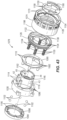
- a hammer drill comprising a drive mechanism including an electric motor and a transmission, a housing enclosing at least a portion of the drive mechanism, a spindle rotatable in response to receiving torque from the drive mechanism, a first ratchet coupled for co-rotation with the spindle, a second ratchet axially and rotationally fixed to the housing, the second ratchet defining a pocket on a side of the second ratchet that is opposite the first ratchet, a first bearing supporting a front portion of the spindle and radially positioned between the housing and the spindle, and a second bearing supporting a rear portion of the spindle and at least partially positioned in the pocket.
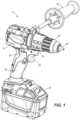
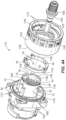
- a rotary power tool in this embodiment a hammer drill 10, includes a housing 12, a drive mechanism 14 and a spindle 18 rotatable in response to receiving torque from the drive mechanism 14.
- the drive mechanism 14 includes an electric motor 22 and a multi-speed transmission 26 between the motor 22 and the spindle 18.
- the drive mechanism 14 is at least partially enclosed by a transmission housing 30.
- a chuck 34 is provided at the front end of the spindle 18 so as to be co-rotatable with the spindle 18.
- the chuck 34 includes a plurality of jaws 38 configured to secure a tool bit or a drill bit (not shown), such that when the drive mechanism 14 is operated, the bit can perform a rotary and/or percussive action on a fastener or workpiece.
- the hammer drill 10 includes a pistol grip handle 36, a trigger 39 for activating the motor 22, and an auxiliary handle 40 that can be selectively removed from the transmission housing 30.
- the hammer drill 10 may be powered by an on-board power source such as a battery 41 or a remote power source (e.g., an alternating current source) via a cord (not shown).
- the hammer drill 10 includes a first ratchet 42 coupled for co-rotation with the spindle 18 and a second ratchet 46 axially and rotationally fixed to the transmission housing 30.
- the second ratchet 46 is rotationally fixed to the transmission housing 30 but allowed to translate axially with respect to the transmission housing 30.
- a first bearing 50 with an edge 54 is radially positioned between the transmission housing 30 and the spindle 18 and supports a front portion 58 of the spindle 18.
- the edge 54 is concave, but in other embodiments, the edge 54 may be chamfered or a combination of chamfered and concave.
- the front portion of the spindle 58 includes a radially outward-extending shoulder 60 adjacent to and axially in front of the bearing 50, such that the spindle 18 is not capable of translating axially rearward unless the bearing 50 also translates axially rearward.
- the bearing 50 is omitted and the edge 54 is located on the spindle 18.
- the second ratchet 46 includes a bearing pocket 62 defined in a rear end of the second ratchet 46.
- a second bearing 66 is at least partially positioned in the bearing pocket 62 and supports a rear portion 70 of the spindle 18.
- the second bearing 66 is wholly received in the bearing pocket 62, but in other embodiments the second bearing 66 may at least partially extend from the bearing pocket 62.
- the second bearing 66 is arranged about the rear portion 70 of the spindle 18 in a nested relationship within the second ratchet 46, thereby reducing the overall length of the hammer drill 10 while also supporting rotation of the spindle 18.
- the second ratchet 46 does not include a bearing pocket and the second bearing 66 is press-fit to the transmission housing 30.
- the hammer drill 10 includes a collar 74 that is rotatably adjustable by an operator of the hammer drill 10 to shift between "hammer drill,” “drill-only,” and “screwdriver” modes of operation, and to select a particular clutch setting when in “screwdriver mode.”
- the collar 74 is conveniently provided as a single collar that can be rotated to select different operating modes of the hammer drill 10 and different clutch settings. As shown in FIGS.
- the hammer drill 10 also includes an electronic clutch 78 capable of limiting the amount of torque that is transferred from the spindle 18 to a fastener (i.e., when in "screwdriver mode") by deactivating the motor 22 in response to a detected torque threshold or limit.
- the torque threshold is based on a detected current that is mapped to or indicative of an output torque of the motor.
- the electronic clutch 78 includes a printed circuit board (“PCB") 82 coupled to the transmission housing 30 and a wiper (not shown), which is coupled for co-rotation with the collar 74.
- the PCB 82 includes a plurality of electrical pads 86 which correspond to different clutch settings of the hammer drill 10. In other embodiments, instead of a wiper moving against pads 86, one or more of a potentiometer, hall sensor, or inductive sensor could be used for selecting the different clutch settings or mode settings.
- the hammer drill 10 also includes a hammer lockout mechanism 90 ( FIGS. 4-7 ) for selectively inhibiting the first and second ratchets 42, 46 from engaging when the hammer drill 10 is in a "screwdriver mode" or a "drill-only mode.”
- the hammer lockout mechanism 90 includes a selector ring 94 coupled for co-rotation with and positioned inside the collar 74, and a plurality of balls 98 situated within corresponding radial apertures A1, A2, A3, A4, and A5 asymmetrically positioned around an annular portion 102 of the transmission housing 30. As shown in FIGS.
- the selector ring 94 includes a plurality of recesses R1, R2, R3, R4, and R5 asymmetrically positioned about an inner periphery 104 of the selector ring 94.
- the number of recesses R1-R5 corresponds to the number of apertures A1-A5 and the number of balls 98 within the respective apertures A1-A5.
- the hammer lockout mechanism 90 could employ more or fewer apertures, balls, and recesses.
- the five apertures A1-A5 are approximately located at 0 degrees, 55 degrees, 145 degrees, 221 degrees, and 305 degrees, respectively, measured in a counterclockwise direction from an oblique plane 105 containing a longitudinal axis 108 of the hammer drill 10 and bisecting aperture A1. As shown in FIGS.
- the first ratchet 42 and the first bearing 50 are set within a cylindrical cavity 106 defined within the annular portion 102 of the transmission housing 30, and the selector ring 94 is radially arranged between the annular portion 102 and the collar 74, surrounding the apertures A1-A5.
- the axial force experienced by the tool bit is applied through the spindle 18 in a rearward direction, causing the spindle 18 to move axially rearward, thus forcing the first bearing 50 to move rearward and the edge 54 of the first bearing 50 to displace each of the balls 98 situated in the respective apertures A1-A5 radially outward to a "unlocking position", in which the balls 98 are partially received into the recesses R1-R5, thereby disabling the hammer lockout mechanism 90.
- the first ratchet 42 is permitted to engage with the second ratchet 46 to impart reciprocation to the spindle 18 as it rotates.
- the edge 54 of the first bearing 50 presses against the balls 98, which in turn abut against the inner periphery 104 of the selector ring 94 and are inhibited from displacing radially outward.
- the balls 98 remain in "locking positions" and each ball 98 is prevented from moving from the locking position to the unlocking position.
- the spindle 18 is blocked by the balls 98 in their locking positions, via the first bearing 50, and therefore the spindle 18 is prevented from moving rearward, maintaining a gap 110 between the first and second ratchets 42, 46.
- the hammer lockout mechanism 90 is enabled, preventing the spindle 18 from reciprocating in an axial manner as it is rotated by the drive mechanism 14, operating the hammer drill 10 in a "drill only" mode.
- the electronic clutch 78 adjusts which clutch setting to apply to the motor 22.
- the electronic clutch 78 operates the motor 22 to output torque at a predetermined maximum value to the spindle 18.
- the predetermined maximum value of torque output by the motor 22 may coincide with the maximum rated torque of the motor 22.
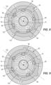
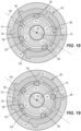
- the "hammer drill" position of the collar 74 corresponds to a "0 degree” or "first rotational position” position of the collar 74, in which the recesses R1, R2, R3, R4, R5 of the selector ring 94 are respectively and approximately located at 0, 55, 145, 221, and 305 degrees counterclockwise from the plane 105, such that the apertures A1, A2, A3, A4, A5 are thereby aligned.
- the recesses R1, R2, R3, R4, R5 are respectively and approximately located at 18 degrees, 73 degrees, 163 degrees, 239 degrees, and 323 degrees counterclockwise from the plane 105.
- the operator may continue to cycle through eighteen additional rotational positions of the collar 74, each corresponding to a different clutch setting in "screwdriver mode", by incrementally rotating the collar 74 counterclockwise by 18 degrees each time.
- the first clutch setting ( FIG. 8 ) provides a torque limit that is slightly less than the predetermined maximum value of torque output by the motor 22 available in the "hammer drill” mode or the "drill only” mode.
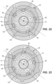
- the torque threshold applied to the motor 22 decreases, with the eighteenth clutch setting (shown in FIG. 25 ) providing the lowest torque limit to the motor 22.
- the "hammer drill" position in FIG. 5 is the only position in which all five apertures A1-A5 are aligned with all five recesses R1-R5, thereby disabling the hammer lockout mechanism 90 as described above.
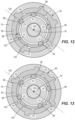
- the collar 74 and selector ring 94 no more than two of any of the apertures A1-A5 are aligned with the recesses R1-R5. Therefore, in "drill-only” mode ( FIG. 7 ) and “screwdriver mode” ( FIGS. 8-25 , clutch settings 1-18), at least three balls 98 inhibit the rearward movement of the spindle 18, via the first bearing 50, thereby enabling the hammer lockout mechanism 90 and preventing axial reciprocation of the spindle 18 as it rotates.
- FIG No. Aperture is aligned with which recess? 0 R1 R2 R3 R4 R5 5 Hammer Drill Max Torque 5 18 - - - - - 0 Drill Only Max Torque 7 36 - - - - - 0 Screwdriver 1 8 54 R5 R1 - - - 2 Screwdriver 2 9 72 - - - R3 R4 2 Screwdriver 3 10 90 - - R2 - R4 2 Screwdriver 4 11 108 - R5 - - - 1 Screwdriver 5 12 126 - - - - 0 Screwdriver 6 13 144 R4 - R1 - - 2 Screwdriver 7 14 162 - - - R2 R3 2 Screwdriver 8 15 180 - - - - - 0 Screwdriver 9 16 198 - R4 R5 -
- the collar 74 may be rotated a full 360 degrees and beyond in a single rotational direction, clockwise or counterclockwise, without any stops which would otherwise limit the extent to which the collar 74 may be rotated. Therefore, if the operator is using the hammer drill 10 in "screwdriver mode" on the eighteenth clutch setting ( FIG. 25 ), the operator needs only to rotate the collar 74 counterclockwise by an additional 18 degrees to switch the hammer drill 10 into “hammer drill” mode, rather than rotating the collar 74 in an opposite (clockwise) direction back through clutch settings 17 to 1 and "drill only” mode.
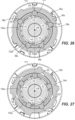
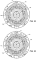
- FIGS. 26-41 A different embodiment of a hammer lockout mechanism 90a is shown in FIGS. 26-41 .
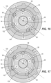
- the five apertures A1-A5 are approximately located at 0 degrees, 72 degrees, 156 degrees, 203 degrees, and 300 degrees, respectively, measured in a clockwise direction from a vertical plane 112 containing the longitudinal axis 108 of the hammer drill 10 and bisecting aperture A1.
- the axial force experienced by the tool bit is applied through the spindle 18 in a rearward direction, causing the spindle 18 to move axially rearward, thus forcing the first bearing 50 to move rearward and the edge 54 of the first bearing 50 to displace each of the balls 98a situated in the respective apertures A1-A5 radially outward to a "unlocking position", in which the balls 98a are partially received into the recesses R1-R5, thereby disabling the hammer lockout mechanism 90a.
- the first ratchet 42 is permitted to engage with the second ratchet 46 to impart reciprocation to the spindle 18 as it rotates.
- the edge 54 of the first bearing 50 presses against the balls 98a, which in turn abut against the inner periphery 104a of the selector ring 94a and are inhibited from displacing radially outward.
- the balls 98 remain in "locking positions" and each ball 98 is prevented from moving from the locking position to the unlocking position.
- the spindle 18 is blocked by the balls 98a in their locking positions, via the first bearing 50, and therefore the spindle 18 is prevented from moving rearward, maintaining a gap 110 between the first and second ratchets 42, 46.
- the hammer lockout mechanism 90a is enabled, preventing the spindle 18 from reciprocating in an axial manner as it is rotated by the drive mechanism 14, operating the hammer drill 10 in a "drill only" mode.
- the hammer lockout mechanism 90a is enabled, preventing the spindle 18 from reciprocating in an axial manner as it is rotated by the drive mechanism 14, operating that hammer drill 10 in a "screwdriver mode" with the first clutch setting.
- hammer lockout mechanism 90a there are a total of sixteen different positions between which the collar 74a and selector ring 94a can rotate.
- the collar 74a rotates 36 degrees counterclockwise from the first position ( FIG. 26 ) to the second position ( FIG. 27 ), and 36 degrees counterclockwise from the second position ( FIG. 27 ) to the third position ( FIG. 28 ).
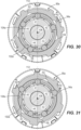
- the collar 74a is incrementally rotated 18 degrees each time to incrementally switch to the fourth and through the sixteenth positions.
- the wiper is in electrical and sliding contact with the PCB 82 as the collar 74a is rotated between each of the sixteen positions.
- the electronic clutch 78 adjusts which clutch setting to apply to the motor 22.
- the electronic clutch 78 operates the motor 22 to output torque at a predetermined maximum value to the spindle 18.
- the predetermined maximum value of torque output by the motor 22 may coincide with the maximum rated torque of the motor 22.
- the "hammer drill” position of the collar 74a corresponds to a "0 degree” or “first rotational position” position of the collar 74a, in which the recesses R1, R2, R3, R4, R5 of the selector ring 94a are respectively and approximately located at 0, 72, 156, 203 and 300 degrees clockwise from the plane 112, such that the apertures A1, A2, A3, A4, A5 are thereby aligned.
- the collar 74a is rotated 36 degrees counterclockwise from the "hammer drill” position to the "drill only” or “second rotational position” as shown in FIG.
- the recesses R1, R2, R3, R4, R5 are respectively and approximately located at 324 degrees, 36 degrees, 120 degrees, 167 degrees, and 264 degrees clockwise from the plane 112.
- the recesses R1, R2, R3, R4, R5 are respectively and approximately located at 288 degrees, 0 degrees, 84 degrees, 131 degrees, and 228 degrees clockwise from the plane 112.
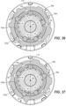
- the operator may continue to cycle through thirteen additional rotational positions of the collar 74a, each corresponding to a different clutch setting in "screwdriver mode", by incrementally rotating the collar 74a counterclockwise by 18 degrees each time.
- the first clutch setting ( FIG. 28 ) provides a torque limit that is slightly less than the predetermined maximum value of torque output by the motor 22 available in the "hammer drill” mode or the "drill only” mode.
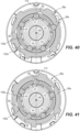
- the torque threshold applied to the motor 22 decreases, with the fourteenth clutch setting (shown in FIG. 41 ) providing the lowest torque limit to the motor 22.
- the fourteenth clutch setting shown in FIG. 41
- the collar 74a of hammer lockout mechanism 90a cannot be rotated a full 360 degrees and beyond in a single rotational direction, clockwise or counterclockwise, without any stops which would otherwise limit the extent to which the collar 74a may be rotated. Rather, after reaching the fourteenth clutch setting shown in FIG. 41 , the collar 74a may only be rotated back in a clockwise direction as viewed in FIGS. 26-41 , cycling chronologically downward through clutch settings thirteen through one in "screwdriver mode" ( FIGS. 42-28 ), then “drill only” ( FIG. 27 ), then "hammer drill” ( FIG. 26 ).
- the "hammer drill" position in FIG. 26 is the only position in which all five apertures A1-A5 are aligned with all five recesses R1-R5, thereby disabling the hammer lockout mechanism 90a as described above.
- the collar 74a and selector ring 94a no more than two of the apertures A1-A5 are aligned with the recesses R1-R5. Therefore, in "drill-only” mode ( FIG. 27 ) and "screwdriver mode" ( FIGS.
- At least three balls 98a inhibit the rearward movement of the spindle 18, via the first bearing 50, thereby enabling the hammer lockout mechanism 90a and preventing axial reciprocation of the spindle 18 as it rotates.
- FIG No. Aperture is aligned with which recess? 0 R1 R2 R3 R4 R5 5 Hammer Drill Max Torque 26 36 - - R4 - - 1 Drill Only Max Torque 27 72 R2 - - - - 1 Screwdriver 1 28 90 - R3 - R5 - 2 Screwdriver 2 29 108 - - - R5 - 1 Screwdriver 3 30 126 - R4 - - R2 2 Screwdriver 4 31 144 - - R5 - - 1 Screwdriver 5 32 162 R3 - - R1 - 2 Screwdriver 6 33 180 - - - - - 0 Screwdriver 7 34 198 R4 - R1 - - 2 Screwdriver 8 35 216 - - - - R3 1 Screwdriver 9 36 234 - - - R2 -
- the hammer drill 1010 includes a drive mechanism 1014 and a spindle 1018 rotatable in response to receiving torque from the drive mechanism 1014.
- the drive mechanism 1014 includes an electric motor (not shown) and a multi-speed transmission 1026 between the motor and the spindle 1018.
- the drive mechanism 1014 is at least partially enclosed by a transmission housing 1030.
- a chuck 1034 is provided at the front end of the spindle 1018 so as to be co-rotatable with the spindle 1018.
- the chuck 1034 includes a plurality of jaws 1038 configured to secure a tool bit or a drill bit (not shown), such that when the drive mechanism 1014 is operated, the bit can perform a rotary and/or percussive action on a fastener or workpiece.
- the hammer drill 1010 may be powered by an on-board power source (e.g., a battery, not shown) or a remote power source (e.g., an alternating current source) via a cord (also not shown).
- the hammer drill 1010 includes a first ratchet 1042 coupled for co-rotation with the spindle 1018 and a second ratchet 1046 axially and rotationally fixed to the transmission housing 1030.
- the second ratchet 1046 is rotationally fixed to the transmission housing 1030 but allowed to translate axially with respect to the transmission housing 1030.
- a first bearing 1050 with an edge 1054 is radially positioned between the transmission housing 1030 and the spindle 1018 and supports a front portion 1058 of the spindle 1018.
- the edge 1054 is concave, but in other embodiments, the edge 1054 may be chamfered or a combination of chamfered and concave.
- the front portion of the spindle 1058 includes a radially outward-extending shoulder 1060 adjacent to and axially in front of the bearing 1050, such that the spindle 1018 is not capable of translating axially rearwards unless the bearing 1050 also translates axially rearward.
- the bearing 1050 is omitted and the edge 1054 is located on the spindle 1018.
- the second ratchet 1046 includes a bearing pocket 1062 defined in a rear end of the second ratchet 1046.
- a second bearing 1066 is at least partially positioned in the bearing pocket 1062 and supports a rear portion 1070 of the spindle 1018.
- the second bearing 1066 is wholly received in the bearing pocket 1062, but in other embodiments the second bearing 1066 may at least partially extend from the bearing pocket 1062.
- the second bearing 1066 is arranged about the rear portion 1070 of the spindle 1018 in a nested relationship within the second ratchet 1046, thereby reducing the overall length of the hammer drill 1010 while also supporting rotation of the spindle 1018.
- the second ratchet 1046 does not include a bearing pocket and the second bearing 1066 is press-fit to the transmission housing 1030.
- the hammer drill 10 includes a collar 1074 that is rotatably adjustable by an operator of the hammer drill 1010 to shift between "hammer drill,” “drill-only,” and “screwdriver” modes of operation, and to select a particular clutch setting when in “screwdriver mode.”
- the collar 1074 is conveniently provided as a single collar 1074 that can be rotated to select different operating modes of the hammer drill 1010 and different clutch settings.
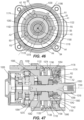
- the hammer drill 1010 includes a mechanical clutch mechanism 1078 capable of limiting the amount of torque that is transferred from the spindle 1018 to a fastener (i.e., when in "screwdriver mode").
- the clutch mechanism 1078 includes a plurality of cylindrical pins 1082 received within respective apertures 1086 in the transmission housing 1030, a clutch plate 1090, a clutch face 1098 defined on an outer ring gear 1094 of the transmission 1026, and a plurality of followers, such as balls 1102, positioned between the respective pins 1082 and the clutch face 1098.
- the outer ring gear 1094 is positioned in the transmission housing 1030 of the drill and is part of the third planetary stage of the transmission 1026.
- the clutch face 1098 includes a plurality of ramps 1106 over which the balls 1102 ride when the clutch mechanism 1078 is engaged.
- the ramps 1106 extend an axial distance D1 from the clutch face 1098, such that the balls 1102 must be able to axially translate at least a distance of D1 away from clutch face 1098 in order to ride over the ramps 1106 and thereby clutch the hammer drill 1010.
- the clutch plate 1090 includes a plurality of first keyways 1110 that are received onto respective keys 1114, which extend radially outward from and axially along an annular portion 1118 of the transmission housing 1030. As such, the clutch plate 1090 is axially movable along the annular portion 1118, but is prevented from rotating with respect to the annular portion 1118.
- the clutch mechanism 1078 further includes a retainer 1122 with a first (outer) threaded portion 1126.
- the first threaded portion 1126 threadably engages a second (inner) threaded portion 1128 on the collar 1074.
- the clutch mechanism 1078 also includes plurality of biasing members, such as compression springs 1130, that are received in respective seats 1134 on the retainer 1122.
- the compression springs 1130 are biased between the retainer 1122 and the clutch plate 1090.
- a second axial distance D2 coinciding with a gap between the clutch plate 1090 and the retainer 1122, when the hammer drill 1010 is not in operation, is shown in FIG. 42 .
- the second axial distance D2 is adjustable by rotation of the collar 1074 and corresponding axial adjustment of the retainer 1122.
- the retainer 1122 includes a plurality of second keyways 1138 that are also received onto the respective keyways 1114.
- the retainer 1122 is prevented from rotating with respect to the annular portion 1118 but is allowed to slide axially along the annular portion 1118 as the clutch mechanism 1078 is adjusted by the collar 1074, as will be described in further detail below.
- other embodiments may include more than six or fewer than six pins, apertures, balls, ramps and springs.
- a retaining clip 1142 is locked within a circumferential groove 1146 in the annular portion 1118.
- the retaining clip 1142 prevents forward axial displacement of a detent ring 1150, which is arranged between a forward portion 1154 of the collar 1074 and the retaining clip 1142.
- the detent ring 1150 has a plurality of protrusions 1158 that extend radially inward and are designed to fit within gaps 1162 on the annular portion 1118 of the transmission housing, thereby rotationally locking the detent ring 1150 with respect to the annular portion 1118.
- the detent ring 1150 also has an axially rearward-extending detent portion 1166 that is configured to selectively engage a plurality of valleys 1170 on the forward portion 1154 of the collar 1074, as will be explained in further detail below.
- the hammer drill 1010 also includes a hammer lockout mechanism 1174 for selectively inhibiting the first and second ratchets 1042, 1046 from engaging when the hammer drill 1010 is in a "screwdriver mode" or a "drill-only mode.”
- the hammer lockout mechanism 1174 includes a lockout ring 1178 coupled for co-rotation with and positioned inside the collar 1074, and a plurality of detents, such as balls B1, B2, B3, B4 and B5 situated within corresponding radial apertures A1, A2, A3, A4, and A5 asymmetrically positioned around the annular portion 1118 of the transmission housing 1030. As shown in FIGS.
- the lockout ring 1138 includes a plurality of recesses R1, R2, R3, R4, and R5 asymmetrically positioned about an inner surface 1182 of the lockout ring 1178.
- the number of recesses R1-R5 corresponds to the number of apertures A1-A5 and the number of balls B1-B5 within the respective apertures A1-A5.
- five apertures A1-A5 containing five balls B1-B5 are located in the annular portion 1118 of the transmission housing 1030 and five recesses R1-R5 are defined in the lockout ring 1178.
- the hammer lockout mechanism 1174 could employ more or fewer apertures, balls, and recesses.
- the five apertures A1-A5 are approximately located at 0 degrees, 55 degrees, 145 degrees, 221 degrees, and 305 degrees, respectively, measured in a counterclockwise direction from an oblique plane 1186 containing a longitudinal axis 1190 of the hammer drill 1010 and bisecting aperture A1.
- the first ratchet 1042 and the first bearing 1050 are set within a cylindrical cavity 1194 defined within the annular portion 1118 of the transmission housing 1030, and the lockout ring 1178 is radially arranged between the annular portion 1118 and the collar 1074, surrounding the apertures A1-A5.
- a lockout spring 1196 is also arranged within the cavity 1194 between the second ratchet 1046 and the first bearing 1050. The lockout spring 1196 biases the first bearing 1050 away from the second ratchet 1046. As shown in FIG.
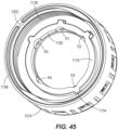
- a rear rim 1198 of the collar 1074 includes a first stop 1202 that extends radially inward.
- the first stop 1202 is configured to abut against a second stop 1206 on the transmission housing 1030, as shown in FIG. 50 and as will be explained in further detail below.
- the axial force experienced by the tool bit is applied through the spindle 1018 in a rearward direction, causing the spindle 1018 to move axially rearward, thus forcing the first bearing 1050 to move rearward and the edge 1054 of the first bearing 1050 to displace each of the balls B1-B5 situated in the respective apertures A1-A5 radially outward to a "unlocking position", in which the balls B1-B5 are respectively partially received into the recesses R1-R5, thereby disabling the hammer lockout mechanism 1174.
- the first ratchet 1042 is permitted to engage with the second ratchet 1046 to impart reciprocation to the spindle 1018 as it rotates.
- the edge 1054 of the first bearing 1050 presses against the balls B1-B5, which in turn abut against the inner surface 1182 of the lockout ring 1178 and are inhibited from displacing radially outward.
- the balls B1-B5 remain in "locking positions" and each ball is prevented from moving from the locking position to the unlocking position.
- the spindle 1018 is blocked by the balls B1-B5 in their locking positions, via the first bearing 1050, and therefore the spindle 1018 is prevented from moving rearward, maintaining a gap 1210 between the first and second ratchets 1042, 1046.
- the hammer lockout mechanism 1174 is enabled, preventing the spindle 1018 from reciprocating in an axial manner as it is rotated by the drive mechanism 1014, operating the hammer drill 1010 in a "drill only" mode.
- the retainer 1122 axially adjusts along the annular portion 1118 via the threaded engagement between the first threaded portion 1126 of the retainer 1122 and the second threaded portion 1128 of the collar 1074.
- the axial adjustment of the retainer 1122 adjusts the pre-load on the springs 1130, thereby increasing or decreasing the torque limit of the clutch mechanism 1078.
- the second axial distance D2 is increased, and as the retainer 1122 is adjusted axially towards the clutch plate 1090, the second axial distance D2 is decreased.
- the detent portion 1166 engages one of the valleys 1170 on the forward portion 1154 of the collar 1074, thereby temporarily locking the collar 1074 in the respective rotational position.
- the "hammer drill” position of the collar 1074 corresponds to a "0 degree” or "first rotational position” position of the collar 1074, in which the recesses R1, R2, R3, R4, R5 of the lockout ring 1178 are respectively and approximately located at 0, 55, 145, 221, and 305 degrees counterclockwise from the plane 1186, such that the apertures A1, A2, A3, A4, A5 are thereby aligned.
- the recesses R1, R2, R3, R4, R5 are respectively and approximately located at 18 degrees, 73 degrees, 163 degrees, 239 degrees, and 323 degrees counterclockwise from the plane 1186.
- the retainer 1122 is adjusted to a first axial position with respect to the transmission housing 1030.
- the first axial position of the retainer 1122 corresponds to a minimum value of the second axial distance D2, in which D2 is less than the first axial distance D1.
- the clutch plate 1090 is capable of being axially translated by balls 1102 and pins 1082 towards the retainer 1122 by a maximum axial distance of D2.
- balls 1102 are capable of axially translating a maximum distance of D2 away from clutch face 1098, but because D2 is less than D1, the balls 1102 are prevented from riding over ramps 1106, which have an axial length of D1.
- the clutch mechanism 1078 is locked out and the motor is permitted to output torque at a maximum value to the spindle 1018.
- the maximum value of torque output by the motor may coincide with the maximum rated torque of the motor.
- the retainer 1122 is axially adjusted to a second axial position that is a slight axial distance away from the first axial position and the transmission housing 1030, such that there is a slight increase in the second axial distance D2 and thus a slight decrease in the preload on the springs 1130.
- the second axial distance D2 is still less than the first axial distance D1.
- the clutch mechanism 1078 is still locked-out in "drill only” mode, allowing the motor to output torque at a maximum value to the spindle 1018.
- the operator may continue to cycle through eighteen additional rotational positions of the collar 1074, each corresponding to a different clutch setting in "screwdriver mode", by incrementally rotating the collar 1074 counterclockwise by 18 degrees each time.
- the retainer 1122 moves progressively axially farther away from the first axial position, causing the pre-load on the springs 1130, and thus the torque limit of the clutch mechanism 1078, to progressively decrease, with the eighteenth clutch setting providing the lowest torque limit to the motor.
- the retainer 1122 is axially far enough away from the first axial position that the second axial distance D2 is greater than the first axial distance D1.
- the clutch mechanism 1078 reduces the torque output of the spindle 1018, as described below.
- torque is transferred from the electric motor, through the transmission 1026, and to the spindle 1018, during which time the outer ring gear 1094 remains stationary with respect to the transmission housing 1030 due to the pre-load exerted on the clutch face 1098 by the springs 1130, the clutch plate 1090, the pins 1082 and the balls 1102.
- a corresponding reaction torque is imparted to the spindle 1018, causing the rotational speed of the spindle 1018 to decrease.
- the "hammer drill" position in FIG. 46 is the only position in which all five apertures A1-A5 are aligned with all five recesses R1-R5, thereby disabling the hammer lockout mechanism 1090 as described above.
- the collar 1074 and lockout ring 1178 no more than two of any of the apertures A1-A5 are aligned with the recesses R1-R5. Therefore, in "drill-only" mode ( FIG.
- FIG No. Aperture is aligned with which recess? 0 R1 R2 R3 R4 R5 5 Hammer Drill Max Torque 46 18 - - - - - 0 Drill Only Max Torque 48 36 - - - - - 0 Screwdriver 1 N/A 54 R5 R1 - - - 2 Screwdriver 2 N/A 72 - - - R3 R4 2 Screwdriver 3 N/A 90 - - R2 - R4 2 Screwdriver 4 N/A 108 - R5 - - - 1 Screwdriver 5 N/A 126 - - - - 0 Screwdriver 6 N/A 144 R4 - R1 - - 2 Screwdriver 7 N/A 162 - - - R2 R3 2 Screwdriver 8 N/A 180 - - - - - 0
- the hammer drill 1010 is adjustable between "hammer drill” mode, "drill only” mode and the eighteen clutch settings of "screwdriver” mode by rotating the collar 342 degrees, but the collar is prevented from rotating a full 360 degrees because the first stop 1202 of the collar ( FIG. 45 ) physically abuts the second stop 1206 on the transmission housing 1030 ( FIG. 50 ).
- the first and second stops 1202, 1206 are omitted, and the collar 1074 may be rotated a full 360 degrees and beyond in a single rotational direction, clockwise or counterclockwise, without any stops which would otherwise limit the extent to which the collar 1074 may be rotated. Therefore, if the operator is using the hammer drill 1010 in "screwdriver mode" on the eighteenth clutch setting, the operator needs only to rotate the collar 1074 counterclockwise by an additional 18 degrees to switch the hammer drill 1010 into "hammer drill” mode, rather than rotating the collar 1074 in an opposite (clockwise) direction back through clutch settings 17 to 1 and "drill only” mode.
Landscapes
- Engineering & Computer Science (AREA)
- Mechanical Engineering (AREA)
- Percussive Tools And Related Accessories (AREA)
- Drilling And Boring (AREA)
Applications Claiming Priority (4)
| Application Number | Priority Date | Filing Date | Title |
|---|---|---|---|
| US201762501962P | 2017-05-05 | 2017-05-05 | |
| US201762531054P | 2017-07-11 | 2017-07-11 | |
| PCT/US2018/031017 WO2018204741A1 (en) | 2017-05-05 | 2018-05-04 | Power tool |
| EP18794567.0A EP3606702B1 (de) | 2017-05-05 | 2018-05-04 | Bohrhammer |
Related Parent Applications (2)
| Application Number | Title | Priority Date | Filing Date |
|---|---|---|---|
| EP18794567.0A Division EP3606702B1 (de) | 2017-05-05 | 2018-05-04 | Bohrhammer |
| EP18794567.0A Division-Into EP3606702B1 (de) | 2017-05-05 | 2018-05-04 | Bohrhammer |
Publications (2)
| Publication Number | Publication Date |
|---|---|
| EP4497546A2 true EP4497546A2 (de) | 2025-01-29 |
| EP4497546A3 EP4497546A3 (de) | 2025-04-23 |
Family
ID=64013566
Family Applications (2)
| Application Number | Title | Priority Date | Filing Date |
|---|---|---|---|
| EP24218470.3A Pending EP4497546A3 (de) | 2017-05-05 | 2018-05-04 | Bohrhammer |
| EP18794567.0A Active EP3606702B1 (de) | 2017-05-05 | 2018-05-04 | Bohrhammer |
Family Applications After (1)
| Application Number | Title | Priority Date | Filing Date |
|---|---|---|---|
| EP18794567.0A Active EP3606702B1 (de) | 2017-05-05 | 2018-05-04 | Bohrhammer |
Country Status (4)
| Country | Link |
|---|---|
| US (5) | US10737373B2 (de) |
| EP (2) | EP4497546A3 (de) |
| CN (1) | CN210081641U (de) |
| WO (1) | WO2018204741A1 (de) |
Families Citing this family (11)
| Publication number | Priority date | Publication date | Assignee | Title |
|---|---|---|---|---|
| KR102074052B1 (ko) * | 2015-06-02 | 2020-02-05 | 밀워키 일렉트릭 툴 코포레이션 | 전자 클러치를 갖는 다중-속도 전동 공구 |
| WO2018204741A1 (en) * | 2017-05-05 | 2018-11-08 | Milwaukee Electric Tool Corporation | Power tool |
| US11148273B2 (en) * | 2018-03-30 | 2021-10-19 | Milwaukee Electric Tool Corporation | Rotary power tool including transmission housing bushing |
| EP3808478B1 (de) | 2019-10-14 | 2022-04-06 | Nanjing Chervon Industry Co., Ltd. | Schlagbohrer |
| US20210331300A1 (en) * | 2020-04-28 | 2021-10-28 | Snap-On Incorporated | Quick change indexable ratchet head |
| US11964376B2 (en) * | 2020-09-24 | 2024-04-23 | Techtronic Cordless Gp | Multi-function handheld electric tool |
| US12048988B2 (en) | 2020-12-08 | 2024-07-30 | Snap-On Incorporated | Impact mechanism for a rotary impact tool |
| WO2023009625A1 (en) * | 2021-07-28 | 2023-02-02 | Milwaukee Electric Tool Corporation | Clutch assembly for a power tool |
| US12030168B2 (en) | 2021-08-18 | 2024-07-09 | Milwaukee Electric Tool Corporation | Clutch assembly for a power tool |
| US12434371B2 (en) | 2022-03-23 | 2025-10-07 | Milwaukee Electric Tool Corporation | Electronic clutch for power tools |
| US12122028B2 (en) | 2022-05-26 | 2024-10-22 | Milwaukee Electric Tool Corporation | Electronic clutch for powered fastener driver |
Family Cites Families (48)
| Publication number | Priority date | Publication date | Assignee | Title |
|---|---|---|---|---|
| DE1031611B (de) * | 1954-06-18 | 1958-06-04 | Willy Suhner | Einrichtung zum Feststellen der an ihrem freien Ende eine das Werk-zeug aufnehmende Spannzange tragenden Antriebsspindel bei von Hand gefuehrten Vorrichtungen zum Feilen, Schleifen od. dgl. |
| US3020789A (en) | 1960-04-11 | 1962-02-13 | Skil Corp | Predetermined torque release hand tool |
| US3187865A (en) | 1962-12-21 | 1965-06-08 | Skil Corp | Predetermined torque release tool with non-ratcheting feature |
| US3511321A (en) * | 1968-09-04 | 1970-05-12 | Milwaukee Electric Tool Corp | Hammer drill |
| US3834252A (en) | 1973-06-11 | 1974-09-10 | Black & Decker Mfg Co | Adjustable positive clutch screwdriver |
| US4273344A (en) * | 1978-08-08 | 1981-06-16 | The Boeing Company | Motor quick-change chuck system for tool having cylindrically shaped adapter portion |
| DE4038502C2 (de) | 1990-12-03 | 1994-02-17 | Atlas Copco Elektrowerkzeuge | Handgeführte Elektrowerkzeugmaschine mit einer Einrichtung zum Einstellen des Drehmoments |
| DE4123349C1 (de) | 1991-07-15 | 1993-03-04 | Fein C & E | Schrauber mit variabler Drehmomenteinstellung |
| GB9304540D0 (en) * | 1993-03-05 | 1993-04-21 | Black & Decker Inc | Power tool and mechanism |
| GB9309054D0 (en) | 1993-05-01 | 1993-06-16 | Black & Decker Inc | Power tools and hammer mechanisms therefor |
| US5451127A (en) | 1994-04-12 | 1995-09-19 | Chung; Lee-Hsin-Chih | Dual-function electrical hand drill |
| US5738177A (en) | 1995-07-28 | 1998-04-14 | Black & Decker Inc. | Production assembly tool |
| EP1157791B1 (de) | 1995-07-28 | 2007-01-17 | Black & Decker Inc. | Montagewerkzeug |
| EP1681138B1 (de) | 1995-07-28 | 2008-09-10 | Black & Decker, Inc. | Montagewerkzeug |
| JP4237871B2 (ja) | 1999-05-27 | 2009-03-11 | 京セラ株式会社 | 光ファイバカップラとその製造方法及びこれを用いた光増幅器 |
| US6213222B1 (en) * | 2000-01-06 | 2001-04-10 | Milwaukee Electric Tool Corporation | Cam drive mechanism |
| US6676557B2 (en) | 2001-01-23 | 2004-01-13 | Black & Decker Inc. | First stage clutch |
| US6502648B2 (en) | 2001-01-23 | 2003-01-07 | Black & Decker Inc. | 360 degree clutch collar |
| US7101300B2 (en) | 2001-01-23 | 2006-09-05 | Black & Decker Inc. | Multispeed power tool transmission |
| WO2002058883A1 (en) | 2001-01-23 | 2002-08-01 | Black & Decker Inc. | 360 degree clutch collar |
| US6595300B2 (en) | 2001-12-20 | 2003-07-22 | Black & Decker Inc. | Side handles on drill/drivers |
| DE10205030A1 (de) | 2002-02-07 | 2003-08-21 | Hilti Ag | Betriebsmodi-Schalteinheit einer Handwerkzeugmaschine |
| GB0213289D0 (en) | 2002-06-11 | 2002-07-24 | Black & Decker Inc | Rotary hammer |
| DE20305853U1 (de) * | 2003-04-11 | 2003-09-04 | Mobiletron Electronics Co., Ltd., Taya, Taichung | Elektrowerkzeug mit einem Funktionssteuerungsmechanismus zur Steuerung der Bedienung in einem Dreh- oder einem Hammermodus |
| DE102004051911A1 (de) | 2004-10-26 | 2006-04-27 | Robert Bosch Gmbh | Handwerkzeugmaschine, insbesondere Bohrschrauber |
| US7314097B2 (en) | 2005-02-24 | 2008-01-01 | Black & Decker Inc. | Hammer drill with a mode changeover mechanism |
| US7469753B2 (en) | 2005-06-01 | 2008-12-30 | Milwaukee Electric Tool Corporation | Power tool, drive assembly, and method of operating the same |
| DE102005048345A1 (de) * | 2005-10-10 | 2007-04-12 | Robert Bosch Gmbh | Handwerkzeugmaschinenzusatzeinheit |
| US7980324B2 (en) | 2006-02-03 | 2011-07-19 | Black & Decker Inc. | Housing and gearbox for drill or driver |
| DE602006001740D1 (de) * | 2006-05-19 | 2008-08-21 | Black & Decker Inc | Betriebsartumschaltvorrichtung für ein kraftbetriebenes Werkzeug |
| DE102006056853A1 (de) | 2006-12-01 | 2008-06-05 | Robert Bosch Gmbh | Handwerkzeugmaschine |
| US7798245B2 (en) | 2007-11-21 | 2010-09-21 | Black & Decker Inc. | Multi-mode drill with an electronic switching arrangement |
| US7762349B2 (en) | 2007-11-21 | 2010-07-27 | Black & Decker Inc. | Multi-speed drill and transmission with low gear only clutch |
| US7717192B2 (en) | 2007-11-21 | 2010-05-18 | Black & Decker Inc. | Multi-mode drill with mode collar |
| US7717191B2 (en) | 2007-11-21 | 2010-05-18 | Black & Decker Inc. | Multi-mode hammer drill with shift lock |
| US7854274B2 (en) | 2007-11-21 | 2010-12-21 | Black & Decker Inc. | Multi-mode drill and transmission sub-assembly including a gear case cover supporting biasing |
| CN201220406Y (zh) | 2008-02-03 | 2009-04-15 | 南京德朔实业有限公司 | 一种电动工具 |
| US9193053B2 (en) | 2008-09-25 | 2015-11-24 | Black & Decker Inc. | Hybrid impact tool |
| DE102010042682A1 (de) | 2010-10-20 | 2012-04-26 | Robert Bosch Gmbh | Bohrmaschine |
| US9289886B2 (en) | 2010-11-04 | 2016-03-22 | Milwaukee Electric Tool Corporation | Impact tool with adjustable clutch |
| EP2525467B1 (de) | 2011-05-19 | 2017-06-21 | Black & Decker Inc. | Elektronisches Schaltmodul für ein Elektrowerkzeug |
| DE102012005864A1 (de) | 2011-10-22 | 2013-04-25 | Wolfgang Schmid | Taumelwelle mit integrierter Sicherheitskupplung und Verriegelung |
| US9283667B2 (en) | 2012-01-11 | 2016-03-15 | Black & Decker Inc. | Power tool with torque clutch |
| US9193055B2 (en) | 2012-04-13 | 2015-11-24 | Black & Decker Inc. | Electronic clutch for power tool |
| WO2014062868A1 (en) | 2012-10-19 | 2014-04-24 | Milwaukee Electric Tool Corporation | Hammer drill |
| KR102074052B1 (ko) | 2015-06-02 | 2020-02-05 | 밀워키 일렉트릭 툴 코포레이션 | 전자 클러치를 갖는 다중-속도 전동 공구 |
| WO2018204741A1 (en) * | 2017-05-05 | 2018-11-08 | Milwaukee Electric Tool Corporation | Power tool |
| WO2020058883A1 (en) | 2018-09-19 | 2020-03-26 | Sendyne Corporation | Improved analog computing implementing amplitude rescaling for solving non-linear differential equations and methods of use |
-
2018
- 2018-05-04 WO PCT/US2018/031017 patent/WO2018204741A1/en not_active Ceased
- 2018-05-04 EP EP24218470.3A patent/EP4497546A3/de active Pending
- 2018-05-04 US US15/971,007 patent/US10737373B2/en active Active
- 2018-05-04 CN CN201890000224.4U patent/CN210081641U/zh active Active
- 2018-05-04 EP EP18794567.0A patent/EP3606702B1/de active Active
-
2020
- 2020-07-07 US US16/922,110 patent/US11583988B2/en active Active
-
2021
- 2021-09-22 US US17/482,041 patent/US11426852B2/en active Active
-
2022
- 2022-08-24 US US17/894,210 patent/US12083661B2/en active Active
-
2024
- 2024-08-26 US US18/815,168 patent/US20240416495A1/en active Pending
Also Published As
| Publication number | Publication date |
|---|---|
| US20220410359A1 (en) | 2022-12-29 |
| WO2018204741A1 (en) | 2018-11-08 |
| US11426852B2 (en) | 2022-08-30 |
| EP4497546A3 (de) | 2025-04-23 |
| EP3606702B1 (de) | 2025-02-12 |
| US20240416495A1 (en) | 2024-12-19 |
| US11583988B2 (en) | 2023-02-21 |
| US20220001522A1 (en) | 2022-01-06 |
| EP3606702A1 (de) | 2020-02-12 |
| EP3606702A4 (de) | 2021-03-10 |
| US20180318998A1 (en) | 2018-11-08 |
| US20200331136A1 (en) | 2020-10-22 |
| US10737373B2 (en) | 2020-08-11 |
| US12083661B2 (en) | 2024-09-10 |
| CN210081641U (zh) | 2020-02-18 |
Similar Documents
| Publication | Publication Date | Title |
|---|---|---|
| US11426852B2 (en) | Power tool | |
| US11440173B2 (en) | Rotary power tool including transmission housing bushing | |
| US11826892B2 (en) | Hammer drill | |
| EP2318636B1 (de) | Präzisionsdrehmomentschrauber | |
| EP1574294B1 (de) | Schlagantrieb | |
| US8322457B2 (en) | Power tool chuck assembly with hammer mechanism | |
| US10513023B2 (en) | Power tool | |
| CN105666427A (zh) | 具有转矩离合器的手持式工具机 | |
| DE2557118C2 (de) | Tragbare Drehschlag-Maschinen mit ausrastbarem Schlagwerk | |
| US11986940B2 (en) | Clutch assembly for a power tool |
Legal Events
| Date | Code | Title | Description |
|---|---|---|---|
| PUAI | Public reference made under article 153(3) epc to a published international application that has entered the european phase |
Free format text: ORIGINAL CODE: 0009012 |
|
| STAA | Information on the status of an ep patent application or granted ep patent |
Free format text: STATUS: THE APPLICATION HAS BEEN PUBLISHED |
|
| AC | Divisional application: reference to earlier application |
Ref document number: 3606702 Country of ref document: EP Kind code of ref document: P |
|
| AK | Designated contracting states |
Kind code of ref document: A2 Designated state(s): AL AT BE BG CH CY CZ DE DK EE ES FI FR GB GR HR HU IE IS IT LI LT LU LV MC MK MT NL NO PL PT RO RS SE SI SK SM TR |
|
| REG | Reference to a national code |
Ref country code: DE Ref legal event code: R079 Free format text: PREVIOUS MAIN CLASS: B25F0005000000 Ipc: B25D0016000000 |
|
| PUAL | Search report despatched |
Free format text: ORIGINAL CODE: 0009013 |
|
| RIN1 | Information on inventor provided before grant (corrected) |
Inventor name: DEDRICKSON, RYAN A. Inventor name: DUNCAN, IAN |
|
| AK | Designated contracting states |
Kind code of ref document: A3 Designated state(s): AL AT BE BG CH CY CZ DE DK EE ES FI FR GB GR HR HU IE IS IT LI LT LU LV MC MK MT NL NO PL PT RO RS SE SI SK SM TR |
|
| RIC1 | Information provided on ipc code assigned before grant |
Ipc: B25D 16/00 20060101AFI20250318BHEP |
|
| STAA | Information on the status of an ep patent application or granted ep patent |
Free format text: STATUS: REQUEST FOR EXAMINATION WAS MADE |
|
| 17P | Request for examination filed |
Effective date: 20251023 |