EP4497523A1 - Cutting insert and turning tool - Google Patents
Cutting insert and turning tool Download PDFInfo
- Publication number
- EP4497523A1 EP4497523A1 EP23774500.5A EP23774500A EP4497523A1 EP 4497523 A1 EP4497523 A1 EP 4497523A1 EP 23774500 A EP23774500 A EP 23774500A EP 4497523 A1 EP4497523 A1 EP 4497523A1
- Authority
- EP
- European Patent Office
- Prior art keywords
- cutting edge
- corner
- cutting insert
- cutting
- longitudinal direction
- Prior art date
- Legal status (The legal status is an assumption and is not a legal conclusion. Google has not performed a legal analysis and makes no representation as to the accuracy of the status listed.)
- Pending
Links
Images




Classifications
-
- B—PERFORMING OPERATIONS; TRANSPORTING
- B23—MACHINE TOOLS; METAL-WORKING NOT OTHERWISE PROVIDED FOR
- B23B—TURNING; BORING
- B23B27/00—Tools for turning or boring machines; Tools of a similar kind in general; Accessories therefor
- B23B27/04—Cutting-off tools
-
- B—PERFORMING OPERATIONS; TRANSPORTING
- B23—MACHINE TOOLS; METAL-WORKING NOT OTHERWISE PROVIDED FOR
- B23B—TURNING; BORING
- B23B2200/00—Details of cutting inserts
- B23B2200/20—Top or side views of the cutting edge
- B23B2200/201—Details of the nose radius and immediately surrounding area
-
- B—PERFORMING OPERATIONS; TRANSPORTING
- B23—MACHINE TOOLS; METAL-WORKING NOT OTHERWISE PROVIDED FOR
- B23B—TURNING; BORING
- B23B2200/00—Details of cutting inserts
- B23B2200/20—Top or side views of the cutting edge
- B23B2200/202—Top or side views of the cutting edge with curved cutting edge
-
- B—PERFORMING OPERATIONS; TRANSPORTING
- B23—MACHINE TOOLS; METAL-WORKING NOT OTHERWISE PROVIDED FOR
- B23B—TURNING; BORING
- B23B29/00—Holders for non-rotary cutting tools; Boring bars or boring heads; Accessories for tool holders
- B23B29/04—Tool holders for a single cutting tool
- B23B29/046—Tool holders for a single cutting tool with an intermediary toolholder
Definitions
- the present invention relates to a two-corner type cutting insert and a turning tool provided with the cutting insert.
- a dog-bone type cutting insert which has substantially a rod shape and has at both end portions thereof cutting edges (see, for example, Patent Documents 1 to 4). Since a cutting insert having such a shape can perform grooving and cutting off as well as lateral feed machining, the cutting insert can be used for finishing and copy machining of a product.
- a blisk in which blades and a rotor disk are integrated in order to reduce weight and improve performance, is used in a turbine for a turbo pump mounted in an engine system for an aircraft, a space rocket, or the like.
- a labyrinth seal is often used as a seal to suppress fluid from leaking from a gap between the blisk that rotates due to fluid pressure and a stator which is stationary. Fin-like protrusions that constitute the labyrinth seal are machined on the surface of the blisk.
- a gap between adjacent protrusions on the surface of the blisk is designed to be narrow such that the protrusions machined on the blisk and the protrusions machined on the stator are intricately intertwined to provide sealing performance.
- the cutting inserts described in Patent Documents 1 to 3 have at both end portions thereof circular or trapezoidal cutting edges. When an unmachined portion is machined with a cutting edge having such a shape, the cutting edge interferes with an adjacent machined portion, and thus it is not possible to machine a structure that includes a narrow gap.
- a form tool or insert that has a shape that replicates the gap between the protrusions of the labyrinth seal is used.
- the blisk which is used in harsh environments where the blisk is constantly exposed to high temperatures, is made of a difficult-to-cut material such as a nickel-based alloy or titanium alloy. Since a cutting resistance is higher in form tool machining than in copy machining or the like, when the difficult-to-cut material is machined, machining defects (chattering) may occur due to vibration, or the protrusions may bend during machining to escape from the cutting edge, resulting in reduced machining accuracy. Since the sealing performance of the labyrinth seal affects the efficiency of the turbo pump, particularly strict machining precision is required for the machining of the protrusions inside the seal.
- a cutting insert extends in a longitudinal direction from a first end to a second end on an opposite side to the first end.
- a first end portion that includes the first end and a portion in the vicinity thereof and a second end portion that includes the second end and a portion in the vicinity thereof are formed in substantially a same shape.
- the first end portion has a rake surface and a bottom surface disposed on opposite sides to each other in a height direction orthogonal to the longitudinal direction, a side surface connecting the rake surface and the bottom surface, and a cutting edge formed on an edge at which the rake surface and the side surface intersect.
- a rake angle of the corner cutting edge formed by a virtual reference plane parallel to both the longitudinal direction and the width direction, and the rake surface may be greater than or equal to 5° and less than or equal to 20°.
- a large rake angle can be ensured, and a cutting resistance can be reduced. Even a difficult-to-cut material can be machined easily.
- a turning tool includes a tool body and a cutting insert mounted on the tool body.
- the tool body has a plurality of restraining portions that come into contact with the cutting insert to restrain movement of the cutting insert.
- the cutting insert extends in a longitudinal direction from a first end to a second end on an opposite side to the first end, and a first end portion that includes the first end and a portion in the vicinity thereof and a second end portion that includes the second end and a portion in the vicinity thereof are formed in substantially a same shape.
- the first end portion has a rake surface and a bottom surface disposed on opposite sides to each other in a height direction orthogonal to the longitudinal direction, a side surface connecting the rake surface and the bottom surface, and a cutting edge formed on an edge at which the rake surface and the side surface intersect.
- the cutting edge includes a curved corner cutting edge and a pair of lateral cutting edges disposed such that both ends of the corner cutting edge are sandwiched therebetween.
- the pair of lateral cutting edges are formed linearly and form an acute angle.
- the corresponding first restraining portion and first restrained portion come into contact with each other with a large contact area, and thus the cutting insert can be stably restrained to the tool body. It is possible to configure a turning tool equipped with a cutting insert that is capable of copy machining in a narrow space and is also highly economical.
- FIG. 1 is a perspective view showing an example of a turning tool 1 on which a cutting insert 3 according to one embodiment of the present invention is mounted. As shown in Fig. 1 , the turning tool 1 includes a tool body 2 and the cutting insert 3 mounted on the tool body 2.
- a longitudinal direction X of the cutting insert 3 may be referred to as an X-axis direction
- a height direction Y of the cutting insert 3 may be referred to as a Y-axis direction
- a width direction Z of the cutting insert 3 may be referred to as a Z-axis direction.
- An X axis, a Y axis, and a Z axis are orthogonal to each other.
- the longitudinal direction X is a direction parallel to a straight line passing through both ends 4E and 5E of the cutting insert 3.
- the height direction Y is a direction orthogonal to the longitudinal direction X, on opposite sides of which a rake surface 7 and a bottom surface 8 of the cutting insert 3 are disposed.
- the width direction Z is a direction orthogonal to both the longitudinal direction X and the height direction Y.
- Fig. 2 is a perspective view showing a restraining portion of the tool body 2 with the cutting insert 3 removed from the turning tool 1 shown in Fig. 1 .
- the tool body 2 is formed in substantially a rod shape extending from a base end to a leading end on a side opposite to the base end, and an insert mounting seat 20 for mounting the cutting insert 3 is provided at a leading end portion including the leading end and the vicinity thereof. A portion closer to the base end than the leading end portion is configured as a shank that can be fixed to a machine tool.
- the insert mounting seat 20 is provided with a plurality of restraining portions that come into contact with the cutting insert 3 to restrain the movement of the cutting insert 3.
- the tool body 2 has first to third restraining portions 21, 22, and 23, and the cutting insert 3 can be restrained by or released from the insert mounting seat 20 by tightening or loosening a fastening screw 24.
- Fig. 3 is a perspective view showing an example of the cutting insert according to one embodiment of the present invention.
- the cutting insert 3 is formed in substantially a rod shape using a hard material such as cemented carbide and extends in the longitudinal direction X from a first end 4E to a second end 5E on a side opposite to the first end 4E.
- the cutting insert 3 is a two-corner type having cutting edges 10 formed at both end portions 4 and 5.
- a first end portion 4 that includes the first end 4E and a portion in the vicinity thereof and a second end portion 5 that includes the second end 5E and a portion in the vicinity thereof are formed in substantially the same shape. For this reason, the first end portion 4 will be described in detail as a representative example, and duplicate description of the second end portion 5 will be omitted.
- the first end portion 4 has the rake surface 7 and the bottom surface 8 disposed on sides opposite to each other in the height direction Y orthogonal to the longitudinal direction X, a side surface 9 connecting the rake surface 7 and the bottom surface 8, and the cutting edge 10 formed on an edge at which the rake surface 7 and the side surface 9 intersect.
- the cutting insert 3 further has a body part 6 connecting the first end portion (a first edge portion) 4 and the second end portion (a second edge portion) 5.
- the rake surface 7 of the first end portion 4 and an upper surface 6A of the body part 6 are connected by a gently curved surface 37.
- the curved surface 37 is inclined to proceed from a lower surface 6B toward an upper surface 6A of the body part 6 as it proceeds from the first end 4E toward the second end 5E.
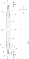
- Fig. 4 is a plan view of the cutting insert 3 shown in Fig. 3 from a side of the rake surface 7.
- the cutting edge 10 includes a curved corner cutting edge 13 and a pair of lateral cutting edges 11 and 12 disposed such that both ends 13L and 13R of the corner cutting edge 13 are sandwiched therebetween.
- the corner cutting edge 13 is formed in a circular arc shape.
- the shape of the corner cutting edge 13 is not limited to a circular arc shape, but may be an elliptical arc, a hyperbola, or a parabola.
- the pair of lateral cutting edges 11 and 12 are formed linearly in a plan view from a side of the rake surface 7.
- An angle ⁇ formed by the pair of lateral cutting edges 11 and 12 is an acute angle, preferably greater than or equal to 10° and less than or equal to 35°, and more preferably greater than or equal to 15° and less than or equal to 30°. In the illustrated example, the angle ⁇ is set to 15°. If the angle ⁇ is greater than or equal to 15°, both end portions (edge portions) 4 and 5 can be formed to have sufficient strength to be resistant to breakage even when used in lateral feed machining. If the angle ⁇ is less than or equal to 30°, the cutting edge 10 is unlikely to interfere with adjacent portions even when inserted into a narrow space.
- Fig. 5 is a bottom view of the cutting insert 3 shown in Fig. 3 from a side of the bottom surface 8.
- a corner flank 94 is formed on a cylindrical surface.
- the cutting insert 3 is formed, for example, in a substantially hexagonal shape in a bottom view from a side of the bottom surface 8.
- the cutting insert 3 has mirror-image symmetry with respect to a symmetry plane that is parallel to a YZ plane and bisects the cutting insert 3 in the longitudinal direction X. Furthermore, the cutting insert 3 also has mirror-image symmetry with respect to a symmetry plane that is parallel to a XY plane and bisects the cutting insert 3 in the width direction Z.
- Fig. 6 is a side view of the cutting insert 3 shown in Fig. 3 from a side of the first end 4E.
- the side surface 9 has, at a portion 93 abutting on the corner cutting edge 13, the corner flank 94 continuous with the corner cutting edge 13 and a flat surface 95 disposed closer to the bottom surface 8 than the corner flank 94 in the height direction Y.
- a second restrained portion 62 that comes into contact with the second restraining portion 22 of the tool body 2 is provided on the lower surface 6B of the body part 6.
- a third restrained portion 63 that comes into contact with the third restraining portion 23 of the tool body 2 is provided on the upper surface 6A of the body part 6.
- the second and third restrained portions 62 and 63 are recessed stripes extending in the longitudinal direction X and opposing each other in the height direction Y.
- the direction parallel to the upper surface 6A and lower surface 6B of the body part 6 may be referred to as the longitudinal direction X of the cutting insert 3, and the direction in which the second and third restrained portions 62 and 63 oppose each other may be referred to as the height direction Y.
- the second restrained portion 62 is formed as a recessed cylindrical surface that is recessed toward the third restrained portion 63
- the third restrained portion 63 is formed as a recessed cylindrical surface that is recessed toward the second restrained portion 62.
- the shape of the recessed stripes functioning as the second and third restrained portions 62 and 63 is not limited to the concave cylindrical surface, but may be a V-shaped groove extending in the longitudinal direction X. Since the recessed stripes of the second and third restrained portions 62 and 63 fit into projected stripes of the second and third restraining portions 22 and 23, the cutting insert 3 is less likely to move in the width direction Z even when a feed force of a cutting resistance acts.
- the lateral cutting edges 11 and 12 can be fed in the width direction Z to perform lateral feed machining.
- Fig. 7 is a side view of the cutting insert 3 shown in Fig. 3 in the width direction Z.
- the flat surface 95 is disposed closer to the bottom surface 8 than the corner flank 94 in the height direction Y and is configured as a retracted surface that is retracted closer to the second end 5E than the corner flank 94 in the longitudinal direction X.
- the side surface 9 may further have a step surface 96 connecting the retracted surface 95 and the corner flank 94.
- the rake surface 7 is inclined to proceed in a direction from the rake surface 7 toward the bottom surface 8 (hereinafter referred to as downward) in the height direction Y as it moves away from the first end 4E in the longitudinal direction X.
- a rake angle ⁇ of the corner cutting edge 13 formed by a virtual plane (a virtual reference plane) VPr parallel to both the longitudinal direction X and the width direction Z and the rake surface 7 is preferably greater than or equal to 5° and less than or equal to 20°.
- the rake angle ⁇ is 10°
- the rake surface 7 is formed as a flat surface.
- the rake surface 7 appears as a straight line proceeding downward in the height direction Y as it proceeds from the first end 4E to the second end 5E in the longitudinal direction X.
- the rake surface 7 may be formed as a curved surface.
- the rake angle ⁇ is an angle formed by a tangent to the rake surface 7 drawn at the first end 4E and the virtual plane VPr in a side view in the width direction Z.
- a land parallel to the longitudinal direction X may be formed between the cutting edge 10 and the rake surface 7.
- the rake angle ⁇ is an angle formed by a tangent to the rake surface 7 drawn at a boundary between the land and the rake surface 7 and the virtual plane VPr.
- the boundary between the land and the rake surface 7 is a portion at which a straight line parallel to the longitudinal direction X intersects with a straight line or curve inclined with respect to the longitudinal direction X in a side view in the width direction Z.
- an angle ⁇ formed by a virtual plane (a virtual finishing surface) Vms parallel to both the height direction Y and the width direction Z and the flat surface 95 is preferably greater than or equal to 0° and less than or equal to 10°.
- the angle ⁇ is 7.5°.
- the angle ⁇ of the flat surface 95 has a positive or negative value in the same direction as a clearance angle of the corner cutting edge 13 directly above the flat surface 95. That is, when the angle ⁇ is a positive value ( ⁇ > 0), the flat surface 95 is inclined in a direction approaching the second end 5E in the longitudinal direction X as it moves toward the bottom surface 8 in the height direction Y. When the angle ⁇ is a negative value ( ⁇ ⁇ 0), the flat surface 95 is inclined in a direction away from the second end 5E in the longitudinal direction X as it moves toward the bottom surface 8 in the height direction Y.
- Fig. 8 is a perspective view showing a state in which the flat surface 95 shown in Fig. 7 is in contact with the first restraining portion 21 of the tool body 2.
- the cutting insert 3 has a first restrained portion that is in contact with the first restraining portion 21 of the tool body 2 in a state in which the cutting insert 3 is mounted on the insert mounting seat 20.
- the flat surface 95 described above is an example of the first restrained portion.
- the first restraining portion 21 and the flat surface 95 are formed as flat surfaces parallel to each other.
- the combination of the first restraining portion 21 and the first restrained portion opposing the first restraining portion 21 is not limited to the illustrated example and may be formed as uneven surfaces that fit into each other.
- the first restrained portion 95 may be formed as a recessed cylindrical surface that is curved in a direction opposite to the corner cutting edge 13, and the first restraining portion 21 may be formed as a cylindrical surface having substantially the same diameter.
- a structure in which a notch is formed in the first restrained portion 95 and a projected part that fits into the notch is formed in the first restraining portion 21 may be used.
- Fig. 9 is a side view showing a modification example of the cutting insert 3 shown in Fig. 7 .
- the two-corner type cutting insert 3 is disposed such that the rake surface 7 provided at the first end portion 4 and the rake surface 7 provided at the second end portion 5 are opposite to each other in the height direction Y.
- the first restrained portions 95 are provided at positions offset from the corner flanks 94 at both the end portions 4 and 5, and thus the cutting insert 3 can be stably restrained by the tool body 2.
- the pair of lateral cutting edges 11 and 12 form an acute angle ⁇ and both the end portions 4 and 5 have a sharply pointed shape, and thus the cutting edge 10 can perform copy machining even in a narrow space without interfering with adjacent portions.
- the cutting insert has both the pointed end portions 4 and 5 each having the acute angle ⁇ , a large contact area can be secured between the first restraining portion 21 provided on the tool body 2 and the first restrained portion 95 provided on the cutting insert 3, and thus the cutting insert 3 can be stably restrained by the tool body 2. Since the cutting insert is a two corner type that allows the cutting edges 10 at both the end portions 4 and 5 to be used, it is highly economical.
Landscapes
- Engineering & Computer Science (AREA)
- Mechanical Engineering (AREA)
- Cutting Tools, Boring Holders, And Turrets (AREA)
- Milling Processes (AREA)
Abstract
Description
- The present invention relates to a two-corner type cutting insert and a turning tool provided with the cutting insert.
- There is a two-corner type cutting insert called a dog-bone type cutting insert, which has substantially a rod shape and has at both end portions thereof cutting edges (see, for example,
Patent Documents 1 to 4). Since a cutting insert having such a shape can perform grooving and cutting off as well as lateral feed machining, the cutting insert can be used for finishing and copy machining of a product. - A blisk, in which blades and a rotor disk are integrated in order to reduce weight and improve performance, is used in a turbine for a turbo pump mounted in an engine system for an aircraft, a space rocket, or the like. A labyrinth seal is often used as a seal to suppress fluid from leaking from a gap between the blisk that rotates due to fluid pressure and a stator which is stationary. Fin-like protrusions that constitute the labyrinth seal are machined on the surface of the blisk.
- A gap between adjacent protrusions on the surface of the blisk is designed to be narrow such that the protrusions machined on the blisk and the protrusions machined on the stator are intricately intertwined to provide sealing performance. The cutting inserts described in
Patent Documents 1 to 3 have at both end portions thereof circular or trapezoidal cutting edges. When an unmachined portion is machined with a cutting edge having such a shape, the cutting edge interferes with an adjacent machined portion, and thus it is not possible to machine a structure that includes a narrow gap. In machining the blisk, a form tool or insert that has a shape that replicates the gap between the protrusions of the labyrinth seal is used. -
- Patent Document 1:
Japanese Translation of PCT Application No. 2002-524272 - Patent Document 2: Patent Publication
JP-A-H8-229709 - Patent Document 3: Patent Publication
JP-A-2020-104243 - Patent Document 4: Patent Publication
JP-A-2006-198704 - However, the blisk, which is used in harsh environments where the blisk is constantly exposed to high temperatures, is made of a difficult-to-cut material such as a nickel-based alloy or titanium alloy. Since a cutting resistance is higher in form tool machining than in copy machining or the like, when the difficult-to-cut material is machined, machining defects (chattering) may occur due to vibration, or the protrusions may bend during machining to escape from the cutting edge, resulting in reduced machining accuracy. Since the sealing performance of the labyrinth seal affects the efficiency of the turbo pump, particularly strict machining precision is required for the machining of the protrusions inside the seal.
- Therefore, instead of the form tool (whole form bite) or the like, it is conceivable to use a cutting insert having a sharply pointed end portion that is less likely to interfere even when being inserted into a narrow space. If the gap between the protrusions is copy-machined using lateral feed machining, a cutting resistance is lower than in a case in which the form tool machining is performed, and the machining accuracy of the labyrinth seal is improved. Furthermore, since gaps having various shapes can be machined using cutting inserts having the same shape, there is no need to prepare form tools or the like for each shape of the protrusion. On the other hand, if both end portions of the cutting insert are sharply pointed, a contact area between a tool body and the cutting insert is small, and thus the cutting insert may not be stably restrained by the tool body. If a one-corner type cutting insert, in which a cutting edge is formed on only one end portion, is used, the other end, on which no cutting edge is formed, can be shaped specifically for restraint with the tool body to stabilize a restraint force, but running cost will increase compared to a two-corner type cutting insert.
- The present invention has been made in consideration of the above circumstances, and an object of the present invention is to provide a cutting insert or the like that is capable of copy machining in a narrow space and is also highly economical.
- A cutting insert according to one aspect of the present invention extends in a longitudinal direction from a first end to a second end on an opposite side to the first end. A first end portion that includes the first end and a portion in the vicinity thereof and a second end portion that includes the second end and a portion in the vicinity thereof are formed in substantially a same shape. The first end portion has a rake surface and a bottom surface disposed on opposite sides to each other in a height direction orthogonal to the longitudinal direction, a side surface connecting the rake surface and the bottom surface, and a cutting edge formed on an edge at which the rake surface and the side surface intersect. The cutting edge includes a curved corner cutting edge and a pair of lateral cutting edges disposed such that both ends of the corner cutting edge are sandwiched therebetween. The pair of lateral cutting edges are formed linearly and form an acute angle. The side surface has, at a portion abutting on the corner cutting edge, a corner flank continuous with the corner cutting edge and a flat surface disposed further toward the bottom surface than the corner flank in the height direction.
- According to this aspect, since the cutting insert has the pair of lateral cutting edges that form an acute angle, it is possible to perform copy machining in a narrow space. Since the cutting insert has the flat surface, a large contact area can be ensured between the cutting insert and the tool body when the cutting insert is designed as a two-corner type. It is more economical than a form tool for nongeneral purposes, a one-corner type cutting insert, or the like.
- In the aspect, in a side view in a width direction orthogonal to both the longitudinal direction and the height direction, a clearance angle formed by a virtual finishing plane parallel to both the height direction and the width direction, and the flat surface may be greater than or equal to 0° and less than or equal to 10°.
- According to this aspect, since an inclination of the flat surface that is supported by the tool body is small, the cutting insert is less likely to move in the height direction when a thrust force of a cutting resistance acts. The cutting insert can be stably restrained by the tool body.
- In the aspect, an angle formed by the pair of lateral cutting edges may be greater than or equal to 10° and less than or equal to 35°.
- According to this aspect, since the end portion has a sharply pointed shape, it is possible to perform copy machining even in a narrow space without the cutting edge interfering with adjacent portions.
- In the aspect, in a side view in a width direction orthogonal to both the longitudinal direction and the height direction, a rake angle of the corner cutting edge formed by a virtual reference plane parallel to both the longitudinal direction and the width direction, and the rake surface may be greater than or equal to 5° and less than or equal to 20°.
- According to this aspect, a large rake angle can be ensured, and a cutting resistance can be reduced. Even a difficult-to-cut material can be machined easily.
- A turning tool according to another aspect of the present invention includes a tool body and a cutting insert mounted on the tool body. The tool body has a plurality of restraining portions that come into contact with the cutting insert to restrain movement of the cutting insert. The cutting insert extends in a longitudinal direction from a first end to a second end on an opposite side to the first end, and a first end portion that includes the first end and a portion in the vicinity thereof and a second end portion that includes the second end and a portion in the vicinity thereof are formed in substantially a same shape. The first end portion has a rake surface and a bottom surface disposed on opposite sides to each other in a height direction orthogonal to the longitudinal direction, a side surface connecting the rake surface and the bottom surface, and a cutting edge formed on an edge at which the rake surface and the side surface intersect. The cutting edge includes a curved corner cutting edge and a pair of lateral cutting edges disposed such that both ends of the corner cutting edge are sandwiched therebetween. The pair of lateral cutting edges are formed linearly and form an acute angle. The side surface has, at a portion abutting on the corner cutting edge, a corner flank continuous with the corner cutting edge and a first restrained portion that is disposed further toward the bottom surface than the corner flank in the height direction and comes into contact with a first restraining portion of the plurality of restraining portions of the tool body. The first restraining portion and the first restrained portion are formed as flat surfaces parallel to each other or uneven surfaces that fit into each other.
- According to this aspect, the corresponding first restraining portion and first restrained portion come into contact with each other with a large contact area, and thus the cutting insert can be stably restrained to the tool body. It is possible to configure a turning tool equipped with a cutting insert that is capable of copy machining in a narrow space and is also highly economical.
- According to the present invention, it is possible to provide a cutting insert or the like that is capable of copy machining in a narrow space and is also highly economical.
-
-
Fig. 1 is a perspective view showing an example of a turning tool on which a cutting insert according to one embodiment of the present invention is mounted. -
Fig. 2 is a perspective view showing a restraining portion of a tool body with the cutting insert removed from the turning tool shown inFig. 1 . -
Fig. 3 is a perspective view showing an example of the cutting insert according to one embodiment of the present invention. -
Fig. 4 is a plan view of the cutting insert shown inFig. 3 from a side of a rake surface. -
Fig. 5 is a bottom view of the cutting insert shown inFig. 3 from a side of a bottom surface. -
Fig. 6 is a side view of the cutting insert shown inFig. 3 from a side of a first end. -
Fig. 7 is a side view of the cutting insert shown inFig. 3 in a width direction. -
Fig. 8 is a perspective view showing a state in which a first restrained portion shown inFig. 6 is in contact with a first restraining portion of the tool body. -
Fig. 9 is a side view showing a modification example of the cutting insert shown inFig. 7 . - A preferred embodiment of the present invention will be described with reference to the accompanying drawings. In each drawing, elements designated by the same reference signs have the same or similar configurations. Each configuration will be described in detail below with reference to the drawings.
Fig. 1 is a perspective view showing an example of aturning tool 1 on which acutting insert 3 according to one embodiment of the present invention is mounted. As shown inFig. 1 , theturning tool 1 includes atool body 2 and the cuttinginsert 3 mounted on thetool body 2. - In the following description, a longitudinal direction X of the cutting
insert 3 may be referred to as an X-axis direction, a height direction Y of the cuttinginsert 3 may be referred to as a Y-axis direction, and a width direction Z of the cuttinginsert 3 may be referred to as a Z-axis direction. An X axis, a Y axis, and a Z axis are orthogonal to each other. The longitudinal direction X is a direction parallel to a straight line passing through bothends insert 3. The height direction Y is a direction orthogonal to the longitudinal direction X, on opposite sides of which arake surface 7 and abottom surface 8 of the cuttinginsert 3 are disposed. The width direction Z is a direction orthogonal to both the longitudinal direction X and the height direction Y. -
Fig. 2 is a perspective view showing a restraining portion of thetool body 2 with the cuttinginsert 3 removed from theturning tool 1 shown inFig. 1 . As shown inFig. 2 , thetool body 2 is formed in substantially a rod shape extending from a base end to a leading end on a side opposite to the base end, and aninsert mounting seat 20 for mounting the cuttinginsert 3 is provided at a leading end portion including the leading end and the vicinity thereof. A portion closer to the base end than the leading end portion is configured as a shank that can be fixed to a machine tool. - The
insert mounting seat 20 is provided with a plurality of restraining portions that come into contact with the cuttinginsert 3 to restrain the movement of the cuttinginsert 3. In the illustrated example, thetool body 2 has first tothird restraining portions insert 3 can be restrained by or released from theinsert mounting seat 20 by tightening or loosening afastening screw 24. -
Fig. 3 is a perspective view showing an example of the cutting insert according to one embodiment of the present invention. As shown inFig. 3 , the cuttinginsert 3 is formed in substantially a rod shape using a hard material such as cemented carbide and extends in the longitudinal direction X from afirst end 4E to asecond end 5E on a side opposite to thefirst end 4E. - The cutting
insert 3 is a two-corner type havingcutting edges 10 formed at bothend portions first end portion 4 that includes thefirst end 4E and a portion in the vicinity thereof and asecond end portion 5 that includes thesecond end 5E and a portion in the vicinity thereof are formed in substantially the same shape. For this reason, thefirst end portion 4 will be described in detail as a representative example, and duplicate description of thesecond end portion 5 will be omitted. - As shown in
Fig. 3 , thefirst end portion 4 has therake surface 7 and thebottom surface 8 disposed on sides opposite to each other in the height direction Y orthogonal to the longitudinal direction X, aside surface 9 connecting therake surface 7 and thebottom surface 8, and thecutting edge 10 formed on an edge at which therake surface 7 and theside surface 9 intersect. The cuttinginsert 3 further has abody part 6 connecting the first end portion (a first edge portion) 4 and the second end portion (a second edge portion) 5. Therake surface 7 of thefirst end portion 4 and anupper surface 6A of thebody part 6 are connected by a gentlycurved surface 37. Thecurved surface 37 is inclined to proceed from alower surface 6B toward anupper surface 6A of thebody part 6 as it proceeds from thefirst end 4E toward thesecond end 5E. -
Fig. 4 is a plan view of the cuttinginsert 3 shown inFig. 3 from a side of therake surface 7. As shown inFig. 4 , thecutting edge 10 includes a curvedcorner cutting edge 13 and a pair of lateral cutting edges 11 and 12 disposed such that both ends 13L and 13R of thecorner cutting edge 13 are sandwiched therebetween. In the illustrated example, thecorner cutting edge 13 is formed in a circular arc shape. The shape of thecorner cutting edge 13 is not limited to a circular arc shape, but may be an elliptical arc, a hyperbola, or a parabola. - The pair of lateral cutting edges 11 and 12 are formed linearly in a plan view from a side of the
rake surface 7. An angle γ formed by the pair of lateral cutting edges 11 and 12 is an acute angle, preferably greater than or equal to 10° and less than or equal to 35°, and more preferably greater than or equal to 15° and less than or equal to 30°. In the illustrated example, the angle γ is set to 15°. If the angle γ is greater than or equal to 15°, both end portions (edge portions) 4 and 5 can be formed to have sufficient strength to be resistant to breakage even when used in lateral feed machining. If the angle γ is less than or equal to 30°, thecutting edge 10 is unlikely to interfere with adjacent portions even when inserted into a narrow space. -
Fig. 5 is a bottom view of the cuttinginsert 3 shown inFig. 3 from a side of thebottom surface 8. In the illustrated example, acorner flank 94 is formed on a cylindrical surface. The cuttinginsert 3 is formed, for example, in a substantially hexagonal shape in a bottom view from a side of thebottom surface 8. - As described above, the
first end portion 4 and thesecond end portion 5 have substantially the same shape and function. The cuttinginsert 3 has mirror-image symmetry with respect to a symmetry plane that is parallel to a YZ plane and bisects the cuttinginsert 3 in the longitudinal direction X. Furthermore, the cuttinginsert 3 also has mirror-image symmetry with respect to a symmetry plane that is parallel to a XY plane and bisects the cuttinginsert 3 in the width direction Z. -
Fig. 6 is a side view of the cuttinginsert 3 shown inFig. 3 from a side of thefirst end 4E. As shown inFig. 6 , theside surface 9 has, at aportion 93 abutting on thecorner cutting edge 13, thecorner flank 94 continuous with thecorner cutting edge 13 and aflat surface 95 disposed closer to thebottom surface 8 than thecorner flank 94 in the height direction Y. - A second restrained
portion 62 that comes into contact with thesecond restraining portion 22 of thetool body 2 is provided on thelower surface 6B of thebody part 6. A thirdrestrained portion 63 that comes into contact with the third restrainingportion 23 of thetool body 2 is provided on theupper surface 6A of thebody part 6. The second and thirdrestrained portions upper surface 6A andlower surface 6B of thebody part 6 may be referred to as the longitudinal direction X of the cuttinginsert 3, and the direction in which the second and thirdrestrained portions - In the illustrated example, the second
restrained portion 62 is formed as a recessed cylindrical surface that is recessed toward the thirdrestrained portion 63, and the thirdrestrained portion 63 is formed as a recessed cylindrical surface that is recessed toward the secondrestrained portion 62. The shape of the recessed stripes functioning as the second and thirdrestrained portions restrained portions third restraining portions insert 3 is less likely to move in the width direction Z even when a feed force of a cutting resistance acts. The lateral cutting edges 11 and 12 can be fed in the width direction Z to perform lateral feed machining. -
Fig. 7 is a side view of the cuttinginsert 3 shown inFig. 3 in the width direction Z. As shown inFig. 7 , in theportion 93 abutting on thecorner cutting edge 13, theflat surface 95 is disposed closer to thebottom surface 8 than thecorner flank 94 in the height direction Y and is configured as a retracted surface that is retracted closer to thesecond end 5E than thecorner flank 94 in the longitudinal direction X. Theside surface 9 may further have astep surface 96 connecting the retractedsurface 95 and thecorner flank 94. - The
rake surface 7 is inclined to proceed in a direction from therake surface 7 toward the bottom surface 8 (hereinafter referred to as downward) in the height direction Y as it moves away from thefirst end 4E in the longitudinal direction X. As shown inFig. 7 , in a side view in the width direction Z, a rake angle α of thecorner cutting edge 13 formed by a virtual plane (a virtual reference plane) VPr parallel to both the longitudinal direction X and the width direction Z and therake surface 7 is preferably greater than or equal to 5° and less than or equal to 20°. In the illustrated example, the rake angle α is 10°, and therake surface 7 is formed as a flat surface. In a side view in the width direction Z, therake surface 7 appears as a straight line proceeding downward in the height direction Y as it proceeds from thefirst end 4E to thesecond end 5E in the longitudinal direction X. - The
rake surface 7 may be formed as a curved surface. In this case, the rake angle α is an angle formed by a tangent to therake surface 7 drawn at thefirst end 4E and the virtual plane VPr in a side view in the width direction Z. A land parallel to the longitudinal direction X may be formed between the cuttingedge 10 and therake surface 7. In this case, the rake angle α is an angle formed by a tangent to therake surface 7 drawn at a boundary between the land and therake surface 7 and the virtual plane VPr. The boundary between the land and therake surface 7 is a portion at which a straight line parallel to the longitudinal direction X intersects with a straight line or curve inclined with respect to the longitudinal direction X in a side view in the width direction Z. - As shown in
Fig. 7 , in a side view in the width direction Z, an angle β formed by a virtual plane (a virtual finishing surface) Vms parallel to both the height direction Y and the width direction Z and theflat surface 95 is preferably greater than or equal to 0° and less than or equal to 10°. In the illustrated example, the angle β is 7.5°. In the present specification, the angle β of theflat surface 95 has a positive or negative value in the same direction as a clearance angle of thecorner cutting edge 13 directly above theflat surface 95. That is, when the angle β is a positive value (β > 0), theflat surface 95 is inclined in a direction approaching thesecond end 5E in the longitudinal direction X as it moves toward thebottom surface 8 in the height direction Y. When the angle β is a negative value (β < 0), theflat surface 95 is inclined in a direction away from thesecond end 5E in the longitudinal direction X as it moves toward thebottom surface 8 in the height direction Y. -
Fig. 8 is a perspective view showing a state in which theflat surface 95 shown inFig. 7 is in contact with the first restrainingportion 21 of thetool body 2. The cuttinginsert 3 has a first restrained portion that is in contact with the first restrainingportion 21 of thetool body 2 in a state in which thecutting insert 3 is mounted on theinsert mounting seat 20. Theflat surface 95 described above is an example of the first restrained portion. As shown inFig. 8 , the first restrainingportion 21 and theflat surface 95 are formed as flat surfaces parallel to each other. - The combination of the first restraining
portion 21 and the first restrained portion opposing the first restrainingportion 21 is not limited to the illustrated example and may be formed as uneven surfaces that fit into each other. For example, the firstrestrained portion 95 may be formed as a recessed cylindrical surface that is curved in a direction opposite to thecorner cutting edge 13, and the first restrainingportion 21 may be formed as a cylindrical surface having substantially the same diameter. For example, a structure in which a notch is formed in the firstrestrained portion 95 and a projected part that fits into the notch is formed in the first restrainingportion 21 may be used. -
Fig. 9 is a side view showing a modification example of the cuttinginsert 3 shown inFig. 7 . In the illustrated example, the two-cornertype cutting insert 3 is disposed such that therake surface 7 provided at thefirst end portion 4 and therake surface 7 provided at thesecond end portion 5 are opposite to each other in the height direction Y. Even in such a modification example, the firstrestrained portions 95 are provided at positions offset from the corner flanks 94 at both theend portions insert 3 can be stably restrained by thetool body 2. - According to the cutting
insert 3 of the present embodiment configured as described above and theturning tool 1 equipped with the cuttinginsert 3, the pair of lateral cutting edges 11 and 12 form an acute angle γ and both theend portions cutting edge 10 can perform copy machining even in a narrow space without interfering with adjacent portions. Even though the cutting insert has both thepointed end portions portion 21 provided on thetool body 2 and the firstrestrained portion 95 provided on the cuttinginsert 3, and thus the cuttinginsert 3 can be stably restrained by thetool body 2. Since the cutting insert is a two corner type that allows the cutting edges 10 at both theend portions - The above-described embodiments are intended to facilitate understanding of the present invention and are not intended to limit the present invention. The elements of the embodiments as well as their arrangement, materials, conditions, shapes, sizes, and the like are not limited to those exemplified and can be modified as appropriate. Furthermore, configurations shown in different embodiments may be partially substituted or combined with each other.
-
- 1
- Turning tool
- 2
- Tool body
- 3
- Cutting insert
- 4
- First end portion
- 4E
- First end
- 5
- Second end portion
- 5E
- Second end
- 6
- Body part
- 6A
- Upper surface
- 6B
- Lower surface
- 7
- Rake surface
- 8
- Bottom surface
- 9
- Side surface
- 10
- Cutting edge
- 11
- One lateral cutting edge
- 12
- Another lateral cutting edge
- 13
- Corner cutting edge
- 13L, 13R
- Both ends of corner cutting edge
- 20
- Insert mounting seat
- 21
- First restraining portion
- 22
- Second restraining portion
- 23
- Third restraining portion
- 24
- Fastening screw
- 37
- Curved surface
- 62
- Second restrained portion
- 63
- Third restrained portion
- 91
- Flank of one lateral cutting edge
- 92
- Flank of another lateral cutting edge
- 93
- Portion abutting on corner cutting edge
- 94
- Corner flank
- 95
- Flat surface (example of first restrained portion)
- 96
- Step surface
- Vms
- Virtual finishing surface
- VPr
- Virtual reference plane
- X
- Longitudinal direction
- Y
- Height direction
- Z
- Width direction
- α
- Rake angle of corner cutting edge
- β
- Inclination angle of first restraining portion
- γ
- Crossing angle of lateral cutting edges
Claims (5)
- A cutting insert extending in a longitudinal direction from a first end to a second end on an opposite side to the first end,wherein a first end portion that includes the first end and a portion in the vicinity thereof and a second end portion that includes the second end and a portion in the vicinity thereof are formed in substantially a same shape,wherein the first end portion has a rake surface and a bottom surface disposed on opposite sides to each other in a height direction orthogonal to the longitudinal direction, a side surface connecting the rake surface and the bottom surface, and a cutting edge formed on an edge at which the rake surface and the side surface intersect,wherein the cutting edge includes a curved corner cutting edge and a pair of lateral cutting edges disposed such that both ends of the corner cutting edge are sandwiched therebetween,wherein the pair of lateral cutting edges are formed linearly and form an acute angle, andwherein the side surface has, at a portion abutting on the corner cutting edge, a corner flank continuous with the corner cutting edge and a flat surface disposed further toward the bottom surface than the corner flank in the height direction.
- The cutting insert according to claim 1, wherein, in a side view in a width direction orthogonal to both the longitudinal direction and the height direction,
an angle formed by a virtual plane parallel to both the height direction and the width direction, and the flat surface is greater than or equal to 0° and less than or equal to 10°. - The cutting insert according to claim 1 or 2, wherein an angle formed by the pair of lateral cutting edges is greater than or equal to 10° and less than or equal to 35°.
- The cutting insert according to any one of claims 1 to 3, wherein, in a side view in a width direction orthogonal to both the longitudinal direction and the height direction,
a rake angle of the corner cutting edge formed by a virtual plane parallel to both the longitudinal direction and the width direction, and the rake surface is greater than or equal to 5° and less than or equal to 20°. - A turning tool comprising a tool body and a cutting insert mounted on the tool body,wherein the tool body has a plurality of restraining portions that come into contact with the cutting insert to restrain movement of the cutting insert,wherein the cutting insert extends in a longitudinal direction from a first end to a second end on an opposite side to the first end,wherein a first end portion that includes the first end and a portion in the vicinity thereof and a second end portion that includes the second end and a portion in the vicinity thereof are formed in substantially the same shape,wherein the first end portion has a rake surface and a bottom surface disposed on sides opposite to each other in a height direction orthogonal to the longitudinal direction, a side surface connecting the rake surface and the bottom surface, and a cutting edge formed on an edge at which the rake surface and the side surface intersect,wherein the cutting edge includes a curved corner cutting edge and a pair of lateral cutting edges disposed such that both ends of the corner cutting edge are sandwiched therebetween,wherein the pair of lateral cutting edges are formed linearly and form an acute angle,wherein the side surface has, at a portion abutting on the corner cutting edge, a corner flank continuous with the corner cutting edge and a first restrained portion that is disposed further toward the bottom surface than the corner flank in the height direction and comes into contact with a first restraining portion of the plurality of restraining portions of the tool body, andwherein the first restraining portion and the first restrained portion are formed as flat surfaces parallel to each other or uneven surfaces that fit into each other.
Applications Claiming Priority (2)
| Application Number | Priority Date | Filing Date | Title |
|---|---|---|---|
| JP2022047256A JP7112684B1 (en) | 2022-03-23 | 2022-03-23 | Cutting inserts and turning tools |
| PCT/JP2023/008468 WO2023181901A1 (en) | 2022-03-23 | 2023-03-07 | Cutting insert and turning tool |
Publications (2)
| Publication Number | Publication Date |
|---|---|
| EP4497523A1 true EP4497523A1 (en) | 2025-01-29 |
| EP4497523A4 EP4497523A4 (en) | 2026-03-11 |
Family
ID=82702017
Family Applications (1)
| Application Number | Title | Priority Date | Filing Date |
|---|---|---|---|
| EP23774500.5A Pending EP4497523A4 (en) | 2022-03-23 | 2023-03-07 | Cutting insert and turning tool |
Country Status (5)
| Country | Link |
|---|---|
| US (1) | US20250187078A1 (en) |
| EP (1) | EP4497523A4 (en) |
| JP (1) | JP7112684B1 (en) |
| CN (1) | CN118660774A (en) |
| WO (1) | WO2023181901A1 (en) |
Family Cites Families (13)
| Publication number | Priority date | Publication date | Assignee | Title |
|---|---|---|---|---|
| JPH08229709A (en) | 1995-02-24 | 1996-09-10 | Toshiba Tungaloy Co Ltd | Throw away tip for grooving |
| SE514872C2 (en) | 1998-09-09 | 2001-05-07 | Sandvik Ab | Cutter for track turning |
| IL159188A (en) | 2003-12-04 | 2008-08-07 | Uzi Gati | Cutting insert for grooving operations |
| JP4424209B2 (en) | 2005-01-19 | 2010-03-03 | 三菱マテリアル株式会社 | Cutting insert clamping mechanism |
| JP5157660B2 (en) | 2008-06-09 | 2013-03-06 | 三菱マテリアル株式会社 | Cutting insert and insert detachable cutting tool |
| JP5343600B2 (en) | 2009-02-10 | 2013-11-13 | 三菱マテリアル株式会社 | Cutting insert |
| JP5768516B2 (en) | 2011-06-10 | 2015-08-26 | 三菱マテリアル株式会社 | Cutting insert manufacturing method and cutting insert |
| US10239125B2 (en) * | 2015-05-26 | 2019-03-26 | Kyocera Corporation | Cutting insert, cutting tool, and method for manufacturing machined product using same |
| JP6877921B2 (en) | 2016-09-02 | 2021-05-26 | 京セラ株式会社 | Manufacturing method for cutting inserts, cutting tools and cutting products |
| JP2018149617A (en) | 2017-03-10 | 2018-09-27 | 三菱マテリアル株式会社 | Blade edge replaceable cutting tool |
| JP6936975B2 (en) | 2018-12-28 | 2021-09-22 | 株式会社タンガロイ | Cutting inserts and cutting tools |
| CN113474110B (en) * | 2019-03-05 | 2024-06-04 | 京瓷株式会社 | Turning tool and method for manufacturing cut product |
| CN115666827B (en) * | 2020-05-21 | 2026-03-20 | 京瓷株式会社 | Methods for manufacturing cutting inserts, cutting tools and workpieces |
-
2022
- 2022-03-23 JP JP2022047256A patent/JP7112684B1/en active Active
-
2023
- 2023-03-07 EP EP23774500.5A patent/EP4497523A4/en active Pending
- 2023-03-07 CN CN202380021007.9A patent/CN118660774A/en active Pending
- 2023-03-07 US US18/845,279 patent/US20250187078A1/en active Pending
- 2023-03-07 WO PCT/JP2023/008468 patent/WO2023181901A1/en not_active Ceased
Also Published As
| Publication number | Publication date |
|---|---|
| JP7112684B1 (en) | 2022-08-04 |
| JP2023141115A (en) | 2023-10-05 |
| WO2023181901A1 (en) | 2023-09-28 |
| EP4497523A4 (en) | 2026-03-11 |
| CN118660774A (en) | 2024-09-17 |
| US20250187078A1 (en) | 2025-06-12 |
Similar Documents
| Publication | Publication Date | Title |
|---|---|---|
| CN102066029B (en) | Cutting insert, cutting tool, and cutting method using cutting insert and cutting tool | |
| KR100289094B1 (en) | Cutting insert for milling cutter | |
| CN101668604B (en) | Cutting insert, cutting tool, and cutting method using the same | |
| EP2682212B1 (en) | Guide pad and cutting tool | |
| JP5159773B2 (en) | Cutting insert, cutting tool, and cutting method using the same | |
| JP6330913B2 (en) | Cutting insert and cutting edge exchangeable rotary cutting tool | |
| EP2101947B1 (en) | Cutting insert and cutting tool | |
| KR101569551B1 (en) | Milling cutter and cutting insert therefor | |
| CN107107209A (en) | Cutting tip and milling cutter | |
| US11179785B2 (en) | Cutting insert and indexable edge rotary cutting tool | |
| JP7197576B2 (en) | Double-sided indexable insert with tapered waist for high-feed milling and drilling, high-feed or drilling tools | |
| JP6470043B2 (en) | Turning tool | |
| CN101522350A (en) | Cutting insert, cutting tool using the same, and cutting method | |
| EP2682211A1 (en) | Guide pad, cutting tool body, and cutting tool | |
| US9511426B2 (en) | Cutting insert, tool body on which said cutting insert may be mounted, and replaceable-blade-type ball-end mill provided therewith | |
| KR20180018547A (en) | An assembly comprising a lozenge insert and a support mount and a diamond-shaped reversible cutting insert | |
| EP4497523A1 (en) | Cutting insert and turning tool | |
| EP3338929A1 (en) | Cutting insert | |
| CN108883478B (en) | cutting insert | |
| CN111867767B (en) | Cutting insert and cutting tool having the same mounted thereon | |
| EP4691675A1 (en) | Cutting insert, and indexable cutting edge type rotary cutting tool | |
| RU2838657C2 (en) | Lathe tool | |
| KR950004668B1 (en) | Insert cutter | |
| EP4691674A1 (en) | Cutting insert and replaceable-edge rotary cutting tool | |
| EP4670878A1 (en) | Cutting insert for turning and turning tool |
Legal Events
| Date | Code | Title | Description |
|---|---|---|---|
| STAA | Information on the status of an ep patent application or granted ep patent |
Free format text: STATUS: THE INTERNATIONAL PUBLICATION HAS BEEN MADE |
|
| PUAI | Public reference made under article 153(3) epc to a published international application that has entered the european phase |
Free format text: ORIGINAL CODE: 0009012 |
|
| STAA | Information on the status of an ep patent application or granted ep patent |
Free format text: STATUS: REQUEST FOR EXAMINATION WAS MADE |
|
| 17P | Request for examination filed |
Effective date: 20240930 |
|
| AK | Designated contracting states |
Kind code of ref document: A1 Designated state(s): AL AT BE BG CH CY CZ DE DK EE ES FI FR GB GR HR HU IE IS IT LI LT LU LV MC ME MK MT NL NO PL PT RO RS SE SI SK SM TR |
|
| DAV | Request for validation of the european patent (deleted) | ||
| DAX | Request for extension of the european patent (deleted) | ||
| A4 | Supplementary search report drawn up and despatched |
Effective date: 20260210 |
|
| RIC1 | Information provided on ipc code assigned before grant |
Ipc: B23B 27/16 20060101AFI20260204BHEP Ipc: B23B 27/04 20060101ALI20260204BHEP Ipc: B23B 27/14 20060101ALI20260204BHEP Ipc: B23B 29/04 20060101ALN20260204BHEP |