EP4497401A1 - Rotierende atherektomievorrichtung und rotierende atherektomievorrichtung - Google Patents
Rotierende atherektomievorrichtung und rotierende atherektomievorrichtung Download PDFInfo
- Publication number
- EP4497401A1 EP4497401A1 EP23814976.9A EP23814976A EP4497401A1 EP 4497401 A1 EP4497401 A1 EP 4497401A1 EP 23814976 A EP23814976 A EP 23814976A EP 4497401 A1 EP4497401 A1 EP 4497401A1
- Authority
- EP
- European Patent Office
- Prior art keywords
- rotating abrasive
- abrasive head
- diameter
- proximal
- rotational atherectomy
- Prior art date
- Legal status (The legal status is an assumption and is not a legal conclusion. Google has not performed a legal analysis and makes no representation as to the accuracy of the status listed.)
- Pending
Links
Images

Classifications
-
- A—HUMAN NECESSITIES
- A61—MEDICAL OR VETERINARY SCIENCE; HYGIENE
- A61B—DIAGNOSIS; SURGERY; IDENTIFICATION
- A61B17/00—Surgical instruments, devices or methods
- A61B17/32—Surgical cutting instruments
- A61B17/3205—Excision instruments
- A61B17/3207—Atherectomy devices working by cutting or abrading; Similar devices specially adapted for non-vascular obstructions
- A61B17/320758—Atherectomy devices working by cutting or abrading; Similar devices specially adapted for non-vascular obstructions with a rotating cutting instrument, e.g. motor driven
-
- A—HUMAN NECESSITIES
- A61—MEDICAL OR VETERINARY SCIENCE; HYGIENE
- A61B—DIAGNOSIS; SURGERY; IDENTIFICATION
- A61B17/00—Surgical instruments, devices or methods
- A61B2017/00743—Type of operation; Specification of treatment sites
- A61B2017/00778—Operations on blood vessels
-
- A—HUMAN NECESSITIES
- A61—MEDICAL OR VETERINARY SCIENCE; HYGIENE
- A61B—DIAGNOSIS; SURGERY; IDENTIFICATION
- A61B17/00—Surgical instruments, devices or methods
- A61B17/32—Surgical cutting instruments
- A61B2017/320004—Surgical cutting instruments abrasive
-
- A—HUMAN NECESSITIES
- A61—MEDICAL OR VETERINARY SCIENCE; HYGIENE
- A61B—DIAGNOSIS; SURGERY; IDENTIFICATION
- A61B17/00—Surgical instruments, devices or methods
- A61B17/32—Surgical cutting instruments
- A61B17/3205—Excision instruments
- A61B17/3207—Atherectomy devices working by cutting or abrading; Similar devices specially adapted for non-vascular obstructions
- A61B2017/320741—Atherectomy devices working by cutting or abrading; Similar devices specially adapted for non-vascular obstructions for stripping the intima or the internal plaque from a blood vessel, e.g. for endarterectomy
-
- A—HUMAN NECESSITIES
- A61—MEDICAL OR VETERINARY SCIENCE; HYGIENE
- A61B—DIAGNOSIS; SURGERY; IDENTIFICATION
- A61B17/00—Surgical instruments, devices or methods
- A61B17/32—Surgical cutting instruments
- A61B17/3205—Excision instruments
- A61B17/3207—Atherectomy devices working by cutting or abrading; Similar devices specially adapted for non-vascular obstructions
- A61B17/320758—Atherectomy devices working by cutting or abrading; Similar devices specially adapted for non-vascular obstructions with a rotating cutting instrument, e.g. motor driven
- A61B2017/320766—Atherectomy devices working by cutting or abrading; Similar devices specially adapted for non-vascular obstructions with a rotating cutting instrument, e.g. motor driven eccentric
Definitions
- the present invention relates to the field of medical devices, and particularly to a rotational atherectomy device and a rotational atherectomy apparatus.
- Atherosclerotic plaques are generally present in the coronary or peripheral vasculature and may have different characteristics depending on the texture. Heavily calcified lesions may require atherectomy pretreatment using a rotational atherectomy device, which can remove a calcified or fibrotic atherosclerotic plaque within a blood vessel by high-speed rotation and abrasion, thereby recanalizing the occluded blood vessel.
- the enlarged and smoothed vascular lumen allows easier subsequent implantation of a stent.
- Existing rotational atherectomy devices mainly include a flexible drive shaft and a rotating abrasive head supported on the flexible drive shaft.
- the drive shaft drives high-speed rotation of the rotating abrasive head while pushing it forward into contact with and through a plaque, thereby abrading it away.
- the rotating abrasive head has a diameter not less than a diameter of the drive shaft.
- the rotating abrasive head is mostly disposed over a middle section of the drive shaft. In this case, there is a non-abrasive section of the drive shaft distally ahead of the rotating abrasive head, and this distal drive shaft section must be screwed or pushed through a stenotic lesion before the middle rotating abrasive head can be brought into contact with the lesion.
- the distal drive shaft section may get stuck in the stenotic lesion during its screwing or pushing therethrough. This is risky and may even cause damage to the blood vessel due to excessive dilation.
- some lesions may be very stenotic or even completely occluded, and in these cases, it may be even difficult to bring the middle rotating abrasive head into contact with a lesion for abrasive atherectomy.
- the rotating abrasive head may not be coated with an abrasive material over its entire surface and may therefore not be capable of atherectomy in both axial directions.
- the conventional rotating abrasive head cannot be adjusted in diameter during atherectomy of a lesion. Therefore, such atherectomy procedures typically involve the sequential use of multiple rotating abrasive heads in an order from the smallest diameter to the largest diameter. This, however, necessitates frequent interchanging of associated rotational atherectomy devices of different sizes, increasing the surgical time and the probability of blood vessel damage.
- a large rotating abrasive head diameter may add challenges to passage through a narrow blood vessel or catheter and arrival at a target vascular lesion in a surgical procedure, and may block blood flow in a stenotic blood vessel, as well as distal flow of a liquid coolant and/or lubricant.
- Some conventional rotational atherectomy devices include multiple rotating abrasive heads sequentially disposed over a middle drive shaft section from distal to proximal in an increasing diameter order. Although this can circumvent frequent interchanging, it requires the drive shaft to have an increased axial length. As a consequence, normal blood vessel segments on distal and proximal sides of the target lesion tend to be affected during atherectomy. Moreover, the problems of blocked blood flow and blocked flow of a liquid coolant and/or lubricant remain unsolved due to possible excessively large diameters of one or more proximal ones of the rotating abrasive heads. In some of these conventional devices, the multiple rotating abrasive heads are disposed eccentrically.
- the present invention provides a rotational atherectomy device including a drive shaft and a rotating abrasive head, the drive shaft having a distal connecting portion connected to the rotating abrasive head, the rotating abrasive head and the drive shaft separately defining hollow cavities axially extending therethrough, the hollow cavities configured for insertion of a guide body therethrough, wherein a centroid of a structure consisting of the rotating abrasive head and the connecting portion connected thereto does not coincide with center axes of the hollow cavities.
- the rotating abrasive head has a distal portion, which has a diameter gradually increasing along its axis from distal to proximal and is coated on its outer surface with an abrasive layer.
- the rotating abrasive head has a proximal portion, which has a diameter gradually decreasing along its axis from distal to proximal and is coated on its outer surface with the abrasive layer. Additionally or alternatively, an intermediate portion of the rotating abrasive head between the distal and proximal portions is coated on its outer surface with the abrasive layer.
- the intermediate portion has a constant diameter or a diameter gradually increasing and then gradually decreasing along its axis from distal to proximal.
- the rotating abrasive head includes a base, which defines the hollow cavity of the rotating abrasive head and is coated on its outer surface with the abrasive layer.
- the abrasive layer is made of abrasive grains made of one or more abrasive materials.
- the abrasive layer has a thickness of 20-120 ⁇ m, such as 20 ⁇ m, 40 ⁇ m, 50 ⁇ m or 100 ⁇ m.
- the rotating abrasive head has a diameter gradually decreasing along its axis both distally and proximally. Accordingly, the rotating abrasive head may, for example, be shaped like a spindle wider in the middle and tapering toward the ends. Moreover, the rotating abrasive head may have a smooth outer surface.
- the rotating abrasive head includes at least one of:
- the rotational atherectomy device further includes the guide body, wherein the rotating abrasive head and the drive shaft are rotatable and axially movable relative to the guide body.
- the hollow cavity of the rotating abrasive head consists of distal and proximal hollow cavity sections in communication with each other, the distal hollow cavity section having a diameter matching a diameter of the guide body, the proximal hollow cavity section having a diameter greater than the diameter of the distal hollow cavity section, the proximal hollow cavity section secured to the connecting portion.
- the drive shaft is generally a hollow tubular structure with a constant diameter and has a center axis coincident with a center axis of the guide body.
- the drive shaft is a hollow tubular structure with a varying diameter, wherein the connecting portion has a diameter increasing along its axis from proximal to distal, and wherein the drive shaft further has a constant-diameter section joined to a proximal end of the connecting portion, the constant-diameter section having a center axis coincident with a center axis of the guide body.
- the connecting portion is inserted into the proximal hollow cavity section through a proximal opening of the rotating abrasive head, the proximal opening having a radial dimension smaller than or equal to a diameter of the connecting portion at its proximal end.
- the rotating abrasive head is spindle-shaped, wherein the proximal hollow cavity section has a matching spindle-like shape, and the connecting portion has a similar spindle-like shape complementary to that of the proximal hollow cavity section.
- the rotating abrasive head may be configured as a hollow shell. This allows the rotating abrasive head to have a reduced weight, which can mitigate the influence of a centrifugal force on movement of the rotating abrasive head.
- the present invention also provides a rotational atherectomy apparatus including a drive device and the rotational atherectomy device as defined above.
- the drive device is coupled to the drive shaft in the rotational atherectomy device and configured to actuate rotation of the rotational atherectomy device.
- the present invention provides a rotational atherectomy device and a rotational atherectomy apparatus.
- the rotational atherectomy device includes a drive shaft and a rotating abrasive head.
- the drive shaft has a distal connecting portion coupled to the rotating abrasive head.
- the rotating abrasive head and the drive shaft separately define hollow cavities axially extending therethrough.
- the hollow cavities are configured for insertion of a guide body therethrough.
- a centroid of a structure consisting of the rotating abrasive head and the connecting portion coupled thereto does not coincide with center axes of the hollow cavities.
- the rotating abrasive head is allowed to have a smaller static diameter (i.e., a diameter in a non-rotating state), which enables the rotational atherectomy device to be more easily advanced through a narrow blood vessel and catheter to a target vascular lesion, reducing surgical difficulties and improving surgical treatment.
- the drive shaft is allowed to have a reduced axial length, which mitigates the influence of the drive shaft on distal side of a lesion in need of atherectomy and normal blood vessel segments on proximal side.
- the single rotating abrasive head is eccentrically disposed to allow for controlled centrifugation during atherectomy, which does not adversely affect movement of the rotating abrasive head or a blood vessel. In this way, uncertainties associated with a surgical procedure using the device can be reduced, increasing safety of the surgical procedure.
- the use of only one rotating abrasive head does not increase overall stiffness of the drive shaft and ensures that it is compliant enough to facilitate its advancement through a blood vessel and catheter.
- the distal portion of the rotating abrasive head is preferred to have a diameter gradually increasing along its axis from distal to proximal, and the outer surface of the distal portion of the rotating abrasive head is coated with an abrasive layer.
- This abrasive layer on the distal portion of the rotating abrasive head may be directly brought into contact with a lesion in need of atherectomy and can thereby abrade the lesion more efficiently.
- distal refers to a side away from an operator operating a rotational atherectomy apparatus, while “proximal” refers to a side closer to the operator.
- Axial refers to a direction along a center axis of the rotational atherectomy apparatus, or of a rotational atherectomy device thereof, while “circumferential” refers to a direction about the axis.
- the center axis is oriented in a lengthwise direction of the rotational atherectomy device, or of a blood vessel in which the device is deployed.
- the term “diameter” refers to an outer diameter of a structure. A diameter of a rotating abrasive head includes that of an abrasive layer thereof.
- a rotational atherectomy apparatus and a rotational atherectomy device thereof.
- the rotational atherectomy apparatus includes a rotational atherectomy device 10 and a drive device (not shown).
- the drive device is coupled to a proximal end of a drive shaft 12 in the rotational atherectomy device 10 and is thereby able to actuate rotation of the rotational atherectomy device 10.
- the rotational atherectomy apparatus and the rotational atherectomy device thereof are used for vascular surgery for, for example, removing tissue from a body channel.
- the rotational atherectomy device may be used to remove a calcified or fibrotic atherosclerotic plaque from a blood vessel (e.g., a coronary, peripheral or other blood vessel), thereby recanalizing the blood vessel occluded by the plaque and smoothing its inner side.
- a blood vessel e.g., a coronary, peripheral or other blood vessel
- the rotational atherectomy device 10 includes a rotating abrasive head 11 and the drive shaft 12.
- the drive shaft 12 has a distal connecting portion 121, and the rotating abrasive head 11 is coupled to the connecting portion 121.
- the rotating abrasive head 11 and the drive shaft 12 are separately fabricated and then assembled together.
- the drive shaft 12 is an integral one-piece structure.
- the drive shaft 12 is a flexible drive shaft, which may be implemented as a spring coil.
- the drive shaft 12 may be actuated by the drive device to rotate, causing rotation of the rotating abrasive head 11.
- the rotating abrasive head 11 is disposed at the distal end of the drive shaft 12.
- the rotating abrasive head 11 can first come into contact with a vascular lesion and drill into a stenotic portion thereof, overcoming the problem associated with the conventional device that the middle rotating abrasive head can come into contact with a stenotic lesion only after a distal section of the drive shaft is screwed or pushed through the lesion. Therefore, the present invention can achieve better atherectomy performance and crossability can be achieved and reduce the risk associated with a surgical procedure.
- both the rotating abrasive head 11 and the drive shaft 12 define hollow cavities axial extending therethrough, a guide body 13 can be inserted through the hollow cavities of the rotating abrasive head 11 and the drive shaft 12.
- the guide body 13 may be, for example, a guidewire for guiding the rotational atherectomy device 10 through a diseased blood vessel. Center axes of the hollow cavities of the rotating abrasive head 11 and the drive shaft 12 coincide with each other.
- the rotating abrasive head 11 may be coupled to the connecting portion 121 so that a centroid 14 of the resulting coupled structure does not coincide with the center axes of the hollow cavities.
- the rotating abrasive head 11 and the drive shaft 12 are spun about the center axes of the hollow cavities, the rotating abrasive head 11 will also revolve under the action of a centrifugal force about an axis deviated from the center axes of the hollow cavities.
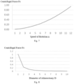
- speeding up the rotation of the rotating abrasive head 11 i.e., increasing its speed of rotation n
- can increase the diameter of revolution of the rotating abrasive head 11 i.e., its diameter of atherectomy D).
- the diameter of atherectomy D is greater than a static diameter of the rotating abrasive head 11.
- the rotating abrasive head 11 can adapt the diameter of atherectomy D to lesions of various sizes in need of atherectomy and recanalization. In this way, it can remove various lesions in a desired manner, while avoiding the use of multiple rotating abrasive heads of different sizes and hence frequent interchanging of them. This allows a surgical procedure using the device to be completed within a shorter time and associated with a lower risk.
- the single rotating abrasive head 11 since only one rotating abrasive head 11 may be used and the single rotating abrasive head 11 can be disposed at the distal end of the drive shaft 12, an overall axial length of the drive shaft 12 is reduced, and the influence of the drive shaft 12 on distal side of a lesion in need of atherectomy and normal blood vessel segments on proximal side can be induced during atherectomy.
- the single rotating abrasive head 11 may be eccentrically disposed to allow for controlled centrifugation during atherectomy, which does not adversely affect movement of the rotating abrasive head or a blood vessel. In this way, uncertainties associated with a surgical procedure using the device can be reduced, increasing safety of the surgical procedure.
- the use of only one rotating abrasive head 11 does not increase overall stiffness of the drive shaft 12 and ensures that it is compliant enough to facilitate its advancement through a blood vessel and catheter.
- the term "static” refers to a non-rotating state of the rotating abrasive head 11.
- the term “static diameter” refers to a diameter of the rotating abrasive head 11 in the non-rotating state.
- the diameter of atherectomy D is a diameter of revolution of the rotating abrasive head 11.
- the diameter of revolution (i.e., the diameter of atherectomy) of the rotating abrasive head 11 can be adjusted by changing the speed of rotation of the rotating abrasive head 11. Accordingly, the diameter of atherectomy D of the rotating abrasive head 11 can be varied, for example, increased or reduced, to adapt the single rotating abrasive head 11 to lesions of various sizes, for example, both big and small lesions.
- the centrifugal force F C on the rotating abrasive head 11 is related to the weight m of the structure, the deviation of its centroid and the speed of rotation of the rotating abrasive head.
- the centrifugal force Fc can be increased by adjusting the speed of rotation n, adapting the device to a larger lesion.
- the centrifugal force Fc acting thereon decreases and tends to 0.
- the diameter of atherectomy D becomes increasingly constant and reaches a maximum diameter.
- the centrifugal force Fc tends to 0 or becomes very weak, and the rotating abrasive head 11 will cause no damage to any normal blood vessel segment. Therefore, throughout the atherectomy process, the centrifugal force remains in a predictable, controlled range, making movement of the rotating abrasive head 11 and the force's influence on a blood vessel controllable and ensuring surgical safety.
- the deviation of the centroid 14 from the center axes of the hollow cavities is accomplished by structural asymmetry of the rotating abrasive head 11 about the center axes of the hollow cavities.
- a portion of the rotating abrasive head 11 above the guide body 13 may have a greater weight than the rest thereof below the guide body 13, and the drive shaft 12 may be generally a constant-diameter hollow tubular structure with a center axis coincident with a center axis of the guide body 13.
- the centroid 14 is located above the center axes of the hollow cavities for insertion of the guide body 13 therethrough.
- the deviation of the centroid 14 from the center axes of the hollow cavities is accomplished by structural asymmetry of the rotating abrasive head 11 about the center axes of the hollow cavities.
- a portion of the rotating abrasive head 11 above the guide body 13 may have a greater weight than the rest thereof below the guide body 13, and the drive shaft 12 may be a varying-diameter hollow tubular structure.
- the connecting portion 121 may have a diameter, which axially increases from proximal to distal.
- the drive shaft 12 may further include a constant-diameter section 122 joined to a proximal end of the connecting portion 121.
- the center axis of the drive shaft 12 may partially coincide with that of the guide body 13.
- the constant-diameter section 122 may have a center axis coincident with that of the guide body 13, while the connecting portion 121 may be asymmetric about the center axes of the hollow cavities. Due to both the structural asymmetry of the rotating abrasive head 11 and the structural asymmetry of the connecting portion 121, the centroid 14 of the structure consisting of the connecting portion 121 and the rotating abrasive head 11 coupled thereto is located above the center axes of the hollow cavities for insertion of the guide body 13 therethrough.
- the connecting portion 121 may be symmetrically configured about the center axis of the constant-diameter section 122, i.e., about the center axes of the hollow cavities.
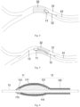
- a proximal portion 11b of the rotating abrasive head 11 has a diameter gradually decreasing along its axis from distal to proximal. Accordingly, the proximal portion 11b of the rotating abrasive head 11 may have a smooth tapered surface, which can facilitate passage through a lesion during retraction. Moreover, the proximal portion 11b of the rotating abrasive head 11 may also be coated on its outer surface with the abrasive layer 111 (see Figs. 2 and 6 ).
- the rotating abrasive head 11 can provide bidirectional atherectomy in both distal, forward and proximal, backward directions.
- the rotating abrasive head 11 gets stuck in a lesion during its forward movement under the action of a pushing force, it can be retracted while abrading the lesion.
- the rotating abrasive head 11 can be prevented from getting stuck in a vascular plaque and being not able to move anymore, further reducing the risk of a surgical procedure.
- the entire outer surface of the rotating abrasive head 11 is coated with the abrasive layer 111.
- an intermediate portion 11c of the rotating abrasive head 11 between the distal portion 11a and the proximal portion 11b is also coated on its outer surface with the abrasive layer 111.
- the intermediate portion 11c may have a constant diameter, hence the intermediate portion 11c has a cylindrical shape. That is, the rotating abrasive head 11 may be cylindrical in the middle and tapered at both ends.
- the intermediate portion 11c may have a diameter, which is equal to maximum diameters of the proximal portion 11b and the distal portion 11a.
- the intermediate portion 11c may have a diameter, which gradually increases and then gradually decreases along its axis from distal to proximal.
- the outer surface of the intermediate portion 11c may be curved, and the rotating abrasive head 11 may be generally spindle-shaped.
- a diameter of the intermediate portion 11c at its distal end may be equal to a maximum diameter of the distal portion 11a at its proximal end, and a diameter of the intermediate portion 11c at its proximal end may be equal to a maximum diameter of the proximal portion 11b at its distal end, as shown in Figs. 1 to 6 .
- the rotating abrasive head 11 may include a base 112, the base 112 may define the aforementioned hollow cavity of the rotating abrasive head 11.
- the abrasive layer 111 may be coated on an outer surface of the base 112.
- the abrasive layer 111 may be composed of abrasive grains, which may be made of one or more abrasive materials.
- the abrasive grains may be fixed to the base 112 by being partially embedded therein.
- a thickness of the abrasive layer 111 may be in the range of 20-120 ⁇ m, such as 20 ⁇ m, 40 ⁇ m, 50 ⁇ m or 100 ⁇ m.
- the thickness of the abrasive layer 111 refers to its thickness above a surface of the base 112. Desirably, the thickness of the abrasive layer 111 is not too large or too small. The larger the thickness of the abrasive layer 111, the larger the static diameter of the rotating abrasive head. An excessively thickness of the abrasive layer 111 is not conducive to atherectomy performance.
- the present invention is not limited to any particular material of the abrasive grains.
- the abrasive grains may be made of one or more suitable abrasive materials.
- the abrasive grains may be made of one or more of diamond, fused silica, titanium nitride, tungsten carbide, silicon carbide, etc.
- the present invention is not limited to any particular material of the base 112.
- the base 112 may be made of one or more suitable materials, such as metallic and non-metallic materials.
- the base 112 may be made of one or more metallic materials such as stainless steel, nickel, etc.
- the material of the base 112 may further include a radiopaque material, for example, one or more of radiopaque materials such as tungsten, platinum, iridium, etc.
- the rotating abrasive head 11 is preferred to have a diameter gradually decreasing along its axis both distally and proximally.
- the gradually distally decreasing diameter of the rotating abrasive head 11 along its axis can facilitate atherectomy by the distal portion 11a in the forward direction.
- the diameter of the distal portion 11a is smaller than that of the intermediate portion 11c, the distal portion 11a of the rotating abrasive head 11 can more easily first come into contact with a lesion in need of atherectomy.
- the gradually proximally decreasing diameter of the rotating abrasive head 11 along its axis enables atherectomy by the proximal portion 11b during its retraction in the backward direction. Moreover, since the diameter of the proximal portion 11b is smaller than that of the intermediate portion 11c, the proximal portion 11b of the rotating abrasive head 11 can more easily first come into contact with a lesion in need of atherectomy during its retraction. Further, a minimum diameter of the distal portion 11a of the rotating abrasive head 11 may be smaller than a minimum diameter of the proximal portion 11b of the rotating abrasive head 11. With this arrangement, the rotating abrasive head 11 is narrowest at its distal end.
- the maximum diameter of the distal portion 11a of the rotating abrasive head 11 may be smaller than that of the proximal portion 11b of the rotating abrasive head 11. This allows the distal portion 11a to have a greater lengthwise extent, which is also conducive to advancement of the rotating abrasive head 11 through a narrow blood vessel and catheter and its arrival at a target vascular lesion.
- the rotating abrasive head 11 may be shaped like a spindle wider in the middle and tapering toward the ends.
- the spindle-shaped rotating abrasive head 11 may have a smooth outer surface and define certain degrees of curvature at the ends.
- the diameter of the distal portion 11a of the rotating abrasive head 11 may be configured based on a diameter of the guide body 13. In one embodiment, the diameter of the distal portion 11a of the rotating abrasive head 11 may be 0.13-0.66 mm.
- the minimum diameter of the distal portion 11a may be configured to be 0.13 mm, 0.2 mm or 0.3 mm, and the maximum diameter thereof may be configured to be 0.66 mm.
- the diameter of the proximal portion 11b of the rotating abrasive head 11 may also be configured based on the diameter of the drive shaft 12. In one embodiment, the diameter of the proximal portion 11b of the rotating abrasive head 11 may be 0.5-1.2 mm.
- the minimum diameter of the proximal portion 11b may be configured to be 0.5 mm, 0.7 mm or 1.0 mm, and the maximum diameter thereof may be configured to be 1.2 mm.
- the intermediate portion 11c of the rotating abrasive head 11 may have a maximum diameter configured based on the diameters of both the guide body 13 and the drive shaft 12.
- the maximum diameter of the intermediate portion 11c of the rotating abrasive head 11 may be 0.66-4.0 mm, such as 0.66 mm, 1.25 mm, 2.0mm or 4.0 mm. It will also be understood that the intermediate portion 11c of the rotating abrasive head 11 should not be narrowly interpreted as being defined absolutely at the middle thereof; rather, it may be defined at any location between the distal portion 11a and the proximal portion 11b.
- the guide body 13 may form part of the rotational atherectomy device 10, the guide body 13 be configured to be inserted through the hollow cavities of both the drive shaft 12 and the rotating abrasive head 11, the guide body 13 protrude out of the distal end of the rotating abrasive head 11.
- the rotating abrasive head 11 and the drive shaft 12 may be rotatable and axially movable relative to the guide body 13 to allow the drive shaft 12 to translate and rotate on the guide body 13.
- the guide body 13 may be provided as a separate component for use in cooperation with the rotational atherectomy device 10.
- the coupling is generally accomplished by inserting the connecting portion 121 of the drive shaft 12 into the hollow cavity of the rotating abrasive head 11.
- the hollow cavity of the rotating abrasive head 11 may consist of distal and proximal hollow cavity sections in communication with each other.
- the distal hollow cavity section may have a diameter matching the diameter of the guide body 13, and the proximal hollow cavity section may have a diameter greater than the diameter of the distal hollow cavity section.
- the connecting portion 121 may be secured to the proximal hollow cavity section.
- distal hollow cavity section is configured for insertion of the guide body 13 therethrough
- proximal hollow cavity section is configured for insertion of the connecting portion 121 of the drive shaft 12 therethrough, with the guide body 13 being in turn inserted through the drive shaft 12.
- Figs. 1 and 2 show an optional embodiment of coupling the drive shaft 12 to the rotating abrasive head 11.
- the hollow cavity of the rotating abrasive head 11 consists of a distal hollow cavity section 113 and a proximal hollow cavity section 114, which communicate with each other. Both the distal cavity section 113 and the proximal cavity section 114 are cylindrical and their center axes coincide with each other.
- the distal hollow cavity section 113 has a diameter matching a diameter of a guidewire, and the proximal hollow cavity section 114 has a diameter matching an overall diameter of the drive shaft 12.
- the drive shaft 12 is a constant-diameter hollow tubular structure, and the connecting portion 121 of the drive shaft 12 is inserted into the proximal hollow cavity section 114 and secured to the proximal hollow cavity section 114, for example, the connecting portion 121 is secured to the proximal hollow cavity section 114 by crimping.
- crimping it is intended to mean that the diameter of the drive shaft 12 may be greater than that of the proximal hollow cavity section 114 and the connecting portion 121 may be secured to the proximal hollow cavity section 114 by being deformed and inserted therein.
- center axes of the distal cavity section 113 and the proximal cavity section 114 both coincide with the center axis of the drive shaft 12.
- the drive shaft 12 may be a varying-diameter hollow tubular structure.
- Fig. 6 shows another optional embodiment of coupling the drive shaft 12 to the rotating abrasive head 11.
- the connecting portion 121 is inserted into the proximal hollow cavity section 114 through a proximal opening of the rotating abrasive head 11.
- the proximal opening has a radial dimension smaller than or equal to the diameter of the proximal end of the connecting portion 121, thereby restricting the drive shaft 12 from moving away from the rotating abrasive head 11. In this way, the drive shaft 12 is prevented from separation from the rotating abrasive head 11 during an atherectomy procedure.
- the connecting portion 121 may be welded, glued or otherwise secured to the proximal hollow cavity section 114.
- the center axes of the distal cavity section 113 and the proximal cavity section 114 both coincide with the center axis of the drive shaft 12.
- the proximal hollow cavity section 114 may have a matching spindle-like shape, and the connecting portion 121 may have a similar spindle-like shape complementary to that of the proximal hollow cavity section 114.
- the diameter of the connecting portion 121 may gradually increase and then gradually decrease along its axis from proximal to distal.
- the rotating abrasive head 11 may be configured as a hollow shell. This allows the rotating abrasive head 11 to have a reduced weight, which can mitigate the influence of a centrifugal force on movement of the rotating abrasive head 11.
- the distal portion 11a and proximal portion 11b of the rotating abrasive head 11 may have the same or different radii of curvature.
- the radius of curvature of the distal portion 11a of the rotating abrasive head 11 may be greater than or equal to that of the proximal portion 11b of the rotating abrasive head 11.
- the radius of curvature of the distal portion 11a of the rotating abrasive head 11 is preferred to be greater than that of the proximal portion 11b of the rotating abrasive head 11 because this allows the distal portion 11a to be less steep and can more easily pass through a lesion.
- the structure of the rotating abrasive head 11 is further explained below with respect to specific embodiments.
- Figs. 1 to 3 show an exemplary embodiment of the rotating abrasive head 11.
- the abrasive layer 111 has an average thickness of 50 ⁇ m, and the abrasive layer 111 is made of diamond abrasive grains.
- the base 112 is made of a combination of stainless steel and nickel, and the rotating abrasive head 11 has a spindle-like shape tapered at both ends.
- the distal portion 11a of the rotating abrasive head 11 defines a minimum diameter, which allows for better atherectomy and drilling into a stenotic portion.
- the radius of curvature of the distal portion 11a of the rotating abrasive head 11 is 4.5 mm, and the radius of curvature of the proximal portion 11b of the rotating abrasive head 11 is 3.5 mm.
- the minimum diameter of the distal portion 11a of the rotating abrasive head 11 is 0.30 mm, and the maximum diameter of the intermediate portion 11c of the rotating abrasive head 11 is 1.25 mm.
- the minimum diameter of the proximal portion 11b of the rotating abrasive head 11 is 0.75 mm.
- the rotating abrasive head 11 coupled to the connecting portion 121 of the drive shaft 12 may be deployed in a blood vessel 31, the entire outer surface of the rotating abrasive head 11 is coated with the abrasive layer 111, the distal portion 11a of the rotating abrasive head 11 has a minimum diameter.
- the abrasive layer 111 on the distal portion 11a of the rotating abrasive head 11 may first come into contact with a stenotic lesion 32 for atherectomy and recanalization. As shown in Fig.
- a rotational atherectomy device 10 may be advanced on the guide body 13 through the stenotic lesion 32 as a result of being pushed distally by an operator.
- a diameter defined by the stenotic lesion 32 may be smaller than a maximum diameter of the rotating abrasive head 11, the rotating abrasive head 11 may get stuck in the stenotic lesion 32 and not be able to be retracted back through the lesion.
- the proximal portion of the rotating abrasive head 11 is also tapered and covered with the abrasive layer 111, it is capable of atherectomy and recanalization while being retracted backward.
- Fig. 6 shows another exemplary embodiment of the rotating abrasive head 11.
- the abrasive layer 111 has an average thickness of 100 ⁇ m
- the base 112 is made of nickel and structured like a shell.
- the abrasive layer 111 is made of diamond abrasive grains
- the rotating abrasive head 11 is shaped like a spindle tapered at both ends.
- the rotating abrasive head 11 defines a minimum diameter at the distal portion 11a, which allows for better atherectomy and drilling into a stenotic portion.
- the radius of curvature of the distal portion 11a of the rotating abrasive head 11 is 3 mm, and the radius of curvature of the proximal portion 11b of the rotating abrasive head 11 is 3 mm.
- the minimum diameter of the rotating abrasive head 11 defined at the distal portion 11a is 0.20 mm, and the maximum diameter of the intermediate portion 11c of the rotating abrasive head 11 is 2.0 mm.
- the minimum diameter of the proximal portion 11b of the rotating abrasive head 11 is 1.0 mm.
- the rotational atherectomy device 10 may be delivered to an in vivo target site through a catheter 41. Additionally, a liquid coolant and/or lubricant (typically saline or other biocompatible liquids) may be supplied to the rotational atherectomy device 10 through a passage in the catheter 41.
- a liquid coolant and/or lubricant typically saline or other biocompatible liquids
- the rotational atherectomy device and apparatus have at least the following advantages:
- the rotating abrasive head when the rotating abrasive head is coated on its entire outer surface with the abrasive layer, it is capable of bidirectional atherectomy. Thus, even when the rotating abrasive head gets stuck in a lesion during its forward movement under the action of a pushing force, it can be retracted while abrading the lesion. As a result, not only more efficient atherectomy can be achieved, the risk of a surgical procedure using the device can be further reduced.
- the rotating abrasive head since the centroid of the structure does not coincide with the center axes of the hollow cavities, as the rotating abrasive head and the drive shaft are spun about the center axes of the hollow cavities, the rotating abrasive head will revolve under the action of a centrifugal force about an axis deviated from the center axes of the hollow cavities.
- the diameter of revolution of the rotating abrasive head can be controlled by adjusting its speed of rotation. For example, the diameter of atherectomy may increase with the speed of rotation beyond the static diameter of the rotating abrasive head.
- the rotating abrasive head is allowed to have a smaller static diameter, and the use of multiple rotating abrasive heads of various static diameters can be avoided, which may require interchanging of these rotating abrasive heads during surgery.
- the diameter of atherectomy that is larger than the static diameter of the rotating abrasive head can facilitate flow of blood, a liquid coolant and/or a liquid lubricant to flow around the rotating abrasive head and reduce the risk of the rotating abrasive head blocking blood flow in a blood vessel.
Landscapes
- Health & Medical Sciences (AREA)
- Surgery (AREA)
- Life Sciences & Earth Sciences (AREA)
- Biomedical Technology (AREA)
- Nuclear Medicine, Radiotherapy & Molecular Imaging (AREA)
- Engineering & Computer Science (AREA)
- Vascular Medicine (AREA)
- Heart & Thoracic Surgery (AREA)
- Medical Informatics (AREA)
- Molecular Biology (AREA)
- Animal Behavior & Ethology (AREA)
- General Health & Medical Sciences (AREA)
- Public Health (AREA)
- Veterinary Medicine (AREA)
- Surgical Instruments (AREA)
Applications Claiming Priority (2)
| Application Number | Priority Date | Filing Date | Title |
|---|---|---|---|
| CN202210615844.1A CN114916997B (zh) | 2022-05-31 | 2022-05-31 | 旋磨装置及旋磨设备 |
| PCT/CN2023/094969 WO2023231791A1 (zh) | 2022-05-31 | 2023-05-18 | 旋磨装置及旋磨设备 |
Publications (2)
| Publication Number | Publication Date |
|---|---|
| EP4497401A1 true EP4497401A1 (de) | 2025-01-29 |
| EP4497401A4 EP4497401A4 (de) | 2025-07-02 |
Family
ID=82813106
Family Applications (1)
| Application Number | Title | Priority Date | Filing Date |
|---|---|---|---|
| EP23814976.9A Pending EP4497401A4 (de) | 2022-05-31 | 2023-05-18 | Rotierende atherektomievorrichtung und rotierende atherektomievorrichtung |
Country Status (4)
| Country | Link |
|---|---|
| US (1) | US20250261964A1 (de) |
| EP (1) | EP4497401A4 (de) |
| CN (1) | CN114916997B (de) |
| WO (1) | WO2023231791A1 (de) |
Families Citing this family (3)
| Publication number | Priority date | Publication date | Assignee | Title |
|---|---|---|---|---|
| CN114916997B (zh) * | 2022-05-31 | 2025-11-04 | 上海微创旋律医疗科技有限公司 | 旋磨装置及旋磨设备 |
| CN115886931B (zh) * | 2022-11-25 | 2025-09-26 | 苏州华融医疗器械有限公司 | 一种骨科医生用的磨钻组件 |
| CN118058796B (zh) * | 2024-01-25 | 2025-09-02 | 明澈生物科技(苏州)有限公司 | 一种用于斑块清除的微机器人及其控制方法 |
Family Cites Families (20)
| Publication number | Priority date | Publication date | Assignee | Title |
|---|---|---|---|---|
| US5360432A (en) * | 1992-10-16 | 1994-11-01 | Shturman Cardiology Systems, Inc. | Abrasive drive shaft device for directional rotational atherectomy |
| US5681336A (en) * | 1995-09-07 | 1997-10-28 | Boston Scientific Corporation | Therapeutic device for treating vien graft lesions |
| US6217595B1 (en) * | 1996-11-18 | 2001-04-17 | Shturman Cardiology Systems, Inc. | Rotational atherectomy device |
| US6132444A (en) * | 1997-08-14 | 2000-10-17 | Shturman Cardiology Systems, Inc. | Eccentric drive shaft for atherectomy device and method for manufacture |
| US7507245B2 (en) * | 2001-10-19 | 2009-03-24 | Cardiovascular Systems, Inc. | Rotational angioplasty device with abrasive crown |
| GB2426458A (en) * | 2005-05-26 | 2006-11-29 | Leonid Shturman | Atherectomy device |
| US8597313B2 (en) * | 2007-06-11 | 2013-12-03 | Cardiovascular Systems, Inc. | Eccentric abrading head for high-speed rotational atherectomy devices |
| US8795303B2 (en) * | 2009-02-02 | 2014-08-05 | Cardiovascular Systems, Inc. | Multi-material abrading head for atherectomy devices having laterally displaced center of mass |
| US20120046600A1 (en) * | 2010-02-25 | 2012-02-23 | Cardiovascular Systems, Inc. | High-speed rotational atherectomy system, device and method for localized application of therapeutic agents to a biological conduit |
| DK2744424T3 (en) * | 2011-08-17 | 2018-01-22 | Samuel Shiber | Adaptively rotating catheter to open clogged vessels in the body |
| US9289230B2 (en) * | 2012-09-17 | 2016-03-22 | Cardiovascular Systems, Inc. | Rotational atherectomy device with a system of eccentric abrading heads |
| EP2967635B1 (de) * | 2013-03-12 | 2017-06-28 | Boston Scientific Scimed, Inc. | Schwingungs- und trägheitsverstärkte atherektomie |
| US9468457B2 (en) * | 2013-09-30 | 2016-10-18 | Cardiovascular Systems, Inc. | Atherectomy device with eccentric crown |
| US10271869B2 (en) * | 2014-03-01 | 2019-04-30 | Rex Medical, L.P. | Atherectomy device |
| US10405878B2 (en) * | 2014-07-25 | 2019-09-10 | Boston Scientific Scimed, Inc. | Rotatable medical device |
| US10405879B2 (en) * | 2014-12-04 | 2019-09-10 | Boston Scientific Scimed, Inc. | Rotatable medical device |
| CN111012448A (zh) * | 2019-08-20 | 2020-04-17 | 上海微创医疗器械(集团)有限公司 | 旋磨装置 |
| CN114098903B (zh) * | 2021-12-14 | 2025-04-18 | 上海融脉医疗科技有限公司 | 一种轨道式机械血栓抽吸导管 |
| CN217645302U (zh) * | 2022-05-31 | 2022-10-25 | 上海微创旋律医疗科技有限公司 | 旋磨装置及旋磨设备 |
| CN114916997B (zh) * | 2022-05-31 | 2025-11-04 | 上海微创旋律医疗科技有限公司 | 旋磨装置及旋磨设备 |
-
2022
- 2022-05-31 CN CN202210615844.1A patent/CN114916997B/zh active Active
-
2023
- 2023-05-18 US US18/860,270 patent/US20250261964A1/en active Pending
- 2023-05-18 WO PCT/CN2023/094969 patent/WO2023231791A1/zh not_active Ceased
- 2023-05-18 EP EP23814976.9A patent/EP4497401A4/de active Pending
Also Published As
| Publication number | Publication date |
|---|---|
| CN114916997A (zh) | 2022-08-19 |
| US20250261964A1 (en) | 2025-08-21 |
| EP4497401A4 (de) | 2025-07-02 |
| WO2023231791A1 (zh) | 2023-12-07 |
| CN114916997B (zh) | 2025-11-04 |
Similar Documents
| Publication | Publication Date | Title |
|---|---|---|
| EP4497401A1 (de) | Rotierende atherektomievorrichtung und rotierende atherektomievorrichtung | |
| EP2429424B1 (de) | Rotations-atherektomievorrichtung zur verbesserung der schleifwirsamkeit | |
| CA2718914C (en) | Method and apparatus for increasing rotational amplitude of abrasive element on high-speed rotational atherectomy device | |
| US8597313B2 (en) | Eccentric abrading head for high-speed rotational atherectomy devices | |
| EP2488113B1 (de) | Exzentrischer schleif- und schneidekopf für rotierende hochgeschwindigkeits-atherektomievorrichtungen | |
| EP2895088B1 (de) | Rotierende atherektomievorrichtung mit einem system aus exzentrischen schleifköpfen | |
| EP2303149B1 (de) | Ekzentrischer abrasions- und schneidekopf für rotierende hochgeschwindigkeits-atherektomie-vorrichtungen | |
| US10517631B2 (en) | Rotational atherectomy device with a system of eccentric abrading heads | |
| EP4005513B1 (de) | Rotationsschleifvorrichtung und medizinisches gerät mit der rotationsschleifvorrichtung | |
| CN102325502A (zh) | 作为旋切术一部分的研磨头和改善研磨效能的方法 | |
| CN102300510A (zh) | 用于具有横向位移的质心的切除术设备的多材料研磨头 | |
| CN108882947B (zh) | 具有偏心研磨头系统的旋切装置 | |
| CN118302119A (zh) | 具有柔性远侧尖端的组织移除导管 | |
| HK1164089B (en) | Rotational atherectomy segmented abrading head | |
| HK1158917B (en) | Method and apparatus for increasing rotational amplitude of abrasive element on high-speed rotational atherectomy device |
Legal Events
| Date | Code | Title | Description |
|---|---|---|---|
| STAA | Information on the status of an ep patent application or granted ep patent |
Free format text: STATUS: THE INTERNATIONAL PUBLICATION HAS BEEN MADE |
|
| PUAI | Public reference made under article 153(3) epc to a published international application that has entered the european phase |
Free format text: ORIGINAL CODE: 0009012 |
|
| STAA | Information on the status of an ep patent application or granted ep patent |
Free format text: STATUS: REQUEST FOR EXAMINATION WAS MADE |
|
| 17P | Request for examination filed |
Effective date: 20241021 |
|
| AK | Designated contracting states |
Kind code of ref document: A1 Designated state(s): AL AT BE BG CH CY CZ DE DK EE ES FI FR GB GR HR HU IE IS IT LI LT LU LV MC ME MK MT NL NO PL PT RO RS SE SI SK SM TR |
|
| A4 | Supplementary search report drawn up and despatched |
Effective date: 20250604 |
|
| RIC1 | Information provided on ipc code assigned before grant |
Ipc: A61B 17/3207 20060101AFI20250528BHEP |
|
| DAV | Request for validation of the european patent (deleted) | ||
| DAX | Request for extension of the european patent (deleted) |