EP4497397A1 - Okkluder - Google Patents
Okkluder Download PDFInfo
- Publication number
- EP4497397A1 EP4497397A1 EP23778536.5A EP23778536A EP4497397A1 EP 4497397 A1 EP4497397 A1 EP 4497397A1 EP 23778536 A EP23778536 A EP 23778536A EP 4497397 A1 EP4497397 A1 EP 4497397A1
- Authority
- EP
- European Patent Office
- Prior art keywords
- proximal
- distal
- disc
- cambered surface
- bending area
- Prior art date
- Legal status (The legal status is an assumption and is not a legal conclusion. Google has not performed a legal analysis and makes no representation as to the accuracy of the status listed.)
- Pending
Links
Images


Classifications
-
- A—HUMAN NECESSITIES
- A61—MEDICAL OR VETERINARY SCIENCE; HYGIENE
- A61B—DIAGNOSIS; SURGERY; IDENTIFICATION
- A61B17/00—Surgical instruments, devices or methods
- A61B17/0057—Implements for plugging an opening in the wall of a hollow or tubular organ, e.g. for sealing a vessel puncture or closing a cardiac septal defect
-
- A—HUMAN NECESSITIES
- A61—MEDICAL OR VETERINARY SCIENCE; HYGIENE
- A61B—DIAGNOSIS; SURGERY; IDENTIFICATION
- A61B17/00—Surgical instruments, devices or methods
- A61B2017/00004—(bio)absorbable, (bio)resorbable or resorptive
-
- A—HUMAN NECESSITIES
- A61—MEDICAL OR VETERINARY SCIENCE; HYGIENE
- A61B—DIAGNOSIS; SURGERY; IDENTIFICATION
- A61B17/00—Surgical instruments, devices or methods
- A61B17/0057—Implements for plugging an opening in the wall of a hollow or tubular organ, e.g. for sealing a vessel puncture or closing a cardiac septal defect
- A61B2017/00575—Implements for plugging an opening in the wall of a hollow or tubular organ, e.g. for sealing a vessel puncture or closing a cardiac septal defect for closure at remote site, e.g. closing atrial septum defects
- A61B2017/00588—Rigid or stiff implements, e.g. made of several rigid parts linked by hinges
-
- A—HUMAN NECESSITIES
- A61—MEDICAL OR VETERINARY SCIENCE; HYGIENE
- A61B—DIAGNOSIS; SURGERY; IDENTIFICATION
- A61B17/00—Surgical instruments, devices or methods
- A61B17/0057—Implements for plugging an opening in the wall of a hollow or tubular organ, e.g. for sealing a vessel puncture or closing a cardiac septal defect
- A61B2017/00575—Implements for plugging an opening in the wall of a hollow or tubular organ, e.g. for sealing a vessel puncture or closing a cardiac septal defect for closure at remote site, e.g. closing atrial septum defects
- A61B2017/00592—Elastic or resilient implements
-
- A—HUMAN NECESSITIES
- A61—MEDICAL OR VETERINARY SCIENCE; HYGIENE
- A61B—DIAGNOSIS; SURGERY; IDENTIFICATION
- A61B17/00—Surgical instruments, devices or methods
- A61B17/0057—Implements for plugging an opening in the wall of a hollow or tubular organ, e.g. for sealing a vessel puncture or closing a cardiac septal defect
- A61B2017/00575—Implements for plugging an opening in the wall of a hollow or tubular organ, e.g. for sealing a vessel puncture or closing a cardiac septal defect for closure at remote site, e.g. closing atrial septum defects
- A61B2017/00597—Implements comprising a membrane
-
- A—HUMAN NECESSITIES
- A61—MEDICAL OR VETERINARY SCIENCE; HYGIENE
- A61B—DIAGNOSIS; SURGERY; IDENTIFICATION
- A61B17/00—Surgical instruments, devices or methods
- A61B17/0057—Implements for plugging an opening in the wall of a hollow or tubular organ, e.g. for sealing a vessel puncture or closing a cardiac septal defect
- A61B2017/00575—Implements for plugging an opening in the wall of a hollow or tubular organ, e.g. for sealing a vessel puncture or closing a cardiac septal defect for closure at remote site, e.g. closing atrial septum defects
- A61B2017/00606—Implements H-shaped in cross-section, i.e. with occluders on both sides of the opening
-
- A—HUMAN NECESSITIES
- A61—MEDICAL OR VETERINARY SCIENCE; HYGIENE
- A61B—DIAGNOSIS; SURGERY; IDENTIFICATION
- A61B17/00—Surgical instruments, devices or methods
- A61B17/0057—Implements for plugging an opening in the wall of a hollow or tubular organ, e.g. for sealing a vessel puncture or closing a cardiac septal defect
- A61B2017/00575—Implements for plugging an opening in the wall of a hollow or tubular organ, e.g. for sealing a vessel puncture or closing a cardiac septal defect for closure at remote site, e.g. closing atrial septum defects
- A61B2017/0061—Implements located only on one side of the opening
-
- A—HUMAN NECESSITIES
- A61—MEDICAL OR VETERINARY SCIENCE; HYGIENE
- A61B—DIAGNOSIS; SURGERY; IDENTIFICATION
- A61B17/00—Surgical instruments, devices or methods
- A61B17/0057—Implements for plugging an opening in the wall of a hollow or tubular organ, e.g. for sealing a vessel puncture or closing a cardiac septal defect
- A61B2017/00575—Implements for plugging an opening in the wall of a hollow or tubular organ, e.g. for sealing a vessel puncture or closing a cardiac septal defect for closure at remote site, e.g. closing atrial septum defects
- A61B2017/00632—Occluding a cavity, i.e. closing a blind opening
-
- A—HUMAN NECESSITIES
- A61—MEDICAL OR VETERINARY SCIENCE; HYGIENE
- A61B—DIAGNOSIS; SURGERY; IDENTIFICATION
- A61B17/00—Surgical instruments, devices or methods
- A61B17/0057—Implements for plugging an opening in the wall of a hollow or tubular organ, e.g. for sealing a vessel puncture or closing a cardiac septal defect
- A61B2017/00646—Type of implements
- A61B2017/00659—Type of implements located only on one side of the opening
Definitions
- the present invention relates to the technical field of medical devices, and particularly to an occluder.
- the occluders used for the interventional therapy on the market are made of nickel-titanium alloy, which has good shape memory properties.
- the nickel-titanium alloy material is non-degradable after being implanted in the human body and carries the risk of metal ion leaching.
- the biodegradable occluder is a new type of occluder product that can effectively occlude the cardiac defect while being biodegradable within a suitable time.
- the degradation products can be completely metabolized by the human body, leaving no residual materials after the cardiac defect has been repaired. Therefore, the degradable occluder is the development trend.
- the mechanical properties of degradable materials cannot reach those of the metal materials, the compliance and recovery of the prepared occluder are poor.
- An occluder including a distal disc, a waist portion and a proximal disc formed in sequence;
- the proximal disc includes a proximal disc surface, a proximal bending area bent toward the distal disc is formed at a circumference of the proximal disc surface, and wherein the proximal bending area surrounds an edge of the distal disc, and a stabilizing wire is further threaded through a free end of the proximal bending area and able to tighten the free end of the proximal bending area towards the waist portion.
- a diameter of the proximal disc is greater than a diameter of the distal disc
- the distal disc includes a distal disc surface, a distal bending area arranged opposite to the proximal bending area is formed at a circumference of the distal disc surface, and a free end of the distal bending area extends into the proximal bending area.
- the proximal bending area includes a proximal outer cambered surface extending from the circumference of the proximal disc surface, a distance between an inner end of the proximal outer cambered surface and an axis of the waist portion is less than a distance between an outer end of the proximal outer cambered surface and the axis of the waist portion, and the stabilizing wire is threaded through the outer end of the proximal outer cambered surface.
- the proximal bending area bulges away from the distal disc and includes a proximal inner cambered surface, a proximal bending arc and the proximal outer cambered surface connected in sequence, an inner end of the proximal inner cambered surface is connected to the proximal disc surface, and the stabilizing wire is threaded through the outer end of the proximal outer cambered surface, the distance between the inner end of the proximal outer cambered surface and the axis of the waist portion is less than the distance between the outer end of the proximal outer cambered surface and the axis of the waist portion.
- a supplementary angle ⁇ of an included angle between the proximal outer cambered surface and the proximal disc surface is in a range of greater than 90 degrees and less than 170 degrees.
- an arc of the proximal bending arc is less than or equal to 90 degrees
- the supplementary angle ⁇ of the included angle between the proximal outer cambered surface and the proximal disc surface is in a range of greater than 90 degrees and less than 160 degrees.
- a projected length of the proximal outer cambered surface in an axial direction of the proximal disc surface is greater than or equal to 1 mm, and a projected length of the proximal outer cambered surface in a radial direction of the proximal disc surface is less than a half of the diameter of the proximal disc.
- the distal bending area includes a distal outer cambered surface extending from the circumference of the distal disc surface, a distance between an inner end of the distal outer cambered surface and the axis of the waist portion is less than the distance between the outer end of the proximal outer cambered surface and the axis of the waist portion, and the stabilizing wire is threaded through the outer end of the distal outer cambered surface.
- the distal bending area is bent towards the proximal disc and protrudes, including a distal inner cambered surface, a distal bending arc and the distal outer cambered surface extending from the circumference of the distal disc surface in sequence, a distance between an inner end of the distal outer cambered surface and the axis of the waist portion is greater than a distance between an outer end of the distal outer cambered surface and the axis of the waist portion, and the free end of the distal outer cambered surface extends into the proximal bending area.
- a supplementary angle ⁇ of an included angle between the distal outer cambered surface and the distal disc surface is in a range of greater than 90 degrees and less than 170 degrees.
- an arc of the distal bending arc is less than or equal to 90 degrees, and the included angle between the distal outer cambered surface and an extension surface of the distal disc surface is in a range of greater than 90 degrees and less than 160 degrees; a projected length of the distal outer cambered surface in an axial direction of the distal disc surface is greater than or equal to 1 mm, and a projected length of the distal outer cambered surface in a radial direction of the distal disc surface is less than a half of the diameter of the distal disc.
- a stabilizing wire is also threaded through the free end of the distal bending area, and the stabilizing wire includes one or more loops.
- an inner wall of the distal disc, an inner wall of the proximal disc, and a position between the proximal disc and the distal disc are covered with flow blocking membranes.
- the proximal disc, the waist portion, and the distal disc are all made of degradable wires, and the occluder is further provided with a developing mark.
- the developing mark is a platinum wire or a platinum ring.
- the proximal disc is provided with two regions, i.e., the proximal disc surface and the proximal bending area.
- the proximal disc surface relatively forms a subsidence area
- the proximal bending area is provided as a part mainly used for providing a locking force so that the recovering effect of the shape of the proximal disc surface may be increased.
- the bending area formed by the proximal bending area may increase a fitting length of the proximal disc to a tissue surface, enhance the fitting and occluding effect, promote rapid endothelialization, and avoid residual shunts.
- the stabilizing wire is provided so that the proximal bending area may provide a centripetal force to the septal tissue, ensuring that the occluder can stably maintain the design shape and size for a long time after implantation, thereby always fitting to the interatrial septum stably. Meanwhile, the buckling and surrounding pattern of the proximal bending area of the proximal disc to the distal disc may further ensure that the occluder can clamp and fit the septal tissue after implantation.
- orientation or positional relationships indicated by the terms “center”, “upper”, “lower”, “left”, “right”, “vertical”, “horizontal”, “inner”, “outer”, and the like are based on the orientation or positional relationships shown in the drawings, and are intended only to facilitate and simplify the description of the present invention, and are not intended to indicate or imply that the apparatus or element referred to must have a particular orientation, constructed and operated in a particular orientation, and therefore are not to be construed as limitations of the present invention.
- the terms “first”, “second”, and “third” are used for descriptive purposes only and are not to be construed as indicating or implying relative importance.
- the occluder is of an integrally formed mesh structure, including a proximal disc surface, a waist portion, and a distal disc surface. After implantation, the waist portion passes through the tissue septum, and the proximal disc surface and the distal disc surface are arranged at two sides of the tissue septum for occluding the defect.
- the proximal disc surface and/or the distal disc surface are easily deformed.
- the proximal disc surface and the distal disc surface cannot fit well to the left and right sides of the cardiac septal defect position, resulting in a poor occluding effect and even causing a risk of residual blood shunts.
- the present application provides an occluder, including a distal disc, a waist portion, and a proximal disc.
- the proximal disc includes a proximal disc surface.
- a proximal bending area is formed at a circumference of the proximal disc surface and partially or completely bent towards the distal disc.
- the proximal bending area surrounds an edge of the distal disc, and a stabilizing wire is further threaded through a free end of the proximal bending area and able to tighten the free end of the proximal bending area towards the waist portion.
- the proximal disc of the occluder of the present application has the proximal bending area. Based on the provision of the proximal bending area, after the occluder is implanted in the body, the proximal bending area of the proximal disc can surround the distal disc, and the proximal bending area is bent towards the distal disc. Therefore, the free end of the proximal bending area, i.e., the edge of the proximal bending area, forms a closure with an opening pointing towards the distal disc.
- One or more loops of stabilizing wire that may be retracted are threaded through the free end (i.e., closure) of the proximal bending area. Therefore, when the stabilizing wire locks the proximal disc surface, a centripetal force in the bending area of the proximal disc surface may be enhanced, and a buckling force of the proximal disc surface towards the waist portion may be enhanced.
- the proximal disc is provided with two regions, i.e., the proximal disc surface and the proximal bending area.
- the proximal disc surface relatively forms a subsidence area
- the proximal bending area is provided as a part mainly used for providing a locking force so that the recovering effect of the shape of the proximal disc surface may be increased.
- the bending area formed by the proximal bending area may increase a fitting length of the proximal disc to a tissue surface, enhance the fitting and occluding effect, promote rapid endothelialization, and avoid residual shunts.
- the stabilizing wire is provided so that the proximal bending area may provide a centripetal force to the septal tissue, ensuring that the occluder can stably maintain the design shape and size for a long time after implantation, thereby always fitting to the interatrial septum stably. Meanwhile, the buckling and surrounding pattern of the proximal bending area of the proximal disc to the distal disc may further ensure that the occluder can clamp and fit the septal tissue after implantation.
- a diameter of the proximal disc is greater than a diameter of the distal disc; the distal disc includes a distal disc surface, and a distal bending area is formed at a circumference of the distal disc surface; the distal bending area is provided opposite to the proximal bending area, and a free end of the distal bending area (i.e., an outer cambered surface of the distal bending area) extends into the proximal bending area.
- the distal disc is also provided with two regions, i.e., the distal disc surface and the distal bending area.
- the distal bending area is provided opposite to the proximal bending area, and the free end of the distal bending area extends into the proximal bending area so as to form a pattern in which the proximal disc surrounds the distal disc, and the proximal disc and the distal disc are buckled to each other.
- the distal bending area and the proximal bending area of the occluder are both buckled towards the waist portion in a locked state of the stabilizing wires.
- the buckling and surrounding pattern of the proximal disc surface and the distal disc surface ensures that the occluder can maximally clamp and fit the atrial septal tissue of the heart after implantation.
- the proximal bending area includes a proximal outer cambered surface extending from the circumference of the proximal disc surface; a distance between an inner end of the proximal outer cambered surface and an axis of the waist portion is less than a distance between an outer end of the proximal outer cambered surface and the axis of the waist portion; the stabilizing wire is threaded through the outer end of the proximal outer cambered surface.
- a longitudinal profile of the proximal bending area is generally in the form of a ramp having the free end extending away from the waist portion.
- the ramp can generate a centripetal force on the proximal disc to tighten towards the waist portion, thereby enhancing the buckling force of the proximal disc surface towards the waist portion and enhancing the rebound effect of the proximal disc surface.
- the proximal bending area bulges away from the distal disc and includes a proximal inner cambered surface, a proximal bending arc, and the proximal outer cambered surface which are connected in sequence; an inner end of the proximal inner cambered surface is connected to the proximal disc surface, and the stabilizing wire is threaded through the outer end of the proximal outer cambered surface; the distance between the inner end of the proximal outer cambered surface and the axis of the waist portion is less than the distance between the outer end of the proximal outer cambered surface and the axis of the waist portion.
- the proximal inner cambered surface, the proximal bending arc, and the proximal outer cambered surface are connected in sequence from inside to outside.
- the longitudinal profile of the proximal bending area is generally "V"-shaped, and the free end of the proximal outer cambered surface extends obliquely outward away from the waist portion. That is, the proximal outer cambered surface forms a ramp with respect to the proximal disc surface.
- the ramp can generate a centripetal force on the proximal disc to tighten towards the waist portion, thereby enhancing the buckling force of the proximal disc surface towards the waist portion and enhancing the rebound effect of the proximal disc surface.
- the proximal inner cambered surface is provided so that a bending arc is formed between the proximal inner cambered surface and the proximal outer cambered surface, thereby increasing the fitting length of the proximal disc to the tissue surface, and further enhancing the fitting and occluding effect.
- a supplementary angle ⁇ of an included angle between the proximal outer cambered surface and the proximal disc surface is in a range of greater than 90 degrees and less than 170 degrees.
- the supplementary angle ⁇ of the included angle between the proximal outer cambered surface and the proximal disc surface is in a range of greater than 90 degrees and less than 150 degrees.
- an arc of the proximal bending arc is less than or equal to 90 degrees
- the supplementary angle ⁇ of the included angle between the proximal outer cambered surface and the proximal disc surface is in a range of greater than 90 degrees and less than 120 degrees.
- the supplementary angle ⁇ of the included angle between the proximal outer cambered surface and the proximal disc surface is in the range of greater than 90 degrees and less than 170 degrees, the clamping and buckling effect of the disc surface may be ensured.
- the supplementary angle ⁇ is less than 90 degrees or greater than 170 degrees, the centripetal force cannot be generated or the centripetal force is too small, and the clamping and buckling effect is poor.
- a projected length of the proximal outer cambered surface in an axial direction of the proximal disc surface is greater than or equal to 1 mm, and a projected length of the proximal outer cambered surface in a radial direction of the proximal disc surface is less than a half of the diameter of the proximal disc.
- the reason for limiting the projected length of the proximal outer cambered surface with respect to the axial direction of the proximal disc surface and the projected length of the proximal outer cambered surface with respect to the radial direction of the proximal disc surface is that the applicant has found through several inventive studies that if the projected length of the proximal outer cambered surface in the radial direction of the proximal disc surface has a range of greater than a half of the diameter of the proximal disc, the disc surface will be easily flanged and unable to recover. If the projected length of the proximal outer cambered surface in the axial direction of the proximal disc surface is too short, the disc surface tends to be flat, and the clamping effect is poor.
- the distal bending area includes a distal outer cambered surface extending from the circumference of the distal disc surface; a distance between an inner end of the distal outer cambered surface and the axis of the waist portion is less than the distance between the outer end of the proximal outer cambered surface and the axis of the waist portion; the stabilizing wire is threaded through the outer end of the distal outer cambered surface.
- the distal bending area is bent towards the proximal disc and protrudes, including a distal inner cambered surface, a distal bending arc, and the distal outer cambered surface which extend from the circumference of the distal disc surface in sequence; an inner end of the distal inner cambered surface is connected to the distal disc surface; a distance between an inner end of the distal outer cambered surface and the axis of the waist portion is greater than a distance between an outer end of the distal outer cambered surface and the axis of the waist portion; the free end of the distal outer cambered surface extends into the proximal bending area.
- a structure of the distal bending area is the same as that of the proximal bending area, thereby further enhancing the occluding effect of the occluder.
- a supplementary angle ⁇ of an included angle between the distal outer cambered surface and the distal disc surface is in a range of greater than 90 degrees and less than 170 degrees.
- the supplementary angle ⁇ of the included angle between the distal outer cambered surface and the distal disc surface is in a range of greater than 90 degrees and less than 150 degrees.
- an arc of the distal bending arc is less than or equal to 90 degrees, and the included angle between the distal outer cambered surface and an extension surface of the distal disc surface is in a range of greater than 90 degrees and less than 120 degrees.
- a projected length of the distal outer cambered surface in an axial direction of the distal disc surface is greater than or equal to 1 mm, and a projected length of the distal outer cambered surface in a radial direction of the distal disc surface is in a range of less than a half of the diameter of the distal disc.
- a stabilizing wire is also threaded through the free end of the distal bending area, and the stabilizing wire includes one or more loops.
- the stabilizing wires are threaded through the outer end of the proximal outer cambered surface and the outer end of the distal outer cambered surface.
- a stabilizing wire may also be provided at the edge of the distal bending area. The stabilizing wire here serves to tighten the distal bending area so that the distal disc has a locking force towards the waist portion so as to enhance the fitting of the distal disc to the tissue surface.
- the stabilizing wire may also partially adjust the size of the occluder and adjust the size and shape of the disc surface of the occluder by tightening or loosening and then fixing and knotting, thereby adapting to the atrial septa with different sizes and shapes.
- the stabilizing wire is woven up and down along woven meshes at the edge of the proximal bending area or the distal bending area, with at least one mesh spaced apart.
- an inner wall of the distal disc, an inner wall of the proximal disc, and a position between the proximal disc and the distal disc are covered with flow blocking membranes.
- the flow blocking effect of the occluder may be enhanced by adding the flow blocking membranes on the proximal disc surface, the distal disc surface, and the waist portion of the occluder.
- the proximal disc, the waist portion, and the distal disc are all made of degradable wires, and the occluder is further provided with a developing mark.
- the developing mark is a platinum wire or a platinum ring.
- the occluder is made of a degradable material so that it is flexible and easy to deform and fit while avoiding wear. The developing mark is provided so that an operator may clearly determine whether the occluder is locked when occluding in the surgical imaging process so as to perform a visual operation, thereby increasing the efficiency of the surgery.
- the proximal end is defined as an end close to the operator during the surgical operation
- the distal end is defined as an end away from the operator during the surgical operation
- the orientations of FIGS. 1-7 are identical in the present application.
- the inner and outer sides are referenced to the waist portion, a side close to the waist portion in the radial direction is defined as the inner side, and a side away from the waist portion in the radial direction is defined as the outer side.
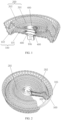
- this embodiment provides an occluder made of a degradable material, including a framework and flow blocking membranes 400.
- the framework is a closed mesh basket woven from a single degradable wire and is flexible and easy to deform and fit.
- the closed mesh basket is heat-shaped into a structure of two discs and a waist through a mould, specifically including a proximal disc 100, a distal disc 200, and a waist portion 300 connecting the proximal disc 100 and the distal disc 200.
- a proximal disc 100, a distal disc 200, and a waist portion 300 connecting the proximal disc 100 and the distal disc 200 Each of an inner wall of the proximal disc 100, an inner wall of the distal disc 200, and a position between the proximal disc 100 and the distal disc 200 is covered with at least one layer of flow blocking membrane 400, and the material of the flow blocking membrane 400 may be selected as a degradable material.
- the degradable materials involved may include amorphous polylactic acid, levorotatory polylactic acid, dextrorotatory polylactic acid, polydioxanone, polycaprolactone, polyglycolic acid, or a polylactic acid-glycolic acid copolymer.
- amorphous polylactic acid levorotatory polylactic acid, dextrorotatory polylactic acid, polydioxanone, polycaprolactone, polyglycolic acid, or a polylactic acid-glycolic acid copolymer.
- one or more blends of polydioxanone, polycaprolactone, polyglycolic acid, the polylactic acid-glycolic acid copolymer or amorphous polylactic acid, levorotatory polylactic acid, and dextrorotatory polylactic acid are preferred.
- the structure of the flow blocking membrane 400 may be a spunlace non-woven fabric, a needle-punched non-woven fabric, a spun-bonded non-woven fabric, a heat-bonded non-woven fabric, a wet-process non-woven fabric, a woven fabric, or an electrostatic spinning fiber membrane.
- the number of layers of the flow blocking membrane 400 may be 2-6 layers, the flow blocking membrane 400 is sutured and fixed in the framework of the occluder through a suture, and multiple layers of the flow blocking membrane 400 may increase the occluding effect.
- a developing mark (not shown in the figures) may also be sewn on the flow blocking membrane 400, and the developing mark may be a platinum wire or a platinum ring.
- a closure of the closed mesh basket is usually located in the center of the proximal disc 100, and a fixing rivet 106 is provided at the closure of the closed mesh basket. The fixing rivet 106 is connected to an external delivery apparatus to facilitate implantation of the occluder in the patient.
- a diameter of the proximal disc 100 is greater than or equal to a diameter of the distal disc 200.
- the proximal disc 100 includes a proximal disc surface 101 and a proximal bending area 102, and an edge of the proximal bending area 102 is higher than an edge of the distal disc 200, forming a surrounding pattern in which the proximal disc 100 surrounds the distal disc 200.
- the proximal bending area 102 extends from a circumference of the proximal disc surface 101, and it is partially or completely bent towards the distal disc 200 and protrudes. It can be understood that the proximal disc 100 includes a subsidence area and a bending area.
- the proximal disc surface 101 constitutes the subsidence area with a subsidence depth of 0.5-3 mm, and the subsidence area may increase the recovering effect of the shape of the proximal disc 100.
- the proximal bending area 102 constitutes the bending area, and the bending area may extend the length of the proximal bending area 102 and increase a fitting length of the proximal disc 100 to a tissue surface, thereby enhancing the fitting and occluding effect. Referring to FIGS.
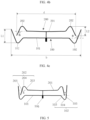
- the proximal bending area 102 includes a proximal inner cambered surface 103, a proximal bending arc 104, and a proximal outer cambered surface 105 which extend from the edge of the proximal disc surface 101 in sequence.
- the proximal bending arc 104 protrudes from the proximal disc surface 101 in a direction away from the waist portion 300, and an arc of the proximal bending arc 104 is 30 degrees to 120 degrees.
- the proximal inner cambered surface 103 and the proximal outer cambered surface 105 each form a ramp with respect to the proximal disc surface 101.
- a distance between an inner end 1051 of the proximal outer cambered surface 105 and an axis of the waist portion 300 is less than a distance between an outer end 1052 of the proximal outer cambered surface 105 and the axis of the waist portion 300. That is, a free end of the proximal outer cambered surface 105 is diverged outwards with respect to the waist portion 300.
- a supplementary angle ⁇ of an included angle between the proximal outer cambered surface 105 and the proximal disc surface 101 is in a range of greater than 90 degrees and less than 170 degrees.
- the supplementary angle ⁇ of the included angle between the proximal outer cambered surface 105 and the proximal disc surface 101 is in a range of greater than 90 degrees and less than 150 degrees.
- a projected length L1 of the proximal outer cambered surface 105 in an axial direction of the proximal disc surface 101 is greater than or equal to 1 mm, and a projected length of the proximal outer cambered surface in a radial direction of the proximal disc surface 101 is less than a half of a diameter b of the proximal disc 100.
- the proximal inner cambered surface 103 includes an inner end 1031 of the proximal inner cambered surface and an outer end 1032 of the proximal inner cambered surface.
- the proximal outer cambered surface 105 includes the inner end 1051 of the proximal outer cambered surface and the outer end 1052 of the proximal outer cambered surface.
- the proximal inner cambered surface 103, the proximal bending arc 104, and the proximal outer cambered surface 105 are connected in sequence from inside to outside.
- the inner end 1031 of the proximal inner cambered surface is connected to the proximal disc surface 101
- the outer end 1032 of the proximal inner cambered surface is connected to one end of the proximal bending arc 104
- the other end of the proximal bending arc 104 is connected to the inner end 1051 of the proximal outer cambered surface
- the outer end 1052 of the proximal outer cambered surface is at an outer edge of the proximal disc 200.
- proximal inner cambered surface 103 extends gradually from inside to outside in a direction away from the inner disc surface 201 (i.e., extends proximally in an inside to outside direction), and the proximal outer cambered surface 105 extends gradually from inside to outside in a direction close to the distal disc surface 201 (i.e., extends distally in an inside to outside direction).
- the distal inner cambered surface 203 includes an inner end 2031 of the distal inner cambered surface and an outer end 2032 of the distal inner cambered surface
- the distal outer cambered surface 205 includes an inner end 2051 of the distal outer cambered surface and an outer end 2052 of the distal outer cambered surface.
- the distal inner cambered surface 203, a distal bending arc 204, and the distal outer cambered surface 205 are connected in sequence from inside to outside.
- the inner end 2031 of the distal inner cambered surface is connected to the distal disc surface 201
- the outer end 2032 of the distal inner cambered surface is connected to one end of the distal bending arc 204
- the other end of the distal bending arc 204 is connected to the inner end 2051 of the distal outer cambered surface
- the outer end 2052 of the distal outer cambered surface is at an outer edge of the distal disc 200.
- distal inner cambered surface 203 extends gradually from inside to outside in a direction away from the proximal disc surface 101 (i.e., extends distally in an inside to outside direction)
- distal outer cambered surface 205 extends gradually from inside to outside in a direction close to the proximal disc surface 101 (i.e., extends proximally in an inside to outside direction).
- FIGS. 4a, 4b , and 4c are the same occluder, and FIGS. 4a, 4b , and 4c are provided for ease of reading and understanding.
- a stabilizing wire 500 is threaded through the outer end of the proximal outer cambered surface 105, and the stabilizing wire 500 includes one or more loops.
- the stabilizing wire 500 is tightened so that the diameter of the proximal disc 101 is reduced, the arc of the proximal bending arc 104 is reduced, and the supplementary angle ⁇ of the included angle between the proximal outer cambered surface 105 and the proximal disc surface 101 is reduced to 90-120°.
- the stabilizing wire 500 locks the proximal disc 101, the centripetal force of the proximal outer cambered surface 105 is enhanced, and the buckling force of the proximal disc 100 towards the waist portion 300 is enhanced so that the proximal disc 100 is more fit to the tissue surface, and the rebound effect of the proximal disc 100 is enhanced.
- the stabilizing wire 500 may also partially adjust the size of the occluder and adjust the size and shape of the disc of the occluder by tightening or loosening and then fixing and knotting, thereby adapting to tissue defects with different sizes and shapes.
- the stabilizing wire is preferably woven up and down along woven meshes at the edge of the proximal bending area 102, with at least one mesh spaced apart.
- the proximal disc 100 is provided with two regions, i.e., the proximal disc surface 101 and the proximal bending area 102.
- the proximal disc surface 101 relatively forms a subsidence area
- the proximal bending area 102 is provided as a part mainly used for providing a locking force so that the recovering effect of the shape of the proximal disc surface 101 may be increased.
- the bending area formed by the proximal bending area 102 may increase a fitting length of the proximal disc 100 to a tissue surface, enhance the fitting and occluding effect, promote rapid endothelialization, and avoid residual shunts.
- the stabilizing wire 500 is provided so that the proximal bending area 102 may provide a centripetal force to the septal tissue, ensuring that the occluder can stably maintain the design shape and size for a long time after implantation, thereby always fitting to the interatrial septum stably. Meanwhile, the buckling and surrounding pattern of the proximal bending area 102 of the proximal disc 100 to the distal disc 200 may further ensure that the occluder can clamp and fit the septal tissue after implantation.
- the proximal bending area 102 includes a proximal outer cambered surface 105 extending from the circumference of the proximal disc surface 101.
- a distance between a proximal end of the proximal outer cambered surface 105 and the axis of the waist portion 300 is less than a distance between a distal end of the proximal outer cambered surface 105 and the axis of the waist portion 300.
- a stabilizing wire 500 is threaded through the distal end of the proximal outer cambered surface 105.
- a longitudinal profile of the proximal bending area 102 is generally in the form of a ramp having the free end extending away from the waist portion 300.
- the ramp can generate a centripetal force on the proximal disc 100 to tighten towards the waist portion 300, thereby enhancing the buckling force of the proximal disc surface 101 towards the waist portion 300 and enhancing the rebound effect of the proximal disc surface 101.
- the distal disc 200 is also provided with a bending area, that is, the distal disc 200 includes a distal disc surface 201 and a distal bending area 202.
- the distal bending area 202 extends from the circumference of the distal disc surface 201.
- the distal bending area 202 is provided opposite to the proximal bending area 102, and a free end of the distal bending area 202 extends into the proximal bending area 102 so as to form a surrounding pattern in which the proximal disc surface 101 surrounds the distal disc surface 201.
- the distal bending area 202 and the proximal bending area 102 of the occluder are both buckled towards the waist portion 300 in a state where the stabilizing wire 500 in the proximal bending area 102 is locked.
- the buckling and surrounding pattern of the proximal disc surface 101 and the distal disc surface 201 ensures that the occluder can maximally clamp and fit the atrial septal tissue of the heart after implantation.
- the structure of the distal bending area 202 is the same as that of the proximal bending area 102.
- the longitudinal profile may be generally in an inverted "V" shape, i.e., the distal bending area 102 is bent towards the proximal disc 100 and protrudes.
- the distal bending area 202 includes a distal inner cambered surface 203, a distal bending arc 204, and a distal outer cambered surface 205 which extend from the circumference of the distal disc surface 201 in sequence, and a free end of the distal outer cambered surface 205 extends obliquely outward away from the waist portion 300.
- a distance between the inner end 2051 of the distal outer cambered surface 205 and the axis of the waist portion 300 is greater than a distance between the outer end 2052 of the distal outer cambered surface 205 and the axis of the waist portion 300.
- Each of the distal outer cambered surface 205 and the distal inner cambered surface 203 forms a ramp with respect to the distal disc surface 201, but the distal outer cambered surface 205 is a ramp with its proximal end diverging outwards with respect to the waist portion 300.
- the free end of the distal outer cambered surface 205 extends into the proximal bending area 102 so as to form a surrounding pattern with the proximal bending area 102.
- the structure of the distal disc 200 may also include only a distal outer cambered surface 205 extending from the circumference of the distal disc surface 201.
- the distance between the inner end 2051 of the distal outer cambered surface 205 and the axis of the waist portion 300 is greater than the distance between the outer end 2052 of the distal outer cambered surface 205 and the axis of the waist portion 300.
- a stabilizing wire 500 is threaded through the outer end 2052 of the distal outer cambered surface 205, i.e., the longitudinal profile of the proximal bending area 102 is generally in the form of a ramp having the free end extending away from the waist portion 300.
- a supplementary angle ⁇ of an included angle between the distal outer cambered surface 205 and the distal disc surface 201 is in a range of greater than 90 degrees and less than 170 degrees.
- the supplementary angle ⁇ of the included angle between the distal outer cambered surface 205 and the distal disc surface 201 is in a range of greater than 90 degrees and less than 150 degrees to ensure the clamping and buckling effect of the distal disc surface 201 and avoid the problem that the included angle is too large or too small, which could result in insufficient centripetal force or the inability to generate centripetal force.
- a projected length L2 of the distal outer cambered surface 205 in an axial direction of the distal disc surface 201 is greater than or equal to 1 mm.
- a projected length of the distal outer cambered surface in a radial direction of the distal disc surface 201 is in a range of less than a half of the diameter d of the distal disc 200 to avoid the distal disc 200 from being flanged and unable to recover.
- a stabilizing wire 500 is also threaded through the free end of the distal bending area 202, i.e., the stabilizing wires 500 are threaded through the distal end of the proximal outer cambered surface 105 and the proximal end of the distal outer cambered surface 205.
- the stabilizing wire 500 provided at the free end of the distal bending area 202 may play the role of tightening the distal bending area 202 so that the distal disc 200 has a locking force towards the waist portion 300 so as to enhance the fitting of the distal disc 200 to the tissue surface.
- the arc of the distal bending arc 204 is less than or equal to 90 degrees, and the included angle between the distal outer cambered surface 205 and an extension surface of the distal disc surface 201 is in a range of greater than 90 degrees and less than 120 degrees.
- FIG. 6 is an occluding schematic diagram showing the implantation of the occluder in the PFO.
- a septum primum 600 of the interatrial septum and a septum secundum 700 of the interatrial septum are not completely fused, leaving an oblique defect in the middle.
- the occluder of the present application is implanted to clamp the atrial septal tissue.
- the distal disc 200 and the proximal disc 100 may closely fit to the atrial septal tissue, promoting rapid endothelialization and avoiding residual shunts.
- the stabilizing wire 500 can ensure that the occluder may stably maintain the design shape and size for a long time after implantation, thereby always fitting to the interatrial septum stably.
Landscapes
- Health & Medical Sciences (AREA)
- Surgery (AREA)
- Life Sciences & Earth Sciences (AREA)
- Medical Informatics (AREA)
- Nuclear Medicine, Radiotherapy & Molecular Imaging (AREA)
- Engineering & Computer Science (AREA)
- Biomedical Technology (AREA)
- Heart & Thoracic Surgery (AREA)
- Cardiology (AREA)
- Molecular Biology (AREA)
- Animal Behavior & Ethology (AREA)
- General Health & Medical Sciences (AREA)
- Public Health (AREA)
- Veterinary Medicine (AREA)
- Prostheses (AREA)
- Surgical Instruments (AREA)
Applications Claiming Priority (2)
| Application Number | Priority Date | Filing Date | Title |
|---|---|---|---|
| CN202210348691.9A CN114795309B (zh) | 2022-04-01 | 2022-04-01 | 一种封堵器 |
| PCT/CN2023/085930 WO2023186172A1 (zh) | 2022-04-01 | 2023-04-03 | 一种封堵器 |
Publications (2)
| Publication Number | Publication Date |
|---|---|
| EP4497397A1 true EP4497397A1 (de) | 2025-01-29 |
| EP4497397A4 EP4497397A4 (de) | 2026-02-18 |
Family
ID=82533048
Family Applications (1)
| Application Number | Title | Priority Date | Filing Date |
|---|---|---|---|
| EP23778536.5A Pending EP4497397A4 (de) | 2022-04-01 | 2023-04-03 | Okkluder |
Country Status (5)
| Country | Link |
|---|---|
| US (1) | US20250221695A1 (de) |
| EP (1) | EP4497397A4 (de) |
| CN (1) | CN114795309B (de) |
| CL (1) | CL2024002942A1 (de) |
| WO (1) | WO2023186172A1 (de) |
Families Citing this family (1)
| Publication number | Priority date | Publication date | Assignee | Title |
|---|---|---|---|---|
| CN114795309B (zh) * | 2022-04-01 | 2025-04-11 | 上海形状记忆合金材料有限公司 | 一种封堵器 |
Family Cites Families (17)
| Publication number | Priority date | Publication date | Assignee | Title |
|---|---|---|---|---|
| DE69612507T2 (de) * | 1995-10-30 | 2001-08-09 | Children's Medical Center Corp., Boston | Selbstzentrierende, schirmartige vorrichtung zum verschliessen eines septal-defektes |
| DE102005053957A1 (de) * | 2005-11-11 | 2007-05-16 | Occlutech Gmbh | Occlusionsinstrument zum Verschließen eines Herzohres und Verfahren zur Herstellung eines solchen Occlusionsinstruments |
| US8162974B2 (en) * | 2006-02-02 | 2012-04-24 | Boston Scientific Scimed, Inc. | Occlusion apparatus, system, and method |
| CN201082203Y (zh) * | 2007-10-26 | 2008-07-09 | 先健科技(深圳)有限公司 | 心脏缺损封堵器 |
| EP2613709B1 (de) * | 2010-09-06 | 2019-05-08 | Occlutech Holding AG | Vorrichtung zum verschliessen von öffnungen oder hohlräumen in blutgefässen |
| EP2572644A1 (de) * | 2011-09-22 | 2013-03-27 | Occlutech Holding AG | Medizinische, implantierbare Okklusionsvorrichtung |
| CN204636434U (zh) * | 2015-04-17 | 2015-09-16 | 武汉亚洲心脏病医院 | 室间隔缺损封堵器 |
| CN204971422U (zh) * | 2015-08-12 | 2016-01-20 | 上海形状记忆合金材料有限公司 | 一种具有密集阻断网的封堵器 |
| CN211325298U (zh) * | 2019-06-28 | 2020-08-25 | 先健科技(深圳)有限公司 | 封堵装置 |
| CN110507372A (zh) * | 2019-07-08 | 2019-11-29 | 广州新诚生物科技有限公司 | 一种可自适应的心脏封堵器 |
| EP4079232A4 (de) * | 2019-12-18 | 2023-12-27 | Hangzhou Dinova EP Technology Co., Ltd. | Verschluss, verschlusssystem und knotenverfahren zum festziehen des elementes im verschluss |
| CN112998769A (zh) * | 2019-12-18 | 2021-06-22 | 杭州诺茂医疗科技有限公司 | 封堵器、封堵系统及封堵器中收紧件的打结方法 |
| CN111297412B (zh) * | 2020-03-15 | 2024-12-03 | 上海形状记忆合金材料有限公司 | 一种降落伞设计生物可降解封堵器 |
| CN113813039A (zh) * | 2020-06-18 | 2021-12-21 | 上海复拓知达医疗科技有限公司 | 组织切取器和微创介入手术器械 |
| CN111956275A (zh) * | 2020-09-14 | 2020-11-20 | 聚辉医疗科技(深圳)有限公司 | 封堵器 |
| CN215018260U (zh) * | 2020-12-28 | 2021-12-07 | 武汉唯柯医疗科技有限公司 | 可夹闭房间隔膨胀瘤的卵圆孔未闭封堵装置及制备模具 |
| CN114795309B (zh) * | 2022-04-01 | 2025-04-11 | 上海形状记忆合金材料有限公司 | 一种封堵器 |
-
2022
- 2022-04-01 CN CN202210348691.9A patent/CN114795309B/zh active Active
-
2023
- 2023-04-03 WO PCT/CN2023/085930 patent/WO2023186172A1/zh not_active Ceased
- 2023-04-03 US US18/852,765 patent/US20250221695A1/en active Pending
- 2023-04-03 EP EP23778536.5A patent/EP4497397A4/de active Pending
-
2024
- 2024-09-30 CL CL2024002942A patent/CL2024002942A1/es unknown
Also Published As
| Publication number | Publication date |
|---|---|
| WO2023186172A1 (zh) | 2023-10-05 |
| EP4497397A4 (de) | 2026-02-18 |
| CN114795309B (zh) | 2025-04-11 |
| CL2024002942A1 (es) | 2024-12-13 |
| US20250221695A1 (en) | 2025-07-10 |
| CN114795309A (zh) | 2022-07-29 |
Similar Documents
| Publication | Publication Date | Title |
|---|---|---|
| AU2016201859B2 (en) | Heart occlusion devices | |
| Gu et al. | Transcatheter closure of membranous ventricular septal defects with a new nitinol prosthesis in a natural swine model | |
| US6960220B2 (en) | Hoop design for occlusion device | |
| CN114711872B (zh) | 左心耳封堵器 | |
| US7431729B2 (en) | Patent foramen ovale (PFO) closure device with radial and circumferential support | |
| KR101932309B1 (ko) | 심장 폐색 기구 | |
| US20220346803A1 (en) | Occluder, occluding system, and knotting method for tightening element in occluder | |
| US20070118176A1 (en) | Radiopaque bioabsorbable occluder | |
| CN110720958B (zh) | 封堵器及封堵系统 | |
| AU2005330479A1 (en) | Patent foramen ovale closure devices, delivery apparatus and related methods and systems | |
| CA2542089A1 (en) | Patent foramen ovale (pfo) closure devices, delivery apparatus and related methods and systems | |
| WO2005034723A2 (en) | Asd closure device with self centering arm network | |
| US20080167682A1 (en) | Bioabsorbable occlusion device | |
| WO2023160665A1 (zh) | 一种封堵器 | |
| WO2018145535A1 (zh) | 封堵器 | |
| EP4497397A1 (de) | Okkluder | |
| CN212165820U (zh) | 封堵器及封堵系统 | |
| CN111150433B (zh) | 封堵器 | |
| CN209611205U (zh) | 封堵器 | |
| CN115252010A (zh) | 一种封堵器 | |
| WO2022002087A1 (zh) | 封堵器及封堵系统 | |
| CN209611204U (zh) | 封堵器 | |
| RU2847418C2 (ru) | Окклюдер | |
| CN120284343A (zh) | 一种单盘式倒刺封堵装置 |
Legal Events
| Date | Code | Title | Description |
|---|---|---|---|
| STAA | Information on the status of an ep patent application or granted ep patent |
Free format text: STATUS: THE INTERNATIONAL PUBLICATION HAS BEEN MADE |
|
| PUAI | Public reference made under article 153(3) epc to a published international application that has entered the european phase |
Free format text: ORIGINAL CODE: 0009012 |
|
| STAA | Information on the status of an ep patent application or granted ep patent |
Free format text: STATUS: REQUEST FOR EXAMINATION WAS MADE |
|
| 17P | Request for examination filed |
Effective date: 20241022 |
|
| AK | Designated contracting states |
Kind code of ref document: A1 Designated state(s): AL AT BE BG CH CY CZ DE DK EE ES FI FR GB GR HR HU IE IS IT LI LT LU LV MC ME MK MT NL NO PL PT RO RS SE SI SK SM TR |
|
| DAV | Request for validation of the european patent (deleted) | ||
| DAX | Request for extension of the european patent (deleted) |