EP4496443A1 - Heat dissipation device for electronic component, electrical converter and vehicle - Google Patents
Heat dissipation device for electronic component, electrical converter and vehicle Download PDFInfo
- Publication number
- EP4496443A1 EP4496443A1 EP24187765.3A EP24187765A EP4496443A1 EP 4496443 A1 EP4496443 A1 EP 4496443A1 EP 24187765 A EP24187765 A EP 24187765A EP 4496443 A1 EP4496443 A1 EP 4496443A1
- Authority
- EP
- European Patent Office
- Prior art keywords
- heat dissipation
- pressure plate
- dissipation device
- electronic component
- component
- Prior art date
- Legal status (The legal status is an assumption and is not a legal conclusion. Google has not performed a legal analysis and makes no representation as to the accuracy of the status listed.)
- Pending
Links
Images


Classifications
-
- H—ELECTRICITY
- H05—ELECTRIC TECHNIQUES NOT OTHERWISE PROVIDED FOR
- H05K—PRINTED CIRCUITS; CASINGS OR CONSTRUCTIONAL DETAILS OF ELECTRIC APPARATUS; MANUFACTURE OF ASSEMBLAGES OF ELECTRICAL COMPONENTS
- H05K7/00—Constructional details common to different types of electric apparatus
- H05K7/20—Modifications to facilitate cooling, ventilating, or heating
- H05K7/2089—Modifications to facilitate cooling, ventilating, or heating for power electronics, e.g. for inverters for controlling motor
- H05K7/209—Heat transfer by conduction from internal heat source to heat radiating structure
-
- H—ELECTRICITY
- H10—SEMICONDUCTOR DEVICES; ELECTRIC SOLID-STATE DEVICES NOT OTHERWISE PROVIDED FOR
- H10W—GENERIC PACKAGES, INTERCONNECTIONS, CONNECTORS OR OTHER CONSTRUCTIONAL DETAILS OF DEVICES COVERED BY CLASS H10
- H10W78/00—Detachable holders for supporting packaged chips in operation
-
- H—ELECTRICITY
- H02—GENERATION; CONVERSION OR DISTRIBUTION OF ELECTRIC POWER
- H02M—APPARATUS FOR CONVERSION BETWEEN AC AND AC, BETWEEN AC AND DC, OR BETWEEN DC AND DC, AND FOR USE WITH MAINS OR SIMILAR POWER SUPPLY SYSTEMS; CONVERSION OF DC OR AC INPUT POWER INTO SURGE OUTPUT POWER; CONTROL OR REGULATION THEREOF
- H02M1/00—Details of apparatus for conversion
-
- H—ELECTRICITY
- H05—ELECTRIC TECHNIQUES NOT OTHERWISE PROVIDED FOR
- H05K—PRINTED CIRCUITS; CASINGS OR CONSTRUCTIONAL DETAILS OF ELECTRIC APPARATUS; MANUFACTURE OF ASSEMBLAGES OF ELECTRICAL COMPONENTS
- H05K7/00—Constructional details common to different types of electric apparatus
- H05K7/20—Modifications to facilitate cooling, ventilating, or heating
- H05K7/2039—Modifications to facilitate cooling, ventilating, or heating characterised by the heat transfer by conduction from the heat generating element to a dissipating body
- H05K7/20436—Inner thermal coupling elements in heat dissipating housings, e.g. protrusions or depressions integrally formed in the housing
- H05K7/2049—Pressing means used to urge contact, e.g. springs
-
- H—ELECTRICITY
- H10—SEMICONDUCTOR DEVICES; ELECTRIC SOLID-STATE DEVICES NOT OTHERWISE PROVIDED FOR
- H10W—GENERIC PACKAGES, INTERCONNECTIONS, CONNECTORS OR OTHER CONSTRUCTIONAL DETAILS OF DEVICES COVERED BY CLASS H10
- H10W40/00—Arrangements for thermal protection or thermal control
- H10W40/60—Securing means for detachable heating or cooling arrangements, e.g. clamps
- H10W40/641—Snap-on arrangements, e.g. clips
Definitions
- the present disclosure relates to a heat dissipation device for an electronic component, in particular to a heat dissipation device that is fitted in a vehicle and is used for an electronic component of an electrical converter, ensuring good thermal contact between the heat dissipation device and the electronic component.
- the operating temperature of an electronic component directly affects its own reliability.
- a power semiconductor device serves an important function, and the operating state thereof directly affects the reliability of operation of the entire apparatus.
- the power semiconductor device will consume a portion of energy and convert this to heat, with the result that the power semiconductor device heats up, and the junction temperature rises.
- the junction temperature exceeds a safety threshold, the current will increase sharply, and this may even cause a transistor to burn out.
- heat needs to be rapidly released to the surroundings by means of a heat dissipation device, to lower the operating temperature of the electronic component.
- good thermal contact between the heat dissipation device and the electronic component needs to be maintained.
- An object of the present disclosure is to propose a heat dissipation device for an electronic component, wherein the heat dissipation device has a simple manufacturing process and saves on costs, can protect the electronic component against damage, has a simple disassembly process, and can enhance electrical insulation.
- At least one embodiment of the present disclosure provides a heat dissipation device for an electronic component.
- the heat dissipation device comprises: a heat dissipation component arranged at a first side of the electronic component; and a pressing component arranged at a second side of the electronic component opposite the first side; wherein the pressing component comprises a pressure plate and a pressure block, the pressure block passes through the pressure plate and contacts the electronic component, and the pressure plate is connected to a fixed structure to apply a force towards the heat dissipation component to the electronic component via the pressure block.
- the pressure plate is provided with at least one through hole
- the pressure block comprises a first member
- a free end of the first member is able to pass through the through hole and press against a first side of the pressure plate.
- the pressure block further comprises a second member, the second member is configured to have a first end that presses against a second side of the pressure plate opposite the first side, and a second end that is able to press against the electronic component.
- the free end of the first member has a head part
- the head part is made of a deformable material and has a diameter larger than a diameter of the through hole, such that the head part is able to converge and deform towards the centre of the head part when passing through the through hole, and open out away from the centre after passing through the through hole to press against the first side of the pressure plate.
- the head part is formed by multiple segments, and the multiple segments are configured to be symmetrical or asymmetrical.
- the pressure plate is in a shape of a flat plate, and an edge of the pressure plate is provided with a reinforcing rib.
- the pressure plate comprises at least one arc-shaped sheet-like structure, each sheet-like structure comprises a top part and two branch parts extending from the top part.
- the pressure plate comprises a hollowed-out part arranged around the through hole or the pressure block, the hollowed-out part is arranged symmetrically along the through hole or the pressure block.
- the pressing component comprises multiple pressure blocks, the multiple pressure blocks are distributed in a first direction and mounted on the pressure plate, the hollowed-out part is arranged symmetrically with a central axis of the pressure plate in a first direction as an axis of symmetry, and is arranged symmetrically with a central axis of the pressure plate perpendicular to the first direction as an axis of symmetry.
- material of the pressure block comprises plastic or rubber.
- the electronic component is accommodated in a housing and electrically connected to a printed circuit board, and wherein the fixed structure is a portion of the heat dissipation component or a portion of the housing, and the pressing component is firmly connected to the fixed structure.
- the heat dissipation device provided by at least one embodiment of the present disclosure further comprises an electrical insulation sheet, the electrical insulation sheet is arranged between the heat dissipation component and the electronic component.
- the electronic component comprises a MOSFET.
- Another embodiment of the present disclosure further provides an electrical converter, the electrical converter comprises an AC-DC converter or a DC-AC converter or a DC-DC converter, and the electrical converter comprises the heat dissipation device provided by at least one embodiment of the present disclosure.
- a further embodiment of the present disclosure further provides a vehicle, comprising the electrical converter provided in at least one embodiment of the present disclosure.
- an elastic piece to maintain contact between the heat dissipation device and the electronic component is also known in the prior art. Specifically, the elastic piece is placed above the electronic component, and connected to a heat dissipation component at a suitable position, such that the electronic component is pressed tightly against the heat dissipation component.
- This solution requires a hard elastic piece, which is difficult to process, and if the elastic piece is directly pressed on the electronic component, problems of damage to the electronic component and voltage emerge.
- At least one embodiment of the present disclosure provides a heat dissipation device for an electronic component
- the heat dissipation device comprises: a heat dissipation component arranged at a first side of the electronic component; and a pressing component arranged at a second side of the electronic component opposite the first side; wherein the pressing component comprises a pressure plate and a pressure block, the pressure block passes through the pressure plate and contacts the electronic component, and the pressure plate is connected to a fixed structure to apply a force towards the heat dissipation component to the electronic component via the pressure block.
- the heat dissipation device provided by the present disclosure at least overcomes the above defect in the prior art.
- the heat dissipation device has a simple manufacturing process and saves on costs, can protect the electronic component against damage, has a simple disassembly process, and can enhance electrical insulation.
- Fig. 1 shows a heat dissipation device 2 for an electronic component 1 provided according to at least one embodiment of the present disclosure.
- the electronic component 1 for example, is a circuit component part of an electronic apparatus.
- the electronic apparatus is for example an onboard AC-DC converter or DC-AC converter or DC-DC converter. These electronic apparatuses often generate large amounts of heat with high currents during operation.
- the heat dissipation device 2 according to the present disclosure may also be used in other industrial fields comprising consumer electronics, electric household appliances, engineering machinery and electrical apparatuses.
- the electronic apparatus comprises a housing 7 and a printed circuit board (not shown) accommodated in the housing 7.
- a printed circuit board (not shown) accommodated in the housing 7.
- At least one electronic component 1 is electrically connected to the printed circuit board by means of pins.
- the number of electronic components 1 is 4 for example. It should be explained that the number of electronic components 1 being 4 is merely an example, and the present disclosure does not impose a restriction on the number of electronic components 1.
- the electronic component 1 for example, is a power semiconductor device, such as a MOSFET (metal-oxide-semiconductor field-effect transistor), which will consume a portion of energy and convert this to a large amount of heat during use, with the result that the electronic component 1 heats up, and the junction temperature rises.
- MOSFET metal-oxide-semiconductor field-effect transistor
- the heat dissipation device 2 is provided for the at least one electronic component 1, as described in detail below.
- the heat dissipation device 2 comprises a heat dissipation component 20, also called a heat sink, that is arranged at a lower side of the electronic component 1.
- the heat dissipation component 20 can undergo heat exchange with the electronic component 1 and absorb the heat generated by the electronic component 1 during operation, to lower the temperature of the electronic component 1.
- the heat dissipation component 20 is formed as a portion of the housing 7, as shown in Fig. 1 . In other embodiments, the heat dissipation component 20 and the housing 7 are formed as separate components.
- the heat dissipation device 2 comprises a pressing component 30.
- the pressing component 30 is arranged on an upper side of the electronic component 1, i.e., at the side opposite the heat dissipation component 20.
- the pressing component 30 comprises a pressure plate 40 and a pressure block 50, and the number of pressure blocks 50 is 4, to correspond to the number of electronic components 1. It should be explained that the present disclosure does not impose a restriction on the number of pressure blocks 50, which may be chosen at will according to a heat sink.
- the pressure blocks 50 are mounted on the pressure plate 40 in a first direction. The first direction is an arrangement direction of the electronic components 1.
- the pressure block 50 passes through the pressure plate 40 and contacts the electronic components 1, and the pressure plate 40 is connected to a fixed structure to apply a force towards the heat dissipation component 20 to the electronic component 1 via the pressure block 50.
- material of the pressure block 50 comprises plastic or rubber.
- the plastic or rubber material is elastic, a rigid action force being applied to the electronic component, causing damage thereto, when the electronic component is pressed on is prevented. Moreover, the plastic or rubber material may enhance electrical insulation.
- the plastic or rubber material described above are merely some examples.
- the pressure block 50 may also be made of other materials with good insulation and relatively low hardness, as long as application of a potentially damaging rigid action force to the electronic component 1 can be prevented, and the present disclosure does not impose a restriction on this.
- This configuration can avoid the direct application of a rigid action force to the electronic component 1, preventing the electronic component 1 from experiencing local concentrated strain and thereby being damaged.
- the pressure block 50 can still apply a sufficient elastic action force to the electronic component 1, thereby forming stable and reliable thermal contact between the electronic component 1 and the heat dissipation component 20.
- the manufacturing process for the heat dissipation device is simple, and using a pressure block of plastic or rubber material can save on costs.
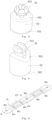
- Fig. 2 shows a structural schematic drawing of the pressing component 30 shown in Fig. 1 .
- the pressure plate 40 is provided with at least one through hole 401.
- the pressure block 50 comprises a first member 51, and a free end of the first member 51 is able to pass through the through hole 401 and press against the first side of the pressure plate 40.
- the pressure block 50 further comprises a second member 52.
- the second member 52 is provided with a first end 521, which presses against a second side of the pressure plate 40 opposite the first side, and a second end 522 which can press against the electronic component 1.
- Fig. 3 For the specific structure of the pressure block 50, see Fig. 3 .
- the free end of the first member 51 has a head part, and the head part is made of a deformable material and has a diameter larger than a diameter of the through hole 401, such that the head part is able to converge and deform towards the centre of the head part when passing through the through hole 401, and open out away from the centre after passing through the through hole 401 to press against the first side of the pressure plate 40.
- the head part is formed by multiple segments 511, and the multiple segments 511 are configured to be symmetrical or asymmetrical; for the specific structures, see Fig. 4 and Fig. 5 .
- the head part of the free end of the first member 51 has 4 segments 511 that are symmetrical; as best shown in Fig. 5 , the head part of the free end of the first member 51 has 2 segments 511 that are symmetrical.
- the segmented structure converges towards the centre, such that the first member 51 can contract and pass through the through hole 401, enabling the first member 51 to be more conveniently fitted into the pressure plate 40.
- the pressure plate 40 is in a shape of a flat plate, and an edge of the pressure plate 40 is provided with a reinforcing rib.
- the reinforcing rib 60 can increase the strength of the pressure plate 40.
- Two through holes 401 that are closest to either end of the pressure plate 40 and a through hole 401 that is at the exact middle thereof are used for mounting fastening members (such as bolts), and the through holes 401 at remaining positions of the pressure plate 40 are used for mounting the pressure blocks 50.
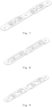
- the present disclosure further provides other examples of the structure of the pressure plate 40; for example, see Fig. 6 - Fig. 9 .
- the pressure plate 40 comprises at least one arc-shaped sheet-like structure 41.
- Each sheet-like structure comprises a top part 411 and two branch parts 412 extending from the top part.
- the stress distribution of various positions of the pressure plate 40 can be made uniform.
- Two through holes 401 that are closest to either end of the pressure plate 40 and a through hole 401 that is at the exact middle thereof are used for mounting fastening members (such as bolts), and the through holes 401 at remaining positions of the pressure plate 40 are used for mounting the pressure blocks 50.
- the pressure plate 40 comprises hollowed-out parts arranged around the through holes 401 or the pressure blocks 50, the hollowed-out parts are arranged symmetrically along the through holes 401 or the pressure blocks 50.
- the hollowed-out parts are arranged symmetrically with a central axis of the pressure plate 40 in a first direction as an axis of symmetry (marked as an x-axis), and are arranged symmetrically with a central axis of the pressure plate 40 perpendicular to the first direction as an axis of symmetry (marked as a y-axis).
- the hollowed-out parts arranged on the pressure plate 40 can somewhat deform when pressure on the electronic component 1 is especially large, thereby absorbing excess stress, preventing damage to the electronic component 1.
- the hollowed-out parts on the pressure plate 40 may be designed as various shapes, for example, see Fig. 7 - Fig. 9 .
- multiple hollowed-out parts as a whole on the pressure plate 40 assume a symmetrical structure, are arranged symmetrically with a central axis of the pressure plate 40 in a first direction as an axis of symmetry, and are arranged symmetrically with a central axis of the pressure plate 40 perpendicular to the first direction as an axis of symmetry, and the present disclosure does not impose a restriction on the shape of the hollowed-out parts on the pressure plate 40.
- the structures of the pressure plate 40 shown in Fig. 6 - Fig. 9 are merely some examples, and the present disclosure does not impose a restriction on the structure of the pressure plate 40.
- the reinforcing rib structure shown in Fig. 6 may be combined with the hollowed-out parts shown in Fig. 7 - Fig. 9 to form a new pressure plate 40.
- the pressure plate 40 is made of a metal or other material with reliable performance, for example a metal such as 301 stainless steel.
- Fig. 10 shows another heat dissipation device for an electronic component provided by at least one embodiment of the present disclosure.
- the difference between Fig. 10 and Fig. 1 is that a different pressing component 30 is used.
- the pressing component 30 shown in Fig. 2 is used in Fig. 1
- a pressing component 30 which combines the pressure block shown in Fig. 5 and the pressure plate shown in Fig. 7 is used in Fig. 10 .
- the heat dissipation device 2 may comprise an electrical insulation sheet 10 that is arranged between the heat dissipation component 20 and the electronic component 1, and that is used for separating the heat dissipation component 20 and the electronic component 1.
- the electrical insulation sheet 10 is made of an insulation material and, preferably, may be an electrical insulation material having good heat conductivity, for example, a heat-conducting silicone pad and a heat-conducting filler material, to promote heat exchange between the heat dissipation component 20 and the electronic component 1.
- the fixed structure may be a portion of the printed circuit board.
- the fixed structure may be a portion of the housing 7 of the electronic apparatus, that is, the pressure plate 40 is connected to a portion of the housing 7.
- the fixed structure may be a portion of the heat dissipation component 20, and the heat dissipation component 20 may be connected to the housing 7 of the electronic apparatus, that is, the pressure plate 40 is connected to a portion of the heat dissipation component 20, and the heat dissipation component 20 is connected to the housing 7.
- the fixed structure is a portion of the housing 7 of the electronic apparatus or the fixed structure is a portion of the heat dissipation component 20, and the heat dissipation component 20 may be connected to the housing 7 of the electronic apparatus.
- the pressure plate 40 is directly or indirectly fixed to the housing 7 of the electronic apparatus. This is especially advantageous in the case where the electronic apparatus is an onboard electronic apparatus, such as an onboard AC-DC converter or DC-AC converter or DC-DC converter.
- the running of a vehicle is generally accompanied by vibration of the onboard electronic apparatus; such vibration might cause loosening of the thermal contact between the electronic component 1 and the heat dissipation component 20, thereby weakening the heat dissipation effect.
- Having the pressure plate 40 directly or indirectly fixed to the housing 7 of the electronic apparatus enables the positioning of the pressure plate to be more reliable, thereby resisting the adverse effect of vibration on thermal contact.
- the pressure plate 40 is firmly connected to the fixed structure. It is possible to use an almost permanent connection (e.g., welding, adhesive, riveting, etc.), or a removable connection with one or more fasteners (e.g., a screw, bolt, snap-fit connection, etc.).
- the pressure plate 40 is fixed to the fixed structure by means of bolts 80, two ends and the middle of the pressure plate 40 are fixed with 3 bolts 80.
- the middle of the pressure plate 40 being fixed with a bolt 80 is to increase the pressure to which two pressure blocks 50 at the middle are subjected. If there is no middle bolt 80 for fixing, then the pressure to which the two pressure blocks 50 at the middle of the pressure plate are subjected is less.
- An action force applied by the pressure blocks 50 to the electronic component 1 may be adjusted by means of adjusting the bolts 80.
- At least one embodiment of the present disclosure further provides an electrical converter.
- the electrical converter comprises an AC-DC converter or a DC-AC converter or a DC-DC converter, and the electrical converter comprises the heat dissipation device 2 provided by at least one embodiment of the present disclosure.
- the electrical converter is provided with a housing, wherein the fixed structure is a portion of the housing, or the fixed structure is a portion of the heat dissipation component and the heat dissipation component is connected to the housing.
- At least one embodiment of the present disclosure further provides a vehicle, comprising the electrical converter provided in at least one embodiment of the present disclosure.
- the vehicle may be an electrified vehicle, such as a battery electric vehicle (BEV), a hybrid electric vehicle (HEV), a plug-in hybrid electric vehicle (PHEV), a range extended EV and a fuel cell electric vehicle (FCEV).
- BEV battery electric vehicle
- HEV hybrid electric vehicle
- PHEV plug-in hybrid electric vehicle
- FCEV fuel cell electric vehicle
- the vehicle may also be a hydrogen-powered vehicle.
Landscapes
- Engineering & Computer Science (AREA)
- Microelectronics & Electronic Packaging (AREA)
- Physics & Mathematics (AREA)
- Thermal Sciences (AREA)
- Power Engineering (AREA)
- Cooling Or The Like Of Electrical Apparatus (AREA)
Abstract
The present disclosure relates to a heat dissipation device for an electronic component. The heat dissipation device includes: a heat dissipation component arranged at a first side of the electronic component; and a pressing component arranged at a second side of the electronic component opposite the first side, wherein the pressing component includes a pressure plate and a pressure block, and the pressure block passes through the pressure plate and contacts the electronic component, and the pressure plate is connected to a fixed structure to apply a force towards the heat dissipation component to the electronic component via the pressure block. The present disclosure also relates to an electrical converter including the heat dissipation device, and a vehicle including the electrical converter.
Description
- The present disclosure relates to a heat dissipation device for an electronic component, in particular to a heat dissipation device that is fitted in a vehicle and is used for an electronic component of an electrical converter, ensuring good thermal contact between the heat dissipation device and the electronic component.
- The operating temperature of an electronic component directly affects its own reliability. For example, in a power conversion circuit of an AC-DC converter or DC-AC converter or DC-DC converter, a power semiconductor device serves an important function, and the operating state thereof directly affects the reliability of operation of the entire apparatus. During use, the power semiconductor device will consume a portion of energy and convert this to heat, with the result that the power semiconductor device heats up, and the junction temperature rises. When the junction temperature exceeds a safety threshold, the current will increase sharply, and this may even cause a transistor to burn out. Thus, heat needs to be rapidly released to the surroundings by means of a heat dissipation device, to lower the operating temperature of the electronic component. To ensure stable operation of the heat dissipation device, good thermal contact between the heat dissipation device and the electronic component needs to be maintained.
- An object of the present disclosure is to propose a heat dissipation device for an electronic component, wherein the heat dissipation device has a simple manufacturing process and saves on costs, can protect the electronic component against damage, has a simple disassembly process, and can enhance electrical insulation.
- At least one embodiment of the present disclosure provides a heat dissipation device for an electronic component. The heat dissipation device comprises: a heat dissipation component arranged at a first side of the electronic component; and a pressing component arranged at a second side of the electronic component opposite the first side; wherein the pressing component comprises a pressure plate and a pressure block, the pressure block passes through the pressure plate and contacts the electronic component, and the pressure plate is connected to a fixed structure to apply a force towards the heat dissipation component to the electronic component via the pressure block.
- For example, in the heat dissipation device provided by at least one embodiment of the present disclosure, the pressure plate is provided with at least one through hole, the pressure block comprises a first member, and a free end of the first member is able to pass through the through hole and press against a first side of the pressure plate.
- For example, in the heat dissipation device provided by at least one embodiment of the present disclosure, the pressure block further comprises a second member, the second member is configured to have a first end that presses against a second side of the pressure plate opposite the first side, and a second end that is able to press against the electronic component.
- For example, in the heat dissipation device provided by at least one embodiment of the present disclosure, the free end of the first member has a head part, and the head part is made of a deformable material and has a diameter larger than a diameter of the through hole, such that the head part is able to converge and deform towards the centre of the head part when passing through the through hole, and open out away from the centre after passing through the through hole to press against the first side of the pressure plate.
- For example, in the heat dissipation device provided by at least one embodiment of the present disclosure, the head part is formed by multiple segments, and the multiple segments are configured to be symmetrical or asymmetrical.
- For example, in the heat dissipation device provided by at least one embodiment of the present disclosure, the pressure plate is in a shape of a flat plate, and an edge of the pressure plate is provided with a reinforcing rib.
- For example, in the heat dissipation device provided by at least one embodiment of the present disclosure, the pressure plate comprises at least one arc-shaped sheet-like structure, each sheet-like structure comprises a top part and two branch parts extending from the top part.
- For example, in the heat dissipation device provided by at least one embodiment of the present disclosure, the pressure plate comprises a hollowed-out part arranged around the through hole or the pressure block, the hollowed-out part is arranged symmetrically along the through hole or the pressure block.
- For example, in the heat dissipation device provided by at least one embodiment of the present disclosure, the pressing component comprises multiple pressure blocks, the multiple pressure blocks are distributed in a first direction and mounted on the pressure plate, the hollowed-out part is arranged symmetrically with a central axis of the pressure plate in a first direction as an axis of symmetry, and is arranged symmetrically with a central axis of the pressure plate perpendicular to the first direction as an axis of symmetry.
- For example, in the heat dissipation device provided by at least one embodiment of the present disclosure, material of the pressure block comprises plastic or rubber.
- For example, in the heat dissipation device provided by at least one embodiment of the present disclosure, the electronic component is accommodated in a housing and electrically connected to a printed circuit board, and wherein the fixed structure is a portion of the heat dissipation component or a portion of the housing, and the pressing component is firmly connected to the fixed structure.
- For example, the heat dissipation device provided by at least one embodiment of the present disclosure further comprises an electrical insulation sheet, the electrical insulation sheet is arranged between the heat dissipation component and the electronic component.
- For example, in the heat dissipation device provided by at least one embodiment of the present disclosure, the electronic component comprises a MOSFET.
- Another embodiment of the present disclosure further provides an electrical converter, the electrical converter comprises an AC-DC converter or a DC-AC converter or a DC-DC converter, and the electrical converter comprises the heat dissipation device provided by at least one embodiment of the present disclosure.
- A further embodiment of the present disclosure further provides a vehicle, comprising the electrical converter provided in at least one embodiment of the present disclosure.
- To explain the technical solutions of embodiments of the present disclosure more clearly, the drawings which need to be used in describing the embodiments are described in simple terms below. Obviously, the drawings in the description below are merely some embodiments of the present disclosure, and those skilled in the art could obtain other drawings based on these drawings without expending inventive effort. The drawings below have not been drawn by meticulously reducing or enlarging actual dimensions in equal proportion, but focus on showing the substance of the present disclosure.
-
Fig. 1 is a structural schematic drawing of a heat dissipation device for an electronic component provided according to at least one embodiment of the present disclosure; -
Fig. 2 is a structural schematic drawing of a pressing component provided according to at least one embodiment of the present disclosure; -
Fig. 3 is a structural schematic drawing of a pressure block provided according to at least one embodiment of the present disclosure; -
Fig. 4 is a structural schematic drawing of another pressure block provided according to at least one embodiment of the present disclosure; -
Fig. 5 is a structural schematic drawing of another pressure block provided according to at least one embodiment of the present disclosure; -
Fig. 6 is a structural schematic drawing of a pressure plate provided according to at least one embodiment of the present disclosure; -
Fig. 7 is a structural schematic drawing of another pressure plate provided according to at least one embodiment of the present disclosure; -
Fig. 8 is a structural schematic drawing of another pressure plate provided according to at least one embodiment of the present disclosure; -
Fig. 9 is a structural schematic drawing of another pressure plate provided according to at least one embodiment of the present disclosure; -
Fig. 10 is a structural schematic drawing of another heat dissipation device for an electronic component provided according to at least one embodiment of the present disclosure. - In all the drawings, identical or similar components are denoted by identical reference signs.
- To clarify the objective, technical solutions and advantages of embodiments of the present disclosure, the technical solutions of the embodiments of the present disclosure are described clearly and completely below in conjunction with the drawings of the embodiments of the present disclosure.
- Unless defined otherwise, the technical or scientific terms used herein shall have the common meanings as understood by those of ordinary skill in the art to which the present disclosure belongs. Words such as "an", "a" or "the" used in the description and the claims of the patent application disclosed herein do not indicate a quantity limit, but mean that there is at least one. "Comprise", "include" or any other similar term means that the element or object appearing before the term covers the elements or objects and equivalents thereof listed after the term but does not exclude other elements or objects. Words such as "connected" or "linked" are not restricted to a physical or mechanical connection, and may include an electrical connection, whether direct or indirect.
- In order to facilitate description, the drawings of the present disclosure accordingly simplify or omit components commonly used in the art, such as external connection lines and other components that are irrelevant to the description of the present disclosure. These omitted or simplified components do not affect the understanding of the content of the present disclosure by a person skilled in the art.
- The use of a pressure plate and bolts to maintain contact between the heat dissipation device and the electronic component is known in the prior art. Specifically, the pressure plate is directly placed above the electronic component, and connected to a heat dissipation component at a suitable position, such that the electronic component is pressed tightly against the heat dissipation component by means of the pressure plate. The most obvious drawback of this solution is that the rigid action force of the pressure plate is applied to the electronic component directly, and this might cause damage to the electronic component, which has a rather fragile structure.
- The use of an elastic piece to maintain contact between the heat dissipation device and the electronic component is also known in the prior art. Specifically, the elastic piece is placed above the electronic component, and connected to a heat dissipation component at a suitable position, such that the electronic component is pressed tightly against the heat dissipation component. This solution requires a hard elastic piece, which is difficult to process, and if the elastic piece is directly pressed on the electronic component, problems of damage to the electronic component and voltage emerge.
- At least one embodiment of the present disclosure provides a heat dissipation device for an electronic component, the heat dissipation device comprises: a heat dissipation component arranged at a first side of the electronic component; and a pressing component arranged at a second side of the electronic component opposite the first side; wherein the pressing component comprises a pressure plate and a pressure block, the pressure block passes through the pressure plate and contacts the electronic component, and the pressure plate is connected to a fixed structure to apply a force towards the heat dissipation component to the electronic component via the pressure block.
- The heat dissipation device provided by the present disclosure at least overcomes the above defect in the prior art. The heat dissipation device has a simple manufacturing process and saves on costs, can protect the electronic component against damage, has a simple disassembly process, and can enhance electrical insulation.
-
Fig. 1 shows aheat dissipation device 2 for anelectronic component 1 provided according to at least one embodiment of the present disclosure. Theelectronic component 1, for example, is a circuit component part of an electronic apparatus. In some embodiments, the electronic apparatus is for example an onboard AC-DC converter or DC-AC converter or DC-DC converter. These electronic apparatuses often generate large amounts of heat with high currents during operation. However, it should be understood that theheat dissipation device 2 according to the present disclosure may also be used in other industrial fields comprising consumer electronics, electric household appliances, engineering machinery and electrical apparatuses. - As shown in
Fig. 1 , the electronic apparatus comprises ahousing 7 and a printed circuit board (not shown) accommodated in thehousing 7. For convenience of description, only part of the electronic apparatus is shown inFig. 1 . At least oneelectronic component 1, for example, is electrically connected to the printed circuit board by means of pins. InFig. 1 , the number ofelectronic components 1 is 4 for example. It should be explained that the number ofelectronic components 1 being 4 is merely an example, and the present disclosure does not impose a restriction on the number ofelectronic components 1. Theelectronic component 1, for example, is a power semiconductor device, such as a MOSFET (metal-oxide-semiconductor field-effect transistor), which will consume a portion of energy and convert this to a large amount of heat during use, with the result that theelectronic component 1 heats up, and the junction temperature rises. It should be explained that the MOSFET is merely an example, and the present disclosure does not impose a restriction on the type of theelectronic component 1. For this reason, theheat dissipation device 2 is provided for the at least oneelectronic component 1, as described in detail below. - The
heat dissipation device 2 comprises aheat dissipation component 20, also called a heat sink, that is arranged at a lower side of theelectronic component 1. Theheat dissipation component 20 can undergo heat exchange with theelectronic component 1 and absorb the heat generated by theelectronic component 1 during operation, to lower the temperature of theelectronic component 1. In some embodiments, theheat dissipation component 20 is formed as a portion of thehousing 7, as shown inFig. 1 . In other embodiments, theheat dissipation component 20 and thehousing 7 are formed as separate components. - As shown in
Fig. 1 , theheat dissipation device 2 comprises apressing component 30. Thepressing component 30 is arranged on an upper side of theelectronic component 1, i.e., at the side opposite theheat dissipation component 20. - As shown in
Fig. 1 , thepressing component 30 comprises apressure plate 40 and apressure block 50, and the number of pressure blocks 50 is 4, to correspond to the number ofelectronic components 1. It should be explained that the present disclosure does not impose a restriction on the number of pressure blocks 50, which may be chosen at will according to a heat sink. The pressure blocks 50 are mounted on thepressure plate 40 in a first direction. The first direction is an arrangement direction of theelectronic components 1. Thepressure block 50 passes through thepressure plate 40 and contacts theelectronic components 1, and thepressure plate 40 is connected to a fixed structure to apply a force towards theheat dissipation component 20 to theelectronic component 1 via thepressure block 50. - For example, in some embodiments of the present disclosure, material of the
pressure block 50 comprises plastic or rubber. - Since the plastic or rubber material is elastic, a rigid action force being applied to the electronic component, causing damage thereto, when the electronic component is pressed on is prevented. Moreover, the plastic or rubber material may enhance electrical insulation.
- The plastic or rubber material described above are merely some examples. The
pressure block 50 may also be made of other materials with good insulation and relatively low hardness, as long as application of a potentially damaging rigid action force to theelectronic component 1 can be prevented, and the present disclosure does not impose a restriction on this. - This configuration according to the present disclosure can avoid the direct application of a rigid action force to the
electronic component 1, preventing theelectronic component 1 from experiencing local concentrated strain and thereby being damaged. In addition, since thepressure plate 40 is connected to the fixed structure, as time passes, thepressure block 50 can still apply a sufficient elastic action force to theelectronic component 1, thereby forming stable and reliable thermal contact between theelectronic component 1 and theheat dissipation component 20. - Moreover, the manufacturing process for the heat dissipation device is simple, and using a pressure block of plastic or rubber material can save on costs.
-
Fig. 2 shows a structural schematic drawing of thepressing component 30 shown inFig. 1 . - As shown in
Fig. 2 , thepressure plate 40 is provided with at least one throughhole 401. Thepressure block 50 comprises afirst member 51, and a free end of thefirst member 51 is able to pass through the throughhole 401 and press against the first side of thepressure plate 40. Thepressure block 50 further comprises asecond member 52. Thesecond member 52 is provided with afirst end 521, which presses against a second side of thepressure plate 40 opposite the first side, and asecond end 522 which can press against theelectronic component 1. For the specific structure of thepressure block 50, seeFig. 3 . - As shown in
Fig. 3 , the free end of thefirst member 51 has a head part, and the head part is made of a deformable material and has a diameter larger than a diameter of the throughhole 401, such that the head part is able to converge and deform towards the centre of the head part when passing through the throughhole 401, and open out away from the centre after passing through the throughhole 401 to press against the first side of thepressure plate 40. - In order to better fit the
first member 51 into thepressure plate 40, for example, in some embodiments of the present disclosure, the head part is formed bymultiple segments 511, and themultiple segments 511 are configured to be symmetrical or asymmetrical; for the specific structures, seeFig. 4 and Fig. 5 . - As shown in
Fig. 4 , the head part of the free end of thefirst member 51 has 4segments 511 that are symmetrical; as best shown inFig. 5 , the head part of the free end of thefirst member 51 has 2segments 511 that are symmetrical. In the process of fitting thefirst member 51 into thepressure plate 40, the segmented structure converges towards the centre, such that thefirst member 51 can contract and pass through the throughhole 401, enabling thefirst member 51 to be more conveniently fitted into thepressure plate 40. - It should be explained that the structures of the
pressure block 50 shown inFig. 3 - Fig. 5 are merely some examples, and the present disclosure does not impose a restriction on the specific structure of thepressure block 50. - Returning to
Fig. 2 , as shown inFig. 2 , thepressure plate 40 is in a shape of a flat plate, and an edge of thepressure plate 40 is provided with a reinforcing rib. The reinforcingrib 60 can increase the strength of thepressure plate 40. Two throughholes 401 that are closest to either end of thepressure plate 40 and a throughhole 401 that is at the exact middle thereof are used for mounting fastening members (such as bolts), and the throughholes 401 at remaining positions of thepressure plate 40 are used for mounting the pressure blocks 50. - Besides the structure of the
pressure plate 40 shown inFig. 2 , the present disclosure further provides other examples of the structure of thepressure plate 40; for example, seeFig. 6 - Fig. 9 . - As shown in
Fig. 6 , thepressure plate 40 comprises at least one arc-shaped sheet-like structure 41. Each sheet-like structure comprises atop part 411 and twobranch parts 412 extending from the top part. By means of adding an undulating design to thepressure plate 40, the stress distribution of various positions of thepressure plate 40 can be made uniform. Two throughholes 401 that are closest to either end of thepressure plate 40 and a throughhole 401 that is at the exact middle thereof are used for mounting fastening members (such as bolts), and the throughholes 401 at remaining positions of thepressure plate 40 are used for mounting the pressure blocks 50. Thepressure plate 40 comprises hollowed-out parts arranged around the throughholes 401 or the pressure blocks 50, the hollowed-out parts are arranged symmetrically along the throughholes 401 or the pressure blocks 50. The hollowed-out parts are arranged symmetrically with a central axis of thepressure plate 40 in a first direction as an axis of symmetry (marked as an x-axis), and are arranged symmetrically with a central axis of thepressure plate 40 perpendicular to the first direction as an axis of symmetry (marked as a y-axis). - The hollowed-out parts arranged on the
pressure plate 40 can somewhat deform when pressure on theelectronic component 1 is especially large, thereby absorbing excess stress, preventing damage to theelectronic component 1. - The hollowed-out parts on the
pressure plate 40 may be designed as various shapes, for example, seeFig. 7 - Fig. 9 . InFig.7 - Fig. 9 , multiple hollowed-out parts as a whole on thepressure plate 40 assume a symmetrical structure, are arranged symmetrically with a central axis of thepressure plate 40 in a first direction as an axis of symmetry, and are arranged symmetrically with a central axis of thepressure plate 40 perpendicular to the first direction as an axis of symmetry, and the present disclosure does not impose a restriction on the shape of the hollowed-out parts on thepressure plate 40. - It should be explained that the structures of the
pressure plate 40 shown inFig. 6 - Fig. 9 are merely some examples, and the present disclosure does not impose a restriction on the structure of thepressure plate 40. For example, the reinforcing rib structure shown inFig. 6 may be combined with the hollowed-out parts shown inFig. 7 - Fig. 9 to form anew pressure plate 40. - For example, in some embodiments of the present disclosure, the
pressure plate 40 is made of a metal or other material with reliable performance, for example a metal such as 301 stainless steel. -
Fig. 10 shows another heat dissipation device for an electronic component provided by at least one embodiment of the present disclosure. The difference betweenFig. 10 andFig. 1 is that a differentpressing component 30 is used. Thepressing component 30 shown inFig. 2 is used inFig. 1 , whereas apressing component 30 which combines the pressure block shown inFig. 5 and the pressure plate shown inFig. 7 is used inFig. 10 . - For example, in some embodiments of the present disclosure, the
heat dissipation device 2 may comprise anelectrical insulation sheet 10 that is arranged between theheat dissipation component 20 and theelectronic component 1, and that is used for separating theheat dissipation component 20 and theelectronic component 1. Theelectrical insulation sheet 10 is made of an insulation material and, preferably, may be an electrical insulation material having good heat conductivity, for example, a heat-conducting silicone pad and a heat-conducting filler material, to promote heat exchange between theheat dissipation component 20 and theelectronic component 1. - For other components of the heat dissipation device shown in
Fig. 10 , see the relevant descriptions ofFig. 1 which will not be repeated here. - It should be explained that other different combinations of pressure blocks and pressure plates may further be used to form different pressing components for the heat dissipation device, and the present disclosure does not impose a restriction on this.
- In some embodiments, the fixed structure may be a portion of the printed circuit board.
- In some embodiments, the fixed structure may be a portion of the
housing 7 of the electronic apparatus, that is, thepressure plate 40 is connected to a portion of thehousing 7. - In some embodiments, the fixed structure may be a portion of the
heat dissipation component 20, and theheat dissipation component 20 may be connected to thehousing 7 of the electronic apparatus, that is, thepressure plate 40 is connected to a portion of theheat dissipation component 20, and theheat dissipation component 20 is connected to thehousing 7. - The fixed structure is a portion of the
housing 7 of the electronic apparatus or the fixed structure is a portion of theheat dissipation component 20, and theheat dissipation component 20 may be connected to thehousing 7 of the electronic apparatus. In these two configurations, thepressure plate 40 is directly or indirectly fixed to thehousing 7 of the electronic apparatus. This is especially advantageous in the case where the electronic apparatus is an onboard electronic apparatus, such as an onboard AC-DC converter or DC-AC converter or DC-DC converter. The running of a vehicle is generally accompanied by vibration of the onboard electronic apparatus; such vibration might cause loosening of the thermal contact between theelectronic component 1 and theheat dissipation component 20, thereby weakening the heat dissipation effect. Having thepressure plate 40 directly or indirectly fixed to thehousing 7 of the electronic apparatus enables the positioning of the pressure plate to be more reliable, thereby resisting the adverse effect of vibration on thermal contact. - In some embodiments, the
pressure plate 40 is firmly connected to the fixed structure. It is possible to use an almost permanent connection (e.g., welding, adhesive, riveting, etc.), or a removable connection with one or more fasteners (e.g., a screw, bolt, snap-fit connection, etc.). As shown inFig. 1 andFig. 10 , thepressure plate 40 is fixed to the fixed structure by means ofbolts 80, two ends and the middle of thepressure plate 40 are fixed with 3bolts 80. The middle of thepressure plate 40 being fixed with abolt 80 is to increase the pressure to which two pressure blocks 50 at the middle are subjected. If there is nomiddle bolt 80 for fixing, then the pressure to which the two pressure blocks 50 at the middle of the pressure plate are subjected is less. An action force applied by the pressure blocks 50 to theelectronic component 1 may be adjusted by means of adjusting thebolts 80. - At least one embodiment of the present disclosure further provides an electrical converter. The electrical converter comprises an AC-DC converter or a DC-AC converter or a DC-DC converter, and the electrical converter comprises the
heat dissipation device 2 provided by at least one embodiment of the present disclosure. - For example, in the electrical converter provided by at least one embodiment of the present disclosure, the electrical converter is provided with a housing, wherein the fixed structure is a portion of the housing, or the fixed structure is a portion of the heat dissipation component and the heat dissipation component is connected to the housing.
- At least one embodiment of the present disclosure further provides a vehicle, comprising the electrical converter provided in at least one embodiment of the present disclosure. The vehicle may be an electrified vehicle, such as a battery electric vehicle (BEV), a hybrid electric vehicle (HEV), a plug-in hybrid electric vehicle (PHEV), a range extended EV and a fuel cell electric vehicle (FCEV). The vehicle may also be a hydrogen-powered vehicle.
- Certain features, structures or characteristics in one or more embodiments of the present disclosure may be combined appropriately.
- The above is a description of the present disclosure and should not be construed as a limitation thereon. Although several exemplary embodiments of the present disclosure have been described, those of ordinary skill in the art will readily understand that many modifications may be made to the exemplary embodiments without departing from the novel teaching and advantages of the present disclosure. Therefore, all such modifications are intended to be included in the scope of the present disclosure as defined by the claims. It should be understood that the above is a description of the present disclosure, that the present disclosure should not be deemed to be limited to the specific embodiments disclosed herein, and that modifications to the embodiments disclosed herein and other embodiments are intended to be included within the scope of the present disclosure.
Claims (15)
- A heat dissipation device (2) for an electronic component (1), characterized in that the heat dissipation device (2) comprises:a heat dissipation component (20) arranged at a first side of the electronic component (1); anda pressing component (30) arranged at a second side of the electronic component (1) opposite the first side,wherein the pressing component (30) comprises a pressure plate (40) and a pressure block (50), the pressure block (50) passes through the pressure plate (40) and contacts the electronic component (1), and the pressure plate (40) is connected to a fixed structure to apply a force towards the heat dissipation component (20) to the electronic component (1) via the pressure block (50).
- The heat dissipation device (2) according to claim 1, characterized in that the pressure plate (40) is provided with at least one through hole (401), the pressure block (50) comprises a first member (51), and a free end of the first member (51) is able to pass through the through hole (401) and press against a first side of the pressure plate (40).
- The heat dissipation device (2) according to claim 2, characterized in that the pressure block (50) further comprises a second member (52), the second member (52) is configured to have a first end (521) that presses against a second side of the pressure plate (40) opposite the first side, and a second end (522) that is able to press against the electronic component (1).
- The heat dissipation device (2) according to claim 2, characterized in that the free end of the first member (51) has a head part, and the head part is made of a deformable material and has a diameter larger than a diameter of the through hole (401), such that the head part is able to converge and deform towards the centre of the head part when passing through the through hole (401), and open out away from the centre after passing through the through hole (401) to press against the first side of the pressure plate (40).
- The heat dissipation device (2) according to claim 4, characterized in that the head part is formed by multiple segments (511), and the multiple segments (511) are configured to be symmetrical or asymmetrical.
- The heat dissipation device (2) according to claim 1, characterized in that the pressure plate (40) is in a shape of a flat plate, and an edge of the pressure plate (40) is provided with a reinforcing rib.
- The heat dissipation device (2) according to claim 1, characterized in that the pressure plate (40) comprises at least one arc-shaped sheet-like structure (41), each sheet-like structure (41) comprises a top part (411) and two branch parts (412) extending from the top part.
- The heat dissipation device (2) according to claim 7, characterized in that the pressure plate (40) comprises a hollowed-out part arranged around the through hole (401) or the pressure block (50), the hollowed-out part is arranged symmetrically along the through hole (401) or the pressure block (50).
- The heat dissipation device (2) according to claim 8, characterized in that the pressing component (30) comprises multiple pressure blocks (50), the multiple pressure blocks (50) are distributed in a first direction and mounted on the pressure plate (40), the hollowed-out part is arranged symmetrically with a central axis of the pressure plate (40) in a first direction as an axis of symmetry, and is arranged symmetrically with a central axis of the pressure plate (40) perpendicular to the first direction as an axis of symmetry.
- The heat dissipation device (2) according to any one of claims 1 to 9, characterized in that material of the pressure block (50) comprises plastic or rubber.
- The heat dissipation device (2) according to any one of claims 1 to 9, characterized in that the electronic component (1) is accommodated in a housing (7) and is electrically connected to a printed circuit board, wherein the fixed structure is a portion of the heat dissipation component (20) or a portion of the housing (7) or a portion of the printed circuit board, and the pressing component (30) is firmly connected to the fixed structure.
- The heat dissipation device (2) according to any one of claims 1 to 9, characterized in that the heat dissipation device (2) further comprises an electrical insulation sheet (10), and the electrical insulation sheet (10) is arranged between the heat dissipation component (20) and the electronic component (1).
- The heat dissipation device (2) according to any one of claims 1 to 9, characterized in that the electronic component (1) comprises a MOSFET.
- An electrical converter, characterized in that the electrical converter comprises an AC-DC converter or a DC-AC converter or a DC-DC converter, and the electrical converter comprises the heat dissipation device according to any one of claims 1 to 13.
- A vehicle, characterized in that the vehicle comprises the electrical converter according to claim 14.
Applications Claiming Priority (1)
| Application Number | Priority Date | Filing Date | Title |
|---|---|---|---|
| CN202310875663.7A CN119324184A (en) | 2023-07-17 | 2023-07-17 | Heat dissipation device for electronic component, electric converter and vehicle |
Publications (1)
| Publication Number | Publication Date |
|---|---|
| EP4496443A1 true EP4496443A1 (en) | 2025-01-22 |
Family
ID=91898849
Family Applications (1)
| Application Number | Title | Priority Date | Filing Date |
|---|---|---|---|
| EP24187765.3A Pending EP4496443A1 (en) | 2023-07-17 | 2024-07-10 | Heat dissipation device for electronic component, electrical converter and vehicle |
Country Status (2)
| Country | Link |
|---|---|
| EP (1) | EP4496443A1 (en) |
| CN (1) | CN119324184A (en) |
Citations (4)
| Publication number | Priority date | Publication date | Assignee | Title |
|---|---|---|---|---|
| CN203277351U (en) * | 2013-04-20 | 2013-11-06 | 北京汇能精电科技有限公司 | Thermal conduction and radiation compressing structure of power transistor |
| CN204810775U (en) * | 2015-07-24 | 2015-11-25 | 北京汇能精电科技股份有限公司 | Pressing device |
| JP5832215B2 (en) * | 2011-09-28 | 2015-12-16 | 株式会社ケーヒン | Semiconductor control device |
| US20200321263A1 (en) * | 2019-04-05 | 2020-10-08 | Tm4 Inc. | Thermal interface for plurality of discrete electronic devices |
-
2023
- 2023-07-17 CN CN202310875663.7A patent/CN119324184A/en active Pending
-
2024
- 2024-07-10 EP EP24187765.3A patent/EP4496443A1/en active Pending
Patent Citations (4)
| Publication number | Priority date | Publication date | Assignee | Title |
|---|---|---|---|---|
| JP5832215B2 (en) * | 2011-09-28 | 2015-12-16 | 株式会社ケーヒン | Semiconductor control device |
| CN203277351U (en) * | 2013-04-20 | 2013-11-06 | 北京汇能精电科技有限公司 | Thermal conduction and radiation compressing structure of power transistor |
| CN204810775U (en) * | 2015-07-24 | 2015-11-25 | 北京汇能精电科技股份有限公司 | Pressing device |
| US20200321263A1 (en) * | 2019-04-05 | 2020-10-08 | Tm4 Inc. | Thermal interface for plurality of discrete electronic devices |
Also Published As
| Publication number | Publication date |
|---|---|
| CN119324184A (en) | 2025-01-17 |
Similar Documents
| Publication | Publication Date | Title |
|---|---|---|
| US8630093B2 (en) | Semiconductor device | |
| US9147634B2 (en) | Semiconductor device, and on-board power conversion device | |
| US10939585B2 (en) | Fixing structure of electronic component | |
| JP2019057459A (en) | Electric connection member | |
| KR20150060539A (en) | Power conversion device and power conversion assembly | |
| JP5835315B2 (en) | Power storage module unit and method for manufacturing power storage module unit | |
| CN113748751A (en) | Circuit structure | |
| US11925007B2 (en) | Heat dissipation assembly structure for power part | |
| CN109891661A (en) | Battery module with the fixed structure for temperature sensor | |
| JP2012028552A (en) | Semiconductor module case structure | |
| US20230007807A1 (en) | Heat dissipation device for electronic component | |
| KR101932052B1 (en) | Insulator and connector for thermoelectric devices in a thermoelectric assembly | |
| EP4496443A1 (en) | Heat dissipation device for electronic component, electrical converter and vehicle | |
| TW200301069A (en) | Power feed device | |
| CN218569055U (en) | Battery modules and electrical devices | |
| JP7543911B2 (en) | Power storage device | |
| WO2021057950A1 (en) | Electronic device and fixing module thereof for fixing element | |
| JP2016100045A (en) | Power storage device | |
| KR20260023488A (en) | Electrical device, electric drive system and vehicle | |
| JP7554190B2 (en) | Electronic Assembly | |
| CN216761665U (en) | Clamping spring, electronic device and motor vehicle | |
| CN220191313U (en) | Heat dissipation device for electronic element, power converter and vehicle | |
| JP7548170B2 (en) | Power Conversion Equipment | |
| CN223110370U (en) | Electrical devices, electric drive systems and vehicles | |
| CN222442098U (en) | Power module and charging equipment |
Legal Events
| Date | Code | Title | Description |
|---|---|---|---|
| PUAI | Public reference made under article 153(3) epc to a published international application that has entered the european phase |
Free format text: ORIGINAL CODE: 0009012 |
|
| STAA | Information on the status of an ep patent application or granted ep patent |
Free format text: STATUS: REQUEST FOR EXAMINATION WAS MADE |
|
| 17P | Request for examination filed |
Effective date: 20240710 |
|
| AK | Designated contracting states |
Kind code of ref document: A1 Designated state(s): AL AT BE BG CH CY CZ DE DK EE ES FI FR GB GR HR HU IE IS IT LI LT LU LV MC ME MK MT NL NO PL PT RO RS SE SI SK SM TR |