EP4496107A1 - Rechargeable battery module - Google Patents
Rechargeable battery module Download PDFInfo
- Publication number
- EP4496107A1 EP4496107A1 EP24188502.9A EP24188502A EP4496107A1 EP 4496107 A1 EP4496107 A1 EP 4496107A1 EP 24188502 A EP24188502 A EP 24188502A EP 4496107 A1 EP4496107 A1 EP 4496107A1
- Authority
- EP
- European Patent Office
- Prior art keywords
- unit
- unit portion
- thin film
- busbar
- battery module
- Prior art date
- Legal status (The legal status is an assumption and is not a legal conclusion. Google has not performed a legal analysis and makes no representation as to the accuracy of the status listed.)
- Pending
Links
Images






Classifications
-
- H—ELECTRICITY
- H01—ELECTRIC ELEMENTS
- H01M—PROCESSES OR MEANS, e.g. BATTERIES, FOR THE DIRECT CONVERSION OF CHEMICAL ENERGY INTO ELECTRICAL ENERGY
- H01M50/00—Constructional details or processes of manufacture of the non-active parts of electrochemical cells other than fuel cells, e.g. hybrid cells
- H01M50/50—Current conducting connections for cells or batteries
- H01M50/569—Constructional details of current conducting connections for detecting conditions inside cells or batteries, e.g. details of voltage sensing terminals
-
- H—ELECTRICITY
- H01—ELECTRIC ELEMENTS
- H01M—PROCESSES OR MEANS, e.g. BATTERIES, FOR THE DIRECT CONVERSION OF CHEMICAL ENERGY INTO ELECTRICAL ENERGY
- H01M50/00—Constructional details or processes of manufacture of the non-active parts of electrochemical cells other than fuel cells, e.g. hybrid cells
- H01M50/50—Current conducting connections for cells or batteries
- H01M50/502—Interconnectors for connecting terminals of adjacent batteries; Interconnectors for connecting cells outside a battery casing
- H01M50/514—Methods for interconnecting adjacent batteries or cells
- H01M50/516—Methods for interconnecting adjacent batteries or cells by welding, soldering or brazing
-
- B—PERFORMING OPERATIONS; TRANSPORTING
- B23—MACHINE TOOLS; METAL-WORKING NOT OTHERWISE PROVIDED FOR
- B23K—SOLDERING OR UNSOLDERING; WELDING; CLADDING OR PLATING BY SOLDERING OR WELDING; CUTTING BY APPLYING HEAT LOCALLY, e.g. FLAME CUTTING; WORKING BY LASER BEAM
- B23K26/00—Working by laser beam, e.g. welding, cutting or boring
- B23K26/20—Bonding
- B23K26/21—Bonding by welding
-
- H—ELECTRICITY
- H01—ELECTRIC ELEMENTS
- H01M—PROCESSES OR MEANS, e.g. BATTERIES, FOR THE DIRECT CONVERSION OF CHEMICAL ENERGY INTO ELECTRICAL ENERGY
- H01M10/00—Secondary cells; Manufacture thereof
- H01M10/42—Methods or arrangements for servicing or maintenance of secondary cells or secondary half-cells
- H01M10/425—Structural combination with electronic components, e.g. electronic circuits integrated to the outside of the casing
-
- H—ELECTRICITY
- H01—ELECTRIC ELEMENTS
- H01M—PROCESSES OR MEANS, e.g. BATTERIES, FOR THE DIRECT CONVERSION OF CHEMICAL ENERGY INTO ELECTRICAL ENERGY
- H01M10/00—Secondary cells; Manufacture thereof
- H01M10/42—Methods or arrangements for servicing or maintenance of secondary cells or secondary half-cells
- H01M10/48—Accumulators combined with arrangements for measuring, testing or indicating the condition of cells, e.g. the level or density of the electrolyte
- H01M10/482—Accumulators combined with arrangements for measuring, testing or indicating the condition of cells, e.g. the level or density of the electrolyte for several batteries or cells simultaneously or sequentially
-
- H—ELECTRICITY
- H01—ELECTRIC ELEMENTS
- H01M—PROCESSES OR MEANS, e.g. BATTERIES, FOR THE DIRECT CONVERSION OF CHEMICAL ENERGY INTO ELECTRICAL ENERGY
- H01M50/00—Constructional details or processes of manufacture of the non-active parts of electrochemical cells other than fuel cells, e.g. hybrid cells
- H01M50/20—Mountings; Secondary casings or frames; Racks, modules or packs; Suspension devices; Shock absorbers; Transport or carrying devices; Holders
- H01M50/204—Racks, modules or packs for multiple batteries or multiple cells
-
- H—ELECTRICITY
- H01—ELECTRIC ELEMENTS
- H01M—PROCESSES OR MEANS, e.g. BATTERIES, FOR THE DIRECT CONVERSION OF CHEMICAL ENERGY INTO ELECTRICAL ENERGY
- H01M50/00—Constructional details or processes of manufacture of the non-active parts of electrochemical cells other than fuel cells, e.g. hybrid cells
- H01M50/20—Mountings; Secondary casings or frames; Racks, modules or packs; Suspension devices; Shock absorbers; Transport or carrying devices; Holders
- H01M50/204—Racks, modules or packs for multiple batteries or multiple cells
- H01M50/207—Racks, modules or packs for multiple batteries or multiple cells characterised by their shape
- H01M50/209—Racks, modules or packs for multiple batteries or multiple cells characterised by their shape adapted for prismatic or rectangular cells
-
- H—ELECTRICITY
- H01—ELECTRIC ELEMENTS
- H01M—PROCESSES OR MEANS, e.g. BATTERIES, FOR THE DIRECT CONVERSION OF CHEMICAL ENERGY INTO ELECTRICAL ENERGY
- H01M50/00—Constructional details or processes of manufacture of the non-active parts of electrochemical cells other than fuel cells, e.g. hybrid cells
- H01M50/50—Current conducting connections for cells or batteries
- H01M50/502—Interconnectors for connecting terminals of adjacent batteries; Interconnectors for connecting cells outside a battery casing
- H01M50/503—Interconnectors for connecting terminals of adjacent batteries; Interconnectors for connecting cells outside a battery casing characterised by the shape of the interconnectors
-
- H—ELECTRICITY
- H01—ELECTRIC ELEMENTS
- H01M—PROCESSES OR MEANS, e.g. BATTERIES, FOR THE DIRECT CONVERSION OF CHEMICAL ENERGY INTO ELECTRICAL ENERGY
- H01M50/00—Constructional details or processes of manufacture of the non-active parts of electrochemical cells other than fuel cells, e.g. hybrid cells
- H01M50/50—Current conducting connections for cells or batteries
- H01M50/502—Interconnectors for connecting terminals of adjacent batteries; Interconnectors for connecting cells outside a battery casing
- H01M50/505—Interconnectors for connecting terminals of adjacent batteries; Interconnectors for connecting cells outside a battery casing comprising a single busbar
-
- H—ELECTRICITY
- H01—ELECTRIC ELEMENTS
- H01M—PROCESSES OR MEANS, e.g. BATTERIES, FOR THE DIRECT CONVERSION OF CHEMICAL ENERGY INTO ELECTRICAL ENERGY
- H01M50/00—Constructional details or processes of manufacture of the non-active parts of electrochemical cells other than fuel cells, e.g. hybrid cells
- H01M50/50—Current conducting connections for cells or batteries
- H01M50/502—Interconnectors for connecting terminals of adjacent batteries; Interconnectors for connecting cells outside a battery casing
- H01M50/507—Interconnectors for connecting terminals of adjacent batteries; Interconnectors for connecting cells outside a battery casing comprising an arrangement of two or more busbars within a container structure, e.g. busbar modules
-
- H—ELECTRICITY
- H01—ELECTRIC ELEMENTS
- H01M—PROCESSES OR MEANS, e.g. BATTERIES, FOR THE DIRECT CONVERSION OF CHEMICAL ENERGY INTO ELECTRICAL ENERGY
- H01M50/00—Constructional details or processes of manufacture of the non-active parts of electrochemical cells other than fuel cells, e.g. hybrid cells
- H01M50/50—Current conducting connections for cells or batteries
- H01M50/502—Interconnectors for connecting terminals of adjacent batteries; Interconnectors for connecting cells outside a battery casing
- H01M50/519—Interconnectors for connecting terminals of adjacent batteries; Interconnectors for connecting cells outside a battery casing comprising printed circuit boards [PCB]
-
- H—ELECTRICITY
- H01—ELECTRIC ELEMENTS
- H01M—PROCESSES OR MEANS, e.g. BATTERIES, FOR THE DIRECT CONVERSION OF CHEMICAL ENERGY INTO ELECTRICAL ENERGY
- H01M50/00—Constructional details or processes of manufacture of the non-active parts of electrochemical cells other than fuel cells, e.g. hybrid cells
- H01M50/50—Current conducting connections for cells or batteries
- H01M50/528—Fixed electrical connections, i.e. not intended for disconnection
-
- H—ELECTRICITY
- H05—ELECTRIC TECHNIQUES NOT OTHERWISE PROVIDED FOR
- H05K—PRINTED CIRCUITS; CASINGS OR CONSTRUCTIONAL DETAILS OF ELECTRIC APPARATUS; MANUFACTURE OF ASSEMBLAGES OF ELECTRICAL COMPONENTS
- H05K1/00—Printed circuits
- H05K1/02—Details
- H05K1/0277—Bendability or stretchability details
- H05K1/028—Bending or folding regions of flexible printed circuits
-
- H—ELECTRICITY
- H05—ELECTRIC TECHNIQUES NOT OTHERWISE PROVIDED FOR
- H05K—PRINTED CIRCUITS; CASINGS OR CONSTRUCTIONAL DETAILS OF ELECTRIC APPARATUS; MANUFACTURE OF ASSEMBLAGES OF ELECTRICAL COMPONENTS
- H05K3/00—Apparatus or processes for manufacturing printed circuits
- H05K3/30—Assembling printed circuits with electric components, e.g. with resistors
- H05K3/32—Assembling printed circuits with electric components, e.g. with resistors electrically connecting electric components or wires to printed circuits
- H05K3/328—Assembling printed circuits with electric components, e.g. with resistors electrically connecting electric components or wires to printed circuits by welding
-
- B—PERFORMING OPERATIONS; TRANSPORTING
- B23—MACHINE TOOLS; METAL-WORKING NOT OTHERWISE PROVIDED FOR
- B23K—SOLDERING OR UNSOLDERING; WELDING; CLADDING OR PLATING BY SOLDERING OR WELDING; CUTTING BY APPLYING HEAT LOCALLY, e.g. FLAME CUTTING; WORKING BY LASER BEAM
- B23K2101/00—Articles made by soldering, welding or cutting
- B23K2101/36—Electric or electronic devices
-
- H—ELECTRICITY
- H01—ELECTRIC ELEMENTS
- H01M—PROCESSES OR MEANS, e.g. BATTERIES, FOR THE DIRECT CONVERSION OF CHEMICAL ENERGY INTO ELECTRICAL ENERGY
- H01M2220/00—Batteries for particular applications
- H01M2220/30—Batteries in portable systems, e.g. mobile phone, laptop
-
- H—ELECTRICITY
- H05—ELECTRIC TECHNIQUES NOT OTHERWISE PROVIDED FOR
- H05K—PRINTED CIRCUITS; CASINGS OR CONSTRUCTIONAL DETAILS OF ELECTRIC APPARATUS; MANUFACTURE OF ASSEMBLAGES OF ELECTRICAL COMPONENTS
- H05K1/00—Printed circuits
- H05K1/02—Details
- H05K1/0213—Electrical arrangements not otherwise provided for
- H05K1/0263—High current adaptations, e.g. printed high current conductors or using auxiliary non-printed means; Fine and coarse circuit patterns on one circuit board
-
- H—ELECTRICITY
- H05—ELECTRIC TECHNIQUES NOT OTHERWISE PROVIDED FOR
- H05K—PRINTED CIRCUITS; CASINGS OR CONSTRUCTIONAL DETAILS OF ELECTRIC APPARATUS; MANUFACTURE OF ASSEMBLAGES OF ELECTRICAL COMPONENTS
- H05K1/00—Printed circuits
- H05K1/02—Details
- H05K1/0277—Bendability or stretchability details
-
- H—ELECTRICITY
- H05—ELECTRIC TECHNIQUES NOT OTHERWISE PROVIDED FOR
- H05K—PRINTED CIRCUITS; CASINGS OR CONSTRUCTIONAL DETAILS OF ELECTRIC APPARATUS; MANUFACTURE OF ASSEMBLAGES OF ELECTRICAL COMPONENTS
- H05K1/00—Printed circuits
- H05K1/18—Printed circuits structurally associated with non-printed electric components
- H05K1/189—Printed circuits structurally associated with non-printed electric components characterised by the use of flexible or folded printed circuits
-
- H—ELECTRICITY
- H05—ELECTRIC TECHNIQUES NOT OTHERWISE PROVIDED FOR
- H05K—PRINTED CIRCUITS; CASINGS OR CONSTRUCTIONAL DETAILS OF ELECTRIC APPARATUS; MANUFACTURE OF ASSEMBLAGES OF ELECTRICAL COMPONENTS
- H05K2201/00—Indexing scheme relating to printed circuits covered by H05K1/00
- H05K2201/03—Conductive materials
- H05K2201/0332—Structure of the conductor
- H05K2201/0364—Conductor shape
- H05K2201/0382—Continuously deformed conductors
-
- H—ELECTRICITY
- H05—ELECTRIC TECHNIQUES NOT OTHERWISE PROVIDED FOR
- H05K—PRINTED CIRCUITS; CASINGS OR CONSTRUCTIONAL DETAILS OF ELECTRIC APPARATUS; MANUFACTURE OF ASSEMBLAGES OF ELECTRICAL COMPONENTS
- H05K2201/00—Indexing scheme relating to printed circuits covered by H05K1/00
- H05K2201/05—Flexible printed circuits [FPCs]
- H05K2201/055—Folded back on itself
-
- H—ELECTRICITY
- H05—ELECTRIC TECHNIQUES NOT OTHERWISE PROVIDED FOR
- H05K—PRINTED CIRCUITS; CASINGS OR CONSTRUCTIONAL DETAILS OF ELECTRIC APPARATUS; MANUFACTURE OF ASSEMBLAGES OF ELECTRICAL COMPONENTS
- H05K2201/00—Indexing scheme relating to printed circuits covered by H05K1/00
- H05K2201/10—Details of components or other objects attached to or integrated in a printed circuit board
- H05K2201/10007—Types of components
- H05K2201/10037—Printed or non-printed battery
-
- H—ELECTRICITY
- H05—ELECTRIC TECHNIQUES NOT OTHERWISE PROVIDED FOR
- H05K—PRINTED CIRCUITS; CASINGS OR CONSTRUCTIONAL DETAILS OF ELECTRIC APPARATUS; MANUFACTURE OF ASSEMBLAGES OF ELECTRICAL COMPONENTS
- H05K2201/00—Indexing scheme relating to printed circuits covered by H05K1/00
- H05K2201/10—Details of components or other objects attached to or integrated in a printed circuit board
- H05K2201/10227—Other objects, e.g. metallic pieces
- H05K2201/10272—Busbars, i.e. thick metal bars mounted on the printed circuit board [PCB] as high-current conductors
-
- Y—GENERAL TAGGING OF NEW TECHNOLOGICAL DEVELOPMENTS; GENERAL TAGGING OF CROSS-SECTIONAL TECHNOLOGIES SPANNING OVER SEVERAL SECTIONS OF THE IPC; TECHNICAL SUBJECTS COVERED BY FORMER USPC CROSS-REFERENCE ART COLLECTIONS [XRACs] AND DIGESTS
- Y02—TECHNOLOGIES OR APPLICATIONS FOR MITIGATION OR ADAPTATION AGAINST CLIMATE CHANGE
- Y02E—REDUCTION OF GREENHOUSE GAS [GHG] EMISSIONS, RELATED TO ENERGY GENERATION, TRANSMISSION OR DISTRIBUTION
- Y02E60/00—Enabling technologies; Technologies with a potential or indirect contribution to GHG emissions mitigation
- Y02E60/10—Energy storage using batteries
Definitions
- rechargeable batteries are batteries that can be repeatedly charged and discharged.
- Small-capacity rechargeable batteries are used in small, portable electronic devices such as mobile phones, laptop computers, and camcorders.
- the present disclosure provides a rechargeable battery module capable of directly bonding of a flexible printed circuit (FPC) to a busbar.
- the present disclosure also provides a rechargeable battery module that enables in-position junction of the flexible printed circuit (FPC) to the busbar.
- the unit thin film portion has a thickness of 0.035 mm, and the total thickness of the multiple layers is equal to 0.035 mm multiplied by the number of layers.
- the flexible printed circuit includes: a main line portion disposed in a first direction on the busbar holder; and a branch line portion protruding from the main line portion in a second direction intersecting the first direction, and disposed further in the first direction.
- the unit thin film portions may be connected to the branch line portion.
- the branch line portion is attached to the busbar.
- the first unit portion may include a first plane portion connected to a first inclined portion at a first inclined angle ⁇ 1
- the second unit portion may include a second plane portion connected to a second inclined portion at a second inclined angle ⁇ 2 that is greater than the first inclined angle
- the first plane portion and the second plane portion may be connected in the second direction, sequentially stacked on the busbar, and welded to the busbar.
- the rechargeable battery module has two unit thin film portions connected in the second direction.
- the unit thin film portions may include a first unit portion and a second unit portion continuously extending along the second direction, and the first unit portion and the second unit portion may be bent and overlapped with each other around a first direction bending axis set in the first direction.
- the first unit may include a first plane portion connected to the first inclined portion at a first inclination angle ⁇ 21
- the second unit portion may include the second plane portion connected to the second inclined portion at a second inclined angle ⁇ 22 that is greater than the first inclined angle
- the first plane portion and the second plane portion may be connected in the first direction, sequentially stacked on the busbar, and welded to the busbar.
- the rechargeable battery module has three unit thin film portions connected in the second direction.
- the unit thin film portions may include a first unit portion, a second unit portion and a third unit portion continuously extending along the second direction, wherein the first unit portion and the second unit portion may be bent and overlapped with each other around a first direction bending axis set in the first direction, and the second unit portion and the third unit portion may be bent and overlapped with each other around another first direction bending axis set in the first direction.
- the first unit portion may include the first plane portion connected to the first inclined portion at a first inclined angle ⁇ 31
- the second unit portion may include the second plane portion connected to the second inclined portion at a second inclined angle ⁇ 32 that is greater than the first inclined angle
- the third unit portion may include a third plane portion connected to a third inclined portion at a third inclined angle ⁇ 33 greater than the second inclined angle
- the first plane portion, the second plane portion, and the third plane portion may be connected in the second direction, sequentially stacked on the busbar, and welded to the busbar.
- the rechargeable battery module has three unit thin film portions connected in the first direction.
- the unit thin film portions may include a first unit portion, a second unit portion and a third unit portion continuously extending along the first direction, wherein the first unit portion and the second unit portion may be bent and overlapped with each other around a second direction bending axis set in the second direction, and the second unit portion and the third unit portion may be bent and overlapped with each other around another second direction bending axis set in the second direction.
- the unit thin film portions may include a first unit portion, a second unit portion, a third unit portion and a fourth unit portion continuously extending along the first direction, wherein the first unit portion and the second unit portion may be bent and overlapped with each other around a second direction bending axis set in the second direction, the second unit portion and the third unit portion may be bent and overlapped with each other around another second direction bending axis set in the second direction, and the third unit portion and the fourth unit portion may be bent and overlapped with each other around the other second direction bending axis set in the second direction.
- the rechargeable battery module has four unit thin film portions connected in the first direction and the second direction.
- the unit thin film portions may include a first unit portion and a second unit portion continuously extending along the first direction, and a third unit portion and a fourth unit portion continuously extending along the second direction to the first unit portion and the second unit portion, and continuously extending along the first direction.
- the embodiments allow direct bonding a flexible printed circuit (FPC) and a busbar made of aluminum. Additionally, according to the variety of arrangements of the unit thin film portions in the embodiments, it is possible to bond the flexible printed circuit (FPC) to the busbar in the desired position.
- FPC flexible printed circuit
- FIG. 1 is a partial cross-sectional view of a rechargeable battery module according to a first embodiment of the present disclosure.
- the rechargeable battery module of the first embodiment includes a plurality of battery cells 10 formed of rechargeable batteries, a busbar holder 20, a busbar 30, and a flexible printed circuit (FPC) 40.
- FPC flexible printed circuit
- the rechargeable battery module of the first embodiment may have module frames of various structures, but detailed description of this configuration will be omitted and will be described as an example.
- a plurality of battery cells 10 are formed as rechargeable batteries and are stacked in a first direction (x-axis direction).
- a pair of end plates is disposed on both ends of the stacked battery cells 10 in the first direction to constrain the battery cells 10 in the first direction (x-axis direction).
- a pair of side plates are disposed on both sides of the second direction (y-axis direction) of the battery cells 10 intersecting the first direction, and are connected to a pair of end plates to constrain the battery cells 10 in the second direction.
- the battery cells 10 may be disposed in one or two rows. When disposed in two rows, an additional center plate may be disposed between a pair of side plates. The center plate is disposed in the first direction between the two rows of battery cells 10 to constrain the battery cells 10 in the second direction on both sides.
- the busbar holder 20 may include a busbar support 25 for connecting and insulating the electrode terminals (not shown) of the battery cells 10, and a vent portion for discharging vent gas of the battery cells 10 (not shown).
- the busbar support 25 exposes the electrode terminals in the third direction (height of the battery cell, z-axis direction) to cover the other portions of the battery cells 10 while supporting the busbar 30 that connects the electrode terminals in series or parallel.
- the third direction (height of the battery cell, z-axis direction) intersects the first direction (thickness of the battery cell, x-axis direction) and the second direction (length of the battery cell, y-axis direction).
- the flexible printed circuit (FPC) 40 is configured to be attached to the busbar 30, to detect a current flowing in the busbar 30 that electrically connects the battery cells 10, and to send a detection signal to the battery management system (BMS).
- BMS battery management system
- the rechargeable battery module of the first embodiment may further include a top cover 70.
- the top cover 70 is disposed on the busbar 30, and is coupled to the busbar holder 20 from the outside to cover a plurality of busbars (not shown) and the busbar holder 20.
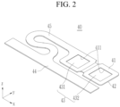
- FIG. 2 is a perspective view of a busbar, a flexible printed circuit, and a unit thin film portion of FIG. 1 before bending (e.g. before folding)
- FIG. 3 is a perspective view of the unit thin film portion of FIG. 2 during bending (e.g. during folding)
- FIG. 4 is a top plan view of the unit thin film portion of FIG. 2 in a completed state of bending (e.g. completed state of folding).
- the flexible printed circuit 40 is formed by providing a thin copper film between the inner surfaces of a pair of cover layers 41 and 42 attached to each other.
- the thin copper film is exposed in (a plurality of) unit thin film portions 43 (e.g. a first unit thin film portion 431 and a second unit thin film portion 432) through a plurality of openings 411 and 421 formed in the cover layers 41 and 42.
- the (first) cover layer 41 comprises a plurality of openings 411 formed therein
- the (second) cover layer 42 comprises plurality of openings 412 formed therein.
- Each of the unit thin film portions 43 comprise one opening in the cover layer 42 and the cover layer 43.
- the thin copper film which is disposed between the pair of cover layers 41 and 42, is accessible through the plurality of openings 411 and 421 in both cover layers 41 and 42.
- each of the unit thin film portions 43 comprises a part of the thin copper film accessible through the plurality of openings 411 and 421.
- FIG. 5 is a cross-sectional view taken along line V-V of the unit thin film portions of FIG. 4 bent (folded) over each other and arranged on a busbar
- FIG. 6 is a cross-sectional view taken along line V-V of the unit thin film portions of FIG. 5 welded on a busbar.
- the thin copper film and the cover layers 41 and 42 are bent (e.g. folded), and therefore the unit thin film portions 43 form multiple layers (e.g. multiple overlapping layers of unit thin film portions 43) and are welded to the busbar 30 made of aluminum.
- the multiple layers of unit thin film portions 43 i.e. the multiple overlapping layers of unit thin film portions 43 resulting from folding the thin copper film and the cover layers 41 and 42
- the flexible printed circuit 40 does not use nickel tabs, the flexible printed circuit 40 does not significantly deform and sag during movement. Therefore, the multiple layers of unit thin film portions 43 facilitates in-position junction of the flexible printed circuit 40 and the busbar 40.
- the unit thin film portion 43 has a thickness of 0.035 mm, the total thickness of the multiple layers is equal to 0.035 mm multiplied by the number of layers.
- the two-layer unit thin film portions 43 have a thickness of 0.07 mm, which is twice that of 0.035 mm.
- the two-layer unit thin portions 43 formed by bending have improved mechanical strength compared to the one-layer structure, it is possible to effectively prevent tearing, piercing during welding, and pinhole failure during movement and handling, for direct junction to the aluminum busbar 30.
- the flexible printed circuit 40 includes a main line portion 44 and a branch line portion 45.
- the main line portion 44 is disposed on the busbar holder 20 in the first direction (x-axis direction).
- the branch line portion 45 is connected to and protrudes from the main line portion 44 in the second direction (y-axis direction) intersecting the first direction and is disposed further in the first direction.
- the unit thin film portions 43 are parts joined to the busbar 30 and are connected to the branch line portion 45.
- the branch line unit 45 is disposed corresponding to the busbar 30.
- the unit thin film portions 43 include a first unit portion 431 and a second unit portion 432 that continuously extend along the first direction (x-axis direction).
- the first unit portion 431 and the second unit portion 432 are bent (e.g. folded) and overlapped with each other around a second direction bending axis BSy (folding axis) set in the second direction (y-axis direction).
- the first unit portion 431 includes a first plane portion F1 connected to a first inclined portion S1 at the first inclined angle ⁇ 1
- the second unit portion 432 includes a second plane portion F2 connected to a second inclined portion S2 at a second inclined angle ⁇ 2 that is greater than the first inclined angle ⁇ 1.
Landscapes
- Chemical & Material Sciences (AREA)
- Chemical Kinetics & Catalysis (AREA)
- Electrochemistry (AREA)
- General Chemical & Material Sciences (AREA)
- Engineering & Computer Science (AREA)
- Microelectronics & Electronic Packaging (AREA)
- Manufacturing & Machinery (AREA)
- Optics & Photonics (AREA)
- Physics & Mathematics (AREA)
- Plasma & Fusion (AREA)
- Mechanical Engineering (AREA)
- Connection Of Batteries Or Terminals (AREA)
- Battery Mounting, Suspending (AREA)
Abstract
Description
- The present disclosure relates to a rechargeable battery module, and more particularly, to a rechargeable battery module that connects a sensing portion of a flexible printed circuit (FPC) to a busbar.
- Unlike primary batteries, rechargeable batteries are batteries that can be repeatedly charged and discharged. Small-capacity rechargeable batteries are used in small, portable electronic devices such as mobile phones, laptop computers, and camcorders.
- High-capacity and high-density secondary batteries are used as power sources for driving motors in hybrid and electric vehicles or for energy storage. The rechargeable batteries may be used by forming a rechargeable battery module including a plurality of battery cells connected in series and/or parallel to drive a motor of, for example, a hybrid vehicle that requires relatively high energy density.
- The rechargeable battery module is equipped with a flexible printed circuit (FPC) that detects a voltage or current from the busbar and transmits a detection signal. The FPC sensing structure solders the FPC to a separate nickel tab (Ni-Tab) and welds the tab to an aluminum (Al) busbar.
- Nickel tabs (Ni- tab), however, are associated with increased costs because they require raw nickel, a soldering process to form junctions, a coating process to form an anticorrosion coating, and jigs for guides.
- Deformation (e.g., S deform) of the FPC causes sagging during movement due to the nickel tab. Such sagging in FPC can occur during the welding of the aluminum busbar and the nickel tab It is therefore difficult to form the in-position junction of the FPC and the nickel tab for the busbar.
- The present disclosure provides a rechargeable battery module capable of directly bonding of a flexible printed circuit (FPC) to a busbar. The present disclosure also provides a rechargeable battery module that enables in-position junction of the flexible printed circuit (FPC) to the busbar.
- A rechargeable battery module according to an embodiment of the present disclosure includes: a busbar holder covering a plurality of battery cells, a busbar disposed on the busbar holder to electrically connect the battery cells; and a flexible printed circuit (FPC) attached to the busbar for sending a signal and detecting a current in the busbar, wherein the flexible printed circuit includes a thin copper film attached between the inner surfaces of a pair of cover layers, wherein the thin copper film is exposed in (each of a plurality of) unit thin film portions through a plurality of openings formed in the pair of cover layers, the thin copper film and the pair of cover layers are bent, and the unit thin film portions are formed in multiple layers (e.g. the unit thin film portions form multiple layers) and welded to the busbar.
- The unit thin film portion has a thickness of 0.035 mm, and the total thickness of the multiple layers is equal to 0.035 mm multiplied by the number of layers.
- The flexible printed circuit includes: a main line portion disposed in a first direction on the busbar holder; and a branch line portion protruding from the main line portion in a second direction intersecting the first direction, and disposed further in the first direction. The unit thin film portions may be connected to the branch line portion.
- The branch line portion is attached to the busbar.
- In some embodiments, the rechargeable battery module has two unit thin film portions connected in the first direction.
- The unit thin film portions may include a first unit portion and a second unit portion continuously extending along the first direction, and the first unit portion and the second unit portion may be bent and overlapped with each other around a second direction bending axis set in the second direction.
- The first unit portion may include a first plane portion connected to a first inclined portion at a first inclined angle θ1, the second unit portion may include a second plane portion connected to a second inclined portion at a second inclined angle θ2 that is greater than the first inclined angle, and the first plane portion and the second plane portion may be connected in the second direction, sequentially stacked on the busbar, and welded to the busbar.
- In some embodiments, the rechargeable battery module has two unit thin film portions connected in the second direction.
- The unit thin film portions may include a first unit portion and a second unit portion continuously extending along the second direction, and the first unit portion and the second unit portion may be bent and overlapped with each other around a first direction bending axis set in the first direction.
- The first unit may include a first plane portion connected to the first inclined portion at a first inclination angle θ21, the second unit portion may include the second plane portion connected to the second inclined portion at a second inclined angle θ22 that is greater than the first inclined angle, and the first plane portion and the second plane portion may be connected in the first direction, sequentially stacked on the busbar, and welded to the busbar.
- In some embodiments, the rechargeable battery module has three unit thin film portions connected in the second direction.
- The unit thin film portions may include a first unit portion, a second unit portion and a third unit portion continuously extending along the second direction, wherein the first unit portion and the second unit portion may be bent and overlapped with each other around a first direction bending axis set in the first direction, and the second unit portion and the third unit portion may be bent and overlapped with each other around another first direction bending axis set in the first direction.
- The first unit portion may include the first plane portion connected to the first inclined portion at a first inclined angle θ31, the second unit portion may include the second plane portion connected to the second inclined portion at a second inclined angle θ32 that is greater than the first inclined angle, the third unit portion may include a third plane portion connected to a third inclined portion at a third inclined angle θ33 greater than the second inclined angle, and the first plane portion, the second plane portion, and the third plane portion may be connected in the second direction, sequentially stacked on the busbar, and welded to the busbar.
- In some embodiments, the rechargeable battery module has three unit thin film portions connected in the first direction.
- The unit thin film portions may include a first unit portion, a second unit portion and a third unit portion continuously extending along the first direction, wherein the first unit portion and the second unit portion may be bent and overlapped with each other around a second direction bending axis set in the second direction, and the second unit portion and the third unit portion may be bent and overlapped with each other around another second direction bending axis set in the second direction.
- The unit thin film portions may include a first unit portion, a second unit portion, a third unit portion and a fourth unit portion continuously extending along the first direction, wherein the first unit portion and the second unit portion may be bent and overlapped with each other around a second direction bending axis set in the second direction, the second unit portion and the third unit portion may be bent and overlapped with each other around another second direction bending axis set in the second direction, and the third unit portion and the fourth unit portion may be bent and overlapped with each other around the other second direction bending axis set in the second direction.
- In some embodiments, the rechargeable battery module has four unit thin film portions connected in the first direction and the second direction.
- The unit thin film portions may include a first unit portion and a second unit portion continuously extending along the first direction, and a third unit portion and a fourth unit portion continuously extending along the second direction to the first unit portion and the second unit portion, and continuously extending along the first direction.
- According to the above described embodiments of the rechargeable battery module, the thin copper film is exposed in the unit thin film portions through a plurality of openings formed in the cover layer, the thin copper film and the cover layer are bent (e.g. folded), and therefore the unit thin film portions form multiple layers and are welded to the busbar made of aluminum.
- The embodiments allow direct bonding a flexible printed circuit (FPC) and a busbar made of aluminum. Additionally, according to the variety of arrangements of the unit thin film portions in the embodiments, it is possible to bond the flexible printed circuit (FPC) to the busbar in the desired position.
- Another aspect of the present disclosure relates to a flexible printed circuit for a rechargeable battery module as described above, configured to send a signal and to detect a current. The flexible printed circuit comprises a thin copper film attached between inner surfaces of a pair of cover layers, the thin copper film being exposed in unit thin film portions through a plurality of openings formed in the pair of cover layers, wherein the thin copper film and the pair of cover layers are foldable (e.g. bendable), and the unit thin film portions are configured to form multiple overlapping layers.
-
-
FIG. 1 is a partial cross-sectional view of a rechargeable battery module according to a first embodiment of the present disclosure. -
FIG. 2 is a perspective view of a busbar, a flexible printed circuit, and a unit thin film portion ofFIG. 1 before bending (e.g. folding). -
FIG. 3 is a perspective view of the unit thin film portion ofFIG. 2 during bending (e.g. folding). -
FIG. 4 is a top plan view of the unit thin film portion ofFIG. 2 in a completed state of bending (e.g. folding). -
FIG. 5 is a cross-sectional view taken along line V-V of the unit thin film portions ofFIG. 4 bent (folded) over each other and arranged on a busbar. -
FIG. 6 is a cross-sectional view taken along line V-V of the unit thin film portions ofFIG. 5 welded on a busbar. -
FIG. 7 is a top plan view of the busbar, flexible printed circuit, and unit thin film portion in the rechargeable battery module according to the second embodiment of the present disclosure before bending (e.g. folding). -
FIG. 8 is a top plan view of the unit thin film portion ofFIG. 7 in a completed state of bending (e.g. folding). -
FIG. 9 is a cross-sectional view taken along line IX-IX of the unit thin film portions ofFIG. 8 bent (folded) over each other and arranged on a busbar. -
FIG. 10 is a cross-sectional view taken along line IX-IX of the unit thin film portions ofFIG. 8 welded on a busbar. -
FIG. 11 is a perspective view of the busbar, flexible printed circuit, and unit thin film portion in the rechargeable battery module according to the third embodiment of the present disclosure before bending (e.g. folding). -
FIG. 12 is a perspective view of the unit thin film portion ofFIG. 11 in a completed state of bending (e.g. folding). -
FIG. 13 is a cross-sectional view taken along line XIII-XIII of the unit thin film portions ofFIG. 12 bent (folded) over each other and arranged on a busbar. -
FIG. 14 is a cross-sectional view taken along line XIII-XIII of the unit thin film portions ofFIG. 12 welded on a busbar. -
FIG. 15 is a top plan view of the busbar, flexible printed circuit, and unit thin film portion in the rechargeable battery module according to the fourth embodiment of the present disclosure before bending (e.g. folding). -
FIG. 16 is a perspective view of the primary and secondary bending states of the flexible printed circuit and the unit thin film portion in the rechargeable battery module according to the fifth embodiment of the present disclosure. -
FIG. 17 is a perspective view of the unit thin film portion ofFIG. 16 in the tertiary bending state, which corresponds to a complete state of bending (e.g. folding). -
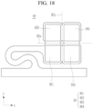
FIG. 18 is a top plan view of the busbar, flexible printed circuit, and unit thin film portion in the rechargeable battery module according to the sixth embodiment of the present disclosure before bending (e.g. folding). - Hereinafter, the present disclosure will be described more fully with reference to the accompanying drawings, in which exemplary embodiments of the invention are shown. As those skilled in the art will realize, the described embodiments may be modified in various different ways, all without departing from the scope of the present disclosure. The drawings and description are to be regarded as illustrative in nature and not restrictive. Like reference numerals designate like elements throughout the specification.
-
FIG. 1 is a partial cross-sectional view of a rechargeable battery module according to a first embodiment of the present disclosure. Referring toFIG. 1 , the rechargeable battery module of the first embodiment includes a plurality ofbattery cells 10 formed of rechargeable batteries, abusbar holder 20, abusbar 30, and a flexible printed circuit (FPC) 40. - The rechargeable battery module of the first embodiment may have module frames of various structures, but detailed description of this configuration will be omitted and will be described as an example. A plurality of
battery cells 10 are formed as rechargeable batteries and are stacked in a first direction (x-axis direction). - A pair of end plates is disposed on both ends of the stacked
battery cells 10 in the first direction to constrain thebattery cells 10 in the first direction (x-axis direction). A pair of side plates are disposed on both sides of the second direction (y-axis direction) of thebattery cells 10 intersecting the first direction, and are connected to a pair of end plates to constrain thebattery cells 10 in the second direction. - The
battery cells 10 may be disposed in one or two rows. When disposed in two rows, an additional center plate may be disposed between a pair of side plates. The center plate is disposed in the first direction between the two rows ofbattery cells 10 to constrain thebattery cells 10 in the second direction on both sides. - The
busbar holder 20 may include abusbar support 25 for connecting and insulating the electrode terminals (not shown) of thebattery cells 10, and a vent portion for discharging vent gas of the battery cells 10 (not shown). - The
busbar support 25 exposes the electrode terminals in the third direction (height of the battery cell, z-axis direction) to cover the other portions of thebattery cells 10 while supporting thebusbar 30 that connects the electrode terminals in series or parallel. The third direction (height of the battery cell, z-axis direction) intersects the first direction (thickness of the battery cell, x-axis direction) and the second direction (length of the battery cell, y-axis direction). - The flexible printed circuit (FPC) 40 is configured to be attached to the
busbar 30, to detect a current flowing in thebusbar 30 that electrically connects thebattery cells 10, and to send a detection signal to the battery management system (BMS). - The rechargeable battery module of the first embodiment may further include a
top cover 70. Thetop cover 70 is disposed on thebusbar 30, and is coupled to thebusbar holder 20 from the outside to cover a plurality of busbars (not shown) and thebusbar holder 20. -
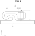
FIG. 2 is a perspective view of a busbar, a flexible printed circuit, and a unit thin film portion ofFIG. 1 before bending (e.g. before folding),FIG. 3 is a perspective view of the unit thin film portion ofFIG. 2 during bending (e.g. during folding), andFIG. 4 is a top plan view of the unit thin film portion ofFIG. 2 in a completed state of bending (e.g. completed state of folding). - Referring to
FIGS. 2 to 4 , the flexible printedcircuit 40 is formed by providing a thin copper film between the inner surfaces of a pair of cover layers 41 and 42 attached to each other. The thin copper film is exposed in (a plurality of) unit thin film portions 43 (e.g. a first unitthin film portion 431 and a second unit thin film portion 432) through a plurality ofopenings cover layer 41 comprises a plurality ofopenings 411 formed therein and the (second)cover layer 42 comprises plurality of openings 412 formed therein. Each of the unitthin film portions 43 comprise one opening in thecover layer 42 and thecover layer 43. The thin copper film, which is disposed between the pair of cover layers 41 and 42, is accessible through the plurality ofopenings layers thin film portions 43 comprises a part of the thin copper film accessible through the plurality ofopenings -
FIG. 5 is a cross-sectional view taken along line V-V of the unit thin film portions ofFIG. 4 bent (folded) over each other and arranged on a busbar, andFIG. 6 is a cross-sectional view taken along line V-V of the unit thin film portions ofFIG. 5 welded on a busbar. - Referring to
FIGS. 5 and6 , the thin copper film and the cover layers 41 and 42 are bent (e.g. folded), and therefore the unitthin film portions 43 form multiple layers (e.g. multiple overlapping layers of unit thin film portions 43) and are welded to thebusbar 30 made of aluminum. In this way, the multiple layers of unit thin film portions 43 (i.e. the multiple overlapping layers of unitthin film portions 43 resulting from folding the thin copper film and the cover layers 41 and 42) enable and strengthen the welding between dissimilar materials such as copper and aluminum. - Since the flexible printed
circuit 40 does not use nickel tabs, the flexible printedcircuit 40 does not significantly deform and sag during movement. Therefore, the multiple layers of unitthin film portions 43 facilitates in-position junction of the flexible printedcircuit 40 and thebusbar 40. - Since the unit
thin film portion 43 has a thickness of 0.035 mm, the total thickness of the multiple layers is equal to 0.035 mm multiplied by the number of layers. - In the first embodiment, the two-layer unit
thin film portions 43 have a thickness of 0.07 mm, which is twice that of 0.035 mm. - Since the two-layer unit
thin portions 43 formed by bending (e.g. folding) have improved mechanical strength compared to the one-layer structure, it is possible to effectively prevent tearing, piercing during welding, and pinhole failure during movement and handling, for direct junction to thealuminum busbar 30. - Referring again to
FIGS. 2 to 4 , the flexible printedcircuit 40 includes amain line portion 44 and abranch line portion 45. Themain line portion 44 is disposed on thebusbar holder 20 in the first direction (x-axis direction). Thebranch line portion 45 is connected to and protrudes from themain line portion 44 in the second direction (y-axis direction) intersecting the first direction and is disposed further in the first direction. - The unit
thin film portions 43 are parts joined to thebusbar 30 and are connected to thebranch line portion 45. Thebranch line unit 45 is disposed corresponding to thebusbar 30. In the first embodiment, there are two unitthin film portions 43 that are connected in the first direction (x-axis direction). - The unit
thin film portions 43 include afirst unit portion 431 and asecond unit portion 432 that continuously extend along the first direction (x-axis direction). Thefirst unit portion 431 and thesecond unit portion 432 are bent (e.g. folded) and overlapped with each other around a second direction bending axis BSy (folding axis) set in the second direction (y-axis direction). - Referring again to
FIGS. 5 and6 , in the welded state, thefirst unit portion 431 includes a first plane portion F1 connected to a first inclined portion S1 at the first inclined angle θ1, and thesecond unit portion 432 includes a second plane portion F2 connected to a second inclined portion S2 at a second inclined angle θ2 that is greater than the first inclined angle θ1. - The first plane portion F1 and the second plane portion F2 are connected in the second direction (y-axis direction), are sequentially stacked on the
busbar 30, and are welded to thebusbar 30. Compared to a one-layer structure, the first plane portion F1 and the second plane portion F2 forming a two-layer structure may effectively prevent piercing and pinhole defects during welding. And the current signal of thebus bar 30 is transmitted to thebranch line portion 45 and themain line portion 44 via the first inclined portion S1 and the second inclined portion S2 through the welded first plane portion F1 and the second plane portion F2. - In the flexible printed
circuit 40 of the first embodiment, compared to themain line portion 44, thebranch line portion 45 and the unitthin film portions 43 generate scrap on both sides of the x-axis direction. The flexible printedcircuit 40 of the first embodiment allows the formation of unitthin film portions 43 while minimizing the generation of such scrap. - Hereinafter, various embodiments of the present disclosure will be described. Compared to the first embodiment and the previously described embodiments, descriptions of the same components will be omitted and descriptions of different components will be described.
-
FIG. 7 is a top plan view of the busbar, flexible printed circuit, and unit thin film portion in the rechargeable battery module according to a second embodiment of the present disclosure before bending (e.g. folding), andFIG. 8 is a top plan view of the unit thin film portion ofFIG. 7 in a completed state of bending (e.g. folding). Referring toFIGS. 7 and8 , in the second embodiment, there are two unit thin film portions of a flexible printedcircuit 50 that are connected in the second direction (y-axis direction). -
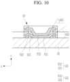
FIG. 9 is a cross-sectional view taken along line IX-IX of the unit thin film portions ofFIG. 8 bent (folded) over each other and arranged on a busbar, andFIG. 10 is a cross-sectional view taken along line IX-IX of the unit thin film portions ofFIG. 8 welded on a busbar. - Referring to
FIGS. 7 to 10 , unitthin film portions 53 include afirst unit portion 531 and asecond unit portion 532 continuously extending along the second direction (y-axis direction). Thefirst unit portion 531 and thesecond unit portion 532 are bent and overlapped with each other around a first direction bending axis BSx set in the first direction (x-axis direction). - In a welded state, the
first unit portion 531 includes a first plane portion F21 connected to a first inclined portion S21 at the first inclined angle θ21, and thesecond unit portion 532 includes a second plane portion F22 connected to a second inclined portion S22 at a second inclined angle θ22 that is greater than the first inclined angle θ21. - The first plane portion F21 and the second plane portion F22 are connected in the first direction (x-axis direction), are sequentially stacked on the
busbar 30, and are welded to thebusbar 30. Compared to a one-layer structure, the first plane portion F21 and the second plane portion F22 forming a two-layer structure may effectively prevent piercing and pinhole defects during welding. And the current signal of thebus bar 30 is transmitted to abranch line portion 55 and amain line portion 54 via the first inclined portion S21 and the second inclined portion S22 through the welded first plane portion F21 and the second plane portion F22. - In the flexible printed
circuit 50 of the second embodiment, compared to themain line portion 54, thebranch line portion 55 and the unitthin film portions 53 generate scrap on both sides of the x-axis direction. The flexible printedcircuit 50 of the second embodiment generates more scrap on both sides of the x-axis direction of thesecond unit portion 532 than the flexible printedcircuit 40 of the first embodiment in forming the unitthin film portions 53. -
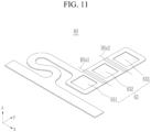
FIG. 11 is a perspective view of the busbar, flexible printed circuit, and unit thin film portion in the rechargeable battery module according to a third embodiment of the present disclosure before bending (e.g. folding), andFIG. 12 is a perspective view of the unit thin film portion ofFIG. 11 in a completed state of bending (e.g. folding). Referring toFIGS. 11 and12 , in the third embodiment, the unit thin film portions of a flexible printedcircuit 60 are formed of three and connected in the second direction (y-axis direction). -
FIG. 13 is a cross-sectional view taken along line XIII-XIII of the unit thin film portions ofFIG. 12 bent (folded) over each other and arranged on a busbar, andFIG. 14 is a cross-sectional view taken along line XIII-XIII of the unit thin film portions ofFIG. 12 welded on a busbar. - Referring to
FIGS. 11 to 14 , unitthin film portions 63 include afirst unit portion 631, asecond unit portion 632, and athird unit portion 633. Thefirst unit portion 631 and thesecond unit portion 632 are bent and overlapped with each other around a first direction bending axis BSx1 set in the first direction (x-axis direction). Thesecond unit portion 632 and thethird unit portion 633 are bent and overlapped with each other around another first direction bending axis BSx2 set in the first direction (x-axis direction). - In a welded state, the
first unit portion 631 includes a first plane portion F31 connected to a first inclined portion S31 at a first inclined angle θ31, thesecond unit portion 632 includes a second plane portion F32 connected to a second inclined portion S32 at a second inclined angle θ32 that is greater than the first inclined angle θ31, and thethird unit portion 633 includes a third plane portion F33 connected to a third inclined portion S33 at a third inclined angle θ33 that is greater than the second inclined angle θ32. - The first plane portion F31, the second plane portion F32, and the third plane portion F33 are connected in the second direction (y-axis direction), are sequentially stacked on the
busbar 30, and are welded to thebusbar 30. Compared to a one-layer structure or a two-layer structure, the first plane portion F31, the second plane portion F32 and the third plane portion F33 forming a three-layer structure may effectively prevent piercing and pinhole defects during welding. And the current signal of thebus bar 30 is transmitted to thebranch line portion 55 and amain line portion 54 via the first inclined portion S31, the second inclined portion S32, and the third inclined portion S33 through the welded first plane portion F31, the second plane portion F32, and the third plane portion F33. - In the flexible printed
circuit 60 of the third embodiment, the unitthin film portions 63 generate scrap on both sides of the x-axis direction. The flexible printedcircuit 60 of the third embodiment generates more scrap on both sides of the x-axis direction of thesecond unit portion 632 and thethird unit portion 633 than the flexible printedcircuit 40 of the first embodiment in forming the unitthin film portions 63. -
FIG. 15 is a top plan view of the busbar, flexible printed circuit, and unit thin film portion in the rechargeable battery module according to a fourth embodiment of the present disclosure before bending (e.g. folding). Referring toFIG. 15 , in the fourth embodiment, the unit thin film portions of a flexible printedcircuit 80 are formed of three and connected in the first direction (x-axis direction). - Unit
thin film portions 83 include afirst unit portion 831, asecond unit portion 832 and athird unit portion 833 that continuously extend along the first direction (x-axis direction). Thefirst unit portion 831 and thesecond unit portion 832 are bent and overlapped with each other around a second direction bending axis BSy1 set in the second direction (y-axis direction). Thesecond unit portion 832 and thethird unit portion 833 are bent and overlapped with each other around another second direction bending axis BSy2 set in the second direction (y-axis direction). - Compared to a one-layer structure or a two-layer structure, the
first plane portion 831, thesecond plane portion 832 and thethird plane portion 833 forming a three-layer structure may effectively prevent piercing and pinhole defects during welding. - In the flexible printed
circuit 80 of the fourth embodiment, the unitthin film portions 83 generate scrap on both sides of the x-axis direction. The flexible printedcircuit 80 of the fourth embodiment, in forming theunit film portions 83, compared to the flexible printedcircuit 40 of the first embodiment, generates less scrap on both sides in the x-axis direction because the flexible printedcircuit 80 further includes thesecond unit portion 832 and thethird unit portion 833. -
FIG. 16 is a perspective view of the primary and secondary bending states of the flexible printed circuit and the unit thin film portion in the rechargeable battery module according to a fifth embodiment of the present disclosure, andFIG. 17 is a perspective view of the unit thin film portion ofFIG. 16 in the tertiary bending state of bending, which corresponds to a complete state of bending (e.g. folding). Referring toFIGS. 16 and17 , in the fifth embodiment, the unit thin film portions of a flexible printedcircuit 90 are formed of four and connected in the first direction (x-axis direction). - Unit
thin film portions 93 include afirst unit portion 931, asecond unit portion 932, athird unit portion 933 and afourth unit portion 934 that continuously extend along the first direction (x-axis direction). Thefirst unit portion 931 and thesecond unit portion 932 are bent and overlapped with each other around the second direction bending axis BSy1 set in the second direction (y-axis direction). Thesecond unit portion 932 and thethird unit portion 933 are bent and overlapped with each other around another second direction bending axis BSy2 set in the second direction (y-axis direction). Thethird unit portion 933 and thefourth unit portion 934 are bent and overlapped with each other around the other second direction bending axis BSy3 set in the second direction (y-axis direction). - Compared to a one-layer structure, a two-layer structure or a three-layer structure, the
first plane portion 931, thesecond plane portion 932, thethird plane portion 933 and thefourth unit portion 934 forming a four-layer structure may effectively prevent piercing and pinhole defects during welding. - In the flexible printed
circuit 90 of the fifth embodiment, the unitthin film portions 93 generate scrap on both sides of the x-axis direction. The flexible printedcircuit 90 of the fifth embodiment, in forming theunit film portions 93, compared to the flexible printedcircuit 40 of the first embodiment, generates less scrap on both sides in the x-axis direction because the flexible printedcircuit 90 further includes thesecond unit portion 932, thethird unit portion 933 and thefourth unit portion 934. -
FIG. 18 is a top plan view of the busbar, flexible printed circuit, and unit thin film portion in the rechargeable battery module according to a sixth embodiment of the present disclosure before bending (e.g. folding). Referring toFIG. 18 , in the sixth embodiment, the unit thin film portions of a flexible printedcircuit 98 are formed of four and connected in the first direction (x-axis direction) and in the second direction (y-axis direction). - Unit
thin film portions 96 include afirst unit portion 961 and asecond unit portion 962 continuously extending along the first direction (x-axis direction), and athird unit portion 963 and afourth unit portion 964 continuously extending along the second direction (y-axis direction) to thefirst unit portion 961 and thesecond unit portion 962, and continuously extending along the first direction (x-axis direction). - The
third unit portion 963 and thefourth unit portion 964 are bent around one first direction bending axis BSx set in the first direction (x-axis direction), and are each overlapped with thefirst unit portion 961 and thesecond unit portion 962. Thefourth unit portion 964 and thesecond unit portion 962 overlapped with each other are bent around the second direction bending axis BSy set in the second direction (y-axis direction), and are overlapped with thefirst unit portion 961 and thethird unit portion 963, which are overlapped with each other. - Compared to a one-layer structure, a two-layer structure, or a three-layer structure, the
first plane portion 961, thesecond plane portion 962, thethird plane portion 963, and thefourth unit portion 964 forming a four-layer structure may effectively prevent piercing and pinhole defects during welding. - In the flexible printed
circuit 98 of the sixth embodiment, the unitthin film portions 96 generate scrap on both sides of the x-axis direction. The flexible printedcircuit 98 of the sixth embodiment, in forming theunit film portions 96, compared to the flexible printedcircuit 40 of the first embodiment, generates less scrap on both sides in the x-axis direction because the flexible printedcircuit 98 further includes thesecond unit portion 962, and generates more scrap on both sides in the x-axis direction because the flexible printedcircuit 98 further includes thethird unit portion 963 and thefourth unit portion 964. - While this disclosure has been described in connection with what is presently considered to be practical embodiments, it is to be understood that the disclosure is not limited to the disclosed embodiments, but, on the contrary, is intended to cover various modifications and equivalent arrangements included within the scope of the appended claims.
-
- 10: Battery cell
- 20: Busbar holder
- 25: Busbar support
- 30: Busbar
- 40, 50, 60, 80, 90, 98: Flexible printed circuit (FPC)
- 41, 42: Cover layer
- 43, 53, 63, 83, 93, 96: Unit thin film portion
- 44, 54: Main line
- 45, 55: Branch line
- 70: Top cover
- 411, 421: Opening
- 431, 531, 631, 831, 931, 961: First unit portion
- 432, 532, 632, 832, 932, 962: Second unit portion
- 633, 833, 933, 963: Third unit portion
- 934, 964: Fourth unit portion
- BSx, BSx1, BSx2: First direction bending axis
- BSy, BSy1, BSy2, BSy3: Second direction bending axis
- F1, F21, F31: First plane portion
- F2, F22, F32: Second plane portion
- F33: Third plane portion
- S1, S21, S31: First inclined portion
- S2, S22, S32: Second inclined section
- S33: Third inclined portion
- θ1, θ21, θ31: First inclined angle
- θ2, θ22, θ32: Second inclined angle
- θ33: Third inclined angle
Claims (15)
- A rechargeable battery module comprising:a busbar holder (20) covering a plurality of battery cells (10);a busbar disposed on the busbar holder (20) to electrically connect the battery cells (10); anda flexible printed circuit (40, 50, 60, 80, 90, 98) attached to the busbar, the flexible printed circuit (40, 50, 60, 80, 90, 98) being configured to send a signal and to detect a current in the busbar, the flexible printed circuit (40, 50, 60, 80, 90, 98) including a thin copper film attached between inner surfaces of a pair of cover layers (41, 42),wherein the thin copper film is exposed in unit thin film portions (43, 53, 63, 83, 93, 96) through a plurality of openings (411, 421) formed in the pair of cover layers (41, 42),wherein the thin copper film and the pair of cover layers (41, 42) are bent, andwherein the unit thin film portions (43, 53, 63, 83, 93, 96) form multiple layers and are welded to the busbar.
- The rechargeable battery module of claim 1, wherein each unit thin film portion has a thickness of 0.035 mm, and
wherein a thickness of the multiple layers is equal to 0.035 mm multiplied by the number of layers. - The rechargeable battery module of one of claims 1 or 2, wherein the flexible printed circuit (40, 50, 60, 80, 90, 98) comprises:a main line portion (44, 54) disposed in a first direction on the busbar holder (20); anda branch line portion (45, 55) protruding from the main line portion (44, 54) in a second direction intersecting the first direction, and disposed further in the first direction, andwherein the unit thin film portions (43, 53) are connected to the branch line portion (45, 55).
- The rechargeable battery module of claim 3, wherein the branch line portion (55) is attached to the busbar.
- The rechargeable battery module one of claims 3 or 4, wherein the rechargeable battery module has two unit thin film portions (43) connected in the first direction,wherein the unit thin film portions (43) comprise a first unit portion (431) and a second unit portion (432) continuously extending along the first direction, andwherein the first unit portion (431) and the second unit portion (432) are bent around a second direction bending axis set in the second direction such that the first unit portion (431) and the second unit portion (432) overlap with each other.
- The rechargeable battery module of claim 5, wherein the first unit portion (431) comprises a first plane portion (F1) connected to a first inclined portion (S1) at a first inclined angle θ1,wherein the second unit portion (432) comprises a second plane portion (F2) connected to a second inclined portion (S2) at a second inclined angle θ2 that is greater than the first inclined angle θ1, andwherein the first plane portion (F1) and the second plane portion (F2) are connected in the second direction, are sequentially stacked on the busbar, and are welded to the busbar.
- The rechargeable battery module of one of claims 3 or 4, wherein the rechargeable battery module comprise two of the unit thin film portions (53, 63) connected in the second direction,wherein the unit thin film portions (53, 63) comprise a first unit portion (531, 631) and a second unit portion (532, 632) continuously extending along the second direction, andwherein the first unit portion (531, 631) and the second unit portion (532, 632) are bent around a first direction bending axis set in the first direction such that the first unit portion (531, 631) and the second unit portion (532, 632) overlap each other.
- The rechargeable battery module of claim 7, wherein the first unit portion (531, 631) comprises a first plane portion (F21, F31) connected to a first inclined portion (S21, S31) at a first inclined angle θ21,wherein the second unit portion (532, 632) comprises a second plane portion (F22, F32) connected to a second inclined portion (S22, S32) at a second inclined angle θ22 that is greater than the first inclined angle θ21, andwherein the first plane portion (F21, F31) and the second plane portion (F22, F32) are connected in the first direction, are sequentially stacked on the busbar, and are welded to the busbar.
- The rechargeable battery module of one of claims 3 or 4, wherein the rechargeable battery module has three of the unit thin film portions (63) connected in the second direction,wherein the unit thin film portions (63) comprise a first unit portion (631), a second unit portion (632), and a third unit portion (633) continuously extending along the second direction,wherein the first unit portion (631) and the second unit portion (632) are bent around a first direction bending axis set in the first direction such that the first unit portion (631) and the second unit portion (632) overlap with each other, andwherein the second unit portion (632) and the third unit portion (633) are bent around another first direction bending axis set in the first direction such that the second unit portion (632) and the third unit portion (633) overlap with each other.
- The rechargeable battery module of claim 9, wherein the first unit portion (631) comprises a first plane portion (F31) connected to a first inclined portion (S31) at a first inclined angle θ31,wherein the second unit portion (632) comprises a second plane portion (F32) connected to a second inclined portion (S32) at a second inclined angle θ32 that is greater than the first inclined angle θ31,wherein the third unit portion (633) comprises a third plane portion (F33) connected to a third inclined portion (S33) at a third inclined angle θ33 that is greater than the second inclined angle θ32, andwherein the first plane portion (F31), the second plane portion (F32), and the third plane portion (F33) are connected in the second direction, are sequentially stacked on the busbar, and are welded to the busbar.
- The rechargeable battery module of one of claims 3 or 4, wherein the rechargeable battery module has three of the unit thin film portions connected in the first direction,wherein the unit thin film portions comprise a first unit portion (831), a second unit portion (832), and a third unit portion (833) continuously extending along the first direction,wherein the first unit portion (831) and the second unit portion (832) are bent around a second direction bending axis set in the second direction such that the first unit portion (831) and the second unit portion (832) overlap with each other, andwherein the second unit portion (832) and the third unit portion (833) are bent around another second direction bending axis set in the second direction such that the second unit portion (832) and the third unit portion (833) overlap with each other.
- The rechargeable battery module of one of claims 3 or 4, wherein the unit thin film portions (93) comprise a first unit portion (931), a second unit portion (932), a third unit portion (933), and a fourth unit portion (934) continuously extending along the first direction,wherein the first unit portion (931) and the second unit portion (932) are bent around a second direction bending axis set in the second direction such that the first unit portion (931) and the second unit portion (932) overlap with each other,wherein the second unit portion (932) and the third unit portion (933) are bent around another second direction bending axis set in the second direction such that the second unit portion (932) and the third unit portion (933) overlap with each other, andwherein the third unit portion (933) and the fourth unit portion (934) are bent around the other second direction bending axis set in the second direction such that the third unit portion (933) and the fourth unit portion (934) overlap with each other.
- The rechargeable battery module of one of claims 3 or 4, wherein the rechargeable battery module has four of the unit thin film portions connected in the first direction and the second direction.
- The rechargeable battery module of claim 13,wherein the unit thin film portions comprise a first unit portion (961) and a second unit portion (962) continuously extending along the first direction; andwherein the unit film portions comprise a third unit portion (963) and a fourth unit portion (964) continuously extending along the second direction, connected to the first unit portion (961) and the second unit portion (962), and continuously extending along the first direction.
- A flexible printed circuit (40, 50, 60, 80, 90, 98) for a rechargeable battery module, configured to send a signal and to detect a current, the flexible printed circuit (40, 50, 60, 80, 90, 98) comprising:a thin copper film attached between inner surfaces of a pair of cover layers (41, 42),the thin copper film being exposed in unit thin film portions (43, 53, 63, 83, 93, 96) through a plurality of openings (411, 421) formed in the pair of cover layers (41, 42),wherein the thin copper film and the pair of cover layers (41, 42) are foldable, andthe unit thin film portions (43, 53, 63, 83, 93, 96) configured to form multiple overlapping layers.
Applications Claiming Priority (1)
| Application Number | Priority Date | Filing Date | Title |
|---|---|---|---|
| KR1020230095514A KR20250014845A (en) | 2023-07-21 | 2023-07-21 | Rechargeable battery module |
Publications (1)
| Publication Number | Publication Date |
|---|---|
| EP4496107A1 true EP4496107A1 (en) | 2025-01-22 |
Family
ID=91950200
Family Applications (1)
| Application Number | Title | Priority Date | Filing Date |
|---|---|---|---|
| EP24188502.9A Pending EP4496107A1 (en) | 2023-07-21 | 2024-07-15 | Rechargeable battery module |
Country Status (4)
| Country | Link |
|---|---|
| US (1) | US20250030129A1 (en) |
| EP (1) | EP4496107A1 (en) |
| KR (1) | KR20250014845A (en) |
| CN (1) | CN119340623A (en) |
Cited By (1)
| Publication number | Priority date | Publication date | Assignee | Title |
|---|---|---|---|---|
| EP4586362A3 (en) * | 2024-01-05 | 2025-11-05 | Samsung Sdi Co., Ltd. | Rechargeable battery module |
Citations (2)
| Publication number | Priority date | Publication date | Assignee | Title |
|---|---|---|---|---|
| US4851613A (en) * | 1988-06-08 | 1989-07-25 | Flex Technology, Inc. | Flexible circuit laminate for surface mount devices |
| WO2018124751A1 (en) * | 2016-12-27 | 2018-07-05 | 주식회사 유라코퍼레이션 | Flexible circuit board and frame assembly including same |
-
2023
- 2023-07-21 KR KR1020230095514A patent/KR20250014845A/en active Pending
-
2024
- 2024-05-01 US US18/651,778 patent/US20250030129A1/en active Pending
- 2024-07-08 CN CN202410903201.6A patent/CN119340623A/en active Pending
- 2024-07-15 EP EP24188502.9A patent/EP4496107A1/en active Pending
Patent Citations (2)
| Publication number | Priority date | Publication date | Assignee | Title |
|---|---|---|---|---|
| US4851613A (en) * | 1988-06-08 | 1989-07-25 | Flex Technology, Inc. | Flexible circuit laminate for surface mount devices |
| WO2018124751A1 (en) * | 2016-12-27 | 2018-07-05 | 주식회사 유라코퍼레이션 | Flexible circuit board and frame assembly including same |
Cited By (1)
| Publication number | Priority date | Publication date | Assignee | Title |
|---|---|---|---|---|
| EP4586362A3 (en) * | 2024-01-05 | 2025-11-05 | Samsung Sdi Co., Ltd. | Rechargeable battery module |
Also Published As
| Publication number | Publication date |
|---|---|
| US20250030129A1 (en) | 2025-01-23 |
| KR20250014845A (en) | 2025-02-03 |
| CN119340623A (en) | 2025-01-21 |
Similar Documents
| Publication | Publication Date | Title |
|---|---|---|
| KR102735192B1 (en) | Battery pack | |
| JP6869355B2 (en) | Flexible circuit board and frame assembly containing it | |
| KR101189430B1 (en) | Battery module and manufacturing method of battery module | |
| US12283720B2 (en) | Bus bar, and battery module using same | |
| JP7596525B2 (en) | Battery module and manufacturing method thereof | |
| JP2021511633A (en) | Battery module including rechargeable battery and busbar | |
| JP7291312B2 (en) | A battery module that uses a non-welded structure as the connection structure between the busbar and the voltage sensing member | |
| JP2020513661A (en) | Battery module | |
| KR20170032098A (en) | Battery module and protecting structure applied for the same | |
| JP7718779B2 (en) | Battery module and battery pack including same | |
| KR102543155B1 (en) | Busbar frame and battery module having the same | |
| JP7663553B2 (en) | Voltage detection wires and voltage detection wire modules | |
| EP4496107A1 (en) | Rechargeable battery module | |
| KR102526844B1 (en) | Busbar frame and battery module having the same | |
| JP2024084722A (en) | Secondary Battery Module | |
| JP2006164863A (en) | Flat battery pack and manufacturing method thereof | |
| KR102523946B1 (en) | Busbar frame and battery module having the same | |
| KR20110070029A (en) | Secondary battery and electrode assembly manufacturing method thereof | |
| US20260088458A1 (en) | Battery Apparatus and Manufacturing Apparatus of Battery Apparatus and Manufacturing Method of Battery Apparatus | |
| US20240213632A1 (en) | Cell laminate | |
| KR102898511B1 (en) | Battery Cell Without Welding Process and Battery Pack Having The Same | |
| JP2025163459A (en) | Power storage device | |
| KR20260055640A (en) | Electrode assembly and secondary battery comprising the same | |
| KR20260004015A (en) | Battery pack and device including the same | |
| JP2025096922A (en) | Bus bar and battery module using said bus bar |
Legal Events
| Date | Code | Title | Description |
|---|---|---|---|
| PUAI | Public reference made under article 153(3) epc to a published international application that has entered the european phase |
Free format text: ORIGINAL CODE: 0009012 |
|
| STAA | Information on the status of an ep patent application or granted ep patent |
Free format text: STATUS: REQUEST FOR EXAMINATION WAS MADE |
|
| 17P | Request for examination filed |
Effective date: 20240715 |
|
| AK | Designated contracting states |
Kind code of ref document: A1 Designated state(s): AL AT BE BG CH CY CZ DE DK EE ES FI FR GB GR HR HU IE IS IT LI LT LU LV MC ME MK MT NL NO PL PT RO RS SE SI SK SM TR |
|
| GRAP | Despatch of communication of intention to grant a patent |
Free format text: ORIGINAL CODE: EPIDOSNIGR1 |
|
| STAA | Information on the status of an ep patent application or granted ep patent |
Free format text: STATUS: GRANT OF PATENT IS INTENDED |
|
| INTG | Intention to grant announced |
Effective date: 20251223 |
|
| GRAS | Grant fee paid |
Free format text: ORIGINAL CODE: EPIDOSNIGR3 |
|
| GRAA | (expected) grant |
Free format text: ORIGINAL CODE: 0009210 |
|
| STAA | Information on the status of an ep patent application or granted ep patent |
Free format text: STATUS: THE PATENT HAS BEEN GRANTED |