EP4496045A2 - Festoxidbrennstoffzelle und festoxidbrennstoffzellenstapel - Google Patents
Festoxidbrennstoffzelle und festoxidbrennstoffzellenstapel Download PDFInfo
- Publication number
- EP4496045A2 EP4496045A2 EP24188580.5A EP24188580A EP4496045A2 EP 4496045 A2 EP4496045 A2 EP 4496045A2 EP 24188580 A EP24188580 A EP 24188580A EP 4496045 A2 EP4496045 A2 EP 4496045A2
- Authority
- EP
- European Patent Office
- Prior art keywords
- oxide
- hydrogen electrode
- metal
- particle
- electrode layer
- Prior art date
- Legal status (The legal status is an assumption and is not a legal conclusion. Google has not performed a legal analysis and makes no representation as to the accuracy of the status listed.)
- Pending
Links
- 239000007787 solid Substances 0.000 title claims abstract description 70
- 239000000446 fuel Substances 0.000 title description 5
- UFHFLCQGNIYNRP-UHFFFAOYSA-N Hydrogen Chemical compound [H][H] UFHFLCQGNIYNRP-UHFFFAOYSA-N 0.000 claims abstract description 214
- 239000001257 hydrogen Substances 0.000 claims abstract description 214
- 229910052739 hydrogen Inorganic materials 0.000 claims abstract description 214
- 239000002245 particle Substances 0.000 claims abstract description 79
- 239000002923 metal particle Substances 0.000 claims abstract description 53
- 229910044991 metal oxide Inorganic materials 0.000 claims abstract description 50
- 150000004706 metal oxides Chemical class 0.000 claims abstract description 50
- 239000003792 electrolyte Substances 0.000 claims abstract description 39
- 239000001301 oxygen Substances 0.000 claims abstract description 37
- 229910052760 oxygen Inorganic materials 0.000 claims abstract description 37
- QVGXLLKOCUKJST-UHFFFAOYSA-N atomic oxygen Chemical compound [O] QVGXLLKOCUKJST-UHFFFAOYSA-N 0.000 claims abstract description 34
- 238000006243 chemical reaction Methods 0.000 claims description 45
- 239000007789 gas Substances 0.000 claims description 24
- 238000005868 electrolysis reaction Methods 0.000 claims description 23
- MCMNRKCIXSYSNV-UHFFFAOYSA-N Zirconium dioxide Chemical compound O=[Zr]=O MCMNRKCIXSYSNV-UHFFFAOYSA-N 0.000 claims description 22
- CPLXHLVBOLITMK-UHFFFAOYSA-N Magnesium oxide Chemical compound [Mg]=O CPLXHLVBOLITMK-UHFFFAOYSA-N 0.000 claims description 19
- CETPSERCERDGAM-UHFFFAOYSA-N ceric oxide Chemical compound O=[Ce]=O CETPSERCERDGAM-UHFFFAOYSA-N 0.000 claims description 18
- PNEYBMLMFCGWSK-UHFFFAOYSA-N aluminium oxide Inorganic materials [O-2].[O-2].[O-2].[Al+3].[Al+3] PNEYBMLMFCGWSK-UHFFFAOYSA-N 0.000 claims description 17
- 229910000422 cerium(IV) oxide Inorganic materials 0.000 claims description 17
- XLYOFNOQVPJJNP-UHFFFAOYSA-N water Substances O XLYOFNOQVPJJNP-UHFFFAOYSA-N 0.000 claims description 16
- CMIHHWBVHJVIGI-UHFFFAOYSA-N gadolinium(iii) oxide Chemical compound [O-2].[O-2].[O-2].[Gd+3].[Gd+3] CMIHHWBVHJVIGI-UHFFFAOYSA-N 0.000 claims description 13
- 229910001938 gadolinium oxide Inorganic materials 0.000 claims description 12
- VYPSYNLAJGMNEJ-UHFFFAOYSA-N Silicium dioxide Chemical compound O=[Si]=O VYPSYNLAJGMNEJ-UHFFFAOYSA-N 0.000 claims description 11
- 239000000395 magnesium oxide Substances 0.000 claims description 9
- 229910052759 nickel Inorganic materials 0.000 claims description 8
- CURLTUGMZLYLDI-UHFFFAOYSA-N Carbon dioxide Chemical compound O=C=O CURLTUGMZLYLDI-UHFFFAOYSA-N 0.000 claims description 7
- 229910052742 iron Inorganic materials 0.000 claims description 7
- 229910052727 yttrium Inorganic materials 0.000 claims description 7
- 229910052802 copper Inorganic materials 0.000 claims description 6
- SIWVEOZUMHYXCS-UHFFFAOYSA-N oxo(oxoyttriooxy)yttrium Chemical compound O=[Y]O[Y]=O SIWVEOZUMHYXCS-UHFFFAOYSA-N 0.000 claims description 6
- HYXGAEYDKFCVMU-UHFFFAOYSA-N scandium oxide Chemical compound O=[Sc]O[Sc]=O HYXGAEYDKFCVMU-UHFFFAOYSA-N 0.000 claims description 5
- VEALVRVVWBQVSL-UHFFFAOYSA-N strontium titanate Chemical compound [Sr+2].[O-][Ti]([O-])=O VEALVRVVWBQVSL-UHFFFAOYSA-N 0.000 claims description 5
- VWQVUPCCIRVNHF-UHFFFAOYSA-N yttrium atom Chemical compound [Y] VWQVUPCCIRVNHF-UHFFFAOYSA-N 0.000 claims description 5
- 239000011148 porous material Substances 0.000 claims description 4
- 239000000377 silicon dioxide Substances 0.000 claims description 4
- 229940075613 gadolinium oxide Drugs 0.000 claims description 3
- FKTOIHSPIPYAPE-UHFFFAOYSA-N samarium(iii) oxide Chemical compound [O-2].[O-2].[O-2].[Sm+3].[Sm+3] FKTOIHSPIPYAPE-UHFFFAOYSA-N 0.000 claims description 3
- 229910002092 carbon dioxide Inorganic materials 0.000 claims 3
- 239000001569 carbon dioxide Substances 0.000 claims 3
- 229910001954 samarium oxide Inorganic materials 0.000 claims 2
- 229940075630 samarium oxide Drugs 0.000 claims 2
- UGFAIRIUMAVXCW-UHFFFAOYSA-N Carbon monoxide Chemical compound [O+]#[C-] UGFAIRIUMAVXCW-UHFFFAOYSA-N 0.000 claims 1
- 229910002091 carbon monoxide Inorganic materials 0.000 claims 1
- VUZPPFZMUPKLLV-UHFFFAOYSA-N methane;hydrate Chemical compound C.O VUZPPFZMUPKLLV-UHFFFAOYSA-N 0.000 claims 1
- 239000000126 substance Substances 0.000 claims 1
- 239000002243 precursor Substances 0.000 description 67
- 239000000843 powder Substances 0.000 description 34
- 239000002131 composite material Substances 0.000 description 25
- 229910000480 nickel oxide Inorganic materials 0.000 description 22
- 238000011156 evaluation Methods 0.000 description 21
- XEEYBQQBJWHFJM-UHFFFAOYSA-N Iron Chemical compound [Fe] XEEYBQQBJWHFJM-UHFFFAOYSA-N 0.000 description 15
- PXHVJJICTQNCMI-UHFFFAOYSA-N Nickel Chemical compound [Ni] PXHVJJICTQNCMI-UHFFFAOYSA-N 0.000 description 12
- 239000000203 mixture Substances 0.000 description 12
- 229910002076 stabilized zirconia Inorganic materials 0.000 description 11
- 230000000694 effects Effects 0.000 description 8
- 239000010949 copper Substances 0.000 description 7
- 238000007086 side reaction Methods 0.000 description 7
- 230000000052 comparative effect Effects 0.000 description 6
- 239000011246 composite particle Substances 0.000 description 6
- 239000013256 coordination polymer Substances 0.000 description 6
- 229910052751 metal Inorganic materials 0.000 description 6
- 239000002184 metal Substances 0.000 description 6
- 239000007772 electrode material Substances 0.000 description 5
- -1 oxygen ions Chemical class 0.000 description 5
- 229910018576 CuAl2O4 Inorganic materials 0.000 description 3
- 239000000956 alloy Substances 0.000 description 3
- 229910045601 alloy Inorganic materials 0.000 description 3
- JRBRVDCKNXZZGH-UHFFFAOYSA-N alumane;copper Chemical compound [AlH3].[Cu] JRBRVDCKNXZZGH-UHFFFAOYSA-N 0.000 description 3
- 239000003054 catalyst Substances 0.000 description 3
- 229910052733 gallium Inorganic materials 0.000 description 3
- 230000009257 reactivity Effects 0.000 description 3
- 229910002918 BO3−δ Inorganic materials 0.000 description 2
- ODINCKMPIJJUCX-UHFFFAOYSA-N Calcium oxide Chemical compound [Ca]=O ODINCKMPIJJUCX-UHFFFAOYSA-N 0.000 description 2
- 229910052688 Gadolinium Inorganic materials 0.000 description 2
- 229910052772 Samarium Inorganic materials 0.000 description 2
- 229910052788 barium Inorganic materials 0.000 description 2
- 229910052791 calcium Inorganic materials 0.000 description 2
- 229910052804 chromium Inorganic materials 0.000 description 2
- 150000001875 compounds Chemical class 0.000 description 2
- 238000009792 diffusion process Methods 0.000 description 2
- ATTFYOXEMHAYAX-UHFFFAOYSA-N magnesium nickel Chemical compound [Mg].[Ni] ATTFYOXEMHAYAX-UHFFFAOYSA-N 0.000 description 2
- 229910052748 manganese Inorganic materials 0.000 description 2
- 239000000463 material Substances 0.000 description 2
- 238000005259 measurement Methods 0.000 description 2
- 230000035699 permeability Effects 0.000 description 2
- 239000002244 precipitate Substances 0.000 description 2
- 229910052761 rare earth metal Inorganic materials 0.000 description 2
- 239000012495 reaction gas Substances 0.000 description 2
- 229910052706 scandium Inorganic materials 0.000 description 2
- 238000001878 scanning electron micrograph Methods 0.000 description 2
- 229910052712 strontium Inorganic materials 0.000 description 2
- RYGMFSIKBFXOCR-UHFFFAOYSA-N Copper Chemical compound [Cu] RYGMFSIKBFXOCR-UHFFFAOYSA-N 0.000 description 1
- MYMOFIZGZYHOMD-UHFFFAOYSA-N Dioxygen Chemical compound O=O MYMOFIZGZYHOMD-UHFFFAOYSA-N 0.000 description 1
- 229910017970 MgO-SiO2 Inorganic materials 0.000 description 1
- 229910003303 NiAl2O4 Inorganic materials 0.000 description 1
- NPXOKRUENSOPAO-UHFFFAOYSA-N Raney nickel Chemical compound [Al].[Ni] NPXOKRUENSOPAO-UHFFFAOYSA-N 0.000 description 1
- 229910010252 TiO3 Inorganic materials 0.000 description 1
- OWXLRKWPEIAGAT-UHFFFAOYSA-N [Mg].[Cu] Chemical compound [Mg].[Cu] OWXLRKWPEIAGAT-UHFFFAOYSA-N 0.000 description 1
- 229910017052 cobalt Inorganic materials 0.000 description 1
- 239000010941 cobalt Substances 0.000 description 1
- GUTLYIVDDKVIGB-UHFFFAOYSA-N cobalt atom Chemical compound [Co] GUTLYIVDDKVIGB-UHFFFAOYSA-N 0.000 description 1
- 229910052681 coesite Inorganic materials 0.000 description 1
- 239000000470 constituent Substances 0.000 description 1
- 229910052906 cristobalite Inorganic materials 0.000 description 1
- 230000008021 deposition Effects 0.000 description 1
- 230000005611 electricity Effects 0.000 description 1
- 239000010411 electrocatalyst Substances 0.000 description 1
- UIWYJDYFSGRHKR-UHFFFAOYSA-N gadolinium atom Chemical compound [Gd] UIWYJDYFSGRHKR-UHFFFAOYSA-N 0.000 description 1
- 238000010438 heat treatment Methods 0.000 description 1
- 238000005470 impregnation Methods 0.000 description 1
- 239000010416 ion conductor Substances 0.000 description 1
- 150000002500 ions Chemical class 0.000 description 1
- 238000004519 manufacturing process Methods 0.000 description 1
- 238000000034 method Methods 0.000 description 1
- 238000012986 modification Methods 0.000 description 1
- 230000004048 modification Effects 0.000 description 1
- KBJMLQFLOWQJNF-UHFFFAOYSA-N nickel(ii) nitrate Chemical compound [Ni+2].[O-][N+]([O-])=O.[O-][N+]([O-])=O KBJMLQFLOWQJNF-UHFFFAOYSA-N 0.000 description 1
- GNRSAWUEBMWBQH-UHFFFAOYSA-N oxonickel Chemical compound [Ni]=O GNRSAWUEBMWBQH-UHFFFAOYSA-N 0.000 description 1
- 230000036284 oxygen consumption Effects 0.000 description 1
- 238000010248 power generation Methods 0.000 description 1
- 239000010970 precious metal Substances 0.000 description 1
- 238000012545 processing Methods 0.000 description 1
- 238000006722 reduction reaction Methods 0.000 description 1
- KZUNJOHGWZRPMI-UHFFFAOYSA-N samarium atom Chemical compound [Sm] KZUNJOHGWZRPMI-UHFFFAOYSA-N 0.000 description 1
- SIXSYDAISGFNSX-UHFFFAOYSA-N scandium atom Chemical compound [Sc] SIXSYDAISGFNSX-UHFFFAOYSA-N 0.000 description 1
- 229910052814 silicon oxide Inorganic materials 0.000 description 1
- 239000003381 stabilizer Substances 0.000 description 1
- 229910052682 stishovite Inorganic materials 0.000 description 1
- 238000003860 storage Methods 0.000 description 1
- 238000006467 substitution reaction Methods 0.000 description 1
- 229910052905 tridymite Inorganic materials 0.000 description 1
- FIXNOXLJNSSSLJ-UHFFFAOYSA-N ytterbium(III) oxide Inorganic materials O=[Yb]O[Yb]=O FIXNOXLJNSSSLJ-UHFFFAOYSA-N 0.000 description 1
Images
Classifications
-
- H—ELECTRICITY
- H01—ELECTRIC ELEMENTS
- H01M—PROCESSES OR MEANS, e.g. BATTERIES, FOR THE DIRECT CONVERSION OF CHEMICAL ENERGY INTO ELECTRICAL ENERGY
- H01M4/00—Electrodes
- H01M4/86—Inert electrodes with catalytic activity, e.g. for fuel cells
- H01M4/90—Selection of catalytic material
- H01M4/9041—Metals or alloys
- H01M4/905—Metals or alloys specially used in fuel cell operating at high temperature, e.g. SOFC
- H01M4/9066—Metals or alloys specially used in fuel cell operating at high temperature, e.g. SOFC of metal-ceramic composites or mixtures, e.g. cermets
-
- C—CHEMISTRY; METALLURGY
- C25—ELECTROLYTIC OR ELECTROPHORETIC PROCESSES; APPARATUS THEREFOR
- C25B—ELECTROLYTIC OR ELECTROPHORETIC PROCESSES FOR THE PRODUCTION OF COMPOUNDS OR NON-METALS; APPARATUS THEREFOR
- C25B11/00—Electrodes; Manufacture thereof not otherwise provided for
- C25B11/02—Electrodes; Manufacture thereof not otherwise provided for characterised by shape or form
- C25B11/037—Electrodes made of particles
-
- C—CHEMISTRY; METALLURGY
- C25—ELECTROLYTIC OR ELECTROPHORETIC PROCESSES; APPARATUS THEREFOR
- C25B—ELECTROLYTIC OR ELECTROPHORETIC PROCESSES FOR THE PRODUCTION OF COMPOUNDS OR NON-METALS; APPARATUS THEREFOR
- C25B1/00—Electrolytic production of inorganic compounds or non-metals
- C25B1/01—Products
- C25B1/02—Hydrogen or oxygen
- C25B1/04—Hydrogen or oxygen by electrolysis of water
-
- C—CHEMISTRY; METALLURGY
- C25—ELECTROLYTIC OR ELECTROPHORETIC PROCESSES; APPARATUS THEREFOR
- C25B—ELECTROLYTIC OR ELECTROPHORETIC PROCESSES FOR THE PRODUCTION OF COMPOUNDS OR NON-METALS; APPARATUS THEREFOR
- C25B1/00—Electrolytic production of inorganic compounds or non-metals
- C25B1/01—Products
- C25B1/23—Carbon monoxide or syngas
-
- C—CHEMISTRY; METALLURGY
- C25—ELECTROLYTIC OR ELECTROPHORETIC PROCESSES; APPARATUS THEREFOR
- C25B—ELECTROLYTIC OR ELECTROPHORETIC PROCESSES FOR THE PRODUCTION OF COMPOUNDS OR NON-METALS; APPARATUS THEREFOR
- C25B11/00—Electrodes; Manufacture thereof not otherwise provided for
- C25B11/02—Electrodes; Manufacture thereof not otherwise provided for characterised by shape or form
- C25B11/03—Electrodes; Manufacture thereof not otherwise provided for characterised by shape or form perforated or foraminous
- C25B11/031—Porous electrodes
- C25B11/032—Gas diffusion electrodes
-
- C—CHEMISTRY; METALLURGY
- C25—ELECTROLYTIC OR ELECTROPHORETIC PROCESSES; APPARATUS THEREFOR
- C25B—ELECTROLYTIC OR ELECTROPHORETIC PROCESSES FOR THE PRODUCTION OF COMPOUNDS OR NON-METALS; APPARATUS THEREFOR
- C25B11/00—Electrodes; Manufacture thereof not otherwise provided for
- C25B11/04—Electrodes; Manufacture thereof not otherwise provided for characterised by the material
- C25B11/051—Electrodes formed of electrocatalysts on a substrate or carrier
- C25B11/073—Electrodes formed of electrocatalysts on a substrate or carrier characterised by the electrocatalyst material
- C25B11/091—Electrodes formed of electrocatalysts on a substrate or carrier characterised by the electrocatalyst material consisting of at least one catalytic element and at least one catalytic compound; consisting of two or more catalytic elements or catalytic compounds
-
- C—CHEMISTRY; METALLURGY
- C25—ELECTROLYTIC OR ELECTROPHORETIC PROCESSES; APPARATUS THEREFOR
- C25B—ELECTROLYTIC OR ELECTROPHORETIC PROCESSES FOR THE PRODUCTION OF COMPOUNDS OR NON-METALS; APPARATUS THEREFOR
- C25B9/00—Cells or assemblies of cells; Constructional parts of cells; Assemblies of constructional parts, e.g. electrode-diaphragm assemblies; Process-related cell features
- C25B9/70—Assemblies comprising two or more cells
-
- H—ELECTRICITY
- H01—ELECTRIC ELEMENTS
- H01M—PROCESSES OR MEANS, e.g. BATTERIES, FOR THE DIRECT CONVERSION OF CHEMICAL ENERGY INTO ELECTRICAL ENERGY
- H01M4/00—Electrodes
- H01M4/86—Inert electrodes with catalytic activity, e.g. for fuel cells
- H01M4/8605—Porous electrodes
- H01M4/8621—Porous electrodes containing only metallic or ceramic material, e.g. made by sintering or sputtering
-
- H—ELECTRICITY
- H01—ELECTRIC ELEMENTS
- H01M—PROCESSES OR MEANS, e.g. BATTERIES, FOR THE DIRECT CONVERSION OF CHEMICAL ENERGY INTO ELECTRICAL ENERGY
- H01M4/00—Electrodes
- H01M4/86—Inert electrodes with catalytic activity, e.g. for fuel cells
- H01M4/8647—Inert electrodes with catalytic activity, e.g. for fuel cells consisting of more than one material, e.g. consisting of composites
- H01M4/8652—Inert electrodes with catalytic activity, e.g. for fuel cells consisting of more than one material, e.g. consisting of composites as mixture
-
- H—ELECTRICITY
- H01—ELECTRIC ELEMENTS
- H01M—PROCESSES OR MEANS, e.g. BATTERIES, FOR THE DIRECT CONVERSION OF CHEMICAL ENERGY INTO ELECTRICAL ENERGY
- H01M4/00—Electrodes
- H01M4/86—Inert electrodes with catalytic activity, e.g. for fuel cells
- H01M4/8647—Inert electrodes with catalytic activity, e.g. for fuel cells consisting of more than one material, e.g. consisting of composites
- H01M4/8657—Inert electrodes with catalytic activity, e.g. for fuel cells consisting of more than one material, e.g. consisting of composites layered
-
- H—ELECTRICITY
- H01—ELECTRIC ELEMENTS
- H01M—PROCESSES OR MEANS, e.g. BATTERIES, FOR THE DIRECT CONVERSION OF CHEMICAL ENERGY INTO ELECTRICAL ENERGY
- H01M4/00—Electrodes
- H01M4/86—Inert electrodes with catalytic activity, e.g. for fuel cells
- H01M2004/8678—Inert electrodes with catalytic activity, e.g. for fuel cells characterised by the polarity
- H01M2004/8684—Negative electrodes
-
- H—ELECTRICITY
- H01—ELECTRIC ELEMENTS
- H01M—PROCESSES OR MEANS, e.g. BATTERIES, FOR THE DIRECT CONVERSION OF CHEMICAL ENERGY INTO ELECTRICAL ENERGY
- H01M8/00—Fuel cells; Manufacture thereof
- H01M8/10—Fuel cells with solid electrolytes
- H01M8/12—Fuel cells with solid electrolytes operating at high temperature, e.g. with stabilised ZrO2 electrolyte
- H01M2008/1293—Fuel cells with solid oxide electrolytes
-
- H—ELECTRICITY
- H01—ELECTRIC ELEMENTS
- H01M—PROCESSES OR MEANS, e.g. BATTERIES, FOR THE DIRECT CONVERSION OF CHEMICAL ENERGY INTO ELECTRICAL ENERGY
- H01M8/00—Fuel cells; Manufacture thereof
- H01M8/10—Fuel cells with solid electrolytes
- H01M8/12—Fuel cells with solid electrolytes operating at high temperature, e.g. with stabilised ZrO2 electrolyte
Definitions
- Embodiments relate to a solid oxide cell and a solid oxide cell stack.
- a solid oxide cell can obtain a sufficient reaction rate even without using an expensive precious metal catalyst because of its high working temperature (600-1000°C) and therefore is used as a solid oxide fuel cell (SOFC) or a solid oxide electrolysis cell (SOEC).
- SOFC solid oxide fuel cell
- SOEC solid oxide electrolysis cell
- the SOFC is higher in power generation efficiency and generates less CO 2 as compared with other types of fuel cells, and therefore is expected to be a clean power generating system in the next generation.
- the SOEC can produce hydrogen at a lower electrolysis voltage because of its high operating temperature and is therefore expected to be a highly efficient hydrogen production device.
- the SOC can electrolyze not only water vapor but also CO 2 , and operate as a CO 2 electrolysis device or a CO 2 /H 2 O co-electrolysis device. Further, the SOC is also considered to be used as a power storage system using SOFC/SOEC.
- the SOC used as the SOFC, SOEC, or the like has a structure in which a hydrogen electrode (SOFC: hydrogen consumption electrode, SOEC: hydrogen generation electrode) on one side of a solid oxide electrolyte layer and an oxygen electrode (SOFC: oxygen consumption electrode, SOEC: oxygen generation electrode) is arranged on the opposite side.
- a hydrogen electrode SOFC: hydrogen consumption electrode
- SOEC hydrogen generation electrode
- SOFC oxygen consumption electrode
- SOEC oxygen generation electrode
- a configuration having a porous structure so that reaction gas can be sufficiently diffused and has electrical conduction is applied.
- a stabilized zirconia-based or lanthanum-gallium-based oxide (LaGaOs system) having high conductivity is generally used.
- the characteristic of the cell is decided by the activity of the electrocatalyst and the resistance loss depending on the ohmic resistance between terminals, and the catalyst activity on the hydrogen electrode side is particularly important during the electrolytic reaction. Further, in order to secure the strength of the cell, a structure using the hydrogen electrode side as a support is often provided. Therefore, the hydrogen electrode is required to have the strength to support the cell, the catalyst activity, the electrical conduction, and the diffusion property of the reaction gas. Further, in the CO 2 electrolysis or the CO 2 /H 2 O co-electrolysis, a main reaction of CO 2 ⁇ CO + 1/2O 2 and undesirable side reactions of (CO 2 ⁇ C + O 2 and CO ⁇ C + 1/2O 2 ) of C deposition may occur on the hydrogen electrode.
- a solid oxide cell in an embodiment includes: a hydrogen electrode; a solid oxide electrolyte layer; and an oxygen electrode.
- the hydrogen electrode includes: a first hydrogen electrode layer having a first surface and a second surface, the first surface being in contact with the oxide electrolyte layer, the second surface being opposite to the first surface; and a second hydrogen electrode layer in contact with the second surface.
- the first hydrogen electrode layer has a first metal particle and a first metal oxide particle.
- the second hydrogen electrode layer has a second metal oxide particle with a second metal particle supported with the second metal oxide particle.
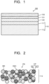
- FIG. 1 illustrates a cross section of a solid oxide cell according to an embodiment.
- the solid oxide cell illustrated in FIG. 1 is a hydrogen electrode-supported flat plate type electrochemical cell 100, and includes a stacked structure of a porous hydrogen electrode 110, a solid oxide electrolyte 120, and an oxygen electrode 130.
- the hydrogen electrode 110 includes a first hydrogen electrode layer 111 as a hydrogen electrode active layer arranged to be in contact with the solid oxide electrolyte 120, and a second hydrogen electrode layer 112 as a hydrogen electrode supporting layer in contact with a second surface opposite to a first surface of the first hydrogen electrode layer 111, the first surface being in contact with the solid oxide electrolyte 120.
- the solid oxide cell may include a reaction preventing layer 131 between the solid oxide electrolyte 120 and the oxygen electrode 130.
- the first hydrogen electrode layer 111 is composed of a porous layer made of a hydrogen electrode active material which causes a reaction by the hydrogen electrode 110, and concretely has gas permeability by the skeleton of a network structure.
- the first hydrogen electrode layer 111 has therein one or more of open pores that define at least one gas passages through which reactive gas (reducible gas) flows at least partially surrounded by the skeleton of the network structure, and can electrolyze water vapor flowing into the open pore into oxygen ions and hydrogen in the case of applying the electrochemical cell, for example, to a water vapor electrolysis cell.
- the first hydrogen electrode layer 111 includes a sintered compound (a sintered porous member) of a first metal particle and a first metal oxide particle.
- the first metal oxide particle preferably includes at least one selected from the group consisting of zirconia (ZrO 2 ) stabilized with at least one selected oxide from yttrium (Y) oxide and scandium(Sc) oxide, namely, at least one of yttrium oxide (Y 2 O 2 ) and scandium oxide (Sc 2 O 3 ), ceria (CeO 2 ) doped with at least one selected from samarium (Sm) oxide, gadolinium (Gd) oxide, and yttrium (Y) oxide, namely, at least one of samarium oxide (Sm 2 O 3 ), gadolinium oxide (Gd 2 O 3 ), and Y 2 O 3 , and strontium titanate (SrTiO 3 ) doped with yttrium (Y), which function as a part of the hydrogen electrode active
- the first metal particle contained in the aforementioned sintered member or solid-dissolved in the first metal oxide particle and functioning as the hydrogen electrode active material preferably contains at least one selected from the group consisting of nickel (Ni), copper (Cu), iron (Fe), and cobalt (Co).
- the first metal particle is not limited to a free particle of the aforementioned metal but may be an alloy particle containing the aforementioned metal.
- a ratio between the first metal particle and the first metal oxide particle is preferably 45:55 to 65:35 in mass ratio.
- the second hydrogen electrode layer 112 is a strength member which is mainly responsible for the strength of the electrochemical cell 100, is composed of a porous sintered member having gas permeability, and has a gas passage through which reactive gas (reducible gas) such as water vapor can flows.
- the second hydrogen electrode layer 112 includes a porous sintered member PS having a composite particle CP (M2/OX2) having a second metal oxide particle OX2 with a second metal particle M2 supported with the second metal oxide particle OX2 as illustrated in FIG. 2 .
- the porous sintered member PS constituting the second hydrogen electrode layer 112 may further have a third metal particle M3 and a third metal oxide particle OX3.
- the second metal particle M2 supported on the second metal oxide particle OX2 preferably contains at least one selected from the group consisting of Ni, Cu, Fe, and Co.
- the second metal particle M2 is not limited to the free particle of the aforementioned metal but may be an alloy particle containing the aforementioned metal.
- the second metal oxide particle OX2 preferably contains at least one selected from the group consisting of aluminium oxide such as alumina (Al 2 O 3 ), magnesium oxide such as magnesia (MgO), and silicon oxide such as silica (SiO 2 ).
- the second metal oxide particle OX2 may be a composite oxide particle containing two or more of the aforementioned metal oxides.
- the third metal particle M3 preferably contains at least one selected from the group consisting of Ni, Cu, Fe, and Co.
- the third metal particle M3 is not limited to the free particle of the aforementioned metal but may be an alloy particle containing the aforementioned metal.
- the third metal oxide particle OX3 preferably contains at least one selected from the group consisting of zirconia (ZrO 2 ) stabilized with oxide of at least one selected from Y and Sc, ceria (CeO 2 ) doped with oxide of at least one selected from Sm, Gd, and Y, and strontium titanate (SrTiOs) doped with Y
- the porous sintered member constituting the second hydrogen electrode layer 112 has the composite particle CP having the second metal oxide particle OX2 supporting the second metal particle M2.
- the second metal oxide particle OX2 contains at least one of alumina, magnesia, silica, and their composite oxides. These metal oxides are high in strength, and therefore the composite particle CP including the second metal oxide particle OX2 can reinforce or enhance the strength of the second hydrogen electrode layer 112 as the hydrogen electrode supporting layer. Accordingly, it possible to increase the strength of the second hydrogen electrode layer 112 and the electrochemical cell 100 having it. Further, the second metal oxide particle OX2 supports the second metal particle M2 and thus has electrical conduction. This can obtain the electrical conduction as the second hydrogen electrode layer 112 of the electrochemical cell 100.
- the third metal particle M3 and the third metal oxide particle OX3 also contribute to the electrical conduction of the second hydrogen electrode layer 112.
- the porous sintered member constituting the second hydrogen electrode layer 112 further has the third metal particle M3 and the third metal oxide particle OX3.
- the third metal particle M3 and the third metal oxide particle OX3 function as the hydrogen electrode active material which causes the reaction by the hydrogen electrode 110.
- the second hydrogen electrode layer 112 and the first hydrogen electrode layer 111 constitute the hydrogen electrode 110, and thereby can enhance the reactivity of the hydrogen electrode 110 being the main reaction of the electrochemical cell 100 and can dominantly promote the main reaction and decrease the occurrence percentage of undesirable side reactions.
- the volume ratio of the composite particles CP having the second metal oxide particles OX2 supporting the second metal particles M2 in the second hydrogen electrode layer 112 is preferably in a range of 3 vol% or more and 30 vol% or less. If the volume ratio of the composite particles CP is less than 3 vol%, the strength of the second hydrogen electrode layer 112 may not be sufficiently increased. If the volume ratio of the composite particles CP is more than 30 vol%, the reaction activity and the like of the second hydrogen electrode layer 112 may deteriorate.
- the volume ratio of the third metal particles M3 in the second hydrogen electrode layer 112 is preferably in a range of 30 vol% or more and 65 vol% or less. The volume ratio of the third metal oxide particles OX3 is preferably in a range of 30 vol% or more and 50 vol% or less.
- the second metal particles M2 preferably have an average particle size of 20 nm or more and 200 nm or less. If the average particle size of the second metal particles M2 is less than 20 nm, the electrical conduction may deteriorate. If the average particle size of the second metal particles M2 is more than 200 nm, the control of the reactivity by the hydrogen electrode 110 may deteriorate so that the percentage of side reaction may increase.
- the average particle size of the second metal particles M2 supported on the second metal oxide particles OX2 can be measured, for example, by observing the second metal oxide particles OX2 supporting the second metal particles M2 under the scanning electron microscope (SEM) and making it into a graphic representation (SEM image), and image-processing the SEM image.
- the solid oxide electrolyte 120 has one surface stacked on the hydrogen electrode 110 and another surface stacked on the oxygen electrode 130 via the reaction preventing layer 131.
- the solid oxide electrolyte 120 is made of a dense solid oxide electrolyte and is an ion conductor which allows ions such as an oxygen ion to pass therethrough but does not conduct electricity.
- the solid oxide electrolyte 120 is formed using stabilized zirconia in which at least one stabilizing agent selected from the group consisting of Y 2 O 3 , Sc 2 O 3 , Yb 2 O 3 , Gd 2 O 3 , CaO, MgO, and CeO 2 is solid-dissolved, a perovskite oxide expressed by Ln 1-x A x BO 3- ⁇ (Ln representing a rare earth element such as La, A representing at least one element selected from Sr, Ca, Ba, and so on, B representing at least one element selected from Ga, Cr, Mn, Co, Fe, Ni, and so on, x representing 0 ⁇ x ⁇ 1, ⁇ representing 0 ⁇ ⁇ ⁇ 1), or the like.
- at least one stabilizing agent selected from the group consisting of Y 2 O 3 , Sc 2 O 3 , Yb 2 O 3 , Gd 2 O 3 , CaO, MgO, and CeO 2 is solid-dissolved
- a perovskite oxide expressed by Ln
- the oxygen electrode 130 is made of an oxygen electrode active material and composed of a porous body having gas diffusibility and electronic conductivity, and can generate an oxygen molecule (O 2 ), for example, from an oxygen ion (O 2- ) reached the inside of the porous body from the solid oxide electrolyte 120 and an electron (e - ) supplied from an external power supply.
- the oxygen electrode 130 for example, a porous sintered member of a perovskite oxide expressed by Ln 1-x A x BO 3- ⁇ (Ln representing a rare earth element such as La, A representing at least one element selected from Sr, Ca, Ba, and so on, B representing at least one element selected from Ga, Cr, Mn, Co, Fe, Ni, and so on, x representing 0 ⁇ x ⁇ 1, ⁇ representing 0 ⁇ ⁇ ⁇ 1) is used.
- Representative examples of the constituent material of the oxygen electrode 130 include (La 1-x Sr x )(Co 1-y Fe y )O 3- ⁇ (LSCF).
- the reaction preventing layer 131 is a dense reaction preventing layer which is arranged when necessary between the solid oxide electrolyte 120 and the oxygen electrode 130 and prevents the diffusion and the reaction of elements between the solid oxide electrolyte 120 and the oxygen electrode 130.
- the electrochemical cell 100 in the embodiment is constituted by stacking in order the second hydrogen electrode layer 112, the first hydrogen electrode layer 111, the solid oxide electrolyte 120, the reaction preventing layer 131, and the oxygen electrode 130.
- the electrochemical cell 100 is made, for example, by forming a precursor layer of the second hydrogen electrode layer 112, a precursor layer of the first hydrogen electrode layer 111, and the solid oxide electrolyte 120 in order and heating them.
- the reaction preventing layer 131 and the oxygen electrode 130 are formed in order on the heated stack and heated.
- the sintered member is heated in a reducing atmosphere.
- metal oxide particles are used as forming materials of the first metal particle, the second metal particle, and the third metal particle, and they are heated in the reducing atmosphere to form metal particles, thereby producing the electrochemical cell 100.
- the electrochemical cell 100 in the embodiment may be used as it is, or may be used as an electrochemical cell stack including a plurality of electrochemical cells 100 in a stacked state.
- the electrochemical cell 100 in the embodiment is used for a CO 2 electrolysis device, a CO 2 /H 2 O co-electrolysis device, a water vapor electrolysis device, a fuel cell device, and the like.
- the electrochemical cell 100 in the embodiment is preferable for the CO 2 electrolysis device and the CO 2 /H 2 O co-electrolysis device among them.
- NiO powder and Al 2 O 3 powder were mixed and heated to produce a nickel aluminum composite oxide expressed by NiAl 2 O 4 .
- Powder which was made by mixing powder obtained by mixing NiO and ceria (GDC10) doped with Gd 2 O 3 at a mass ratio of 6:4 into a composition of (Gd 2 O 3 ) 0.1 (CeO 2 ) 0.9 and the composite oxide particles, was made into a paste, and this paste was made into a sheet to produce the second hydrogen electrode layer (hydrogen electrode base) precursor.
- the paste containing a mixture of NiO and GDC10 as the first hydrogen electrode layer (hydrogen electrode active layer) precursor and a paste containing zirconia (YSZ8) doped with Y 2 O 3 to have a composition of (Y 2 O 3 ) 0.08 (ZrO 2 ) 0.92 as the electrolyte were formed in order on the second hydrogen electrode layer precursor.
- the second hydrogen electrode layer precursor-first hydrogen electrode layer precursor-electrolyte was heated under the condition of 1200°C or higher and 1500°C or lower until sufficient strength was achieved in each layer and between layers.
- the paste of GDC10 was formed into a sheet as the reaction preventing layer on the heated stack, and heated under the condition of 1200°C or higher and 1500°C or lower until sufficient strength was achieved in each layer and between layers. Subsequently, the paste of La(Sr)Co(Fe)O 3- ⁇ (LSCF) was formed into a sheet as the oxygen electrode on the reaction preventing layer, and heated under the condition of 900°C or higher and 1200°C or lower to produce a precursor of the solid oxide cell in Example 1.
- LSCF La(Sr)Co(Fe)O 3- ⁇
- Example 1 The above precursor of the solid oxide cell in Example 1 was set in an output characteristic evaluation device, and dry hydrogen was made to flow to the hydrogen electrode side at 700°C or higher and N 2 /O 2 mixed gas mixed at a volume ratio of 4:1 was made to flow to the oxygen electrode side to reduce the first hydrogen electrode layer precursor and the second hydrogen electrode layer precursor, thereby forming the first hydrogen electrode layer and the second hydrogen electrode layer.
- the hydrogen electrode output characteristic evaluation device can supply mixed gas of water vapor, CO 2 , and H 2 O mixed at an arbitrary ratio to the hydrogen electrode side, operate the solid oxide cell in an SOFC mode, an SOEC mode, and a co-electrolysis mode, and evaluate I-V characteristics at that time. After the reduction reaction was performed, the hydrogen electrode output characteristic evaluation device operated the solid oxide cell at a measurement temperature as the SOFC, the SOEC, and the co-electrolysis device, and evaluated I-V characteristics at the initial stage.
- NiO powder and MgO powder were mixed and heated to produce a nickel magnesium composite oxide expressed by NiMgO. This was pulverized into composite oxide particles.
- Powder which was made by mixing powder obtained by mixing NiO and ceria (GDC10) doped with Gd 2 O 3 at a mass ratio of 6:4 and the composite oxide particles, was made into a paste, and this paste was made into a sheet to produce the second hydrogen electrode layer (hydrogen electrode base) precursor. Thereafter, the paste containing a mixture of NiO and GDC10 as the first hydrogen electrode layer (hydrogen electrode active layer) precursor and a paste containing Y-stabilized zirconia (YSZ8) as the electrolyte were formed in order on the second hydrogen electrode layer precursor. Thereafter, the second hydrogen electrode layer precursor-first hydrogen electrode layer precursor-electrolyte was heated under the condition of 1200°C or higher and 1500°C or lower until sufficient strength was achieved in each layer and between layers.
- the paste of GDC10 was formed into a sheet as the reaction preventing layer on the heated stack, and heated under the condition of 1000°C or higher and 1500°C or lower until sufficient strength was achieved in each layer and between layers. Subsequently, the paste of La(Sr)Co(Fe)O 3- ⁇ (LSCF) was formed into a sheet as the oxygen electrode on the reaction preventing layer, and heated under the condition of 900°C or higher and 1200°C or lower to produce a precursor of the solid oxide cell in Example 2.
- LSCF La(Sr)Co(Fe)O 3- ⁇
- the above precursor of the solid oxide cell in Example 2 was set in the output characteristic evaluation device, and dry hydrogen was made to flow to the hydrogen electrode side at 700°C or higher and N 2 /O 2 mixed gas mixed at a volume ratio of 4:1 was made to flow to the oxygen electrode side to reduce the first hydrogen electrode layer precursor and the second hydrogen electrode layer precursor, thereby forming the first hydrogen electrode layer and the second hydrogen electrode layer.
- the hydrogen electrode output characteristic evaluation device evaluated I-V characteristics in the initial state as in Example 1.
- NiO powder, MgO powder, and SiO 2 powder were mixed and heated to produce a nickel magnesium silica composite oxide expressed by NiMgO-SiO 2 . This was pulverized into composite oxide particles. Powder, which was made by mixing powder obtained by mixing NiO and ceria (GDC10) doped with Gd 2 O 3 at a mass ratio of 6:4 and the composite oxide particles, was made into a paste, and this paste was made into a sheet to produce the second hydrogen electrode layer (hydrogen electrode base) precursor.
- GDC10 NiO and ceria
- the paste containing a mixture of NiO and GDC10 as the first hydrogen electrode layer (hydrogen electrode active layer) precursor and a paste containing Y-stabilized zirconia (YSZ8) as the electrolyte were formed in order on the second hydrogen electrode layer precursor.
- the second hydrogen electrode layer precursor-first hydrogen electrode layer precursor-electrolyte was heated under the condition of 1200°C or higher and 1500°C or lower until sufficient strength was achieved in each layer and between layers.
- the paste of GDC10 was formed into a sheet as the reaction preventing layer on the heated stack, and heated under the condition of 1000°C or higher and 1500°C or lower until sufficient strength was achieved in each layer and between layers. Subsequently, the paste of La(Sr)Co(Fe)O 3- ⁇ (LSCF) was formed into a sheet as the oxygen electrode on the reaction preventing layer, and heated under the condition of 900°C or higher and 1200°C or lower to produce a precursor of the solid oxide cell in Example 3.
- LSCF La(Sr)Co(Fe)O 3- ⁇
- the above precursor of the solid oxide cell in Example 3 was set in the output characteristic evaluation device, and dry hydrogen was made to flow to the hydrogen electrode side at 700°C or higher and N 2 /O 2 mixed gas mixed at a volume ratio of 4:1 was made to flow to the oxygen electrode side to reduce the first hydrogen electrode layer precursor and the second hydrogen electrode layer precursor, thereby forming the first hydrogen electrode layer and the second hydrogen electrode layer.
- the hydrogen electrode output characteristic evaluation device evaluated I-V characteristics in the initial state as in Example 1.
- the paste of GDC10 was formed into a sheet as the reaction preventing layer on the heated stack, and heated under the condition of 1000°C or higher and 1500°C or lower until sufficient strength was achieved in each layer and between layers. Subsequently, the paste of La(Sr)Co(Fe)O 3- ⁇ (LSCF) was formed into a sheet as the oxygen electrode on the reaction preventing layer, and heated under the condition of 900°C or higher and 1200°C or lower to produce a precursor of the solid oxide cell in Example 4.
- LSCF La(Sr)Co(Fe)O 3- ⁇
- the above precursor of the solid oxide cell in Example 4 was set in the output characteristic evaluation device, and dry hydrogen was made to flow to the hydrogen electrode side at 700°C or higher and N 2 /O 2 mixed gas mixed at a volume ratio of 4:1 was made to flow to the oxygen electrode side to reduce the first hydrogen electrode layer precursor and the second hydrogen electrode layer precursor, thereby forming the first hydrogen electrode layer and the second hydrogen electrode layer.
- the hydrogen electrode output characteristic evaluation device evaluated I-V characteristics in the initial state as in Example 1.
- CuO powder, MgO powder, and SiO 2 powder were mixed and heated to produce a copper magnesium composite oxide expressed by CuMgO. This was pulverized into composite oxide particles.
- Powder which was made by mixing powder obtained by mixing NiO and ceria (GDC10) doped with Gd 2 O 3 at a mass ratio of 6:4 and the composite oxide particles, was made into a paste, and this paste was made into a sheet to produce the second hydrogen electrode layer (hydrogen electrode base) precursor. Thereafter, the paste containing a mixture of NiO and GDC10 as the first hydrogen electrode layer (hydrogen electrode active layer) precursor and a paste containing Y-stabilized zirconia (YSZ8) as the electrolyte were formed in order on the second hydrogen electrode layer precursor. Thereafter, the second hydrogen electrode layer precursor-first hydrogen electrode layer precursor-electrolyte was heated under the condition of 1200°C or higher and 1500°C or lower until sufficient strength was achieved in each layer and between layers.
- the paste of GDC10 was formed into a sheet as the reaction preventing layer on the heated stack, and heated under the condition of 1000°C or higher and 1500°C or lower until sufficient strength was achieved in each layer and between layers. Subsequently, the paste of La(Sr)Co(Fe)O 3- ⁇ (LSCF) was formed into a sheet as the oxygen electrode on the reaction preventing layer, and heated under the condition of 900°C or higher and 1200°C or lower to produce a precursor of the solid oxide cell in Example 5.
- LSCF La(Sr)Co(Fe)O 3- ⁇
- the above precursor of the solid oxide cell in Example 5 was set in the output characteristic evaluation device, and dry hydrogen was made to flow to the hydrogen electrode side at 700°C or higher and N 2 /O 2 mixed gas mixed at a volume ratio of 4:1 was made to flow to the oxygen electrode side to reduce the first hydrogen electrode layer precursor and the second hydrogen electrode layer precursor, thereby forming the first hydrogen electrode layer and the second hydrogen electrode layer.
- the hydrogen electrode output characteristic evaluation device evaluated I-V characteristics in the initial state as in Example 1.
- CuO powder and Al 2 O 3 powder were mixed and heated to produce a copper aluminum composite oxide expressed by CuAl 2 O 4 .
- Powder which was made by mixing powder obtained by mixing NiO and zirconia (YSZ8) doped with Y 2 O 3 at a mass ratio of 6:4 to have a composition of (Y 2 O 3 ) 0.08 (ZrO 2 ) 0.92 and the composite oxide particles, was made into a paste, and this paste was made into a sheet to produce the second hydrogen electrode layer (hydrogen electrode base) precursor.
- the paste containing NiO and YSZ8 as the first hydrogen electrode layer (hydrogen electrode active layer) precursor and a paste containing Y-stabilized zirconia (YSZ8) as the electrolyte were formed in order on the second hydrogen electrode layer precursor.
- the second hydrogen electrode layer precursor-first hydrogen electrode layer precursor-electrolyte was heated under the condition of 1200°C or higher and 1500°C or lower until sufficient strength was achieved in each layer and between layers.
- the paste of GDC10 was formed into a sheet as the reaction preventing layer on the heated stack, and heated under the condition of 1000°C or higher and 1500°C or lower until sufficient strength was achieved in each layer and between layers. Subsequently, the paste of La(Sr)Co(Fe)O 3- ⁇ (LSCF) was formed into a sheet as the oxygen electrode on the reaction preventing layer, and heated under the condition of 900°C or higher and 1200°C or lower to produce a precursor of the solid oxide cell in Example 6.
- LSCF La(Sr)Co(Fe)O 3- ⁇
- the above precursor of the solid oxide cell in Example 6 was set in the output characteristic evaluation device, and dry hydrogen was made to flow to the hydrogen electrode side at 700°C or higher and N 2 /O 2 mixed gas mixed at a volume ratio of 4:1 was made to flow to the oxygen electrode side to reduce the first hydrogen electrode layer precursor and the second hydrogen electrode layer precursor, thereby forming the first hydrogen electrode layer and the second hydrogen electrode layer.
- the hydrogen electrode output characteristic evaluation device evaluated I-V characteristics in the initial state as in Example 1.
- CuO powder and Al 2 O 3 powder were mixed and heated to produce a copper aluminum composite oxide expressed by CuAl 2 O 4 .
- Powder which was made by mixing powder obtained by mixing NiO and strontium titanate (YST) doped with Y at a mass ratio of 6:4 to have a composition of Sr(Y)TiO 3 and the composite oxide particles, was made into a paste, and this paste was made into a sheet to produce the second hydrogen electrode layer (hydrogen electrode base) precursor.
- YST NiO and strontium titanate
- the paste containing a mixture of NiO and YSZ8 as the first hydrogen electrode layer (hydrogen electrode active layer) precursor and a paste containing Y-stabilized zirconia (YSZ8) as the electrolyte were formed in order on the second hydrogen electrode layer precursor.
- the second hydrogen electrode layer precursor-first hydrogen electrode layer precursor-electrolyte was heated under the condition of 1200°C or higher and 1500°C or lower until sufficient strength was achieved in each layer and between layers.
- the paste of GDC10 was formed into a sheet as the reaction preventing layer on the heated stack, and heated under the condition of 1000°C or higher and 1500°C or lower until sufficient strength was achieved in each layer and between layers. Subsequently, the paste of La(Sr)Co(Fe)O 3- ⁇ (LSCF) was formed into a sheet as the oxygen electrode on the reaction preventing layer, and heated under the condition of 900°C or higher and 1200°C or lower to produce a precursor of the solid oxide cell in Example 7.
- LSCF La(Sr)Co(Fe)O 3- ⁇
- the above precursor of the solid oxide cell in Example 7 was set in the output characteristic evaluation device, and dry hydrogen was made to flow to the hydrogen electrode side at 700°C or higher and N 2 /O 2 mixed gas mixed at a volume ratio of 4:1 was made to flow to the oxygen electrode side to reduce the first hydrogen electrode layer precursor and the second hydrogen electrode layer precursor, thereby forming the first hydrogen electrode layer and the second hydrogen electrode layer.
- the hydrogen electrode output characteristic evaluation device evaluated I-V characteristics in the initial state as in Example 1.
- a paste of powder obtained by mixing NiO and ceria (GDC10) doped with Gd 2 O 3 at a mass ratio of 6:4 was made into a sheet to produce the second hydrogen electrode layer (hydrogen electrode base) precursor.
- the paste containing a mixture of NiO and GDC10 as the first hydrogen electrode layer (hydrogen electrode active layer) precursor and a paste containing Y-stabilized zirconia (YSZ8) as the electrolyte were formed in order on the second hydrogen electrode layer precursor.
- the second hydrogen electrode layer precursor-first hydrogen electrode layer precursor-electrolyte was heated under the condition of 1200°C or higher and 1500°C or lower until sufficient strength was achieved in each layer and between layers.
- the paste of GDC10 was formed into a sheet as the reaction preventing layer on the heated stack, and heated under the condition of 1000°C or higher and 1500°C or lower until sufficient strength was achieved in each layer and between layers. Subsequently, the paste of La(Sr)Co(Fe)O 3- ⁇ (LSCF) was formed into a sheet as the oxygen electrode on the reaction preventing layer, and heated under the condition of 900°C or higher and 1200°C or lower to produce a precursor of the solid oxide cell in Comparative example 1.
- LSCF La(Sr)Co(Fe)O 3- ⁇
- the above precursor of the solid oxide cell in Comparative example 1 was set in the output characteristic evaluation device, and dry hydrogen was made to flow to the hydrogen electrode side at 700°C or higher and N 2 /O 2 mixed gas mixed at a volume ratio of 4:1 was made to flow to the oxygen electrode side to reduce the first hydrogen electrode layer precursor and the second hydrogen electrode layer precursor, thereby forming the first hydrogen electrode layer and the second hydrogen electrode layer.
- the hydrogen electrode output characteristic evaluation device evaluated I-V characteristics in the initial state as in Example 1.
- Composite oxide particles supporting Ni metal particles on the surface of Al 2 O 3 powder was prepared using a nickel nitrate solution. Powder, which was made by mixing powder obtained by mixing nickel oxide (NiO) and ceria (GDC10) doped with Gd 2 O 3 at a mass ratio of 6:4 and the composite oxide particles, was made into a paste, and this paste was made into a sheet to produce the second hydrogen electrode layer (hydrogen electrode base) precursor.
- the paste containing a mixture of NiO and GDC10 as the first hydrogen electrode layer (hydrogen electrode active layer) precursor and a paste containing Y-stabilized zirconia (YSZ8) as the electrolyte were formed in order on the second hydrogen electrode layer precursor. Thereafter, the second hydrogen electrode layer precursor-first hydrogen electrode layer precursor-electrolyte was heated under the condition of 1200°C or higher and 1500°C or lower until sufficient strength was achieved in each layer and between layers.
- the paste of GDC10 was formed into a sheet as the reaction preventing layer on the heated stack, and heated under the condition of 1000°C or higher and 1500°C or lower until sufficient strength was achieved in each layer and between layers. Subsequently, the paste of La(Sr)Co(Fe)O 3- ⁇ (LSCF) was formed into a sheet as the oxygen electrode on the reaction preventing layer, and heated under the condition of 900°C or higher and 1200°C or lower to produce a precursor of the solid oxide cell in Reference example 1.
- LSCF La(Sr)Co(Fe)O 3- ⁇
- the above precursor of the solid oxide cell in Reference example 1 was set in the output characteristic evaluation device, and dry hydrogen was made to flow to the hydrogen electrode side at 700°C or higher and N 2 /O 2 mixed gas mixed at a volume ratio of 4:1 was made to flow to the oxygen electrode side to reduce the first hydrogen electrode layer precursor and the second hydrogen electrode layer precursor, thereby forming the first hydrogen electrode layer and the second hydrogen electrode layer.
- the hydrogen electrode output characteristic evaluation device evaluated I-V characteristics in the initial state as in Example 1.
- the main reaction percentages were calculated from the reaction amounts of outlet gas in a co-electrolysis mode in Examples 1 to 7, Comparative example 1, and Reference example 1. The results are listed in Table 1. Table 1 lists the second metal particle, the second metal oxide particle, the third metal oxide particle, and the average particle size of the second metal particles as well.
- the main reaction percentages of the cells in Examples 1 to 3 are almost the same and higher than the percentage in Comparative example 1, showing the effect of the Ni metal particles.
- the average particle size of the second metal particles in Reference example 1 produced by the impregnation method is 300 nm which is larger than that in Example 1, showing that effect of preventing of reducing the side reaction is low.
- Example 4 Example 1, and Reference example 1, the main reaction percentage can be made higher in Example 4, showing that the effect of preventing or reducing the side reaction is higher by Cu than by Ni. Further, the main reaction percentages in Examples 4 to 7 are almost the same, showing that any of the metal particles selected here can exert the effect of Cu.
Landscapes
- Chemical & Material Sciences (AREA)
- Chemical Kinetics & Catalysis (AREA)
- Electrochemistry (AREA)
- Engineering & Computer Science (AREA)
- Materials Engineering (AREA)
- Metallurgy (AREA)
- Organic Chemistry (AREA)
- General Chemical & Material Sciences (AREA)
- Composite Materials (AREA)
- Inorganic Chemistry (AREA)
- Ceramic Engineering (AREA)
- Fuel Cell (AREA)
- Inert Electrodes (AREA)
- Electrodes For Compound Or Non-Metal Manufacture (AREA)
- Electrolytic Production Of Non-Metals, Compounds, Apparatuses Therefor (AREA)
Applications Claiming Priority (1)
| Application Number | Priority Date | Filing Date | Title |
|---|---|---|---|
| JP2023119239A JP2025016150A (ja) | 2023-07-21 | 2023-07-21 | 固体酸化物形電気化学セル及び固体酸化物形電気化学セルスタック |
Publications (2)
| Publication Number | Publication Date |
|---|---|
| EP4496045A2 true EP4496045A2 (de) | 2025-01-22 |
| EP4496045A3 EP4496045A3 (de) | 2025-03-26 |
Family
ID=91950223
Family Applications (1)
| Application Number | Title | Priority Date | Filing Date |
|---|---|---|---|
| EP24188580.5A Pending EP4496045A3 (de) | 2023-07-21 | 2024-07-15 | Festoxidbrennstoffzelle und festoxidbrennstoffzellenstapel |
Country Status (3)
| Country | Link |
|---|---|
| US (1) | US20250027217A1 (de) |
| EP (1) | EP4496045A3 (de) |
| JP (1) | JP2025016150A (de) |
Family Cites Families (3)
| Publication number | Priority date | Publication date | Assignee | Title |
|---|---|---|---|---|
| JP5244423B2 (ja) * | 2008-02-29 | 2013-07-24 | 株式会社東芝 | 固体酸化物型電気化学セル、およびその製造方法 |
| JP2012033418A (ja) * | 2010-07-30 | 2012-02-16 | Toshiba Corp | 固体酸化物型燃料電池、及びその製造方法 |
| JP6518256B2 (ja) * | 2014-01-09 | 2019-05-22 | 潮州三環(集団)股▲ふん▼有限公司Chaozhou Three−Circle (Group) Co.,Ltd. | 電気化学エネルギー変換装置及び電池、並びにそれらの正極側材料 |
-
2023
- 2023-07-21 JP JP2023119239A patent/JP2025016150A/ja active Pending
-
2024
- 2024-07-12 US US18/770,838 patent/US20250027217A1/en active Pending
- 2024-07-15 EP EP24188580.5A patent/EP4496045A3/de active Pending
Also Published As
| Publication number | Publication date |
|---|---|
| JP2025016150A (ja) | 2025-01-31 |
| US20250027217A1 (en) | 2025-01-23 |
| EP4496045A3 (de) | 2025-03-26 |
Similar Documents
| Publication | Publication Date | Title |
|---|---|---|
| EP3719815A1 (de) | Protonenleiter, protonenleitende zellstruktur, wasserdampfelektrolysezelle und verfahren zur herstellung eines wasserstoff-elektroden-festelektrolyt-schichtkomplexes | |
| JP2021155852A (ja) | 高温水蒸気電解セルの製造方法、高温水蒸気電解セル用水素極層の製造方法及び固体酸化物電気化学セルの製造方法 | |
| US20250046825A1 (en) | Electrode and Electrochemical Cell | |
| US20230395813A1 (en) | Fuel electrode and electrochemical cell | |
| EP2936597B1 (de) | Pulvergemisch für schicht in einer festoxidbrennstoffzelle | |
| US11682771B2 (en) | Electrochemical cell and electrochemical cell stack | |
| CN117999679A (zh) | 电极和电化学电池 | |
| JP2023147070A (ja) | サーメット層、及び、水蒸気電解用水素極 | |
| CA2675988A1 (en) | A composite material suitable for use as an electrode material in a soc | |
| JP2022181976A (ja) | 水蒸気電解用水素極 | |
| EP4496045A2 (de) | Festoxidbrennstoffzelle und festoxidbrennstoffzellenstapel | |
| US12244044B2 (en) | Direct ammonia-fed solid oxide fuel cell and methods for making the same | |
| EP4588114A2 (de) | Elektrode und elektrochemische zelle | |
| JP7719638B2 (ja) | 固体酸化物形電気化学セル及びその利用 | |
| JP7301768B2 (ja) | 電気化学セル、電気化学セルスタックおよび電気化学セル用電解質 | |
| EP4481863A1 (de) | Elektrode und elektrochemische zelle | |
| US20220029195A1 (en) | Electrochemical cell | |
| WO2023203870A1 (ja) | 電気化学セル | |
| WO2023203875A1 (ja) | 電気化学セル | |
| WO2023195245A1 (ja) | 電気化学セル | |
| WO2024184651A1 (en) | Electrode and electrochemical cell | |
| HK40092151A (en) | Electrode and electrochemical cell |
Legal Events
| Date | Code | Title | Description |
|---|---|---|---|
| PUAI | Public reference made under article 153(3) epc to a published international application that has entered the european phase |
Free format text: ORIGINAL CODE: 0009012 |
|
| STAA | Information on the status of an ep patent application or granted ep patent |
Free format text: STATUS: REQUEST FOR EXAMINATION WAS MADE |
|
| 17P | Request for examination filed |
Effective date: 20240715 |
|
| AK | Designated contracting states |
Kind code of ref document: A2 Designated state(s): AL AT BE BG CH CY CZ DE DK EE ES FI FR GB GR HR HU IE IS IT LI LT LU LV MC ME MK MT NL NO PL PT RO RS SE SI SK SM TR |
|
| PUAL | Search report despatched |
Free format text: ORIGINAL CODE: 0009013 |
|
| AK | Designated contracting states |
Kind code of ref document: A3 Designated state(s): AL AT BE BG CH CY CZ DE DK EE ES FI FR GB GR HR HU IE IS IT LI LT LU LV MC ME MK MT NL NO PL PT RO RS SE SI SK SM TR |
|
| RIC1 | Information provided on ipc code assigned before grant |
Ipc: H01M 8/12 20160101ALN20250214BHEP Ipc: H01M 4/90 20060101ALI20250214BHEP Ipc: H01M 4/86 20060101AFI20250214BHEP |